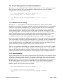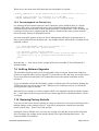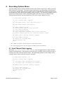
1
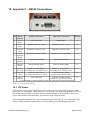
18. Appendix C – RS232 Connections
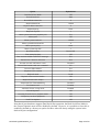
Pin
RS232
Function
AntiLog connections
AntiLogPro connections
Direction
1
Carrier
Detect
[Not connected]
Digital Input
in
2
Receive
Data
Main Port, Receive (Rx1)
Main Port, Receive (Rx1)
in
3
Transmit
Data
Main Port, Transmit (Tx1)
Main Port, Transmit (Tx1)
out
Data Terminal Ready (DTR)
Data Terminal Ready (DTR)
out
4
Data
Terminal
Ready
5
Signal
Ground
Signal Ground (GND)
Signal Ground (GND)
-
6
Data Set
Ready
Data Set Ready (DSR)
Data Set Ready (DSR)
in
7
Request
To Send
Request To Send (RTS) or
Secondary Port, Transmit[1] (Tx2)
Request To Send (RTS) or
Secondary Port, Transmit (Tx2)
out
8
Clear To
Send
Clear To Send (CTS) or
Secondary Port, Receive[1] (Rx2)
Clear To Send (CTS) or
Secondary Port, Receive (Rx2)
in
9
Ring
Indicator
[Not connected]
Linked to EventIn (boxed),
Routed to J3 pin 18 only (OEM)
in
[1] Only available on AntiLog hardware revision C or higher with Dual Serial Port Enabled.
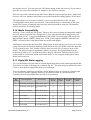
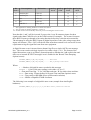
Table 1: 9-way D Connector Wiring
18.1 DC Power
External DC power can be supplied via a 6.5/2.1mm power jack for AntiLog and a 1.3mm
power jack for AntiLogPro. Note that the power jack does not disable the internal PP3 cell so
the voltage supplied must exceed the battery terminal voltage of the fitted PP3, otherwise
power will be taken from the battery in preference to the external source.
Power supplied through the DC socket cannot charge the internal cell. If a rechargeable PP3
battery is used then this must be taken out of the AntiLog case and charged separately.
DOC/AntiLog/UG/2003001_5.1
Page 85 of 90