1
_________________________________________________________________Package contents
3.6 Metering module
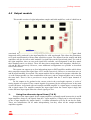
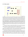
This is our simplest module, providing the facility to read the actual signal levels on the
different signal lines of the internal back plane. These are grouped into two sets of eight, referred to
as set A and set B. The front panel has a rotary dial to switch between the different signal lines,
with an additional two-way toggle switch to select the set to be read. In a normal system with one
input module, most signals will be present on the A signal lines, so the toggle switch should be in
the "A" (left) position to read these signals. However, when one or more gain/offset modules are
used, the outputs from the individual stages in the module(s) will normally be available on the
corresponding B signal lines, although other arrangements are also possible as described in the
gain/offset module documentation. The signal line to be measured on the selected set is determined
by the rotary dial position. Positions one to eight are the basic signal lines output from preceding
modules; the next position, labelled "inputs", carries the outputs from the primary amplifier
modules (The input or PMT amplifiers). Adjacent to position one, labelled "amp", is a signal line
used to carry the outputs from one or two ratio amplifier modules, thus allowing them to be
displayed on the meter.
The basic sensitivity of the meter is 1.999V full scale in either polarity, but for signals with
an absolute value of more than about 1.8V an auto-ranging facility is activated, giving a tenfold
reduction in the sensitivity to 19.99V full scale in either polarity. The meter decimal point is shifted
so that the voltage as displayed remains correct. The maximum voltage on any signal line is always
within this range, so the meter reading will always be correct. However, if the measured voltage is
more than about 12V in either polarity, then the module that has produced the measured voltage is
probably in saturation. In general, signal levels should be kept below 10 volts, and ideally in the 1-5
volt range.
Typically the meter will be used in conjunction with an output module and a gain/offset
module, allowing a set of signals to be measured and displayed both before and after offset
correction. This enables the amount of offset on any signal to be easily ascertained at any time
without disturbing the signal. In this example the system would contain a gain/offset module
configured so the signals before application of the offset are available on set A and after on set B.
_________________________________________________________________________Page