1
The relay has 2 amp contacts; the operation of the SP-1 is fail safe. When the SP-1 receives
power, its control relay automatically energizes. It de-energizes when the plate is touched. For
applications releasing an electric lock, the following drawing (Figure 2) shows typical connections
of sensor, power supply and both fail safe (secure when powered) or fail secure (released
when powered) electric locks. Note installation of the MOV in parallel with the electric lock. The
MOV is supplied loose with the SP-1. It is a black or blue disk-like component with two bare
wires for connection. The MOV acts to suppress the inductive kickback from the lock which will
greatly shorten the life of the relay contacts if not suppressed. To work properly it should be
spliced in as close to the electric lock as possible.
It has no polarity.
If, however,
Securitron's Magnalock is used in the installation, the MOV is not necessary as the
Magnalock is internally suppressed.
The sensor operates on 12-24 volts DC and is normally powered by the same power supply that
operates the electric lock. When wiring power, polarity must be observed. Note that the
sensor draws 40 mA when "at rest" and 25 mA when it is releasing the lock. . As an additional
safety feature, the SP-1 includes a low voltage sensing circuit. The unit will keep working
normally if input voltage declines until it reaches roughly 9 volts. At that point, the SP-1 will
automatically act as if all power was removed. If a lock is being controlled, it will release. Input
voltage could decline if the unit was being operated on batteries and the batteries were
discharging or because of a fault in the power supply.
When employing the cable to make electrical connections, never coil the gray cable within
the white backbox. It must be pulled straight out. A coiled cable in the white backbox will
interfere with proper electronic operation of the unit.
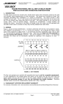
FIGURE 2: SP-1 TYPICAL WIRING
WIRING FOR FAIL SAFE LOCK
CABLE
RED (+ POWER)
BLACK (- POWER)
WHITE (RELAY COM1)
GREEN (RELAY N.C.1)
+
MOV
POWER SUPPLY
12-24 VDC
ELECTRIC
LOCK
WIRING FOR FAIL SECURE LOCK
CABLE
RED (+ POWER)
BLACK (- POWER)
BLUE (RELAY COM2)
ORANGE (RELAY N.O.2)
+
-
MOV
POWER SUPPLY
12-24 VDC
ELECTRIC
LOCK
NOTE 1: MOV NOT NEEDED IF SECURITRON MAGNALOCK USED
NOTE 2: POWER SUPPLY MUST ALWAYS CONNECT DIRECTLY TO
SENSOR. OTHER CONTROL SWITCHES SHOULD BREAK OR PARALLEL RELAY CONTACTS.
NOTE 3: INPUT POWER POLARITY MUST BE OBSERVED.
3.1 DOUBLE BREAK WIRING
Many installations include a controlled entry device such as a digital keypad or card reader.
Such devices typically have a REX (request to exit) input.
If the REX input alone is used for exiting a safety/reliability problem will exist. If the entry
device malfunctions, exit will not be possible and people may be trapped. We therefore always
recommend double break wiring which is supported by the SP-1 because of its two pole relay.
The SP-1's NC contacts are used to break power to the fail safe electric lock while its NO
contacts trip the REX input of the controlled entry device. This releases the lock a second time,
hence the term, "double break". If the controlled entry device fails for any reason, direct exit is
still possible. This type of circuit works only with fail safe locks but these comprise the great
majority of lock types used for safety related exit.
Page 2
PN# 500-15600
Rev. D, 03/11