1
BHFQ22P1007
BHFQ22P1517
Installation manual
Outdoor unit multi connection piping kit
IMPROPER INSTALLATION OR ATTACHMENT OF EQUIPMENT OR ACCESSORIES COULD RESULT IN ELECTRIC SHOCK, SHORTCIRCUIT, LEAKS, FIRE OR OTHER DAMAGE TO THE EQUIPMENT. BE SURE ONLY TO USE ACCESSORIES MADE BY DAIKIN WHICH
ARE SPECIFICALLY DESIGNED FOR USE WITH THE EQUIPMENT AND HAVE THEM INSTALLED BY A PROFESSIONAL.
IF UNSURE OF INSTALLATION PROCEDURES OR USE, ALWAYS CONTACT YOUR DAIKIN DEALER FOR ADVICE AND
INFORMATION.
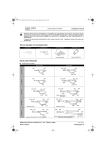
This kit includes the following parts
Table 1
Shape
Kit
name
Gas side joint
Liquid side joint
Reducer for gas pipe
(1)
ID Ø31.8
ID Ø28.6
(3)
(2)
(7)
(9)
(1)
(3)
(5)
ID Ø22.2
ID Ø19.1
ID Ø15.9
BHFQ22P1007
Insulation
Gas Liquid
Reducer for liquid pipe
ID Ø19.1
ID Ø22.2
ID Ø25.4
ID Ø38.1
ID Ø28.6
OD Ø31.8
ID Ø19.1
ID Ø22.2
ID Ø25.4
ID Ø9.5
ID Ø28.6
OD Ø31.8
OD Ø25.4
ID Ø28.6
ID Ø25.4
ID Ø22.2
ID Ø19.1
ID Ø15.9
ID Ø12.7
OD Ø12.7
OD Ø25.4
ID Ø25.4
ID Ø9.5
ID Ø12.7
ID Ø41.3
ID Ø34.9
OD Ø15.9
OD Ø31.8
OD Ø15.9
ID Ø15.9
ID Ø12.7
ID Ø9.5
1x
1x
(1)
1x
(1)
(1)
ID Ø38.1
ID Ø31.8
ID Ø22.2
ID Ø19.1
1x
1x
(3)
(2)
1x
1x
(4)
(5)
ID Ø19.1
ID Ø22.2
ID Ø25.4
ID Ø38.1
ID Ø19.1
ID Ø22.2
ID Ø25.4
ID Ø28.6
ID Ø31.8
ID Ø28.6
OD Ø31.8
ID Ø28.6
OD Ø31.8
1x
(1)
1x
(2)
ID Ø31.8
1x
1x
1x
2x
2x
(3)
ID Ø19.1
ID Ø9.5
ID Ø15.9
ID Ø12.7
OD Ø28.6
OD Ø25.4
OD Ø25.4
OD Ø15.9
OD Ø12.7
ID Ø15.9
BHFQ22P1517
ID Ø25.4
ID Ø15.9
ID Ø19.1
ID Ø28.6
ID Ø31.8
1x
ID Ø9.5
ID Ø12.7
1x
(2)
(2)
2x
(6)
1x
(7)
1x
(8)
1x
1x
(9)
(10)
OD Ø15.9
1x
(4)
2x
(5)
ID Ø31.8
ID Ø28.6
ID Ø19.1
ID Ø15.9
ID Ø15.9
ID Ø22.2
ID Ø25.4
ID Ø34.9
ID Ø41.3
OD Ø31.8
OD Ø38.1
ID Ø41.3
ID Ø15.9
OD Ø28.6
OD Ø12.7
OD Ø31.8
ID Ø19.1
ID Ø25.4
OD Ø19.1
ID Ø15.9
ID Ø28.6
ID Ø25.4
ID Ø22.2
ID Ø19.1
ID Ø12.7
ID Ø9.5
1x
NOTE
■
■
■
■
■
OD Ø28.6
1x
1x
2x
1x
2x
1x
Selection procedure
Table 2
Table 3
Quantity
Insulation for pipes
1 set
Connection pipes
Joint (for gas pipe)
(angle of 90°)
Tape
Installation manual
1
1x
1x
Do not throw away any of the accessories until installation is completed.
Be sure to read this manual before installation and follow the instructions carefully when performing installation.
For installation of the outdoor units, refer to the installation manual of the outdoor unit.
The installation of refrigerant pipes between outdoor and indoor units needs to be arranged by refnet joints and refnet
headers, and is to be purchased separately.
For combination of outdoor units follow Engineering Data.
Field supply parts
Parts
2x
1x
1 set
Selection procedure
For BHFQ22P1007
See table "4 Main pipe" on page 3
For BHFQ22P1517
See table "12" on page 7
Number of outdoor units
Kit name
2 units
BHFQ22P1007
3 units
BHFQ22P1517
The joint size must be the same as the gas
pipe size of the outermost outdoor unit.
Refer to “Pipe size selection and cutting
position of the joint” on page 3 and page 7.
For insulation.
BHFQ22P1007+1517
Outdoor unit multi connection piping kit
4PW28994-1