1
unit A
FOR BHFQ22P1517
view
A
10°
6
max
15°
3
2
10
1
12
A
Refer to the installation manual of the outdoor unit for
selection and restriction for the piping between outdoor
branches. Not observing restrictions on the interconnecting
piping may result in malfunctioning of the unit.
4
max
15°
unit B
Pipe size selection and cutting position of joints.
Select the correct pipe size according with the tables below and cut
the joints and reducers on the correct places with a pipe cutter.
A
4
1
2
Liquid pipe (field supply)
9
2
Gas side accesory pipe (3)
(delivered with the outdoor
unit)
Gas pipe (field supply)
(select the pipe length on
site)
10
Liquid side accesory pipe
(delivered with the outdoor
unit)
Joint for same diameter
pipes (field supply)
11
Joint (angle of 90°) (field
supply)
4
Gas side joint
12
5
Gas side reducer (1)
Gas pipe 1 (field supply)
refer to table 10
6
Liquid side joint
7
Gas side reducer (3)
8
Liquid side reducer (1)
13
1
Main pipe
2
Outdoor unit multi connection
piping kit (refer to "Restrictions on
installing the multi connection
piping kit" on page 2)
3
Pipe between the outdoor unit
multi connection piping kit and the
outdoor unit
4
Connection inbetween connection
joints
Main pipe
Select the pipe size in function of the total capacity of the
outdoor unit (units A+B+C).
■
Connection inbetween connection joints
Select the pipe size in function of the total capacity of the
outdoor units to be connected upstream (units B+C).
16 Hp
Liquid
Ø12.7x0.80 (O)
18~22 Hp
Ø28.6x0.99 (1/2H)
Ø15.9x0.99 (O)
24 Hp
Ø34.9x1.21 (1/2H)
Ø15.9x0.99 (O)
26~34 Hp
Ø34.9x1.21 (1/2H)
Ø19.1x0.80 (1/2H)
36 Hp
Ø41.3x1.43 (1/2H)
Ø19.1x0.80 (1/2H)
(a) OD x minimum wall thicknes (temper grade type)
Pipe size(a)
Outdoor unit
Gas
Liquid
8 Hp
Ø19.1x0.80 (1/2H)
Ø9.5x0.80 (O)
10 Hp
Ø22.2x0.80 (1/2H)
Ø9.5x0.80 (O)
12~16 Hp
Ø28.6x0.99 (1/2H)
Ø12.7x0.80 (O)
18 Hp
Ø28.6x0.99 (1/2H)
Ø15.9x0.99 (O)
9
2
(a) OD x minimum wall thicknes (temper grade type)
■
3
Gas
Ø28.6x0.99 (1/2H)
Table 13 Pipe between the outdoor unit multi connection piping
kit and the outdoor unit
Insulation of joints
8
Pipe size(a)
Total capacity
outdoor units
All piping must be executed according to instructions in the
installation manual of the outdoor unit and an air tight test must be
performed after complete installation of the piping.
6
3
■
Gas pipe 2 (field supply)
refer to table 11
Connection piping between the outdoor and indoor unit
5
3
Table 12
CONNECTION OF THE PIPING
1
3 4 2
10 11 13 3
1
2. AFTER
C
5 6 7 8 9
1 2
3
B
Cut the pipe with a pipe cutter
7
1
4
2
3
4
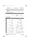
Step 1: Fit the insulation (1) around the reducer (2) and keep it in
place with tape ( ).
1
2
3
1
Joint or reducer
2
Cut in the center of the
connections.
3
Field pipe
Step 2: Cut the insulation (5) along the slit (4). Fit the insulation
around the joint (6) and keep it in place with tape ( ) (7) without
leaving a gap between the two insulated parts.
Step 3: Seal the seam between the insulation and the field piping
insulation ( ) with tape ( ) (8).
Step 4: Cover the insulated parts completely with tape (
leaving any gaps (9).
■
All required tape is field supply.
■
In case of indoor installation, make sure that the tape
is of the fireproof type in order to comply with local
regulations.
Installation manual
7
) without
BHFQ22P1007+1517
Outdoor unit multi connection piping kit
4PW28994-1