1
R
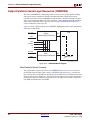
Input Serial-to-Parallel Logic Resources (ISERDES)
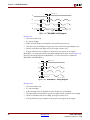
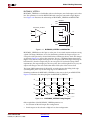
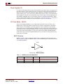
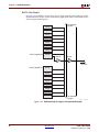
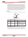
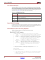
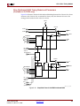
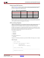
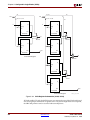
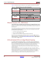
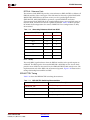
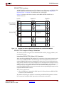
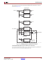
Guidelines for Using the Bitslip Sub-Module
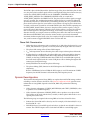
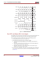
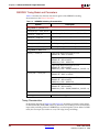
Set the BITSLIP_ENABLE attribute to TRUE. When BITSLIP_ENABLE is set to FALSE, the
Bitslip pin has no effect. In a master-slave configuration, the BITSLIP_ENABLE attribute in
both modules must be set to TRUE.
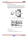
To invoke a Bitslip operation, the BITSLIP port must be asserted High for one and only one
CLKDIV cycle. In both SDR and DDR mode, the output pattern will be stable after two
CLKDIV cycles to become stable.
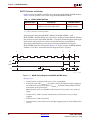
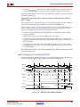
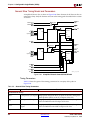
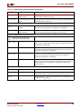
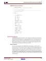
Bitslip Timing Model and Parameters
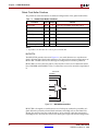
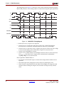
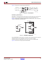
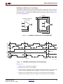
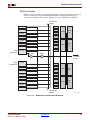
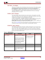
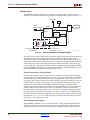
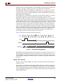
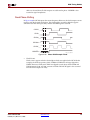
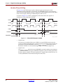
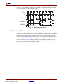
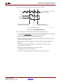
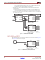
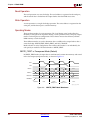
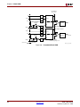
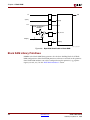
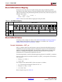
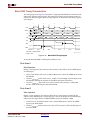
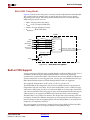
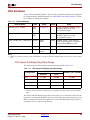
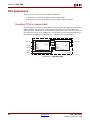
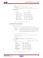
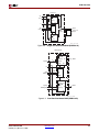
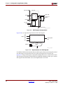
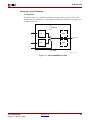
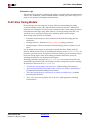
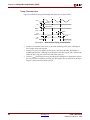
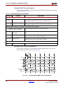
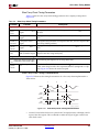
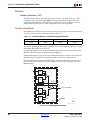
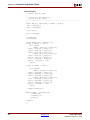
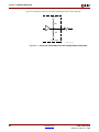
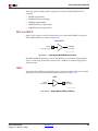
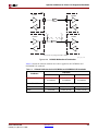
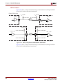
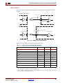
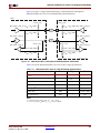
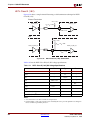
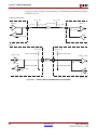
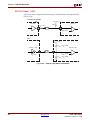
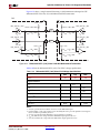
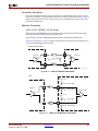
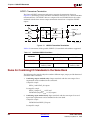
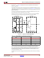
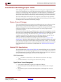
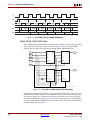
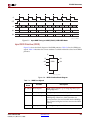
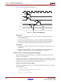
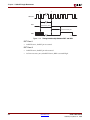
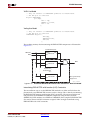
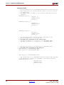
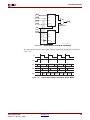
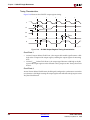
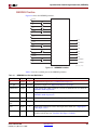
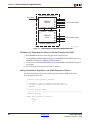
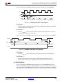
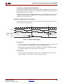
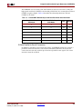
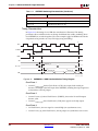
This section discusses the timing models associated with the Bitslip controller. Figure 8-9
shows the Bitslip timing diagram.
1
2
CLK
CLKDIV
D
Q1 to Q6, Q3 and Q4
of Master of Slave
MSB
LSB
TISCKOQ
10010011
11001001
TISCCK_BITSLIP
BITSLIP
ug070_8_18_072904
Figure 8-9: Bitslip Timing Diagram
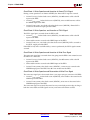
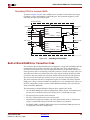
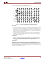
Clock Event 1
•
At time TISCCK_BITSLIP, before CLKDIV Event 1, the Bitslip signal is asserted High. On
the next CLKDIV cycle the ISERDES can perform a Bitslip operation.
•
Bitslip must be asserted for exactly one CLKDIV cycle. Holding the Bitslip pin High
for multiple CLKDIV cycles will produce incorrect results.
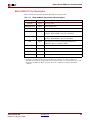
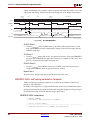
Clock Event 2
•
Virtex-4 User Guide
UG070 (v1.5) March 21, 2006
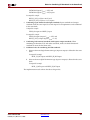
At time TISCKO_Q, after CLKDIV Event 2, at the next CLKDIV cycle after Bitslip has
been held High, a new output is available on the Q1 to Q6 bus.
www.xilinx.com
373