1
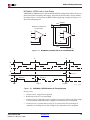
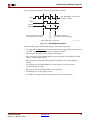
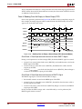
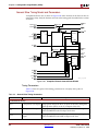
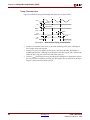
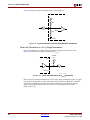
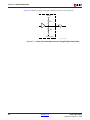
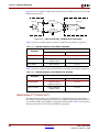
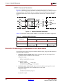
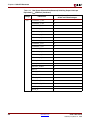
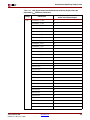
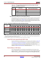
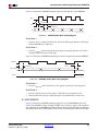
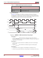
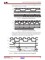
R
Chapter 2: Digital Clock Managers (DCMs)
The DCM is phase-shifted beyond the absolute range of the phase-shift delay line. In this
case, the phase-shift overflow signal will be assert High when the phase-shift in time (ns)
exceeds the ±FINE_SHIFT_RANGE/2 in the VARIABLE_CENTER mode, the
+FINE_SHIFT_RANGE in the VARIABLE_POSITIVE mode, or exceeds 0 to
+FINE_SHIFT_RANGE in the DIRECT mode. The phase-shift overflow signal can toggle
once it is asserted. The condition determining if the delay line is exceeded is calibrated
dynamically. Therefore, at the boundary of exceeding the delay line, it is possible for the
phase-shift overflow signal to assert and de-assert without a change in phase shift. Once
asserted, it will remain asserted for at least 40 CLKIN cycles. If the DCM is operating near
the FINE_SHIFT_RANGE limit, do not use the phase-shift overflow signal as a flag to
reverse the phase shift direction. When the phase-shift overflow is asserted, de-asserted,
then asserted again in a short phase shift range, it can falsely reverse the phase shift
direction. Instead, use a simple counter to track the phase shift value and reverse the phase
shift direction (PSINCDEC) only when the counter reaches a previously determined
maximum/minimum phase shift value. For example, if the phase shift must be within 0 to
128, set the counter to toggle PSINCDEC when it reaches 0 or 128.
Phase-Shift Characteristics
•
Offers fine-phase adjustment with a resolution of ±1/256 of the clock period (or ± one
DCM_TAP, whichever is greater). It can be dynamically changed under user control.
•
The phase-shift settings affect all nine DCM outputs.
•
VCC and temperature do not affect the phase shift except in direct phase-shift mode.
•
In either fixed or variable mode, the phase-shift range can be extended by choosing
CLK90, CLK180, or CLK270, rather than CLK0, choosing CLK2X180 rather than
CLK2X, or choosing CLKFX180 rather than CLKFX. Even at 25 MHz (40 ns period),
the fixed mode coupled with the various CLK phases allows shifting throughout the
entire input clock period range.
•
MAX_RANGE mode extends the phase-shift range.
•
The phase-shifting (DPS) function in the DCM requires the CLKFB for delay
adjustment.
Because CLKFB must be from CLK0, the DLL output is used. The minimum CLKIN
frequency for the DPS function is determined by DLL frequency mode.
Dynamic Reconfiguration
The Dynamic Reconfiguration Ports (DRPs) can update the initial DCM settings without
reloading a new bit stream to the FPGA. The Virtex-4 Configuration Guide provides more
information on using DRPs. Specific to the DCM, DRPs can perform the following
functions:
•
Allow dynamic adjustment of CLKFX_MULTIPLY(M) and CLKFX_DIVIDE(D) value
to produce a new CLKFX frequency.
•
Allow dynamic adjustment of PHASE_SHIFT value to produce a new phase shift.
This feature can be used with the fixed, variable, or direct phase-shift modes to set a
specific phase-shift value.
The following steps are required when using DRPs to load new M and D values:
76
•
Subtract the desired M and D values by one. For example, if the desired M/D = 9/4,
then load M/D = 8/3.
•
Hold DCM in reset (assert RST signal) and release it after the new M and D values are
written. The CLKFX outputs can be used after LOCKED is asserted High again.
www.xilinx.com
Virtex-4 User Guide
UG070 (v1.5) March 21, 2006