1
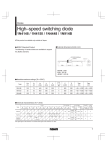
Contents
Safety Precaution
Important safeguards
Looking after your Smoke Check
Introduction
Before you begin
Smoke Check system overview
CO sensor
Smoke Check exploded view
Disassembling the Smoke Check
meter for servicing
Replacing the internal battery
Replacing the fuel cell
Reassembling the Smoke Check
Calibrating the Smoke Check
Circuit description
Power supply
Fuel cell conditioning circuit
Fuel cell amplifier
A/D converter
Reset circuit
Display
Sounder
Indicator lights
RS232 interface
Specifications
Technical support
Parts List
Circuit Diagram
ON
OFF
sm oke
Smoke Check
Service Manual
041-08 Iss. 1.0
page
September 2000
2
2
2
2
2
3
5
6
7
7
7
8
9
11
11
12
12
12
13
13
13
13
14
14
15
16
18
Smoke Check
Service Manual
Information in this document is subject to change without notice and does not represent a commitment
on the part of Micro Medical Limited. Only the parts supplied by Micro Medical Limited should be used
to complete the service operation described in this manual. If in any way you feel unsure about the
successful completion of the service operation you should contact Micro Medical Limited or its
appointed agent in your country or region and arrange the despatch of the product to a Micro Medical
Limited Service Centre.
Copyright 2000 by Micro Medical Limited All rights reserved
Drawing no. 041-08
Version 1.0
September 2000
All other products are trademarks or registered trademarks of their respective owners.
1
Safety Precaution
The servicing of this device is intended to be carried out by a properly trained and
competent electronics engineer, or experienced in the maintenance and servicing
of medical devices. Read this manual thoroughly before proceeding with the
service. If in any doubt please contact the service centre at Micro Medical Limited
or their accredited agent in your country or region.
Important Safeguards
ο Read all of the instructions.
ο Keep the instructions in a safe place for later use.
ο Follow all warnings and instructions marked on the product.
ο When replacement parts are required, be sure to use replacement parts
specified by Micro Medical that have the same characteristics as the original
parts. Unauthorised substitutions may result in fire, electric shock or other
hazards.
ο Do not place on an unstable table.
ο The product should be operated only from the type of power source indicated
on the label.
Looking after your Smoke Check
ο Avoid exposing the Smoke Check to direct sunlight.
ο Avoid operating the Smoke Check in dusty conditions or near to heating
appliances or radiators.
ο Do not keep the Smoke Check in a damp place or expose it to extreme
temperatures.
Introduction
This service manual provides you with information to carry out the servicing of the
Smoke Check. It is a process, which is relatively straightforward but must be
carried out in a logical sequence. Our advice is to familiarise yourself with the
contents of this manual before attempting to carry out the procedure of replacing
the parts supplied in the sensor replacement kit for the Smoke Check.
Before You Begin
Before you begin the servicing operation, please read the section on Circuit
description very carefully:
2
Smoke Check system overview.
The Micro Medical Smoke Check consists of a hand held microcomputer
unit (1) incorporating a CO sensor and is supplied with a mouthpiece
adapter with integral one way valve and flow restrictor (2) together with
disposable cardboard mouthpieces (5).
The microcomputer unit is powered by a single alkaline PP3 battery (4)
and is supplied with a reducing connector (3) and rod (6) for calibration
1
2
3
ON
OFF
4
sm oke
5
6
3
The CO sensor is an electrochemical fuel cell, and works through the
reaction of carbon monoxide at one electrode and oxygen (from ambient
air) at the other. This reaction generates an electrical current proportional
to the concentration of CO exposed to the sensing surface of the fuel cell.
The current output signal from the sensor is conditioned using a current to
voltage converter and is applied to an analogue port of the
microprocessor.
When the unit is first switched on the microprocessor records the baseline
analogue reading and uses this value to auto zero the instrument.
The subject is then requested to breathe in maximally, hold the breath for
20 seconds, and then to expire fully through the mouthpiece connected to
the Smoke Check with the mouthpiece adapter. As an aid to timing the
breath holding period the legend ‘WAIT’ is displayed until the 20 seconds
has elapsed.
The microprocessor then records the peak value obtained and displays
this on a custom LCD display in the ranges given below.
As a quick guide to the estimated smoking level, red, amber and green
indicator lights are also provided. The following levels of CO activate
these lights:
CO(ppm)
0-6
7 -10
11 – 20
20+
Cigarette consumption
Non smoker
Light smoker
Heavy smoker
Very heavy smoker
4
Indicator
Green
Amber
Red
Flashing red + alarm
CO Sensor
The sensor is an electrochemical micro fuel cell using gaseous diffusion
barrier technology resulting in a direct response to volume concentration
rather than partial pressure as with other fuel cells.
The cell has two electrodes, a counter electrode and a working electrode
separated by a thin layer of electrolyte. The gaseous diffusion barrier
limits the flow of gas to the sensing electrode and ensures the
electrochemical activity of the electrode is far in excess of the amount of
gas with which it has to deal.
Gas diffusing onto the sensing electrode reacts at the surface of the
electrode by oxidation.
CO reacts at the sensing electrode according to the equation:
CO + H2O → CO2 + 2H+ + 2eThe counter electrode acts to balance out the reaction at the sensing
electrode by reducing oxygen in air to water:
½O2 + 2H+ + 2e- → 2 H2O
5
Smoke Check exploded view
ITEM 1
ITEM 2
ITEM 3
ITEM 4
ITEM 5
ITEM 6
ITEM 8
ITEM 7
6
Disassembling the Smoke Check for servicing.
The Smoke Check microcontroller unit comprises of a solid state electronic
circuit in a robust ABS housing and does not require any preventative
maintenance.
Routine maintenance consists of replacing an exhausted fuel cell. The fuel
cell exhibits a gradual loss of sensitivity with time and has effectively expired
when the unit can no longer be calibrated.
When the fuel cell has expired, replace by following the procedure below.
1. Turn the unit face down and slide back the battery compartment.
2. Remove the PP3 battery.
3. Remove the 2 self tapping screws (Item 1) and put to one side.
4. Lift the top moulding (Item 6) from the bottom moulding (Item 2).
5. Remove the PCB (Item 3) from the bottom moulding.
6. Carefully remove the fuel cell (Item 4) by gently pulling away from the
PCB.
Replacing fuel cell of the Smoke Check.
1 Remove the CO sensor (Cat No: CEL4100) from the plastic container.
2 Insert the new cell into the PCB.
Reassembling the Smoke Check
1. Place the PCB into the bottom moulding.
2. Tuck the battery strap between the battery and the side wall of the bottom
moulding, away from the slide switch.
3. Ensure that the slide switch (item 7) and the switch plate on the top
moulding (item 8) are both positioned at the bottom of their travel.
4. Place the top moulding on top of the bottom moulding and secure using
the two self-tapping screws.
5. Reconnect the PP3 battery ensuring correct polarity.
7
Calibrating the CO meter
Plastic Tubing
Control
Valve
Flow
Indicator
Reducing Connector
for Calibration
20 ppm
carbon monoxide
in air
1. Set up the calibration equipment as shown above.
8
2. Locate the calibration button positioned on the right hand side of the
Smoke Check:
Calibration
button
3. Turn the Smoke Check on and wait for the unit to display ‘BLOW’.
4. Supply a flow of 20 ppm CO in air at a rate of approximately 0.25 l/min for
25 seconds.
5. Depress the calibration button, using the rod supplied, and three short
beeps will be heard as the calibration is recorded.
6. The unit is now ready for operation.
9
Circuit description
(Refer to the parts list and circuit diagram)
The circuit is based on the Microchip one time programmable (OTP) PIC
controller, PIC16C711 (U2) operating at a clock frequency of approximately 4
MHz.
This processor contains 1 Kbytes of EPROM, 68 Bytes of RAM, 13
programmable I/O pins, and a 4 channel 8-bit analogue to digital converter
(A/D). The current output signal from the sensor is conditioned using a
current to voltage converter, offset to 1.25 volts above power ground, and is
applied to an A/D port of the controller. Voltage derived the external PP3
battery are also connected to an A/D port.
When the unit is first switched on the microprocessor records the baseline
reading from the A/D and uses this value to auto-zero the instrument. The
signal from the CO sensor is continuously monitored and the peak of the
calculated carbon monoxide concentration recorded and the relevant range is
displayed. The signal representing the battery voltage is only monitored once
when the unit is switched on.
Power Supply
The externally accessible alkaline 9 volt PP3 battery (BAT 1) provides the
power supply. The switch (SW1) controls the battery supply with reverse
polarity protection provided by D6. The low drop-out regulator, U3, and
associated smoothing capacitors (C3, C4, C6 and C7) provides 5 volts (VDD)
to the circuit. The battery voltage is monitored by analogue channel 2 (pin 1)
of the controller. The battery voltage halved by R11 and R12 to bring the
voltage within the range of the A/D port (5 volts).
Fuel cell amplifier circuit.
The fuel cell provides an output current, from the working electrode,
proportional to the concentration of target gas at the sensing surface. This
current is converted to a voltage by the action of U1 and the associated
passive components at a transfer factor of 2.1 mV/nA. The feedback
network consisting of R1, R2, C1 and the thermistor TH1 provide signal
filtering and temperature compensation. R3 is not used and the link is cut.
The output of U1 is applied to analogue channel 3 (pin2) of the controller.
The sensitivity of the CO fuel cell is 0.03 +/- 0.06µA giving a nominal
output of 94.5 mV/ppm CO.
10
Reset Circuit
This consists of D1, R4, R5 and C2. Upon switch on this circuit provides a
delayed rise to the reset (pin 4) of the controller. The diode ensures rapid
discharge of the capacitor upon switch off.
Oscillator Circuit
A RC oscillator circuit is formed by R16 and C8 connected to pin 16 of the
controller, which provides the clock frequency.
Please note that the capacitance of the circuit tracks in the oscillator
section adds to that of C8 to obtain the correct clock frequency of 4 MHz.
Display
The display is a custom low power LCD. The legends are controlled by
square waves produced by port B of the controller (pins 6 to 13). The
backplane is driven by a square wave of nominally 60Hz from port A (pin
17). The individual legends are driven by a similar square wave that is in
phase with the backplane when the segment is off and 180 degrees out of
phase when the segment is on.
Indicator lights
The three indicator LED’s, together with a current limiting resistor and
reverse voltage blocking diode, are connected between their
corresponding legends on the display and the backplane. Only when a
legend is activated will a square wave appear across the LED circuit.
EEPROM
The calibration value is stored in a 1K serial EEPROM, U4. U4 is
activated when pin 18 of the controller is set high. The CLOCK and DATA
lines are controlled by the microprocessor’s pins 13 and 12 respectively.
The binary calibration value is written to the EEPROM only when the
calibration button is pressed, and is retreived from EEPROM every time
the unit is switched on.
Sounder
The sounder is operated by a 800 Hz square wave generated by pin 18.
11
Calibration switch
The switch SW2 pulls pin 3 to ground when pressed. This pin is polled by
the microprocessor and a logic low signals that the current input value
should be stored as the calibration value.
Specifications
Sensor type
Range
Detected levels:
0 to 6ppm
7 to 10ppm
11 to 20ppm
>20 ppm
Accuracy
Sensitivity drift
Sensor life
Response time
Hydrogen cross
sensitivity
Operating
temperature
Operating pressure
Pressure coefficient
Relative humidity
(Non condensing)
Baseline drift
Long term drift
Power source
Battery life
Weight
Dimensions
Display
Storage temperature
Storage humidity
Electro-chemical fuel cell
0 - 20 ppm
Display:
0-6 ppm with green indicator
7-10 ppm with amber indicator
11-20 ppm with red indicator
20+ ppm with red indicator +
alarm
+/-5% of full scale or 1ppm
whichever is the greater
0.5%/OC
2 to 5 years
< 15 sec (to 90% of reading)
<15%
15 - 25 OC
Atmospheric +/- 10%
0.02% signal per mBar
15 - 90% continuous
(0 - 99% intermittent)
0ppm (auto-zero)
< 2% signal loss per month
Single Alkaline 9 volt PP3
> 8000 tests
130g without battery
170 x 60 x 26 mm
Custom LCD
-20O to +70O
30% to 75%
12
Technical Support
Great Britain and World Headquarters
Micro Medical Ltd
PO Box 6
Rochester
Kent ME1 2AZ
Telephone
+ 44 (0)1634 360044
Fax
+44 (0)1634 360055
Web Site
http://www.micromedical.com.uk
Email
[email protected]
Contact Micro Medical Ltd for the local agent in your region or
country for local service:
13
Parts List
Designation
C1
C2
C3
C4
C5
C6
C7
C8
CO CELL
D1
D2
D3
D4
D5
D6
DISPLAY
LED1
LED2
LED3
R1
R2
R3
R4
R5
R6
R7
R8
R9
R10
R11
R12
R13
R14
R15
R16
R17
SK1
SK2
SPKR
SW1
SW2
TH1
TR1
U1
U2
U3
U4
Description
0.1µF CERAMIC CAPACITOR 0.1” LEAD SPACING
(667-470) 10uF ELECTROLYTIC CAPACITOR
(667-419) 100uF ELECTROLYTIC CAPACITOR
(667-470) 10uF ELECTROLYTIC CAPACITOR
33pF CERAMIC CAPACITOR 0.1” LEAD SPACING
0.1µF CERAMIC CAPACITOR 0.1” LEAD SPACING
0.1µF CERAMIC CAPACITOR 0.1” LEAD SPACING
22pF CERAMIC CAPACITOR 0.1” LEAD SPACING
(MID1-40) 1000 ppm CO CELL FROM SIXTH SENSE
(1N4448) SMALL SIGNAL DIODE
(1N4448) SMALL SIGNAL DIODE
(1N4448) SMALL SIGNAL DIODE
(1N4448) SMALL SIGNAL DIODE
(1N4448) SMALL SIGNAL DIODE
(1N4448) SMALL SIGNAL DIODE
(041-06) CUSTOM DISPLAY
(637-129) KINGBRIGHT 3mm GREEN LED
(322-507) HP HLMP1440 3mm YELLOW LED
(637-142) KINGBRIGHT 3mm RED LED
100K 0.25 WATT 5% CARBON FILM RESISTOR
1M 0.25 WATT 5% CARBON FILM RESISTOR
NOT USED
1K 0.25 WATT 5% CARBON FILM RESISTOR
39K 0.25 WATT 5% CARBON FILM RESISTOR
820 OHM 0.25 WATT 5% CARBON FILM RESISTOR
820 OHM 0.25 WATT 5% CARBON FILM RESISTOR
820 OHM 0.25 WATT 5% CARBON FILM RESISTOR
10K 0.25 WATT 5% CARBON FILM RESISTOR
1K 0.25 WATT 5% CARBON FILM RESISTOR
10K 0.25 WATT 5% CARBON FILM RESISTOR
10K 0.25 WATT 5% CARBON FILM RESISTOR
10K 0.25 WATT 5% CARBON FILM RESISTOR
1K 0.25 WATT 5% CARBON FILM RESISTOR
10K 0.25 WATT 5% CARBON FILM RESISTOR
5K6 0.25 WATT 5% CARBON FILM RESISTOR
10K 0.25 WATT 5% CARBON FILM RESISTOR
(450-1804-01-03-00) SOCKET FROM CAMBION
(450-1804-01-03-00) SOCKET FROM CAMBION
(PT-1550W) DAU COMPONENTS PIEZO CERAMIC SOUNDER
(SLF2300) DOUBLE POLE 3 POSITION SLIDE SWITCH
(312-1100) MULTICOMP PUSHBUTTON SWITCH
(DKD105NS) THERMOMETRIC 1MEG THERMISTOR
(TC04BCZM) 1.25V PRECISION BANDGAP REFERENCE
(OP90G) 8-PIN DIL PRECISION OP-AMP
(PIC16C711 04/P) OTP MICROCONTROLLER
(LM2931M5.0) LOW DROP OUT SURFACE MOUNT 5 VOLT REGULATOR
(24LC01) MICROCHIP 1K SERIAL CMOS EEPROM
14