1
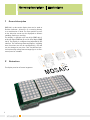
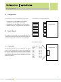
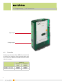
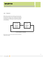
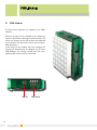
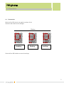
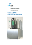
User Manual DMD 50
Kapitelbezeichnung
Kapitelbezeichnung
X.X Unterpunkt
SCHAEFER GmbH
Winterlinger Str. 4
72488 Sigmaringen
Germany
Phone +49 7571 722-0
Fax +49 7571 722-99
[email protected]
www.ws-schaefer.de
Support
If you have any questions regarding this product please contact:
Phone +49 7571 722-51
Fax +49 7571 722-99
Copyright
Duplication (copy, print, microfilm or any other form) as well
as electronic spreading of this document
is only permitted after formal writting consent of SCHAEFER GmbH.
SCHAEFER GmbH reserves the right to carry out alterations
of technical details without prior notice.
For all transactions our General Conditions of Sale
and Delivery shall be applicable.
All rights reserved.
Ress. 010952
Revision: 2010-02-12
2
Index
User Manual Dot-Matrix Display DMD 50
Index
1
General description ................................. 4
2
Illustrations .............................................. 4
3
Configuration ........................................... 5
4
4.1
4.2
4.3
4.4
4.4.1
4.4.2
Input Module . ........................................... 5
Programming .......................................................5
Connection ...........................................................6
Additional Encoder? ..........................................7
Settings .................................................................8
Coding ...................................................................8
Connection ...........................................................9
5.
5.1
5.2
5.3
PMD-Module ........................................... 10
Presentation ......................................................11
Frequency .......................................................... 12
Brightness/Intensity ....................................... 13
6.
Technical Data ........................................14
7.
Models .....................................................15
3
Gerneral description | Illustrations
1 General description
DMD 50 is a dot-matrix display that can be used as
Position Indicator-, direction- or re-starting Arrows,
or a combination of both. The floor position as well
as the direction arrows can be displayed as follows:
standing, flashing or scrolling.
The display is available with one digit (DMD 50-1),
with two digits (DMD 50-2) or with three digits (DMD
50-3). The display is configured and adjusted by DIP
switches. The indicating characters/figures, including
there functions can also be configured by a PC and
can be changed at any time. Two free-defined special horizontally rolling texts messages (up to 14 characters) can be included.
2 Illustrations
The display consists of several segments.
4
Configuration | Input-Module
4.1 Programming
3 Configuration
Two different kinds of configuration are possible:
-
-
Configuration of the DMD 50 at SCHAEFER
according to the customer requirement
Configuration of the DMD 50 on site. Therefore
a DMD-Config Kit is needed (article No. 010575).
4 Input-Module
The display is connected via the Input Module. This
module has a two-pole terminal for the voltage supply and an eight-pole terminal for the signal input.
Schraubklemme / Federkraftklemme
8
7
6
5
4
3
2
1
travel
down
up
Adr. 4
Adr. 3
Adr. 2
Adr. 1
Adr. 0
Input-Module
GND
12 V - 30 V
Micro Match Buchse
4.1 Programming
The following seizure of the terminals of the signal
input is to be considered as a general presetting. Due
to the free configuration, the seizure can be changed.
In order to show special text messages, the terminals
must be defined as special text messages by using the
DMD-Configurator.
12 V - 30 V
Adr. 0
Adr. 1
Adr. 2
Adr. 3
Adr. 4
up
down
GND
travel
Pin 1
Pin 2
Pin 3
Pin 4
Pin 5
Pin 6
Pin 7
Pin 8
Pin 9
Pin 10
Input-Module
5
Input-Module
4.1 Programming | 4.2 Connection
Signal input
Voltage supply
4.2 Connection
Usually, the connection of the DMD 50 is made via the
terminals. For a signal per floor connection with more
than 5 floors, an additional Encoder PCB with ribbon
cable is necessary.
Encoder 1 out of 15
Encoder 1 out of 31
6
Article Nr.
Common
Common
anode
cathode
008808
008809
008806
008807
Input-Module
4.3 Additional Encoder ?
4.3 Additional Encoder ?
Die folgende Tabelle zeigt eine Übersicht, wann zusätzlich ein Encoder verwendet werden muss. Je nach Anzahl
der Lauftexte und Etagen können Pfeile mit/ohne Fahrtsignal konfiguriert und vom Display angezeigt werden.
Horizontally
Rolling
Messages
none
1
2
3*
4*
Coding (control)
Floors
Dual/Gray
up to 5
6 up to 15
16 up to 31
up to 4
5 up to 15
16 up to 31
up to 3
4 up to 7
8 up to 15
16 up to 31
up to 2
3
4 up to 7
8 up to 15
16 up to 31
up to 2
3
4 up to 7
8 up to15
16 up to 31
1 out of n (signal per floor)
-
Encoder 1 out15
Encoder 1 out31
Encoder 1 out15
Encoder 1 out31
Encoder 1 out15
Encoder 1 out15
Encoder 1 out31
Encoder 1 out15
Encoder 1 out15
Encoder 1 out15
Encoder 1 out15
Encoder 1 out15
Encoder 1 out15
Encoder 1 out15
nicht möglich
Display
possibilities
Arrows Travelling
yes
yes
yes
yes
yes
yes
yes
yes
yes
no
yes
yes
yes
no
no
yes
yes
no
no
yes
yes
yes
yes
yes
no
yes
yes
no
no
yes
yes
no
no
no
no
no
no
no
* Mehr als zwei Sondertexte erst ab SW-Version 1.5 auf der DMD 50 möglich.
Note: When using an Encoder PCB (Signal per
floor), the DMD display must be configured for
Dual coding.
7
Input-Module
4.4 Settings | 4.4.1 Coding
4.4 Settings
Different settings can be changed on the display by
means of the buttons and respective DIP switches. The
values are changed by the DIP switches and adjusted
by the buttons. The status LED show the corresponding setting. The setting is saved after the corresponding DIP switch has been turned off.
Status LED
Button
DIP switch (4-pole)
4.4.1 Coding
With DIP switch 1 the coding type of the display can
be adjusted. By pressing the button the different coding type can be selected.
LED: yellow
Dual
Button
LED: green
Button
Gray
At the touch of a button
8
LED: yellwo
green
1 out of n
Input-Module
4.4.2 Connection
4.4.2 Connection
DIP switch 2 controls the switching variant. By switching the DIP switch to the on position and pressing
the button, the module can be switched to common
cathode (positive switching) or common anode (negative switching).
LED: yellow
Butto
common
cathode
LED: green
common
anode
At the touch of a button
DIP switches 3 and 4 are reserved for later functions
and have no effect.
9
PMD-Module
5 PMD-Module
The dot-matrix segments are clipped-on the PMDmodules.
Different settings can be changed on the display by
means of the buttons and respective DIP switches. The
values are changed by the DIP switches and adjusted
by the buttons. The dot-matrix shows the corresponding adjustment.
If the setting of one module has been changed, this
setting will automatically be adopted by the other
PMD Modules. The setting is saved after the corresponding DIP switch has been turned off.
Button DIP switch
10
PMD-Module
5.1 Presentation
5.1 Presentation
With the first DIP switch, the graphic versions of the
character and arrows can be changed.
Button
standing
flashing
scrolling
Switch off the DIP switches to save the settings.
11
PMD-Module
5.2 Frequency
5.2 Frequency
With the second DIP switch, the flashing or scrolling
frequency can be adjusted, this only applies if the
Flashing or Scrolling mode is selected. This DIP switch
has no function, if the “Standing“ mode is applied.
Button
Presentation
12
scrolling
8 Z/sec
10 Z/sec
12 Z/sec
14 Z/sec
16 Z/sec
flashing
2 Hz
4 Hz
6 Hz
8 Hz
10 Hz
PMD-Module
5.3 Brightness/Intensity
5.3 Brightness/Intensity
With the third DIP switch, the brightness can be changed by pressing the button.
Button
50%
60%
70%
80%
100%
DIP switch 4 is reserved for later functions and has no
effect.
13
Technical Data
6 Technical Data
Supply voltage:
12 – 30 V (DC, smoothed current)
Current requirement:
1-digit: up to 60 mA
2-digits: up to 105 mA
3-digits: up to 150 mA
Temperature range:
up to + 65 °C/149 °F
Luminosity:
red: 49 mcd
green: 200 mcd
blue: 40 mcd
Addressing 1 out of n:
up to 8 floors; with additional encoder up to 31 floors
Addressing binary/Gray:
up to 31 floors
Connection
via terminal:
rigid or flexible up to 1,5 mm2
(flexible with wire end ferrules
and plastic sleeves (0,5 mm2)
Connection
via push-in terminal:
rigid or flexible up to 1,5 mm2
(flexible with wire end ferrules
and plastic sleeves (0,75 mm2)
In conformity with:
14
Models
8 Models
As well as the standard, other models are available:
• splash-proof model IPX3 according to EN 81-72
(temper proof model for category 1 according to EN 81-71)
In conformity with:
15