1
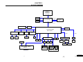
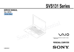
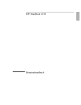
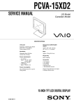
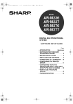
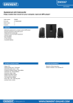
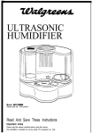
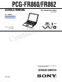
PCG-FR860/FR862
SERVICE MANUAL
For American Area
Latin Model
Ver 1-2003G
Revision History
Lineup : PCG-FR862
PCG-FR860
Illust : PCG-FR862
l
a
i
t
n
S400
e
d
i
f
n
o
C
• Design and specifications are subject to
change without notice.
NOTEBOOK COMPUTER
9-876-305-01
Information in this document is subject to change without notice.
Caution Markings for Lithium/Ion Battery - The following or similar
texts shall be provided on battery pack of equipment or in both the
Sony, VAIO and CLIE are trademarks or registered trademarks of
Sony. Microsoft, Windows, Windows Media, Outlook, Bookshelf
operating and the service instructions.
and other Microsoft products are trademarks or registered trademarks
of Microsoft Corporation in the United States and other countries.
CAUTION: Danger of explosion if battery is incorrectly replaced.
Replace only with the same or equivalent type recommended by
The word Bluetooth and the Bluetooth logo are trademarks of
Bluetooth SIG, Inc. AMD, the AMD logo, other AMD product names
the manufacturer. Discard used batteries according to the
manufacturer’s instructions.
and combinations thereof are trademarks of Advanced Micro
Devices, Inc. Intel Inside logo, Pentium and Celeron are trademarks
CAUTION: The battery pack used in this device may present a fire
or registered trademarks of Intel Corporation. Transmeta, the
Transmeta logo, Crusoe Processor, the Crusoe logo and
or chemical burn hazard if mistreated. Do not disassemble, heat
above 100°C (212°F) or incinerate.
combinations thereof are trademarks of Transmeta Corporation in
the USA and other countries. Graffiti, HotSync, PalmModem, and
Dispose of used battery promptly.
Keep away from children.
Palm OS are resistered trademarks, and the Hotsync logo and Palm
are trademarks of Palm, Inc. or its subsidiaries. (M) and Motrola
CAUTION: Changing the back up battery.
are trademarks of Motrora, Inc. Other Motrola products and services
with (R) mark like Dragomball are the trademarks of Motrola, Inc.
• Overcharging, short circuiting, reverse charging, multilation or
incineration of the cells must be avoided to prevent one or more of
All other names of systems, products and services in this manual
the following occurrences; release of toxic materials, release of
hydrogen and/or oxygen gas, rise in surface temperature.
are trademarks or registered trademarks of their respective owners.
In this manual, the (TM) or (R) mark are not specified.
• If a cell has leaked or vented, it should be replaced immediately
while avoiding to touch it without any protection.
Service and Inspection Precautions
1. Obey precautionary markings and instructions
4. Inspect after completing service
Labels and stamps on the cabinet, chassis, and components identify areas
requiring special precautions. Be sure to observe these precautions, as well
as all precautions listed in the operating manual and other associated
documents.
After servicing, inspect to make sure that all screws, components, and wiring
have been returned to their original condition. Also check the area around
the repair location to ensure that repair work has caused no damage, and
confirm safety.
2. Use designated parts only
5. When replacing chip components...
The set’s components possess important safety characteristics, such as
noncombustibility and the ability to tolerate large voltages. Be sure that
replacement parts possess the same safety characteristics as the originals.
Also remember that the 0 mark, which appears in circuit diagrams and
parts lists, denotes components that have particularly important safety
functions; be extra sure to use only the designated components.
Never reuse components. Also remember that the negative side of tantalum
capacitors is easily damaged by heat.
3. Always follow the original design when mounting
parts and routing wires
6. When handling flexible print boards...
• The temperature of the soldering-iron tip should be about 270C.
• Do not apply the tip more than three times to the same pattern.
• Handle patterns with care; never apply force.
The original layout includes various safety features, such as inclusion of
insulating materials (tubes and tape) and the mounting of parts above the
printer board. In addition, internal wiring has been routed and clamped so
as to keep it away from hot or high-voltage parts. When mounting parts or
routing wires, therefore, be sure to duplicate the original layout.
Caution: Remember that hard disk drives are easily damaged by
vibration. Always handle with care.
Confidential
—2—
PCG-FR860/FR862 (AM)
TABLE OF CONTENTS
Section
Title
Page
CHAPTER 1. BLOCK DIAGRAM ............................... 1-1
(to 1-2)
CHAPTER 2. FRAME HARNESS DIAGRAM ........ 2-1
(to 2-2)
CHAPTER 3. EXPLODED VIEWS AND
PARTS LIST ............................................ 3-1
3-1. Main Section .................................................................... 3-2
3-2. LCD Section – Made by HI – .......................................... 3-5
(to 3-6)
CHAPTER 4. OTHERS
4-1. Replacing the CPU .......................................................... 4-1
1. Removing the CPU .......................................................... 4-1
2. Installing the CPU ............................................................ 4-1
History of the changes is shown as the
“Revision History” at the end of this data.
Confidential
—3—
PCG-FR860/FR862 (AM)
CHAPTER 1.
BLOCK DIAGRAM
Intel
Pentium 4
Celeron
478 PIN mPGA
System bus
400/533MHz
R/G/B
CRT
LVDS SIGNAL
NORTH BRIDGE
DRAM SIGNAL
LCD
TV SIGNAL
ATI RS200M+
DDR 266
SO-DIMM 1/2
DDR CLOCK
AVOUT
P C I b us(Mux with A-link)
266MB/s
Memory Stick Board
LPC
Connector
RTC
TIBQ3285LF
PCI BUS
South Bridge
ALI 1535+
Realtek
RTL8100BL
VIA
VT6202AL
SLOT0/1
RJ45
1394
USB*3
CDROM
AC LINK1
XBUS
USB 2.0
PRIMARY IDE BUS
CARDBUS+1394LINK/PHY
Mini PCI
Wirless LAN
SECONDARY IDE BUS
RICOH 5C554
AD1981B
PCU
LPT
NS PC87570
EXT.MIC.
INT.K/B
TPA0142
BATTERY
T/P SWITCH
T/P BOARD
RJ11
BIOS
EXT.SPKR.
MAIN POWER BOARD
PWS-29
MDC
FDD
HDD
TOUCH
PAD
DC JACK
AC LINK2
POWER SWITCH
Bettery LED
INT.SPKR.
Power LED
K/B LED
Power SW BOARD
Confidential
1-1
1-2
(END)
PCG-FR860/FR862 (AM)
CHAPTER 2.
FRAME HARNESS DIAGRAM
NETWORK
USB
LCD Block
PRINTER
MONITOR
PHONE
Rear Panel
LCD
LCD HARNESS
INVERTER
L Side
CON9
CON22
CON5
CON10
CON8
22
1
21
CON16
CON24
CON13
29
USB
MBX-88 Board
(Side-A)
2
CON6
AV OUT
30
USB
CON1
DC FAN
JP3
CON2
200
A1
199
124
2
200
2
199
DC FAN
CON12
2
59
1
Optical DRIVE
PCN2
CON7
FLOPPY DISK DRIVE
26
27
PCN1
2
1
29
30
J2
J1
8
7
1
59
1
KEY BOARD
CON1
1
12
2
JP1
JP2
1
1
1
CON2
8
PCN3
14
CARD, MODEM
PCN2
2
60
MEMORY STICK
1
2
1
2
CON23
1
60
52
CON29
2
48
24
2
14
25
CON21
A77
1
CON14
1
1
WIRELESS
LAN
13
DDR SO-DIMM
SLOT A
3
CON26
1
50
RAM
49
1
1
SWX-127 Board
(Side-A)
1
CON4
1
HARD DISK
1
CON3
Twin FAN Model
PC CARD
CONNECTOR
2
JP1
3
CON25
CON11
22
21
1
IEEE 1394 i.LINK
1
SPEAKER
2
CON18
2
HEADPHONE
1
2
CON19
1
CON15
EXTERNAL
MICROPHONE
BATTERY PACK
8
IFX-271 Board
(Side-A)
PAD, TOUCH
SWX-128 Board
(Side-A)
PCN4
From board to connector (direct connection)
Harness (connector at both end)
Harness (soldered at one end)
SW1
PWS-29 Board
(Side-A)
Connectors soldered on board and appearing on the panel
Confidential
2-1
2-2
(END)
PCG-FR860/FR862 (AM)
CHAPTER 3.
EXPLODED VIEWS AND PARTS LIST
NOTE:
• Items marked “ * ” are not stocked since they are seldom
required for routine service. Some delay should be
anticipated when ordering these items.
• The mechanical parts with no reference number in the
exploded views are not supplied.
• When two or more parts are shown, use the part described
first as the main part.
• The parts marked “ $ ” are the High Value Modules (HVM).
• The parts marked “ # ” are the parts on which
barcode label is attached.
• The parts marked “ & ” are the “Customer Replacable
Parts (CRP)” that can be replaced by Field Customer
Support.
Especially the parts with the <&> mark require the special
attention to use them. Here fore, check first whether the
desired part is one of the targetted parts of the Customer
Replaceable Parts(CRP), or the non-targetted parts by
referring to the exploded view.
• Regarding the boards of this model, the discrete parts
on the boards cannot be replaced. However, Some
connectors can be replaced.
The components identified by mark 0 or
dotted line with mark 0 are critical for safety.
Replace only with part number specified.
Les composants identifiés par une marque
0 sont critiques pour la sécurité.
Ne les remplacer que par une pièce portant
le numéro spécifié.
Confidential
3-1
PCG-FR860/FR862 (AM)
3-1. Main Section
Ref.No. Part No.
1
4-677-632-01
2
6-600-158-01
Description
INSULATOR BOTTOM
IC HYS64D32020GDL-7-B
(DDR DIMM 256MB)
IC M470L3224DT0-CB0
(DDR DIMM 256MB)
BRACKET KEYBOARD
INSULATOR PC CARD
2
6-600-116-01
* 10
12
4-674-025-01
4-677-636-01
13
15
1-761-695-11
6-704-957-01
15
6-704-132-01
16
17
A-8068-048-A $ #
1-756-148-11
NE5.1 PC CARD(EJECTER)
(FR860)...
IC RH80532NC049256SL73Y
(Mobile Celeron 2.2GHz)
(FR862)...IC RK80532PE067512SL6S3
(P4 2.66GHz)
COMPLETE PWB MBX-88
SECONDARY, BATTERY, LITHIUM
18
19
20
21
21
1-761-606-14 #
1-827-193-11
1-827-605-11
4-676-840-01 $
4-676-840-11 $
CARD, MODEM
NE5.1 CABLE(MDC-MBX)
JE1.1 FFC(PWR)
(FR860)...ID LABEL L
(FR862)...ID LABEL L
22
23
24
25
26
X-4626-183-1
1-825-426-11
4-644-357-01
4-654-631-01
4-671-631-01
HOOD KEYBOARD ASSY (S)
NE5.1 SPEAKER
CUSHION SPK
GUARD SPK
BRACKET SPEAKER
27
28
29
30
31
4-674-042-01
1-825-427-11
A-8067-868-A $
4-670-198-01
1-796-319-31
MEMORY STICK WINDOW
NE5.1 SPEAKER(R)
COMPLETE PWB SWX-128
ESCUSHION TOUCHPAD
PAD, TOUCH
32
* 33
34
35
36
4-672-077-01
ADHESIVE TAPE TP
4-674-023-01
BRACKET PALMREST L
1-478-086-81 $ # KEY BOARD UNIT (LA)
4-671-634-01
& CUSHION PALMREST
X-4626-182-1
HOUSING PALMREST ASSY (S)
* 37
38
39
40
* 41
4-674-022-01
A-8068-049-A $
1-827-189-11
1-827-192-11
4-674-024-01
BRACKET PALMREST R
COMPLETE PWB SWX-140
NE5.1 FFC(TP)
NE5.1 FFC(PWS-TP)
BRACKET TOUCHPAD
* 42
43
44
45
* 46
4-674-028-01
X-4626-113-1
1-796-627-11 $ #
4-670-244-01
4-674-029-01
BRACKET DRIVE R
ASSY QSI COMBO BEZEL
COMBO DRIVE (SBW-241)
SPRING DRIVE R
BRACKET (DRIVE) (L)
* 47
48
49
50
51
4-674-033-01
BRACKET HDD
A-8113-859-A $ # ASSY HDD 40GB (H) (S)
4-673-851-01
& COVER HDD
4-677-197-01
& FOOT FRONT
X-4626-185-1
& COVER MEMORY ASSY (S)
53
55
56
57
58
X-4626-186-1
X-4626-181-1
4-670-193-01
4-677-640-01
4-671-645-01
Ref.No.
59
60
61
* 62
* 63
Part No.
4-673-853-01
4-673-852-01
4-670-194-01
4-676-348-01
4-674-019-01
Description
& DOOR BATTERY
& COVER MODEM
COVER HOOD
BRACKET DC
PLATE DC
* 64
66
67
68
69
4-674-018-01
4-668-785-01
4-677-635-01
4-673-303-01
A-8068-050-A $
BRACKET IO
THERMAL SHEET CPU
INSULATOR PWS
SPACER TOUCHPAD BUTTON
COMPLETE PWB PWS-29
71
72
73
74
75
1-827-606-11
A-8068-051-A $
4-677-639-01
4-677-637-01
4-672-852-01
JE1.1 DC CABLE (INT)
COMPLETE PWB IFX-271
GASKET USB
CUPPER TAPE
SHEET HDD
76
77
78
79
81
4-672-855-01
1-860-222-11
4-672-858-01
4-674-041-01
4-672-849-01
GASKET SPEAKER
JE1.1 FPC (MS)
SHEET BRACKET TOUCHPAD
& FOOT REAR
GASKET LAN
82
* 83
84
4-671-635-01
4-674-030-01
A-8115-824-A $
84
A-8115-823-A $
85
4-673-615-01
& FOOT
GUIDE DRIVE
(FR862)...
ASSY COOLING UNIT (DTP) (S)
(FR860)...
ASSY COOLING UNIT (M) (S)
GASKET SPEAKER R
86
88
89
91
* 92
4-677-536-01
4-677-647-01
4-677-259-01
4-675-126-01
4-676-347-01
& SHEET RUBBER JE1
INSULATOR DRIVE
SPRING DRIVE L
CAP FDD
BRACKET DUMMY FDD
94
95
4-673-304-01
9-885-029-05
SPACER PC CARD
CONNECTOR, USB(A)
B1
B2
B3
B4
B5
4-216-272-01
4-635-966-01
4-641-726-12
4-641-726-41
4-644-637-01
SCREW
SCREW
<&> SCREW
SCREW
<&> GRIP,
B6
B10
B11
B12
B13
4-644-637-42
4-665-205-01
4-673-018-02
4-673-019-01
4-673-121-01
GRIP, M2 EG
<&> SPECIAL FLAT HEAD (EG GRIP),M2
SCREW SPECIAL HEAD
SCREW +B
SCREW PWS
B14
B15
4-673-655-01
4-650-481-01
& SCREW +B
& SCREW(B1.7),TAPPING
(M2), +
(HEX)
(M2), SPECIAL HEAD
(M2), SPECIAL HEAD
M2 EG
& COVER MINIPCI ASSY (S)
HOUSING BOTTOM ASSY (S)
LENS FDD
CUSHION HDD
& DOOR BATTERY SPRING
Confidential
3-2
PCG-FR860/FR862 (AM)
B12
B10
B5 B5
30
F
B1
34
B3 B5
B6
31
B12
J
33
84
A
32
F
B3
H
S
B5
32
B3
O
A
86
G
35
27
21
10
S
E
C
B6
C
R
B3
B3
K
I
86
66 (*2)
E
15 (*3)
13
24
B3
L
36
35
22
Supplied
with 36
23
92
83
*1
24
B4
81 95
73
12
20
19
B3
95
25
K
B3
76
T
B3
77
41
B3
B3
J
Supplied
with 16
17
B10
M
Q
L
72
B10
B3
N
D
68
39
B13
B
B10
29
40
61
69
16
P
*1 NOTE : Set the dip switch on the MBX-88
board (Main board) to match with
the CPU that is used in this
computer.
78
85
81
67
B3
M
38
28
26
U
B3
B3
94
18
B3
Q R 74
37
25
O
64
G
B14
56
H
91
B10
42
B1
2
1
B3
T
79
B
D
B2
63
B1
I
CPU: 6-704-132-01
IC RK80532PE067512SL6S3
B14
89
71
B10
B15
46
62
U
MB
P
Supplied
with 55
DT
44
79
55
CPU: 6-704-957-01
IC RH80532NC049256SL73Y
B10
B10 B5
B5
50
B5
57
58
B10
B3
B11
43
45
60
88
47
N
MB
DT
59
53
47
B3
*2 The THERMAL SHEET CPU (Ref. 66) cannot be re-used if it is removed once.
Supplied
with 51
51
B3
B3
48
B11
82
49
When the COOLING UNIT (Ref. 84) is removed, be sure to replace it with the new one.
B3
B3
*3 When change the CPU (Ref. 15), refer to “ Replacing the CPU ” in CHAPTER 4.
3-3
75
Confidential
3-4
PCG-FR860/FR862 (AM)
3-2. LCD Section – Made by HI –
301
302
304
303
B5
B4
B10
Supplied
with 304
B4
B4
306
Ref.No.
301
302
303
304
305
Part No.
4-671-639-01
4-671-637-01
4-671-638-01
X-4625-822-1
4-670-228-01
Description
& CUSHION HINGE
& CUSHION LATCH
& CUSHION LCD
BEZEL DISPLAY ASSY(15)(S)
BUTTON LATCH LCD
306
* 307
308
309
* 310
4-671-640-01
4-671-454-01
4-671-457-01
A-8113-852-A $ #
4-671-453-01
SPRING LATCH LCD
BRACKET LCD L (15)
HINGE L
ASSY LCD 15(H) GT2 (S)
BRACKET LCD R (15)
311
312
314
315
316
4-671-456-01
1-962-514-11
4-671-636-01
X-4625-820-1
1-476-317-21
HINGE R
LCD HARNESS
LCD SHIELDING
HOUSING DISPLAY ASSY(S)
INVERTER UNIT
317
4-673-299-01
INVERTER TAPE
B4
B5
B10
4-641-726-41
4-644-637-01
4-665-205-01
Ref.No. Part No.
0801
802
0803
1-478-037-12
A-8112-427-A
1-757-562-21
4-676-794-01
4-676-802-01
Description
ACCESSORIES
***********
$ & ADAPTOR, AC
$ # & BP2NX SNT (U) ASSY (S)
& CORD, POWER
$ & QUICK START 2670LAX/LBX
$ & SPEC SHEET (2670LAX/LBX)
801
803
AC Adaptor
Power Cord
<&> SCREW (M2), SPECIAL HEAD
& GRIP, M2 EG
SPECIAL FLAT HEAD (EG GRIP),M2
802
Battery Pack
305
309
307
NOTE :
Set the DIP switch on the MBX-88 board (Main board)
to match with the LCD that is used in this computer.
B4
308
ON
310
1 2 3 4 5 6
A
The upper position where ON indication is shown is the
ON position . The lower position is the OFF position.
B4
B10
1 2 3 4 5 6
ON/OFF 1 1 1 0 1 1
No.
312
311
B10
0 : ON
1: OFF
314
315
316
317
The components identified by
mark 0 or dotted line with mark
0 are critical for safety.
Replace only with part number
specified.
Les composants identifiés par
une marque 0 sont critiques
pour la sécurité.
Ne les remplacer que par une
pièce portant le numéro spécifié.
A
Confidential
3-5
3-6
(END)
PCG-FR860/FR862 (AM)
CHAPTER 4.
OTHERS
4-1. Replacing the CPU
1. Removing the CPU
1 Insert a flat-blade screwdriver into the notch as shown in the illustration
and rotate it so that the protrusion comes to the lock release position.
2 Pull the CPU gently upward to lift it out of the CPU socket.
1
1
CPU
Lock position
2
CPU socket
Lock release position
2. Installing the CPU
1 Align the triangle reference mark of the CPU with that of the CPU socket
and insert all the pins of the CPU to the corresponding holes of the CPU
socket.
2 While pressing the two positions marked by a, insert the flat head (-)
screwdriver into the specified position and rotate the screwdriver to the
LOCK position.
2
Reference
marks
2
CPU
1
Lock release position
Reference
marks
CPU socket
Lock position
NOTE:
Rotate a flat-blade screwdriver to the lock position securely. If not, the operation of the CPU may become unstable.
Confidential
4-1
(END)
PCG-FR860/FR862 (AM)
PCG-FR860/FR862 (AM)
List of PCG-FR Series (As of July, 2003)
Model Name
PCG-FR130
PCG-FR780
PCG-FRV25
PCG-FRV27
PCG-FR860
PCG-FR862
PCG-FRV25Q
Service Manual
Part No.
9-876-046-02
9-876-048-01
9-876-304-01
9-876-305-01
9-876-308-01
: Additional Models
This manual and the constituent data may not be
replicated, copied nor reprinted in whole or in part
without prior written authorization of Sony Corporation.
9-876-305-01
Sony Corporation
— 15 —
English
2003G1600-1
© 2003 Sony Corporation
Published by Sony EMCS VAIO-GSC [SNT]
Revision History
Suffix
Ver.
Date
-01
Ver. 1
2003.07.07
Contents
QM No.
First
Edition
< Remarks >
[Confidential]
PCG-FR860/FR862 (AM)