1
WTI Part No. 12348
Rev. B
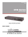
CPM Series
Control Port Manager
Models CPM-1600 and CPM-800
User's Guide
5 Sterling · Irvine · California 92618
(949) 586-9950 · Toll Free: 1-800-854-7226
Fax: (949) 583-9514 · http://www.wti.com
Table of Contents
1.
Introduction . . . . . . . . . . . . . . . . . . . . . . . . . . . . . . . . . . . . . . . . . . . . . 1-1
2.
Unit Description . . . . . . . . . . . . . . . . . . . . . . . . . . . . . . . . . . . . . . . . . . 2-1
2.1. Front Panel . . . . . . . . . . . . . . . . . . . . . . . . . . . . . . . . . . . . . . . . . . 2-1
2.2. Back Panel . . . . . . . . . . . . . . . . . . . . . . . . . . . . . . . . . . . . . . . . . . 2-2
3.
Getting Started . . . . . . . . . . . . . . .
3.1. Communication Parameters . . . . .
3.2. Connecting your PC to the CPM . .
3.3. Apply Power to the CPM . . . . . .
3.4. Communicating with the CPM Unit
.
.
.
.
.
.
.
.
.
.
.
.
.
.
.
.
.
.
.
.
.
.
.
.
.
.
.
.
.
.
.
.
.
.
.
.
.
.
.
.
.
.
.
.
.
.
.
.
.
.
.
.
.
.
.
.
.
.
.
.
.
.
.
.
.
.
.
.
.
.
.
.
.
.
.
.
.
.
.
.
.
.
.
.
.
.
.
.
.
.
.
.
.
.
.
.
.
.
.
.
.
.
.
.
.
3-1
3-1
3-1
3-2
3-3
4.
Hardware Installation . . . . . . . . . . . . . . . . . . .
4.1. Configure Setup Switches . . . . . . . . . . . . . .
4.1.1. Default Baud Rate (Sw1, Sw2, Sw3) . . .
4.1.2. Default Handshake (Sw4) . . . . . . . . .
4.1.3. Default Response Message Format (Sw5)
4.1.4. Default Command Echo (Sw7) . . . . . .
4.2. Connecting a Modem to the CPM . . . . . . . . .
4.3. Initialize the Unit to Default Settings . . . . . . .
4.4. Connecting Devices to the CPM . . . . . . . . . .
.
.
.
.
.
.
.
.
.
.
.
.
.
.
.
.
.
.
.
.
.
.
.
.
.
.
.
.
.
.
.
.
.
.
.
.
.
.
.
.
.
.
.
.
.
.
.
.
.
.
.
.
.
.
.
.
.
.
.
.
.
.
.
.
.
.
.
.
.
.
.
.
.
.
.
.
.
.
.
.
.
.
.
.
.
.
.
.
.
.
.
.
.
.
.
.
.
.
.
.
.
.
.
.
.
.
.
.
.
.
.
.
.
.
.
.
.
.
.
.
.
.
.
.
.
.
.
.
.
.
.
.
.
.
.
.
.
.
.
.
.
.
.
.
.
.
.
.
.
.
.
.
.
.
.
.
.
.
.
.
.
.
.
.
.
.
.
.
.
.
.
.
.
.
.
.
.
.
.
.
4-1
4-1
4-1
4-2
4-2
4-2
4-3
4-3
4-4
5.
Configuration . . . . . . . . . . . . . . . . . . .
5.1. Access to the CPM Command Mode . . .
5.2. Defining and Reading the Site I.D.. . . .
5.3. Port Configuration . . . . . . . . . . . . .
5.3.1. Configuration Conventions . . .
5.3.2. Port Modes. . . . . . . . . . . . .
5.3.2.1. The Any-To-Any Mode
5.3.2.2. The Modem Mode . . .
5.3.3. Command Availability . . . . . .
5.3.4. Port Configuration Commands .
.
.
.
.
.
.
.
.
.
.
.
.
.
.
.
.
.
.
.
.
.
.
.
.
.
.
.
.
.
.
.
.
.
.
.
.
.
.
.
.
.
.
.
.
.
.
.
.
.
.
.
.
.
.
.
.
.
.
.
.
.
.
.
.
.
.
.
.
.
.
.
.
.
.
.
.
.
.
.
.
.
.
.
.
.
.
.
.
.
.
.
.
.
.
.
.
.
.
.
.
.
.
.
.
.
.
.
.
.
.
.
.
.
.
.
.
.
.
.
.
.
.
.
.
.
.
.
.
.
.
.
.
.
.
.
.
.
.
.
.
.
.
.
.
.
.
.
.
.
.
.
.
.
.
.
.
.
.
.
.
.
.
.
.
.
.
.
.
.
.
.
.
.
.
.
.
.
.
.
.
.
.
.
.
.
.
.
.
.
.
.
.
.
.
.
.
.
.
.
.
5-1
5-1
5-2
5-2
5-2
5-3
5-3
5-3
5-4
5-4
6.
Operation . . . . . . . . . . . . . . . . . .
6.1. Port Connection and Disconnection
6.1.1. Using ASCII Commands to
6.1.2. Disconnecting Ports . . . .
6.2. Defining Hunt Groups . . . . . . . .
6.3. Port Buffers . . . . . . . . . . . . . .
. . . .
. . . .
Ports
. . . .
. . . .
. . . .
.
.
.
.
.
.
.
.
.
.
.
.
.
.
.
.
.
.
.
.
.
.
.
.
.
.
.
.
.
.
.
.
.
.
.
.
.
.
.
.
.
.
.
.
.
.
.
.
.
.
.
.
.
.
.
.
.
.
.
.
.
.
.
.
.
.
.
.
.
.
.
.
.
.
.
.
.
.
.
.
.
.
.
.
.
.
.
.
.
.
.
.
.
.
.
.
.
.
.
.
.
.
.
.
.
.
.
.
.
.
.
.
.
.
6-1
6-1
6-1
6-2
6-3
6-4
7.
Saving Configuration Parameters . . . . . . . . . . . . . . . . . . . . . . . . . . . . . . . . 7-1
7.1. Sending Parameters to a File . . . . . . . . . . . . . . . . . . . . . . . . . . . . . . . . 7-1
7.2. Restoring Saved Parameters. . . . . . . . . . . . . . . . . . . . . . . . . . . . . . . . . 7-2
8.
Command Reference Guide
8.1. Command Conventions
8.2. Command Response . .
8.3. Command Summary . .
8.4. Command Set . . . . . .
.
.
.
.
.
.
.
.
.
.
.
.
.
.
.
.
.
.
.
.
.
.
.
.
.
.
.
.
.
.
.
.
.
.
.
.
.
.
.
.
.
.
.
.
.
.
.
.
.
.
.
.
.
.
.
.
.
.
.
.
.
.
.
.
.
.
.
.
.
.
.
.
.
.
.
.
.
.
.
.
. . . . .
. . . . .
Connect
. . . . .
. . . . .
. . . . .
.
.
.
.
.
.
.
.
.
.
.
.
.
.
.
.
.
.
.
.
.
.
.
.
.
.
.
.
.
.
.
.
.
.
.
.
.
.
.
.
.
.
.
.
.
.
.
.
.
.
.
.
.
.
.
.
.
.
.
.
.
.
.
.
.
.
.
.
.
.
.
.
.
.
.
.
.
.
.
.
.
.
.
.
.
.
.
.
.
.
.
.
.
.
.
.
.
.
.
.
.
.
.
.
.
.
.
.
.
.
.
.
.
.
.
.
.
.
.
.
.
.
.
.
.
.
.
.
.
.
.
.
.
.
.
.
.
.
.
.
.
.
.
.
.
.
.
.
.
.
.
.
.
.
.
.
.
.
.
.
.
.
.
.
.
.
.
.
.
.
.
.
.
.
.
.
.
.
.
.
8-1
8-1
8-2
8-3
8-4
i
CPM Series - Control Port Managers, User's Guide
Table of Contents
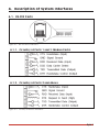
Appendices:
A.
Description of System Interfaces . . . . . . . . . . . .
A.1. RS-232 Ports. . . . . . . . . . . . . . . . . . . . . .
A.1.1. Circuitry at Ports 1 and 2 (Modem Ports)
A.1.2. Circuitry at Ports 3 and Above . . . . . .
A.2. Snap Adapters . . . . . . . . . . . . . . . . . . . . .
A.3. Cables . . . . . . . . . . . . . . . . . . . . . . . . .
B.
Specifications . . . . . . . . . . . . . . . . . . . . . . . . . . . . . . . . . . . . . . . . . . Apx-4
C.
FCC Notice . . . . . . . . . . . . . . . . . . . . . . . . . . . . . . . . . . . . . . . . . . . . Apx-5
D.
Customer Service . . . . . . . . . . . . . . . . . . . . . . . . . . . . . . . . . . . . . . . . Apx-5
.
.
.
.
.
.
.
.
.
.
.
.
.
.
.
.
.
.
.
.
.
.
.
.
.
.
.
.
.
.
.
.
.
.
.
.
.
.
.
.
.
.
.
.
.
.
.
.
.
.
.
.
.
.
.
.
.
.
.
.
.
.
.
.
.
.
.
.
.
.
.
.
.
.
.
.
.
.
.
.
.
.
.
.
.
.
.
.
.
.
.
.
.
.
.
.
.
.
.
.
.
.
.
.
.
.
.
.
Apx-1
Apx-1
Apx-1
Apx-1
Apx-2
Apx-3
List of Figures
2.1.
2.2.
3.1.
3.2.
5.1.
8.1.
A.1.
A.2.
A.3.
A.4.
A.5.
A.6.
Instrument Front Panel . . . . . . . . . . . . . . .
Instrument Back Panel (Model CPM-16 Shown)
The CPM Help Screen . . . . . . . . . . . . . . .
The Status Screen . . . . . . . . . . . . . . . . . .
Port Configuration Menu (Port 2 Shown) . . . .
The Status Screen . . . . . . . . . . . . . . . . . .
RS-232 Port Connectors . . . . . . . . . . . . . .
Circuitry at Ports 1 and 2 (Modem Ports) . . . .
Circuitry at Ports 3 and Above . . . . . . . . . . .
Snap Adapter Interface . . . . . . . . . . . . . . .
Snap Adapters . . . . . . . . . . . . . . . . . . . .
Straight Cables . . . . . . . . . . . . . . . . . . . .
.
.
.
.
.
.
.
.
.
.
.
.
.
.
.
.
.
.
.
.
.
.
.
.
.
.
.
.
.
.
.
.
.
.
.
.
.
.
.
.
.
.
.
.
.
.
.
.
.
.
.
.
.
.
.
.
.
.
.
.
.
.
.
.
.
.
.
.
.
.
.
.
.
.
.
.
.
.
.
.
.
.
.
.
.
.
.
.
.
.
.
.
.
.
.
.
.
.
.
.
.
.
.
.
.
.
.
.
.
.
.
.
.
.
.
.
.
.
.
.
.
.
.
.
.
.
.
.
.
.
.
.
.
.
.
.
.
.
.
.
.
.
.
.
.
.
.
.
.
.
.
.
.
.
.
.
.
.
.
.
.
.
.
.
.
.
.
.
.
.
.
.
.
.
.
.
.
.
.
.
.
.
.
.
.
.
.
.
.
.
.
.
.
.
.
.
.
.
.
.
.
.
.
.
.
.
.
.
.
.
.
.
.
.
.
.
.
.
.
.
.
.
.
.
.
.
.
.
.
.
.
.
.
.
.
.
.
.
.
.
.
.
.
.
.
.
.
.
.
.
.
.
. . 2-1
. . 2-2
. . 3-3
. . 3-4
. . 5-5
. . 8-5
Apx-1
Apx-1
Apx-1
Apx-2
Apx-2
Apx-3
ii
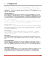
1.
Introduction
WTI's CPM-1600 and CPM-800 Control Port Managers provide a cost effective means for
control and management of network hardware without SNMP in-band restrictions. Both
models allow on-site or remote communication with any piece of equipment with an RS-232
command port. Devices can be accessed without the need to travel to the installation site, even
when your network is down.
Versatile Connectivity
The CPM provides a practical solution for applications that require communication between
devices operating at dissimilar baud rates. Up to 16 different devices can be connected to the
CPM without the need to select a common baud rate. Each port can be individually configured
for specific baud rates, parity, handshaking format, and various other parameters and options.
Easy Set-Up and Operation
Configuration of the CPM is simple. A convenient menuing system is used to select
communications parameters, and enable or disable options. The CPM can be easily configured
to fit the requirements of almost any data communications application.
Limited Command Access
The CPM is ideal for situations that require limited access to important commands. Each port
can be individually configured to allow access to all commands (Administrator), or only allow
access to basic commands (User).
Modular Design
RJ11 jacks and RS-232 Modular Adapters allow for quick, easy connection to computers,
modems, and other LAN hardware. The CPM is compact and takes only one rack unit (1.75
inches) of vertical rack space.
Buffered Ports
The CPM has 256KB or 512KB of non-volatile, dynamically allocated buffer memory. This
prevents data overflow during communication between two ports operating at dissimilar baud
rates.
Modem Communication
The CPM can either be controlled by a local PC that communicates with the unit via cable, or
controlled via modem by a remote PC. ProComm® (or another communications program) is
used to send commands to connect ports or display status. All devices connected to the CPM
have access to the modem. Modem ports are password protected to restrict unauthorized access
to connected devices.
Configuration Backup
Once you have configured the CPM to fit the requirements of your application, parameters and
options can be sent to an ASCII text file and saved for future retrieval. If configuration is
accidentally altered or deleted, parameters can be reloaded using your terminal emulation
software.
1-1
CPM Series - Control Port Managers, User's Guide
Introduction
CPM-1600 and CPM-800
This User's Guide discusses both the CPM-1600 and CPM-800 Control Port Managers. The
CPM-1600 includes 16 ports, and the CPM-800 includes eight ports. All other features
function identically.
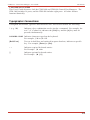
Typographic Conventions
Throughout this manual, typefaces and characters have been used to denote the following:
^ (e.g. ^E)
Indicates a key combination used to invoke a command. For example, the
text "^A" (Control A) indicates the [Ctrl] key and the [A] key must be
pressed simultaneously.
COURIER FONT Indicates characters typed on the keyboard.
For example, /^E or /P 02.
[Bold Font]
Text set in bold face and enclosed in square brackets, indicates a specific
key. For example, [Enter] or [Esc].
<>
Indicates required keyboard entries:
For Example: /P <n>
[]
Indicates optional keyboard entries.
For Example: /W [n]
1-2
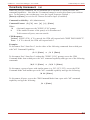
2.
Unit Description
2.1. Front Panel
Figure 2.1: Instrument Front Panel
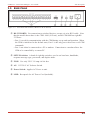
¬ CLEAR: Used to restart the CPM operating program without changing user-selected
parameter settings or breaking port connections.
ON: Lights when AC Power is applied to the unit.
® SET: Used to initialize the CPM to the defaults specified by Setup Switch configuration.
To initialize the CPM, press and hold both the SET button and the CLEAR button, release
only the CLEAR button, and then release the
SET button.
Note: When the CPM is initialized, all command-selected parameters will be
cleared, and the CPM will revert to the default parameters specified by the current
Set-Up Switch configuration.
¯ RDY: Flashes to indicate the unit is operational.
° ACTIVITY: The Activity LEDs light to indicate that a corresponding port is receiving
data. Note that the model shown here is the CPM-1600 (16 ports), model CPM-800 has
eight Activity indicators.
2-1
CPM Series - Control Port Managers, User's Guide
Unit Description
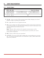
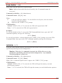
2.2. Back Panel
Figure 2.2: Instrument Back Panel (Model CPM-16 Shown)
¬ RS-232 PORTS: For connection to switched devices, accepts six wire RJ11 cable. Note
that the model shown here is the CPM- 1600 (16 Ports), model CPM-800 has eight RS232 Ports.
• Port 1 is used for communication with the CPM during set-up and configuration. When
the CPM is initialized to the default state, Port 1 is the only port with access to all CPM
commands.
• Port 1 can either be connected to a PC or modem. Connection to a modem allows the
CPM to be controlled by a remote PC.
SETUP Switches: A bank of eight dip switches, used to set baud rate, handshake,
response message type, port mode, and duplex mode.
® FUSE: Use only 250 V 1/8 amp slo blo fuse
¯ AC: 115/220 V AC Selector Switch
° Power Switch: Applies AC Power to unit.
± LINE: Receptacle for AC Power Cord (included).
2-2
3.
Getting Started
This section provides a brief overview of the CPM's basic capabilities, and describes tests that
can be performed to determine if the unit is operating properly.
3.1. Communication Parameters
The Setup Switches, located on the CPM Back Panel, are used to select default settings for all
CPM RS-232 ports. A label located adjacent to the Setup Switches summarizes switch
functions.
When the CPM is shipped from the factory, the Setup Switches are configured for 9600 baud, 8
Bits-No Parity, DTR handshaking, verbose command response, and no echo (all switches
down).
For the purpose of this overview, use the default Setup Switch configuration. Set your
communications program (e.g. ProComm) to use the following parameters:
· 9600 Baud
· 8 Bits, No Parity
· DTR Handshaking
· Full Duplex
Using Other Parameters (Optional): If desired, the CPM can be set to match the parameters
used by the communications program. Refer to the label on the bottom of the CPM, and
configure Setup Switches accordingly. After changing the Set-Up Switches, initialize the
CPM; press and hold the SET and CLEAR keys, release CLEAR, and then release SET.
Note:
• Section 4.1 describes procedures for setting the CPM to match the parameters
used by your communications program.
• If Setup Switches are changed, the new configuration will not take effect until the
CPM is initialized.
3.2. Connecting your PC to the CPM
In order to set-up the unit, a PC must be connected to Port 1. Port 1 is always used for
communication during set-up. This is because Port 1 is the only CPM port that will allow
access to all commands when the unit has been initialized to the default state.
Note that after the unit has been installed and configured, other CPM ports can also be granted
access to all CPM commands. This allows any CPM port to function as a "Control Port" after
configuration is complete.
3-1
CPM Series - Control Port Managers, User's Guide
Getting Started
The CPM can either be controlled by a local PC that communicates via cable, or controlled by
a remote PC that communicates via modem. For the purpose of this overview, a local PC
running ProComm (or a similar communications program), will be cable connected to CPM
Port 1.
Note: Communication via Modem (Optional): If desired, this overview can also
be performed via modem.
Perform the following procedure to connect a PC to Port 1.
1. Attach an appropriate Snap Adapter to your PC COM port. Make certain to connect to
the PC COM port used by your communications program.
a) For 25 pin PC COM ports, use the SA-12F Snap Adapter supplied with the CPM.
b) For nine pin PC COM ports, use the SA-9F Snap Adapter supplied with the CPM.
c) For a description of the Snap Adapter interface, please refer to Appendix A.
2. Attach one end of the RJ11 cable (included with the CPM) to Port 1. Attach the other end
of the cable to the Snap Adapter installed in your PC COM port. Note that the cable used
for connection must be a six wire, straight wired RJ11 cable.
3.3. Apply Power to the CPM
Connect the power cable to the CPM and plug the cable into an AC power source. Press the
Power Switch to ON. The ON LED should light, and the RDY LED should begin to flash.
Note: If all Port Activity LEDs flash upon power-up, this may indicate a problem
with the CPM unit. Please contact WTI Technical Support as described in
Appendix D.
3-2
CPM Series - Control Port Managers, User's Guide
Getting Started
3.4. Communicating with the CPM Unit
Perform the following procedure to enter the CPM Command Mode, explore the unit's basic
features, and check for proper operation.
1. If you have not already done so, start your communications program (e.g. ProComm).
2. Issue the "Wake Port" command to access the CPM Command Mode and make certain the
port is ready to receive commands. Type /, then simultaneously press the [Ctrl] key and
the [E] key, and then press [Enter] (/^E [Enter]). The "CPM>" prompt should appear.
a) If the "CPM>" prompt is displayed, you have successfully accessed the Command
Mode. This indicates the PC has contacted the CPM, and the unit is operating
properly.
b) If the "CPM>" prompt is not displayed, this may indicate a problem in communicating
with the CPM unit. Check the following:
n
Cable Connection: Check the cable connection between the CPM unit and the PC.
Make certain the Snap Adapter and RJ11 cable connectors are firmly seated.
n
Communication Parameters: Make certain the CPM and ProComm are using the
same communication parameters.
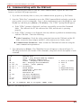
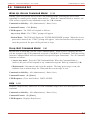
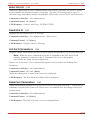
3. Type /H and press [Enter]. The CPM Help Screen will appear as shown in Figure 3.1.
The Help Screen lists all available CPM commands, along with a brief description of each
command.
/^E
/X
/H
/S
/W [n]
/C <n> [n]
/D <n> |...| *
/E <n> | *
/I
/F
/J
/P <n>
/U
/L-[n]
/G-00
Wake-Up Port
Sleep - Only Accepts Wake-Up Command
Help - Displays Command List
Status - Displays Status Screen
Who - Displays Port Parameters
Connect - Local [Remote]
Disconnect
Erase Buffer
Initialize / Test Unit
Enter Site ID
Read Site ID
Set Port Parameters
Read Port Parameters
Load Port Parameters
Reset All Ports
n
N
|
*
<>
[]
Port # or Name
Port #
"or"
"all"
Required Entry
Optional Entry
/D, /E, /I Commands: Add /Y to bypass "SURE? (Y/N)"
Figure 3.1: The CPM Help Screen
3-3
CPM Series - Control Port Managers, User's Guide
SYSTEM STATUS
Getting Started
VERSION 1.4
MEMORY 512KB
PORT |
NAME
| STATUS | BAUD | B/P | HS | MODE | TIMEOUT | BUFF | CTS
------+----------+--------+------+-----+------+--------+---------+------+---01 |
|*FREE
| 9600 | 8N | DTR | ANY
|
OFF
| ---- | H
02 |
| FREE
| 9600 | 8N | DTR | ANY
|
OFF
| ---- | L
03 |
| FREE
| 9600 | 8N | DTR | ANY
|
OFF
| ---- | L
04 |
| FREE
| 9600 | 8N | DTR | ANY
|
OFF
| ---- | L
05 |
| FREE
| 9600 | 8N | DTR | ANY
|
OFF
| ---- | L
06 |
| FREE
| 9600 | 8N | DTR | ANY
|
OFF
| ---- | L
07 |
| FREE
| 9600 | 8N | DTR | ANY
|
OFF
| ---- | L
08 |
| FREE
| 9600 | 8N | DTR | ANY
|
OFF
| ---- | L
|
|
|
|
|
|
|
|
|
09 |
| FREE
| 9600 | 8N | DTR | ANY
|
OFF
| ---- | L
10 |
| FREE
| 9600 | 8N | DTR | ANY
|
OFF
| ---- | L
11 |
| FREE
| 9600 | 8N | DTR | ANY
|
OFF
| ---- | L
12 |
| FREE
| 9600 | 8N | DTR | ANY
|
OFF
| ---- | L
13 |
| FREE
| 9600 | 8N | DTR | ANY
|
OFF
| ---- | L
14 |
| FREE
| 9600 | 8N | DTR | ANY
|
OFF
| ---- | L
15 |
| FREE
| 9600 | 8N | DTR | ANY
|
OFF
| ---- | L
16 |
| FREE
| 9600 | 8N | DTR | ANY
|
OFF
| ---- | L
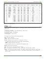
Figure 3.2: The Status Screen
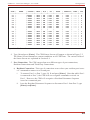
4. Type /S and press [Enter]. The CPM Status Screen will appear as shown in Figure 3.2.
The Status Screen summarizes current conditions at all CPM Ports. The various fields of
the Status Screen are explained in Section 8.4.
5. Port Connection: The CPM can perform two different types of port connections;
Resident Connections and Third Party Connections.
a) Resident Connection: This type of connection occurs when your resident port issues
a /C command to connect to a second port.
i.
To connect Port 1 to Port 3, type /C 3 and press [Enter]. Note that while Port 1
is connected to Port 3, the CPM will not recognize commands received via
Port 1. However, the CPM will recognize a Resident Disconnect Sequence
issued at a connected port.
ii.
Issue the Resident Disconnect Sequence to disconnect Port 1 from Port 3; type
[Enter]+++[Enter].
3-4
CPM Series - Control Port Managers, User's Guide
Getting Started
b) Third Party Connection: This type of connection occurs when your resident port
issues a command to create a connection between two other ports.
i.
To connect Port 3 to Port 4, type /C 3 4 and press [Enter].
ii.
Note that while Ports 3 and 4 are connected, Port 1 will still recognize CPM
commands. Type /S and press [Enter], the Status Screen will appear. Note that
the "STATUS" column now lists Ports 3 and 4 as connected, while Port 1 is listed
as "FREE".
iii. Issue a Third Party Disconnect command to disconnect Ports 3 and 4. Type
/D 3 and press [Enter].
iv.
Type /S and press [Enter] to re-display the Status Screen. Note that the
"STATUS" column now lists Ports 3 and 4 as "FREE".
6. Define the Site I.D. message. The Site I.D. allows the user to denote the location or
name of the CPM unit. The Site I.D. cannot include non-printable ASCII codes such as
NULLS and Line Feeds.
a) Type /F and press [Enter]. The CPM will prompt the user to enter the Site I.D.. Key
in the desired Site I.D. and press [Enter]. Up to 32 characters long.
b) To display the Site I.D., type /J and press [Enter].
c) Note that the Site I.D. will be cleared when the CPM is initialized.
This completes the introductory overview of the CPM unit. After you have determined that the
unit is operating properly, configure the CPM as described in Section 4.
3-5
4.
Hardware Installation
This section describes the procedures for installing the CPM and connecting devices to the
unit.
4.1. Configure Setup Switches
When the CPM is shipped from the factory, the Setup Switches are configured for 9600 baud, 8
Bits-No Parity, DTR handshaking, verbose command response, and no echo (all switches
down). These switch settings are compatible with most applications. If the default settings are
not compatible with your application, change the switch settings as described in the following
subsections.
Setup Switches should be configured to match the communication parameters used by the
device attached to Port 1. This allows access to the CPM if the unit is initialized to default
parameters.
Note: Communication parameters (baud rate, parity, and etc.) can also be
individually selected for each CPM port by accessing the Command Mode and
invoking the /P command as described in Section 5.3.4. However, when the CPM is
initialized, parameters will return to the settings specified by the current Set-Up
Switch configuration.
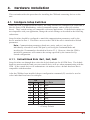
4.1.1. Default Baud Rate (Sw1, Sw2, Sw3)
Setup Switches one through three select the default baud rate for all CPM Ports. The default
baud rate must match the baud rate your control device will use when communicating with the
CPM. If the control device will communicate via modem, select a default baud rate that is
compatible with the modem.
After the CPM has been installed, the port configuration command (/P) can also be used to
select individual baud rates for each port.
SW
1
2
3
Baud Rate
D
U
D
U
D
U
D
U
D
D
U
U
D
D
U
U
D
D
D
D
U
U
U
U
9600*
300
1200
2400
4800
9600
19.2K
38.4K
* = Factory Default
4-1
CPM Series - Control Port Managers, User's Guide
Hardware Installation
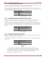
4.1.2. Default Handshake (Sw4)
The default handshake format should be set to match the device attached to CPM Port 1. Setup
Switch 4 can select either DTR (hardware) or XON/XOFF handshaking.
After the CPM has been installed, the port configuration command (/P) can also be used to
select both DTR and XON/XOFF handshaking, or no handshaking. The /P command can select
a different handshaking format for each port.
Switch 4
Down
Up
Handshake
DTR *
XON/XOFF
* = Factory Default
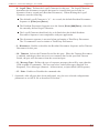
4.1.3. Default Response Message Format (Sw5)
The CPM can respond with either verbose (English text) or terse (numeric / abbreviated )
messages. Both terse and verbose response messages are summarized in Section 8.2.
After the unit has been installed, the /P command can also set the response message format to
"none" (Quiet Mode). When the Quiet Mode is selected, the CPM will not send messages in
response to commands. The /P command can select a different Response Message Format for
each port.
Switch 5
Down
Up
Response Message Type
Verbose (English Text) *
Terse (abbreviated / numeric)
* = Factory Default
4.1.4. Default Command Echo (Sw7)
Switch Seven enables or disables the Command Echo. When enabled, characters sent to the
CPM will be echoed back to the control device.
After the CPM is installed, the /P command can individually select the Command Echo Mode
for each port.
Switch 7
Down
Up
Command Echo
Disable*
Enable
* = Factory Default
Note:
• If the Setup Switch configuration is changed while the unit is powered on, the
new configuration will not take effect until the CPM is initialized. The CPM can
be initialized by invoking the /I command, or by pressing and holding the CLEAR
and SET keys, releasing the CLEAR key, and then releasing the SET key.
• Setup Switches 6 and 8 are not used.
4-2
CPM Series - Control Port Managers, User's Guide
Hardware Installation
4.2. Connecting a Modem to the CPM
The CPM can either be controlled by a local PC that communicates with the unit via cable, or
controlled by a remote PC that communicates via modem.
The CPM's Modem Mode provides several useful options that can be employed when the unit is
controlled via modem. The Modem Mode, which is only available on CPM Ports 1 and 2,
provides password protected access to the Command Mode, and allows the user to re-define the
Modem Reset Message and Hang-Up Message.
Note:
• An external modem can also be connected to any other CPM port, providing the
modem does not require password protection, or an externally generated reset
message or hang-up message.
• The Modem Mode can also provide password protected access to the Command
Mode when the CPM is controlled by a local device that communicates with the
unit via cable.
Regardless of whether the unit will be controlled via cable or modem, the Control Device
should communicate with the CPM via Port 1. This allows access to the unit if the CPM is
initialized to default parameters. In the default state, Port 1 is the only port with access to all
CPM commands. After the CPM has been installed and configured, Port 2 can also be
connected to a modem to allow remote access to the Command Mode.
To connect a modem to the CPM, proceed as follows:
1. Install the SA-25M Snap Adapter (included with the unit) in the modem's serial port.
2. Connect a six wire, straight wired RJ11 cable from the Snap Adapter to CPM Port 1.
Refer to Appendix A for information on Snap Adapters and straight wired cables.
4.3. Initialize the Unit to Default Settings
If Setup Switch configuration has been changed while the CPM is powered on, the unit must be
initialized in order for the new switch configuration to take effect.
Caution: When the CPM is initialized, the unit will revert to the parameters
specified by the current Set-Up Switch configuration. Any command-selected
parameters will be lost.
1. Simultaneously press the SET button and CLEAR button, located on the face of the CPM
unit.
2. Release the CLEAR button, wait one second, and then release the SET button.
4-3
CPM Series - Control Port Managers, User's Guide
Hardware Installation
4.4. Connecting Devices to the CPM
From modems to printers, many different types of devices can be connected to the CPM. To
physically connect a device to the CPM, proceed as follows.
1. Access the Command Mode.
2. Determine which CPM port will be used for connection to the new device (e.g. Port 3).
3. Type /S and press [Enter]. The CPM will display the Status Screen. Find the "BUFF"
column in the Status Screen. The BUFF column lists the amount of memory currently
being used to store buffered data for each port.
a) If the Status Screen indicates the port has data stored in buffered memory, issue the /E
command to clear the buffer. The /E command uses the following format:
/E nn [Enter]
Where nn is the number of the CPM port buffer to be cleared. For example, to clear
the buffer for port three, type /E 3 and press [Enter].
b) Note that buffered data which has been cleared using the /E command cannot be
recovered.
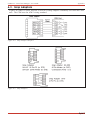
4. Attach an appropriate Snap Adapter to an RS-232 serial port on the device you intend to
connect. Refer to Appendix A for more information on WTI Snap Adapters.
a) Modem: Ports 1 and 2 can be configured for the Modem Mode, which provides
Password restricted access to the Command Mode, and allows the user to re-define
the Modem Reset and Hang-Up Messages. An external modem can also be connected
to any other CPM port, providing the modem does not require password protection, or
an externally generated reset or hang up message. Connect an SA-25M Snap Adapter
to the modem's serial port.
b) PC: Any CPM RS-232 Port can be used for connection to a PC. For 25 pin PC COM
ports, use an SA-12F Snap Adapter. For 9 pin PC COM ports, use an SA-9F Snap
Adapter.
c) Printer: Any CPM RS-232 Port can be used for connection to a printer. Use an SA12M Snap Adapter.
d) Other Devices: For a description of the CPM Port interface, please refer to
Appendix A.
5. Connect a 6 wire, straight wired RJ11 cable from the Snap Adapter to a vacant CPM RS232 port.
6. Select communication parameters for the port as described in Section 5.3.4.
4-4
5.
Configuration
This section describes procedures that are used to configure the CPM to fit the requirements of
your application.
5.1. Access to the CPM Command Mode
When the Command Mode is active, the user can invoke commands to configure the unit,
display status, and connect or disconnect ports. The Command Mode can be accessed from a
local PC that communicates with the CPM via cable, or accessed by a remote PC that
communicates via modem.
1. Start the communications program (e.g. Procomm) on your local or remote PC. Make
certain the CPM and ProComm are set for the same communication parameters (e.g. baud,
parity, etc.).
2. Access the CPM Command Mode.
a) Local Access: To access the command mode from a local PC, type /^E and press
[Enter]. The CPM Command Mode is now active.
b) Remote Access: To access the command mode from a remote PC, proceed as
follows:
i.
Dial the number for the modem connected to CPM Port 1. The CPM will
respond with the "ENTER PASSWORD" prompt.
ii.
If you have defined a password for modem access, key in your password and
press [Enter]. If the password has not been defined, just press [Enter]. The
"CPM>" prompt will appear.
iii. The Password prompt will not be displayed when the CPM is first configured, or
immediately after the unit has been initialized. In the default state, the port will
be set for the "Any-to-Any" Port Mode, and the Password feature will be
disabled.
iv.
Type /^E and press [Enter] to make certain the Command Mode is active, and
the unit is ready to receive commands.
5-1
CPM Series - Control Port Managers, User's Guide
Configuration
5.2. Defining and Reading the Site I.D.
When your application involves communication with several CPM units, the Site I.D. can
indicate the location or name of each unit. If you have already defined the Site I.D. in
Section 3, and have not reinitialized the CPM, skip this section.
Note:
• The Site I.D., cannot include non-printable ASCII Codes, such as NULLS and
Line Feeds.
• The Site I.D. will be cleared when the CPM is initialized to default settings.
1. Access the Command Mode.
2. Type /F and press [Enter]. The CPM will prompt the user to enter the Site I.D.. Key in
the desired Site I.D. and press [Enter]. Up to 32 characters long.
3. To display the Site I.D., type /J and press [Enter].
5.3. Port Configuration
5.3.1. Configuration Conventions
When responding to prompts, invoking commands, and selecting items from the port
configuration menu, note the following:
· To select an item from the Port Configuration menu, key in the number for the item and
press [Enter].
· When defining the Port Name or Password, do not use ASCII Control Codes, the slash
character (/), quotation marks ("), the asterisk character (*) or blank spaces.
· The Port Name cannot begin with a number.
· Refer to the instructions in each screen for additional functions available under that screen.
· To exit a menu or prompt without changing its current configuration, press [Esc].
· Note that the Password and Port Names are case sensitive. When defining the Passwords
or Port Names, take care to note the exact text, including the case of each character.
5-2
CPM Series - Control Port Managers, User's Guide
Configuration
5.3.2. Port Modes
The CPM offers two port operation modes; the Any-to-Any Mode and the Modem Mode.
5.3.2.1. The Any-To-Any Mode
When the Any-to-Any Mode is selected, the CPM will respond to ASCII commands to connect
that port to any other port. All CPM ports can be configured for the Any-to-Any Mode.
When a port is configured for the Any-to-Any Mode, a password will not be required in order
to access the Command Mode. In addition, the port will not send the defined Modem Reset
Message or Hang-Up Message.
5.3.2.2. The Modem Mode
The Modem Mode allows the port to be connected to an external modem. A port configured
for Modem Mode can also perform all of the functions normally available in the Any-to-Any
Mode. Only Ports 1 and 2 can be configured for the Modem Mode.
In addition to allowing data transfer, the Modem Mode also provides several functions
specifically related to modem communication. When the Modem Mode is selected, the user
can also define a password to restrict remote access to the Command Mode. When the CPM is
contacted via modem, the unit will prompt the caller to enter the password. The CPM allows
three attempts to enter the password. If the correct password is not entered in three attempts,
or if the user does not respond to the password prompt within 30 seconds, the CPM will
disconnect and reset the modem.
The Modem Mode also allows redefinition of the Modem Reset Message and Hang-Up
Message. Although the default reset and hang-up messages are compatible with most modems,
these messages can be re-defined when necessary.
Note that a modem can also be connected to a CPM port configured for the Any-to-Any Mode,
providing the modem does not require an externally supplied reset message or hang-up
message.
When using the Modem Mode, note the following:
· The SA-25 Snap Adapter allows correct transfer of DCD and handshaking signals. When
using the SA-25, the DSR signal from the modem must be high in order to pull up the DTR
signal.
· When a modem is connected to the CPM, other connected devices can use the modem for
calling out. To call out from the modem, invoke the /C command to connect to the port,
and access the modem as you normally would.
5-3
CPM Series - Control Port Managers, User's Guide
Configuration
5.3.3. Command Availability
The "Commands" field in the Port Configuration menu allows the user to specify which CPM
commands will be available to each port. The user can either select "All" commands or only
"Basic" commands. The "All" option is normally selected for administrator ports, and allows
access to all CPM commands. The "Basic" option is normally selected for user ports, and
allows limited access to CPM commands. Section 8.3 summarizes "All" and "Basic"
commands.
In the default state, Port 1 is the only port with access to "All" CPM commands. When ports
are configured, at least one CPM port should be granted access to "All" CPM commands.
5.3.4. Port Configuration Commands
The following section describes the procedure for using the Port Configuration Menu to select
options for each port.
Note that parameters and options selected via the Port Configuration Menu will stay in effect
until the CPM is initialized using the /I command or the CLEAR and SET buttons. When the
unit is initialized, parameters will revert to the defaults specified by the Setup Switch
configuration.
After parameters have been selected, the configuration can be saved to an ASCII file on your
PC. Later, if the CPM configuration is altered or deleted, the file with the saved parameters
can be sent to the CPM to automatically reconfigure the unit without the need to manually redefine each parameter. Section 7 provides a description of the procedure for saving
configuration parameters to an ASCII file.
To select port parameters, proceed as follows:
1. Access the CPM Command Mode.
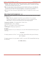
2. Type /P, followed by the number of the port to be configured, and press [Enter]. For
example, to configure Port 2, type /P 02 [Enter]. The Port Configuration menu will
appear as shown in Figure 5.1.
The Port Configuration menu offers the following options:
• 1. Port Name: Allows the user to assign a name to this port. For example,
"MODEM". Up to eight characters.
• 2. Baud Rate: Defines the baud rate for this port. The Baud rate can be set to any
standard rate from 300 to 38.4K bps.
• 3. Bits/Parity: Defines the data bits and parity for this port.
• 4. Stop Bits: Defines the stop bits for this port.
• 5. Handshake: Defines the handshake format for this port. The handshake can be set
to XON/XOFF, DTR (hardware), Both, or None.
5-4
CPM Series - Control Port Managers, User's Guide
Configuration
PORT PARAMETERS #02
1.
2.
3.
4.
5.
6.
7.
8.
9.
PORT NAME:
BAUD RATE:
BITS/PARITY:
STOP BITS:
HANDSHAKE:
MODE:
COMMANDS:
LOGOFF CHAR:
DISCONNECT
SEQ:
TIMEOUT:
10. TIMEOUT:
11. MESSAGE TYPE:
12. ECHO:
9600
8-None
1
DTR
Any-to-Any
All
+
On
Off
5 Sec
Verbose
On
Enter: "<" previous port,
">" next port,
"##" change parameter
<ESC> exit ...
Figure 5.1: Port Configuration Menu (Port 2 Shown)
• 6. Mode: Defines the operation mode for this port. For Ports 1 and 2, the user can
select either "Any-to-Any" mode or Modem Mode. For Ports 3 and above, only the
Any-to-Any mode can be selected.
When the Modem Mode is selected for Ports 1 or 2, the CPM will display an additional
menu that is used to select the following parameters:
n
1. Password: Defines a Password to restrict modem access to the Command Mode.
To disable the password requirement, press [Enter] without keying in a password.
The Password is case sensitive, and can be up to 32 characters long.
n
2. Reset Message: When necessary, this option can be used to re-define the
modem reset message. The default Reset Message is ATQ0&C1&D0S0=1. This
reset message is compatible with most modems.
n
3. Hang-Up Message: When necessary, this option can be used to re-define the
modem hang-up message. The default Hang-Up Message is ~~~+++~~~ATH0.
This Hang-Up Message is compatible with most modems.
• 7. Commands: Determines which commands will be available to this port. The port
can be configured to recognize only Basic commands (user), or All commands
(administrator). When the CPM is configured, at least one port (typically Port 1)
should be granted access to All CPM commands.
5-5
CPM Series - Control Port Managers, User's Guide
Configuration
• 8. Logoff Char.: Defines the Logoff Character for this port. The Logoff Character
determines the disconnect sequence that must be issued at this port in order to
disconnect from a second port (Resident Disconnect). When defining the Logoff
Character, note the following:
n
The default Logoff Character is "+". As a result, the default Resident Disconnect
Sequence is [Enter]+++[Enter].
n
The Resident Disconnect Sequence uses the format [Enter]###[Enter], where # is
the currently defined Logoff Character.
n
The Logoff Character should only be re-defined when the default Resident
Disconnect Sequence is not compatible with your application.
n
The disconnect sequence is not used when performing a Third Party Disconnect.
The /D command is used to initiate a Third Party Disconnect.
• 9. Disconnect: Enables or disables the Resident Disconnect Sequence and/or Timeout
Disconnect for this port.
• 10. Timeout: Selects the Timeout Period for this port. When the Timeout Disconnect
is enabled, and the port does not receive or transmit data for the specified Timeout
Period, the port will disconnect from the associated port.
• 11. Message Type: Defines the type of response messages that will be sent when the
CPM responds to commands. The user can select Verbose Messages (English Text
Response), Terse Messages (Numeric / Abbreviation), or Quiet Mode (No Response).
• 12. Echo: Enables or Disables the command echo.
3. (Optional) After all ports have been configured, save the user-selected configurations
parameters to an ASCII file as described in Section 7.
5-6
6.
Operation
6.1. Port Connection and Disconnection
This section describes the procedure for using ASCII commands to make and break connections
between CPM ports.
The CPM allows communication between devices without the requirement that both devices
use the same communication parameters. This allows the user to connect devices that use
dissimilar baud rates, parity, handshake, and etc.. The CPM converts data rates and other
communications parameters, eliminating the need to select common parameters for all
connected devices.
6.1.1. Using ASCII Commands to Connect Ports
Two different types of connections can be made between CPM ports; Resident Connections and
Third Party Connections.
In a Resident Connect, your resident port issues a /C command to connect to a second port.
For example, if Port 4 issues the /C command to connect to Port 5, this is a Resident Connect.
In a Third Party Connect, your resident port issues a /C command to create a connection
between two other ports. For example, if Port 1 is your resident port, and Port 1 issues a
command to connect Port 2 to Port 3, this is a Third Party Connect.
Note:
• Port Names are case sensitive. When invoking the /C command, make certain to
note the case of each letter of the Port Name.
• Ports that have been granted Basic (User) command capability, can only use the /C
command to perform a Resident Connect. Ports with Basic command capability
cannot initiate a Third Party Connect.
To Connect CPM ports, proceed as follows:
1. Access the CPM Command Mode.
2. Invoke the /C command to connect the desired ports.
a) Resident Connect: To connect your resident port to another port, type /C nn and
press [Enter]. Where nn is the number or name of the port you want to connect.
Examples:
n To connect your resident port to Port 8, type /C 08 [Enter].
n
To connect your resident port to a port named "MODEM", type /C MODEM
[Enter].
6-1
CPM Series - Control Port Managers, User's Guide
Operation
b) Third Party Connect: To connect any two ports (other than your resident port), type
/C nn NN and press [Enter]. Where nn and NN are two CPM port numbers or port
names.
Examples:
n To connect Port 5 and Port 6, from a third port with "All" command capability, type
/C 05 06 [Enter].
n
To connect a Port named "SALES" to a Port named "MODEM", from a third port
with "All" command capability, type /C SALES MODEM [Enter].
When the /C command specifies the port name, it is only necessary to enter enough letters to
differentiate the desired port from other ports. For example, to connect your resident port to a
port named "SALES", the connect command can be invoked as /C S, providing no other port
names begin with the letter "S".
6.1.2. Disconnecting Ports
There are three different methods for disconnecting ports, the Resident Disconnect, the Third
Party Disconnect, and the No Activity Timeout. Providing the timeout feature has been
enabled, a No Activity Timeout can be used to disconnect resident ports or third party ports.
Note:
• Port Names are case sensitive. When invoking the /D command, make certain to
note the case of each letter of the Port Name.
• In the DTR mode, the DTR signal will drop for approximately 250 ms after a
disconnect has occurred.
1. Resident Disconnect: A Resident Disconnect disconnects your resident port from
another port. For example, if you are communicating via Port 3, and Port 3 is connected
to Port 4, a Resident Disconnect would be used to disassociate the two ports. A Resident
Disconnect is initiated by invoking the Logoff Sequence.
a) The default Logoff Sequence is [Enter]+++[Enter].
b) If the default Logoff Sequence is not compatible with your application, the Logoff
Character can be redefined using the /P (Port Configuration) command. For example,
if the Logoff Character is re-defined as @, the new Logoff Sequence will be
[Enter]@@@[Enter].
6-2
CPM Series - Control Port Managers, User's Guide
Operation
2. Third Party Disconnect: A Third Party Disconnect is used to disconnect two ports by
invoking the /D command at a third port. For example, if you are communicating via
Port 1, and you wish to disconnect Port 3 from Port 4, a Third Party Disconnect would be
used.
a) The /D (Disconnect) command can be invoked by any port that has been granted
access to "All" commands (Administrator).
b) The /D command line can specify both connected ports, or either of the two connected
ports. For example, if Port 3 is connected to Port 4, and Port 1 has access to "All"
commands, the user can invoke one of the following commands at Port 1:
/D 03 04 [Enter]
or
/D 03 [Enter]
or
/D 04 [Enter]
3. No Activity Timeout: Providing the Timeout Disconnect feature has been enabled for
either connected port, the No Activity Timeout can be used to disconnect Resident Ports,
or Third Party Ports.
a) The Timeout Feature is enabled and defined by invoking the /P command to access
the Port Configuration Menu for the desired port. Option 9 is used to enable or
disable the Timeout Feature, and Option 10 is used to define the Timeout Period.
b) When the Timeout Feature has been enabled, the port will automatically disconnect
when no additional data is received for the defined Timeout Period. The default
Timeout Period is 5 seconds.
6.2. Defining Hunt Groups
A Hunt Group creates a situation where the CPM will scan a group of user-specified ports, and
connect to the first available port in the group. Hunt Groups are created by assigning identical
or similar port names to two or more ports. Hunt groups can be defined using Any-to-Any
Mode Ports or Modem Mode Ports.
Note: Port Names are case sensitive. When invoking the /C command, make
certain to note the case of each letter of the Port Name.
1. Access the CPM Command Mode.
2. Invoke the /P command to access the Port Configuration Menu for the desired Port(s).
For example, to configure Port 4, type /P 4 [Enter].
3. From the Port Configuration Menu, select item 1. to define the Port Name.
4. Repeat steps 2 and 3 above to assign similar or identical names to the other port(s) you
wish to include in the Hunt Group. For example, a series of ports in a Hunt Group could
be named "PRINTER1", "PRINTER2", "PRINTER3", and etc., or all ports in the group
could be assigned the same name (e.g. "PRINTER").
6-3
CPM Series - Control Port Managers, User's Guide
Operation
5. To connect to the next available port in the hunt group, invoke the /C (Connect) command
using the port name to specify the desired group of ports. For example, /C PRINTER
[Enter].
6. The CPM will connect to the first available port in the Hunt Group. If all ports in the
specified Hunt Group are presently connected, the CPM will respond with the "BUSY"
message.
Note that it is only necessary to enter enough letters of the port name to differentiate the ports
in the Hunt Group from other ports. For example, to connect your resident port to the first
available port in a group of ports named "SALES1", "SALES2", "SALES3", and etc., the
connect command can be invoked as /C S, providing no other port names begin with the
letter "S".
The names of ports in Hunt Groups must be unique. Otherwise ports with names that are
similar or identical to the Hunt Group, will also be included in the Hunt Group.
Hunt Group Example 1:
1. Assume CPM Ports 1 and 2 have been configured in the Modem Mode, and modems have
been installed at both ports.
2. Assume Port 1 has been named "MODEM1" and Port 2 has been named "MODEM2".
3. If your resident port is Port 4, and you want to connect to the first available Modem,
access the CPM Command Mode, type /C MODEM and press [Enter].
Hunt Group Example 2:
1. Assume Ports 3, 4, and 5 have been configured in the Any-to-Any Mode and printers are
attached to each port.
2. All three ports have been named "PRINTER".
3. If your resident port is Port 1, and you want to connect Port 2 to the first available
printer, access the CPM Command Mode, type /C 02 PRINTER and press [Enter].
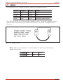
6.3. Port Buffers
When two ports are communicating at dissimilar baud rates, the Port Buffers prevent data
overflow at the slower of the two ports.
The Port Buffer provides 256K or 512K (optional) of non-volatile memory that is shared for
buffering purposes by all CPM ports. Buffer memory is dynamically allocated in blocks of 2K
characters. The Status Screen lists the amount of Buffer Memory currently used by each port.
Note that if data is allowed to accumulate in a port buffer, this will decrease the amount of
buffer memory available to other ports. If the Status Screen indicates an accumulation of data
at an unused port, the /E (Erase Buffer) command can be invoked to clear the buffer. To clear a
buffer, type /E nn [Enter], where nn is the number of the port buffer to be cleared.
6-4
7.
Saving Configuration Parameters
After you have configured the CPM to fit the requirements of your application, configuration
parameters can be downloaded to your PC and saved as an ASCII text file. Later, if the
configuration is accidentally altered, the file with the saved parameters can be uploaded to
automatically reconfigure the CPM without the need to manually define each parameter.
The saved parameters can also be uploaded to other CPM units. This allows rapid set-up when
several CPM units will be configured with the same parameters.
This section describes the procedure for using ProComm to save and load CPM parameters.
Note that this procedure can also be applied to other communications programs.
7.1. Sending Parameters to a File
1. Start Procomm and access the CPM Command Mode.
2. Use the /P command to disable the CPM's echo feature as described in Section 5.3.4.
When the Port Configuration menu is displayed, option 12 is used to enable or disable the
echo feature.
3. Press the [Page Down] key.
4. ProComm's Download Menu will appear. Select (A) ASCII. ProComm will display a
prompt which reads "ASCII DOWNLOAD - Please enter file name".
5. Type in a name for the file that will contain the saved CPM parameters using the full path
and drive designation. For example, "C:\CPM.PAR".
6. At the ProComm screen, type /U and press [Enter]. The CPM will send a series of
command lines to the file specified in Step 5 above. Each line describes parameters for
an individual Port.
a) The /U command must be invoked before ProComm's download timeout is reached.
The download timeout can be redefined using ProComm's set-up menu.
b) ProComm will emit a Beep when the download timeout period has elapsed.
7. When the CPM has finished sending parameters, press [Esc] to terminate ProComm's
Download mode.
7-1
CPM Series - Control Port Managers, User's Guide
Saving Configuration Parameters
7.2. Restoring Saved Parameters
This section describes the procedure for using ProComm to send stored parameters to the CPM
unit.
1. Start ProComm and access the CPM Command Mode. Press the [Page Up] key to
activate ProComm's Upload menu.
2. Select (A) ASCII. The system will display a prompt which reads "ASCII UPLOAD Please enter the file name".
3. Key in the name of the ASCII text file with the stored parameters using the full path and
drive designation and press [Enter]. For example, C:\CPM.PAR [Enter].
4. ProComm will send the ASCII text file to the CPM and saved parameters will be restored.
When ProComm has finished sending parameters to the CPM, press [Esc] to terminate
ProComm's Upload mode.
5. Type /S and press [Enter], the CPM's Status Screen will be displayed. Check the Status
Screen to make certain the CPM has been configured with the saved parameters.
7-2
8.
Command Reference Guide
This section describes the CPM's command set and explains options available to each
command.
8.1. Command Conventions
The commands described in this section conform to the following conventions:
· Slash Character: Almost all commands begin with the Slash Character (/). The only
exception is Resident Disconnect Sequence (Default = [Enter]+++[Enter]).
· Asterisk Character: When the asterisk character is entered as the argument of the /D
command (Disconnect Port), or the /E command (Erase Buffer) the command will be
applied to all ports. For example, to disconnect all ports, type /D * [Enter].
· Suppress "SURE (Y/N)?" Prompt: When the /D (Disconnect Port), /E (Erase Buffer),
or /I (Initialize Unit) commands are invoked, the /Y option can be included in the
command line to override the "SURE (Y/N)?" prompt. For example, to disconnect Port 8
without displaying the "SURE? (Y/N)" prompt, type /D/Y 8 [Enter].
· Enter Key: All commands are invoked by pressing the [Enter] key.
· Command Mode: CPM Ports will only recognize commands when the Command Mode
has been accessed. To access the Command Mode, type /^E and press [Enter].
· Connected Ports: When the /C command has been issued to connect two ports, most CPM
commands will not be recognized by either of the two connected ports. The only exception
is the Resident Disconnect Sequence (Default = [Enter]+++[Enter]) which will cause the
two ports to disconnect.
8-1
CPM Series - Control Port Managers, User's Guide
Command Reference Guide
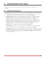
8.2. Command Response
When commands are sent to the CPM, the unit can respond with either verbose (English Text)
or terse messages (numeric / abbreviated). The default message type for all CPM ports can be
set to either terse or verbose by configuring Setup Switch Five.
After the default response message type has been selected via Setup Switch Five, the Port
Configuration (/P) command can be used to specify an individual response message format for
each port. In addition to the Terse and Verbose response modes, the /P command can also
select the Quiet Mode. When the Quiet Mode is selected for a CPM port, that port will not
send messages in response to commands.
The table below summarizes the various response messages for both the Terse and Verbose
modes.
Terse
0
1
2
3
4
5
6
7
8
9
A
Verbose
OK
PORT CONNECT
BUSY
PORT DISCONNECT
INVALID COMMAND
SURE ? (Y/N)
INVALID PARAMETER
INVALID SYNTAX
INVALID ACCESS
INVALID PORT TYPE
COMMAND ABORTED
8-2
CPM Series - Control Port Managers, User's Guide
Command Reference Guide
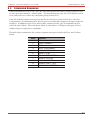
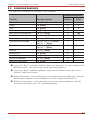
8.3. Command Summary
The chart below summarizes all available CPM Commands:
Command Availability
All
(Admin.)
Basic
(User)
/^E [Enter]
X
X
Sleep
/X [Enter]
X
X
Help
/H [Enter]
X
X
Status
/S [Enter]
X
X
Who (View Port Parameters
/W [n] [Enter]
X
XÊ
Connect
/C <n> [n] [Enter]
X
XË
Resident Disconnect Ì
[Enter]+++[Enter]
X
X
Third Party Disconnect Í
/D[/Y] <n> [n] [Enter]
/D[/Y] * [Enter]
X
Erase Buffer
/E[/Y] <n> [Enter]
/E[/Y] * [Enter]
X
Initialize
/I[/Y] [Enter]
X
Enter Site ID
/F [Enter]
X
Read Site ID
/J [Enter]
X
Set Port Parameters
/P <n> [Enter]
X
Read Port Parameters
/U [Enter]
X
Function
Command Syntax
Wake-up
X
Ê A port with "Basic" command capability cannot view parameters for a port configured for
the Modem Mode. This prevents passwords from being displayed.
Ë A port with "Basic" command capability can perform a Resident Connect, but cannot
perform a Third Party Connect.
Ì Resident Disconnect: Used to disconnect your resident port from another port. Note that
the Disconnect Sequence can be redefined via the Port Configuration Menu (/P).
Í Third Party Disconnect: Used to disconnect two or more non-resident ports. Must be
issued from a third port with "All" command capability.
8-3
CPM Series - Control Port Managers, User's Guide
Command Reference Guide
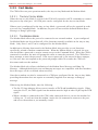
8.4. Command Set
Wake Up (Access Command Mode)
(/^E)
Waking a port will provide access to the CPM command mode, allowing the user to enter
commands to connect ports, display status and etc.. When the Command Mode is inactive, the
CPM will not respond to any commands except the /^E command.
Command Availability: All (Administrator) / Basic (User)
Command Format: /^E [Enter]
CPM Response: The CPM will respond as follows:
Any-to-Any Mode: The "CPM>" prompt will appear.
Modem Mode: The CPM will display the "ENTER PASSWORD" prompt. When the correct
password is entered, the "CPM>" prompt will appear. After three unsuccessful attempts to
enter the password, the port will be put back to sleep.
Sleep (Exit Command Mode)
(/X)
Puts the Port to sleep and exits the CPM Command Mode. While a port is sleeping, the unit
will not recognize any CPM commands except the /^E (Wake Up) command. Note that exiting
from the Command Mode will not terminate user-specified port connections. The /X Command
functions as follows:
· Any-to-Any mode: Exits the CPM Command Mode. When the Command Mode is
inactive, the port will not respond to any command except the Wake-up command (/^E).
· Modem mode: Disconnects and resets the modem. The hang-up message is sent, the
hardware line to modem drops for 250ms and the reset message is sent.
Command Availability: All (Administrator) / Basic (User)
Command Format: /X [Enter]
CPM Response: (Terse and Verbose) PORT ASLEEP
Help
(/H)
Displays a Help Screen, which lists all CPM commands along with a brief description of each
command.
Command Availability: All (Administrator) / Basic (User)
Command Format: /H [Enter]
CPM Response: Displays Help Screen
8-4
CPM Series - Control Port Managers, User's Guide
SYSTEM STATUS
Command Reference Guide
VERSION 1.4
MEMORY 512KB
PORT |
NAME
| STATUS | BAUD | B/P | HS | MODE | TIMEOUT | BUFF | CTS
------+----------+--------+------+-----+------+--------+---------+------+---01 | SYSOP
|*FREE
| 9600 | 8N | DTR | ANY
|
OFF
| ---- | H
02 | MODEM
| C-05
| 9600 | 8N | DTR | MODEM | 5 MIN | ---- | H
03 | SALES1
| FREE
| 9600 | 8N | DTR | ANY
|
OFF
| ---- | L
04 | SALES2
|*FREE
| 9600 | 8N | DTR | ANY
|
OFF
| ---- | L
05 | SALES3
| C-02
| 9600 | 8N | DTR | ANY
|
OFF
| ---- | H
06 | SALES4
| FREE
| 9600 | 8N | XON | ANY
| 15 MIN | ---- | L
07 | ENGR1
|*FREE
| 9600 | 8N | DTR | ANY
| 5 SEC | ---- | L
08 | ENGR2
| C-09
| 9600 | 8N | DTR | ANY
|
OFF
| ---- | H
|
|
|
|
|
|
|
|
|
09 | ENGR3
| C-08
| 9600 | 8N | DTR | ANY
| 5 MIN | ---- | H
10 | RPB
|*FREE
| 9600 | 8N | DTR | ANY
|
OFF
| ---- | L
11 | AND1
|*FREE
| 9600 | 8N | DTR | ANY
|
OFF
| ---- | H
12 |
| FREE
| 9600 | 8N | DTR | ANY
| NONE
| ---- | L
13 |
| FREE
| 9600 | 8N | DTR | ANY
|
OFF
| ---- | L
14 |
| FREE
| 9600 | 8N | DTR | ANY
|
OFF
| ---- | L
15 |
| FREE
| 9600 | 8N | DTR | ANY
| BOTH
| ---- | L
16 |
| FREE
| 9600 | 8N | DTR | ANY
|
OFF
| ---- | L
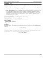
Figure 8.1: The Status Screen
Status
(/S)
Displays the Status Screen (Figure 8.1), which lists current conditions and parameters for all
CPM ports.
Command Availability: All (Administrator) / Basic (User)
Command Format: /S [Enter]
CPM Response: Status screen.
The Status Screen lists the following parameters:
Port: The Port Number.
Name: The user-defined Port Name.
Status: Indicates the current status of each port as follows:
*: Indicates the port has accessed the CPM Command Mode.
FREE: Indicates the port is not in use.
C-nn: Indicates the port is connected to Port number "nn".
Baud: Lists the Port's baud rate.
B/P: Lists the port's data bits and parity settings.
HS: Lists the port's handshaking setting: XON/XOFF, DTR, BOTH, or NONE.
Mode: Lists the user-selected port mode. The Mode column will list either the Any-to-Any
Mode or the Modem Mode for each port. Note that the Modem Mode is only available to
Ports 1 and 2.
8-5
CPM Series - Control Port Managers, User's Guide
Command Reference Guide
Timeout: Indicates the status of the no data timeout feature. When the Timeout feature is
disabled, this column will read "OFF". When the Timeout feature is enabled, this column
will list the user-defined Timeout period.
Buff: Lists the amount of data currently stored in the buffer for this port. The CPM will
allocate buffer memory in blocks of 2K characters. If necessary, the /E command can be
issued from a port with "All" command capability to clear data from port buffers.
CTS: Lists the status of the port's input hardware signal. H is (high) active and L is (low)
inactive.
Who (View Port Parameters) (/W)
Displays the current configuration of an individual port, but does not allow the user to change
port parameters.
Note: When this command is issued from a port with Basic (User) command
capabilities, the CPM will not display parameters for any port configured for the
Modem Mode. This prevents the port password from being displayed.
Command Availability: All (Administrator) / Basic (User)
Command Format: /W [n ] [Enter]
Where "n" is the number or name of the desired port.
CPM Response: Displays port parameters.
Examples:
To display parameters for your resident port, access the CPM Command Mode and type the
following:
/W [Enter]
To display parameters for Port 7, access the CPM Command Mode and type the following:
/W 07 [Enter]
To display parameters for a port named "SALES", access the CPM Command Mode and type
the following:
/W SALES [Enter]
8-6
CPM Series - Control Port Managers, User's Guide
Connect
Command Reference Guide
(/C)
Establishes a bi-directional connection between two ports. There are two different types of
CPM port connections:
· Resident Connect: If the /C command specifies one port name or number, the CPM will
connect your resident port with the specified port.
· Third Party Connect: If the /C command specifies two port numbers or names, the CPM
will connect the two ports indicated by the command. Note that a Third Party Connect
command must be issued from a third port, which has been granted access to "All" CPM
commands. Ports which have been configured for "Basic" command capability cannot
perform a Third Party Connect.
Command Availability: All (Administrator) / Basic (User)
Command Format: /C <n> [n] [Enter]
Where n is the number or name of the port(s) to be connected.
CPM Response:
Verbose: PORT CONNECT
Terse: 1
Examples:
Resident Connect: To connect your resident port to Port 16, access the CPM Command Mode
and type:
/C 16 [Enter]
Third Party Connect: To connect Port 12 to Port 14, access the CPM Command Mode from a
third port with "All" command capability and type the following:
/C 12 14 [Enter]
8-7
CPM Series - Control Port Managers, User's Guide
Third Party Disconnect
Command Reference Guide
(/D)
When two ports are connected, the /D command can be invoked at a third port with "All"
command capabilities. Note that the /D command cannot be used to disconnect your resident
port. To disconnect your resident port, issue the Logoff Sequence (Default =
[Enter]+++[Enter]) or wait for the Timeout Period to elapse (if enabled).
Command Availability: All (Administrator)
Command Format: /D[/Y] <n> [n] [n] [Enter]
Where:
/Y
n
(Optional) suppresses the "SURE? (Y/N)" prompt.
Is the number or name of the port(s) to be disconnected.
To disconnect all ports, enter an asterisk.
CPM Response:
Verbose: SURE? (Y/N), if Y is entered, the CPM will respond with "PORT DISCONNECT".
Terse: 5, if Y is entered, the CPM will respond with 3.
Examples:
To disconnect Port 2 from Port 3, invoke either of the following commands from a third port
with "All" Command Capability:
/D 2 [Enter] or /D 3 [Enter]
To disconnect Port 2 from Port 3 without the "SURE? (Y/N)" prompt, access the CPM
Command Mode from a third port with "All" command capability and type one of the following
commands:
/D/Y 2 [Enter] or /D/Y 3 [Enter]
To disconnect a group of ports with similar names (e.g. PC1, PC2, PC3), access the CPM
Command Mode from another port with "All" command capability and type the following:
/D PC [Enter]
To disconnect all ports, access the CPM Command Mode from a port with "All" command
capability and type the following:
/D * [Enter]
8-8
CPM Series - Control Port Managers, User's Guide
Erase Buffer
Command Reference Guide
(/E)
Erases data from the buffer for a specified port.
Note: Buffered data which has been cleared by the /E command cannot be
recovered.
Command Availability: All (Administrator)
Command Format: /E[/Y] <n>
Where:
n
/Y
is the specified port number. To erase buffers for all ports, enter an asterisk
in place of the port number.
suppresses the "SURE? (Y/N)" prompt
CPM Response:
Verbose: SURE? (Y/N), if Y is entered, the CPM will respond with "OK".
Terse: 5, if Y is entered, the CPM will respond with 0.
Examples:
To clear the buffer for Port 3, access the CPM Command Mode from a port with "All"
command capability and type the following:
/E 3 [Enter]
To clear all port buffers, without displaying the "SURE? (Y/N)" prompt, access the CPM
Command Mode from a port with "All" command capability and type the following:
/E/Y * [Enter]
Initialize
(/I)
Tests the CPM's internal memory and initializes the system with the default parameters
specified by the Setup Switch configuration.
Caution: When the /I command is invoked, the CPM will revert to the
parameters specified by the Set-Up Switch configuration. Any command
selected parameters will be lost.
Command Availability: All (Administrator)
Command Format: /I[/Y] [Enter]
Where /Y is a command option used to suppress the "SURE? (Y/N)" prompt.
CPM Response:
Verbose: SURE? (Y/N), if Y is entered, the CPM will begin the memory test and
initialization sequence.
Terse: 5, if Y is selected, the CPM will begin the memory test and initialization sequence.
8-9
CPM Series - Control Port Managers, User's Guide
Enter Site ID
Command Reference Guide
(/F)
When your application involves communication with several CPM units, the Site I.D. can be
used to indicate the location or name of each unit. The Site I.D. message can be up to 32
characters long, and cannot include non-printable ASCII codes such as NULS and Line Feeds.
Command Availability: All (Administrator)
Command Format: /F [Enter]
CPM Response: (Verbose and Terse) ENTER SITE ID.
Read Site ID
(/J)
Displays the user-defined Site I.D. message.
Command Availability: All (Administrator) / Basic (User)
Command Format: /J [Enter]
CPM Response: Displays Site I.D. Message
Set Port Parameters
(/P)
Displays a menu which allows the user to select options and parameters for an individual port.
Note: When the unit is initialized (using the /I command or the SET and CLEAR
buttons), parameters selected via the /P command will revert to the defaults
specified by the Setup Switch configuration.
Please refer to Section 5.3 for a detailed description of the procedure for defining Port
Parameters.
Command Availability: All (Administrator)
Command Format: /P <n> [Enter]
Where n is the number or name of the port to be configured.
CPM Response: The Port Parameters Menu will be displayed.
Read Port Parameters
(/U)
Sends configuration parameters to an ASCII text file as described in Section 7. When the /U
command is invoked, the system will send a series of command lines describing current port
configuration.
Command Availability: All (Administrator)
Command Format: /U [Enter]
CPM Response: The CPM will send a series of command lines.
8-10
A. Description of System Interfaces
A.1. RS-232 Ports
Figure A.1: RS-232 Port Connectors
A.1.1. Circuitry at Ports 1 and 2 (Modem Ports)
Figure A.2: Circuitry at Ports 1 and 2 (Modem Ports)
A.1.2. Circuitry at Ports 3 and Above
Figure A.3: Circuitry at Ports 3 and Above
Apx-1
CPM Series - Control Port Managers, User's Guide
Appendices
A.2. Snap Adapters
Figures A.4 and A.5 below describe several WTI Snap Adapters commonly used with the CPM
unit. The CPM uses the AT&T wiring standard.
Figure A.4: Snap Adapter Interface
Figure A.5: Snap Adapters
Apx-2
CPM Series - Control Port Managers, User's Guide
Appendices
A.3. Cables
The following 6-wire, straight wired RJ11 cables are available from WTI.
Part No.
Length
Part No.
Length
AC-5
5 ft.
AC-50
50 ft.
AC-10
10 ft.
AC-100
100 ft.
AC-15
15 ft.
AC-150
150 ft.
AC-25
25 ft.
RJC-6
Extension Cable Coupler
The CPM will accept any 6-wire, straight wired RJ11 cables. Do not use standard crossover
(phone) cables. Refer to the Figure below to determine if your cable is straight wired, or
crossover.
Figure A.6: Straight Cables
Note: Make sure your baud rate / cable combinations do not exceed the speed /
lengths shown below:
Baud
Feet
9600
19.2K
38.4K
750
500
300
Apx-3
CPM Series - Control Port Managers, User's Guide
Appendices
B. Specifications
Interface: 16 RS232C serial inputs use RJ11 connectors - which require 4-wire straight RJ11
cables and modular adapters and 6-wire cable if using CTS/DTR flow control.
Coding: Asynchronous, 7/8 bits ASCII.
Parity: Even, Odd, None
Stop Bits: 1 or 2.
Data Rate: 300 to 38.4K BPS (all standard rates).
Flow Control: XON/XOFF, CTS/DTR, Both, or None.
Timeout: No activity timeout disconnects port. None, 1, 5, 10, 15 seconds, 1, 5, 15, 30
minutes.
Memory: Non-volatile 256K (512K optional) battery-backed SRAM SIMMs (some models
may use DIPs). Auto configuring, dynamically allocated.
Setup Switch: 8 position, sets default parameters for baud rate, flow control and port mode.
LEDs: Power On, Ready, Data Activity for Ports 1-16.
Temperature: 0°C to 50°C (operating)
Power: Internal 115/230 VAC 50/60 Hz, 5 watts
Size: 1.75" x 17.0" x 6.5" (H x W x D)
Weight: 6 lbs. shipping weight
Apx-4
CPM Series - Control Port Managers, User's Guide
C.
Appendices
FCC Notice
This equipment has been tested and found to comply with the limits for a Class A digital
device, pursuant to Part 15 of the FCC Rules. These limits are designed to provide reasonable
protection against harmful interference when the equipment is operated in a commercial
environment. This equipment generates, uses, and can radiate radio frequency energy and, if
not installed and used in accordance with the instruction manual, may cause harmful
interference to radio communications. Operation of this equipment in a residential area is
likely to cause harmful interference in which case the user will be required to correct the
interference at his own expense.
D. Customer Service
Customer Service hours are from 8:00 AM to 5:00 PM, PST, Monday through Friday. When
calling, please be prepared to give the name and make of the unit, its serial number and a
description of its symptoms. If the unit should need to be returned for factory repair it must be
accompanied by a Return Authorization number from Customer Service.
WTI Customer Service
5 Sterling
Irvine, California 92618
949-586-9950
Toll Free: 1-800-854-7226
Fax: 949-583-9514
Email: [email protected]
Trademark and Copyright Information
WTI and Western Telematic are trademarks of Western Telematic Inc.. All other product names
mentioned in this publication are trademarks or registered trademarks of their respective
companies.
Information and descriptions contained herein are the property of Western Telematic Inc..
Such information and descriptions may not be copied, disseminated, or distributed without the
express written consent of Western Telematic Inc..
© Copyright Western Telematic Inc. 1995, 2000.
September 1995, June 2000
Part Number: 12348 Revision: B
Apx-5