1
Worked Example 8
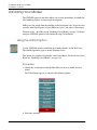
Using the SMD Options
5.
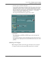
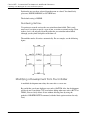
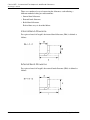
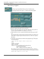
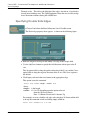
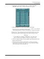
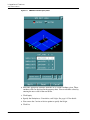
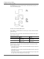
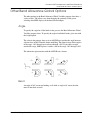
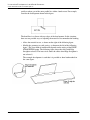
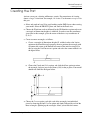
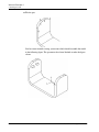
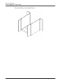
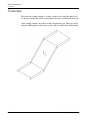
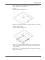
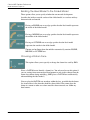
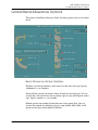
Choose the Fla option from the Bend Allowance Local menu to create two
flanges. Offset the curved edge by 15 mm.
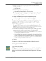
6.
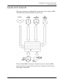
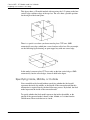
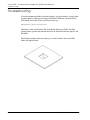
Click Go.
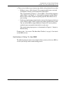
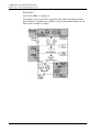
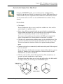
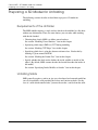
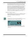
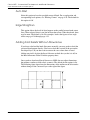
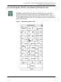
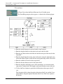
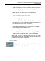
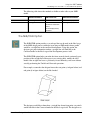
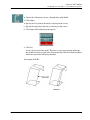
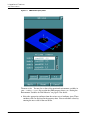
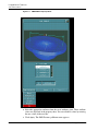
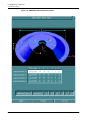
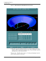
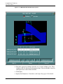
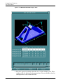
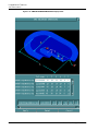
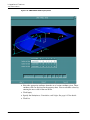
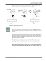
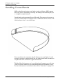
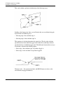
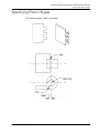
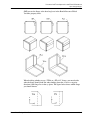
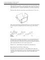
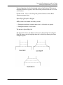
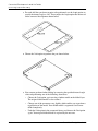
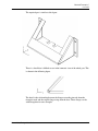
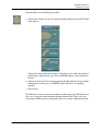
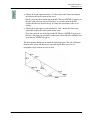
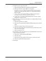
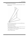
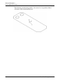
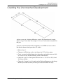
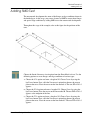
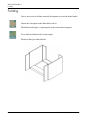
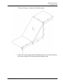
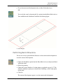
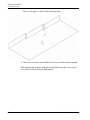
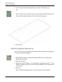
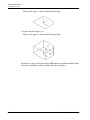
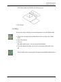
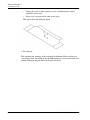
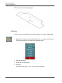
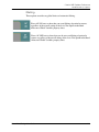
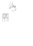
This will result in the following figure.
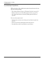
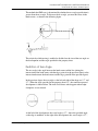
7.
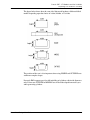
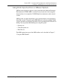
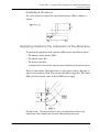
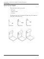
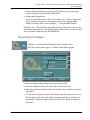
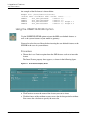
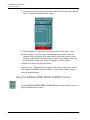
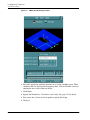
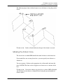
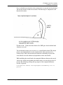
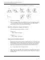
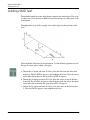
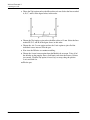
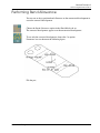
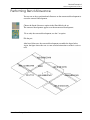
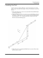
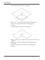
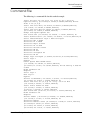
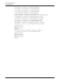
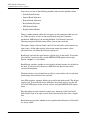
Choose Insert Line option to insert lines, use the location loc[0, 0, 0], with the
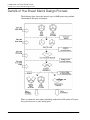
values Dx -60 Dy -60 Dx 60.
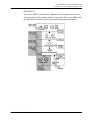
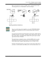
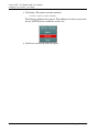
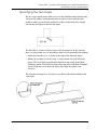
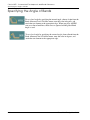
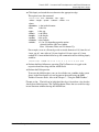
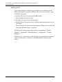
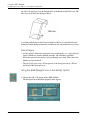
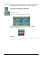
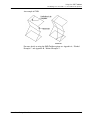
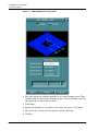
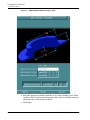
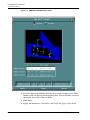
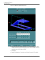
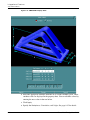
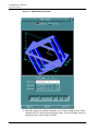
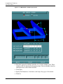
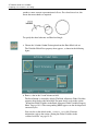
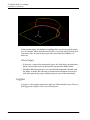
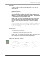
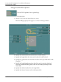
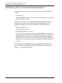
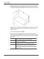
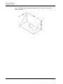
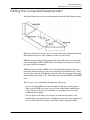
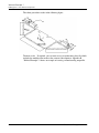
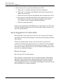
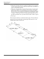
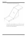
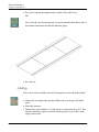
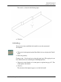
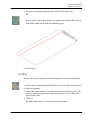
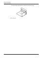
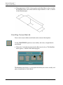
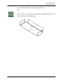
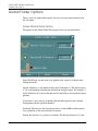
This will result in the following figure.
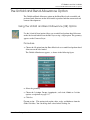
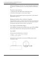
8.
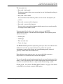
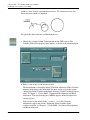
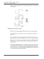
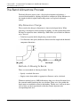
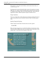
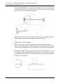
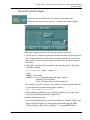
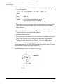
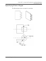
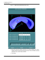
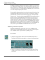
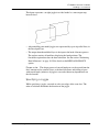
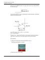
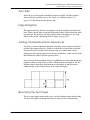
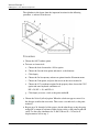
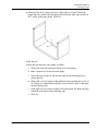
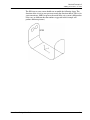
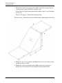
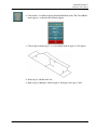
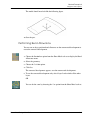
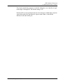
Choose Insert Fillet option from the Model task set to add a fillet with radius
20 mm to the edge b of the profile abcd, towards the center of the developed
model with flanges.
9.
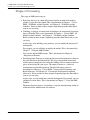
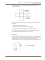
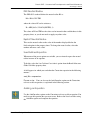
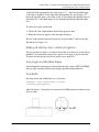
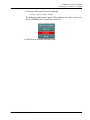
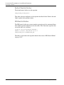
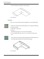
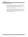
Choose the Join Pcurve option on the Model task set to create a Pcurve from
the lines you have created.
Sheet Metal Design User Guide
H-5