1
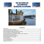
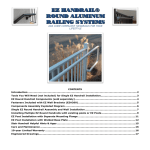
EZ HANDRAIL®
GLASS & ALUMINUM
RAILING SYSTEMS
CODE COMPLIANT RAILING FOR YOUR LIFESTYLE
CONTENTS
Introduction ......................................................................................................................................................................................2
Tools You Will Need (not included) .....................................................................................................................................................3
EZ Glass Railing Box Contents .............................................................................................................................................................4
EZ Glass Railing Components ..............................................................................................................................................................5
EZ Glass Railing Assembly Overview ...................................................................................................................................................6
EZ Post Installation with Separate Mounting Flange ............................................................................................................................7
EZ Post Installation with Welded Base Plate .......................................................................................................................................8
Constructing the Bottom Glass Channel Assembly.............................................................................................................................10
Installing the Lower Assembly ..........................................................................................................................................................11
Constructing the Upper Glass Channel Assembly...............................................................................................................................12
Installing the Upper Assembly ..........................................................................................................................................................13
Glass Baluster Layout .......................................................................................................................................................................14
Placing Setting Blocks in Bottom Glass Channel.................................................................................................................................15
Installing the Glass Balusters ............................................................................................................................................................16
Installing the Glass Spline .................................................................................................................................................................17
Installing the Glass Spacers ..............................................................................................................................................................18
Stair Applications and Non 90-degree Angles ....................................................................................................................................19
Stair Railing Helpful Hints & Apps .....................................................................................................................................................20
EZ Gate Instructions .........................................................................................................................................................................21
Care and Maintenance .....................................................................................................................................................................22
10-year Limited Warranty ................................................................................................................................................................22
Engineered Drawings .......................................................................................................................................................................23
Congratulations!
Congratulations! You are on your way to a maintenance free railing system that is easily
assembled and installed. With your EZ Handrail system, you’ll feel safe being protected by the
tremendous strength of its aluminum alloy components, plus be comforted knowing the
hardened powder coated finish will last year after year.
Please take a moment to read the instructions before you begin assembling your EZ Handrail®.
Introduction
Check the contents of EZ Handrail box with these instructions to verify all parts are present. This
will allow you to become familiar with the components of your new EZ Handrail system.
•
•
•
•
•
Inspect all component parts for familiarity
Layout recommended tools
Before cutting any component, know its use – “measure twice and cut once.”
The included wood fasteners are ACQ treated lumber approved.
The included concrete fasteners are for brick and concrete.
EZ Handrail® shown with EZ Posts and Base Covers sold separately.
www.ezhandrail.com for videos
2
Tools You Will Need (not included)
Level
Tape Measure
Chop Saw
(60 tooth
wood blade)
Pencil
Screw or
Impact Gun
¼” Hex Bit
Driver
(2) pcs 10”
2x4 lumber
to support
railing
during
installation
(optional)
Safety
Glasses
5/16” Hex Bit
Driver
Drill Bits:
¼” wood
¼” x 3 ½”
concrete
1/8”
metal/wood
Time Saver Tip: Cut (2) 2x4’s to 6 inches and (2) 2x4’s to 28 inches for residential or 34 inches
for commercial height railing).
www.ezhandrail.com for videos
3
EZ Glass Railing Box Contents
6 Ft. EZ Glass Railing Kit
Qty
Length
Description
1
6’
Top Cap (A)
1
6’
Bottom Channel (C)
2
6’
Glass Channel (B1 & B2)
6
Each
8” Glass Baluster (H)
2
Each
Top Post Mount (E)
2
Each
Bottom Post Mount (D)
1
18’
Glass Spline (G)
12
1”
Setting Block (F)
14
3 3/4”
Glass Spacer (L)
12
1”
Self Tapping Fastener (J)
8
2 1/4”
Tapcon Fastener (N)
8
1 1/2”
ACQ Fastener (M)
`
8 Ft. EZ Glass Railing Kit
Qty
Length
Description
1
8’
Top Cap (A)
1
8’
Bottom Channel (C)
2
8’
Glass Channel (B1 & B2)
8
Each
8” Glass Baluster (H)
2
Each
Top Post Mount (E)
2
Each
Bottom Post Mount (D)
1
25’
Glass Spline (G)
16
1”
Setting Block (F)
18
3 3/4”
Glass Spacer (L)
12
1”
Self Tapping Fastener (J)
8
2 1/4”
Tapcon Fastener (N)
8
1 1/2”
ACQ Fastener (M)
www.ezhandrail.com for videos
4
EZ Glass Railing Components
Top Cap (A)
Bottom Channel (C)
(Preassembled w/ B1
below)
Glass Spline (G)
Setting Block (F)
Glass Channel (B1, B2)
(B1 and C ship
preassembled)
Glass Spacer (L)
Glass Baluster (H)
Mid Support (K)
Top Post Mount (E)
ACQ Fastener (M)
(Wood)
1” Self Tapper (J)
Bottom Post Mount (D)
Tapcon (N)
(Concrete)
www.ezhandrail.com for videos
5
EZ Glass Railing Assembly Overview
Illustration #1
Top Post Mount
(E)
(G)
(L)
(L)
(G)
8” Wide Glass Balusters Top Cap Assembly
(H)
( A )( B1 )
(G)
(L)
(L)
Bottom Post Mount
(D)
(G)
(L)
(G)
(L)
(G)
(L)
(G)
(L)
(G)
(L)
(G)
Glass Spline Glass Spacers
(G)
(L)
(L)
(Not to exceed 3 3/4”)
(G)
(L)
(G)
(L)
(L)
(G)
(L)
Bottom Channel Assembly
( C )( B2 )
EZ Glass Handrail installed heights are 36” for residential and 42” for commercial.
Always start installation (Glass Spacer or Glass Baluster) at the midpoint of the handrail section.
Note: EZ Posts heights are 38” for residential railing and 44” for commercial railing (sold separately).
This product works with EZ ADA Handrail. Ask you local Home Depot for more information about
EZ ADA Handrail.
www.ezhandrail.com for videos
6
EZ Post Installation with Separate Mounting Flange
Ensure that you have a solid mounting surface for your EZ Post base fasteners. Existing posts
or the EZ Posts (sold separately), may be used with this system. If you are installing EZ Posts,
refer to the steps and illustration below.
Post Mounts are installed with
1. Layout posts uniformly or as desired across entire project.
2. Ensure spacing between posts does not exceed 6 ft. for
elevated decks (or greater than local codes specify).
3. Starting at a corner post, attach post flange to deck/patio
using appropriate fasteners provided with the EZ Post Kit.
MAKE SURE TO USE ADDITIONAL LUMBER BLOCKING
UNDER THE DECK TO SECURELY FASTEN THE FLANGE!!!
In some instances, fully threaded lag screws may be
necessary – but are not included. LAG SCREWS LOOSEN
OVER TIME AND REQUIRE QUARTERLY SAFETY
CHECKS.
4. Slide 3”x3” post over post flange and plum using level.
5. Drill ¼” hole front-to-back through the entire post and post
flange coming out on the back side. IT IS IMPORTANT TO
DRILL HOLES WITH POST LEVEL.
6. Drill 2nd ¼” hole front-to-back. Start hole 1” above the first
hole. The vertical hole pattern creates the best deflection
strength. Note that hole patterns can be modified if
necessary.
7. Fasten post to post flange with 3 ½” bolt, washer, and
standard nut provided. Washers must be placed on both
sides of the post.
8. After post is level and securely fastened, slide decorative
base cover (optional and sold separately) over post covering
the post flange.
9. Secure next post using same procedure. At this point you
may size (cut) and install a railing section to verify your
desired layout. Then continue to set the remainder of the
posts.
IMPORTANT: Install
supporting lumber below
composite/wood decking
when surface mounting
posts to a deck. Fasten
the 4” bolts through the
decking and supporting
underside lumber with
the provided tee nuts.
www.ezhandrail.com for videos
railing sections in STEP 5.
Mounts shown for informational
purpose only in this step.
IMPORTANT: The distance
between posts should not exceed
6 ft. when installed above ground
level. Always refer to your local
building department for building
code clarification.
Note: When
installing the
post base into
ACQ lumber,
use stainless
steel bolts (not
included)
7
EZ Post Installation with Welded Base Plate
Start by ensuring that you have a solid and level mounting surface for your Post(s). Washers or
galvanized/stainless metal shims (not included) may be used to plum posts.
Installation into wood/composite decking/Non ACQ lumber:
STEP 1:
1. Determine the 3”x3” post location(s). Spacing between posts should be 6’
or less to meet IBC codes when installed 24” or higher above the ground.
2. We recommend the edge of the 5”x5” base plate is fastened at least 1 ¾” in
from the edge of the deck (do not lag screw into the rim joist unless
absolutely necessary).
3. Reinforce the decking with support lumber “backer board”. A piece of
2”x10” lumber cut to fit tightly between the joists and installed flat under
the decking works great.
4. Square up the post with the deck and mark all (4) holes with a pencil.
5. At your (4) pencil marks, drill a ¼” hole through the decking and backer
board.
6. Using a 7/16” socket bit in your drill, thread the ¼”x4” Thru Bolt into the
post plate, through the deck, and through the backer board. **
7. Thread the Tee Nut onto the 4” Thru Bolt underneath the decking and
support lumber.
8. Tighten post firmly to deck.
9. Slide on optional post base cover to hide fasteners.
10. Attach post cap after railing has been installed using 1” fasteners
provided.
** Note: The 4” Thru Bolt fits very tightly into the post base plate (especially
Textured Black Posts due to thicker powder coat finish) and in some cases must be
predrilled using a ¼” drill bit.
www.ezhandrail.com for videos
8
Installation into concrete
STEP 1:
www.ezhandrail.com for videos
1. Turn the post upside down on a hard surface and prepare to drill
larger holes in base plate.
Enlarge the (4) existing post base plate holes to 5/16” (using a 5/16”
drill bit).
2. Determine the 3”x3” post location(s). Spacing between posts should
be 6’ or less to meet IBC codes when installed 24” or higher above
the ground.
3. We recommend the edge of the 5”x5” base plate is fastened at least
1 ½” in from the edge of any concrete face (assuming normal weight
concrete).
4. Square up the post with the concrete surface and mark all (4) holes
with a marker.
5. At your (4) marks, drill a 1/4” to 3 ½” or deeper hole into the
concrete using a masonry bit.
6. Fasten post in place with provided ¼” x 3” Powers Wedge Bolts
7. Begin tightening the anchor with socket wrench or impact wrench by
rotating clockwise and applying pressure in toward the concrete.
8. Continue tightening the anchor until the head is firmly seated against
the post base plate. (Do not over tighten).
9. Slide on optional post base cover to hide fasteners.
Attach post cap after railing has been installed using 1” fasteners
provided.
9
Constructing the Bottom Glass Channel Assembly
STEP 1:
1. Measure the distance between your existing posts or newly installed EZ Posts. A
more accurate measurement is taken near the bottom of the posts (Illustration
#2).
2. Subtract a 1/2” from the total measurement to allow your assembly and Bottom
Post Mount to pass the post without scratching the finish. Example: If the
measurement is 60 inches cut C & B1 to 59 1/2 inches.
3. (B1) and (C) ship preassembled from the factory. (Illustration #3).
4. Cut your Bottom Channel (C) and Bottom Glass Channel (B1) to the adjusted
measurement.
www.ezhandrail.com for videos
10
Installing the Lower Assembly
STEP 1:
1. Attach Mid Support (K) underneath the Bottom Assembly t the midpoint of the
railing section (Illustration 3B).
2. Place the Bottom Post Mounts (D) on each end of the Bottom Channel Assembly
making sure the fastener portion is facing up. (Illustration #4).
3. Attach the Bottom Channel Assembly to your post. (The maximum distance from
the decking / flooring to the bottom of the Bottom Glass Channel Assembly is 3
3/4.”(Illustration #4).
4. Suggestion: The width of a 2x4 is 3 1/2,” some contractors will install the
Bottom Channel Assembly by setting it on 2x4’s at both ends.
5. Fasten the Bottom Channel Assembly Post Mounts (D) to the post using the
appropriate fasteners (J, M, N). (See post detail page if necessary).
6. Secure a third fastener (J) through the side of the Top Post Mount (E) securing
the Bottom Channel Assembly to the Bottom Post Mount. This fastener should
be placed on the outside (non viewable side) of the railing as indicated below.
Repeat at the opposite end.
Illustration #3B
Illustration #4
(D)
(J)
Midfoot (K)
www.ezhandrail.com for videos
Spacing is not to exceed 3 ¾” from
the bottom of the channel to the
deck.
11
Constructing the Upper Glass Channel Assembly
STEP 1:
1. Measure the distance between your existing posts or newly installed EZ Posts. A
more accurate measurement is taken 36” from the deck. (Illustration #5).
2. Subtract a 1/2” from the total measurement to allow your assembly and Top
Post Mount to pass the post without scratching the finish. Example: If the
measurement is 60 inches cut A & B2 to 59 1/2 inches.
3. Cut Top Cap (A ) and Top Glass Channel (B2) to the adjusted measurement.
4. Next, snap Top Cap ( A ) with Top Glass Channel (B2). Keep the ends flush.
Start at one end and press together until you hear the pieces snap, then
continue to the other end. (Illustration #6).
5. After the Top Cap Assembly is snapped together, place the Top Post Mounts (E)
on each end making sure the fastener portion is facing down.
Illustration #5
Illustration #6
(E)
(A)
(B2)
36”
Critical Measurement
www.ezhandrail.com for videos
12
Installing the Upper Assembly
STEP 1:
1. The inside dimension of the upper Top Glass Channel Assembly and the lower
Bottom Glass Channel Assembly must be installed exactly 28” apart for the
Glass Balusters to fit properly for residential railings (34” for commercial
railings).
Suggestion: Cut (2) 2x4’s at 28” (if you have not already done so). Place the
2x4’s on end between the assemblies for proper spacing of the Top Assembly.
(Illustration #7). Use 34” 2x4’s for commercial height railing.
2. After locating the placement of the Top Post Mounts, fasten the mounts to the
post using the appropriate fasteners (J, M, N). (See previous post detail).
3. Place a third fastener (J) through the side of the Top Post Mount E) securing the
Top Glass Channel Assembly to the Top Post Mount. This fastener should be
placed on the outside (non viewable side) of the railing as indicated below.
Repeat at the opposite end.
Illustration #7
Illustration #7b
(E)
(B1)
Installed Measurement:
28” Residential
34” Commercial
(B2)
www.ezhandrail.com for videos
(J)
J, M, or N – see previous
post detail page for
appropriate fasteners
13
Glass Baluster Layout
(DO NOT INSTALL GLASS AT THIS POINT)
After you have installed the Top Glass Assembly and Bottom Glass Assembly, you are ready to lay
out your Glass Baluster pattern. Using the chart below determine the appropriate spacing between
Glass Balusters. Lay out the Glass Balusters and Glass Spacers (L) in front of the railing section
using the appropriate spacing. Ensure spacing does not to exceed 3 15/16” in order to comply with
International Building Codes.
The Spacing Table (below right) lists different rail lengths with possible spacing scenarios. These
calculations are not mandatory, only suggestions.
End Space
Mid Spacing
End Space
Center Point for odd number of balusters
Center Point for even number of balusters
www.ezhandrail.com for videos
Rail
Length
96
94
92
90
88
86
84
82
80
78
76
74
72
70
68
66
64
62
60
58
56
54
52
50
48
in.
in.
in.
in.
in.
in.
in.
in.
in.
in.
in.
in.
in.
in.
in.
in.
in.
in.
in.
in.
in.
in.
in.
in.
in.
Approximate Approximate Approximate
End Space Mid Spacing
End Space
2 7/8
1 7/8
7/8
2 1/2
1 1/2
3 3/4
2 3/4
1 3/4
3
2
1
3 5/8
2 5/8
1 5/8
2 1/2
3 3/8
2 5/8
3 1/2
2 1/2
3
1
3 1/2
2
3 3/8
2 3/8
3 3/4
3 3/4
3 3/4
3
3
3 3/4
3 3/4
3 3/4
3
3
3
3 3/4
3 3/4
3 3/4
3 3/4
3
3 3/4
3 3/4
3 3/4
3
3
3 3/4
2
3 3/4
3 3/4
2 7/8
1 7/8
7/8
2 1/2
1 1/2
3 3/4
2 3/4
1 3/4
3
2
1
3 5/8
2 5/8
1 5/8
2 1/2
3 3/8
2 5/8
3 1/2
2 1/2
3
1
3 1/2
2
3 3/8
2 3/8
Quantity of
Glass
Balusters
8
8
8
8
8
7
7
7
7
7
7
6
6
6
6
6
5
5
5
5
5
5
5
4
4
14
Placing Setting Blocks in Bottom Glass Channel
STEP 1:
1. Place two Setting Blocks (F) in the Bottom Glass Channel Assembly for each
Glass Baluster (H). Make sure the water relief channel is facing down. Use
silicone caulk (sold separately on top of setting blocks to secure glass in place.
Do not install glass at this time. The Top Assembly does not require setting
blocks.
Note: Use silicone caulk to hold Setting Blocks (F) in place for stair or ramp
installations. (Silicone caulk sold separately).
(F)
Note: Glass installed
at next step
Illustration #8
Setting Block (F)
2 pcs per
baluster
(F)
(F)
Water relief channel
www.ezhandrail.com for videos
15
Installing the Glass Balusters
STEP 1:
1. Ensure the Setting Blocks
(F) are 1/2 inch in on each
side of the Glass Balusters.
(Illustration #11). Glass
must rest on the Setting
Blocks.
Illustration #9
Glass Baluster
(H)
½” from edge
STEP 2:
1. Starting with the most
middle Glass Baluster, lift
the Glass Baluster up into
the Top Assembly. Swing
the baluster over the
Bottom Assembly into
position. Gently set the
glass onto the caulked
setting block.
www.ezhandrail.com for videos
16
Installing the Glass Spline
STEP 1:
1. After checking for the proper glass embedment of 1/2" in., apply the Glass
Spline (G) around your first Glass Baluster (H) at the bottom assembly and
then the top assembly. (Illustration #12)
Illustration #12
Install this baluster first
if your railing section has an
ODD number of glass balusters
(L)
(H)
½” Mininum
embedment
Install this baluster first
if your railing section has an
EVEN number of glass balusters
(H)
www.ezhandrail.com for videos
17
Installing the Glass Spacers
STEP 1:
After installing the midpoint Glass Baluster (H) with four pieces of Glass Spline (G),
it is now time to install the Glass Spacers (L).
MEASURE ALL GLASS SPACERS TO ENSURE UNIFORM SPACING BETWEEN GLASS
BALUSTERS. The standard
Glass Spacer length is approximately 3 3/4.” Trim the spacers as necessary using
a utility knife or razor blade. Code requires gaps between balusters to be less than
4 inches.
Install a spacer firmly against each side of the Glass Baluster at the top and at
the bottom. Glass Spacers will not slide once installed.
Install the next Glass Baluster. Repeat glass installations steps until you have
finished with your EZ Glass Handrail section.
(L)
(L)
(G)
(L)
(G)
(L)
(G)
(L)
(G)
Glass Spline (G)
www.ezhandrail.com for videos
(G)
(G)
(L)
(L)
(L)
(G)
(L)
(G)
(L)
(G)
(L)
(G)
(L)
(G)
(L)
(G)
(L)
Glass Spacer (L)
18
Stair Applications and Non 90-degree Angles
This kit is manufactured for level runs only. For stair installations, custom Glass
Balusters must be ordered through The Home Depot. One EZ Handrail Pivot
Mount Kit (EZPMW) is required for each stair section as well. (Illustration #13)
stair components).
Illustration #13
Stair slope required to order
custom sized glass balusters
for stairs
www.ezhandrail.com for videos
19
Stair Railing Helpful Hints & Apps
Tip#1: Use rise and run chart for quick stair angle measurement
RISE
5"
5.25"
5.5"
5.75"
6"
6.25"
6.5"
6.75"
7"
7.25"
7.5"
7.75"
10"
27°
28°
29°
30°
31°
32°
33°
34°
35°
36°
37°
38°
10.5"
25°
27°
28°
29°
30°
31°
31°
33°
34°
35°
36°
36°
11"
24°
26°
27°
28°
29°
30°
30°
32°
32°
33°
34°
35°
RUN (TREAD LENGTH)
11.5"
12"
12.5"
23°
23°
22°
25°
24°
23°
26°
25°
24°
27°
26°
25°
28°
27°
26°
29°
28°
27°
29°
28°
27°
30°
29°
28°
31°
30°
29°
32°
31°
30°
33°
32°
31°
34°
33°
32°
13"
21°
22°
23°
24°
25°
26°
27°
27°
28°
29°
30°
31°
13.5"
20°
21°
22°
23°
24°
25°
26°
27°
27°
28°
29°
30°
14"
20°
21°
21°
22°
23°
24°
25°
26°
27°
27°
28°
29°
Tip#2: Smartphones and tablets have good (free) angle finder apps
Android: Leveler by chkuentz
www.ezhandrail.com for videos
iPhone: Basic Angle Finder by Beginning to
Sign
20
EZ Gate Instructions
EZ Gates can swing left or right depending on the hinge location. Standard hinges and gravity latch
are included with all EZ Gates. Note: Self closing hinges and pool child safety latch sold separately.
Step 1
1. Verify rough opening between posts is 1” greater than width of gate.
2. Set gate in opening and visually identify where hinges will attach to gate for the
desired swing direction.
3. Measure 3” down from the very top of gate and attach hinge to appropriate gate face
using the provided fasteners.
4. Attach 2nd hinge 3” above the very bottom of the gate to the appropriate gate face.
5. Measure 4” down from the very top of gate and attach gate latch arm to
appropriate gate face using the provided fasteners.
6. Place (2) 2x4s on edge in the gate opening so the gate may rest in place while
attaching the hinges to the post.
7. Level gate in position and fasten top hinge to appropriate post face with a single
fastener only.
8. Confirm levelness and attach bottom hinge to post using all three fasteners
9. Complete installation of top hinge with remain two fasteners and remove 2x4’s.
Hold gate latch on latch arm, swing gate closed, mark holes and fasten latch to post.
Available gate sizes:
Typical Railing Heights:
Residential: 36”W x 36”H
Residential: 36”
Commercial 36”W x 42”H
Commercial: 42”
Pool Gate: 36”W x 48”H
Pool Fencing: 48” – 54” (check local codes)
Photo of the EZ Gate in Bronze with
pool code safety hardware:
• Self closing hinges
• Child safety pool latch
www.ezhandrail.com for videos
21
Care and Maintenance
While most powder coat finishes are tougher and much more flexible than conventional solvent
based paints, they are about the same hardness as automotive paint and can scratch. To clean a
powder coated surface, use the same care and methods you would use to clean your car. Gently
wash with a clean, soft cloth and a mild detergent followed by a clear water rinse. Even though
most powder coatings are highly resistant, certain solvents can harm them. Avoid contact with
nail polish remover, paint or lacquer thinner, motor oils, transmission and brake fluids or solvent
based cleaning fluids. If any of these should contact the powder coated surface, immediately
wipe the area with a soft, clean cloth, and wash as described above.
10-year Limited Warranty
MADDEN MANUFACTURING
EZ HANDRAIL LIMITED WARRANTY
1. For a time of 10 years the manufacture warrants that EZ Handrail will not peel or blister as a direct result of defects solely arising
from its manufacture process.
Notice of Claims
To procure performance of Madden Manufacturing ‘s obligation under this warranty, you must simply notify Madden Manufacturing of
your claim within thirty (30) days after the occurrence of damage covered by this warranty. Your notice must be in writing, mailed by
certified mail or delivered to Madden Manufacturing, Warranty Service (PO Box 466 Lake Ozark, MO 65049).
This notice must (a) describe the defect claimed to exist, (b) give your name as it appears on this warranty, (c) give the purchase date
and the name and address of the contractor who installed the product, and (d) include proof of purchase.
Inspection
Madden Manufacturing shall be given a reasonable opportunity to inspect the alleged defect on the property, or it may require a sample
of the installed material sent in, before any repair, refinishing or replacement is begun. Madden Manufacturing or its appointee shall
perform its inspection within one hundred twenty (120) days after receiving notice of the claim unless prevented by weather or other
causes not under its reasonable control in which case Madden Manufacturing will inspect within a reasonable time.
Settlement
If after inspection it is determined that your claim is covered by this warranty, Madden Manufacturing shall, at its option, either, (a)
repair, (b) refinish or (c) replace those panels found to have the defects warranted against or pay an amount in cash equivalent to the
cost of the remedy elected by Madden Manufacturing based upon Madden Manufacturing reserves the right to discontinue any of its
products or make any changes in any of items products or make any changes in any of its products during the term of this warranty. If
the products covered by this warranty are not available, Madden Manufacturing shall have the right to substitute a product that, in
Madden Manufacturing’s sole discretion, is of equal quality or value. It is recognized that, in the event of such substitution, a perfect
match may not always be possible. Your rights under this warranty shall end when Madden Manufacturing makes a repair, refinishing,
replacement or payment under this warranty.
Limitations
Madden Manufacturing cannot be responsible for damages from causes outside of its control. The following are samples of external
causes of product failure which are not manufacturing defects and which are not covered by this warranty:
(a) Normal weathering: normal weathering is defined as exposure to sunlight and extremes of weather and atmosphere which will
cause any colored or painted surface to gradually fade, chalk or suffer an accumulation of surface dirt, stains or fungus. The
www.ezhandrail.com for videos
22
(b)
(c)
(d)
(e)
(f)
severity of any of these conditions depends upon the geographical location of your home, the cleanliness of the air in your area
and many other local influences over which Madden Manufacturing has no control.
Damage caused by faulty or improper installation or application of the EZ Handrail, or settlement, distortion, or warping.
Earthquake, hurricane, tornado, cyclone, gale, lightning, fire, acts of God, flood, wind-borne objects, ice, or weather of a
catastrophic nature as defined by the United States Weather Bureau.
Damage caused by atmospheric pollution, acid rain, salt spray, and other harmful chemicals, fumes or vapors directly applied to
the EZ Handrail or in the atmosphere.
Lap abrasion, vandalism, misuse, physical abuse, riot, insurrection or civil disorder.
Negligence in, or failure to provide, reasonable and necessary maintenance of the EZ Handrail to prevent an accumulation of
surface dirt, chalk, staining, mildew or fungus.
BRIEFLY, WE ASSUME THE RESPONSIBILITY ONLY FOR DAMAGES WHICH ARE CAUSED BY MANUFACTURING DEFECTS IN OUR
PRODUCT. MADDEN MANUFACTURING SHALL NOT BE RESPONSIBLE FOR ANY INJURIES TO PERSONS OR DAMAGES TO
PURCHASER’S PREMISES OR THE CONTENTS THEREIN NOR FOR INCIDENTAL, SPECIAL OR CONSEQUENTIAL DAMAGES. NO
DISTRIBUTOR, DEALER, CONTRACTOR OR APPLICATOR IS AUTHORIZED TO OBLIGATE MADDEN MANUFACTURING IN ANY
MANNER EXCEPT TO AUTHENTICATE THE ISSUANCE OF THIS WARRANTY.
Validation and Commencement of Warranty
This warranty shall not be valid or enforceable
(a) If it is not registered with Madden Manufacturing within 30 days after completion of installation of the product covered hereby
by completing and delivering the registration form attached hereto to Madden Manufacturing,
(b) If any statement thereon or any claim for defect shall be false.
(c) If the registration form does not contain your true signature. The registration form shall be mailed to Madden Manufacturing at
its address shown heron.
Documentation of Issuance
In the event of a claim under this warranty, you agree to supply adequate and reasonable proof upon Madden Manufacturing’s request
that you are the person to whom the warranty was originally issued.
Engineered Drawings
www.ezhandrail.com for videos
23