1
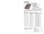
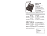
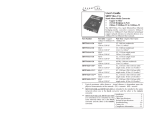
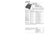
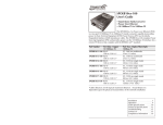
User’s Guide
SCSCF30xx-10x
Stand-Alone Device
• DS3 or T3 / E3
• Coax (BNC) to Fiber
Transition Networks SCSCF30xx-10x series
Devices encode and decode DS3 or E3 coax
copper signals over fiber optic cable to extend
the distance and transmission reliability of highspeed DS3 or E3 data traffic. The SCSCF30xx10x also connects remote locations via T3/E3
cable.
Part Number
SCSCF3011-100
Port One - Copper
75 ohm coax (BNC)
SCSCF3013-100
75 ohm coax (BNC)
SCSCF3014-100
75 ohm coax (BNC)
SCSCF3015-100
75 ohm coax (BNC)
Port Two - Duplex Fiber-Optic
ST, 1300 nm multimode
2 km (1.2 miles)*
SC, 1300 nm multimode
2 km (1.2 miles)*
SC, 1310 nm singlemode
20 km (12.4 miles)*
SC, 1310 nm singlemode
40 km (24.8 miles)*
SCSCF3016-100 75 ohm coax (BNC)
SC, 1310 nm singlemode
60 km (37.3 miles)*
SCSCF3017-100 75 ohm coax (BNC)
SC, 1550 nm singlemode
80 km (49.7 miles)*
SCSCF3018-100 75 ohm coax (BNC)
MT-RJ, 1300 nm multimode
2 km (1.2 miles)*
SCSCF3019-100 75 ohm coax (BNC)
LC, 1310 nm single mode
20 km (12.4 miles)*
SCSCF3029-100 75 ohm coax (BNC)
SC, 1310 mn (TX)/1550 nm (RX)
20 km (12.4 miles)*
SCSCF3029-101 75 ohm coax (BNC)
SC, 1550 mn (TX)/1310 nm (RX)
20 km (12.4 miles)*
SCSCF3029-100 and -101 are intended to be installed in the same network where
one is the local converter and the other is the remote converter.
* Typical maximum cable distance. Actual distance is dependent upon the physical
characteristics of the network.
Note: The CCSCF30xx-10x model is the
chassis version of the Device. For more
information, see the CCSCF30xx-10x user’s
guide on-line at www.transition.com.
Installation . . . . . . . . . . . . . . . . . . . . .2
Operation . . . . . . . . . . . . . . . . . . . . . .6
Cable Specifications . . . . . . . . . . . . . .7
Technical Specifications . . . . . . . . . . .8
Troubleshooting . . . . . . . . . . . . . . . . .9
Compliance Information . . . . . . . . .12
SCSCF30xx-10x
Part Number
SCSCF3029-102
SCSCF3029-103
Port One - Copper
75 ohm coax (BNC)
75 ohm coax (BNC)
Installation -- Continued
Port Two - Single Fiber Optic
SC, 1310 mn (TX)/1550 nm (RX)
40 km (24.8 miles)*
CAUTION: Wear a grounding device and observe electrostatic discharge
precautions when setting the configuration switches. Failure to observe this caution
could result in damage to, and subsequent failure of, the Device.
SC, 1550 mn (TX)/1310 nm (RX)
40 km (24.8 miles)*
SCSCF3029-102 and -103 are intended to be installed in the same network where
one is the local converter and the other is the remote converter.
SCSCF3039-100
75 ohm coax (BNC)
Set the Configuration Switches
The configuration switches are located on the side of the Device. Use a small, flatblade screwdriver to set the recessed switches.
LC, 1300 mn multimode
2 km (1.2 miles)*
*Typical maximum cable distance. Actual distance is dependent upon the physical
characteristics of the network: (TX) = transmit, (RX) = receive.
Switch 1 -- Select DS3 or E3
up
up - Supports a DS3 interface.
Optional Accessories (sold separately)
down - Supports a E3 interface.
Part Number Description
SPS-1872-SA Optional External Power Supply; 18-72VDC Stand-Alone
Output: 12.6VDC, 1.0 A
DS3
down
SPS-1872-PS Optional External Power Supply; 18-72VDC Piggy-back;
Output: 12.6VDC, 1.0 A
E-MCR-04
12-Slot Device Rack (includes universal internal power supply) 17 x
15 x 5 in. (432 x 381 x 127 mm)
WMBL
Optional Wall Mount Brackets; 4.0 in. (102 mm)
WMBV
Optional Vertical Mount Bracket; 5.0 in. (127 mm)
WMBD
Optional DIN Rail Mount Bracket; 5.0 in. (127 mm)
WMBD-F
Optional DIN Rail Mount Bracket (flat); 3.3in. (84 mm)
E3
Switch 2 -- Coax Line Build Out (DS3 only)
up
up - The DS3 line is set up to operate at distances up to 225
ft. (68.6 m).
down - The DS3 line is set up to operate at distances greater
than 225 ft. (68.6 m).
<225 ft (68.6 m)
down
>225 ft (68.6 m)
Installation
Set the Loop-Back Switch
up
Switch 3 -- Signal on Loss of Carrier
The loop-back switch is located on the front panel of the Device and is used for
installation and network debugging procedures.
up - Transmits an alarm indication signal (AIS) on the loss of
the input carrier (unframed).
To set the switch, use a small flatblade screwdriver or a
similar device (see the drawing to the right).
down - No signal is transmitted on the loss of the input
carrier (unframed).
CL
CL (Coax loop-back)
Enable loop-back on the local coax interface.
--
(Center Position)
Normal operation.
FL
(Fiber loop-back)
Enable loop-back on the local fiber interface.
FL
Note: Three loop-back test scenarios are described in detail on page 10.
Transmit alarm
down
No signal
up
Switch 4 -- Alarm Indication Signal (AIS)
up - AIS is defined as a pattern of alternating 1’s and 0’s
(unframed).
Alarms = 1's and 0'
down - AIS is defined as a pattern of all 1’s (unframed).
down
Alarm = all 1's
2
24-hour Technical Support: 1-800-260-1312 -- International: 00-1-952-941-7600
[email protected] -- Click the “Transition Now” link for a live Web chat.
3
SCSCF30xx-10x
Installation -- Continued
Installation -- Continued
CAUTION: Wear a grounding device and observe electrostatic discharge precautions
when setting the jumper. Failure to observe this caution could result in damage to, and
subsequent failure of, the Device.
Install the Coax Cable
1.
Locate or build coax cables with female connectors installed at both ends.
2.
Connect the coax cables to the Device as described:
•
Connect the female TX cable connector to the male TX port.
•
Connect the female RX cable connector to the male RX port.
Connect the coax cables to the other device (switch, workstation, etc.) as
described:
•
Connect the female TX cable connector to the male RX port.
•
Connect the female RX cable connector to the male TX port.
Set the Coax Grounding Jumpers
Note: Modify the settings for J11 and J12 only if necessary.
3.
Jumpers 11 and 12 (located on the circuit board near the coax ports) provide a
grounding feature so that the SCSCF30xx-10x Device complies with the G.703
specification where:
•
The output coax port is connected to chassis ground.
•
A provision to connect the input coax port to chassis ground is provided.
The factory settings for these two jumpers are:
Jumper 12 (jumpered)
RX
RX
TX
TX
= Output coax port is connected to chassis ground.
Jumper 11 (not-jumpered) = Input coax port is not connected to chassis ground.
J11
No Jumper
Connect the
coax cable to the
Media Converter
as shown
J12
Jumper
The jumpers are located on the circuit board inside the Device housing. To set the
jumpers:
1.
Using a small screwdriver, remove the four (4) screws that secure the cover
and carefully remove the cover from the Device.
2.
Locate the jumper on the circuit board.
Install the Fiber Cable
1.
Locate or build fiber cables with male, two-stranded TX to RX connectors
installed at both ends.
2.
Connect the fiber cables to the local SCSCF30xx-10x Device as described:
•
Connect the male TX cable connector to the female TX port.
•
Connect the male RX cable connector to the female RX port.
Connect the fiber cables to the remote SCSCF30xx-10x Device as described:
•
Connect the male TX cable connector to the female RX port.
•
Connect the male RX cable connector to the female TX port.
3.
4
Connect the
coax cable to the
other device as
shown
3.
Using small needle-nosed pliers or similar device, move the jumper to the
desired position. (Refer to the above drawing.)
4.
Carefully replace the cover on the Device and replace the four (4) screws that
secure the cover to the Device.
24-hour Technical Support: 1-800-260-1312 -- International: 00-1-952-941-7600
RX
RX
TX
TX
Connect fiber cable
to media converter
as shown.
Connect fiber cable
to other device
(media converter,
hub, etc.) as shown
[email protected] -- Click the “Transition Now” link for a live Web chat.
5
SCSCF30xx-10x
Installation -- Continued
Cable Specifications
Power the Device
Coax Cable
DS3 / E3: 75 ohm coax cable with BNC connectors. Peak pulse power in DBm
AC
1.
Connect the barrel connector on the power adapter to the Device’s power
port (located on the back of the Device).
2.
Connect the power adapter plug to AC power.
3.
Verify that the Device is powered by observing the illuminated LED power
indicator light.
Consult the user’s guide for the Transition Networks SPS1872-xx DC external
power supply for powering the Device.
Operation
After installation, the Device should function without operator intervention. Use the
status LEDs to monitor the Device operation in the network.
SDF
Green on
The coax link is up.
Green flashing
The coax link is in loop-back mode.
Yellow on
AIS (Alarm Indication Signal) on the coax link.
Green on
The fiber link is up.
Green flashing
The fiber link is in loop-back mode.
Yellow on
AIS (Alarm Indication Signal) on the fiber link.
PWR Green on
The Device is connected to external power.
TX
PWR
RX
SDF
SDC
Fiber
6
TX output
min: +1.25 dBm
max: +3.25 dBm
RX input
min: -9.47 dBm
max: +9.25 dBm
Fiber Cable
DC
SDC
(Decibel millwatts).
Coax
24-hour Technical Support: 1-800-260-1312 -- International: 00-1-952-941-7600
Singlemode fiber (recommended):
Multimode fiber (recommended):
Multimode fiber (optional):
9 µm
62.5/125 µm
100/140, 85/140, 50/125 µm
SCSCF3011-100
Fiber Optic Transmitter Power:
Fiber Optic Receiver Sensitivity:
Link Budget:
1300 nm multimode
min: -19.0 dBm
max: -14.0 dBm
min: -30.0 dBm
max: -14.0 dBm
11.0 dB
SCSCF3013-100
Fiber Optic Transmitter Power:
Fiber Optic Receiver Sensitivity:
Link Budget:
1300 nm multimode
min: -19.0 dBm
max: -14.0 dBm
min: -30.0 dBm
max: -14.0 dBm
11.0 dB
SCSCF3014-100
Fiber-optic Transmitter Power:
Fiber-optic Receiver Sensitivity:
Link Budget:
1310 nm singlemode
min: -15.0 dBm
max: -8.0 dBm
min: -31.0 dBm
max: -8.0 dBm
16.0 dB
SCSCF3015-100
Fiber Optic Transmitter Power:
Fiber Optic Receiver Sensitivity:
Link Budget:
1310 nm singlemode
min: -8.0 dBm
max: -2.0 dBm
min: -34.0 dBm
max: -7.0 dBm
26.0 dB
SCSCF3016-100
Fiber-optic Transmitter Power:
Fiber-optic Receiver Sensitivity:
Link Budget:
1310 nm singlemode
min: -5.0 dBm
max: 0.0 dBm
min: -34.0 dBm
max: -7.0 dBm
29.0 dB
SCSCF3017-100
Fiber-optic Transmitter Power:
Fiber-optic Receiver Sensitivity:
Link Budget:
1550 nm singlemode
min: -5.0 dBm
max: 0.0 dBm
min: -34.0 dBm
max: -7.0 dBm
29.0 dB
SCSCF3018-100
Fiber-optic Transmitter Power:
Fiber-optic Receiver Sensitivity:
Link Budget:
1300 nm multimode
min: -19.0 dBm
max: -14.0 dBm
min: -33.5 dBm
max: -14.0 dBm
14.5 dB
SCSCF3019-100
Fiber-optic Transmitter Power:
Fiber-optic Receiver Sensitivity:
Link Budget:
1310 nm single mode
min: -15.2 dBm
max: -8.0 dBm
min: -32.5 dBm
max: -3.0 dBm
17.3 dB
SCSCF3029-100
SCSCF3029-101
Fiber-optic Transmitter Power:
Fiber-optic Receiver Sensitivity:
Link Budget:
1310 nm (TX) / 1550 nm (RX) simplex
1550 nm (TX) / 1310 nm (RX) simplex
min: -13.0 dBm
max: -6.0 dBm
min: -32.0 dBm
max: -3.0 dBm
19.0 dB
[email protected] -- Click the “Transition Now” link for a live Web chat.
7
SCSCF30xx-10x
Cable Specifications -- Continued
SCSCF3029-102
SCSCF3029-103
Fiber-optic Transmitter Power:
Fiber-optic Receiver Sensitivity:
Link Budget:
1310 nm (TX) / 1550 nm (RX) simplex
1550 nm (TX) / 1310 nm (RX) simplex
min: -8.0 dBm
max: -3.0 dBm
min: -33.0 dBm
max: -3.0 dBm
25.0 dB
CSCSCF3039-100
Fiber-optic Transmitter Power:
Fiber-optic Receiver Sensitivity:
Link Budget:
1300 nm multimode
min: -19.0 dBm
max: -14.0 dBm
min: -30.0 dBm
max: -14.0 dBm
11.0 dB
Troubleshooting
If the Device fails, isolate and correct the failure by determining the answers to the
following questions and then taking the indicated action:
1.
•
•
The fiber optic transmitters on this device meet Class I Laser safety requirements per
IEC-825/CDRH standards and comply with 21 CFR1040.10 and 21CFR1040.11.
•
•
For use with Transition Networks Model SCSCF30xx-10x or equivalent
DS3 / T3 = 44.7 Mb/s; E3 = 34.4 Mb/s
Dimensions
3.25" x 4.7" x 1.0" (83 mm x 119 mm x 25 mm)
Weight
10 oz. (283 g) approximately
Power Consumption
6.0 Watts
Power Supply
DC Outlet
12 VDC, 0.8 Amp (minimum)
Minimum output regulation: 5%
MTBF (stand alone)
48,996 (MIL217F2 V5.0) (MIL-HDBD-217F)
119,854 (Bellcore7 V5.0)
Environment
Tmra*:
Storage Temp:
Humidity:
Altitude:
Warranty
2.
FCC Class A; EN 55022 Class A; EN 55024; ANSI
T1.102-1993; ETSI TBR-24; ITU-T G.703 G.823 for jitter
tolerance; G.775 for loss of signal; Telecordia GR499CORE & GR-253-CORE
Data Rate
0 to 50°C (32° to 122°F )
-20° to 85°C (-4° to 185°F)
5 to 95%, non condensing
0 to 10,000 feet
•
•
•
3.
Proceed to step 3.
Is the SDF (Signal Detect / Fiber) LED illuminated green?
NO
•
•
•
Check the fiber cables for proper connection.
Verify that the TX and RX cables on the local Device are connected to
the RX and TX ports, respectively, on the remote Device.
Contact Tech Support: 1-800-260-1312, Int’l: 00-1-952-941-7600.
YES
•
4.
Proceed to step 4.
Is the SDC (Signal Detect / Coax) LED flashing green?
YES
•
•
The coax link is in loop-back mode. For normal operation, set the loopback switch to the center (normal) position.
Contact Tech Support: 1-800-260-1312, Int’l: 00-1-952-941-7600.
NO
•
CAUTION: Visible and invisible laser radiation when open. Do not stare into beam
or view directly with optical instruments.
Check the coax cables for the proper connection.
Contact Tech Support: 1-800-260-1312, Int’l: 00-1-952-941-7600.
YES
*Manufacturer’s rated ambient temperature.
Product is certified by the manufacturer to comply with DHHS Rule 21/CFR,
Subchapter J applicable at the date of manufacture.
Proceed to step 2.
Is the SDC (Signal Detect / Coax) LED illuminated green?
NO
Lifetime
For the most up-to-date information on the SCSCF30xx-10x Device, view the user’s
guide on-line at www.transition.com.
Ensure that the power adapter is the proper type of voltage and cycle
frequency for the outlet.
Ensure the power adapter is properly installed in the Device and in the
grounded outlet.
Contact Tech Support: 1-800-260-1312, Int’l: 00-1-952-941-7600.
YES
Technical Specifications
Standards
Is the PWR (Power) LED on the Device illuminated?
NO
5.
Proceed to step 5.
Is the SDF (Signal Detect / Fiber) LED flashing green?
YES
•
•
The fiber link is in loop-back mode. For normal operation, set the loopback switch to the center (normal) position.
Contact Tech Support: 1-800-260-1312, Int’l: 00-1-952-941-7600.
NO
•
Proceed to step 6.
CAUTION: Use of controls, adjustments or the performance of procedures other
than those specified herein may result in hazardous radiation exposure.
8
24-hour Technical Support: 1-800-260-1312 -- International: 00-1-952-941-7600
[email protected] -- Click the “Transition Now” link for a live Web chat.
9
SCSCF30xx-10x
6.
7.
Is Data Transfer Failing?
YES
•
Is the SDC (Signal Detect / Coax) LED illuminated yellow?
YES
•
Verify the local copper connection by starting a local copper loop-back
(set the loop-back switch on the local Device to “CL”) and then use a bit error
test unit at the local location to run a bit error test.
A failure of the remote unit connected to the coax interface has caused
an Alarm Indication Signal (AIS) on the coax interface. Correct the
remote unit failure.
Copper
•
Local
Converter
Fiber
Remote
Converter
Copper
Coax
Remote
Device
Bit Error
Test Unit
AIS on coax link
•
•
Copper
L ocal
Device
B it E rror
Tes t Unit
Remote
Converter
Proceed to step 8.
Is the SDF (Signal Detect / Fiber) LED illuminated yellow?
YES
•
Fiber
Contact Tech Support: 1-800-260-1312, Int’l: 00-1-952-941-7600.
NO
8.
Local
Converter
A broken coax link has caused an Alarm Indication Signal (AIS) on the
fiber interface. Correct the coax link failure.
Original
Fault
AIS on fiber link
Coax
•
Verify the remote copper connection by starting a local copper loop-back
at the remote location (set the loop-back switch on the remote Device to
“CL”) and then use a bit error test unit at the remote location to run a bit
error test.
•
Fiber
Remote
Converter
Copper
L ocal
Device
B it E rror
Tes t Unit
Local
Converter
Fiber
Coax
Contact Tech Support: 1-800-260-1312, Int’l: 00-1-952-941-7600.
NO
•
Copper
Coax
Original Fault
Verify the local fiber connection by starting a local fiber loop-back at the
remote location (set the loop-back switch on the remote Device to “FL”) and
then use a bit error test unit at the local location to run a bit error test.
Copper
Fiber
Contact Tech Support: 1-800-260-1312, Int’l: 00-1-952-941-7600.
Declaration of Conformity
Name of Mfg:
•
Contact Tech Support: 1-800-260-1312, Int’l: 00-1-952-941-7600.
NO
•
Proceed to step 7.
Transition Networks
10900 Red Circle Drive, Minnetonka MN 55343 U.S.A.
Model:
SCSCF30xx-10x Series Device
Part Number:
SCSCF3011-100, SCSCF3013-100, SCSCF3014-100,
SCSCF3015-100, SCSCF3016-100, SCSCF3017-100,
SCSCF3018-100, SCSCF3019-100, SCSCF3029-100,
SCSCF3029-101, SCSCF3029-102, SCSCF3029-103,
SCSCF3039-100
Regulation:
EMC Directive 89/336/EEC
Purpose: To declare that the SCSCF30xx-10x to which this declaration refers is in
conformity with the following standards.
EN 55022:1998 Class A; EN 55024:1998; FCC Part 15 Subpart B; CFR 21 subpart J
61000-3-2:1995+A14:2000; 61000-3-3:1995;
I, the undersigned, hereby declare that the equipment specified above conforms to the above
Directive(s) and Standard(s).
February, 2009
Stephen Anderson, Vice-President of Engineering
10
24-hour Technical Support: 1-800-260-1312 -- International: 00-1-952-941-7600
Date
[email protected] -- Click the “Transition Now” link for a live Web chat.
11
Compliance Information
CE Mark
CISPR22/EN55022 Class A + EN55024
FCC Regulations
This equipment has been tested and found to comply with the limits for a Class A digital device,
pursuant to part 15 of the FCC rules. These limits are designed to provide reasonable protection
against harmful interference when the equipment is operated in a commercial environment. This
equipment generates, uses, and can radiate radio frequency energy and, if not installed and used in
accordance with the instruction manual, may cause harmful interference to radio communications.
Operation of this equipment in a residential area is likely to cause harmful interference, in which
case the user will be required to correct the interference at the user's own expense.
Canadian Regulations
This digital apparatus does not exceed the Class A limits for radio noise for digital apparatus set
out on the radio interference regulations of the Canadian Department of Communications.
Le présent appareil numérique n'émet pas de bruits radioélectriques dépassant les limites
applicables aux appareils numériques de la Class A prescrites dans le Règlement sur le brouillage
radioélectrique édicté par le ministère des Communications du Canada.
European Regulations
Warning This is a Class A product. In a domestic environment this product may cause radio
interference in which case the user may be required to take adequate measures.
Achtung ! Dieses ist ein Gerät der Funkstörgrenzwertklasse A. In Wohnbereichen können bei
Betrieb dieses Gerätes Rundfunkstörungen auftreten. In Diesem Fäll ist der Benutzer für
Gegenmaßnahmen verantwortlich.
Attention ! Ceci est un produit de Classe A. Dans un environment domestique, ce produit
risque de créer des interférences radioélectriques, il appartiendra alors à l'utilsateur de prende les
measures spécifiques appropriées.
Contact Us
Technical support is available 24 hours a day.
US and Canada: 1-800-260-1312 International: 00-1-952-941-7600
Chat live via the Web with Transition Networks Technical Support.
Log onto www.transition.com and click the Transition Now link.
Transition Networks provides seminars via live web-based training.
Log onto www.transition.com and click the Learning Center link.
Ask a question anytime by sending an e-mail to our technical support staff.
[email protected]
Transition Networks, 10900 Red Cricle Drive, Minnetonka, MN 55343, U.S.A.
telephone: 952-941-7600, toll free: 800-526-9267, fax: 952-941-2322
Trademark Notice
All trademarks and registered trademarks are the property of their respective owners.
Copyright Restrictions
© 2001, 2004 Transition Networks.
All rights reserved. No part of this work may be reproduced or used in any form or by any means
- graphic, electronic, or mechanical - without written permission from Transition Networks.
Printed in the U.S.A.
33216.G