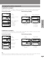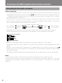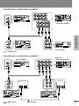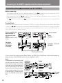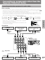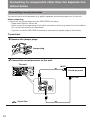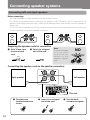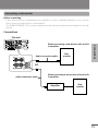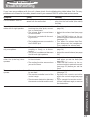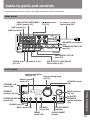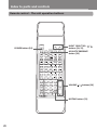
1
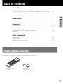
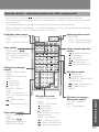
English
A-905X
Before using
Integrated Stereo Amplifier
Connections
Preparations
Instruction Manual
INTEGRATED STEREO AMPLIFIER
VOLUME
WIDE RANGE AMP TECHNOLOGY
INPUT
MD
TUNER
TAPE
LINE-1/ DVD
LINE-2
STANDBY
DIRECT
BASS
POWER
ON
TREBLE
BALANCE
PHONES
SOURCE DIRECT
DIRECT
TONE
OFF
−
+
−
+
L
R
ACOUSTIC
PRESENCE
OFF/1/2
Operation
CD
STANDBY/ON
A-905X
Other Information
Before using
Thank you for purchasing ...
Thank you for purchasing the ONKYO A-905X Integrated Stereo Amplifier.
Please read this manual thoroughly before making any connection or turning on the power. Follow
these instructions to obtain optimum performance and maximum listening enjoyment from your new
A-905X. Please retain this manual for future reference.
Main Features
• Individually designed as the high-quality
Separate Collection Series
• 4 ohm-drive capability with discrete output stage circuit
Memory Preservation
This unit does not require memory preservation batteries. A built-in memory power back-up system preserves the contents of the memory during power failures and even when the unit is unplugged. The unit
must be plugged in order to charge the back-up system.
WARNING:
TO REDUCE THE RISK OF FIRE OR
ELECTRIC SHOCK, DO NOT
EXPOSE THIS APPLIANCE TO RAIN
OR MOISTURE.
CAUTION:
TO REDUCE THE RISK OF
ELECTRIC SHOCK, DO NOT
REMOVE COVER (OR BACK). NO
USER-SERVICEABLE PARTS INSIDE.
REFER SERVICING TO QUALIFIED
SERVICE PERSONNEL.
2
• Input selector for six audio sources
• Remote control operable with
-connected ONKYO components
The memory preservation period after the unit has
been unplugged varies depending on climate and
placement of the unit. On the average, memory contents are protected over a period of a few weeks after the last time the unit has been unplugged. This
period is shorter when the unit is exposed to a highly
humid climate.
WARNING
AVIS
RISK OF ELECTRIC SHOCK
DO NOT OPEN
RISQUE DE CHOC ELECTRIQUE
NE PAS OUVRIR
The lightning flash with arrowhead symbol, within
an equilateral triangle, is intended to alert the user
to the presence of uninsulated “dangerous
voltage” within the product’s enclosure that may
be of sufficient magnitude to constitute a risk of
electric shock to persons.
The exclamation point within an equilateral
triangle is intended to alert the user to the
presence of important operating and maintenance
(servicing) instructions in the literature
accompanying the appliance.
Important Safeguards
1.
Read Instructions – All the safety and
operating instructions should be read before
the appliance is operated.
2.
Retain Instructions – The safety and
operating instructions should be retained for
future reference.
Heed Warnings – All warnings on the
appliance and in the operating instructions
should be adhered to.
4.
Follow Instructions – All operating and use
instructions should be followed.
5.
Water and Moisture – The appliance should
not be used near water – for example, near
a bathtub, washbowl, kitchen sink, laundry
tub, in a wet basement, or near a swimming
pool, and the like.
6.
Carts and Stands – The appliance should
be used only with a cart or stand that is recommended by the manufacturer.
6A. An appliance and cart
combination should be
moved with care. Quick
stops, excessive force, and
uneven surfaces may cause
the appliance and cart
combination to overturn.
PORTABLE CART WARNING
S3125A
7.
Wall or Ceiling Mounting – The appliance
should be mounted to a wall or ceiling only
as recommended by the manufacturer.
8.
Ventilation – The appliance should be situated so that its location or position does not
interfere with its proper ventilation. For example, the appliance should not be situated
on a bed, sofa, rug, or similar surface that
may block the ventilation openings; or if
placed in a built-in installation, such as a
bookcase or cabinet that may impede the
flow of air through the ventilation openings,
there should be free space of at least 20 cm
(8 in.) and an opening behind the appliance.
9.
Heat – The appliance should be situated away
from heat sources such as radiators, heat registers, stoves, or other appliances (including
amplifiers) that produce heat.
11. Polarization – If the appliance is provided with
a polarized plug having one blade wider than
the other, please read the following information:
The polarization of the plug is a safety feature.
The polarized plug will only fit the outlet one
way. If the plug does not fit fully into the outlet, try reversing it. If there is still trouble, the
user should seek the services of a qualified electrician. Under no circumstances should the user
attempt to defeat the polarization of the plug.
Before using
3.
10. Power Sources – The appliance should be
connected to a power supply only of the type
described in the operating instructions or as
marked on the appliance.
12. Power-Cord Protection – Power-supply
cords should be routed so that they are not
likely to be walked on or pinched by items
placed upon or against them, especially near
plugs, convenience receptacles, and the
point where they exit from the appliance.
13. Cleaning – The appliance should be cleaned
only as recommended by the manufacturer.
14. Nonuse Periods – The power cord of the appliance should be unplugged from the outlet
when left unused for a long period of time.
15. Object and Liquid Entry – Care should be taken
so that objects do not fall and liquids are not spilled
into the enclosure through openings.
16. Damage Requiring Service – The appliance
should be serviced by qualified service personnel when:
A. The power-supply cord or the plug has
been damaged; or
B. Objects have fallen, or liquid has been
spilled into the appliance; or
C. The appliance has been exposed to rain; or
D. The appliance does not appear to operate normally or exhibits a marked change
in performance; or
E. The appliance has been dropped, or the
enclosure damaged.
17. Servicing – The user should not attempt to service the appliance beyond that described in the
operating instructions. All other servicing should
be referred to qualified service personnel.
3
Precautions
1. Warranty Claim
You can find the serial number on the rear panel
of this unit. In case of warranty claim, please report this number.
For British model
Replacement and mounting of an AC plug on the
power supply cord of this unit should be performed
only by qualified service personnel.
2. Recording Copyright
Recording of copyrighted material for other than
personal use is illegal without permission of the
copyright holder.
IMPORTANT
The wires in the mains lead are coloured in accordance with the following code:
Blue : Neutral
Brown : Live
As the colours of the wires in the mains lead of
this apparatus may not correspond with the
coloured markings identifying the terminals in your
plug, proceed as follows:
The wire which is coloured blue must be connected
to the terminal which is marked with the letter N
or coloured black.
The wire which is coloured brown must be connected to the terminal which is marked with the
letter L or coloured red.
3. AC Fuse
The fuse is located inside the chassis and is not
user-serviceable. If power does not come on, contact your Onkyo authorized service station.
4. Care
From time to time you should wipe the front and
rear panels and the cabinet with a soft cloth. For
heavier dirt, dampen a soft cloth in a weak solution of mild detergent and water, wring it out dry,
and wipe off the dirt. Following this, dry immediately with a clean cloth. Do not use rough material, thinners, alcohol or other chemical solvents
or cloths since these could damage the finish or
remove the panel lettering.
5. Power
WARNING
BEFORE PLUGGING IN THE UNIT FOR THE FIRST
TIME, READ THE FOLLOWING SECTION CAREFULLY.
The voltage of the available power supply differs
according to country or region. Be sure that the
power supply voltage of the area where this unit
will be used meets the required voltage (e.g., AC
230 V, 50 Hz or AC 120 V, 60 Hz) written on the
rear panel.
Declaration of Conformity
We, ONKYO EUROPE
ELECTRONICS GmbH
INDUSTRIESTRASSE 20
82110 GERMERING,
GERMANY
declare in own responsibility, that the ONKYO product described
in this instruction manual is in compliance with the corresponding
technical standards such as EN60065, EN55013, EN55020 and
EN61000-3-2, -3-3 (or EN60555-2, -3)
GERMERING, GERMANY
K.OTSU
ONKYO EUROPE ELECTRONICS GmbH
4
IMPORTANT
A 5 amp fuse is fitted in this plug. Should the fuse
need to be replaced, please ensure that the replacement fuse has a rating of 5 amps and that it is approved by ASTA or BSI to BS1362. Check for the ASTA
mark or the BSI mark on the body of the fuse.
IF THE FITTED MOULDED PLUG IS UNSUITABLE FOR
THE SOCKET OUTLET IN YOUR HOME THEN THE
FUSE SHOULD BE REMOVED AND THE PLUG CUT
OFF AND DISPOSED OF SAFELY. THERE IS A DANGER OF SEVERE ELECTRICAL SHOCK IF THE CUT
OFF PLUG IS INSERTED INTO ANY 13 AMP SOCKET.
If in any doubt, please consult a qualified electrician.
For Canadian model
For models having a power cord with a polarized
plug:
CAUTION: TO PREVENT ELECTRIC SHOCK,
MATCH WIDE BLADE OF PLUG TO WIDE SLOT,
FULLY INSERT.
Modele pour les Canadien
Sur les modèles dont la fiche est polarisée:
ATTENTION: POUR ÉVITER LES CHOCS
ÉLECTRIQUES, INTRODUIRE LA LAME LA PLUS
LARGE DE LA FICHE DANS LA BORNE
CORRESPONDANTE DE LA PRISE ET POUSSER
JUSQU’AU FOND.
Table of contents
Connections
Connecting to the ONKYO Separate Collection Series components .... 6
Connecting to components other than the Separate Collection Series .... 11
Connecting speaker systems ............................................................ 14
Connecting the AC power cord (mains lead) .................................... 16
Preparing the remote controller ........................................................ 17
Operation
Turning the unit on ..........................................................................
Choosing the required source ..........................................................
Adjusting the sound .........................................................................
Muting/Listening through the headphones .......................................
Recording ........................................................................................
18
19
20
21
22
Before using
Preparations
Other Information
Troubleshooting ............................................................................... 23
Specifications ................................................................................... 24
Index to parts and controls ............................................................... 25
Supplied accessories
Check that the following accessories are supplied with this unit.
PO
WE
R
CR
FM
OC
K CAL
PRTUNE
ES R
ET
L SLE
EP
AM
/-
SEL
ECT
OR
DIS
C
3
5
6
8
-
UT
PAU
SE
/ST
EP
RE
C
CD
CD
2 /MD
4
7
--
10/
0
RE
MO
TE
MD
CLE
AR
RA
ND
OM
CLE
AR
1
UP/
DOW
N
EN
TER
INP
EFF G.E
EC QU
T ALI
MOZER
DE
DV
D
SC
RO
LL
PLA
Y MO
DE
RE
PE
AT
ME
MO
RY
TIM
ER
ACO
PRE UST
SEN IC
CE
TAP
E
PE
PE
AT
9
MU
TIN
G
CO
NT
RO
LLE
R
VO
LUM
E
RC
-39
8S
Remote controller x 1
(RC-398S)
Batteries x 2
(Size AA, R6, or UM-3)
5
Connections
Connecting to the ONKYO Separate Collection Series components
This section introduces you to the other Separate Collection Series system components and their convenient system functions, followed by connecting instructions.
The following Separate Collection Series components are commercially available:
• T-405X ........ Stereo Tuner
• K-505X ....... Stereo Cassette Tape Deck
• C-705X ....... Compact Disc (CD) Player (Not available in U.S.A and Canada)
• C-707CH .... Compact Disc (CD) Changer (Only available in U.S.A and Canada)
• MD-105X ... Minidisc (MD) Recorder (Not available in U.S.A and Canada)
Note that the available components may vary according to the area.
Combination use of the unit with the above system components enables you to operate the following
convenient functions:
• Auto Power On
– You can turn on the unit by pressing the STANDBY/ON switch on one of the system components.
(The unit's POWER switch must be set to ON.)
– You can turn on all the system components at the same time by pressing the STANDBY/ON switch
on the unit. (The unit's POWER switch must be set to ON.)
You can turn off each component not in use independently afterwards.
• Direct Change
Press the following button on the component you want to operate to switch the unit’s input selector
automatically to that component:
– The play button on the CD player (or changer), MD recorder, or stereo cassette tape deck, or
– The PRESET
/
buttons on the tuner.
• Remote Control Operation
All the system components can be operated using the supplied remote controller (see “Remote
control – Operating buttons for other components” on page 27). The remote control buttons operate in the same way as the buttons on each component with the same indication.
• Program Timer
You can operate timer playback and recording using T-405X. (Refer to the T-405X instruction manual
for more information.)
• Sleep Timer
You can fall asleep to a music/radio program using the timer. (Refer to the T-405X instruction manual
for more information.)
• CD Dubbing
Simple CD dubbing using the stereo cassette tape deck is possible with the pressing of a single
button. (Refer to the K-505X instruction manual for more information.)
• CD/MD Synchro Recording
When using the stereo cassette tape deck to record from the CD player or MD recorder, you can start
recording automatically (while the stereo cassette tape deck is in recording standby) at the same time
as you start playing a CD or MD. (Refer to the K-505X instruction manual for more information.)
• Dubbing a specific track from CD
You can specify a track on a CD and easily dub it to a connected MD recorder. (Refer to the MD-105X
instruction manual for more information.)
6
Arranging the system components
Combination example 1
Select the tuner T-405X, CD player C-705X (or CD changer C-707CH), and stereo cassette tape deck K505X in addition to this unit. When you arrange these components, stack them as shown below.
Horizontal way stacking
Tuner
(T-405X)
Stereo cassette tape
deck (K-505X)
Amplifier – this unit
(A-905X)
CD player
(C-705X) or
CD changer
(C-707CH)
Amplifier – this unit
(A-905X)
Stereo cassette tape
deck (K-505X)
CD player
(C-705X) or
CD changer
(C-707CH)
Select the tuner T-405X, CD player C-705X and MD recorder MD-105X in addition to this unit. When
you arrange these components, stack them as shown below.
Vertical way stacking
Horizontal way stacking
Tuner
(T-405X)
MD recorder
(MD-105X)
Amplifier – this unit
(A-905X)
Operation
Tuner
(T-405X)
Preparations
Combination example 2
Connections
Tuner
(T-405X)
Before using
Vertical way stacking
MD recorder
(MD-105X)
Amplifier – this unit
(A-905X)
CD player
(C-705X)
Tip
In addition to the above combination examples, you can also connect both the MD recorder MD-105X and
stereo cassette tape deck K-505X with the tuner T-405X, CD player C-705X, and this unit.
Other Information
CD player
(C-705X)
7
Connecting to the ONKYO Separate Collection Series components
Connecting to the audio connector
Before connecting
• Do not connect the unit’s AC power cord (mains lead) to a wall outlet (the mains) until you have
completed all the other connections, including
and AC OUTLET connections on page 10. Refer to
“Connecting to components other than the Separate Collection Series” on page 11 and “Connecting speaker systems” on page 14.
• On each pair of connectors, a red connector (marked R) corresponds to the right channel, and a
white connector (marked L) to the left channel. Connect white plugs of audio cables to L connectors
and connect red plugs of audio cables to R connectors.
Audio connection cable
To L connector
(White)
(White)
To L connector
To R connector
(Red)
(Red)
To R connector
• Please refer to the instruction manual for each component when you make any connections.
• Insert the plug securely. If the connection is incomplete, noise or malfunction may result.
Improper connection
Insert completely
• When you use a digital audio optical cable, do not bend it sharply nor coil it tightly.
• Bundling an audio connection cable with the power cord or speaker cord may degrade the sound
quality.
• Be sure to use the with each component (not supplied with the A-905X) to connect to the
remote control jack. If the connection is incomplete, you will be unable to operate the device using
the remote controller.
• CD players and MD recorders use heat-sensitive parts. Do not place them on top of the amplifier.
Note:
To connect both the MD recorder MD-105X and stereo cassette tape deck K-505X to the unit
Connect the MD recorder to the unit following the “Connections for combination example 2” on the next
page and connect the stereo cassette tape deck to the unit following the “Connections for combination
example 1.”
8
Connections for combination example 1
OUT(REC)
IN(PLAY)
OUT(REC)
OUTPUT
L
L
L
IN(PLAY)
L
L
SPEAKERS
MODEL NO.
FM STEREO TUNER
T-405X
OUTPUT
LINE-2
TAPE
LINE-1
OUT(REC)
L
L
FM
75
ANTENNA
R
R
A-905X
R
R
AC OUTLET
TUNER
LINE-2
OUT(REC)
Tuner (T-405X)
CD
AC230V 50Hz
SWITCHED
100W MAX.
SUBWOOFER
PRE OUT
IN
OUT
MD
PROCESSOR
TAPE
LINE-1
IN(PLAY)
Amplifier
– this unit (A-905X)
L
R
TUNER
ANALOG
OUTPUT
MODEL NO.
(REC)
C-705X
AC OUTLET
REMOTE
CONTROL
OPTICAL
L
(PLAY)
AC230V 50Hz
UNSWITCHED
100W MAX.
DIGITAL OUTPUT
1
PROCESSOR
INPUT OUTPUT
COMPACT DISC PLAYER
L
R
SUBWOOFER
PRE OUT
IN
OUT
MD
L
2
"CLASS 1 LASER
PRODUCT"
INPUT OUTPUT
(REC)
(PLAY)
REMOTE
CONTROL
STEREO CASSETTE TAPE DECK
K-505X
L
R
AC OUTLET
AC230V 50Hz
UNSWITCHED
100W MAX.
R
R
CD player (C-705X) or
CD changer (C-707CH)
Stereo cassette tape
deck (K-505X)
Connections for combination example 2
Tuner (T-405X)
OUTPUT
MODEL NO.
FM STEREO TUNER
OUT(REC)
Amplifier
– this unit (A-905X)
IN(PLAY)
OUT(REC)
L
T-405X
OUTPUT
L
L
SPEAKERS
LINE-2
AC230V 50Hz
UNSWITCHED100W MAX.
INTEGRATED
STEREO AMPLIFIER
MODEL NO.
RATING;
R
R
AC OUTLET
TAPE
LINE-1
OUT(REC)
R
ANTENNA
L
IN(PLAY)
L
REMOTE
CONTROL
L
REMOTE
CONTROL
IN(PLAY)
Preparations
: Signal flow
Connections
ANALOG
OUTPUT
CD
Before using
R
INTEGRATED
STEREO AMPLIFIER
REMOTE
CONTROL
IN(PLAY)
L
AC OUTLET
AC230V 50Hz
UNSWITCHED100W MAX.
R
MODEL NO.
RATING;
R
R
REMOTE
CONTROL
A-905X
R
L
FM
75
R
R
R
AC OUTLET
TUNER
CD
CD
MD
IN
OUT
PROCESSOR
MD
SUBWOOFER
PRE OUT
AC230V 50Hz
SWITCHED
100W MAX.
Operation
TUNER
ANALOG
INPUT
(REC)
DIGITAL OUTPUT
OPTICAL
1
L
2
R
ANALOG
OUTPUT
DIGITAL INPUT
OPTICAL
L
R
R
1
COMPACT DISC PLAYER
MODEL NO.
L
R
OUTPUT
(PLAY)
L
C-705X
AC OUTLET
REMOTE
CONTROL
DIGITAL OUTPUT
AC230V 50Hz
UNSWITCHED
100W MAX.
ANALOG
INPUT
(REC)
REMOTE
CONTROL
OUTPUT
(PLAY)
DIGITAL INPUT
OPTICAL
1
OPTICAL
2
L
L
R
R
1
2
MINIDISC RECORDER
"CLASS 1 LASER
PRODUCT"
MD-105X
AC OUTLET
AC230V 50Hz
UNSWITCHED
100W MAX.
MD recorder (MD-105X)
CD player (C-705X)
: Signal flow
Optical cable
2
Other Information
ANALOG
OUTPUT
9
Connecting to the ONKYO Separate Collection Series components
Connecting the
connectors and AC OUTLETS
Before connecting
• The hookups on page 8 or 9 are needed in addition to the
(for remote control operations) and AC
OUTLET (for power supply to each component) hookups on this page.
• Each component has two
connectors. There is no difference between those connectors. The
components may be connected in any order.
• The
cable for connecting the
connectors is supplied with each component (not supplied with
the unit).
Connections
To use the Clock/Timer function of the tuner T-405X’s, connect the power cord as shown below and
connect the
cable and audio connection cables (see pages 8 and 9). Be sure to connect the power
cord of the T-405X to an AC outlet that supplies continuous power. Also, turn on the POWER switch on
the A-905X to use the Timer function.
Stereo cassette tape
deck (K-505X) or
MD recorder (MD105X)
(The illustration is MD105X.)
CD player
(C-705X) or
CD changer
(C-707CH)
ANALOG
INPUT
(REC)
MODEL NO.
FM STEREO TUNER
REMOTE
CONTROL
OUTPUT
(PLAY)
To wall outlet
T-405X
OUTPUT
REMOTE
CONTROL
DIGITAL INPUT
OPTICAL
L
L
1
2
MINIDISC RECORDER
L
MD-105X
R
AC OUTLET
AC230V 50Hz
UNSWITCHED100W MAX.
R
Tuner
(T-405X)
R
ANTENNA
AC OUTLET
FM
75
AC230V 50Hz
UNSWITCHED
100W MAX.
ANALOG
OUTPUT
OUT(REC)
COMPACT DISC PLAYER
MODEL NO.
L
R
L
IN(PLAY)
L
C-705X
L
SPEAKERS
AC OUTLET
REMOTE
CONTROL
AC230V 50Hz
UNSWITCHED
100W MAX.
DIGITAL OUTPUT
LINE-2
OPTICAL
1
TAPE
LINE-1
OUT(REC)
2
"CLASS 1 LASER
PRODUCT "
Amplifier – this unit
(A-905X)
INTEGRATED
STEREO AMPLIFIER
MODEL NO.
RATING;
R
R
REMOTE
CONTROL
IN(PLAY)
A-905X
R
L
R
AC OUTLET
TUNER
CD
MD
IN
OUT
PROCESSOR
AC230V 50Hz
SWITCHED
100W MAX.
SUBWOOFER
PRE OUT
If you connect the power cord as shown below, you can turn off the power to the entire system by
simply turning off the POWER switch on the amplifier A-905X.
Note:
If the system is connected so that
you can use the tuner’s T-405X
Clock/Timer function, turning off
the power to the entire system will
turn off the power to the tuner,
and the Clock and Timer functions
will no longer function. If you wish
to use the clock or Timer function,
leave the POWER switch set to
ON.
K-505X or
MD-105X
ANALOG
INPUT
(REC)
T-405X
MODEL NO.
FM STEREO TUNER
REMOTE
CONTROL
OUTPUT
(PLAY)
T-405X
OUTPUT
DIGITAL INPUT
REMOTE
CONTROL
OPTICAL
L
L
R
R
1
2
MINIDISC RECORDER
L
MD-105X
AC OUTLET
AC230V 50Hz
UNSWITCHED100W MAX.
R
ANTENNA
AC OUTLET
FM
75
AC230V 50Hz
UNSWITCHED
100W MAX.
C-705X or
C-707CH
R
A-905X
OUT(REC)
ANALOG
OUTPUT
COMPACT DISC PLAYER
MODEL NO.
L
L
SPEAKERS
AC OUTLET
REMOTE
CONTROL
DIGITAL OUTPUT
AC230V 50Hz
UNSWITCHED
100W MAX.
R
INTEGRATED
STEREO AMPLIFIER
MODEL NO.
RATING;
R
LINE-2
TAPE
LINE-1
OPTICAL
1
OUT(REC)
REMOTE
CONTROL
IN(PLAY)
A-905X
R
2
"CLASS 1 LASER
PRODUCT "
L
R
AC OUTLET
TUNER
10
TO wall
outlet
L
IN(PLAY)
L
C-705X
CD
MD
OUT
IN
PROCESSOR
SUBWOOFER
PRE OUT
AC230V 50Hz
SWITCHED
100W MAX.
Connecting to components other than the
Separate Collection Series
Connecting audio/video equipment to audio cables
Audio connection cable
To L connector
(White)
(White)
To L connector
To R connector
(Red)
(Red)
To R connector
Improper connection
Connections
Insert completely
LD player
AUDIO
OUT
REC
INPUT
AUDIO
OUT
Amplifier
– this unit (A-905X)
IN(PLAY)
L
OUT(REC)
L
IN(PLAY)
L
L
R
R
SPEAKERS
R
R
LINE-2
TAPE
LINE-1
OUT(REC)
Operation
OUT(REC)
L
PLAY
OUTPUT
INTEGRATED
STEREO AMPLIFIER
MODEL NO.
RATING;
REMOTE
CONTROL
IN(PLAY)
A-905X
R
L
LINE-2
TAPE
LINE-1
R
OUT(REC)
IN(PLAY)
Preparations
Stereo cassette tape
deck
Video cassette
recorder
Connections
• Please refer to the instruction manual for each component
when you make any connections.
• Insert the plug securely. If the connection is incomplete, noise
or malfunction may result.
Before using
Before connecting
• Do not connect the AC power cord (mains lead) to the wall outlet (the mains) until you have completed all the other connections including the sound processor connections on the next page, the
connections on page 13, and the speaker connections on page 14.
• On each pair of connectors, a red connector (marked R) corresponds to the right channel, and a
white connector (marked L) to the left channel.Connect white plugs of audio cables to L connectors
and connect red plugs of audio cables to R connectors .
AC OUTLET
TUNER
CD
MD
OUT
IN
PROCESSOR
AC230V 50Hz
SWITCHED
100W MAX.
SUBWOOFER
PRE OUT
L
TUNER
CD
MD
: Signal flow
OUTPUT
Tuner
OUTPUT
CD player
REC
INPUT
PLAY
OUTPUT
MD recorder
Other Information
R
11
Connecting to components other than the Separate Collection Series
Connecting a sound processor
You can connect a sound processor (e.g. graphic equalizer, surround processor, etc.) to the unit.
Before connecting
• Disconnect the jumper plugs using the PROCESSOR connectors.
– Please retain them for future use.
– Never connect the jumper plugs to the other connectors, as this may cause the unit to malfunction, so that the sound is not reproduced.
– If you do not use the PROCESSOR connectors, reconnect the jumper plugs to them firmly.
Connections
1 Remove the jumper plugs.
Jumper plug
IN
OUT
CE
PRO
SSO
R
2 Connect the sound processor to the unit.
This unit
OUT(REC)
L
R
R
SPEAKERS
LINE-2
TAPE
LINE-1
OUT(REC)
INPUT
L
IN(PLAY)
L
INTEGRATED
STEREO AMPLIFIER
MODEL NO.
RATING;
REMOTE
CONTROL
IN(PLAY)
A-905X
R
Sound processor
L
R
AC OUTLET
TUNER
CD
MD
OUT
IN
PROCESSOR
SUBWOOFER
PRE OUT
AC230V 50Hz
SWITCHED
100W MAX.
OUTPUT
OUT(REC)
IN(PLAY)
L
R
TUNER
CD
: Signal flow
12
MD
OUT
IN
PROCESSOR
SUBWOOFER
PRE OUT
Connecting the
cables
If your other components are made by ONKYO and those components are equipped with
-connected components with the supplied remote controller.
tors, you can control the
connec-
The illustration below is an example of a
hookup.
Connections
Connections
Tuner
Before using
Before connecting
• The unit must be connected in the
system hookups for
control operations.
connectors. There is no difference between these connectors.
• Each component has two
• The components may be connected in any order.
system hookups.
• The hookups on the previous page are necessary independently of the
Amplifier
– this unit
Stereo cassette
tape deck
Preparations
cable (supplied with every ONKYO component that has
connectors except for the amplifier and receiver)
MD recorder
CD player
Operation
AC outlet connection
OUT(REC)
L
IN(PLAY)
L
L
R
R
SPEAKERS
LINE-2
TAPE
LINE-1
OUT(REC)
INTEGRATED
STEREO AMPLIFIER
MODEL NO.
RATING;
REMOTE
CONTROL
IN(PLAY)
A-905X
R
L
R
AC OUTLET
TUNER
CD
MD
OUT
IN
PROCESSOR
SUBWOOFER
PRE OUT
AC230V 50Hz
SWITCHED
100W MAX.
230 V, 50 Hz models
120 V, 60 Hz models
Capacity is total
100 watts.
Capacity is total
120 watts.
Other Information
You can connect the power cord from another audio device to the rear of the A-905X.
Since the AC outlet on the unit is a
SWITCHED type outlet, you can use the
POWER switch to turn on/off the power
to both the A-905X and the connected
audio device.
The shape and capacity of the AC outlet
may differ depending on the area of purchase. Make sure that the capacity of other
components connected to this unit does not
exceed the capacity that is printed on the
rear panel.
13
Connecting speaker systems
Connecting left and right speakers
Before connecting
• The load impedance of each speaker must be at least 4 ohms.
• Do not use unnecessarily long or extremely thin speaker cords. Otherwise, the DC resistance of the
speaker cords may become too high, lowering the damping factor and causing the sound quality to
deteriorate.
• Do not connect the speaker cord to the L and R connectors at the same time and do not connect two
or more speakers to the same speaker connectors.
L
L
SPEAKERS
SPEAKERS
R
R
Preparing the speaker cords for connection
1 Strip 15 mm from
the end of each
cord.
Note
To prevent damage
to circuits never
short-circuit the
positive (+) and
negative (–) speaker
wires.
2 Twist the stripped
end of the cord.
15mm
NO
Connecting the speaker cords to the speaker connectors
L
SPEAKERS
Left speaker
Right speaker
-
-
R
+
+
OUT(REC)
L
IN(PLAY)
L
L
SPEAKERS
INTEGRATED
STEREO AMPLIFIER
MODEL NO.
RATING;
R
R
LINE-2
TAPE
LINE-1
OUT(REC)
REMOTE
CONTROL
IN(PLAY)
A-905X
R
L
R
AC OUTLET
TUNER
1 Turn the knob
counterclockwise to
loosen.
14
CD
MD
OUT
IN
PROCESSOR
SUBWOOFER
PRE OUT
2 Insert the stripped
end of the cord.
AC230V 50Hz
SWITCHED
100W MAX.
This unit
3 Turn the knob
clockwise to tighten.
Connecting a sub-woofer
Connections
This unit
OUT(REC)
L
IN(PLAY)
L
L
R
R
SPEAKERS
LINE-2
TAPE
LINE-1
OUT(REC)
INTEGRATED
STEREO AMPLIFIER
MODEL NO.
RATING;
REMOTE
CONTROL
IN(PLAY)
A-905X
R
AC OUTLET
CD
MD
OUT
IN
PROCESSOR
AC230V 50Hz
SWITCHED
100W MAX.
SUBWOOFER
PRE OUT
Audio connection cable
Subwoofer
IN
PROCESSOR
SUBWOOFER
PRE OUT
Audio connection cable
When connecting a sub-woofer with no builtin amplifier
Subwoofer
Operation
Amplifier
Preparations
or
OUT
Connections
When connecting a sub-woofer with a builtin amplifier
R
L
TUNER
Before using
Before connecting
• If your sub-woofer isn’t equipped with an amplifier, connect a separate amplifier to the unit first,
then connect the sub-woofer to that amplifier.
• The SUBWOOFER PRE OUT connector supplies the left and right mixed monaural signals to the subwoofer.
Other Information
15
Connecting the AC power cord (mains lead)
INTEGRATED STEREO AMPLIFIER
VOLUME
WIDE RANGE AMP TECHNOLOGY
INPUT
CD
STANDBY/ON
MD
TUNER
TAPE
LINE-1/ DVD
LINE-2
STANDBY
DIRECT
BASS
POWER
ON
TREBLE
SOURCE DIRECT
DIRECT
BALANCE
PHONES
TONE
OFF
−
+
−
+
L
ACOUSTIC
PRESENCE
OFF/1/2
R
A-905X
POWER switch
STANDBY indicator
1 Connect the AC power cord (mains
lead) to the wall outlet (the
mains).
OUT(REC)
L
IN(PLAY)
L
L
R
R
SPEAKERS
LINE-2
TAPE
LINE-1
OUT(REC)
INTEGRATED
STEREO AMPLIFIER
MODEL NO.
RATING;
REMOTE
CONTROL
IN(PLAY)
A-905X
R
L
R
AC OUTLET
TUNER
CD
MD
OUT
IN
PROCESSOR
SUBWOOFER
PRE OUT
AC230V 50Hz
SWITCHED
100W MAX.
AC power cord (mains lead)
(illustration is 230V models)
2 Press the POWER switch to supply
power to the unit.
The STANDBY indicator lights.
POWER
ON
16
OFF
Notes
• If the AC power cord (mains lead) is connected to
the AC outlet of another component, that
component’s AC power cord (mains lead) must be
connected to the wall outlet (the mains) to supply
power to the unit. If the component has a power
switch, it must be set to On.
• Leave POWER switch on. If you set POWER switch
to off:
– the remote controller will not operate, and
– the timer functions will not operate.
• If you do not use the unit for a long time, set
POWER to off by pressing POWER switch again.
Preparations
Preparing the remote controller
Installing the remote controller
batteries
1 Remove the battery compartment
Point the remote controller toward
the remote control sensor.
The STANDBY indicator lights up when the unit
receives a signal from the remote controller.
Remote
control
sensor
INTEGRAT
ED STEREO
AMPLIFIE
R
VOLUME
STANDBY
/ON
CD
MD
WIDE RANGE
TUNER
TAPE
AMP TECHNOLOG
Y
STANDBY
INPUT
LINE-1/
POWER
DVD
LINE-2
BASS
PHONES
TREBLE
ON
BALANCE
DIRECT
OFF
SOURCE
−
DIRECT
DIRECT
+
−
+
L
30°
POWER
CROCK
CALL
TUNER
PRESET
Carefully follow the polarity diagram (positive + and negative - symbols) inside the
battery compartment.
INPUT
ACOUSTI
PRESENC
E
AM
SELECTO
C
G.EQUA
EFFECT
TAPE
MD
CLEAR
R
LIZER
MODE
DVD
SCROLL
MODE
PAUSE/S
TEP
RANDOM
/-
DISC
CD/MD
2
3
5
6
8
-
REC
CD
CLEAR
1
4
7
--
9
MUTING
REMOTE
VOLUME
CONTRO
LLER
RC-398S
Control range
m
t 5 t)
u
o e
Ab 6 fe
(1
Notes
• Place the unit away from strong light such as direct sunlight or inverted fluorescent light which can
prevent proper operation of the remote controller.
• Using another remote controller of the same type
in the same room or using the unit near equipment which uses infrared rays may cause operational interference.
• Do not put any object such as a book on the remote controller. The buttons of the remote controller may be pressed by mistake and drain the
batteries.
• Make sure the audio rack doors do not have colored glass. Placing the unit behind such doors may
prevent proper remote controller operation.
• If there is any obstacle between the remote controller and the remote control sensor, the remote
controller will not operate.
Operation
Other Information
Notes
• Do not mix new batteries with old batteries or different kinds of batteries.
• To avoid corrosion, remove the batteries if the remote controller is not to be used for a long time.
• Remove dead batteries immediately to avoid damage from corrosion. If the remote controller doesn’t
operate smoothly, replace both the batteries at the
same time.
• The life of the batteries supplied is about six months
but this will vary depending on usage.
A-905X
Preparations
3 Replace the compartment cover.
SLEEP
FM
PEPEAT
PLAY
REPEAT
MEMORY
TIMER
UP/DOWN
10/0
batteries into the battery compartment.
ON / BOOST
30°
ENTER
ACOUSTI
PRESENCC
E
Connections
2 Insert two AA (R6 or UM-3)-size
TONE
R
Before using
cover by pressing the tab and lifting up the cover.
Using the remote controller
17
Operation
Turning the unit on
INPUT SELECTOR
POWER
INTEGRATED STEREO AMPLIFIER
VOLUME
WIDE RANGE AMP TECHNOLOGY
INPUT
MD
CD
STANDBY/ON
TUNER
LINE-1/ DVD
TAPE
LINE-2
STANDBY
DIRECT
BASS
POWER
TREBLE
SOURCE DIRECT
DIRECT
BALANCE
PHONES
TONE
Power/muting
lamp
VOLUME
ACOUSTIC
PRESENCE
G.EQUALIZER
ACOUSTIC
MODE
PRESENCE EFFECT
CLOCK CALL SLEEP
TUNER
PRESET
AM
REPEAT
SCROLL
DVD
PLAY MODE CLEAR
OFF
−
+
−
+
L
STANDBY/ON
STANDBY indicator
MEMORY
CLEAR
DISC
TIMER
1
CD/MD
2
UP/DOWN
ENTER
3
4
5
6
7
8
9
--/---
10/0
MUTING
VOLUME
REMOTE CONTROLLER RC-398S
Before turning the unit on
Turn VOLUME control to the leftmost position to
avoid damaging the speakers.
Press STANDBY/ON button or POWER
button on the remote controller to turn
on the unit.
The STANDBY indicator goes off, and the power/
muting lamp above the VOLUME control lights.
POWER
STANDBY/ON
or
STANDBY
VOLUME
18
CD
OFF/1/2
R
A-905X
Power/muting
lamp
PAUSE/STEP
MD
REC
REPEAT RANDOM
ON
POWER
TAPE
FM
Note
The unit may cause a power surge on your home circuit when you turn it on. If this interferes with any
other devices connected to the same circuit, plug this
unit into another outlet on a separate circuit.
Choosing the required source
INPUT SELECTOR
POWER
Input source indicators
G.EQUALIZER
ACOUSTIC
MODE
CLOCK CALL SLEEP PRESENCE EFFECT
TUNER
PRESET
VOLUME
INTEGRATED STEREO AMPLIFIER
VOLUME
WIDE RANGE AMP TECHNOLOGY
TAPE
FM
AM
REPEAT
SCROLL
DVD
INPUT
CD
STANDBY/ON
MD
TUNER
LINE-1/ DVD
INPUT
LINE-2
PLAY MODE CLEAR
REC
REPEAT RANDOM
CD
DIRECT
MEMORY
BASS
POWER
PAUSE/STEP
MD
TAPE
STANDBY
TREBLE
SOURCE DIRECT
DIRECT
BALANCE
PHONES
TONE
OFF
−
+
−
+
L
ACOUSTIC
PRESENCE
TIMER
OFF/1/2
R
UP/DOWN
A-905X
ENTER
CLEAR
DISC
1
CD/MD
2
3
4
5
6
7
8
9
--/---
10/0
MUTING
VOLUME
VOLUME
/
REMOTE CONTROLLER RC-398S
1 Turn INPUT selector clockwise or
or
Or press INPUT SELECTOR
button on the remote controller.
The indicators light in the following order:
CD
MD
3 Set the volume to appropriate
level using the VOLUME control or
VOLUME (up)/ (down) buttons
on the remote controller.
Turn VOLUME control clockwise to increase
the volume or counterclockwise to decrease
the volume.
TUNER
LINE-1/DVD
lected in step 1.
TAPE
VOLUME
INPUT
or
INPUT SELECTOR
CD
MD
TUNER
TAPE
LINE-1/ DVD
LINE-2
Other Information
VOLUME
Operation
or
Preparations
LINE-2
2 Start playing the source you se-
Connections
counterclockwise until the input
indicator of the source you wish
to listen to lights.
Before using
ON
INPUT SELECTOR
/
19
Adjusting the sound
INPUT SELECTOR
POWER
ACOUSTIC
PRESENCE
INTEGRATED STEREO AMPLIFIER
VOLUME
WIDE RANGE AMP TECHNOLOGY
G.EQUALIZER
ACOUSTIC
CLOCK CALL SLEEP PRESENCE EFFECT
MODE
INPUT
TUNER
PRESET
MD
CD
STANDBY/ON
TUNER
TAPE
LINE-1/ DVD
LINE-2
DIRECT
POWER
ON
TREBLE
BALANCE
PHONES
SOURCE DIRECT
DIRECT
TONE
OFF
−
+
−
+
L
AM
REPEAT
SCROLL
DVD
STANDBY
BASS
TAPE
FM
R
ACOUSTIC
PRESENCE
OFF/1/2
A-905X
ACOUSTIC
PRESENCE
Indicator
BASS BALANCE
TREBLE
1 Adjust left and right speaker balance.
Turn BALANCE control to “L” to
lower the volume level of the
right speaker, or “R” to lower the
volume level of the left speaker.
BALANCE
PLAY MODE CLEAR
REC
REPEAT RANDOM
MEMORY
TIMER
UP/DOWN
ENTER
PAUSE/STEP
MD
CD
CLEAR
DISC
1
CD/MD
2
3
4
5
6
7
8
9
--/---
10/0
MUTING
VOLUME
REMOTE CONTROLLER RC-398S
Adjusting the super bass sounds
Acoustic Presence is increases the richness and
depth of the sound by enriching the super bass
sounds.
Press ACOUSTIC PRESENCE on the unit
or remote control.
Each press changes the mode as follows:
L
R
2 Adjust low frequencies.
OFF
1
The indicator lights up in
orange. A minor presence effect
is applied.
2
The indicator lights up in green.
A stronger presence effect is
applied.
Turn BASS control to “+” to reinforce the level of the low frequencies, or “–” to attenuate it.
There is no low frequency control at the center position.
The indicator turns off.
BASS
The indicator
−
+
3 Adjust high frequencies.
ACOUSTIC
PRESENCE
or
ACOUSTIC
PRESENCE
OFF/1/2
Turn TREBLE control to “+” to reinforce the level of the high frequencies, or “–” to attenuate it.
There is no high frequency control at the
center position.
TREBLE
−
20
+
Press SOURCE DIRECT on the unit
You can select input signals using the SOURCE
DIRECT knob.
DIRECT: A signal selected via the Input Selector
will bypass the BASS, TREBLE, and BALANCE controls, enabling you to enjoy a
sound very close to the original.
Muting/Listening through the headphones
INPUT SELECTOR
POWER
G.EQUALIZER
ACOUSTIC
CLOCK CALL SLEEP PRESENCE EFFECT
MODE
INTEGRATED STEREO AMPLIFIER
VOLUME
WIDE RANGE AMP TECHNOLOGY
INPUT
CD
STANDBY/ON
MD
TUNER
TAPE
LINE-1/ DVD
LINE-2
VOLUME
DIRECT
BASS
POWER
TREBLE
BALANCE
PHONES
SOURCE DIRECT
DIRECT
TONE
OFF
−
+
−
+
L
FM
R
ACOUSTIC
PRESENCE
OFF/1/2
TAPE
AM
DVD
REPEAT
STANDBY
ON
Power/muting
lamp
TUNER
PRESET
SCROLL
PLAY MODE CLEAR
PAUSE/STEP
MD
REC
REPEAT RANDOM
CD
MEMORY
CLEAR
DISC
TIMER
1
CD/MD
2
3
A-905X
ENTER
PHONES
TONE:
TONE
6
9
--/---
10/0
MUTING
VOLUME
MUTING
SOURCE DIRECT indicator
(This indicator lights up
when the knob is set to
“DIRECT.”)
If you set the SOURCE DIRECT knob to “DIRECT”,
you cannot use the tone control function. However, Acoustic Presence mode is enabled. (You can
turn it off if you want.)
Press MUTING button on the remote
controller to mute the sound.
The power/muting lamp above the VOLUME control flashes.
To restore the sound, press MUTING button again.
MUTING
VOLUME
Tip
During muting:
• if you press VOLUME
or
button on the remote controller, the sound will be restored, and
• if you turn off the unit, and turn it on again, the
sound will be restored.
Preparations
Note
Muting the sound
Connections
SOURCE DIRECT
DIRECT
5
8
REMOTE CONTROLLER RC-398S
You can adjust the tonal quality of the
signal selected by the Input Selector using the BASS, TREBLE, and BALANCE
controls.
DIRECT
4
7
Before using
UP/DOWN
Listening through the headphones
The speakers will reproduce no sound while the
headphones are connected.
Operation
Connect the stereo headphones mini
plug to the PHONES jack.
INTEGRATED STEREO
STANDBY
BASS
POWER
ON
PHONES
OFF
−
+
Tip
You can adjust the sound through the headphones
as well as through the speakers. See “Adjusting the
sound” on the previous page for operations.
Other Information
CD
STANDBY/ON
21
Recording
INPUT SELECTOR
POWER
Input source indicators
VOLUME
INTEGRATED STEREO AMPLIFIER
VOLUME
G.EQUALIZER
ACOUSTIC
CLOCK CALL SLEEP PRESENCE EFFECT
MODE
TUNER
PRESET
TAPE
FM
AM
REPEAT
SCROLL
INPUT SELECTOR
/
WIDE RANGE AMP TECHNOLOGY
DVD
PAUSE/STEP
INPUT
MD
CD
STANDBY/ON
TUNER
LINE-1/ DVD
INPUT
LINE-2
STANDBY
PLAY MODE CLEAR
BASS
POWER
REC
REPEAT RANDOM
CD
DIRECT
MEMORY
ON
MD
TAPE
TREBLE
SOURCE DIRECT
DIRECT
BALANCE
PHONES
TONE
OFF
−
+
−
+
L
R
ACOUSTIC
PRESENCE
TIMER
OFF/1/2
UP/DOWN
CLEAR
DISC
1
CD/MD
2
3
4
5
6
7
8
9
--/---
10/0
MUTING
VOLUME
A-905X
ENTER
REMOTE CONTROLLER RC-398S
Before recording
Refer to the instruction manuals of the related
components for detailed recording operations.
1 Turn INPUT selector clockwise or
counterclockwise until the input
indicator of the source you wish
to record from lights.
2 Prepare the playing source.
e.g. Insert the CD you want to record from
into the CD player.
ONKYO
CD PLAYER
CD PLAYER
Or press INPUT SELECTOR
or
button on the remote controller.
The indicators light in the following order:
CD
MD
TUNER
3 Prepare the recording component.
e.g. 1 Insert an MD into the MD recorder.
LINE-2
LINE-1/DVD
TAPE
INPUT
e.g. 2 Insert a cassette into the stereo cassette tape deck.
or
INPUT SELECTOR
e.g. The CD player is selected.
CD
22
MD
TUNER
TAPE
LINE-1/ DVD
LINE-2
4 Start recording with the component prepared in step 3, then start
playing the source prepared in
step 2.
Other Information
Troubleshooting
If you have any problems with the unit, please check the troubleshooting table below first. For any
problems not covered in the table, please consult your nearest ONKYO authorized service center.
Cause
Remedy
The unit doesn’t turn on.
The AC power cord is not fully inserted into the wall outlet.
Insert the AC power cord (mains lead)
plug into the wall outlet (the mains)
securely.
Sound is reproduced from
neither left or right speaker.
• The wire of the speaker cord is
touching the other jacks, connectors, or metal parts.
• The volume level is turned down
to the minimum.
• The sound is muted with the muting function.
• Check the speaker connections (see
page 14).
Sound is reproduced from
only one speaker.
• The volume level is turned down
to the minimum.
• The muting function was on when
you set the timer.
The remote control doesn’t
operate.
• There is some obstruction between
the remote controller and the unit.
• Adjust the volume to the proper
level when you set the timer (see
page 19).
• Press MUTING button on the remote controller to restore the sound
(see page 21) before you set the
timer.
• Replace the batteries with new ones
(see page 17).
• Operate the remote controller
within the control range (see page
17).
• Try to operate the remote controller from a different angle, or remove
the obstruction.
Operation
• The batteries in the remote controller are dead.
• The remote controller is out of the
control range.
• Adjust the sound balance (see page
20).
Preparations
No sound is reproduced
when the (wake-up) timer
operates.
• The speaker cord is not connected
properly or firmly, or is disconnected.
• The sound is unbalanced between
the left and right speakers.
Connections
• The headphones are connected to
the PHONES jack.
• Adjust the volume level (see page
19).
• Press MUTING button on the remote controller to restore the sound
(see page 21).
• Turn down the volume level first,
then disconnect the headphones.
Then, readjust the volume level.
• Check the speaker connections (see
page 14).
Before using
Symptom
Other Information
23
Specifications
Power output
15 watts per channel, min RMS, at 8
ohms, both channels driven 1 kHz, with
no more than 0.2% THD
2 × 20 watts at 4 ohms,
1 kHz (DIN)
2 × 15 watts at 8 ohms,
1 kHz (DIN)
Total harmonic distortion
0.2% at rated power
IM distortion
0.2% at rated power
Damping factor
30 at 8 ohms
Frequency and response
15 to 30,000 Hz ± 1 dB
Input sensitivity/impedance
TUNER/CD/LINE: 180 mV/50 kohms
TAPE PLAY: 180 mV/50 kohms
MD PLAY: 180 mV/50 kohms
Output sensitivity/impedance
TAPE REC: 180 mV/2.2 kohms
MD REC: 180 mV/2.2 kohms
Bass control
± 8 dB at 50 Hz
Treble control
± 8 dB at 10,000 Hz
Acoustic Presence
1: +3 dB at 20.5 Hz, +3 dB at 82 Hz
2: +3 dB at 20.5 Hz, +6 dB at 82 Hz
Signal to noise ratio (IHF-A)
CD/TAPE: 100 dB
Muting
–50 dB
24
General
Power supply
AC 230V, 50Hz
AC 120V, 60Hz
Dimensions (W × H × D)
205 × 91 × 302 mm
(Width × Height × Depth)
8-1/16" × 3-9/16" × 11-7/8"
Weight
3.4 kg, 7.5 lbs
Specifications and external appearance are subject to
change without notice as a result of product improvement.
Index to parts and controls
For operational instructions, refer to the page indicated in square parentheses.
Rear panel
AC power cord
(mains lead) [16]
connectors
[10, 13]
LINE-1 jacks [11]
LINE-2 jacks [11]
OUT(REC)
L
IN(PLAY)
L
L
SPEAKERS
INTEGRATED
STEREO AMPLIFIER
MODEL NO.
RATING;
R
R
REMOTE
CONTROL
IN(PLAY)
TAPE
LINE-1
OUT(REC)
A-905X
R
SPEAKERS connectors
[14]
SUBWOOFER PRE OUT
jack [15]
L
R
AC OUTLET
TUNER
CD
AC230V 50Hz
SWITCHED
100W MAX.
SUBWOOFER
PRE OUT
IN
OUT
MD
PROCESSOR
TUNER jacks CD jacks [8, 9, 11]
[8, 9, 11]
MD OUTPUT (REC)/INPUT
(PLAY) jacks [8, 11]
Front panel
STANDBY/ON
button [18]
VOLUME control
[19]
INTEGRATED STEREO AMPLIFIER
VOLUME
WIDE RANGE AMP TECHNOLOGY
Operation
Input source indicators [19, 22]
Power/muting lamp
[18, 21]
Remote control
sensor [17]
Preparations
PROCESSOR OUT/IN
jacks [12]
Connections
LINE-2
Before using
TAPE OUTPUT (REC)/INPUT
(PLAY) jacks [9, 11]
INPUT
STANDBY/ON
TUNER
TAPE
LINE-1/ DVD
LINE-2
STANDBY
ON
INPUT selector
[19, 22]
DIRECT
BASS
POWER
POWER ON/OFF
switch [16]
MD
TREBLE
BALANCE
PHONES
SOURCE DIRECT
DIRECT
TONE
OFF
−
+
−
+
L
R
ACOUSTIC
PRESENCE
OFF/1/2
A-905X
ACOUSTIC
PRESENCE
button/indicator
[20]
PHONES jack [21]
BASS control [20]
BALANCE
control [20]
TREBLE
control [20]
SOURCE DIRECT
indicator
SOURCE DIRECT
selector
Other Information
STANDBY
indicator [16, 18]
CD
25
Index to parts and controls
Remote control – The unit operation buttons
INPUT SELECTOR
POWER
POWER button [18]
G.EQUALIZER
ACOUSTIC
MODE
CLOCK CALL SLEEP PRESENCE EFFECT
TUNER
PRESET
FM
TAPE
SCROLL
PLAY MODE CLEAR
ACOUSTIC PRESENCE
button [20]
PAUSE/STEP
MD
REC
REPEAT RANDOM
CD
MEMORY
CLEAR
DISC
TIMER
1
CD/MD
2
3
4
5
6
7
8
9
--/---
10/0
MUTING
VOLUME
UP/DOWN
ENTER
/
buttons [19]
VOLUME
REMOTE CONTROLLER RC-398S
MUTING button [21]
26
/
AM
DVD
REPEAT
INPUT SELECTOR
buttons [19, 22]
Remote control – Operating buttons for other components
Clock/Sleep timer control
• CLOCK CALL : Clock call
button
• SLEEP : Sleep timer button
INPUT SELECTOR
POWER
G.EQUALIZER
ACOUSTIC
CLOCK CALL SLEEP PRESENCE EFFECT
MODE
Tuner control
/
:
• TUNER PRESET
Tuner preset select buttons
• FM : FM band select button
• AM : AM band select
button
FM
TAPE
AM
DVD
REPEAT
SCROLL
PLAY MODE CLEAR
REC
MEMORY
CLEAR
DISC
TIMER
1
CD/MD
2
3
4
5
6
7
8
9
--/---
10/0
MUTING
UP/DOWN
ENTER
VOLUME
REMOTE CONTROLLER RC-398S
CD player (or changer) /
MD recorder control
1~9, 10/0 : Number
buttons
--/--- : Ten key button
Other Information
MD recorder control
• REPEAT : Repeat mode
button
• SCROLL : Scroll button
• : Stop button
• : Pause button
: Play button
•
• PLAY MODE : Play mode
selection button
• CLEAR : Clear button
REC : Recording button
•
•
: Search forward button
: Search reverse button
•
DVD player control
• : Stop button
•
: Start button
• PAUSE/STEP : Pause or Step
Forward button
: Search reverse button
•
•
: Search forward
button
Operation
Timer setting control
• TIMER : Timer select
button
• UP/DOWN
/ :
Setting select buttons
• ENTER : Enter button
CD
Preparations
REPEAT RANDOM
CD player (or changer)
control
• REPEAT : Repeat mode
button
• RANDOM : Random play
button
• : Stop button
• : Pause button
: Play button
•
• MEMORY : Memory
button
• CLEAR : Clear button
• DISC : Disc button for CD
changer
: Search forward
•
button
: Search reverse button
•
PAUSE/STEP
MD
Stereo cassette tape deck
control
: Reverse play button
•
• : Stop button
: Play button
•
•
: Rec/pause button
: Rewind button
•
•
: Fast-forward button
Connections
TUNER
PRESET
Graphic equalizer control*
G.EQUALIZER
• EFFECT : Effect select button
• MODE : Mode select button
Before using
• You can control the other
-connected components with the supplied remote controller.
• The remote controller buttons operate in the same way as the buttons on each component with the
same indication.
• For actual operations, please refer to the Instruction Manual for each component.
• Buttons marked with an asterisk “*” cannot be used when the unit is combined with the Separate
Collection Series, C-705X, K-505X, MD-105X, and T-405X.
27
Sales & Product Planning Div. : 2-1, Nisshin-cho, Neyagawa-shi, OSAKA 572-8540, JAPAN
Tel: 072-831-8111 Fax: 072-833-5222 http://www.onkyosa.com
ONKYO U.S.A. CORPORATION
18 Park Way, Upper Saddle River, N.J. 07458, U.S.A.
Tel: 201-785-2600 Fax: 201-785-2650 http://www.onkyousa.com
ONKYO EUROPE ELECTRONICS GmbH
Liegnitzerstrasse 6, 82194 Groebenzell, GERMANY
Tel: 49-8142-4401-0 Fax: 49-8142-4401-555 http://www.onkyo.net
ONKYO CHINA LIMITED
Units 2102-2107, Metroplaza Tower I, 223 Hing Fong Road, Kwai Chung,
N.T., HONG KONG Tel: 852 2429 3118 Fax: 852 2428 9039
SN 29342717
HOMEPAGE
http://www.onkyo.co.jp/
Printed in Japan
I990X-1
E