1
USER’S
GUIDE
Ultra160
SCSI to PCI
Host Adapters
October 2001
Version 1.1
®
DB15-000183-01
Electromagnetic Compatibility Notices
This device complies with Part 15 of the FCC Rules. Operation is subject to the following two conditions:
1.
2.
This device may not cause harmful interference, and
This device must accept any interference received, including interference that may cause undesired operation.
This equipment has been tested and found to comply with the limits for a Class B digital device, pursuant to part
15 of the FCC Rules. These limits are designed to provide reasonable protection against harmful interference in a
residential installation. This equipment generates, uses, and can radiate radio frequency energy and, if not installed
and used in accordance with the instructions, may cause harmful interference to radio communications. However,
there is no guarantee that interference will not occur in a particular installation. If this equipment does cause harmful
interference to radio or television reception, which can be determined by turning the equipment off and on, the user
is encouraged to try to correct the interference by one or more of the following measures:
•
•
•
•
Reorient or relocate the receiving antenna.
Increase the separation between the equipment and the receiver.
Connect the equipment into an outlet on a circuit different from that to which the receiver is connected.
Consult the dealer or an experienced radio/TV technician for help.
Shielded cables for SCSI connection external to the cabinet are used in the compliance testing of this Product. LSI
Logic is not responsible for any radio or television interference caused by unauthorized modification of this equipment
or the substitution or attachment of connecting cables and equipment other than those specified by LSI Logic. The
correction of interferences caused by such unauthorized modification, substitution, or attachment will be the
responsibility of the user.
The LSI Logic Ultra160 SCSI PCI Host Adapters (LSI20160, LSI20160L, LSI22903, LSI22915A, ITI6200U3LP,
LSI21003, and LSI21040) are tested to comply with FCC standards for home or office use.
This Class B digital apparatus meets all requirements of the Canadian Interference-Causing Equipment Regulations.
Cet appareil numérique de la classe B respecte toutes les exigences du Règlement sur le matériel brouilleur du
Canada.
This is a Class B product based on the standard of the Voluntary Control Council for Interference from Information
Technology Equipment (VCCI). If this is used near a radio or television receiver in a domestic environment, it may
cause radio interference. Install and use the equipment according to the instruction manual.
LSI Logic Corporation
North American Headquarters
Milpitas, CA
408.433.8000
ii
This document contains proprietary information of LSI Logic Corporation. The
information contained herein is not to be used by or disclosed to third parties
without the express written permission of an officer of LSI Logic Corporation.
LSI Logic products are not intended for use in life-support appliances, devices,
or systems. Use of any LSI Logic product in such applications without written
consent of the appropriate LSI Logic officer is prohibited.
Document DB15-000183-01, Second Edition (October 2001)
This document describes the LSI Logic Ultra160 SCSI to PCI Host Adapters and
will remain the official reference source for all revisions/releases of this product
until rescinded by an update.
The PCI interface is compatible with the PCI Local Bus Specification,
Revision 2.1 and 2.2. The SCSI interface is compatible with the ANSI draft
standard X3T10.11/1142.
LSI Logic Corporation reserves the right to make changes to any products herein
at any time without notice. LSI Logic does not assume any responsibility or
liability arising out of the application or use of any product described herein,
except as expressly agreed to in writing by LSI Logic; nor does the purchase or
use of a product from LSI Logic convey a license under any patent rights,
copyrights, trademark rights, or any other of the intellectual property rights of LSI
Logic or third parties.
Copyright © 2001 by LSI Logic Corporation. All rights reserved.
TRADEMARK ACKNOWLEDGMENT
The LSI Logic logo design and SDMS are registered trademarks or trademarks
of LSI Logic Corporation. Windows and Windows NT are registered trademarks
of Microsoft Corporation. All other brand and product names may be trademarks
of their respective companies.
To receive product literature, visit us at http://www.lsilogic.com.
For a current list of our distributors, sales offices, and design resource
centers, view our web page located at
http://www.lsilogic.com/contacts/na_salesoffices.html
MH
iii
iv
Preface
This book is the user’s guide for all LSI Logic Ultra160 SCSI to PCI Host
Adapters. It contains a functional description for the Ultra160 SCSI
boards as well as physical and electrical specifications.
Audience
This document assumes that you have some familiarity with SCSI
protocol and related support devices. This document benefits people
installing and using the various Ultra160 SCSI to PCI Host Adapter
Boards.
Organization
This document has the following chapters and appendixes:
•
Chapter 1, Quick Installation Procedures, provides quick installation
instructions for installing your Ultra160 SCSI host adapter and
Windows NT or Windows 2000 device driver.
•
Chapter 2, Detailed Host Adapter Installation, provides detailed
installation instructions for installing your Ultra160 SCSI host adapter.
•
Chapter 3, Ultra160 SCSI to PCI Host Adapter Characteristics,
illustrates the various LSI Logic Ultra160 SCSI to PCI Host Adapters
and provides PCI and SCSI interface information.
•
Appendix A, Glossary of Terms and Abbreviations, provides
definitions of terms used in this book.
Preface
v
Related Publications
PCI Storage Device Management System SDMS™ 4.0 User’s Guide,
Version 1.2, LSI Logic Corporation (only available in PDF format from
LSI Logic Web Site http://www.lsilogic.com)
LSI53C1000 PCI to Ultra160 SCSI Controller Technical Manual,
Version 2.1, LSI Logic Corporation, Order No. S14050.A
LSI53C1010-33 PCI to Dual Channel Ultra160 SCSI Multifunction
Controller Technical Manual, Version 3.2, LSI Logic Corporation,
Order No. S14025.B
LSI53C1010-66 PCI to Dual Channel Ultra160 SCSI Multifunction
Controller Technical Manual, Version 2.1, LSI Logic Corporation,
Order No. S14049.A
Revision Record
Revision
Date
Remarks
1.0
7/01
Contains all Ultra160 SCSI PCI Host Adapters produced by LSI Logic.
1.1
10/01
Added LED information in Chapter 3 to ITI6200U3LP board. Changed title
to Ultra160 SCSI to PCI Host Adapters and other references to same
throughout the book.
vi
Preface
Contents
Chapter 1
Chapter 2
Chapter 3
Quick Installation Procedures
1.1
General Description
1.2
Obtaining Windows NT/Windows 2000 Drivers
1.3
Quick Host Adapter Installation
1.4
Quick Windows NT/Windows 2000 Driver Installation
1-1
1-2
1-3
1-4
Detailed Host Adapter Installation
2.1
Installing your Ultra160 SCSI Host Adapter
2.1.1
Selecting a PCI Slot
2.1.2
Inserting the Host Adapter
2.2
Connecting SCSI Peripherals
2.2.1
Making Internal Wide SCSI Bus Connections
2.2.2
Making External SCSI Bus Connections
2.3
Terminating the SCSI Bus
2.3.1
Internal and External SCSI Terminations
2.3.2
Setting SCSI IDs
2.4
Completing the Installation
2-1
2-1
2-2
2-4
2-4
2-6
2-8
2-9
2-9
2-11
Ultra160 SCSI to PCI Host Adapter Characteristics
3.1
Ultra160 SCSI to PCI Boards
3.2
Host Adapter Characteristics
3.2.1
LSI20160 Host Adapter
3.2.2
LSI20160L Host Adapter
3.2.3
LSI22903 Host Adapter
3.2.4
LSI22915A Host Adapter
3.2.5
ITI6200U3LP Host Adapter
3.2.6
LSI21003 Host Adapter
3.2.7
LSI21040 Host Adapter
3.3
Cabling SCSI Devices
3-1
3-2
3-3
3-4
3-5
3-6
3-7
3-8
3-9
3-10
Contents
vii
3.4
Appendix A
3.3.1
Internal SCSI Cables
3.3.2
External SCSI Cables and Connectors
Technical Specifications
3.4.1
Electrical Characteristics
3.4.2
Thermal, Atmospheric Characteristics
3.4.3
Safety Characteristics
Glossary of Terms and Abbreviations
Index
Customer Feedback
viii
Contents
3-10
3-11
3-13
3-14
3-15
3-15
Figures
2.1
2.2
2.3
2.4
2.5
2.6
2.7
3.1
3.2
3.3
3.4
3.5
3.6
3.7
3.8
3.9
3.10
3.11
3.12
3.13
3.14
Hardware Connections for the Host Adapter
Inserting the Host Adapter
Internal SCSI Ribbon Cable to Host Adapter
Multiple Internal SCSI Devices Chained Together
External SCSI Connection to an External SCSI Device
Multiple External SCSI Devices Chained Together
Autotermination Shunt
LSI20160 Mechanical Drawing
LSI20160L Mechanical Drawing
LSI22903 Mechanical Drawing
LSI22915A Mechanical Drawing
ITI6200U3LP Mechanical Drawing
LSI21003 Mechanical Drawing
LSI21040 Mechanical Drawing
SCSI Cable – 68-Pin High Density with Termination
SCSI Cable – 68-Pin High Density without Termination
SCSI Cable – 50-Pin Low Density
SCSI Cable – 68-Pin VHDCI
SCSI Cable – 50-Pin High Density
SCSI Cable – 50-Pin Low Density
External Connectors
Contents
2-3
2-4
2-5
2-6
2-7
2-8
2-9
3-3
3-4
3-5
3-6
3-7
3-8
3-9
3-11
3-11
3-11
3-12
3-12
3-12
3-13
ix
x
Contents
Tables
2.1
3.1
3.2
3.3
3.4
SCSI ID Record
Ultra160 SCSI to PCI Host Adapter Boards
Host Adapter Characteristics
Cable Specifications
Maximum Power Requirements
Contents
2-10
3-1
3-2
3-10
3-14
xi
xii
Contents
Chapter 1
Quick Installation
Procedures
This chapter contains general information about Ultra160 SCSI
controllers and host adapters. It provides quick host adapter installation
instructions for experienced computer users and instructions for SCSI
bus setup. It also provides quick installation instructions for Windows NT
or Windows 2000 device drivers. This chapter describes these topics:
1.1
•
Section 1.1, “General Description,” page 1-1
•
Section 1.2, “Obtaining Windows NT/Windows 2000 Drivers,”
page 1-2
•
Section 1.3, “Quick Host Adapter Installation,” page 1-3
•
Section 1.4, “Quick Windows NT/Windows 2000 Driver Installation,”
page 1-4
General Description
LSI Logic provides high-performance, cost-effective Ultra160 SCSI
controllers and host adapters. The LSI Logic controllers and their
associated host adapters that support Ultra160 SCSI are:
Controllers
Host Adapters
LSI53C1000
LSI20160, LSI20160L
LS53C1010
LSI21040, LSI21003, LSI22903, LSI22915A, 6200U3LP
Installing any of these adapters into your PCI system allows you to
connect SCSI devices over a SCSI bus. You can use the Ultra160 SCSI
boards in PCI computer systems with either a standard or Low Profile
PCI (LPPCI) bracket type.
Ultra160 SCSI to PCI Host Adapters
1-1
For specific information about the Ultra160 SCSI controllers, refer to the
related publications section in the Preface.
1.2
Obtaining Windows NT/Windows 2000 Drivers
Before you begin the Ultra160 SCSI host adapter installation, create a
Windows NT or Windows 2000 driver diskette by copying the driver files
from either the LSI Logic SDMS CD-ROM or from the LSI Logic web site
at http://www.lsilogic.com. If you obtain the driver software from the
LSI Logic web site, the zipped package that you download contains the
appropriate files. To obtain the driver software from the SDMS Software
Device Drivers and Utilities CD-ROM Release 4.x, copy all the files
starting from the I386 subdirectory through the MINIPORT subdirectory
(I386/WINNT/MINIPORT) to the root directory of a clean diskette. You will
use the driver diskette during installation process.
{CDROM Drive}:\DRIVERS\8XX-1010\WINNT\ULTRA3NT\I386
or
{CDROM Drive}:\DRIVERS\8XX-1010\WIN2K\ULTRA32K\I386
Additionally, Channel Marketing provides the driver software on their
SDMS Software Device Drivers and Utilities CD-ROM, Release 1.x. Copy
all the files from the Ultra160 subdirectory to the root directory of a
clean diskette. You will use this SDMS driver diskette during installation.
{CDROM Drive}:\DRIVERS\8XX-1010\WINNT\ULTRA160
or
{CDROM Drive}:\DRIVERS\8XX-1010\WIN2K\ULTRA160
Contact the LSI Logic technical support team for LSI Logic Storage I/O
Components if you have any questions. In the U.S., customers may
contact us at (719) 533-7230.
1-2
Quick Installation Procedures
1.3
Quick Host Adapter Installation
If you are an experienced computer user with prior host adapter
installation and SCSI bus setup experience, this section may sufficiently
describe the installation procedure for you. If you prefer more detailed
instructions and guidance, refer to Section 2.1, “Installing your Ultra160
SCSI Host Adapter,” page 2-1.
To install an LSI Logic Ultra160 SCSI to PCI Host Adapter, follow these
steps:
Step 1.
Ground yourself before handling the host adapter board to
discharge static electricity.
Step 2.
Remove the host adapter board from its packing and examine
it for any damage. Retain the packing for future use.
Step 3.
Turn off and unplug your computer and peripherals.
Step 4.
Open your PC cabinet by removing its cover.
Step 5.
Locate the slot for installing PCI plug-in boards.
Step 6.
Insert your Ultra160 SCSI host adapter board into the selected
PCI (32 or 64 bit) slot.
Step 7.
Connect the internal and external SCSI peripherals.
Optional: Connect the LED cable on your SCSI host adapter.
Step 8.
Terminate the SCSI bus.
The SCSI bus requires proper termination and no duplicate
SCSI IDs.
Step 9.
Set the peripheral SCSI IDs. Do not duplicate the SCSI IDs.
Step 10. Make any configuration changes.
Step 11. Replace your PC cabinet cover.
Step 12. Plug in all power cords, turn on the peripherals, and then turn
on your computer.
The host adapter installation is complete.
Quick Host Adapter Installation
1-3
1.4
Quick Windows NT/Windows 2000 Driver Installation
To load the SYM_U3.SYS miniport driver during a new Windows NT or
Windows 2000 system installation, you can boot directly from the
Microsoft installation CD-ROM. The Windows NT 4.0 and Windows 2000
drivers are not interchangeable, however the instructions are very similar.
To install a new Windows NT or Windows 2000 operating system and its
appropriate device driver, follow these steps:
Step 1.
Have the Windows NT driver diskette or Windows 2000 driver
diskette available for inserting into the A: drive when prompted.
Step 2.
Boot the computer from the Microsoft Windows NT 4.0 or
Windows 2000 CD-ROM.
Step 3.
Press the F6 key when the words Setup is inspecting your
computer's hardware configuration appear, or when
prompted by Windows 2000 for nonsupported drivers.
Important:
Step 4.
Follow the instructions until a screen displaying the words
Setup could not determine the type of one or more mass
storage device… appears.
Step 5.
Choose S to Specify Additional Devices.
Step 6.
Follow the prompts and insert the Windows NT Driver Diskette
or Windows 2000 Driver Diskette when prompted.
Step 7.
Follow the Microsoft Windows NT 4.0 or Windows 2000
installation procedure to complete the installation. Microsoft
provides documentation with their installation CD-ROM.
Step 8.
Install the Windows NT 4.0 Service Packs 5 or higher after
Windows NT 4.0 has been installed.
Note:
1-4
You must press the F6 key for the new driver to be
recognized. Otherwise, the system does not recognize the
devices controlled by the driver during the Windows setup.
Refer to the PCI Storage Device Management System
SDMS 4.0 User’s Guide for device driver installation
instructions that fully support Windows, UNIX, and Netware
operating systems.
Quick Installation Procedures
Chapter 2
Detailed Host Adapter
Installation
This chapter provides detailed instructions on how to install the LSI Logic
Ultra160 SCSI to PCI host adapters and includes these topics:
2.1
•
Section 2.1, “Installing your Ultra160 SCSI Host Adapter,” page 2-1
•
Section 2.2, “Connecting SCSI Peripherals,” page 2-4
•
Section 2.3, “Terminating the SCSI Bus,” page 2-8
•
Section 2.4, “Completing the Installation,” page 2-11
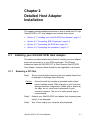
Installing your Ultra160 SCSI Host Adapter
This section provides detailed instructions for installing your host adapter
board and connecting it to your SCSI peripherals. The following
illustrations depict the LSI21003 PCI to Dual Channel Ultra160 SCSI
Host Adapter. However, these illustrations are applicable to all boards.
2.1.1
Selecting a PCI Slot
Step 1.
Ground yourself before removing the host adapter board from
its package to discharge static electricity.
Caution:
Ground yourself by touching a grounded metal surface
before handling boards. Static charges on your body can
damage electronic components. Handle plug-in boards by
the edge; do not touch board components or gold
connector contacts. The use of a static ground strap is
recommended.
Step 2.
Remove your Ultra160 SCSI host adapter from its packing and
verify it is not damaged.
Step 3.
Turn off and unplug your computer and peripherals.
Ultra160 SCSI to PCI Host Adapters
2-1
Step 4.
Remove the cabinet cover on your computer to access the PCI
slots.
Step 5.
Locate the PCI slots on your computer.
Use a 32-bit slot for 32-bit host adapters and a 64-bit slot for
64-bit host adapters. You may insert a 64-bit host adapter into
a 32-bit slot if not 64-bit slots are available. Refer to the user’s
manual supplied with your computer to confirm the location of
the PCI slots.
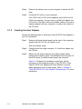
2.1.2
Inserting the Host Adapter
Perform the following steps to install your Ultra160 SCSI Host Adapter in
your PC mainboard.
Step 1.
Remove the blank bracket panel on the back of the computer
aligned with the PCI slot you intend to use.
Save the bracket screw.
Step 2.
Carefully insert the edge connector J1 of the host adapter into
the PCI slot.
Step 3.
Make sure the edge connector is properly aligned before
pressing the board into place. The bracket around connector J3
should fit where the blank bracket panel was removed.
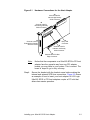
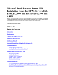
Figure 2.1 illustrates the hardware connections. All the
connectors in this example pertain to the LSI21003. Other
Ultra160 SCSI host adapters will have different connector
labels depending on the board design. Refer to Chapter 3,
“Ultra160 SCSI to PCI Host Adapter Characteristics,” for more
information.
2-2
Detailed Host Adapter Installation
Figure 2.1
Hardware Connections for the Host Adapter
J5
Channel B 68-Pin
Internal High Density
SCSI Connector
J2
Channel A 68-Pin
Internal High Density
SCSI Connector
J3
Channel A 50-Pin
External High Density
SCSI Connector
J6
Busy LED
Connector
J4
Channel A 50-Pin
Internal Low Density
SCSI Connector
J1
Ultra160 SCSI PCI Bus
Edge Connector
Note:
Step 4.
Notice that the components on a Ultra160 SCSI to PCI host
adapter face the opposite way from non-PCI adapter
boards you may have in your system. This is correct. The
board is keyed to go in only one way.
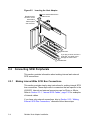
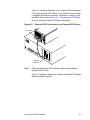
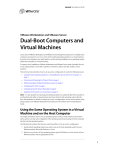
Secure the bracket with the bracket screw before making the
internal and external SCSI bus connections. Figure 2.2 shows
an example of how to insert your host adapter. All LSI Logic
Ultra160 SCSI to PCI host adapters require a PCI slot that
allows bus master operation.
Installing your Ultra160 SCSI Host Adapter
2-3
Figure 2.2
Bracket around
connector J3 fits
where blank
bracket panel
was removed.
Inserting the Host Adapter
Secure the bracket with the
bracket screw.
32-Bit slots
If you plug a 64-bit card into a
32-bit slot, be careful not to
damage the main board.
64-Bit slots
2.2
Connecting SCSI Peripherals
This section provides information about making internal and external
SCSI connections.
2.2.1
Making Internal Wide SCSI Bus Connections
This section provides step-by-step instructions for making internal SCSI
bus connections. These steps refer to connectors that are specific to the
LSI21003. Internal and external connectors can be 50-pin or 68-pin.
Refer to Section 3.3.1, “Internal SCSI Cables,” page 3-10 for examples
of internal cables.
If you have only external connections, skip to Section 2.2.2, “Making
External SCSI Bus Connections,” otherwise follow these steps:
2-4
Detailed Host Adapter Installation
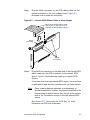
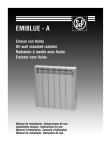
Step 1.
Plug the 68-pin connector on the SCSI ribbon cable into the
internal connector on the host adapter board. Figure 2.3
illustrates how to make this connection.
Figure 2.3
Internal SCSI Ribbon Cable to Host Adapter
68-Pin High Density Ribbon Cable
(See Figure 3.8 and Figure 3.9 for
examples of internal ribbon cables.)
68-Pin
Connector
Internal
Connectors
Step 2.
Plug the 68-pin connector on the other end of the internal SCSI
ribbon cable into the SCSI connector on the internal SCSI
device. Figure 2.4 illustrates the chaining of internal SCSI
devices.
If you have more than one internal SCSI device, you must have
a cable with at least as many connectors as you have devices.
Note:
Daisy chaining devices represent an arrangement of
devices connected in a series. Any signal transmitted to the
devices goes to the first device, from the first to the second,
and so on. Termination occurs on the last internal SCSI
device.
See Section 2.3, “Terminating the SCSI Bus,” for more
information on SCSI bus termination.
Connecting SCSI Peripherals
2-5
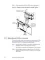
Step 3.
Plug in any additional internal SCSI devices, as required.
Figure 2.4
Multiple Internal SCSI Devices Chained Together
Last Device on Chain–
Termination Enabled
External
Connector
J5 Connector–
Used to connect
multiple internal
SCSI devices
Internal
Connectors
2.2.2
Making External SCSI Bus Connections
This section provides step-by-step instructions for making external SCSI
bus connections. Refer to Section 3.3.2, “External SCSI Cables and
Connectors,” page 3-11 for examples of external cables.
Step 1.
Plug the 50-pin connector on one end of a shielded external
high density cable into the appropriate connector.
This connector is exposed on the back panel of your computer.
Step 2.
2-6
Plug the 50-pin connector on the other end of the shielded
external SCSI cable into the SCSI connector on your external
SCSI device.
Detailed Host Adapter Installation
Figure 2.5 shows an example of an external SCSI connection
to a single external SCSI device. If you have the correct cable,
it matches the external connector. Termination occurs on the
last SCSI device. See Section 2.3, “Terminating the SCSI Bus,”
for more information about SCSI bus termination.
Figure 2.5
External SCSI Connection to an External SCSI Device
Terminator
External
Connector
Step 3.
Chain any additional SCSI devices together with shielded
external SCSI cables.
Figure 2.6 shows an example of multiple external SCSI devices
that are chained together.
Connecting SCSI Peripherals
2-7
Figure 2.6
Multiple External SCSI Devices Chained Together
Last Device
on Chain–
Termination
Enabled
These Devices Do Not
End Chain–
Termination
Disabled
Host Adapter
External Board Connector–
Plugging in automatically
enables termination
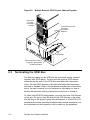
2.3
Terminating the SCSI Bus
The devices making up the SCSI bus are connected serially (chained
together) with SCSI cables. The first and last physical SCSI devices
connected on the ends of the SCSI bus must have their terminators
active. All other SCSI devices on the bus must have their terminators
removed or disabled. Refer to the peripheral manufacturer’s instructions
and to the user’s manual for your computer for information on how to
identify the terminator setting of each device and how to change it.
To utilize Ultra160 SCSI performance, you must only have LVD devices
on the bus. Do not mix any SE devices with LVD devices or the entire
bus will drop to SE speed, limiting bus performance to Ultra SCSI. LVD
peripheral devices are normally terminated with external terminators, but
are sometimes set with jumpers or with a switch on the peripheral.
2-8
Detailed Host Adapter Installation
The Ultra160 SCSI host adapters automatically control SCSI bus
termination for various bus configurations.
In one case, you may disable termination by using BIOS software control
to change the BIOS termination from Automatic to Off.
In another case where jumpers are provided on the board, you would
locate the shunts on the board for autotermination override. Termination
can be disabled by placing a manual shunt over the post. When the
shunt is off, the terminator is active. When the shunt is on the post, the
terminator is disabled. Figure 2.7 illustrates how the shunt controls
autotermination.
Figure 2.7
Autotermination Shunt
Autotermination enabled (no jumper installed)
Termination disabled (jumper installed)
2.3.1
Internal and External SCSI Terminations
If you are making internal SCSI device connections to your host adapter,
you must terminate the last internal device on the SCSI bus. If you are
making external SCSI device connections to your host adapter, you must
terminate the last external device on the SCSI bus. You must disable the
termination on all other devices. Termination on your host adapter is
automatically enabled in this case.
2.3.2
Setting SCSI IDs
You must set each SCSI device and the host adapter to a separate SCSI
ID. The IDs are 0 through 7 for an 8-bit bus and 0 through 15 for a 16-bit
bus. SCSI ID 7 is the preset host adapter setting, giving it the highest
priority on the SCSI bus.
If you plan to boot your computer from a hard disk drive on the SCSI
bus, that drive should have SCSI ID 0, or the lowest SCSI ID on the bus.
Normally, you do not change the host adapter SCSI ID setting. If you
wish to do so, refer to the PCI Storage Device Management System
SDMS 4.0 User’s Guide, which explains how to set your host adapter ID
using the SCSI BIOS Configuration Utility.
Terminating the SCSI Bus
2-9
The peripheral device SCSI IDs are usually set with jumpers or with a
switch on the peripheral. Refer to the peripheral manufacturer’s
instructions and to the user’s manual for your computer to determine the
ID of each device and how to change it. No duplication of SCSI IDs is
allowed on a SCSI bus. To set your SCSI IDs, follow these steps:
Step 1.
Determine the SCSI ID of each device on the SCSI bus.
Step 2.
Make any necessary changes to the SCSI IDs and record the
IDs for future reference. Correct any duplications at this time.
Table 2.1 provides a place to keep this record.
Table 2.1
SCSI ID
SCSI ID Record
SCSI Device Channel A
SCSI Device Channel B
Ultra160 SCSI to PCI
Host Adapter
Ultra160 SCSI to PCI
Host Adapter
15
14
13
12
11
10
9
8
7
6
5
4
3
2
1
0
2-10
Detailed Host Adapter Installation
2.4
Completing the Installation
Before replacing the cover on your computer, review this installation
procedure check list. This can save you effort later.
Verify Installation Procedures
Done
Host adapter connection in PCI bus slot secure (level)
Internal SCSI bus connections secure (pin-1 continuity)
External SCSI bus connections secure
Proper SCSI bus termination established
Unique SCSI IDs set and recorded for each device
Step 1.
Replace the cabinet cover on your computer.
Step 2.
Plug in all power cords, turn on the peripherals, and then turn
on your computer.
Step 3.
Wait for your computer to boot up.
Step 4.
Refer to the LSI Logic PCI Storage Device Management
System SDMS 4.0 User’s Guide (or the guide for the software
you will use) to load the driver software for your particular
operating system and to change the configuration of your host
adapter, if needed.
Completing the Installation
2-11
2-12
Detailed Host Adapter Installation
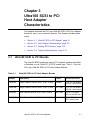
Chapter 3
Ultra160 SCSI to PCI
Host Adapter
Characteristics
This chapter describes the LSI Logic Ultra160 SCSI to PCI Host Adapter
boards for use in your computer systems. This chapter includes these
topics:
3.1
•
Section 3.1, “Ultra160 SCSI to PCI Boards,” page 3-1
•
Section 3.2, “Host Adapter Characteristics,” page 3-2
•
Section 3.3, “Cabling SCSI Devices,” page 3-10
•
Section 3.4, “Technical Specifications,” page 3-13
Ultra160 SCSI to PCI Boards
The Ultra160 SCSI boards are used in PCI computer systems with either
a Standard or Low Profile PCI (LPPCI) bracket type. Table 3.1 lists the
LSI Logic Ultra160 SCSI to PCI Host Adapter Boards.
Table 3.1
Ultra160 SCSI to PCI Host Adapter Boards
Adapter
Description
Bracket
Board Dimensions
LSI20160
Single Channel Ultra160 SCSI, 32-bit, 33 MHz
Standard
4.721 x 2.536 inches
119.913 x 64.414 mm
LSI20160L
Single Channel Ultra160 SCSI, 32-bit, 33 MHz
Low Profile
4.721 x 2.536 inches
119.913 x 64.414 mm
LSI22903
Dual Channel Ultra160 SCSI, 64-bit, 33 MHz
Low Profile
6.60 x 2.53 inches
167.64 x 64.262 mm
LSI22915A
Dual Channel Ultra160 SCSI, 64-bit, 66 MHz
Standard
8.5 x 3.80 inches
215.9 x 96.52 mm
Ultra160 SCSI to PCI Host Adapters
3-1
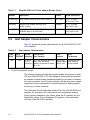
Table 3.1
Adapter
Ultra160 SCSI to PCI Host Adapter Boards (Cont.)
Bracket
Board Dimensions
ITI6200U3LP Dual Channel Ultra160 SCSI Low Profile PCI
Low Profile
6.6 x 2.5 inches
167.64 x 63.5 mm
LSI21003
Legacy Dual Channel Ultra160 SCSI,
32-bit, 33 MHz
Standard
7.5 x 2.5 inches
190.5 x 63.5 mm
LSI21040
Legacy Dual Channel Ultra160 SCSI,
64-bit/33 MHz or 32-bit/33 MHz
Standard
8.5 x 3.80 inches
215.9 x 96.52 mm
3.2
Description
Host Adapter Characteristics
Table 3.2 shows the general characteristics for all Ultra160 SCSI to PCI
Host Adapters.
Table 3.2
Flash
ROM1
Yes
Host Adapter Characteristics
Serial
LVD/SE
Ultra160 SCSI
EEPROM2 Signaling Data Transfers
Yes
16-bit SE
or LVD
interfaces
Up to 160 Mbytes/s as well as
Fast, Ultra, and Ultra2
speeds; Synchronous offsets
up to 62.
SCSI
Features
SCSI
Termination
Plug n Play
TERMPWR with
Scatter/Gather auto resetting
Activity LED
circuit breaker
1. For BIOS (boot ROM)
2. For BIOS configuration storage
The following sections provide the pertinent details and features of each
LSI Logic Ultra160 SCSI to PCI host adapters. Along with these features,
an example of each board’s mechanical drawing is provided to illustrate
the main connectors, the LSI Logic controller, and the termination speed
supported by these connections. Footnotes below the drawing specify
the function of each connector.
The Subsystem ID and Subsystem Vendor ID for the Ultra160 SCSI host
adapters are provided in the notes below each mechanical drawing.
During system initialization, the system loads the ID numbers into the
Subsystem Vendor ID and Subsystem ID registers of the embedded
LSI Logic Ultra160 SCSI controllers.
3-2
Ultra160 SCSI to PCI Host Adapter Characteristics
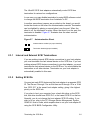
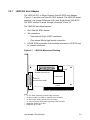
3.2.1
LSI20160 Host Adapter
The LSI20160 PCI to Single Channel Ultra160 SCSI Host Adapter
(Figure 3.1) provides one Ultra160 SCSI channel. The LSI20160 board
supports Low Voltage Differential (LVD) and Single-Ended (SE) SCSI.
The SCSI interface is made through connectors J2 and J4.
The LSI20160 has these features:
•
One Ultra160 SCSI channel
•
Two connectors
•
–
One external 68-pin VHDCI connection
–
One internal 68-pin high density connection
LVD/SE SCSI termination for the external connection; LVD SCSI only
for internal connection
Figure 3.1
LSI20160 Mechanical Drawing
J4
Channel A
Ultra160 SCSI LVD only
J2
Channel AI
Ultra160 SCSI LVD/SE
J3 LED
LSI53C1000
J1T-PCI
Note:
• J1: PCI 32-bit universal type board edge connector.
• J2: 68-pin VHDCI connector for external SCSI connection.
• J4: 68-pin high density internal SCSI connection.
• J3: 4-pin low density unshrouded right-angle LED connector.
• Subsystem Vendor ID is 1000.
• Subsystem ID is 1060.
Host Adapter Characteristics
3-3
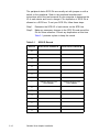
3.2.2
LSI20160L Host Adapter
The LSI20160L PCI to Single Channel Ultra160 SCSI Low Profile PCI
Host Adapter (Figure 3.2) provides one Ultra160 SCSI channel. The
LSI20160L board supports Low Voltage Differential (LVD) and SingleEnded (SE) SCSI. The LSI20160L board is the LPPCI board with a low
profile bracket. The SCSI interface is made through connectors J2 and
J4.
The LSI20160L has these features:
•
One Ultra160 SCSI channel
•
Two connectors
•
–
One external 68-pin VHDCI connection
–
One internal 68-pin high density connection
LVD/SE termination
Figure 3.2
LSI20160L Mechanical Drawing
J4
Channel A
Ultra160 SCSI LVD only
J2
Channel A
Ultra160 SCSI LVD/SE
J3 LED
LSI53C1000
J1T - PCI
Note:
• J1: PCI 32-bit, universal type board edge connector.
• J2: 68-pin VHDCI connector for external SCSI connection.
• J4: 68-pin high density internal SCSI connection.
• J3: 4-pin low density unshrouded right-angle LED connector.
• Subsystem Vendor ID is 1000.
• Subsystem ID is 1060.
3-4
Ultra160 SCSI to PCI Host Adapter Characteristics
3.2.3
LSI22903 Host Adapter
The LSI Logic LSI22903 PCI to Dual Channel Ultra160 SCSI Low Profile
PCI Host Adapter (Figure 3.3) provides two independent Ultra160 SCSI
channels. The LSI22903 board is a LPPCI board with a low profile
bracket. The SCSI interface is made through connector J2 for channel A
and J4 for channel B.
The LSI22903 has these features:
Figure 3.3
•
Two independent Ultra160 SCSI channels
•
Two connectors
–
One external 68-pin VHDCI connection
–
One internal 68-pin high density connection
•
LVD/SE termination for external Channel A
•
LVD termination for internal Channel B
LSI22903 Mechanical Drawing
J4
Channel B
Ultra160 SCSI LVD only
J3 LED
LSI53C1010
J2
Channel A
Ultra160 SCSI LVD/SE
J1T - PCI
Note:
• J1: PCI 64-bit, universal type board edge connector.
• J2: 68-pin very high density external connector for channel A.
• J4: 68-pin high density internal connector for channel B.
• J3: 4-pin low density unshrouded right-angle LED connector.
• Subsystem Vendor ID is 1000.
• Subsystem ID is 1020.
Host Adapter Characteristics
3-5
3.2.4
LSI22915A Host Adapter
The LSI22915A PCI to Dual Channel Ultra160 SCSI Host Adapter
(Figure 3.4) provides two separate Ultra160 SCSI channels. Both
channel A and channel B of the LSI22915A support LVD and SE as a
SCSI solution for your computer. The SCSI interface is made through
connector J1 or J3 for channel A and J4 or J7 for channel B.
The LSI22915A has these features:
•
Two separate Ultra160 SCSI channels
•
Four connectors
•
Figure 3.4
–
Two external 68-pin VHDCI connections
–
Two internal 68-pin high density connections
LVD/SE termination for both channels
LSI22915A Mechanical Drawing
B
A
HDR1
J3 Channel A
Ultra160 SCSI LVD/SE
J4 Channel B
Ultra160 SCSI LVD/SE
J7
Channel B
Ultra160 SCSI LVD/SE
HDR2
Activity
LED
HDR5
HDR3
J1
Channel A
Ultra160 SCSI LVD/SE
LSI53C1010
J6 - PCI
Note:
• J6: PCI 64-bit, universal type board edge connector.
• J3 and J4: 68-pin high density shielded right-angle internal connectors.
• J1 and J7: 68-pin VHDCI shielded right-angle external connector.
• HDR1 and HDR2: Remote Activity Indicator Connection for channel A and channel B.
• HDR3 and HDR5: Disable Termination for channel A and channel B
• Subsystem Vendor ID is 1000; Subsystem ID is 1010.
• Refer to Figure 3.5 (ITI6200U3LP) for LVD Status Indicator information.
3-6
Ultra160 SCSI to PCI Host Adapter Characteristics
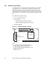
3.2.5
ITI6200U3LP Host Adapter
The ITI6200U3LP (Figure 3.5) is an Ultra160 SCSI Low Profile PCI Host
Adapter that provides high performance (160 Mbytes/s per channel).
The ITI6200U3LP has these features:
•
•
Figure 3.5
Three connectors
–
Two external 68-pin VHDCI connections
–
One internal 68-pin high density connection
LVD/SE termination for both channels
ITI6200U3LP Mechanical Drawing
Channel A LED
HDR5
J4 Channel B
Ultra160 SCSI LVD/SE only
HDR3
J1
Channel A and Channel B (Side by Side)
Ultra160 SCSI LVD/SE
LSI53C1010
Channel B LED
J6 - PCI
Note:
• J6: PCI 64-bit, universal type board edge connector.
• J1: 68-pin VHDCI shielded right-angle external channel A and channel B
• J4: 68-pin high density internal connector for channel B.
• HDR3: Disable termination when installed for channel A.
• HDR5: Disable termination when installed for channel B.
• Subsystem Vendor ID is 13E9.
• Subsystem ID is 1300.
The LVD status indicators for the LSI22915A and ITI6200U3LP are:
LVD Status Indicator
o
o
o
Act. (Activity)
On = Bus Busy
Term. (Termination) On = Terminating
LVD (Mode)
On = LVD; Off = SE; Blink = (error)
Host Adapter Characteristics
3-7
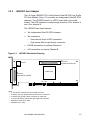
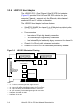
3.2.6
LSI21003 Host Adapter
The LSI21003 PCI to Dual Channel Ultra160 SCSI host adapter
(Figure 3.6) provides 16-bit LVD and SE SCSI solutions for your
computer. Channel A supports only the SE mode, while channel B
supports LVD and SE modes of operation.
The LSI21003 host adapter has these features:
Figure 3.6
•
Ultra SCSI Wide SE for channel A to 40 Mbytes/s per data transfer;
Ultra160 SCSI for channel B to 160 Mbytes/s per data transfer
•
Four connectors
–
One external 50-pin high density connection
–
Two internal 68-pin high density connections
–
One internal 50-pin low density legacy connection for channel A
•
Channel A is SE only with autosense termination
•
Channel B is SE or LVD with termination permanently enabled
LSI21003 Mechanical Drawing
J2 Channel A - Ultra SCSI Wide SE
J6 LED J5 Channel B - Ultra160 SCSI LVD/SE
J4 Channel A - Ultra SCSI Wide SE
A Terminators
B Terminators
J3
Channel A
Ultra SCSI
Wide SE
LSI53C1010
J1 - PCI
Note:
• J1: PCI 32-bit, universal type board edge connector.
• J2 and J5: 68-pin high density shielded latching right-angle internal connectors.
• J3: 50-pin high density shielded right-angle external connector.
• J4: 50-pin low density shrouded vertical internal connector.
• J6: 4-pin low density unshrouded right-angle LED connector.
• Subsystem Vendor ID is 1000.
• Subsystem ID is 1050.
3-8
Ultra160 SCSI to PCI Host Adapter Characteristics
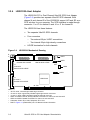
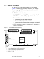
3.2.7
LSI21040 Host Adapter
The LSI21040 PCI to Dual Channel Ultra160 SCSI host adapter
(Figure 3.7) provides 16-bit LVD and SE solutions for your computer.
Channel A supports LVD/SE modes of operation, while channel B
supports only the SE mode.
The LSI21040 board has these features:
•
Ultra160 SCSI for channel A to 160 Mbytes/s per data transfer; Ultra
SCSI SE for channel B to 40 Mbytes/s per data transfer
•
Four connectors
•
Figure 3.7
–
One external 68-pin high density connection
–
Two internal 68-pin high density connections
–
One internal 50-pin low density legacy connections for channel B
LVD/SE termination on channel A automatically; SE termination on
channel B automatically
LSI21040 Mechanical Drawing
J2
J4
J6-LED
Channel A - Ultra160 SCSI LVD/SE
J5
J2 Channel B - Ultra Wide SCSI SE
J5 Channel B - Ultra, Fast, and SCSI-1 SE
J3
Channel A
Ultra160 SCSI LVD/SE
LSI53C1010
J1T - PCI
Note:
• J1: PCI 64-bit, universal type board edge connector.
• J2 and J4: 68-pin high density shielded latching right-angle internal connectors.
• J3: 68-pin high density shielded right-angle external connector.
• J5: 50-pin low density shrouded vertical internal connector.
• J6: 4-pin low density unshrouded right-angle LED connector.
• Subsystem Vendor ID is 1000.
• Subsystem ID is 1040.
Host Adapter Characteristics
3-9
3.3
Cabling SCSI Devices
The cable provided in your host adapter kit is matched to the host
adapter board and its operation. The Ultra160 SCSI cable also has
built-in multimode (LVD/SE) termination because most Ultra160 hard disk
drives are not made with on-board LVD termination.
Table 3.3 lists standard cable specifications.
Table 3.3
Cable Specifications
Maximum Bus Length, Meters1
STA Term
SE
LVD
Maximum Devices
Ultra SCSI
1.5
see note2
8/4
1.5/3
see note2
8/4
Ultra2 SCSI
see note3
12
8
Wide Ultra2 SCSI
see note3
12
16
Ultra160
see note3
12
16
Wide Ultra SCSI
1. This parameter may be exceeded in point-to-point and engineered
applications.
2. LVD was not defined in the original SCSI standards for this speed. If all
devices on the bus support LVD, then 12-meter operation is possible at
this speed. However, if any device on the bus is SE only, then the entire
bus switches to SE mode, and the distances in the SE column apply.
3. SE and High Voltage Differential (HVD) are not defined at greater than
Ultra speeds.
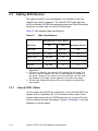
3.3.1
Internal SCSI Cables
You can make internal SCSI bus connections to your Ultra160 SCSI host
adapter with an unshielded, 68- or 50-conductor ribbon cable. Some
internal cables come with an LVD/SE terminator on one end. This end
must be farthest from the host adapter. Figures 3.8 through 3.10 provide
examples of internal cables.
3-10
Ultra160 SCSI to PCI Host Adapter Characteristics
Figure 3.8
SCSI Cable – 68-Pin High Density with Termination
Terminator
Figure 3.9
SCSI Cable – 68-Pin High Density without Termination
Figure 3.10 SCSI Cable – 50-Pin Low Density
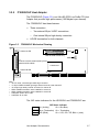
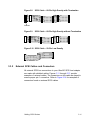
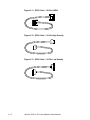
3.3.2
External SCSI Cables and Connectors
All external SCSI bus connections to your Ultra160 SCSI host adapter
are made with shielded cables. Figures 3.11 through 3.13 provide
examples of external cables. The connectors on this cable are keyed to
ensure proper pin-1 connection. Refer to Figure 3.14 for examples of
connectors found on external SCSI cables.
Cabling SCSI Devices
3-11
Figure 3.11 SCSI Cable – 68-Pin VHDCI
Figure 3.12 SCSI Cable – 50-Pin High Density
Figure 3.13 SCSI Cable – 50-Pin Low Density
3-12
Ultra160 SCSI to PCI Host Adapter Characteristics
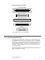
Figure 3.14 External Connectors
Centronics 50-Pin Male
High Density 50-Pin Male
High Density 68-Pin Male
Very High Density Centronics 68-Pin Male
DB25 Male
Note: The DB25 Connector is not a SCSI Standard.
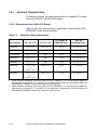
3.4
Technical Specifications
The design and implementation of the LSI Logic Ultra160 SCSI to PCI
host adapter boards minimize electromagnetic emissions, susceptibility
to radio frequency energy, and the effects of electrostatic discharge. The
board carries the CE mark, C-Tick mark, FCC Self-Certification log,
Canadian Compliance Statement, and meets the requirements of FCC
and CISPR Class B.
Ultra160 SCSI boards have specific electrical, thermal, atmospheric, and
safety characteristics in common.
Technical Specifications
3-13
3.4.1
Electrical Characteristics
This section provides the power requirements for standard PCI boards
and Low Profile PCI Ultra160 SCSI boards.
3.0.0.1 Standard and Low Profile PCI Boards
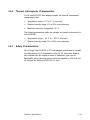
Table 3.4 lists the maximum power requirements, which include SCSI
TERMPWR, under normal operation.
Table 3.4
Maximum Power Requirements
PCI +5.0 V DC
PCI +3.3 V DC
PCI PRSNT1#/
PRSNT2# Power
Over the
Operating Range
LSI201601
1.3 A, ±5 %
1.00 A, ±5 %
7.5 W
0 ˚C to 55 ˚C
LSI22915A1
3.0 A, ±5 %
N/A
15 W
0 ˚C to 55 ˚C
ITI6200U3LP1
3.0 A, ±5 %
N/A
15 W
0 ˚C to 55 ˚C
LSI210401
3.0 A, ±5 %
N/A
7.5 W
0 ˚C to 55 ˚C
LSI21003
1.5 A, ±5 %
N/A
15 W
0 ˚C to 55 ˚C
LSI20160L2
1.3 A, ±5 %
or
0.40 A, ±5 %
1.00 A, ±5 %
7.5 W
0 ˚C to 55 ˚C
LSI229032
1.3 A, ±5 %
or
0.40 A, ±5 %
0.80 A, ±5 %
7.5 W
0 ˚C to 55 ˚C
Host Adapter
1. Under abnormal conditions, such as a short on SCSI TERMPWR, +5 V current may be higher. At
temperatures of at least 25 ˚C, a current of 4 A is sustained no longer than 30 seconds before the
self-resetting TERMPWR short circuit protection device opens.
2. Under abnormal conditions, such as a short on SCSI TERMPWR, +5 V current may be higher. At
temperatures of at least 25 ˚C, a current of 8 A is sustained no longer than 0.5 seconds before the
self-resetting TERMPWR short circuit protection device opens.
3-14
Ultra160 SCSI to PCI Host Adapter Characteristics
3.4.2
Thermal, Atmospheric Characteristics
For all Ultra160 SCSI host adapter boards, the thermal, atmospheric
characteristics are:
•
Temperature range: 0 ˚C to 55 ˚C (dry bulb)
•
Relative humidity range: 5% to 90% noncondensing
•
Maximum dew point temperature: 32 ˚C
The following parameters define the storage and transit environment for
the LSI20160L:
3.4.3
•
Temperature range: − 45 ˚C to + 105 ˚C (dry bulb)
•
Relative humidity range: 5% to 90% noncondensing
Safety Characteristics
All LSI Logic Ultra160 SCSI to PCI host adapter boards meet or exceed
the requirements of UL flammability rating 94 V0. Each bare board is
also marked with the supplier’s name or trademark, type, and UL
flammability rating. Because these boards are installed in a PCI bus slot,
all voltages are below the SELV 42.4 V limit.
Technical Specifications
3-15
3-16
Ultra160 SCSI to PCI Host Adapter Characteristics
Appendix A
Glossary of Terms and
Abbreviations
Active
Termination
The electrical connection required at each end of the SCSI bus,
composed of active voltage regulation and a set of termination resistors.
Ultra, Ultra2, and Ultra160 SCSI require active termination.
AIP
Asynchronous Information Protection (AIP) provides error checking for
asynchronous, nondata phases of the SCSI bus.
BIOS
Basic Input/Output System. Software that provides basic read/write
capability. Usually kept as firmware (ROM based). The system BIOS on
the mainboard of a computer is used to boot and control the system. The
SCSI BIOS on your host adapter acts as an extension of the system
BIOS.
Configuration
Refers to the way a computer is setup; the combined hardware
components (computer, monitor, keyboard, and peripheral devices) that
make up a computer system; or the software settings that allow the
hardware components to communicate with each other.
CRC
Cyclic Redundancy Check (CRC) is an error detection code used in
Ultra160 SCSI. Four bytes are transferred with the data to increase the
reliability of data transfers. CRC is used on the Double Transition (DT)
Data-In and DT Data-Out phases.
DMA Bus
Master
A feature that allows a peripheral to control the flow of data to and from
system memory by blocks, as opposed to PIO (Programmed I/O) where
the processor is in control and the flow is by byte.
Device Driver
A program that allows a microprocessor (through the operating system)
to direct the operation of a peripheral device.
Differential SCSI
A hardware configuration for connecting SCSI devices. It uses a pair of
lines for each signal transfer (as opposed to Single-Ended SCSI which
references each SCSI signal to a common ground).
Ultra160 SCSI to PCI Host Adapters
A-1
Domain
Validation
Domain Validation is a software procedure in which a host queries a
device to determine its ability to communicate at the negotiated Ultra160
data rate.
Double
Transition
Clocking
In Double Transition (DT) Clocking, data is sampled on both the asserting
and deasserting edge of the REQ/ACK signal. DT clocking may only be
implemented on an LVD SCSI bus.
EEPROM
Electronically Erasable Programmable Read Only Memory. A memory
chip typically used to store configuration information. See NVRAM.
External SCSI
Device
A SCSI device installed outside the computer cabinet. These devices are
connected in a continuous chain using specific types of shielded cables.
Host
The computer system in which a SCSI host adapter is installed. It uses
the SCSI host adapter to transfer information to and from devices
attached to the SCSI bus.
Host Adapter
A circuit board or integrated circuit that provides a SCSI bus connection
to the computer system.
Internal SCSI
Device
A SCSI device installed inside the computer cabinet. These devices are
connected in a continuous chain using an unshielded ribbon cable.
Local Bus
A way to connect peripherals directly to computer memory. It bypasses
the slower ISA and EISA buses. PCI is a local bus standard.
Mainboard
A large circuit board that holds RAM, ROM, the microprocessor, custom
integrated circuits, and other components that make a computer work. It
also has expansion slots for host adapters and other expansion boards.
Main Memory
The part of a computer’s memory which is directly accessible by the CPU
(usually synonymous with RAM).
NVRAM
NonVolatile Random Access Memory. Actually an EEPROM
(Electronically Erasable Read Only Memory chip) used to store
configuration information. See EEPROM.
PCI
Peripheral Component Interconnect. A local bus specification that allows
connection of peripherals directly to computer memory. It bypasses the
slower ISA and EISA buses.
A-2
Glossary of Terms and Abbreviations
Peripheral
Devices
A piece of hardware (such as a video monitor, disk drive, printer, or
CD-ROM) used with a computer and under the computer’s control. SCSI
peripherals are controlled through a SCSI host adapter.
Pin-1
Orientation
The alignment of pin 1 on a SCSI cable connector and the pin-1 position
on the SCSI connector into which it is inserted. External SCSI cables are
always keyed to insure proper alignment, but internal SCSI ribbon cables
sometimes are not keyed.
RAM
Random Access Memory. The computer’s primary working memory in
which program instructions and data are stored and are accessible to the
CPU. Information can be written to and read from RAM. The contents of
RAM are lost when the computer is turned off.
ROM
Read Only Memory. Memory from which information can be read but not
changed. The contents of ROM are not erased when the computer is
turned off.
SCAM
SCSI Configured AutoMatically. A method to automatically allocate SCSI
IDs using software when SCAM compliant SCSI devices are attached.
SCSI
Small Computer System Interface. A specification for a high-performance
peripheral bus and command set. The original standard is referred to as
SCSI-1.
SCSI Bus
A host adapter and one or more SCSI peripherals connected by cables
in a linear chain configuration. The host adapter may exist anywhere on
the chain, allowing connection of both internal and external SCSI
devices. A system may have more than one SCSI bus by using multiple
host adapters.
SCSI Device
Any device that conforms to the SCSI standard and is attached to the
SCSI bus by a SCSI cable. This includes SCSI host adapters and SCSI
peripherals.
SCSI ID
A way to uniquely identify each SCSI device on the SCSI bus. Each
SCSI bus has eight available SCSI IDs numbered 0 through 7 (or 0
through 15 for Wide SCSI). The host adapter usually gets the highest ID
(7 or 15) giving it priority to control the bus.
SDMS
Storage Device Management System. An LSI Logic software product that
manages SCSI system I/O.
A-3
Single-Ended
SCSI
A hardware specification for connecting SCSI devices. It references each
SCSI signal to a common ground. This is the most common method (as
opposed to differential SCSI which uses a separate ground for each
signal).
Synchronous
Data Transfer
One of the ways data is transferred over the SCSI bus. Transfers are
clocked with fixed frequency pulses. This is faster than asynchronous
data transfer. Synchronous data transfers are negotiated between the
SCSI host adapter and each SCSI device.
Ultra SCSI
A standard for SCSI data transfers. It allows a transfer rate of up to
20 Mbytes/s over an 8-bit SCSI bus and up to 40 Mbytes/s over a 16-bit
SCSI bus.
Ultra2 SCSI
A standard for SCSI data transfers. It allows a transfer rate of up to
40 Mbytes/s over an 8-bit SCSI bus, and up to 80 Mbytes/s over a
16-bit SCSI bus.
Ultra160 SCSI
A standard for SCSI data transfers. It allows a transfer rate of up to
160 Mbytes/s over a 16-bit SCSI bus.
VHDCI
Very High Density Cable Interconnect.
A-4
Glossary of Terms and Abbreviations
Index
B
H
BIOS software control
disabling termination 2-9
brackets 1-1, 2-2
bus configurations 2-9
host adapter
inserting 2-2–2-4
installation check list 2-11
ITI6200U3LP 3-7
LSI20160 3-3
LSI20160L 3-4
LSI21003 3-8
LSI21040 3-9
LSI22903 3-5
LSI22915A 3-6
host adapters
maximum power requirements 3-14
supporting Ultra160 SCSI 1-1
C
cables
specifications 3-10
characteristics
electrical 3-14
safety 3-15
thermal, atmospheric 3-15
check list for installation of host adapter 2-11
completing the installation 2-11
connecting the SCSI peripherals 2-4
connections
making external SCSI bus 2-6
making internal SCSI bus 2-4
D
daisy chaining devices 2-5
detailed installation procedure 2-1–2-11
devices
SE and LVD 2-8
I
internal SCSI bus connections
additional internal devices 2-5
making 2-4
Internal SCSI Terminations 2-9
J
jumpers 2-9
L
LSI Logic controllers 1-1
LVD peripheral devices 2-8
E
electrical characteristics 3-14
external SCSI bus connections
external chaining 2-8
making 2-6
F
F6 key
pressing during installation process 1-4
M
manual shunt
placing over post 2-9
maximum power requirements 3-14
miniport driver
sym_u3.sys 1-4
Ultra160 SCSI to PCI Host Adapters
IX-1
P
U
PCI slot
selecting 2-1
peripheral devices 2-10
preset host adapter setting
SCSI ID 2-9
UL flammability rating 3-15
Ultra160 3-1
Ultra160 SCSI to PCI
controllers 1-1
Ultra160 SCSI to PCI host adapters
board descriptions 3-1
subsystem/subsystem vendor IDs 3-2
Q
quick driver installation procedure 1-4
quick host adapter installation 1-3
S
safety characteristics 3-15
SCSI bus
terminating 2-8
termination
using software control
2-9
SCSI cables
external 3-11–3-12
internal 3-10–3-11
SCSI connectors
external 3-13
SCSI devices
cabling 3-10
SCSI IDs
setting 2-9
SCSI peripherals
connecting 2-8
SCSI termination
internal and external 2-9
SDMS CD-ROM 1-2
service packs
for Windows NT 4.0 1-4
specifications
cables 3-10
static ground strap 2-1
T
technical specifications 3-13–3-15
thermal, atmospheric characteristics 3-15
IX-2
Index
W
Windows NT 4.0
service packs 1-4
Windows NT/WIndows 2000
miniport driver 1-4
Windows NT/Windows 2000
installing operating system and driver 1-4
obtaining device drivers 1-2
Customer Feedback
We would appreciate your feedback on this document. Please copy the
following page, add your comments, and fax it to us at the number
shown.
If appropriate, please also fax copies of any marked-up pages from this
document.
Important:
Please include your name, phone number, fax number, and
company address so that we may contact you directly for
clarification or additional information.
Thank you for your help in improving the quality of our documents.
Ultra160 SCSI to PCI Host Adapters
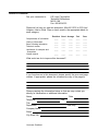
Reader’s Comments
Fax your comments to:
LSI Logic Corporation
Technical Publications
M/S E-198
Fax: 408.433.4333
Please tell us how you rate this document: Ultra160 SCSI to PCI Host
Adapters User’s Guide. Place a check mark in the appropriate blank for
each category.
Excellent Good Average
Completeness of information
Clarity of information
Ease of finding information
Technical content
Usefulness of examples and
illustrations
Overall manual
Fair
Poor
____
____
____
____
____
____
____
____
____
____
____
____
____
____
____
____
____
____
____
____
____
____
____
____
____
____
____
____
____
____
What could we do to improve this document?
If you found errors in this document, please specify the error and page
number. If appropriate, please fax a marked-up copy of the page(s).
Please complete the information below so that we may contact you
directly for clarification or additional information.
Name
Telephone
Title
Department
Company Name
Street
City, State, Zip
Customer Feedback
Date
Fax
Mail Stop
You can find a current list of our U.S. distributors, international distributors, and sales
offices and design resource centers on our web site at
http://www.lsilogic.com/contacts/na_salesoffices.html