1
Installation and
Reference Guide
HP J3233B
HP J3234B
HP J3272A
HP J3247A
HP J3248A
HP AdvanceStack 100Base-T Hubs
and Switch Modules
© Copyright 1998 Hewlett-Packard Company
All Rights Reserved
Reproduction, adaptation, or translation without prior written permission is prohibited,
except as allowed under the copyright laws.
Publication Number
5967-2285
Edition 1
April 1998
Applicable Product
HP J3233B AdvanceStack 100Base-T Hub-12TXM
HP J3234B AdvanceStack 100Base-T Hub-12TX
HP J3272A AdvanceStack 100Base-T Hub-24TX
HP J3247A AdvanceStack 10/100TX Switch Port Module
HP J3248A AdvanceStack 100FX Switch Port Module
Disclaimer
The information contained in this document is subject to change without notice.
HEWLETT-PACKARD COMPANY MAKES NO WARRANTY OF ANY KIND
WITH REGARD TO THIS MATERIAL, INCLUDING, BUT NOT LIMITED TO,
THE IMPLIED WARRANTIES OF MERCHANTABILITY AND FITNESS FOR A
PARTICULAR PURPOSE. Hewlett-Packard shall not be liable for errors contained
herein or for incidental or consequential damages in connection with the furnishing,
performance, or use of this material.
Hewlett-Packard assumes no responsibility for the use or reliability of its software on
equipment that is not furnished by Hewlett-Packard.
Warranty
See the warranty booklet included with the product.
A copy of the specific warranty terms applicable to your Hewlett-Packard product and
replacement parts can be obtained from your HP sales and service office or HP
authorized reseller.
Hewlett-Packard Company
8000 Foothills Boulevard, m/s 5551
Roseville, California 95747-5551
http://www.hp.com/go/network_city
Package Contents
Carefully unpack the contents of the package and verify them
against the checklist given below. This checklist applies to both
the HP AdvanceStack 100Base-T Hub-12TXM, the HP
AdvanceStack 100Base-T Hub-12TX, and the HP AdvanceStack
100Base-T Hub-24TX.
Package Checklist
æ HP J3233B AdvanceStack 100Base-T Hub-12TXM
)DVW(WKHUQHW6WDFNDEOH+XEZLWK%DVH7;3RUWVLQFOXGLQJ6103
0DQDJHPHQW6XSSRUW
or
HP J3234B AdvanceStack 100Base-T Hub-12TX
)DVW(WKHUQHW6WDFNDEOH+XEZLWK%DVH7;3RUWV
or
HP J3272A AdvanceStack 100Base-T Hub-24TX
)DVW(WKHUQHW6WDFNDEOH+XEZLWK%DVH7;3RUWV
with optional
HP J3247A 10/100TX Switch Port Module
)DVW(WKHUQHW%DVH7;6ZLWFK3RUW0RGXOHZLWK
0',;SRUWDQG0',FDVFDGHSRUW
or
HP J3248A 100FX Switch Port Module
)DVW(WKHUQHW%DVH);6ZLWFK3RUW0RGXOHZLWK6&W\SH
5;DQG7;SRUWV
æ One rack mount kit
æ Four rubber foot pads
Package Contents
i
HP 100Base-T Hubs Installation and Reference Guide
æ Power cord, one of the following:
Australia/New Zealand (8120-6810)
Denmark (8120-6814)
Europe (8120-6811)
Japan (8120-6798)
Switzerland (8120-6815)
United States/Canada (8120-6812)
United Kingdom (8120-6809)
æ One 0.2 meter Stacking Cable. Used for connecting hubs
together into a stack via the Stacking Ports. Provides both
data and management channels.
æ One serial cable. Used for VT-100 console interface
configuration and for out-of-band and SLIP management.
æ Installation manual
æ Warranty booklet
Please inform your reseller immediately should there be any
wrong, missing, or damaged parts.
If possible, retain the carton, including the original packing
materials. Use them again to repack the unit in case there is a
need to return it for repair.
ii
Quick Installation
Quick Installation
Hewlett-Packard’s Hub-12TX/Hub-12TXM models each contain
12 Fast Ethernet 100Base-TX, RJ-45 (MDI-X) ports, one MDI
cascade port, and one Expansion Slot for an optional connection
using 10/100TX and 100FX Switch Port Module. The Hub-24TX
contains 24 Fast Ethernet 100Base-TX, RJ-45 (MDI-X) ports,
and one MDI cascade port.
The design built into the front display panel and configuration
options provides a friendly interface that simplifies installation
and network troubleshooting. If you are already familiar with
basic network operations, you should be able to install this hub
as described below:
1. Unpack the HP 100Base-T unit.
2. Find a location close to the network devices you need to
connect, and within easy reach of an electrical outlet.
3. Mount the hub on a desktop or any other flat surface. If you
are installing multiple hubs, you can stack them on top of
each other (after attaching the foot pads), or install them in a
standard EIA 19-inch rack. Note that these hubs do not
support wall mounting. See Chapter 2 for more details.
4. Connect any devices that use a standard 100Base-TX RJ-45
connector to the RJ-45 (MDI-X) station ports (for example,
a workstation or server). Use 100W Category 5 unshielded
twisted-pair (UTP) or 100W shielded twisted-pair (STP)
cable. Also be sure that the length of any twisted-pair
connection does not exceed 100 meters. (Refer to Chapter
2 for a more detailed description of calculating the maximum
cable length permitted between two end nodes.)
5. If you are stacking multiple hubs, connect the Stacking
Cable between the Stacking Ports (Out and In), found on the
rear panel of the hub, on adjacent hubs. Run a simple chain
starting at the Out port on the first managed hub (Hub-
Quick Installation
iii
HP 100Base-T Hubs Installation and Reference Guide
12TXM), and ending at the In port on the last hub. No more
than five hubs can be connected via the Stacking Cable.
Note: When connecting hubs with the Stacking Cable, they are all
part of the same collision domain by default. Also if a Hub-12TXM
is present, all of the hubs are managed by it.
6. Isolate any hubs you want to remove from the stack’s
collision domain.
For the Hub-12TXM, use the Hub Configuration screen in
the VT-100 console interface. Select the System
Configuration option from the main menu and press Enter.
Select the Hub Configuration option from the System
Configuration menu and press Enter. Then select a hub from
the Hub Selection menu and press Enter. The system
displays the Hub Configuration screen. In the Isolate field,
press Enter and then use <Ctrl+N> to change the setting to
Yes. Then press Enter to save the new value. See Chapter 4
for more details on using the VT-100 console interface.
For the Hub-12TX/Hub-24TX, enter the command “i” in
the Status section of the Main Configuration menu, then
press “y” to confirm the change of isolation status. Press
Enter to save the new value.
7. Connect isolated hubs to the stack’s main collision domain.
You may do this in one of two ways.
If you have an optional 10/100TX Switch Port Module,
you can connect an isolated hub to other hubs in the stack,
while still segmenting the collision domains, using one of the
following two methods:
• Install the Switch Port Module in the isolated hub in
the stack. Run a connection from the 100Base-TX port
on the optional 10/100TX Switch Port Module on this
hub to any station port on a non-isolated hub in the stack.
Make sure you connect to an MDI port on the hub if you
are running off the MDI-X port on the module, or vice
versa.
iv
Quick Installation
HP 100Base-T Hubs Installation and Reference Guide
• Install the Switch Port Module on a non-isolated hub
in the stack and run a connection from the Switch Port
Module to a station port on the isolated hub.
When connecting a hub to the 10/100TX Switch Port
Module, the maximum cable length is 100 meters. This is a
bridged connection and keeps the collision domain on the
isolated hub separate from the main collision domain of the
other hubs in the stack.
If you do not have an available Switch Port Module, the
isolated hub can be connected to the stack collision domain
by the following method.
• Run straight-through, twisted-pair cable from the hub’s
MDI port to an MDI-X port on a switch or router. Make
sure the switch or router has RJ-45 ports; if not, attach a
standard MAU for the AUI port to achieve the
connection.
8. Connect the overall stack to the extended network by
connecting a hub to an internetwork device.
• Run straight-through, twisted-pair cable from the hub’s
MDI port to an MDI-X port on a switch, bridge or router.
Make sure the router has RJ-45 ports; if not, attach a
standard MAU for the AUI port to achieve the
connection.
Notes: 1. When using the 12MDI/24MDI port, remember that port
12MDI-X/24MDI-X cannot be used.
2. If you have hubs that are isolated in the stack, in order to
connect the stack collision domain to the network, use the
station port of a hub that is NOT isolated.
9. Verify network communications.
• you have made all the necessary connections
• you can access any connected resources
• the hub’s indicators are functioning properly
• the power cords for all connected devices are connected
to a valid power source
Quick Installation
v
HP 100Base-T Hubs Installation and Reference Guide
Special Considerations to Note
The following are special considerations to note:
• When connecting an end node to the Switch Port on the
Switch Port Module, the maximum cable length is 100
meters for twisted-pair cable, and two kilometers for fiber.
Refer to Chapter 2 for a more detailed description of the
maximum cable length permitted.
• For integrating legacy networks, the 10/100TX Switch Port
Module provides for connection via either 100Base-TX or
10Base-T. A 10/100TX Switch Port Module uses autosensing to set the transmission speed at 10 or 100 Mbit/s, even
if the target device does not support auto-negotiation (for
transmission mode, full duplex or half duplex).
• The Switch Port Modules support both half-duplex and fullduplex communications. However, for this hub to correctly
set the transmission mode, the attached device must also
support auto-negotiation. If auto-negotiation fails, the
transmission mode defaults to half duplex. If this setting is
not suitable, then the transmission mode must be manually
configured using the Exp Slot Configuration screen in the
VT-100 console interface (see Chapter 4).
• To reactivate auto-negotiation on the 10/100TX Switch Port
Module, just unplug a connection from the Switch Port on
the hub and plug it in again. Remember that full-duplex
mode can only be used for switched (not shared) connections
on its own collision domain. When connecting to a shared
collision domain (i.e., another hub) set the transmission mode
for half duplex.
• Depending on your network configuration, you may attain
better performance by making a direct connection from the
HP 100Base-T Hub to an interconnection device rather than
using a Switch Port Module. Making a connection from a
Switch Port Module may introduce slightly more delay.
vi
Quick Installation
HP 100Base-T Hubs Installation and Reference Guide
• Make sure you connect the stack (main collision domain) to
the extended network. If you have hubs in the stack that are
isolated, be certain to use a station port of a hub that is NOT
isolated in order to connect the stack collision domain to the
extended network.
• If you are inserting a Hub-24TX into a stack of Hub12TX/Hub-12TXMs that has been running an existing
firmware revision, make sure to download the latest version
of firmware so that your devices will be compatible and can
connect with one another with no problems. See the section
on the Xmodem Download VT-100 Interface console screen
in chapter 4 for more information about firmware
downloads.
• A network management station on the extended network
should be able to access a Hub-12TXM in the stack in order
to manage all the devices in the stack’s collision domain.
Make sure that the Hub-12TXM is NOT isolated, it should
be in the stack’s main collision domain and connected to the
extended network.
Quick Installation
vii
About this Guide
This guide is designed for the experienced network installer.
It describes how to install and operate the HP AdvanceStack
100Base-T system. After reading this manual, you should be
able to use the front display panel and configure options to
manage all your network connections.
This manual covers the following topics:
Chapter 1
- Product Overview
Brief description of Fast Ethernet, followed by a description of
this hub and a summary of its important features and
specifications.
Chapter 2
- Installing the System
Installing a HP 100Base-T hub and making basic network
connections. Also includes details on performing tasks using
significant components on the hub including ports and indicators.
Chapter 3
- Setting up Network Connections
Shows sample network configurations for a local area network.
Chapter 4
- Configuring the System
Describes how to manage the system via the VT-100 console
interface.
Chapter 5
- Hardware Reference
Detailed description of indicator panel and ports.
Appendices - Troubleshooting, pin assignments, and product specifications.
About this Guide
ix
Contents
Chapter 1: Product Overview
1-1
Introduction to Fast Ethernet
Brief Description of the HP 100Base-T Hubs
Hub-12TX
Hub-12TXM
Hub-24TX
Switch Port Modules
Network Management Software
Distinguishing Features of the HP 100Base-T Hubs
Features of the HP 100Base-T Hubs
Features of HP AdvanceStack Switch Port Modules
Data Switching with the Switch Port Modules
Switching Technology
Configuration Options for the Switch Port Modules
Switching Methods
1-1
1-1
1-3
1-3
1-4
1-4
1-4
1-6
1-7
1-9
1-10
1-10
1-10
1-11
Chapter 2: Installing the System
2-1
Pre-Installation Requirements
Hardware Installation
Stacking Hubs without a Rack
Mounting Hubs in a Rack
Connecting the Hub System
Making a Connection via an MDI-X Hub Port
Connecting the Stacking Cable
Making a Connection via the MDI Cascade Port
Connecting to a Switch Port Module
Powering on the Hub
Diagnostic Tests
Hot Swap
Configuring a Manageable Stack
Installing an SNMP Backup Agent
Verifying Port Status
Verifying System Operation
2-1
2-2
2-2
2-3
2-4
2-4
2-5
2-6
2-6
2-12
2-12
2-13
2-13
2-13
2-14
2-14
Contents
xi
HP 100Base-T Hubs Installation and Reference Guide
Chapter 3: Setting up Network Connections 3-1
xii
Special Architecture Used for the HP 100Base-T Hubs
Isolation Architecture
Stacking Cable Management Channel
Hub ID Setting
Using Management Agents
SNMP Backup Agent
Backup Links Function
Security Features
Intrusion Protection
Sample Network Configurations
Connecting Hubs to the Stack
Isolating Specific Hub Connections
Isolating Multiple Hubs
Extending the Network with Alternate Connections
Linking the Stack to a Management Station
Interconnecting Isolated Collision Domains
Connecting Remote Stacks
Connecting to the Extended Network
3-1
3-1
3-2
3-2
3-3
3-3
3-4
3-4
3-4
3-5
3-5
3-6
3-7
3-8
3-9
3-10
3-11
3-12
Chapter 4: Configuring the System
4-1
Making the Connections Required for System Configuration
Direct Connection
Network Connection
Local Network Telnet Connection
Local Network Connection
Remote Connection
Configuring the Hub-12TXM Site
Configuring the Remote Site
Remote Configuration Methods
Configuring Your System
Using the VT-100 Console Interface
System Configuration for the Hub-24TX
System Configuration for the Hub-12TX
Configuring the Switch Port Module
4-1
4-2
4-2
4-2
4-3
4-3
4-3
4-4
4-4
4-5
4-7
4-7
4-8
4-10
Contents
HP 100Base-T Hubs Installation and Reference Guide
System Configuration for the Hub-12TXM and Stack
Displaying System Information
System Configuration
Changing the Network Configuration
Configuring the SNMP Agent
Configuring SNMP Communities
Configuring IP Trap Receivers
Configuring IPX Trap Receivers
Configuring Hub Parameters
Hub Configuration
Hub ID Configuration
Configuring Port Parameters
Configuring Hub Ports
Configuring the Switch Port Module
Port Intrusion Control
Defining Backup Ports
System Statistics
Stack Statistics
Hub Statistics
Port Statistics
Statistics for Hub Ports
Statistics for Switch Port Module
Downloading System Software
Downloading System Software via a TFTP Server
Xmodem Download
Console Security
Connectivity Test
Rebooting the Hub
Exiting the VT-100 Console Interface
4-11
4-12
4-13
4-14
4-16
4-17
4-18
4-19
4-20
4-21
4-22
4-23
4-23
4-24
4-26
4-27
4-29
4-30
4-31
4-33
4-33
4-35
4-36
4-36
4-38
4-39
4-41
4-45
4-45
Chapter 5: Hardware Reference
5-1
Indicator Panel
Power
Exp Slot
Managed
Management Mode Indicators
Hub ID
Console
5-2
5-3
5-3
5-4
5-4
5-5
5-5
Contents
xiii
HP 100Base-T Hubs Installation and Reference Guide
xiv
Isolated
Utilization %
Collision %
Port Status Indicators
Link/Traffic
Partition/Disable
Diagnostic Test Indicators
Network Connections
Station Ports
Cascade Port
Console Port
Rear Panel Components
Power Socket
Stacking Ports
In
Out
5-5
5-6
5-6
5-7
5-8
5-8
5-10
5-11
5-11
5-11
5-12
5-13
5-13
5-14
5-14
5-14
Appendix A: Troubleshooting
A-1
Diagnosing Hub Indicators
System Diagnostics
Power and Cooling Problems
Installation
Transmission Mode
Cabling
LAN Adapters
Physical Configuration
System Integrity
A-1
A-2
A-2
A-2
A-2
A-3
A-3
A-4
A-4
Appendix B: Pin Assignments
B-1
RJ-45 Port
DB9 Serial Port Pin Description
Hub’s 9-Pin Serial Port to PC’s 9-Pin COM Port
Hub’s 9-Pin Serial Port to PC’s 25-Pin DTE Port
Hub’s 9-Pin Serial Port to Modem’s 25-Pin DCE Port
B-1
B-2
B-3
B-4
B-5
Contents
HP 100Base-T Hubs Installation and Reference Guide
Appendix C: Modem Configuration
C-1
Appendix D: Product Specifications
D-1
Product Specifications
D-1
Appendix E: Regulatory Statements
E-1
Mounting Precautions
Power Precautions
Safety Information
Grounding
Servicing
Informations concernant la sécurité
Hinweise zur Sicherheit
Considerazioni sulla sicurezza
Consideraciones sobre seguridad
Safety Information (Japanese)
Safety Information (Chinese)
Regulatory Statements
FCC Class A Statement (for U.S.A. Only)
European Community
Canada
Australia
Declaration of Conformity
E-1
E-2
E-3
E-3
E-3
E-4
E-5
E-6
E-7
E-8
E-9
E-10
E-10
E-11
E-11
E-11
E-12
Appendix F: Product Support Services
F-1
World Wide Web
HP FIRST Fax Retrieval Service
Additional HP Support Services
F-1
F-1
F-2
Glossary
Index
Contents
xv
HP 100Base-T Hubs Installation and Reference Guide
List of Figures
Figure 2.1
Figure 2.2
Figure 3.1
Figure 3.2
Stacking Hubs without a Rack
Mounting Hubs Using a Mounting Rack
Attaching All Hubs to the Stack Collision Domain
Linking Part of the Stack to the Stack Collision
Domain with Straight-through, Category 5
Twisted-pair Cable
Figure 3.3 Stacking Isolated Hubs with Straight-through,
Category 5 Twisted-pair Cable
Figure 3.4 Linking Stacked Hubs to Standalone Hubs via
Stacking Cable and Cascaded Connections with
Straight-through, Category 5 Twisted-pair Cable
Figure 3.5 Linking Stacked Hubs to a Network Management
Station
Figure 3.6 Linking Isolated Collision Domains in a Stacked
System
Figure 3.7 Connecting Remote Stacks using Switch Port
Modules
Figure 3.8 Connecting to the Extended Network
Figure 4.1 Main Configuration Menu (Hub-24TX only)
Figure 4.2 Main Configuration Menu (Hub-12TX only)
Figure 4.3 Configuration Menu for Switch Port Module (Hub12TX only)
Figure 4.4 Main Configuration Menu
Figure 4.5 System Information Menu
Figure 4.6 System Configuration Menu
Figure 4.7 Network Configuration Menu
Figure 4.8 SNMP Configuration Menu
Figure 4.9 SNMP Communities Menu
Figure 4.10 IP Trap Receivers Menu
Figure 4.11 IPX Trap Receivers Menu
Figure 4.12 Hub Configuration: Hub Selection Menu
Figure 4.13 Hub Configuration Menu
Figure 4.14 Hub ID Configuration Menu
Figure 4.15 Port Configuration: Port Selection Menu
Figure 4.16 Port Configuration Menu
Figure 4.17 Exp Slot Port Configuration Menu
xvi
Contents
2-2
2-3
3-5
3-6
3-7
3-8
3-9
3-10
3-11
3-12
4-8
4-9
4-10
4-11
4-12
4-13
4-14
4-16
4-17
4-18
4-19
4-20
4-21
4-22
4-23
4-24
4-25
HP 100Base-T Hubs Installation and Reference Guide
Figure 4.18 Port Intrusion Control: Hub Selection Menu
Figure 4.19 Port Intrusion Control Menu
Figure 4.20 Backup Links Menu
Figure 4.21 Statistics Menu
Figure 4.22 Stack Statistics Menu
Figure 4.23 Hub Statistics: Hub Selection Menu
Figure 4.24 Hub Statistics Window
Figure 4.25 Port Statistics: Port Selection Menu
Figure 4.26 Port Statistics Menu
Figure 4.27 Exp Slot Port Statistics Menu
Figure 4.28 Download Menu
Figure 4.29 TFTP Download Menu
Figure 4.30 Xmodem Download Menu
Figure 4.31 Console Security Menu
Figure 4.32 Connectivity Test Menu
Figure 4.33 IP Ping Test Menu
Figure 4.34 IPX Ping Test Menu
Figure 4.35 Link Test Menu
Figure 4.36 Screen Messages for Rebooting the Hub
Figure 5.1 Front Panel of the Hub-12TXM
Figure 5.2 Front Panel of the Hub-24TX
Figure 5.3 Indicators
Figure 5.4 HP J3247A for 100Base-TX
Figure 5.5 HP J3248A for 100Base-FX
Figure 5.6 Rear Panel
Figure B.1 RJ-45 Connector (on the Hub Side)
Figure B.2 DB9 Serial Port (on the Hub Side)
4-26
4-26
4-28
4-29
4-30
4-31
4-32
4-33
4-34
4-35
4-36
4-37
4-39
4-40
4-41
4-42
4-43
4-44
4-45
5-1
5-2
5-2
5-3
5-3
5-13
B-1
B-2
List of Tables
Table 2.1 Maximum Fiber Lengths for Basic Topology Models
Table 2.2 Calculating the Power Budget for Fiber Optic
Devices
Table 2.3 Power Budget for Common Fiber Optic Devices
Table 2.4 Checking Key LED Indicators
Table 2.5 Maximum Cable Length
Table 4.1 Configuration Options in Main Menu (Hub-24TX
only)
2-8
Contents
xvii
2-9
2-9
2-14
2-15
4-8
HP 100Base-T Hubs Installation and Reference Guide
Table 4.2 Configuration Options in Main Menu (Hub-12TX
only)
Table 4.3 Configuration Options for Switch Port Module
(Hub-12TX only)
Table 4.4 Main Configuration Menu
Table 4.5 System Information Menu
Table 4.6 System Configuration Menu
Table 4.7 Network Configuration Menu
Table 4.8 SNMP Configuration Menu
Table 4.9 SNMP Communities Menu
Table 4.10 IP Trap Receivers Menu
Table 4.11 IPX Trap Receivers Menu
Table 4.12 Hub Configuration Menu
Table 4.13 Port Configuration Menu
Table 4.14 Exp Slot Port Configuration Menu
Table 4.15 Port Intrusion Control Menu
Table 4.16 Backup Links Menu
Table 4.17 Statistics Menu
Table 4.18 Stack Statistics Menu
Table 4.19 Hub Statistics Window
Table 4.20 Port Statistics Menu
Table 4.21 Exp Slot Port Statistics Menu
Table 4.22 Download Menu
Table 4.23 TFTP Download Menu
Table 4.24 Xmodem Download Menu
Table 4.25 Console Security Menu
Table 4.26 IP Ping Test Menu
Table 4.27 IPX Ping Test Menu
Table 4.28 Link Test Menu
Table 5.1 Power Indicator
Table 5.2 Switch Port Module Indicator
Table 5.3 Switch Port Module Indicators
Table 5.4 Managed Indicator
Table 5.5 Management Mode Indicators
Table 5.6 Console Indicator
Table 5.7 Isolated Indicator
Table 5.8 Utilization Indicators
Table 5.9 Collision Indicators
Table 5.10 Link/Traffic Indicators
xviii
Contents
4-9
4-10
4-12
4-13
4-14
4-15
4-16
4-17
4-18
4-19
4-22
4-24
4-25
4-27
4-28
4-29
4-30
4-32
4-34
4-35
4-36
4-37
4-39
4-40
4-42
4-43
4-44
5-3
5-3
5-4
5-4
5-4
5-5
5-5
5-6
5-6
5-8
HP 100Base-T Hubs Installation and Reference Guide
Table 5.11 Partition/Disable Indicators
Table 5.12 Diagnostic Results
Table 5.13 Diagnostic Indicators
Table B.1 RJ-45 Pin Assignments
Table B.2 DB9 Port Pin Assignments
Table B.3 RS-232-C “Null Modem” Cable Connection from
Hub’s 9-Pin Serial Port to PC’s 9-Pin COM Port
Table B.4 Minimum Cable Connection from Hub’s 9-Pin
Serial Port to PC’s 9-Pin COM Port
Table B.5 Full-Pin Connection from Hub’s 9-Pin Serial Port to
PC’s 25-Pin DTE Port
Table B.6 Three-Pin Connection from Hub’s 9-Pin Serial Port
to PC’s 25-Pin DTE Port
Table B.7 Hub’s 9-Pin Serial Port to Modem’s 25-Pin DCE Port
Pin Assignments
Contents
5-8
5-10
5-10
B-1
B-2
B-3
B-3
B-4
B-4
B-5
xix
Chapter 1:
Product Overview
Introduction to Fast Ethernet
Standard 10 Mbit/s Ethernet has served well for past
generations of 286 and 386 machines performing simple file
transfers. However, with the inevitable growth in corporate
network size and the introduction of fully-functional 32-bit PC
architectures, and operating systems running complex
applications, 10 Mbit/s Ethernet has become a serious
bottleneck.
Among the recent flood of choices for upgrading media
bandwidth, 100 Mbit/s Fast Ethernet has the benefits of low
cost, compatibility with existing Ethernet applications, and the
fact that it can run on top of an installed base of twisted-pair
cabling.
Moreover, by using a dual-speed switch (10 or 100 Mbit/s),
Fast Ethernet can be easily integrated into an existing 10 Mbit/s
Ethernet environment with no need for protocol translation or
changes to network software. It also includes specifications for
a media-independent interface (MII), which permits a switched
connection to any of the 100Base-T sublayers; i.e., 100Base-TX
(10Base-T), or 100Base-T4.
Brief Description of the HP 100Base-T Hubs
The HP 100Base-T Hubs provide a powerful and innovative
LAN network enhancement and management product series.
All hubs support a Fast Ethernet isolation architecture that
enhances traffic management and network bandwidth
utilization. This system offers the network manager a wide
range of flexible configuration options, allowing you to
increase your network’s bandwidth tenfold or more. In
Product Overview
1-1
HP 100Base-T Hubs Installation and Reference Guide
addition, the entire installation can be monitored via SNMP
protocol through any network management station.
Moreover, the HP 100Base-T Hubs provide advanced network
security features including “Intrusion Protection” which ensures
that only designated workstations are able to transmit packets
onto the network. Management access via the out-of-band
serial port or in-band via Telnet is also password protected.
The basic components of this network system include:
Full Connectivity
• Provides 12 or 24 RJ-45 (MDI-X) 100Base-TX Fast Ethernet
(shielded) hub ports for connecting devices to the network
using straight-through shielded or unshielded twisted-pair
cable (100W Cat 5 UTP or STP)
• 1 RJ-45 (MDI) cascade port for connection to a switch,
eliminating the need for crossover cables
• 1 Expansion Slot for optional Switch Port Modules which
provide a connection to 10/100Base-TX or 100Base-FX via
the Switch Port
• An architecture that supports stack isolation to enhance
network traffic management and bandwidth utilization
• Stacking Ports for connecting to multiple hubs in a Hub-12TX
/Hub-24TX stack via a Stacking Cable
• On-board management via the RS-232 Console Port
connected directly to a terminal, or to a local or remote
computer (that provides a standard RS-232 port) running a
VT-100 console
1-2
Product Overview
HP 100Base-T Hubs Installation and Reference Guide
Hub-12TX
)DVW(WKHUQHW6WDFNDEOH+XEZLWK%DVH7;3RUWV
The Hub-12TX conforms to the IEEE 802.3u hub specification.
It also collects port statistics and records events for system
administration. Basic configuration is provided by the VT-100
console interface.
This hub can be used in a standalone configuration to form a
simple LAN networking two to 12 computers using the RJ-45
hub ports.
Moreover, when stacked with other hubs through the Stacking
Ports and connected to an SNMP management device (e.g., the
Hub-12TXM), it can be monitored and controlled through inband or out-of-band channels.
Two to five hubs can be stacked and connected together with
the Stacking Cable, each additional hub correspondingly
increasing the stack’s collision domain. Just one Hub-12TXM
placed in a stack is sufficient to manage all other hubs.
Hub-12TXM
)DVW(WKHUQHW6WDFNDEOH+XEZLWK%DVH7;3RUWVLQFOXGLQJ6103
0DQDJHPHQW6XSSRUW
This model conforms to both the IEEE 802.3u hub specification
and the Simple Network Management Protocol (SNMP). It not
only functions as a 12-port Fast Ethernet hub, but also provides
an SNMP-based network management agent for monitoring and
controlling various network components. It can monitor up to
five hubs connected to the same stack (including itself) through
the Stacking Port connection. This hub provides SNMP
management for the connected stack via various Management
Information Bases (MIBs), including MIB II, several hub MIBs,
and a private MIB.
Product Overview
1-3
HP 100Base-T Hubs Installation and Reference Guide
Hub-24TX
)DVW(WKHUQHW6WDFNDEOH+XEZLWK%DVH7;3RUWV
The Hub-24TX conforms to the IEEE 802.3u hub specification.
It functions in the same way as the Hub-12TX, except that it
does not have a slot to accept the Switch Port Modules.
This hub can be used in a standalone configuration to form a
simple LAN networking two to 24 computers using the RJ-45
hub ports. It can also be stacked with other hubs through the
Stacking Ports and connected to an SNMP management device
(e.g., the Hub-12TXM). Similarly, it can be monitored and
controlled through in-band or out-of-band channels.
Switch Port Modules
%DVH7;+3-$$GYDQFH6WDFN7;6ZLWFK3RUW0RGXOH
Provides one RJ-45 MDI-X port and one RJ-45 MDI port, of
which only one can be used at a time. Transmission speed is
automatically set to 10 or 100 Mbit/s via auto-sensing, and the
mode is set to half or full duplex via auto-negotiation.
%DVH);+3-$$GYDQFH6WDFN);6ZLWFK3RUW0RGXOH
Provides one SC type connector for 100Base-FX connection.
Transmission speed is always 100 Mbit/s and transmission
mode is manually set to half or full duplex using the VT-100
console interface.
Network Management Software
+3$GYDQFH6WDFN$VVLVWDQW
This Windows and Unix-based network management software
discovers the HP 100Base-T hubs and displays device symbols
in a Topology View, a network map that shows the placement
of the hub in relation to other devices on the same stack,
segment, or subnetwork.
1-4
Product Overview
HP 100Base-T Hubs Installation and Reference Guide
HP AdvanceStack Assistant should be installed on the network
management station designated to manage the HP 100Base-T
stack. Note that you need a Hub-12TXM in your collision
domain to use HP AdvanceStack Assistant via the console port.
The workstation may communicate with the stack via a network
connection or from a remote site (using SLIP over TCP/IP). If
isolated architecture is used, the network management station
should be connected to the same segment as the SNMP
management agent (i.e., Hub-12TXM).
The minimal configuration for a PC network management
station includes a 66MHz Intel 486 PC platform with 24
Mbytes of RAM and 30 Mbytes available space on the hard
drive, a VGA display, and Windows 95 or Windows NT 3.51.
Product Overview
1-5
HP 100Base-T Hubs Installation and Reference Guide
Distinguishing Features of the HP 100Base-T Hubs
The HP 100Base-T Hubs provide the following key features:
• Stack isolation architecture allowing the network to be split
into multiple collision domains
• Supports fault-tolerant configuration by allowing port
backup links and agent backup
• Supports management functions via SNMP
• Supports VT-100 console management
• Discovery and mapping features using HP AdvanceStack
Assistant
• The VT-100 console agent supports nearly any network
environment by providing management options via SNMP/IP
and SNMP/IPX
• Provides security features including port intrusion protection,
as well as password protection for out-of-band access or
Telnet network access
• Hot swap function allows you to add/remove hubs in the stack
without disrupting communications
• SNMP backup agents
1-6
Product Overview
HP 100Base-T Hubs Installation and Reference Guide
Features of the HP 100Base-T Hubs
Features of the HP AdvanceStack 100Base-T Hubs are:
General Features -
Basic Hub Functions
• Transmits all incoming frames to the other hubs in the stack
collision domain using the Stacking Cable
• Automatically partitions and reconnects devices which
experience excessive collisions
• Jabber lockup protection provided by disabling any port that
receives 64 Kbytes of continuous data, and re-enabling the
port after the condition improves
Outstanding Performance
• Total bandwidth of up to 500 Mbit/s
• The Stacking Cable contains a high-speed management
channel
• Manages up to five hubs using the Stacking Cable. The
Hub-12TXM can manage up to four other hubs via the
management channel in the Stacking Cable
Management Features -
Extensive Management
Capabilities
• An extensive indicator panel for reporting network activity,
unit configuration and facilitating problem diagnosis
• Menu-driven system configuration can be accessed via a
local or remote terminal connection to the hub’s serial port,
using either a standard VT-100 terminal or a PC running a
VT-100 console interface
• The Hub-12TXM with SNMP support for discovery and
mapping using the HP AdvanceStack Assistant network
management program
• Provides one serial 9-pin RS-232 port for local and remote
out-of-band network management
Product Overview
1-7
HP 100Base-T Hubs Installation and Reference Guide
• BOOTP support for dynamic address assignment
• Flash ROM on board the Hub-12TXM for easily updating the
SNMP agent, using either standard firmware updating
software or HP’s Download Manager program, an agent
downloading Windows program
• Firmware update supported for the Hub-12TXM via out-of-
band Xmodem file transfer through the serial port, or TFTP
file transfer over the network
Installation Features -
Easy Installation
• Flexible installation for desktop or rack (standard 19” size)
• Plug-and-play design
• Self-diagnostics
• Automatic ID assignment for auto-configuration
Standards and Architecture Compatibility -
Complete Standards
Conformance
• Adapts to universal wide range voltage power
(i.e., 100-240 VAC, 50-60 Hz)
• Conforms to IEEE 802.3u Class I repeater specification
and 100Base-TX standard (i.e., 100 Mbit/s Fast Ethernet)
• Optional Switch Port Modules conform to relevant IEEE
specifications and standards for respective media types
• Supports MIB II, Ethernet Repeater MIB, Ethernet MIB, and
private MIB
• Conforms to Simple Network Management Protocol
(SNMP)
1-8
Product Overview
HP 100Base-T Hubs Installation and Reference Guide
Features of HP AdvanceStack Switch Port Modules
Features of the HP AdvanceStack 10/100TX and 100FX Switch
Port Modules are:
Networking Flexibility
(via Switch Port Modules)
• One Expansion Slot supports optional slide-in Switch Port
Modules for connection to 10Base-T, 100Base-TX or
100Base-FX (on a separate collision domain)
• Transparent bridging (between stack and external device) via
optional Switch Port Modules
• Uses adaptive cut-through switching (which dynamically
changes among standard cut-through, fragment-free cut-through,
and store-and-forward depending on the CRC error rate)
• Two transmission modes: full duplex or half duplex
• Auto-detects transmission speed at 100 Mbit/s or 10 Mbit/s
(10/100TX Switch Port Module only)
• Auto-negotiates transmission mode for full duplex and half
duplex (if same feature is supported by attached device);
otherwise can be manually configured (10/100TX Switch
Port Module only)
• Automatically learns MAC addresses to build a routing
information database
• Automatically filters local traffic
• Transparent to all higher level protocols
Product Overview
1-9
HP 100Base-T Hubs Installation and Reference Guide
Data Switching with the Switch Port Modules
Switching Technology
The Switch Port Modules that plug into the Expansion Slot on
the front panel of the AdvanceStack Hub-12TX/Hub-12TXM
use advanced switching techniques to provide a high-speed
network backbone. Each Switch Port Module acts as a two-port
Ethernet switch that segments the stack from the extended
network.
The module scans the destination address from the packet
header, searches the routing table provided for the incoming
port and forwards the packet only if required, often before fully
received. A learning function stores the address and corresponding segment identifier of each incoming and outgoing
packet in a routing table. This information is subsequently
used to filter packets whose destination address is on the same
segment as the source address. This confines network traffic to
its respective domain, reducing the overall load on the network.
Configuration Options for the Switch Port Modules
The 10/100Base-TX and
100Base-FX media both support
full-duplex operation.
The Switch Port Modules can be connected to a subnetwork, or
directly to a server or key workstation, or to an isolated hub in
the stack. In addition to partitioning an overloaded network,
they provide a connection between legacy 10Base-T networks
and the newer generation 100Base-TX, and can be configured
to operate in either full-duplex or half-duplex data transfer
mode to support the interconnection requirements of other
high-speed devices.
These modules perform cut-through switching, which can direct
a packet according to the destination address scanned from the
packet header. This technique results in packet transmission at
near-zero latency.
1-10
Product Overview
HP 100Base-T Hubs Installation and Reference Guide
As a device functioning on the media access control (MAC)
layer, the Switch Port Modules are protocol independent, and
therefore compatible with TCP/IP, NetWare, DECnet and XNS
protocols. They can provide a connection between
conventional 10Base-T and high-speed 100Base-TX networks;
or can serve as a bridge in a 100Base-TX or 100Base-FX
environment. Moreover, where traditional 100Base-TX
networks restrict the maximum distance between end-nodes to
205 meters, these modules break down this barrier. By
breaking your network into smaller and more manageable
segments, each linked to the larger network with a Switch Port
Module, the maximum distance for communications between
end-nodes is unlimited (depending on the specific timing
requirements of your network applications).
Switching Methods
Traditional bridges and routers use a switching method called
store-and-forward in which the entire frame must be received
before the device can perform a table look-up for the
destination node and forward the packet to the corresponding
port. As a result, each packet experiences a significant delay.
It may be necessary to use store-and-forward when a lot of data
errors are occurring over the network, or when connecting to
very slow devices. Compared to this “safe” mode of operation,
cut-through switching significantly reduces packet
transmission delay by picking the destination address out of the
header as soon as it is received, and directing the frame to the
appropriate segment (or the backbone) long before the full
packet has been received. The remaining technique, employed
to improve data reliability, is called fragment-free cutthrough. It uses a more conservative approach to cut-through
that waits until the collision window has elapsed (i.e., the first
full 64 bytes have been received) before processing the packet.
This prevents runts from being passed along, effectively
cleaning up the data stream.
Product Overview
1-11
HP 100Base-T Hubs Installation and Reference Guide
Although cut-though switching is recommended as the fastest
method for most applications, the other methods mentioned
above are also supported by the Switch Port Modules to
guarantee flawless performance. To ensure that you can
manage any kind of network load, the modules use adaptive
cut-through switching based on an algorithm. This method
dynamically changes the way it handles data based on the
current error rate. These switching alternatives start at standard
cut-through for a clean data environment, change to fragmentfree cut-through for a moderate error rate, and then progress to
store-and-forward for a highly contentious environment. By
using this method, the Switch Port Modules deliver the best
networking performance under any environment.
Moreover, in addition to using adaptive switching to optimize
throughput, these modules also support back pressure to
eliminate frame loss after the switch port’s buffers (that store
incoming packets) fill by “blocking” unwanted traffic from
being passed onto a segment.
1-12
Product Overview
Chapter 2:
Installing the System
This chapter describes how to install the HP AdvanceStack
100Base-T Hubs and establish network connections. You may
install this hub on any level surface (e.g., a table or shelf) or in
a standard equipment rack. However, please take note of the
following minimum site requirements before you begin.
Note: The HP 100Base-T Hubs do not support wall mounting.
Pre-Installation Requirements
Before you start actual hardware installation, make sure you
can provide the right operating environment, including power
requirements, sufficient physical space, and proximity to other
network devices that are to be connected. Verify the following
installation requirements:
• Power requirements: 100 to 240 VAC (± 10%) at 50 to 60
Hz. The hub’s power supply automatically adjusts to the
input voltage level.
• The hub should be located in a cool dry place, with at least
10 cm. of space at the front and back for ventilation.
• Place the hub out of direct sunlight, and away from heat
sources or areas with a high amount of electromagnetic
interference.
• If you intend to mount the hub in a rack, make sure you have
the mounting screws, brackets, bolts and nuts, and the
correct tools.
• Be sure the network cables and connectors needed for
installation are available.
Installing the System
2-1
HP 100Base-T Hubs Installation and Reference Guide
Hardware Installation
F
This hub is suitable for desktop or rack-mount installation. A
good location is at the center of all the devices you want to link,
close to the extended network, and near a power outlet.
These hubs can be stacked with other hubs using a mounting rack or
directly on top of one another. Refer to the sections on Stacking
Hubs without a Rack or Mounting Hubs in a Rack for a description of
these methods.
If you don’t want to stack the hub with other hubs now, or if you plan
to use the hub in a standalone configuration, skip this step and
proceed to Connecting the Hub System.
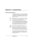
Stacking Hubs without a Rack
The hub can be stacked anywhere there is a sufficiently large
flat space, such as on a table or desktop.
1. Stick the self-adhesive rubber foot pads (that come with this
package) on each of the 4 hollow spaces located on the
bottom of the first hub.
2. Place the first hub on a firm and flat surface in the area
where you want the stack to be installed.
3. Attach the rubber feet on each hub before stacking them.
They cushion the hub against shock/vibrations and provide
space between each hub for ventilation.
You do not need the rack
mount kit if you are not
mounting the hub in a rack.
Keep the mounting brackets and
screws, however, for possible
future use.
Figure 2.1 Stacking Hubs without a Rack
2-2
Installing the System
HP 100Base-T Hubs Installation and Reference Guide
Mounting Hubs in a Rack
Please comply with the following instructions to ensure that
your hub is securely mounted in the rack.
1. Use a standard EIA 19-inch rack.
2. Use a Phillips (i.e., cross-head) screwdriver to attach the
brackets to the sides of the hub.
3. Position the hub in the rack by lining up the holes in the
brackets with the appropriate holes on the rack, and then use
the supplied screws to mount the hub in the rack.
Figure 2.2 Mounting Hubs Using a Mounting Rack
Installing the System
2-3
HP 100Base-T Hubs Installation and Reference Guide
Connecting the Hub System
Remember to label all your
connections at both ends of the
cable to facilitate troubleshooting
or future changes to network
configuration.
The HP 100Base-T Hubs have 12 or 24 RJ-45 shielded ports
(i.e., 100Base-TX) that support connections to 100 Mbit/s Fast
Ethernet. Ports 1 - 12/24 (MDI-X) allow you to connect to
devices such as a workstation or server. While Port 12/Port 24
(MDI) lets you easily cascade to a compatible switch or router
(i.e., connecting from MDI to MDI-X ports on either device).
The Hub-12TX/Hub-12TXM also provides an Expansion Slot
for plugging in optional Switch Port Modules. These modules
support a single connection to 100Base-TX (or 10Base-T) or
100Base-FX. They provide a convenient way to attach to
devices which use an alternate media type (e.g., linking fiber
optic cable to a remote device).
The transmission speed for 100Base-TX ports on the optional
Switch Port Modules is automatically set at 10 or 100 Mbit/s to
match the operating speed of the attached device. Moreover, the
transmission mode of the 100Base-TX and 100Base-FX ports on
the optional modules is set at full or half duplex to match the
optimum capability of the attached device.
Note: Auto-negotiation sets the transmission mode automatically on the
10/100TX Switch Port Module, but not on the 100Base-FX module. You
need to manually set the transmission mode in the 100Base-FX module
using the VT-100 console interface.
Making a Connection via an MDI-X Hub Port
You can connect an RJ-45 station port on the hub to any device
that uses a standard 100Base-TX (802.3u), RJ-45 compliant
network interface, such as a workstation or server, or also to a
router (depending on the port type implemented).
1. Prepare the network devices you wish to network. Make
sure you have installed suitable 100Base-TX LAN adapters
in the end nodes before making a connection to any of the
hub’s ports. You also need to prepare straight-through
2-4
Installing the System
HP 100Base-T Hubs Installation and Reference Guide
100W Category 5 shielded or unshielded twisted-pair cables
with RJ-45 plugs at both ends.
2. Connect one end of the cable to the RJ-45 port of the network
device, and the other end to any available (MDI-X) port on the
hub. Just remember that if you use Port 12MDI-X or Port
24MDI-X, the cascade port (12MDI/24MDI) cannot be used.
When inserting an RJ-45 plug, be sure the tab on the plug
clicks into position to ensure that it is properly seated. Using
the hub in either a stack or a standalone configuration, you can
network up to 12 or 24 nodes. Note that a stack can have up to
120 nodes.
I
Do not plug a phone jack connector into the RJ-45 port. This may
damage the hub. Instead, use only twisted-pair cables with RJ-45
connectors that conform with FCC standards.
Notes: 1. Make sure each twisted-pair cable does not exceed 100 meters.
2. We advise using Category 5 cable for all network connections to
avoid any confusion or inconvenience in the future when you
upgrade attached devices to Fast Ethernet.
3. You may also connect a device to the Switch Port located on the
hub’s front panel if required. However, be sure you use a Switch
Port Module that meets your communication requirements. Refer to
Data Switching with the Switch Port Modules in Chapter 1 for more
details.
4. To facilitate troubleshooting, label all network cables to indicate the
attached device and location.
Connecting the Stacking Cable
F
Plug one end of the Stacking Cable (provided with the base
package) in the Out port of the top hub and the other end to the
In port of the next hub. Repeat this step for each hub in the
stack. Form a simple chain starting at the Out port on the first
hub and ending at the In port on the last hub. Refer to the
6WDFNLQJ3RUWV section in Chapter 5 for related information.
Hubs in a stack can only be managed by the network management
agent through the Stacking Cable. In a managed stack, you should therefore use the Stacking Ports to make Out to In connections, with a
management agent (i.e., a Hub-12TXM) included in the chain.
Installing the System
2-5
HP 100Base-T Hubs Installation and Reference Guide
Making a Connection via the MDI Cascade Port
The HP 100Base-T Hub is a
Class I repeater. Class I
repeaters cannot be cascaded
to another hub in the same
collision domain.
The cascade port can only be
connected to another device
which breaks up the collision
domain (e.g., an Ethernet
switch).
Stackable Fast Ethernet hubs are generally restricted to Class I
repeater types due to the timing requirements for passing traffic
through the Stacking Cable. Although Class I repeaters cannot
be cascaded to another device in the same collision domain via
the cascade port, more powerful interconnection options are
provided via the hub’s Stacking Cable and optional Switch Port
Modules.
The MDI port can only be connected to another device which
breaks up the collision domain (e.g., an Ethernet switch).
Prepare straight-through 100W Category 5 shielded or
unshielded twisted-pair cables with RJ-45 plugs at both ends.
Connect one end of the cable to the 12MDI/24MDI port on this
hub, and the other end to a standard MDI-X station port on the
other device. Remember that when using the cascade port
(12MDI/24MDI), hub port 12MDI-X/24MDI-X cannot be used.
When inserting an RJ-45 plug, be sure the tab on the plug
clicks into position to ensure that it is properly seated.
Notes: 1. Make sure the length of twisted-pair cable does not exceed 100 meters.
2. To connect to another device (i.e., anything other than a repeater),
you may also run straight-through twisted-pair cabling from an
MDI-X port on this hub to an MDI port on the other device.
However, if you must connect to another device via station ports at
both ends of the cable, use crossover cabling.
Connecting to a Switch Port Module
The AdvanceStack Hub-12TX/Hub-12TXM includes a network
Expansion Slot on the front panel that supports connection to
10/100Base-TX or 100Base-FX. The 10/100TX Switch Port
Module acts as a two-port switch that can forward and filter
data frames at media speed. One port is connected to the hub’s
internal repeater bus, while the other port (on the hub’s front
panel) can be used to connect the hub to any compatible
network device. The optional Switch Port Modules include:
2-6
Installing the System
HP 100Base-T Hubs Installation and Reference Guide
10/100Base-TX - HP J3247A AdvanceStack 10/100TX Switch
100Base-FX
Port Module
- HP J3248A AdvanceStack 100FX Switch Port
Module
Note: The 10/100TX Switch Port Module automatically adjusts to 10 or
100 Mbit/s using auto-sensing.
I
Retain the face plate for
possible future use.
The Switch Port Modules are not hot-swappable. Be sure you power
off the hub before installing or removing these modules.
Installing a Switch Port Module - If you need to install a Switch
Port Module, take the following steps:
1. Disconnect power to the hub.
2. Remove the face plate on the Expansion Slot (or a
previously installed Switch Port Module) by removing the
two screws with a Phillips (i.e., cross-head) screwdriver.
3. Before opening the package that contains the module, touch
the bag to the hub casing to discharge any potential static
electricity.
4. Remove the module from the anti-static shielded bag.
5. Holding the module level, gently insert the module, ensuring
that it engages the guides. Then insert it all the way.
6. If you are sure the module is properly mated with the
connector, replace the retainer screws to secure the module
in the Expansion Slot.
7. Run the corresponding media type between the Switch Port
Module and the target device.
- For the 10/100Base-TX
module, prepare Category 5 straight-through twisted-pair cables
with RJ-45 plugs at both ends. When connecting the module
directly to an end-node device (e.g., a workstation or file server),
a bridge or router, run cable from the MDI-X port on the Switch
Port Module to the target device. However, when connecting
the module to a hub or switch, connect one end of the cable to
the MDI port on the module, and the other end to an MDI-X port
Connecting Twisted-pair Cabling
Avoid running your cables near
equipment that may generate
electromagnetic interference.
Installing the System
2-7
HP 100Base-T Hubs Installation and Reference Guide
on the target device (or vice versa). When inserting an RJ-45
plug, be sure the tab on the plug clicks into position to ensure
that it is properly seated. Note that the length of twisted-pair
cable should not exceed 100 meters.
Connecting Fiber Optic Cabling - For the 100Base-FX module,
prepare fiber optic cable with SC-type connectors at both ends.
When connecting the module directly to an end-node device
(e.g., workstation or file server), run cable from the Rx (Tx)
port on the module to the Tx (Rx) port on the target device (i.e.,
two separate cables). Also, when cascading Switch Port
Modules, make similar connections between the current module
and the next device in the stack (i.e., using two separate cables).
When inserting a cable, be sure the tab on the plug clicks into
position, to ensure that it is properly seated. Note that as a
general rule, the length of fiber optic cable for a single switched
link should not exceed 2 kilometers. However, timing
constraints and power budgeting must also be considered when
calculating the maximum cable length for your specific
environment.
Collision Domain Timing Constraints - Where
fiber optic cable
and twisted-pair links exist in a single collision domain with
other repeater devices, the fiber length has to be limited to
satisfy Fast Ethernet timing constraints. The following table
should be used as a guide for the maximum fiber length as
applied in four basic topology models (IEEE802.3u).
Basic Topology Model
6LQJOH6ZLWFKHG/LQN IXOOGXSOH[
KDOIGXSOH[
:LWK&ODVVI5HSHDWHU 7;);OLQNVRQO\
LIDQ\7OLQNVSUHVHQW
:LWK&ODVVII5HSHDWHU7;);OLQNVRQO\
:LWK&ODVVII 5HSHDWHUV7;);OLQNVRQO\
Max. Fiber Length
P
P
P
P
P
P
Table 2.1 Maximum Fiber Lengths for Basic Topology Models
2-8
Installing the System
HP 100Base-T Hubs Installation and Reference Guide
- When using fiber
optic cabling, the maximum length between two hubs can be up to
2 kilometers. However, you must consider power loss when
calculating the actual length of cable that can be used with your
system. You can calculate power loss with the following formula:
Distance Limit and Power Loss in Fiber Optics
m = (p dB - i dB)
c dB/km
9DULDEOH
m
p dB
i dB
c dB/km
'HVFULSWLRQ
cable length (kilometers)
power budget
intervening devices
(e.g., patch cables and splices)
loss per kilometer of cable
Table 2.2 Calculating the Power Budget for Fiber Optic Devices
Note: To determine the power loss incurred by intervening devices and
specific cable type, inquire with the manufacturer. The power budget
depends on the gauge of cable as shown below.
*DXJHRI)LEHU&DEOH
50/125 mm
62.5/125 mm
3RZHU%XGJHW
9.2 dB
13 dB
Table 2.3 Power Budget for Common Fiber Optic Devices
For a sample calculation, assume the following values:
• cable gauge - 62.5/125 mm, which means a 13 dB power budget,
• 2 patch panels along the path, each with 1.5 dB power loss,
• 1 splice with 1 dB power loss, and
• inherent power loss in the cable is 4 dB/km
The maximum cable length is therefore:
m = 13 dB - 4 dB = 2.25 km
4 dB/km
Note: Even though your calculations for power loss may indicate a longer
permissible length based on signal strength (as seen in the preceding
example), we advise remaining within the recommended limits.
Installing the System
2-9
HP 100Base-T Hubs Installation and Reference Guide
I
When the 100Base-FX link is set for the full-duplex communications
(i.e., a dedicated connection), cable length should not exceed 2
kilometers. However, when the link is set for half-duplex
communications (i.e., a shared collision domain), cable length should
not exceed 412 meters (IEEE 802.3u). Also cable length could be
limited further by timing constraints depending on what devices exist in
the same shared collision domain. (See preceding section.)
Maximum Segment Length - In contrast to cascading devices
through hub ports, cascading through the Switch Port Module
breaks up the collision domain. The number of devices that can
be cascaded is therefore theoretically unlimited. However, in
practice, the length of a cascade (even one passing through
Switch Ports, as implemented in the modules) may be limited by
the time-out requirements of the particular applications running
over the network.
Setting the Communication Mode - The 10/100TX and 100FX
Switch Port Modules both support half and full-duplex
communications. The 10/100Base-TX module uses autonegotiation to determine the transmission mode for any new
connection made. Note that the module attempts to detect if the
connecting device is using full duplex. If it is not, then the next
test is for half duplex communication. However, if a connected
device does not also support auto-negotiation, and a link cannot
be established using half duplex (i.e., the last state tested by
auto-negotiation), then you must manually set the transmission
mode for the concerned port to full or half duplex via the
VT-100 console interface (Chapter 4). The transmission mode
for the 100Base-FX module must be set manually as the
100Base-FX standard does not support auto-negotiation.
The Switch Port Modules form a separate
collision domain from the rest of the ports in the stack. They
therefore provide fully transparent or learning bridging
functions which enable the module to automatically learn node
addresses required to filter and forward traffic based on the
destination address (i.e., traffic is filtered if the destination
Bridging Functions -
2-10
Installing the System
HP 100Base-T Hubs Installation and Reference Guide
address is in the local collision domain, or forwarded if the
destination is in a remote collision domain).
Note: Devices connected to the Switch Port Module exist in a separate
collision domain, and cannot be controlled by a management agent in
the stack.
Switching Functions - These modules also provide functions
commonly found on an Ethernet switch. The scheme used to
process data packets is automatically adjusted to optimize
system performance. Cut-through, fragment-free cut-through,
or store-and-forward processing may be used depending on the
current error rate. (Refer to 'DWD6ZLWFKLQJZLWKWKH6ZLWFK3RUW
0RGXOHVLQChapter 1 for a detailed discussion of these processing
methods.)
In addition to the features listed above, the Switch Port
Modules also use back pressure to eliminate frame loss when its
port buffers fill, by “slowing” the traffic received from end
stations connected directly to this port. This prevents packets
being dropped due to full buffers.
Interconnecting Stack Segments - Any hub can be completely
isolated from others in the stack (an isolated collision domain).
Only when the hub is attached to the stack’s collision domain
can it communicate with all hubs in the stack. (Refer to the
discussion on &RQILJXULQJ+XE3DUDPHWHUV in Chapter 4.)
The best way to interconnect isolated hubs in a stack is to
connect a 10/100TX Switch Port Module on one hub to a port
on an isolated hub, using an MDI to MDI-X connection.
Switch Port Modules can be used in this way to interconnect all
isolated hubs in a stack. Refer to Chapter 3 for various
interconnection examples.
Installing the System
2-11
HP 100Base-T Hubs Installation and Reference Guide
Powering on the Hub
1. Plug one end of the power cord into a power outlet, and the
other end into the power socket at the rear of the hub (in that
order for reasons of safety).
2. Check the LED indicator marked 3RZHUon the front panel to
see if it is on.
3. The hub performs a self-diagnostic test upon power-on.
(Note that this test takes about 50 seconds to complete.) For
details about the system self-diagnostic test, refer to the
following section.
I
The unit supports a "hot swap" feature which permits you to
connect/disconnect Stacking Cables without powering off the hub
and without disrupting the operation of the hubs in the stack.
However, when changing Switch Port Modules, first disconnect
power to the concerned hub.
Diagnostic Tests
Upon power on, the system performs an internal self-diagnostic
test of major hub components. If any component fails during
the test, the hub will try to complete the diagnostic procedure.
Otherwise, the system will halt. For related information, refer
to 'LDJQRVWLF7HVW,QGLFDWRUVin Chapter 5.
Note: You can run system diagnostics at any time via the VT-100
console interface (by selecting Restart the Agent option). However,
when testing begins, the system leaves normal operation. If no problem
is encountered by diagnostics, the system automatically returns to
normal operation.
2-12
Installing the System
HP 100Base-T Hubs Installation and Reference Guide
Hot Swap
The HP 100Base-T Hubs support a “hot swap” capability that
allows you to connect/disconnect hubs or media connectors
from the system with minimal disruption to the network. You
can remove any network cabling without affecting traffic
passing across the internal repeater bus. However, if the
Stacking Cable is disconnected at any point in the stack, or is
not properly terminated, all Ethernet and management traffic
passing through the cable will be disrupted.
I
When changing modules in the Expansion Slot, first disconnect
power to the concerned hub.
Configuring a Manageable Stack
To manage the stack with the VT-100 console interface, the
stack must include a Hub-12TXM (i.e., a unit with an SNMP
agent).
You should also consider adding a backup SNMP agent to
provide greater management reliability for critical applications.
The procedures required to install these system components are
described below.
Installing an SNMP Backup Agent
The VT-100 console interface
only provides access to the
private MIB.
Just add the Hub-12TXM(s) to the stack and let the system
automatically choose the Master agent and the backup agent
based on position in the Stacking Cable chain. The Master
indicator on the device chosen as the primary agent will turn ON.
The Backup indicator will turn ON for all other Hub-12TXMs.
Installing the System
2-13
HP 100Base-T Hubs Installation and Reference Guide
Verifying Port Status
Check each connection by viewing the port status indicators
listed below. (For a more detailed description on these
indicators, refer to Chapter 5.)
/('
/LQN
&RORU
JUHHQ
6WDWH
2Q
7UDIILF
7[5[
JUHHQ
JUHHQ
JUHHQ
%OLQNLQJ
%OLQNLQJ
2Q
)';
JUHHQ
2Q
,QGLFDWLRQ
3RUWKDVHVWDEOLVKHGDYDOLGQHWZRUN
FRQQHFWLRQ7KH5-SOXJKDVEHHQSURSHUO\
VHDWHGLQWKH5-SRUW
7UDIILFLVWUDYHUVLQJWKHSRUW
7UDIILFLVWUDYHUVLQJWKHSRUW
&RPPXQLFDWLRQVKDYHEHHQVHWWRDVSHHGRI
0ELWV
&RPPXQLFDWLRQVKDYHEHHQVHWWRIXOOGXSOH[
PRGH
1. The indicator appears on the front of the 10/100TX Switch Port Module.
Table 2.4 Checking Key LED Indicators
If the Link status indicator is not functioning properly, or you
experience any other difficulties in setting up the switch, refer
to Appendix A.
Verifying System Operation
Verify that all attached devices have a valid connection. The
hub monitors link status for each port. If any device is properly
connected to the hub and transmitting a link beat signal, the
Link indicator lights for the corresponding port. If the Link
indicator fails to light when you connect a device to the hub,
check the following items:
• Be sure the media cable is properly attached to the connected
device and the hub. Verify that the cable connector snaps
into place when attached.
• See if the media cable is functioning properly by using it for
another port and attached device that displays valid
indications when connected to the network.
2-14
Installing the System
HP 100Base-T Hubs Installation and Reference Guide
• Verify that you have not exceeded the specified limits for any
attached media type as summarized in the following table:
0HGLD7\SH
7ZLVWHG3DLU
)LEHU2SWLF
0D[LPXP/HQJWKPHWHUV
VLQJOHVZLWFKHGOLQNDWKDOIGXSOH[
VLQJOHVZLWFKHGOLQNDWIXOOGXSOH[
ZLWK&ODVVIUHSHDWHU7;);OLQNVRQO\
ZLWK&ODVVIUHSHDWHULIDQ\7OLQNVSUHVHQW
ZLWK&ODVVIIUHSHDWHU7;);OLQNVRQO\
ZLWK&ODVVII rHSHDWHUV7;);OLQNVRQO\
Table 2.5 Maximum Cable Length
• If a computer is attached to the hub, verify that its LAN
adapter is functioning properly by trying it in another
computer that has been successfully connected to the
network.
• When using a 10/100TX or 100FX Switch Port Module, both
sides of each connection must use the same transmission
mode (i.e., full or half duplex). If the device connected to
the hub operates at full duplex but does not support autonegotiation, then you must manually set the transmission
mode via the VT-100 console interface. (Refer to section on
6HWWLQJWKH&RPPXQLFDWLRQ0RGHearlierin this chapter)
• Verify that your cable is Category 5.
If you still can’t resolve the problem, please refer to
7URXEOHVKRRWLQJ in Appendix A.
Installing the System
2-15
Chapter 3:
Setting up Network Connections
This chapter outlines several sample configurations for a local
area network utilizing specific features of an HP 100Base-T
Hubs stack.
As described in Chapter 2, up to five HP 100Base-T Hubs can
be connected together using the Stacking Cable, which attaches
to the Stacking Ports (on the rear panel), to create a complete
hub stack. Hubs connected in this way form a single collision
domain that extends across all hubs in the stack. To exclude a
hub in the stack from this collision domain, it is possible to
“isolate” it through configuration options in the VT-100
console interface (refer to Chapter 4 for details). Using the HP
100Base-T Hubs stack isolation architecture together with
optional Switch Port Modules provides considerable flexibility
when setting up network connections.
Special Architecture Used for the HP 100Base-T Hubs
Isolation Architecture
The HP 100Base-T Hubs support stack connections, or
isolation connections, for each hub. You can choose to attach a
hub to the stack collision domain, or leave it isolated except for
the management channel. This type of architecture makes the
system more flexible, provides better traffic load sharing and
data protection, improves network bandwidth utilization, and
simplifies troubleshooting.
Carefully plan your network setup to make this architecture
work well for your system. Form a common domain for
devices that need to frequently communicate with each other
by attaching them to the stack and isolate hubs containing
heavy traffic that do not need to communicate with the stack
but need to be managed. In this way you can arrange network
Setting Up Network Connections
3-1
HP 100Base-T Hubs Installation and Reference Guide
resources to balance traffic and thereby increase overall
network efficiency.
To combine the separate collision domains into an interconnected
network, attach each hub to a switch or similar device, such as one
of HP’s AdvanceStack switches, or use the optional Switch Port
Modules.
Stacking Cable Management Channel
To manage other hubs by an SNMP agent (i.e., Hub-12TXM), the
hubs must all be connected by the Stacking Cable which contains
a management channel. The management link in a chain of
cascaded hubs must be connected to discover and place the stack
in an HP AdvanceStack Assistant Topology View. At most, five
hubs can be managed and linked together using the Stacking Cable
connection.
Hub ID Setting
In a stacked system, each hub should have a unique ID number
to identify itself. Each hub automatically sets an ID number if
attached to an SNMP management agent (i.e., Hub-12TXM)
through the Stacking Port. When a new hub is inserted in the
stack, the next available hub identifier is assigned to the new hub
(i.e., the identifier numbers are not changed for previously
configured hubs). When the stack includes a management agent,
you can also set hub IDs using the VT-100 console interface.
Refer to the section on the VT-100 console interface screen +XE
&RQILJXUDWLRQ in Chapter 4 for more information.
3-2
Setting Up Network Connections
HP 100Base-T Hubs Installation and Reference Guide
Using Management Agents
The Hub-12TXM includes an SNMP management agent. To add
SNMP functionality to an entire stack, a Hub-12TXM must be
included in the stack. You may include multiple agents in a
stack to provide a fail-safe backup management agent.
SNMP Backup Agent
The HP 100Base-T Hubs system supports a backup function for
the management agent. This special function allows the stack to
have two or more SNMP network management agents, wherein
one agent is configured as the Master agent and others as
Backup agents.
The agent in backup mode behaves as a Hub-12TX/Hub-24TX.
But if the Master agent fails, the Backup agent takes over its
functions using the latest data mirrored from the Master,
including its IP address. Note that to manage the stack out-ofband after the Backup has assumed control, you must plug your
PC or modem into the serial port of the Backup agent. If you are
using HP AdvanceStack Assistant, just ensure that your network
management station can access the new control agent via its
current network connection.
Note: Placing redundant agents in a stack will cause the system to
set the agent at the top of the Stacking Cable chain as the Master, and
the others as Backups. If more than one backup exists in a stack, the
backup agent higher up the Stacking Cable chain will be chosen to
function as the Master if it fails. Moreover, if a new agent is added to the
top of the Stacking Cable chain, the system will set this as the Master
and mirror the latest data from the agent with the longest up-time.
Setting Up Network Connections
3-3
HP 100Base-T Hubs Installation and Reference Guide
Backup Links Function
The HP 100Base-T Hubs system supports a backup link
function (i.e., a redundant link), provided a Hub-12TXM is
included in the stack. A hub system can have up to 10 pairs of
Backup Links. These links are configurable using the VT-100
console interface. When a primary link fails, the backup (i.e.,
secondary) link automatically takes over. To configure Backup
Links, go to the Backup Links menu in the VT-100 console
interface for the Hub 12-TXM.
Notes: 1. To prevent traffic from looping, the primary port is enabled and the
backup link port disabled. If the system is functioning normally, the
Link indicator for the primary port and the Partition indicator for the
backup link port will be on.
2. It is common practice to attach these links to the same physical
device (e.g., two separate adapter cards on a critical server).
However, to provide more flexibility, this is not enforced by the
VT-100 console interface.
Security Features
Intrusion Protection
Any port on the hub can be configured with an authorized
source address. If an unauthorized intruder is detected, the
network management station can be notified, or a trap can be
sent and the port disabled.
3-4
Setting Up Network Connections
HP 100Base-T Hubs Installation and Reference Guide
Sample Network Configurations
The HP 100Base-T Hubs are designed to provide flexibility in
configuring network connections. This hub can be used as a
simple standalone hub or connected to other network
interconnection devices in various configurations. This section
includes sample applications, most of which take advantage of
the hub’s isolation technique, using the Switch Port Modules.
Pay attention to the examples that illustrate how to isolate a hub
from the stack.
Connecting Hubs to the Stack
All hubs in a stacked system are by definition connected with
the Stacking Cable. In this example, a stacked system using the
Stacking Cable through the Stacking Ports, connects five hubs
together in a single collision domain.
Note that connecting all hubs in the same stack groups all nodes
attached to the stack in a single collision domain. All Ethernet
frames transmitted by any node are seen by every other node in
the stack. For a heavily loaded network, you can significantly
improve performance by isolating a hub from the stack. For
more information on isolating a hub, see the next procedure.
Figure 3.1 Attaching All Hubs to the Stack Collision Domain
Setting Up Network Connections
3-5
HP 100Base-T Hubs Installation and Reference Guide
Isolating Specific Hub Connections
You can connect or isolate the hubs in a stack. In a stacked
system, some hubs may be connected to the stack collision
domain while others are isolated. In this example, hubs 1, 2, 3
and 4 are in the stack while hub 5 is isolated from the stack. To
isolate hubs from the stack use the Hub Configuration screen in
the VT-100 console interface (see the Hub Configuration screen
in the VT-100 console interface in Chapter 4). Note that the
collision domain of the isolated hub (hub 5) is separated from
the collision domain of the hubs in the stack (hubs 1, 2, 3 and
4). This technique is very useful in instances when one hub is
receiving unusually high traffic and may be slowing the traffic
on all of the hubs in the stack. Hub 5 is providing improved
performance because traffic associated with it is removed from
the stack. With careful planning, you can restrict access for
specific user groups to required connections only.
Figure 3.2 Linking Part of the Stack to the Stack Collision Domain
with Straight-through, Category 5 Twisted-pair Cable
Note: A hub isolated from the stack collision domain can still be
managed via the management channel, even though the hub is not
receiving or transmitting network traffic through the Stacking Cable.
3-6
Setting Up Network Connections
HP 100Base-T Hubs Installation and Reference Guide
Isolating Multiple Hubs
In this example, each isolated hub has its own collision domain.
Hubs 1 to 5 are not transmitting network traffic to other hubs
through the Stacking Cable.
Figure 3.3 Stacking Isolated Hubs with Straight-through, Category 5
Twisted-pair Cable
If Hub-12TX units are isolated, they can still be managed via
the management channel embedded in the Stacking Cable, even
though the hubs are not transmitting or receiving network
traffic through the Stacking Cable. This allows any hub to be
isolated from the stack’s central collision domain, but still
enables them to be managed by a Hub-12TXM through the
management channel.
Setting Up Network Connections
3-7
HP 100Base-T Hubs Installation and Reference Guide
Extending the Network with Alternate Connections
You can extend your network by connecting any of the hubs in
a stacked system to other compatible hubs via the Switch Port
Module. In the diagram below, a standalone hub is connected
to hub 3 in the stacked system using the Switch Port Module.
However, remember that the Hub-12TXM agent can only
manage hubs connected to it through the Stacking Cable.
Figure 3.4 Linking Stacked Hubs to Standalone Hubs via Stacking
Cable and Cascaded Connections with Straight-through, Category 5
Twisted-pair Cable
3-8
Setting Up Network Connections
HP 100Base-T Hubs Installation and Reference Guide
Linking the Stack to a Management Station
In a stacked system, connect the management station to either a
Hub-12TXM or to a hub that is not isolated from the stack. Note
that to manage the main collision domain, the management station
cannot be connected to a hub that is isolated from the stack
collision domain because it must communicate with the
management agent on the Hub-12TXM. Therefore, in this
example, the management station cannot be connected to hub 5
and access the Hub-12TXM because hub 5 is isolated.
Figure 3.5 Linking Stacked Hubs to a Network Management Station
Setting Up Network Connections
3-9
HP 100Base-T Hubs Installation and Reference Guide
Interconnecting Isolated Collision Domains
Isolated collision domains within a stacked system can be
combined into an interconnected network using the Switch Port
Modules. For example, you can connect all of the different
collision domains in the stack using several Switch Port Modules
as shown below. Each Switch Port Module serves as a bridge
between isolated collision domains in the stack. Using this
approach, you provide a higher bandwidth by using three separate
collision domains, but still permit stations to communicate with
nodes in other isolated collision domains, as required. The
following figure shows how bandwidth has been raised from
100Mbit/s to 300Mbit/s.
Figure 3.6 Linking Isolated Collision Domains in a Stacked System
3-10
Setting Up Network Connections
HP 100Base-T Hubs Installation and Reference Guide
Connecting Remote Stacks
Fiber optic cable provides an advantage for inter-stack
connections because it can be connected over greater distances.
This enables multiple stacks in remote locations to be connected.
The HP 100Base-T Hubs stacks can be connected by using the
fiber port on the 100FX Switch Port Module. For example, you
can connect two stacks by running a fiber cable from the FX port
on the Switch Port Module in a hub in one stack to the fiber port
on the Switch Port Module of any hub in a remote stack. This
Switch Port-to-Switch Port connection provides a full-duplex
connection, enabling you to connect two stacks that are as far
apart from each other as two kilometers. You can also connect
two stacks by running a Category 5 twisted-pair cable from the
10/100TX Switch Port Module of any hub to any station port of a
hub in the remote stack. However, when you connect directly to a
hub using twisted-pair cable the maximum separation between
stacks is 100 meters.
Figure 3.7 Connecting Remote Stacks using Switch Port Modules
Setting Up Network Connections
3-11
HP 100Base-T Hubs Installation and Reference Guide
Connecting to the Extended Network
The stack can be connected to the extended network by attaching
the HP 100Base-T Hub to a device such as an HP AdvanceStack
switch. The following figure shows a direct connection from a
stacked hub’s MDI port to a 100Base-TX switch that is serving as
a collapsed network backbone.
Figure 3.8 Connecting to the Extended Network
3-12
Setting Up Network Connections
Chapter 4:
Configuring the System
Making the Connections Required for System Configuration
The HP 100Base-T Hubs provide a menu-driven VT-100
console interface. This can be accessed by making a
connection to the Console Port on the front of the hub (using a
terminal or a computer running a terminal emulation program).
Moreover, when configuring the Hub-12TXM, you can Telnet
into the hub from any computer attached to the network, or call
into the hub from a remote computer using a modem
connection.
Note: The HP Hub-12TXM controls the configuration for the entire
stack of hubs it is in.
The Hub-12TXM model also provides an on-board
management agent based on Simple Network Management
Protocol (SNMP). This agent allows you to discover the hub
(and connected stack) from any PC attached to the network
with HP AdvanceStack Assistant. This software provides
advanced management functions using a straight-forward
graphical user interface.
This chapter describes how to perform basic configuration, and
manage the overall stack, via:
• Direct connection - making a local connection via the hub’s
Console Port to the menu-driven VT-100 console interface.
• Network connection - Ability to Telnet over the network to
the menu-driven VT-100 console interface.
• Remote connection - making a modem connection via the
hub’s Console Port to the menu-driven VT-100 console
interface.
It also describes how to access the SNMP agent over a network
using HP AdvanceStack Assistant.
Configuring the System
4-1
HP 100Base-T Hubs Installation and Reference Guide
Direct Connection
The Hub-12TX and Hub-24TX
do not include a management
agent. Configuration options
for these models are therefore
limited to direct connection
only. Moreover, configuration
via the Console Port on these
models is limited to that hub
only (i.e., the attached stack
cannot be managed with these
models).
F
Attach a VT-100 compatible terminal, or a PC running a
terminal emulation program, to the DB9 Console Port on the
front of any HP 100Base-T Hub model. Use the included null
modem cable that complies with the wiring assignments
provided in Appendix B.
When attaching to a PC, set terminal emulation type to VT-100,
specify the port used by your PC (i.e., COM 1~4), and then set
communications to 8 data bits, 1 stop bit, no parity, and 9600 bps.
Set flow control to “none.”
The Hub-12TX and Hub-24TX can only be managed via a direct
connection, or via a Hub-12TXM unit located in the same stack.
Network Connection
The on-board configuration menu on the Hub-12TXM can also
be accessed by connecting a PC to any available port on the
stacked system. If proper network interconnections are
available, you can access the management agent from anywhere
in the attached network. However, if the stack has hubs that are
isolated, you must connect to the collision domain containing
the SNMP management agent.
Local Network Telnet Connection
Before accessing a hub
using a Telnet connection, be
sure you have already set the
agent’s IP address via the
VT-100 console interface or
boot protocol.
4-2
Prior to accessing the hub via a Telnet connection, you must
first configure it with a valid IP address, subnet mask, and
default gateway using an out-of-band connection or boot
protocol. (Refer to 8VLQJWKH97&RQVROH,QWHUIDFH later in this
chapter.) After configuring the hub’s IP parameters, you can
Telnet into its menu-driven VT-100 console interface from
anywhere within the attached network.
Configuring the System
HP 100Base-T Hubs Installation and Reference Guide
Local Network Connection
If you want to use HP AdvanceStack Assistant to discover the
HP 100Base-T Hubs system, then first set up your Network
Management Station (NMS). The NMS is the personal
computer used to run your network management software. HP
provides Windows and Unix-based network management
through software called HP AdvanceStack Assistant. This
Windows software comes with the hubs as part of the product
offering.
Before accessing a hub
using AdvanceStack
Assistant, be sure you have
already set the agent’s IP
address via the VT-100
console interface or
boot protocol.
F
If proper network connections are available, you can access HP
AdvanceStack Assistant from anywhere in the attached
network. However, prior to accessing the Hub-12TXM using
HP AdvanceStack Assistant, you must first configure the hub
with a valid IP address, subnet mask, and default gateway using
the VT-100 console interface.
After completing hardware installation, configure the hub using the
out-of-band VT-100 console interface. Refer to the following
sections for details on configuration.
Remote Connection
If you want to use a remote PC to configure the Hub-12TXM
via a modem connection, at the remote site make sure the
modem’s baud rate is 9600 and that the AT command set is
supported.
Configuring the Hub-12TXM Site
Connect your modem and PC
at the remote site. Remotely
configure the hub using the
VT-100 console interface.
Connect the hub’s DB9 Console Port to the modem’s serial port
using a standard serial cable. For most modems, which use a
25-pin port, you will have to provide an RS-232 cable with a
9-pin connector on one end and a 25-pin connection on the
other end. You do not have to set the modem communication
parameters at the hub’s site, because the hub will automatically
configure it to auto-answer mode. Just set the modem to force
Data Set Ready (DSR) signals.
Configuring the System
4-3
HP 100Base-T Hubs Installation and Reference Guide
Configuring the Remote Site
At the remote site, connect the PC’s COM port (COM 1~4) to
the modem’s serial port. Set terminal emulation type to
VT-100, specify the port used by your PC (i.e., COM 1~4), and
then set communications to 8 data bits, 1 stop bit, no parity, and
9600 bps. Also be sure you set the flow control to “none.”
Remote Configuration Methods
Remote Out of Band - If you establish a remote connection as
described in the previous section, you can use the on-board
configuration functions on the Hub-12TXM via the VT-100
console interface. See the section on 8VLQJWKH97&RQVROH
,QWHUIDFH later in this chapter for more information. However,
note that the Hub-12TXM on-board configuration functions
only provide access to the hub’s private MIB.
Before accessing a hub
using a SLIP link, be sure you
have already set the hub’s
serial IP address via the
VT-100 console interface.
Remote In-Band - You can also make a remote network
connection to the Hub-12TXM via the Console Port using the
SLIP protocol over TCP/IP. This connection can only be made
with the VT-100 console interface, and not HP AdvanceStack
Assistant. Note that the system functions as a router when you
use IP protocol over a SLIP link to the Console Port, providing
direct access to all attached network resources.
To establish a SLIP link to the Console Port, be sure you first
set the hub’s serial IP via the VT-100 console interface. Note
that the hub’s serial IP address and it’s IP address must be
different, but both should be on the same subnet. When
accessing the hub, the PC at the remote site must also be
configured with the same serial IP address as the hub.
Note: The winsocket used by both Windows 95 and Windows NT
supports the SLIP protocol. To configure, start the Windows
Accessories Dial-Up Networking and select SLIP as the server type.
4-4
Configuring the System
HP 100Base-T Hubs Installation and Reference Guide
Configuring Your System
You can configure the HP 100Base-T Hubs using the VT-100
console interface.
On-board configuration requires a terminal or a computer
running a terminal emulation program as your working
platform. There are three valid connection types to the hub:
• Out of band connection
The workstation, normally within the vicinity of the hub, is
directly connected to the Console Port on the HP 100Base-T
Hub.
• Telnet connection
The workstation is connected to a remote Hub-12TXM via a
networked Telnet connection.
• Modem connection
The workstation is connected to a remote Hub-12TXM hub
via modems.
The physical setup and connections required for on-board
configuration are described in detail under Direct Connection,
Network Connection and Remote Connection in this chapter. To
open the HP 100Base-T Hubs VT-100 console interface, do the
following:
1. Activate an HP 100Base-T Hub VT-100 console interface
from a local console, via Telnet, or via modem connection as
described below.
From a local console When connecting a PC to the hub, use a VT-100 terminal
emulation package to connect to the specific Com port that is
attached to the hub. Configure the connection for 9600 baud,
8 data bits, no parity bits, 1 stop bit, and no flow control.
Then press Enter.
Configuring the System
4-5
HP 100Base-T Hubs Installation and Reference Guide
From a Telnet connection Telnet into the target hub using its assigned IP address.
From a remote modem connection Use a VT-100 terminal emulation package to connect to the
Com port that is attached to the modem. Configure the
connection for 9600 baud, 8 data bits, no parity bits, and 1
stop bit. Then dial in to the hub.
If the screen is blank, press the Enter key several times until
the login screen appears. If diagnostic messages indicate a
failure, refer to 7URXEOHVKRRWLQJ in Appendix A. Once the
connection has been properly established, the login screen for
the on-board configuration program should appear.
2. The login procedure for the Hub-12TX/Hub-24TX VT-100
console interface requires no password or user name, although
the VT-100 Console Interface does display a password
prompt. Simply press Enter to enter the VT-100 Console
Interface menu system. Access privileges are Read/Write,
and the default password is blank (i.e., no password has been
pre-configured). You can set a password if you want by using
the Change Password option in the Main Menu.
When logging into the Hub-12TXM, there are two fixed user
types, Admin and Guest. The Administrator account has
read/write access, and the Guest has read-only access. You
must provide both a user name and password to log in,
however for initial configurations, both the user name and
password is blank. Just press the Enter key. Administrator is
the highest privilege level in the Hub-12TXM VT-100 console
interface. The administrator should define a password, record
it and put it in a safe place. If you have not already done so,
select User Passwords under the Console Security menu in the
VT-100 console interface and enter a password.
The configuration parameters you can access after logging
into the system are described in the following section.
4-6
Configuring the System
HP 100Base-T Hubs Installation and Reference Guide
Using the VT-100 Console Interface
The Hub-12TX, Hub-12TXM and Hub-24TX all provide a
menu-driven VT-100 console interface. The VT-100 console
interface differs for the Hub-24TX, Hub-12TX and the Hub12TXM. The connection types allowed and options provided
are summarized below:
• The Hub-24TX is designed as a manageable hub, without an
on-board SNMP agent. Therefore, when an SNMP agent
(i.e., the Hub-12TXM) is connected to this hub via the
Stacking Cable, its Console Port will be disabled, and
configuration must be carried out using the Hub-12TXM.
However, if this hub is not connected to an agent, you can
configure it by making a direct connection to the Console
Port.
• The Hub-12TX is also designed as a manageable hub,
without an on-board SNMP agent. Like the Hub-24TX, it
can be configured by being connected to a Hub-12TXM in a
stack, or if there is no agent, by a direct connection to the
Console Port.
• When configuring a Hub-12TXM and connected stack, you
can use a direct connection to the Console Port, use a Telnet
connection from a networked computer, or use a standard
modem connection from a remote computer.
System Configuration for the Hub-24TX
With the VT-100 console interface you can carry out basic
configuration on the attached hub, such as setting the hub ID or
isolating the hub from the stack. Set up a direct connection to
the hub, press the Enter key several times, and enter the
password (or just press the Enter key if you have not yet
configured the password). The following menu will be
displayed after logging on.
Configuring the System
4-7
HP 100Base-T Hubs Installation and Reference Guide
**************************************************
*
HP J3272A AdvanceStack 100Base-TX Hub-24TX
*
**************************************************
Hub Status
---------Hub ID
:
Isolated :
1
NO
-------------------------------------------------*
Command Menu
*
*------------------------------------------------*
*
c = Change password
*
*
i = Change isolation status
*
*
h = Set Hub ID
*
*
d = Set values to factory default
*
*
s = Save changed value(s)
*
*
q = Exit menu
*
-------------------------------------------------Enter command :
Figure 4.1 Main Configuration Menu (Hub-24TX only)
Note: Input options for the selected item are displayed at the bottom of
the interface screen.
Menu selections are briefly described in following table.
&RPPDQG
&KDQJHSDVVZRUG
'HVFULSWLRQ
3UHVV³F´WRFKDQJHWKHSDVVZRUG3DVVZRUGVFDQEHXSWRFKDUDFWHUVORQJDQGDUHFDVH
VHQVLWLYH
&KDQJHLVRODWLRQVWDWXV
3UHVV³L´WRLVRODWHWKHKXEIURPWKHVWDFN¶VFROOLVLRQGRPDLQ
6HWKXE,'
3UHVV³K´WRVHWWKHKXELGHQWLILHUWRDQ\YDOXHIURPa:KHQVWDFNHGZLWK
DPDQDJHPHQWDJHQWQRWHWKDWDOOKXELGHQWLILHUVDUHDXWRPDWLFDOO\FRQILJXUHG
6HWYDOXHVWRIDFWRU\GHIDXOW 3UHVV³G´WRVHWKXEYDOXHVEDFNWRIDFWRU\GHIDXOWV
6DYHFKDQJHGYDOXHV
3UHVV³V´WRZULWHDOOFRQILJXUDWLRQFKDQJHVWRQRQYRODWLOHPHPRU\<RXPXVWVDYH\RXU
FKDQJHVRUWKH\ZLOOEHORVWWKHQH[WWLPH\RXUHVWDUWWKHV\VWHP
([LW
3UHVV³T´WRTXLWWKHFRQILJXUDWLRQPHQXDQGUHWXUQWRWKHFRPPDQGSURPSW
Table 4.1 Configuration Options in Main Menu (Hub-24TX only)
System Configuration for the Hub-12TX
With the VT-100 console interface you can carry out basic
configuration on the attached hub, such as setting the hub ID,
isolating the hub from the stack, or configuring the Switch Port
Module. Set up a direct connection to the hub, press the Enter
key three times, and enter the password (or just press the Enter
4-8
Configuring the System
HP 100Base-T Hubs Installation and Reference Guide
key if you have not yet configured the password). The
following menu will be displayed after logging on.
**************************************************
*
HP J3234B AdvanceStack 100Base-TX Hub-12TX
*
**************************************************
Hub Status
---------Hub ID
:
Isolated :
1
NO
-------------------------------------------------*
Command Menu
*
*------------------------------------------------*
*
c = Change password
*
*
i = Change isolation status
*
*
h = Set Hub ID
*
*
e = Set Expansion slot port status
*
*
d = Set values to factory default
*
*
s = Save changed value(s)
*
*
q = Exit menu
*
-------------------------------------------------Enter command :
Figure 4.2 Main Configuration Menu (Hub-12TX only)
Note: Input options for the selected item are displayed at the bottom of
the interface screen.
Menu selections are briefly described in following table.
&RPPDQG
&KDQJHSDVVZRUG
'HVFULSWLRQ
3UHVV³F´WRFKDQJHWKHSDVVZRUG3DVVZRUGVFDQEHXSWRFKDUDFWHUVORQJDQGDUHFDVH
VHQVLWLYH
&KDQJHLVRODWLRQVWDWXV
3UHVV³L´WRLVRODWHWKHKXEIURPWKHVWDFN¶VFROOLVLRQGRPDLQ
6HWKXE,'
3UHVV³K´WRVHWWKHKXELGHQWLILHUWRDQ\YDOXHIURPa:KHQVWDFNHGZLWK
DPDQDJHPHQWDJHQWQRWHWKDWDOOKXELGHQWLILHUVDUHDXWRPDWLFDOO\FRQILJXUHG
6HW([SDQVLRQ6ORWVWDWXV
3UHVV³H´WRGLVSOD\WKHPHQXIRUWKH6ZLWFK3RUW0RGXOH5HIHUWRWKHIROORZLQJWDEOHIRUD
GHVFULSWLRQRIWKHFRQILJXUDWLRQRSWLRQVIRUWKLVPRGXOH
6HWYDOXHVWRIDFWRU\GHIDXOW 3UHVV³G´WRVHWKXEYDOXHVEDFNWRIDFWRU\GHIDXOWV
6DYHFKDQJHGYDOXHV
3UHVV³V´WRZULWHDOOFRQILJXUDWLRQFKDQJHVWRQRQYRODWLOHPHPRU\<RXPXVWVDYH\RXU
FKDQJHVRUWKH\ZLOOEHORVWWKHQH[WWLPH\RXUHVWDUWWKHV\VWHP
([LW
3UHVV³T´WRTXLWWKHFRQILJXUDWLRQPHQXDQGUHWXUQWRWKHFRPPDQGSURPSW
Table 4.2 Configuration Options in Main Menu (Hub-12TX only)
Configuring the System
4-9
HP 100Base-T Hubs Installation and Reference Guide
Configuring the Switch Port Module
To configure the Switch Port Module, press “e”. The following
menu will be displayed.
*************************************************
*
HP J3234B AdvanceStack 100Base-TX Hub-12TX
*
*************************************************
Exp Slot Port Status
-------------------Duplex
: 100/Full Duplex
Forward
: adaptive cut-through
Back Pressure : enable
------------------------------------------------*
Command Menu
*
------------------------------------------------*
d = Set duplex mode
*
*
m = Set forward mode
*
*
b = Set back pressure
*
*
r = Return to Main Menu
*
------------------------------------------------Enter command :
Figure 4.3 Configuration Menu for Switch Port Module (Hub-12TX
only)
Note: Input options for the selected item are displayed at the bottom of
the interface screen.
The current settings for the Switch Port Module are displayed
in the status field. Menu selections are briefly described in the
following table.
&RPPDQG
6HWGXSOH[PRGH
6HWIRUZDUGPRGH
6HWEDFNSUHVVXUH
5HWXUQWR0DLQ0HQX
'HVFULSWLRQ
3UHVV³G´WRVHWWKHWUDQVPLVVLRQPRGHWR+DOI'XSOH[)XOO'XSOH[+DOI'XSOH[
)XOO'XSOH[RU$XWR'HWHFW7KHGXSOH[PRGHVHWWLQJLVDXWRPDWLFDOO\VDYHGWRWKHKXE¶V
((3520WKHUHIRUHWKHUHLVQRQHHGWRUHFRQILJXUHLIWKHSRZHUWRWKHKXELVORVW
3UHVV³P´WRVHWWKHIUDPHIRUZDUGLQJPRGHWRDGDSWLYHFXWWKURXJKRUVWRUHIRUZDUG
3UHVV³E´WRHQDEOHRUGLVDEOHEDFNSUHVVXUH
3UHVV³U´WRUHWXUQWRWKH0DLQ0HQX
Table 4.3 Configuration Options for Switch Port Module (Hub-12TX
only)
4-10
Configuring the System
HP 100Base-T Hubs Installation and Reference Guide
System Configuration for the Hub-12TXM and Stack
With this interface you can define system parameters, manage
and control stacked hubs and associated ports, and monitor
network conditions. Set up a VT-100 console connection to the
hub, press the Enter key three times, and enter a user name and
password. There are two fixed user types, Admin (read/write
access) and Guest (read only access). The default user names
and passwords are blank. The following menu will be
displayed after logging on.
HP J3233B AdvanceStack 100Base-TX Hub-12TXM
M a i n
M e n u
-----------------------------------------System Information ...
System Configuration ...
Statistics ...
Download ...
Console Security ...
Connectivity Test ...
Restart the Agent
Exit
System Information.
<Enter> to confirm.
Figure 4.4 Main Configuration Menu
Notes: Input options for the selected item are displayed at the bottom
of the interface screen. For items which require you to choose an
option, follow your input by pressing the Enter key. Use <Ctrl+N> to
scroll through an options list, <Ctrl+Z> to move to an upper level
menu, or <Ctrl+E> to close the configuration program.
To select a configuration item, use the arrow keys to position
the cursor (i.e., the highlighted box), and then press the Enter
key. Configuration items followed by dots (...) open up another
menu screen. Menu selections are briefly described in the
following table.
Configuring the System
4-11
HP 100Base-T Hubs Installation and Reference Guide
)LHOG
6\VWHP,QIRUPDWLRQ
6\VWHP&RQILJXUDWLRQ
6WDWLVWLFV
'RZQORDG
&RQVROH6HFXULW\
&RQQHFWLYLW\7HVW
5HVWDUWWKH$JHQW
([LW
'HVFULSWLRQ
,GHQWLILHVWKHV\VWHP
1HWZRUNSDUDPHWHUV6103DJHQWKXESRUWDQGEDFNXSOLQNVFRQILJXUDWLRQPHQXV
'LVSOD\VIRUQHWZRUNKXEDQGSRUWSHUIRUPDQFHLQIRUPDWLRQ
'RZQORDGQHZILUPZDUHE\7)73QHWZRUNRU;PRGHP&RQVROH3RUW
'HILQHVSDVVZRUGIRUDGPLQLVWUDWRUDQGJXHVW$OVRVHWVWKHWLPHWKHV\VWHPZLOOZDLW
ZLWKRXWUHFHLYLQJDQ\NH\ERDUGLQSXWEHIRUHORJJLQJ\RXRIIWKH97FRQVROH
LQWHUIDFH
3HUIRUPVFRQQHFWLRQWHVWVEHWZHHQWKHDJHQWDQGDQRWKHUGHVLJQDWHGGHYLFHRQWKH
QHWZRUN
5HERRWVWKHV\VWHP
([LWVWKHFRQILJXUDWLRQLQWHUIDFHDQGUHWXUQVWRRSHUDWLQJV\VWHP
Table 4.4 Main Configuration Menu
Displaying System Information
Choose System Information from the Main menu to display and
modify general information about the Hub-12TXM stack, or for
quick system identification. View a description of the system
similar to that displayed in the following example:
HP J3233B AdvanceStack 100Base-TX Hub-12TXM
System Information
-----------------------Back to Previous Menu
System Description : HP J3233B AdvanceStack 100Base-TX Hub-12TXM
System Object ID
: 1.3.6.1.4.1.11.2.3.7.5.18
System Up Time
: 26333 (0 day 0 hr 4 min 23 sec)
System Name
: R&D Stack
Contact
: Chris
Location
: 2nd floor
Back to previous panel.
<Enter> to confirm, <Ctrl+Z> to back to Main Menu
Figure 4.5 System Information Menu
4-12
Configuring the System
HP 100Base-T Hubs Installation and Reference Guide
Menu items are briefly described in the following table.
)LHOG
6\VWHP'HVFULSWLRQ
6\VWHP2EMHFW,'
6\VWHP8S7LPH
6\VWHP1DPH
&RQWDFW
/RFDWLRQ
'HVFULSWLRQ
0RGHOQDPHRIWKHKXEXQLW
2EMHFWLGHQWLILHUDVGHILQHGLQ0,%,,
/HQJWKRIWLPHWKH+XE7;0PDQDJHPHQWDJHQWKDVEHHQUXQQLQJ
1DPHDVVLJQHGWRWKHKXEV\VWHP
&RQWDFWSHUVRQIRUWKHV\VWHP
6SHFLILHVDUHDRUORFDWLRQZKHUHWKHV\VWHPUHVLGHV
Table 4.5 System Information Menu
System Configuration
Choose System Configuration from the Main menu to display
and modify all the network, SNMP agent, hub and port
parameters in the Hub-12TXM stack. The configuration
options available are displayed in the following example:
HP J3233B AdvanceStack 100Base-TX Hub-12TXM
System Configuration
----------------------------Back to Previous Menu
Network Configuration ...
SNMP Configuration ...
Hub Configuration ...
Port Configuration ...
Port Intrusion Control ...
Backup Links ...
Set management values to factory defaults ...
Back to previous menu.
<Enter> to confirm, <Ctrl+Z> to back to Main Menu
Figure 4.6 System Configuration Menu
Configuring the System
4-13
HP 100Base-T Hubs Installation and Reference Guide
Menu items are briefly described in the following table.
)LHOG
1HWZRUN&RQILJXUDWLRQ
6103&RQILJXUDWLRQ
+XE&RQILJXUDWLRQ
'HVFULSWLRQ
&RQILJXUHV,3,3;DQG6103SDUDPHWHUV
&RQILJXUHVFRPPXQLWLHVDVZHOODV,3DQG,3;WUDSPDQDJHUV
,VRODWHVDWWDFKHVDKXEWRWKHVWDFNVHWVERRWXSRSWLRQDQGDOVRVHWVSURWRFROVWDWXVIRU
6103,3DQG6103,3;
3RUW&RQILJXUDWLRQ
'LVDEOHVHQDEOHVDSRUWVKRZVOLQNDQGSDUWLWLRQVWDWHDVZHOODVDOORZLQJ\RXWRVHWWKH
FRPPXQLFDWLRQPRGHWRIXOORUKDOIGXSOH[IRUWKH6ZLWFK0RGXOH
3RUW,QWUXVLRQ&RQWURO
6HWVWKHDXWKRUL]HGHQWU\DGGUHVVDQGGHILQHVUHVSRQVHIRUGHWHFWHGLQWUXVLRQ
%DFNXS/LQNV
6HWVXSWRSDLUVRIEDFNXSOLQNSRUWV(DFKSDLUFRQWDLQVDPDVWHUDQGEDFNXSSRUW7KH
EDFNXSSRUWLVQRUPDOO\GLVDEOHG:KHQWKHPDVWHUSRUWIDLOVWKHV\VWHPGLVDEOHVWKHPDVWHU
SRUWDQGHQDEOHVWKHEDFNXSSRUWWRPDLQWDLQWKHOLQN
6HWPDQDJHPHQWYDOXHVWR 6HWVKXEYDOXHVEDFNWRIDFWRU\GHIDXOWV
IDFWRU\GHIDXOWV
Table 4.6 System Configuration Menu
Changing the Network Configuration
To access the Hub-12TXM system with network tools such as
SNMP, Telnet or TFTP, you must configure the hub to use IP
or IPX protocols. Use the Network Configuration menu to
display the following screen:
HP J3233B AdvanceStack 100Base-TX Hub-12TXM
Network Configuration
-----------------------------Back to Previous Menu
IP Configuration :
IP Address
: 203.70.236.54
IPX Configuration :
IPX Frame Type
: IPX 802.2 FRAME
Subnet Mask : 255.255.255.0
Internal IPX Network : AC-B3-00-31
Gateway IP
: 203.70.236.254
IPX Protocol
Serial IP
: 203.70.236.9
: DISABLED
IP Protocol : ENABLED
Update EEPROM
Back to previous menu.
<Enter> to confirm, <Ctrl+Z> to back to Main Menu
Figure 4.7 Network Configuration Menu
4-14
Configuring the System
HP 100Base-T Hubs Installation and Reference Guide
Menu items are briefly described in the following table.
)LHOG
,3&RQILJXUDWLRQ
,3$GGUHVV
6XEQHW0DVN
*DWHZD\,3
6HULDO,3
,33URWRFRO
,3;&RQILJXUDWLRQ
,3;)UDPH7\SH
,QWHUQDO,3;1HWZRUN
,3;3URWRFRO
8SGDWH((3520
'HVFULSWLRQ
7KHKXEV\VWHPPD\EHUXQRQ6103SURWRFRORYHU8'3,3WUDQVSRUWSURWRFRO,QWKLV
HQYLURQPHQWDOOV\VWHPVRQWKH,QWHUQHWVXFKDVQHWZRUNLQWHUFRQQHFWLRQGHYLFHVDQG
PDQDJHPHQWVWDWLRQVDUHDVVLJQHGDQ,3DGGUHVV
,3DGGUHVVRIWKLVGHYLFH
6XEQHWPDVNRIWKLV,3QHWZRUN7KLVPDVNLGHQWLILHVWKHKRVWDGGUHVVELWVXVHGIRUURXWLQJWR
VSHFLILFVXEQHWV
*DWHZD\XVHGLQSDVVLQJWUDSPHVVDJHVIURPWKHKXEDJHQWWRWKHPDQDJHPHQWVWDWLRQ
,3DGGUHVVXVHGWRDFFHVVKXEFRQILJXUDWLRQYLDDQRXWRIEDQG6/,3FRQQHFWLRQWRWKH
&RQVROH3RUW
7KLVFDQEHHQDEOHGRUGLVDEOHG
7KHVHOHFWHGIRUPDWXVHGRQWKH/$1LHWKLVW\SHLVWKDWXVHGE\WKH,3;QHWZRUNZKHUHWKH
KXELVLQVWDOOHG,IWKHVSHFLILHGIUDPHW\SHLVQRWGHWHFWHGWKHKXEZLOODXWRPDWLFDOO\GHWHFW
WKHFXUUHQWW\SH9DOXHV(WKHUQHW,,61$3
7KLVDGGUHVVLVFRPSRVHGRI1HW1XPEHUZKLFKLGHQWLILHVWKH,3;QHWZRUNQXPEHUIRUWKH
FRQQHFWHGVORW
7KLVFDQEHHQDEOHGRUGLVDEOHG
7KLVFRPPDQGVDYHVWKH,3DGGUHVVIRUWKHVHOHFWHGVHJPHQWWRQRQYRODWLOHPHPRU\DQG
PDNHVLWHIIHFWLYHLPPHGLDWHO\
Table 4.7 Network Configuration Menu
Configuring the System
4-15
HP 100Base-T Hubs Installation and Reference Guide
Configuring the SNMP Agent
When using SNMP-based network management software, you
must specify basic parameters that control access to the system.
Use the SNMP Configuration menu to display the following
screen parameters:
HP J3233B AdvanceStack 100Base-TX Hub-12TXM
SNMP Configuration
------------------------Back to Previous Menu
SNMP Communities ...
IP Trap Receivers ...
IPX Trap Receivers ...
Send Authentication Fail Trap : NO
Back to previous menu.
<Enter> to confirm, <Ctrl+Z> to back to Main Menu
Figure 4.8 SNMP Configuration Menu
Menu items are briefly described in the following table.
)LHOG
6103&RPPXQLWLHV
,37UDS5HFHLYHUV
,3;7UDS5HFHLYHUV
6HQG$XWKHQWLFDWLRQ)DLO7UDS
'HVFULSWLRQ
7KHFRPPXQLW\VWULQJVDXWKRUL]HGIRUWUDSPDQDJHPHQWDFFHVV$OOFRPPXQLW\VWULQJV
XVHGIRU,3DQG,3;7UDS5HFHLYHUVPXVWEHOLVWHGLQWKLVWDEOH
,3PDQDJHPHQWVWDWLRQVVHOHFWHGWRUHFHLYHWUDSPHVVDJHVIURPWKHV\VWHP
,3;PDQDJHPHQWVWDWLRQVVHOHFWHGWRUHFHLYHWUDSPHVVDJHVIURPWKHV\VWHP
,VVXHDWUDSPHVVDJHLIDQ\RQHDWWHPSWVWRDFFHVVWKHFRQILJXUDWLRQSURJUDPZLWKRXW
WKHSURSHUXVHUQDPHDQGSDVVZRUG
Table 4.8 SNMP Configuration Menu
4-16
Configuring the System
HP 100Base-T Hubs Installation and Reference Guide
Configuring SNMP Communities
Access to the hub’s on-board management agent via network
management software is controlled with community strings.
Use the SNMP Communities command to edit community
strings and access rights as shown below:
HP J3233B AdvanceStack 100Base-TX Hub-12TXM
SNMP Communities
------------------------Back to Previous Menu
Community Name
1.
2.
3.
4.
5.
public
Access
Status
READ/WRITE
READ ONLY
READ ONLY
READ ONLY
READ ONLY
ENABLED
DISABLED
DISABLED
DISABLED
DISABLED
Back to previous menu.
<Enter> to confirm, <Ctrl+Z> to back to Main Menu
Figure 4.9 SNMP Communities Menu
Menu items are briefly described in the following table.
)LHOG
&RPPXQLW\1DPH
$FFHVV
6WDWXV
'HVFULSWLRQ
$FRPPXQLW\HQWU\DXWKRUL]HGIRUPDQDJHPHQWDFFHVV
0DQDJHPHQWDFFHVVLVUHVWULFWHGWR5HDG2QO\RU5HDG:ULWH
7KHFXUUHQWHQWU\FDQEH(1$%/('RU',6$%/('
Table 4.9 SNMP Communities Menu
Configuring the System
4-17
HP 100Base-T Hubs Installation and Reference Guide
Configuring IP Trap Receivers
When the hub experiences an unusual event, a message is
issued to all listed network managers. Networks compliant
with Internet Protocol (IP) can pass trap messages to IP Trap
Receivers as shown below:
HP J3233B AdvanceStack 100Base-TX Hub-12TXM
IP Trap Receivers
-----------------------Back to Previous Menu
IP Address
1.
2.
3.
4.
5.
6.
7.
8.
9.
10.
0.0.0.0
0.0.0.0
0.0.0.0
0.0.0.0
0.0.0.0
0.0.0.0
0.0.0.0
0.0.0.0
0.0.0.0
0.0.0.0
Community Name
public
public
public
public
public
public
public
public
public
public
Status
DISABLED
DISABLED
DISABLED
DISABLED
DISABLED
DISABLED
DISABLED
DISABLED
DISABLED
DISABLED
Back to previous menu.
<Enter> to confirm, <Ctrl+Z> to back to Main Menu
Figure 4.10 IP Trap Receivers Menu
Menu items are briefly described in the following table.
)LHOG
,3$GGUHVV
&RPPXQLW\1DPH
6WDWXV
'HVFULSWLRQ
,3DGGUHVVRIWKHWUDSUHFHLYHU8VHGRWWHGGHFLPDOQRWDWLRQ
7KHFRPPXQLW\VWULQJUHTXLUHGIRUWUDSDFFHVV
7KHFXUUHQWHQWU\FDQEH(1$%/('RU',6$%/('
Table 4.10 IP Trap Receivers Menu
4-18
Configuring the System
HP 100Base-T Hubs Installation and Reference Guide
Configuring IPX Trap Receivers
When the hub experiences an unusual event, a message is
issued to all listed network managers. Networks compliant
with Internetwork Packet Exchange (NetWare IPX) protocol
can pass trap messages to IPX Trap Receivers as shown below:
HP J3233B AdvanceStack 100Base-TX Hub-12TXM
IPX Trap Receivers
-----------------------Back to Previous Menu
IPX Address
1.
2.
3.
4.
5.
6.
7.
8.
9.
10.
00000000:000000-000000
00000000:000000-000000
00000000:000000-000000
00000000:000000-000000
00000000:000000-000000
00000000:000000-000000
00000000:000000-000000
00000000:000000-000000
00000000:000000-000000
00000000:000000-000000
Community Name
public
public
public
public
public
public
public
public
public
public
Status
DISABLED
DISABLED
DISABLED
DISABLED
DISABLED
DISABLED
DISABLED
DISABLED
DISABLED
DISABLED
Back to previous menu.
<Enter> to confirm, <Ctrl+Z> to back to Main Menu
Figure 4.11 IPX Trap Receivers Menu
Menu items are briefly described in the following table.
)LHOG
,3;$GGUHVV
&RPPXQLW\1DPH
6WDWXV
'HVFULSWLRQ
,3;DGGUHVVRIWKHWUDSUHFHLYHU3URYLGHQHWZRUNQXPEHUDQG0$&DGGUHVVFRPSRQHQWV
7KHFRPPXQLW\VWULQJUHTXLUHGIRUWUDSPDQDJHPHQWDFFHVV
7KHVWDWXVRIWKHFXUUHQWHQWU\FDQEHVHWWR(1$%/('RU',6$%/('
Table 4.11 IPX Trap Receivers Menu
Configuring the System
4-19
HP 100Base-T Hubs Installation and Reference Guide
Configuring Hub Parameters
Select Hub Configuration under the System Configuration
menu to configure any hub in the stack. This menu is used to
configure the hub and SNMP agent. Use the following menu to
select the required hub, or to change the numeric identifier for
any hub in stack.
HP J3233B AdvanceStack 100Base-TX Hub-12TXM
Hub Configuration
----------------------------------------Back to Previous Menu
Hub 1 Configuration ...
Hub 2 Configuration ...
Hub 3 Configuration ...
Hub 4 Configuration ...
Hub 5 Configuration ...
Hub ID Configuration ...
Back to previous menu.
<Enter> to confirm, <Ctrl+Z> to back to Main Menu
Figure 4.12 Hub Configuration: Hub Selection Menu
4-20
Configuring the System
HP 100Base-T Hubs Installation and Reference Guide
Hub Configuration
To configure a hub, select it from the list shown above. The
following Hub Configuration menu will appear, allowing you
set parameters for the base hub unit and the SNMP agent for a
Hub-12TXM.
HP J3233B AdvanceStack 100Base-TX Hub-12TXM
Hub Configuration
----------------------------------------Back to Previous Menu
Hub ID
Name
Type
Isolated
: 1
:
: J3233B-002
: NO
Position
H/W Ver
F/W Ver
: 1
: 0
: 1.00
H/W Ver
F/W Ver
: 4
: 1.00
SNMP Agent :
Status
: PRIMARY
MAC Address
: 0000E8-B30056
Bootup Option : NORMAL
Back to previous menu.
<Enter> to confirm, <Ctrl+Z> to back to Main Menu
Figure 4.13 Hub Configuration Menu
Menu items are briefly described in the following table.
(QWLW\
+XE8QLW
6103$JHQW
)LHOG
+XE,'
3RVLWLRQ
1DPH
7\SH
+:9HU
):9HU
,VRODWHG
6WDWXV
+:9HU
):9HU
0DF$GGUHVV
'HVFULSWLRQ
+XELGHQWLILHUZLWKLQWKHVWDFN8SWRKXEVPD\EHFRQQHFWHGYLDWKH6WDFNLQJ
&DEOH¶VPDQDJHPHQWFKDQQHO
7KHSK\VLFDOSRVLWLRQLQWKHVWDFN
$Q\XVHUGHILQHGQDPHIRUWKHVHOHFWHGKXE
,QGLFDWHVKXEW\SHDV+3-%+3-%RU+3-$
,QGLFDWHVWKHFXUUHQWKDUGZDUHYHUVLRQQXPEHURIWKHKXEERDUG
,QGLFDWHVWKHFXUUHQWILUPZDUHYHUVLRQQXPEHURIWKHKXEERDUG
(QDEOHV\RXWRUHPRYHDKXEIURPWKHFROOLVLRQGRPDLQRIWKHVWDFN
'HILQHVWKHVWDWXVRIWKHPDQDJHPHQWDJHQWDV3ULPDU\RU%DFNXS
,QGLFDWHVWKHFXUUHQWKDUGZDUHYHUVLRQQXPEHUIRUWKHPDQDJHPHQWERDUG
,QGLFDWHVWKHFXUUHQWILUPZDUHYHUVLRQQXPEHUIRUWKHPDQDJHPHQWERDUG
0$&DGGUHVVRIWKHPDQDJHPHQWDJHQW
Configuring the System
4-21
HP 100Base-T Hubs Installation and Reference Guide
(QWLW\
6103$JHQW
)LHOG
%RRWXS2SWLRQ
'HVFULSWLRQ
6SHFLILHVERRWXSPHWKRGDV
1250$/8VHRQERDUG520FRGHDQGGHIDXOW,3DGGUHVV
7)73'2:1/2$'*HWV\VWHPFRGHIURP7)73VHUYHUDQGXVHGHIDXOW,3
DGGUHVV7KLVSURFHVVLVUHSHDWHGHDFKWLPHSRZHUWRWKHKXELVUHVHW
%2273*(7,3*HW,3DGGUHVVIURPVHUYHUDQGXVHRQERDUG520FRGH
%2273'2:1/2$'*HW,3DGGUHVVDQGV\VWHPFRGHIURPVHUYHU,PDJHLV
VWRUHGLQWHPSRUDU\PHPRU\
12%22737)735(48(67'RQRWLVVXH%2273UHTXHVW:DLWIRUGRZQORDG
YLDRXWRIEDQG
%227383*5$'(),50:$5( *HW,3DGGUHVVDQGV\VWHPFRGHIURPVHUYHU
,PDJHLVVWRUHGLQQRQYRODWLOHPHPRU\DQG%2273RSWLRQUHVHWWR1250$/1RWH
WKDWWKLVLVWKHRQO\QHWZRUNRSWLRQWKDWSODFHVWKHLPDJHLQQRQYRODWLOHPHPRU\
Table 4.12 Hub Configuration Menu
Hub ID Configuration
To change the numeric hub identifier, select Hub ID
Configuration from the Hub Configuration: Hub Selection
menu shown above. The following Hub ID Configuration
menu will appear. After changing a hub identifier, verify the
change with “Update Above Settings” command. Note that
Position 1 means that the hub has no Stacking Cable on its “In”
port.
HP J3233B AdvanceStack 100Base-TX Hub-12TXM
Hub ID Configuration
--------------------------Back to Previous Menu
Position
1.
2.
3.
4.
5.
Hub ID
NOT
NOT
NOT
NOT
1
PRESENT
PRESENT
PRESENT
PRESENT
Update Above Settings
Back to previous menu.
<Enter> to confirm, <Ctrl+Z> to back to Main Menu
Figure 4.14 Hub ID Configuration Menu
4-22
Configuring the System
HP 100Base-T Hubs Installation and Reference Guide
Configuring Port Parameters
Select Port Configuration under the System Configuration
menu to configure the ports for any hub in the stack. Select the
port type for the required hub from the following menu.
HP J3233B AdvanceStack 100Base-TX Hub-12TXM
Port Configuration
----------------------------Back to Previous Menu
Hub ID |
Port ID
--------+-----------------------1
| 1 - 12
Exp Slot
2
| 1 - 12
3
| 1 - 24
4
| 1 - 24
Back to previous menu.
<Enter> to confirm, <Ctrl+Z> to back to Main Menu
Figure 4.15 Port Configuration: Port Selection Menu
Configuring Hub Ports
If you select the hub port type (i.e., 1 through 12), the Port
Configuration Menu will open. This menu displays the ID and
stack position of the selected hub, and also allows you to
enable/disable any hub port in the selected hub.
Configuring the System
4-23
HP 100Base-T Hubs Installation and Reference Guide
HP J3233B AdvanceStack 100Base-TX Hub-12TXM
Port Configuration
-----------------------------Back to Previous Menu
Hub ID :
Port ID
1.
2.
3.
4.
5.
6.
7.
8.
9.
10.
11.
12.
1
Name
Port 13-24
Position :
Admin State Oper State Link State
ENABLED
ENABLED
DOWN
ENABLED
ENABLED
DOWN
ENABLED
ENABLED
DOWN
ENABLED
ENABLED
DOWN
ENABLED
ENABLED
DOWN
ENABLED
ENABLED
DOWN
ENABLED
ENABLED
DOWN
ENABLED
ENABLED
DOWN
ENABLED
ENABLED
DOWN
ENABLED
ENABLED
DOWN
ENABLED
ENABLED
DOWN
ENABLED
ENABLED
DOWN
Back to previous menu.
<Enter> to confirm, <Ctrl+Z> to back to Main Menu
1
Partition
NO
NO
NO
NO
NO
NO
NO
NO
NO
NO
NO
NO
Figure 4.16 Port Configuration Menu
Menu items are briefly described in the following table.
)LHOG
3RUW
+XE,'
3RVLWLRQ
3RUW,'
1DPH
$GPLQ6WDWH
2SHU6WDWH
/LQN6WDWH
3DUWLWLRQ
'HVFULSWLRQ
)RUDPRGHO+XE7;WKLVILHOGFDQEHXVHGWRWRJJOHEHWZHHQGLVSOD\VIRU3RUWVDQG3RUWV
7KLVVDPHWRJJOHZLOODOVRKDSSHQLPPHGLDWHO\E\VFUROOLQJWRWKHERWWRPRIWKH3RUWV
VFHHQRUWRWKHWRSRIWKH3RUWVVFUHHQ1RWHWKLVILHOGLVQRWGLVSOD\HGIRUSRUWKXEV
+XELGHQWLILHUZLWKLQWKHVWDFN
7KHSK\VLFDOSRVLWLRQLQWKHVWDFNDVGHWHUPLQHGE\SRVLWLRQIURPWKHKXEZLWKQRFRQQHFWLRQRQ
LWV³,Q´SRUW
1XPHULFLGHQWLILHURIVWDWLRQSRUWRQWKHKXE
8VHUGHILQHGQDPHIRUVHOHFWHGSRUW
8VHUFRQILJXUHGVWDWHIRUWKHSRUW
7KHFXUUHQWRSHUDWLQJVWDWHRIWKHSRUW$Q\SRUWPD\EHDXWRPDWLFDOO\(1$%/('RU',6$%/('LI
FRQILJXUHGDVRQHRID%DFNXS/LQNSDLU
,QGLFDWHVLIWKHSRUWKDVDYDOLGFRQQHFWLRQWRDQH[WHUQDOGHYLFH
,QGLFDWHVLIWKHSRUWLVSDUWLWLRQHG5HIHUWR3DUWLWLRQ'LVDEOH,QGLFDWRUVLQ&KDSWHUIRUDPRUH
GHWDLOHGGHVFULSWLRQRIWKHUHDVRQVDSRUWPD\EHSDUWLWLRQHG
Table 4.13 Port Configuration Menu
Configuring the Switch Port Module
If you select Exp Slot (i.e., Switch Port Module) on the Port
Configuration: Port Selection menu, the Exp Slot Port
Configuration Menu will open. This menu allows you to
configure various communication parameters for this module.
4-24
Configuring the System
HP 100Base-T Hubs Installation and Reference Guide
HP J3233B AdvanceStack 100Base-TX Hub-12TXM
Exp Slot Port Configuration
------------------------------Hub
ID :
Back to Previous Menu
Position :
1
1
Name
:
Type
: 100BASE-TX
Link State
: DOWN
Speed
: 10M
Admin Status
Duplex Mode
: ENABLED
: AUTO NEGOTIATION
Oper Status
: ENABLED
Duplex In Use : NEGOTIATED HALF-DUPLEX
Back Pressure : DISABLED
Forwarding Mode
: STORE AND FORWARD
Forwarding In Use : STORE AND FORWARD
Back to previous menu.
<Enter> to confirm, <Ctrl+Z> to back to Main Menu
Figure 4.17 Exp Slot Port Configuration Menu
Menu items are briefly described in the following table.
)LHOG
+XE,'
3RVLWLRQ
1DPH
7\SH
/LQN6WDWH
6SHHG
$GPLQ6WDWXV
2SHU6WDWXV
'XSOH[0RGH
'XSOH[,Q8VH
%DFN3UHVVXUH
)RUZDUGLQJ0RGH
)RUZDUGLQJ,Q8VH
'HVFULSWLRQ
+XELGHQWLILHUZLWKLQWKHVWDFN
7KHSK\VLFDOSRVLWLRQLQWKHVWDFNDVGHWHUPLQHGE\LWVSRVLWLRQIURPWKHWRSRIWKH6WDFNLQJ
&DEOH
8VHUGHILQHGQDPHIRUVHOHFWHGSRUW
7\SHVIRUWKH6ZLWFK3RUW0RGXOHV LQFOXGH%DVH7;%DVH);
,QGLFDWHVLIWKHSRUWKDVDYDOLGFRQQHFWLRQWRDQH[WHUQDOGHYLFH
7KH%DVH7;PRGXOHUHOLHVRQDXWRVHQVLQJWRVHWWKHVSHHGDWRU0ELWVZKLOHWKH
%DVH);PRGXOHLVIL[HGDW0ELWV
7KH6ZLWFK3RUW0RGXOHSRUWPD\EHPDQXDOO\FRQILJXUHGDV(1$%/('RU',6$%/('
7KHVWDWHRIWKH6ZLWFK3RUW0RGXOHSRUWDVFRQILJXUHGLQ$GPLQ6WDWXV
7KHDYDLODEOHRSWLRQVDUH+DOI'XSOH[)XOO'XSOH[+DOI'XSOH[)XOO'XSOH[DQG$XWR
1HJRWLDWLRQ7KH6ZLWFK3RUW0RGXOHVIRU%DVH7;DQG%DVH);FDQEHPDQXDOO\VHWWRKDOI
GXSOH[RUIXOOGXSOH[7KH7;6ZLWFK3RUW0RGXOHFDQDOVREHVHWWRDXWRQHJRWLDWLRQ
7KH6ZLWFK3RUW0RGXOHIRU%DVH7;FDQDXWRQHJRWLDWHWRKDOIRUIXOOGXSOH[
:KHQWKHLQWHUQDOEXIIHUVRQWKLVSRUWEHJLQWRILOOLWFDQEHFRQILJXUHGWRVLJQDOWKHFRQQHFWHG
GHYLFHWRVORZWUDQVPLVVLRQE\VHWWLQJWKLVILHOGWR(1$%/('
7KHVFKHPHE\ZKLFKIUDPHVDUHSURFHVVHGDQGIRUZDUGHGWKURXJKWKLVPRGXOHFDQEHVHWWR
$GDSWLYH&XWWKURXJKRU6WRUHDQG)RUZDUG
$GDSWLYHFXWWKURXJKZLOOG\QDPLFDOO\FKDQJHIURP&XWWKURXJKWR)UDJPHQWIUHH&XWWKURXJKWR
6WRUHDQGIRUZDUGGHSHQGLQJRQWKHFXUUHQWHUURUUDWH
Table 4.14 Exp Slot Port Configuration Menu
Configuring the System
4-25
HP 100Base-T Hubs Installation and Reference Guide
Port Intrusion Control
Select Port Intrusion Control on the System Configuration
menu to restrict access for any port to an authorized source
address. Select the required hub from the following menu.
HP J3233B AdvanceStack 100Base-TX Hub-12TXM
Port Intrusion Control
------------------------------Back to Previous Menu
Hub 1 Ports Intrusion Control ...
Hub 2 Ports Intrusion Control ...
Hub 3 Ports Intrusion Control ...
Hub 4 Ports Intrusion Control ...
Hub 5 Ports Intrusion Control ...
Back to previous menu.
<Enter> to confirm, <Ctrl+Z> to back to Main Menu
Figure 4.18 Port Intrusion Control: Hub Selection Menu
Use the Port Intrusion Control Menu to define the MAC
address for the device authorized to access a port, and set the
response type, as shown in the following example.
HP J3233B AdvanceStack 100Base-TX Hub-12TXM
Port Intrusion Control
------------------------------Back to Previous Menu
Port 13-24
Hub ID : 1
Position :
Port ID
1.
2.
3.
4.
5.
6.
7.
8.
9.
10.
11.
12.
1
Authorized MAC Address Intrusion Action
000000-000000
INACTIVE
000000-000000
INACTIVE
000000-000000
INACTIVE
000000-000000
INACTIVE
000000-000000
INACTIVE
000000-000000
INACTIVE
000000-000000
INACTIVE
000000-000000
INACTIVE
000000-000000
INACTIVE
000000-000000
INACTIVE
000000-000000
INACTIVE
000000-000000
INACTIVE
Back to previous menu.
<Enter> to confirm, <Ctrl+Z> to back to Main Menu
Figure 4.19 Port Intrusion Control Menu
4-26
Configuring the System
HP 100Base-T Hubs Installation and Reference Guide
Menu items are briefly described in the following table.
)LHOG
3RUW
+XE,'
3RVLWLRQ
3RUW,'
$XWKRUL]HG0$&
$GGUHVV
,QWUXVLRQ$FWLRQ
'HVFULSWLRQ
)RUDPRGHO+XE7;WKLVILHOGFDQEHXVHGWRWRJJOHEHWZHHQGLVSOD\VIRU3RUWVDQG3RUWV
7KLVVDPHWRJJOHZLOODOVRKDSSHQLPPHGLDWHO\E\VFUROOLQJWRWKHERWWRPRIWKH3RUWV
VFHHQRUWRWKHWRSRIWKH3RUWVVFUHHQ1RWHWKLVILHOGLVQRWGLVSOD\HGIRUSRUWKXEV
+XELGHQWLILHUZLWKLQWKHVWDFN
7KHSK\VLFDOSRVLWLRQLQWKHVWDFNDVGHWHUPLQHGE\LWVSRVLWLRQIURPWKHWRSRIWKH6WDFNLQJ&DEOH
6HOHFWVDQ\VWDWLRQSRUWRQWKHKXE
'HILQHVWKH0$&DGGUHVVWKDWLVDXWKRUL]HGWRDWWDFKWRWKLVSRUW
5HVSRQVHWRDGHWHFWHGLQWUXVLRQFDQEHVHWWR
,1$&7,9(QRDFWLRQWDNHQ
:$51,1*WUDSPHVVDJHLVLVVXHGWRWKHPDQDJHPHQWVWDWLRQRU
:$51,1*',6$%/(WUDSPHVVDJHLVLVVXHGDQGSRUWLVGLVDEOHG
1RWH,IDSRUWLVGLVDEOHGE\DQXQDXWKRUL]HGLQWUXVLRQDWWHPSWLWPXVWEHPDQXDOO\UHHQDEOHG
XVLQJWKH$GPLQ6WDWHILHOGLQWKH3RUW&RQILJXUDWLRQPHQX
Table 4.15 Port Intrusion Control Menu
Defining Backup Ports
Select Backup Links under the System Configuration menu to
define up to 10 Primary/Backup port pairs. If the connection to
the primary port fails, the backup port will automatically take
over. For greater reliability, primary and backup ports should
be located on different hubs. Use the following menu to
specify and activate backup link pairs.
Configuring the System
4-27
HP 100Base-T Hubs Installation and Reference Guide
HP J3233B AdvanceStack 100Base-TX Hub-12TXM
Backup Links
-------------------Back to Previous Menu
Set
1.
2.
3.
4.
5.
6.
7.
8.
9.
10.
Primary Port
Hub: 1
Port:
Hub: 1
Port:
Hub: 1
Port:
Hub:
Port:
Hub:
Port:
Hub:
Port:
Hub:
Port:
Hub:
Port:
Hub:
Port:
Hub:
Port:
1
2
3
Backup Port
Hub: 2 Port:
Hub: 2 Port:
Hub: 2 Port:
Hub:
Port:
Hub:
Port:
Hub:
Port:
Hub:
Port:
Hub:
Port:
Hub:
Port:
Hub:
Port:
1
2
3
Port Backup
Enabled
Enabled
Disabled
Disabled
Disabled
Disabled
Disabled
Disabled
Disabled
Disabled
Status
Primary
Backup
Back to previous menu.
<Enter> to confirm, <Ctrl+Z> to back to Main Menu
Figure 4.20 Backup Links Menu
Menu items are briefly described in the following table.
)LHOG
6HW
3ULPDU\3RUW
+XE
3RUW
%DFNXS3RUW
+XE
3RUW
3RUW%DFNXS
6WDWXV
'HVFULSWLRQ
,GHQWLILHUIRUXSWREDFNXSSRUWSDLUV
3DLUPHPEHUVHUYLQJDVWKHSULPDU\OLQN
+XE,'IRUWKHPDVWHUSRUW
3RUWLGHQWLILHUIRUWKHPDVWHUSRUW
3DLUPHPEHUVHUYLQJDVWKHEDFNXSOLQN
+XE,'IRUWKHEDFNXSSRUW
3RUWLGHQWLILHUIRUWKHEDFNXSSRUW
(DFKEDFNXSSDLUFDQEHVHWWR(QDEOHGRU'LVDEOHG(QDEOHG8SRQIDLOXUHRIWKHSULPDU\OLQNZLOOEH
XWLOL]HG'LVDEOHG8SRQIDLOXUHRIWKHSULPDU\OLQNWKHEDFNXSOLQNZLOOQRWEHXWLOL]HG
35,0$5<LVGLVSOD\HGLIWKHSULPDU\SRUWLVFXUUHQWO\OLQNHG
%$&.83LVGLVSOD\HGLIWKHSULPDU\SRUWLVQRWFXUUHQWO\OLQNHG
Table 4.16 Backup Links Menu
4-28
Configuring the System
HP 100Base-T Hubs Installation and Reference Guide
System Statistics
From the Main menu select Statistics to access all information
on system performance. Statistics can be displayed for any hub
or port in the stack, or for the stack as a whole. An example
menu is shown below.
HP J3233B AdvanceStack 100Base-TX Hub-12TXM
Statistics
--------------------------Back to Previous Menu
Stack Statistics ...
Hub Statistics ...
Port Statistics ...
Back to previous menu.
<Enter> to confirm, <Ctrl+Z> to back to Main Menu
Figure 4.21 Statistics Menu
Menu items are described in the following table.
)LHOG
6WDFN6WDWLVWLFV
+XE6WDWLVWLFV
3RUW6WDWLVWLFV
'HVFULSWLRQ
'LVSOD\VQHWZRUNSHUIRUPDQFHIRUWKHZKROHVWDFN
'LVSOD\VQHWZRUNSHUIRUPDQFHIRUHDFKKXE
'LVSOD\VQHWZRUNSHUIRUPDQFHIRUHDFKSRUW
Table 4.17 Statistics Menu
Configuring the System
4-29
HP 100Base-T Hubs Installation and Reference Guide
Stack Statistics
From the Statistics menu select Stack Statistics to access this
information. An example menu is shown below.
Screen statistics are not
automatically refreshed from the
agent. Select Refresh Statistics
to update the displayed values.
HP J3233B AdvanceStack 100Base-TX Hub-12TXM
Stack Statistics
---------------------------Back to Previous Menu
The values displayed have been
accumulated since the last
system reboot.
Refresh Statistics
Frames
Bytes
Collisions
Alignment Errors
CRC Errors
Total Errors
Symbol Errors
:
:
:
:
:
:
:
4928
794031
5
0
0
0
0
Back to previous menu.
<Enter> to confirm, <Ctrl+Z> to back to Main Menu
Figure 4.22 Stack Statistics Menu
Stack statistics can be used to check on the general health of
your hardware and network connections. If any of the error
indications are extremely high (for example, collisions or CRC
errors), you should take appropriate measures to resolve the
problem.
Displayed items are briefly described in the following table.
)LHOG
)UDPHV
%\WHV
&ROOLVLRQV
$OLJQPHQW(UURUV
&5&(UURUV
7RWDO(UURUV
6\PERO(UURUV
'HVFULSWLRQ
1XPEHURIIUDPHVSDVVLQJWKURXJKWKHVWDFN
1XPEHURIE\WHVSDVVLQJWKURXJKWKHVWDFN
1XPEHURIVLPXOWDQHRXVQRGHWUDQVPLVVLRQVGHWHFWHGE\WKHVWDFN
1XPEHURIPLVV\QFKURQL]HGGDWDSDFNHWVGHWHFWHGE\WKHVWDFN
1XPEHURI(WKHUQHW&\FOLF5HGXQGDQF\&KHFNHUURUVGHWHFWHGE\WKHVWDFN
7RWDOQXPEHURIHUURUVLQFOXGLQJ&5&DOLJQPHQW)UDPHV7RR/RQJ6KRUW(YHQWV/DWH(YHQWV
-DEEHUDQG'DWD5DWH0LVPDWFKHVGHWHFWHGLQWKHVWDFN
1XPEHURIV\PEROHUURUVLHFRGHJURXSHUURUVLQFOXGLQJFROOLVLRQDUWLIDFWVRUWUDQVPLVVLRQHUURUV
1RWHWKDWWKHVHHUURUVDUHXQLTXHWR0ELWVDQDORJVLJQDOV
Table 4.18 Stack Statistics Menu
4-30
Configuring the System
HP 100Base-T Hubs Installation and Reference Guide
Hub Statistics
From the Statistics menu select Hub Statistics to access this
information. Hub statistics can be displayed for any hub in the
stack. Select the required hub from the menu.
Screen statistics are not
automatically refreshed from the
agent. Select Refresh Statistics
to update the displayed values.
HP J3233B AdvanceStack 100Base-TX Hub-12TXM
Hub Statistics
-------------------Back to Previous Menu
The values displayed have been
accumulated since the last
system reboot.
Hub 1 Statistics ...
Hub 2 Statistics ...
Hub 3 Statistics ...
Hub 4 Statistics ...
Hub 5 Statistics ...
Back to previous menu.
<Enter> to confirm, <Ctrl+Z> to back to Main Menu
Figure 4.23 Hub Statistics: Hub Selection Menu
Hub statistics can be used to check on the general health of
your hardware and network connections. If any of the error
indications are extremely high (for example, collisions or CRC
errors), you should take appropriate measures to resolve the
problem.
Configuring the System
4-31
HP 100Base-T Hubs Installation and Reference Guide
Screen statistics are not
automatically refreshed from the
agent. Select Refresh Statistics
to update the displayed values.
HP J3233B AdvanceStack 100Base-TX Hub-12TXM
Hub Statistics
-------------------------Back to Previous Menu
The values displayed have been
accumulated since the last
system reboot.
Refresh Statistics
Hub ID :
1
Frames
Bytes
Collisions
Alignment Errors
CRC Errors
Total Errors
Symbol Errors
Position :
:
:
:
:
:
:
:
1
3497
482272
7
0
0
0
0
Back to previous menu.
<Enter> to confirm, <Ctrl+Z> to back to Main Menu
Figure 4.24 Hub Statistics Window
Displayed items are briefly described in the following table.
)LHOG
+XE,'
3RVLWLRQ
)UDPHV
%\WHV
&ROOLVLRQV
$OLJQPHQW(UURUV
&5&(UURUV
7RWDO(UURUV
6\PERO(UURUV
'HVFULSWLRQ
+XELGHQWLILHUZLWKLQWKHVWDFN
7KHSK\VLFDOSRVLWLRQLQWKHVWDFNDVGHWHUPLQHGE\LWVSRVLWLRQIURPWKHKXEZLWKQRFRQQHFWLRQ
RQWKH³,Q´SRUW
1XPEHURIIUDPHVSDVVLQJWKURXJKWKLVGHYLFH
1XPEHURIE\WHVSDVVLQJWKURXJKWKLVGHYLFH
1XPEHURIVLPXOWDQHRXVQRGHWUDQVPLVVLRQVGHWHFWHGE\WKLVGHYLFH
1XPEHURIPLVV\QFKURQL]HGGDWDSDFNHWVGHWHFWHGE\WKLVGHYLFH
1XPEHURI(WKHUQHW&\FOLF5HGXQGDQF\&KHFNHUURUVGHWHFWHGE\WKLVGHYLFH
7RWDOQXPEHURIHUURUVLQFOXGLQJ&5&DOLJQPHQW)UDPHV7RR/RQJ6KRUW(YHQWV/DWH(YHQWV
-DEEHUDQG'DWD5DWH0LVPDWFKHVGHWHFWHGRQWKLVGHYLFH
1XPEHURIV\PEROHUURUVLHFRGHJURXSHUURUVLQFOXGLQJFROOLVLRQDUWLIDFWVRUWUDQVPLVVLRQHUURUV
1RWHWKDWWKHVHHUURUVDUHXQLTXHWR0ELWVDQDORJVLJQDOV
Table 4.19 Hub Statistics Window
4-32
Configuring the System
HP 100Base-T Hubs Installation and Reference Guide
Port Statistics
Displays statistics for any port in the stack. Select the required
port from the following menu.
HP J3233B AdvanceStack 100Base-TX Hub-12TXM
Port Statistics
--------------------------Back to Previous Menu
Hub ID |
Port ID
--------+-----------------------------------------------------1
|
1 2 3 4 5 6 7 8 9 10 11 12 Exp Slot
3
|
1 2 3 4 5 6 7 8 9 10 11 12
| 13 14 15 16 17 18 19 20 21 22 23 24
5
|
1 2 3 4 5 6 7 8 9 10 11 12
Back to previous menu.
<Enter> to confirm, <Ctrl+Z> to back to Main Menu
Figure 4.25 Port Statistics: Port Selection Menu
Statistics for Hub Ports
Statistics for hub ports cover a wide range of Ethernet
variables. If any of the error indications are extremely high,
there may be a problem with the port, the attached device, or
the network cabling. (The 6\VWHP'LDJQRVWLFV section in Appendix
A provides help on troubleshooting.) The Port Statistics
window is shown below.
Configuring the System
4-33
HP 100Base-T Hubs Installation and Reference Guide
HP J3233B AdvanceStack 100Base-TX Hub-12TXM
Screen statistics are not
automatically refreshed from the
agent. Select Refresh Statistics
to update the displayed values.
Port Statistics
--------------------------Back to Previous Menu
The values displayed have been
accumulated since the last
system reboot.
Refresh Statistics
Hub ID :
Port ID :
1
1
Readable Frames
Readable Octets
CRC Errors
Alignment Errors
Frames Too Long
Short Events
Runts
Collisions
Position :
:
:
:
:
:
:
:
:
0
0
0
0
0
0
0
0
Late Events
Data Rate Mismatches
Auto Partitions
Total Errors
Last Source Address(LSA)
LSA Changes
Symbol Errors
1
:
0
:
0
:
0
:
0
: 000000-000000
:
0
:
0
Back to previous menu.
<Enter> to confirm, <Ctrl+Z> to back to Main Menu
Figure 4.26 Port Statistics Menu
Displayed items are briefly described in the following table.
)LHOG
+XE,'
3RVLWLRQ
3RUW,'
5HDGDEOH)UDPHV
5HDGDEOH2FWHWV
&5&(UURUV
$OLJQPHQW(UURUV
)UDPHV7RR/RQJ
6KRUW(YHQWV
5XQWV
&ROOLVLRQV
/DWH(YHQWV
'DWD5DWH0LV
$XWR3DUWLWLRQV
7RWDO(UURUV
/DVW6RXUFH$GGU
/6$&KDQJHV
6\PERO(UURUV
'HVFULSWLRQ
+XELGHQWLILHUZLWKLQWKHVWDFN
7KHSK\VLFDOSRVLWLRQLQWKHVWDFNDVGHWHUPLQHGE\SRVLWLRQIURPWKHWRSRIWKH6WDFNLQJ&DEOH
3RUWLGHQWLILHURQWKHKXE
1XPEHURIJRRGIUDPHVUHFHLYHG
1XPEHURIJRRGRFWHWVUHFHLYHG
1XPEHURI(WKHUQHW&\FOLF5HGXQGDQF\&KHFNHUURUV
1XPEHURIPLVV\QFKURQL]HGGDWDSDFNHWVGHWHFWHGE\WKLVGHYLFH
1XPEHURIWLPHVIUDPHOHQJWKKDVH[FHHGHGWKHPD[LPXPDOORZDEOHVL]HLHE\WHV
1XPEHURIVKRUWIUDJPHQWV
1XPEHURIIUDJPHQWVWKDWZHUHWRRORQJWRTXDOLI\DVVKRUWHYHQWV
1XPEHURIVLPXOWDQHRXVQRGHWUDQVPLVVLRQVGHWHFWHGE\WKLVSRUW
1XPEHURIIUDPHVZKHUHDFROOLVLRQRFFXUUHGODWHLQWKHWUDQVPLVVLRQ
1XPEHURIIUDPHVIRUZKLFKWKHGDWDUDWHGRHVQRWPDWFKWKHORFDOIUHTXHQF\
1XPEHURIWLPHVWKLVSRUWKDVEHHQDXWRPDWLFDOO\SDUWLWLRQHGGXHWRMDEEHU
7RWDOQXPEHURIHUURUVLQFOXGLQJ&5&DOLJQPHQW)UDPHV7RR/RQJ6KRUW(YHQWV/DWH(YHQWV
-DEEHUDQG'DWD5DWH0LVPDWFKHVGHWHFWHGRQWKLVSRUW
/DVWVRXUFHDGGUHVV/6$0RVWUHFHQWO\UHFRUGHGDGGUHVVRIGHYLFHWKDWJHQHUDWHGWKHPRVW
UHFHQWSDFNHWVVHHQRQWKHSRUW
1XPEHURIWLPHVWKHVRXUFHDGGUHVVKDVFKDQJHG
1XPEHURIV\PEROHUURUVLHFRGHJURXSHUURUVLQFOXGLQJFROOLVLRQDUWLIDFWVRUWUDQVPLVVLRQHUURUV
1RWHWKDWWKHVHHUURUVDUHXQLTXHWR0ELWVDQDORJVLJQDOV
Table 4.20 Port Statistics Menu
4-34
Configuring the System
HP 100Base-T Hubs Installation and Reference Guide
Statistics for Switch Port Module
Statistics for the Switch Port Module include the basic Ethernet
variables shown below.
HP J3233B AdvanceStack 100Base-TX Hub-12TXM
Screen statistics are not
automatically refreshed from the
agent. Select Refresh Statistics
to update the displayed values.
Exp Slot Statistics
----------------------------Back to Previous Menu
The values displayed have been
accumulated since the last
system reboot.
Refresh Statistics
Hub
ID :
1
In Frames
In Octets
In Discarded
Out Frames
Out Octets
Out Discarded
Position :
:
:
:
:
:
:
1356777
327000798
160751
7642
763166
64
CRC Errors
Frames Too Long
Runts
Collisions
:
:
:
:
1
26
0
20
1228
Back to previous menu.
<Enter> to confirm, <Ctrl+Z> to back to Main Menu
Figure 4.27 Exp Slot Port Statistics Menu
Displayed items are briefly described in the following table.
)LHOG
+XE,'
3RVLWLRQ
,Q)UDPHV
,Q2FWHWV
,Q'LVFDUGHG
2XW)UDPHV
2XW2FWHWV
2XW'LVFDUGHG
&5&(UURUV
)UDPHV7RR/RQJ
5XQWV
&ROOLVLRQV
'HVFULSWLRQ
+XELGHQWLILHUZLWKLQWKHVWDFN
7KHSK\VLFDOSRVLWLRQLQVWDFNDVGHWHUPLQHGE\LWVSRVLWLRQIURPWKHWRSRIWKH6WDFNLQJ&DEOH
1XPEHURIIUDPHVUHFHLYHG
1XPEHURIRFWHWVUHFHLYHG
1XPEHURIIUDPHVUHFHLYHGDQGILOWHUHG
1XPEHURIIUDPHVWUDQVPLWWHG
1XPEHURIRFWHWVWUDQVPLWWHG
1XPEHURIIUDPHVWUDQVPLWWHGDQGILOWHUHGLHKXE ([S6ORWLQWHUIDFH
1XPEHURI(WKHUQHW&\FOLF5HGXQGDQF\&KHFNHUURUV
1XPEHURIWLPHVIUDPHOHQJWKKDVH[FHHGHGWKHPD[LPXPDOORZDEOHVL]HLHE\WHV
1XPEHURIIUDJPHQWV
1XPEHURIVLPXOWDQHRXVQRGHWUDQVPLVVLRQVGHWHFWHGE\WKLVPRGXOH
Ð
Table 4.21 Exp Slot Port Statistics Menu
Configuring the System
4-35
HP 100Base-T Hubs Installation and Reference Guide
Downloading System Software
Select Download from the Main menu to download new
firmware updates into the hub. You may upgrade firmware
from a server attached to the local network via TFTP, or
remotely via a serial link using Xmodem. An example of this
menu is shown below.
HP J3233B AdvanceStack 100Base-TX Hub-12TXM
Download
------------------------Back to Previous Menu
TFTP Download ...
Xmodem Download ...
Back to previous menu.
<Enter> to confirm, <Ctrl+Z> to back to Main Menu
Figure 4.28 Download Menu
Displayed items are described in the following table.
)LHOG
7)73'RZQORDG
;PRGHP'RZQORDG
'HVFULSWLRQ
'RZQORDGVQHZYHUVLRQRIILUPZDUHWRXSGDWH\RXUV\VWHPYLDQHWZRUN
'RZQORDGVQHZYHUVLRQRIILUPZDUHWRXSGDWH\RXUV\VWHPYLD&RQVROH3RUW
Table 4.22 Download Menu
Downloading System Software via a TFTP Server
Use the TFTP Download command under the Download menu
to download firmware updates into the hub. You may upgrade
firmware from a server attached to the local network, or
remotely via a serial link using TFTP over SLIP.
Specify the IP address for the TFTP server, the filename, and
the download mode. The download file should be an
AdvanceStack Hub-12TXM *.bin file from HP; otherwise the
4-36
Configuring the System
HP 100Base-T Hubs Installation and Reference Guide
agent will not accept it. Also be sure that you have already set
the required bootup option for the target hub under the Hub
Configuration menu.
Download status is indicated by messages at the bottom of the
screen. Firmware is first loaded into a temporary buffer. If you
selected download for permanent use, it will then be transferred
to nonvolatile memory. After you download the firmware, the
agent will be reset and you will have to log into the VT-100
console interface again. The following screen shows an
example of the TFTP download menu.
HP J3233B AdvanceStack 100Base-TX Hub-12TXM
TFTP Download
-----------------Back to Previous Menu
Download Server IP : 203.70.236.52
Download Filename
: *.bin
Download Mode
: PERMANENT
Start Download
Back to previous menu.
<Enter> to confirm, <Ctrl+Z> to back to Main Menu
Figure 4.29 TFTP Download Menu
Menu items are briefly described in the following table.
)LHOG
'RZQORDG6HUYHU,3
'RZQORDG)LOHQDPH
'RZQORDG0RGH
6WDUW'RZQORDG
'HVFULSWLRQ
,3DGGUHVVRID7)73VHUYHU7)73VWDQGVIRU7ULYLDO)LOH7UDQVIHU3URWRFRO
7KHELQILOHWRGRZQORDG
<RXFDQGRZQORDGWRSHUPDQHQWIODVK520RUWHPSRUDU\VWRUDJHLQ5$0IRUWHVWSXUSRVHV
+RZHYHULI\RXGRZQORDGWRWHPSRUDU\PHPRU\WKLVILUPZDUHZLOOEHORVWXSRQSRZHURII7R
XSGDWHQHZDJHQWILUPZDUHIRUSHUPDQHQWXVHLWPXVWEHGRZQORDGHGWRIODVK520
&RPPDQGWRVWDUWWKHGRZQORDG
Table 4.23 TFTP Download Menu
Configuring the System
4-37
HP 100Base-T Hubs Installation and Reference Guide
Xmodem Download
Enter Xmodem Download under the Download menu to
download firmware to the hub. The Xmodem protocol is used
to transfer binary files over a PC connection (i.e., using
terminal emulation or modem access software).
Specify the download mode and select Start Download. Open
the file transfer utility in your terminal emulation or modem
access program, specify the filename, and then start file
transfer. When transferring files from your computer, be sure
you specify “Send” or “Upload” file. The file should be an
AdvanceStack Hub-12TXM *.bin file from HP; otherwise the
agent will not accept it. Also be sure that you have already set
the required bootup option for the target hub under the Hub
Configuration menu.
File transfer status is indicated by messages at the bottom of the
screen. Firmware is first loaded into a temporary buffer. If you
selected download for permanent use, it will then be transferred
to nonvolatile memory. After you finish transferring the firmware,
the agent will be reset and you will have to log back into the
configuration program again. The following screen shows an
example of the Xmodem Download menu.
4-38
Configuring the System
HP 100Base-T Hubs Installation and Reference Guide
HP J3233B AdvanceStack 100Base-TX Hub-12TXM
Xmodem Download
----------------------Back to Previous Menu
Download Mode
: TEMPORARY
Start Download
Back to previous menu.
<Enter> to confirm, <Ctrl+Z> to back to Main Menu
Figure 4.30 Xmodem Download Menu
Menu items are briefly described in the following table.
)LHOG
'RZQORDG0RGH
6WDUW'RZQORDG
'HVFULSWLRQ
<RXFDQXSORDGWRSHUPDQHQWIODVK520RUWHPSRUDU\VWRUDJHLQ5$0IRUWHVWSXUSRVHVRQO\
,QLWLDWHWKHILOHWUDQVIHUSURFHVV
Table 4.24 Xmodem Download Menu
Console Security
The Console Security menu enables both the setting of user
passwords and the console timeout.
Changing User Passwords: The VT-100 console interface
includes two fixed user types, Admin and Guest. The access
privilege is Read/Write for administrator and Read Only for
guest. The default user names and passwords are blank. The
administrator is the only user with write access for agent
parameters. You should therefore assign a password to
administrator as soon as possible, and store it in a safe place.
Console Timeout: This function instructs the configuration
program to automatically lock the console if no keyboard input
is detected for the defined delay time.
Configuring the System
4-39
HP 100Base-T Hubs Installation and Reference Guide
The Console Security menu is shown below.
HP J3233B AdvanceStack 100Base-TX Hub-12TXM
Console Security
------------------------Back to Previous Menu
User Passwords
User Type
User Name
Password
Admin :
Guest :
Console Timeout
Status
Delay Time
: ON
: 10
Minutes
Back to previous menu.
<Enter> to confirm, <Ctrl+Z> to back to Main Menu
Figure 4.31 Console Security Menu
Menu items are briefly described in the following table.
)LHOG
8VHU3DVVZRUGV
8VHU7\SH
8VHU1DPH
3DVVZRUG
&RQVROH7LPHRXW
6WDWXV
'HOD\7LPH
'HVFULSWLRQ
7KHUHDUHRQO\WZRIL[HGXVHUW\SHV$GPLQDQG*XHVW7KHUHVSHFWLYHDFFHVV
ULJKWVDUH5HDG:ULWHDQG5HDG2QO\
7KHORJLQQDPHUHTXLUHGIRUDFFHVVWRWKHPDQDJHPHQWDJHQWQRWFDVHVHQVLWLYH
7KHKXEVFRPHZLWKQRGHIDXOWXVHUQDPHV<RXPXVWVHWWKHP7RHQWHUWKH
97&RQVROH,QWHUIDFHPHQXV\VWHPDWWKH8VHU1DPHSURPSWSUHVV(QWHU
7KHSDVVZRUGWKDWPXVWEHSURYLGHGZLWKWKHXVHUQDPHWRDFFHVVWKHV\VWHPQRW
FDVHVHQVLWLYH7KHKXEVFRPHZLWKQRGHIDXOWSDVVZRUGV<RXPXVWVHWWKHP
7RHQWHUWKH97&RQVROH,QWHUIDFHPHQXV\VWHPDWWKH3DVVZRUGSURPSW
SUHVV(QWHU
7KHFRQVROHORFNXSIHDWXUHFDQEHWXUQHGRQRURII
7KHGHOD\WLPHIRUFRQVROHWLPHRXWFDQEHVHWIRUDQ\YDOXHLQWKHUDQJHRI
aPLQXWHV
Table 4.25 Console Security Menu
4-40
Configuring the System
HP 100Base-T Hubs Installation and Reference Guide
Connectivity Test
Use the Connectivity Test menu to perform checks on the
connection between the Hub-12TXM and another designated
device on the network.
There is an IP and IPX Ping Test, plus a Link Test. For the
Link Test, the designated device is identified by its MAC
address, and for the Ping test it is identified by its network (IP
or IPX) address. Packets are sent from the Hub-12TXM to the
designated device which then returns a reply. If a reply is
received by the management station, the test passes. The
number of successful and failed tests are logged and can be
compared to the specified number of test repetitions.
The Connectivity Test menu is shown below.
HP J3233B AdvanceStack 100Base-TX Hub-12TXM
Connectivity Test
------------------------Back to Previous Menu
IP Ping Test ...
IPX Test ...
Link Test ...
Back to previous menu.
<Enter> to confirm, <Ctrl+Z> to back to Main Menu
Figure 4.32 Connectivity Test Menu
Configuring the System
4-41
HP 100Base-T Hubs Installation and Reference Guide
HP J3233B AdvanceStack 100Base-TX Hub-12TXM
IP Ping Test
-----------------------------Back to Previous Menu
Destination Station Address
: 0.0.0.0
Number of Repetitions (1-65535) :
0
Timeout in Seconds (1-100)
:
0
Successes :
Failures :
0
0
Start Test
Stop Test
Back to previous menu.
<Enter> to confirm, <Ctrl+Z> to back to Main Menu
Figure 4.33 IP Ping Test Menu
Menu items are briefly described in the following table.
)LHOG
'HVWLQDWLRQ6WDWLRQ
$GGUHVV
1XPEHURI5HSHWLWLRQV
7LPHRXWLQ6HFRQGV
6XFFHVVHV
)DLOXUHV
6WDUW7HVW
6WRS7HVW
'HVFULSWLRQ
7KH,3DGGUHVVRIWKHGHVLJQDWHGGHYLFHZLWKZKLFK\RXZLVKWRSHUIRUPFRQQHFWLYLW\WHVWV
7KHQXPEHURIWLPHVDWHVWZLOOEHUHSHDWHG
7KHPD[LPXPWLPHDOORZHGIRUDWHVWSDFNHWWREHVHQWDQGUHWXUQHG
7KHQXPEHURIORJJHGVXFFHVVIXOWHVWV
7KHQXPEHURIORJJHGIDLOHGWHVWV
6WDUWFRQQHFWLYLW\WHVWV
6WRSFRQQHFWLYLW\WHVWV
Table 4.26 IP Ping Test Menu
4-42
Configuring the System
HP 100Base-T Hubs Installation and Reference Guide
The IPX Ping Test menu is shown below.
HP J3233B AdvanceStack 100Base-TX Hub-12TXM
IPX Ping Test
-----------------------------Back to Previous Menu
Destination Station Address
: 00000000:000000-000000
Number of Repetitions (1-65535) :
0
Timeout in Seconds (1-100)
:
0
Successes :
Failures :
0
0
Start Test
Stop Test
Back to previous menu.
<Enter> to confirm, <Ctrl+Z> to back to Main Menu
Figure 4.34 IPX Ping Test Menu
Menu items are briefly described in the following table.
)LHOG
'HVWLQDWLRQ6WDWLRQ
$GGUHVV
1XPEHURI5HSHWLWLRQV
7LPHRXWLQ6HFRQGV
6XFFHVVHV
)DLOXUHV
6WDUW7HVW
6WRS7HVW
'HVFULSWLRQ
7KH,3;DGGUHVVRIWKHGHVLJQDWHGGHYLFHZLWKZKLFK\RXZLVKWRSHUIRUPFRQQHFWLYLW\WHVWV
7KHQXPEHURIWLPHVDWHVWZLOOEHUHSHDWHG
7KHPD[LPXPWLPHDOORZHGIRUDWHVWSDFNHWWREHVHQWDQGUHWXUQHG
7KHQXPEHURIORJJHGVXFFHVVIXOWHVWV
7KHQXPEHURIORJJHGIDLOHGWHVWV
6WDUWFRQQHFWLYLW\WHVWV
6WRSFRQQHFWLYLW\WHVWV
Table 4.27 IPX Ping Test Menu
Configuring the System
4-43
HP 100Base-T Hubs Installation and Reference Guide
The Link Test menu is shown below.
HP J3233B AdvanceStack 100Base-TX Hub-12TXM
Link Test
-----------------------------Back to Previous Menu
Destination Station Address
: 000000-000000
Number of Repetitions (1-65535) :
0
Timeout in Seconds (1-100)
:
0
Successes :
Failures :
0
0
Start Test
Stop Test
Back to previous menu.
<Enter> to confirm, <Ctrl+Z> to back to Main Menu
Figure 4.35 Link Test Menu
Menu items are briefly described in the following table.
)LHOG
'HVWLQDWLRQ6WDWLRQ
$GGUHVV
1XPEHURI5HSHWLWLRQV
7LPHRXWLQ6HFRQGV
6XFFHVVHV
)DLOXUHV
6WDUW7HVW
6WRS7HVW
'HVFULSWLRQ
7KH0$&DGGUHVVRIWKHGHVLJQDWHGGHYLFHZLWKZKLFK\RXZLVKWRSHUIRUPFRQQHFWLYLW\WHVWV
7KHQXPEHURIWLPHVDWHVWZLOOEHUHSHDWHG
7KHPD[LPXPWLPHDOORZHGIRUDWHVWSDFNHWWREHVHQWDQGUHWXUQHG
7KHQXPEHURIORJJHGVXFFHVVIXOWHVWV
7KHQXPEHURIORJJHGIDLOHGWHVWV
6WDUWFRQQHFWLYLW\WHVWV
6WRSFRQQHFWLYLW\WHVWV
Table 4.28 Link Test Menu
4-44
Configuring the System
HP 100Base-T Hubs Installation and Reference Guide
Rebooting the Hub
Use the Restart the Agent command under the Main Menu to
reset the agent and all devices managed by the agent. The
hardware configuration for the agent and system tests are
displayed on the VT-100 console, similar to the messages
shown in the following example.
SYSTEM CONFIGURATION:
--------------------EPROM size: 128KB (configured)
Flash ROM size: 512KB
EEPROM size: 8KB
DRAM size: 4MB
Input FIFO: 1024 bytes
Output FIFO: 1024 bytes
SYSTEM TESTS:
------------Console I/O test...
!"#$%&’()*+,-./0123456789:;<=>?@ABCDEFGHIJKLMNOPQRSTUVWXYZ
[\]^_‘abcdefghijklmnopqrstuvwxyz{|}~
Flash ROM test...
Checksum test passed
EEPROM header test...
Checksum test passed
DRAM test...
Address ripple test passed
Walking 0 test passed
Walking 1 test passed
Refresh test passed
Output FIFO testing OK ! SIZE 1024 bytes
Input FIFO testing OK ! SIZE 1024 bytes
SYSTEM TESTS COMPLETED
----------------------
Figure 4.36 Screen Messages for Rebooting the Hub
Exiting the VT-100 Console Interface
Use the Exit command under the Main Menu to close the
VT-100 console interface. Note that this command and
<Ctrl+E> have the same effect.
Configuring the System
4-45
Chapter 5:
Hardware Reference
Before connecting any network device to this hub, please
review Chapter 2 for information on system installation,
Chapter 3 for a brief look at common network architectures,
and Chapter 4 for information on system configuration via the
menu-driven VT-100 console interface. This chapter describes
the hardware features of the HP 100Base-T Hubs. If you are
not sure how to make network connections, or do not
understand the hub’s indicators, you should refer to this
chapter.
The HP 100Base-T Hubs provide a manageable 100 Mbit/s Fast
Ethernet stack. It also supports optional network Switch Port
Modules that can be used to connect the hub (or stack) to the
extended network with 10/100Base-TX or 100Base-FX media
types. Moreover, these Switch Port Modules serve to break up
the local collision domain, allowing you to overcome the
limited network diameter normally associated with Fast
Ethernet.
This hub provides a simple interface for configuring or
monitoring network connections. Figure 5.1 shows the Hub12TXM front panel, which includes a comprehensive array of
indicators, 12 RJ-45 station ports, and an Expansion Slot for
plugging in an optional Switch Port Module. Each Hub12TX/Hub-12TXM model has similar indicators and other front
panel components. However, note that the Management Mode
LEDs, Master and Backup, are only present on the Hub-12TXM.
Figure 5.1 Front Panel of the Hub-12TXM
Hardware Reference
5-1
HP 100Base-T Hubs Installation and Reference Guide
Figure 5.2 shows the Hub-24TX front panel, which includes a
comprehensive array of indicators and 24 RJ-45 station ports.
Note that there is no Expansion Slot on this hub, so it does not
accept the Switch Port Modules. It has the same indicators as
the Hub-12TX, except that there is no Exp Slot LED and the
Console and Isolated LEDs are positioned differently.
Figure 5.2 Front Panel of the Hub-24TX
Indicator Panel
The front panel includes comprehensive indicators
for monitoring the hub. It displays the status of the network
connections for each port, the hub’s connection to the stack,
and the status of each on-board SNMP agent. A quick glance
can provide critical information, such as if a problem exists on
the network. The following sections describe the function of
each indicator.
Figure 5.3 Indicators
5-2
Hardware Reference
HP 100Base-T Hubs Installation and Reference Guide
Power
Color:
Function:
State
21
2))
Green
Indicator for power supply
Indication
8QLWLVUHFHLYLQJSRZHU
3RZHULVGLVFRQQHFWHGRUSRZHUVXSSO\KDVIDLOHG
Table 5.1 Power Indicator
Exp Slot
Color:
Function:
State
21
2))
%/,1.,1*
Green
Displays status of the Switch Port Module
Indication
8QLWLVLQVWDOOHGDQGIXQFWLRQLQJSURSHUO\
1RPRGXOHLVLQVWDOOHGLQWKH([SDQVLRQ6ORW
0RGXOHKDVIDLOHG
Table 5.2 Switch Port Module Indicator
There are two optional Switch Port Modules as described under
&RQQHFWLQJWRD6ZLWFK3RUW0RGXOH in Chapter 2. The indicators
provided with each module are described below.
Figure 5.4 HP J3247A for 100Base-TX
Figure 5.5 HP J3248A for 100Base-FX
Hardware Reference
5-3
HP 100Base-T Hubs Installation and Reference Guide
LED Color
*UHHQ
)';
*UHHQ
&RO
<HOORZ
State
21
2))
21
2))
%/,1.,1*
/LQN
7[
*UHHQ
*UHHQ
21
%/,1.,1*
5[
*UHHQ
%/,1.,1*
Indication
3RUWLVVHWDW0ELWV
3RUWLVVHWDW0ELWV
3RUWLVVHWIRUIXOOGXSOH[RSHUDWLRQ
3RUWLVVHWIRUKDOIGXSOH[RSHUDWLRQ
3DFNHWFROOLVLRQVEOLQNLQJLVSURSRUWLRQDOWRWKH
FROOLVLRQUDWLR
3RUWKDVDYDOLGQHWZRUNFRQQHFWLRQ
3RUWLVWUDQVPLWWLQJSDFNHWVEOLQNLQJLV
SURSRUWLRQDOWRWUDIILFSDVVLQJWKURXJKWKHSRUW
3RUWLVUHFHLYLQJSDFNHWVEOLQNLQJLVSURSRUWLRQDO
WRWUDIILFSDVVLQJWKURXJKWKHSRUW
2QO\SUHVHQWRQWKH7;6ZLWFK3RUW0RGXOH
Table 5.3 Switch Port Module Indicators
Managed
Color:
Function:
Green
Indicates a valid connection between hub and agent
LED State Indication Hub-12TX/24TX
Indication Hub-12TXM
21
+XEKDVDYDOLGFRQQHFWLRQZLWKDQ +XEDJHQWLVDFWLYH
DJHQWWKURXJKWKH6WDFNLQJ3RUW
2))
+XELVLQDVWDQGDORQH
1$
FRQILJXUDWLRQRUGRHVQRWKDYHD
YDOLGFRQQHFWLRQWRDQDJHQW
%/,1.,1*
+XEDJHQWKDVIDLOHG
Table 5.4 Managed Indicator
Management Mode Indicators
Color:
Labels:
Function:
Green
Master, Backup
Displays status of the on-board management agent
LED Condition
Master
21
2))
2))
Indication
Backup
2))
21
2))
6103DJHQWLVIXQFWLRQLQJDVWKHSULPDU\DJHQW
6103DJHQWLVIXQFWLRQLQJDVDEDFNXSDJHQW
6103DJHQWLVQRWLQVWDOOHGRUKDVIDLOHG
Table 5.5 Management Mode Indicators
5-4
Hardware Reference
HP 100Base-T Hubs Installation and Reference Guide
Hub ID
Color:
Function:
Green
Indicates Unit ID Setting
In a stacked system with a Hub-12TXM present, each hub unit
has a unique ID. The HP 100Base-T Hubs are equipped with a
function that automatically sets the hub ID, freeing the user
from this task. The unit’s +XE,' LED indicators are marked “1,
2, 3, 4, 5.” In normal operation one LED will display a steady
light to indicate each hub’s ID; while in configuration mode,
the LEDs will blink.
Console
Color:
Function:
Green
Indicates a connection to a management console
LED Activity
21
2))
Indication
$JHQWKDVDYDOLG56VHULDOSRUWRU7HOQHWFRQQHFWLRQWRD
PDQDJHPHQWFRQVROHDQGDXVHULVORJJHGLQ
1RXVHULVORJJHGLQYLDDPDQDJHPHQWFRQVROHFRQQHFWLRQ
Table 5.6 Console Indicator
Isolated
Color:
Function:
Green
Indicates the hub is isolated from the collision
domain of the stack
LED Activity
21
2))
Indication
+XELVLVRODWHGIURPWKHVWDFN
+XELVDWWDFKHGWRWKHFROOLVLRQGRPDLQRIWKHVWDFN
Table 5.7 Isolated Indicator
Hardware Reference
5-5
HP 100Base-T Hubs Installation and Reference Guide
Utilization %
Color:
Function:
Label (%)
Green and yellow
Indicates the percentage of network bandwidth
currently utilized
Color
*UHHQ
<HOORZ
Function
,QGLFDWHVSHUFHQWDJHRI/$1EDQGZLGWKLQXVHE\YDOLG
GDWD
Table 5.8 Utilization Indicators
There are five LEDs representing the percentage of network
bandwidth in use by the attached stack (or isolated hub). When
active, these LEDs look like a stereo’s equalizer display. The
hub updates this display every 0.5 seconds.
For example, if network utilization reaches 1%, the LED
labeled 1 will light. However, if network utilization rises above
1% (e.g., 30%), the LED labeled 30 and all the other LEDs
before it (i.e., 1, 5, and 15) will light in rapid succession.
These LEDs monitor the share of valid network frames
transmitted by the stack (or this hub, if isolated) within a
100Mbit/s bandwidth. They provide a quick way to monitor the
current traffic load relative to the capacity available to the
attached collision domain.
Collision %
Color:
Label (%)
Green and yellow
Color
*UHHQ
<HOORZ
Function
6KRZVSHUFHQWDJHRISDFNHWFROOLVLRQVRFFXUULQJ
RXWRIWKHWRWDOSDFNHWVUHFHLYHGE\WKHKXE
Table 5.9 Collision Indicators
Collisions occur when two or more devices connected to a hub
attempt to transmit data simultaneously on the network. When
a collision occurs, devices pause and then re-transmit after a
5-6
Hardware Reference
HP 100Base-T Hubs Installation and Reference Guide
pseudo-random wait period. Because wait periods differ among
devices, successive collisions become increasingly improbable.
The &ROOLVLRQ LEDs assist the network manager in monitoring
the percentage of packet collisions occurring relative to the total
packets received by the stack (or hub, if isolated). Similar to
8WLOL]DWLRQ LEDs, the &ROOLVLRQ LEDs have five numbers
representing collision percentage. When collisions reach a level
marked on the LED display, the corresponding LED lights up.
For example, if packet collisions reach 1%, the LED labeled 1
will light up. However, if collisions go beyond 1% (e.g., 15%),
the LED labeled 15+ and all the other LEDs before it (i.e., 1, 3,
5, and 10) will also light up in rapid succession.
F
When more than 64 consecutive collisions occur on the cable
segment connected to a port, that port is automatically partitioned by
the hub. The hub automatically reconnects this port when a data
packet longer than 512 bits (normal) is transmitted or received by the
partitioned port without collision. This applies to all STP station ports
and the cascade port.
Port Status Indicators
There are 12 or 24 pairs of port status indicators. Each pair
consists of a /LQN7UDIILF LED (in the bottom row) and
3DUWLWLRQ'LVDEOH LED (in the top row). The last pair displays status
for both the 12MDI-X/24MDI-X and 12MDI/24MDI port,
either of which is currently in use. Also note that port status
for the Switch Port Module is displayed directly on the module
as described in the section on 6ZLWFK3RUW0RGXOH,QGLFDWRU earlier in
this chapter.
Hardware Reference
5-7
HP 100Base-T Hubs Installation and Reference Guide
Link/Traffic
Color:
Function:
6WDWH
21
2))
%/,1.,1*
Green
Indicates port link and activity
,QGLFDWLRQ
,QGLFDWHVDYDOLGOLQNKDVEHHQHVWDEOLVKHGRQWKLVSRUW
1RYDOLGOLQNKDVEHHQHVWDEOLVKHGRQWKLVSRUW
,QGLFDWHVWKDWWKHSRUWLVUHFHLYLQJSDFNHWVEOLQNLQJLVSURSRUWLRQDOWRWKH
WUDIILFSDVVLQJWKURXJKWKHSRUW
Table 5.10 Link/Traffic
Link - The /LQN7UDIILF LED should light up when a device (e.g.,
computer) establishes a valid connection via the RJ-45 port.
Troubleshooting - If the /LQN7UDIILF LED does not light up when a device
is connected to a port, check that both the hub and connected device
are powered on. For devices connected to the hub using twisted-pair
cable, check that the cable length does not exceed 100 meters. You
should use standard, straight-through cables and not crossover or other
specialized cables.
Traffic - Refers to the movement of packets received by the port.
A port’s /LQN7UDIILF LED will blink in proportion to the amount of
traffic passing through the port. The network manager can easily
determine the activity on a port by viewing this LED.
Partition/Disable
Color:
Function:
Yellow
Indicates port has been partitioned due to network
error or intentionally disabled
6WDWH
21
&RQGLWLRQ
,QGLFDWLRQ
3DUWLWLRQHG ,QGLFDWHVSRUWKDVEHHQSDUWLWLRQHGGXHWRDQDEQRUPDO
QHWZRUNFRQGLWLRQ
2))
2.
3RUWLVLQJRRGFRQGLWLRQ
%/,1.,1* 'LVDEOHG
,QGLFDWHVWKHSRUWKDVEHHQGLVDEOHGYLD&RQVROH,QWHUIDFH
Table 5.11 Partition/Disable Indicators
5-8
Hardware Reference
HP 100Base-T Hubs Installation and Reference Guide
Partition - A port is temporarily partitioned when a line error
or too many collisions are detected on the attached collision
domain. While automatically partitioned, the port continues to
receive data from the segment. However, data is not
transmitted onto the segment. When the problem is corrected
or a valid data packet is received through the port, it is
automatically reconnected. When partitioning occurs, the
port’s 3DUWLWLRQ'LVDEOH LED will be continually lit. Otherwise,
this LED should be OFF.
Disable - Disabling a
F
port is the same as manually partitioning it,
except that you must also manually reconnect it. For example,
to prevent a certain device from accessing the network or to
reduce network traffic you may opt to disable the port. No
incoming packet transmission can occur on a disabled port.
Ports can be disabled/enabled using the VT-100 console
interface.
The Partition/Disable LEDs are also used as diagnostic LEDs.
Please refer to Diagnostic Test Indicators for more information.
Hardware Reference
5-9
HP 100Base-T Hubs Installation and Reference Guide
Diagnostic Test Indicators
After power on, the hub automatically performs a diagnostic
test of hardware components. The diagnostic tests display
results for the HP 100Base-T repeater board via the
3DUWLWLRQ'LVDEOH LEDs on the front panel. Test results for the Hub12TXM management agent can only be seen via the VT-100
console interface. The following table shows how test results
for the repeater board are indicated by the 3DUWLWLRQ'LVDEOH LEDs.
3DUWLWLRQ'LVDEOHG
/(',QGLFDWRU
7HVW)XQFWLRQ&RPSRQHQW
RI+XE5HSHDWHU%RDUG
%RRW520
+XE&RQILJXUDWLRQ((3520
5$0IRU5HSHDWHU%RDUG&38
5HSHDWHU,QIRUPDWLRQ%DVH65$0
5HSHDWHU,QWHUIDFH&RQWUROOHU
5RXWLQJ7DEOHIRU,QWHUQDO([S3RUW
,QSXW4XHXHIRU,QWHUQDO([S3RUW
2XWSXW4XHXHIRU,QWHUQDO([S3RUW
5RXWLQJ7DEOHIRU([WHUQDO([S3RUW
,QSXW4XHXHIRU([WHUQDO([S3RUW
2XWSXW4XHXHIRU([WHUQDO([S3RUW
Table 5.12 Diagnostic Results
The system tests each component one at a time. The corresponding indicator will light up (ON) after test completion to show
which component failed the test. No light means all the hub
components passed the diagnostics.
State
Indication
21
&RUUHVSRQGLQJKDUGZDUHFRPSRQHQWIDLOHGWKHGLDJQRVWLFWHVW
2))
&RUUHVSRQGLQJKDUGZDUHFRPSRQHQWVXFFHVVIXOO\SDVVHGWKHGLDJQRVWLFWHVW
Table 5.13 Diagnostic Indicators
The HP 100Base-T Hubs will complete the test cycle even if a
problem is detected on any of the components. If all 3DUWLWLRQ'LVDEOH
LEDs are off, then all the tested components have successfully
passed diagnostics.
5-10
Hardware Reference
HP 100Base-T Hubs Installation and Reference Guide
Network Connections
The front panel on the HP 100Base-T Hubs provide the
following network options:
• Connections to end-node devices using RJ-45 station ports.
• Cascaded connection to a compatible switch or router using
the cascade port.
• Extended network connection using the Switch Port Modules
for 10/100Base-TX or 100Base-FX.
Station Ports
The hub has 12 or 24 RJ-45 station ports that can be used to
connect end-node devices (e.g., file servers, workstations or
printers). Be sure you have a Fast Ethernet LAN adapter
installed in the device to be connected to the hub. Then
connect it to any available RJ-45 station port on the hub (i.e.,
1X ~ 12MDI-X) using straight-through shielded or unshielded
(100W STP or UTP) twisted-pair cable.
Cascade Port
A compatible switch or other network interconnection device can
be attached to the 12MDI/24MDI cascade port. Use straightthrough shielded or unshielded (100W STP or UTP) twisted-pair
cable to connect to an MDI-X station port on the target device.
Refer to the section on 0DNLQJD&RQQHFWLRQYLDWKH0',&DVFDGH3RUW in
Chapter 2 for a detailed description on cascading.
Note: This device is a Class I repeater and cannot be cascaded to
another hub within the same collision domain.
Hardware Reference
5-11
HP 100Base-T Hubs Installation and Reference Guide
Console Port
The unit has one 9-pin RS-232 male connector labeled &RQVROH. It
can be used to perform basic configuration or to establish a
network management connection with the hub. By using a direct
or remote connection, in conjunction with a terminal emulation
program, you can access the HP 100Base-T Hubs VT-100 console
interface. This console interface can be used to configure the
attached hub or stack, and to upgrade system firmware. Complete
details on how to set up a connection to the serial port and how to
use the VT-100 console interface are included in Chapter 4.
Note: Configuration options provided for the Hub-12TX and Hub-24TX
are limited because these models do not include an agent. Moreover,
configuration via the Console Port on these models is limited to the
attached hub only (i.e., it cannot manage other hubs in the stack).
5-12
Hardware Reference
HP 100Base-T Hubs Installation and Reference Guide
Rear Panel Components
The rear panel is similar for all models. The figure below
shows the rear panel, which includes a power socket and two
Stacking Ports used for stacking up to five hubs. For easier
management and control of the hub, familiarize yourself with
the ports and power socket provided on the rear panel of the
hub.
Figure 5.6 Rear Panel
Power Socket
The power socket accepts AC power from 100 to 240V at 50 to 60
Hz. The hub is equipped with a universal full-range power source.
Hardware Reference
5-13
HP 100Base-T Hubs Installation and Reference Guide
Stacking Ports
The unit has two Stacking Ports labeled ,Qand 2XW for combining
the hub with other compatible hubs to form a single hub stack
(up to a maximum of five hubs). The Stacking Cable that
comes with this package is used specifically for these ports.
Only hubs connected through the ,Qand 2XW Stacking Ports can
be managed by a network management agent (Hub-12TXM).
In
Using a Stacking Cable, connect this port to the 2XW port of any
HP 100Base-T Hub.
Out
Using a Stacking Cable, connect this port to the ,Q port of any
HP 100Base-T Hub.
F
5-14
The unit also supports “hot swap” for the Stacking Cable. This allows
you to unplug the Stacking Cable while the unit is powered on.
However, if the Stacking Cable is disconnected at any point in the
stack, or is not properly terminated, all Ethernet and management
traffic passing through the cable will be disrupted.
Hardware Reference
Appendix A: Troubleshooting
Diagnosing Hub Indicators
The HP 100Base-T Hub can be easily monitored through its
comprehensive panel indicators. These indicators assist the
network manager in identifying problems the hub may encounter.
This section describes common problems you may encounter
and possible solutions.
Symptom: /LQN indicator does not light up (green) after making a connection.
Network interface (e.g., a LAN adapter on the attached device),
network cable, or hub port is defective.
Solution: Check the power cord of both the hub and the attached device
and power source connections. If connections are secure then
try a different outlet, or try a different power cord to see if the
power cord is the problem. Be sure the network cable is plugged
into both the hub and corresponding device. Verify that the
proper cable type is used and its length does not exceed
specified limits (Chapter 2). Check the LAN adapter on the
attached device and cable connections for possible defects.
Replace the defective LAN adapter or cable if necessary. If the
problem persists, contact your HP-authorized reseller.
Cause:
Symptom: 3RZHU indicator does not light up (green) after power on.
Defective power outlet, power cord, or internal power supply.
Solution: Check the power outlet by plugging in another device that is
functioning properly. Check the power cord with another
device. If these measures fail to resolve the problem, have the
unit’s power supply replaced by your authorized reseller.
Cause:
Use the diagnostic procedures described in Chapter 2 and
Chapter 5 to verify that all other system components are
Troubleshooting
A-1
HP 100Base-T Hubs Installation and Reference Guide
functioning properly. If any component fails the diagnostic
test, contact your HP-authorized reseller for assistance.
System Diagnostics
Power and Cooling Problems
If the 3RZHU indicator does not turn on when the power cord is
plugged in, you may have a problem with the power outlet,
power cord, or internal power supply as explained in the
previous section. However, if the unit powers off after running
for a while, check for loose power connections, power losses or
surges at the power outlet, and verify that the fans on the back
of the unit are unobstructed and running prior to shutdown. If
you still cannot isolate the problem, then the internal power
supply may be defective. In this case, contact your
HP-authorized reseller for assistance.
Installation
Verify that all system components have been properly installed.
If one or more components appear to be malfunctioning (e.g.,
the power cord or network cabling), test them in an alternate
environment where you are sure that all the other components
are functioning properly.
Transmission Mode
If any devices are attached to a 10/100TX Switch Port Module,
and operate at full duplex but do not support auto-negotiation,
then you must manually set the transmission mode for this port
on the hub. The transmission mode must always be set
manually for the 100FX Switch Port Module.
The default method of selecting the transmission mode for the
10/100TX Switch Port Module is auto-negotiation. Therefore, if
the /LQN signal is disrupted (e.g., by unplugging the network cable
A-2
Troubleshooting
HP 100Base-T Hubs Installation and Reference Guide
and plugging it back in again, or by resetting the power), the
port will try to reestablish communications with the attached
device via auto-negotiation. If auto-negotiation fails, then
communications are set to half duplex by default. Based on this
type of industry-standard connection policy, if you are using a
full-duplex device that does not support auto-negotiation,
communications can be easily lost (i.e., reset to the wrong
mode) whenever the attached device is reset or experiences a
power fluctuation. The best way to resolve this problem is to
upgrade these devices to versions which support autonegotiation.
Cabling
1. Verify that the cabling type is correct. Be sure all cable
connectors are securely seated in the required ports. Use
100W Category 5 cable for all twisted-pair connections to
100Base-TX ports. Straight-through cable should be used
for all standard twisted-pair connections.
2. When cascading two devices using RJ-45 station ports at
both ends of the cable (i.e., not an MDI port), make sure a
crossover cable is used. Crossover cable should only be used
when a cascade port is not available.
3. Make sure all devices are connected to the network.
Equipment may have been unintentionally disconnected from
the network.
LAN Adapters
Make sure the LAN adapters installed in workstations are
compatible and are in good working condition.
Troubleshooting
A-3
HP 100Base-T Hubs Installation and Reference Guide
Physical Configuration
If problems occur after altering the network configuration,
restore the original connections, and try to track the problem
down by implementing the new changes, one step at a time.
Ensure that cable distances and other physical aspects of the
installation do not exceed 100Base-TX specifications (refer to
Chapter 2).
System Integrity
As a last resort verify the hub’s integrity with a power-on reset.
Turn the power to the hub off and then on several times. If the
problem still persists and you have completed all the preceding
diagnoses, then contact your HP-authorized reseller for further
assistance. (Refer to Appendix F.)
A-4
Troubleshooting
Appendix B: Pin Assignments
RJ-45 Port
Hub
Figure B.1
RJ-45 Connector
(on the Hub Side)
Cable
RJ-45 station ports (MDI-X) can be attached to any devices that
use a standard network interface (e.g., a workstation or server).
RJ-45 cascade ports (MDI) can be cascaded to a station port on
similar networking devices (e.g., another switch or router). Use
unshielded twisted-pair (UTP) or shielded twisted-pair (STP)
cable for RJ-45 connections: 100W Category 3, 4 or 5 cable for
10 Mbit/s connections or 100W Category 5 cable for 100
Mbit/s connections. Also be sure that the length of any twistedpair connection does not exceed 100 meters.
3LQ
$VVLJQPHQWIRU0',;
6WDWLRQ3RUWVa
5HFHLYH'DWD
5HFHLYH'DWD
7UDQVPLW'DWD
7UDQVPLW'DWD
1RW8VHG
$VVLJQPHQWIRU
0',&DVFDGH3RUW
7UDQVPLW'DWD
7UDQVPLW'DWD
5HFHLYH'DWD
5HFHLYH'DWD
1RW8VHG
Table B.1 RJ-45 Pin Assignments
Schematics for both straight and crossover twisted-pair cable
are shown below.
Straight-Through
Crossover
(Hub)
(Adapter)
(Hub)
(Hub)
1
2
3
6
1
2
3
6
1
2
3
6
1
2
3
6
Pin Assignments
B-1
HP 100Base-T Hubs Installation and Reference Guide
DB9 Serial Port Pin Description
The DB9 serial port on the front panel is used to connect the
hub to a management device. The VT-100 console interface
can be accessed from a terminal, a PC running a terminal
emulation program, or from a remote location via a modem
connection. Network management software (which provides a
graphical interface) can also be used to discover and map the
hub from a remote location via a modem connection, running
SLIP over TCP/IP. You can use the serial port to configure
port settings (e.g., enabled or disabled), or to update device
firmware. The pin assignments used to connect various device
types to the hub’s Console Port are provided in the following
tables.
Figure B.2
DB9 Serial Port
(on the Hub Side)
(,$
&LUFXLW
&)
%%
%$
&'
$%
&&
&$
&%
&(
&&,77
6LJQDO
'HVFULSWLRQ
'&''DWD&DUULHU'HWHFWHG
5['5HFHLYHG'DWD
7['7UDQVPLWWHG'DWD
'75'DWD7HUPLQDO5HDG\
6*6LJQDO*URXQG
'65'DWD6HW5HDG\
5765HTXHVWWR6HQG
&76&OHDUWR6HQG
5,5LQJ,QGLFDWRU
+XE·V
'%'7(
3LQ
3&'%
'7(
3LQ
Table B.2 DB9 Port Pin Assignments
B-2
Pin Assignments
0RGHP
'%'&(
3LQ
6LJQDO
'LUHFWLRQ
'7('&(
!
!
!
HP 100Base-T Hubs Installation and Reference Guide
Hub’s 9-Pin Serial Port to PC’s 9-Pin COM Port
+XE·V3LQ
6HULDO3RUW
'&'
5;'
7;'
'75
6*1'
'65
576
&76
5,
&DEOH:LULQJ
3&·V3LQ
&203RUW
'&'
5;'
7;'
'75
6*1'
'65
576
&76
5,
Table B.3 RS-232-C “Null Modem” Cable Connection from
Hub’s 9-Pin Serial Port to PC’s 9-Pin COM Port
+XE·V3LQ
6HULDO3RUW
'&'
5;'
7;'
'75
6*1'
'65
576
&76
5,
&DEOH:LULQJ
3&
V3LQ
&203RUW
'&'
5;'
7;'
'75
6*1'
'65
576
&76
5,
Table B.4 Minimum Cable Connection from
Hub’s 9-Pin Serial Port to PC’s 9-Pin COM Port
Pin Assignments
B-3
HP 100Base-T Hubs Installation and Reference Guide
Hub’s 9-Pin Serial Port to PC’s 25-Pin DTE Port
+XE·V3LQ6HULDO3RUW
'&'
5;'
7;'
'75
6*1'
'65
576
&76
5,
&DEOH:LULQJ
3&
V3LQ'7(3RUW
576
7;'
5;'
'65
6*1'
'75
&76
'&'
5,
Table B.5 Full-Pin Connection from
Hub’s 9-Pin Serial Port to PC’s 25-Pin DTE Port
+XE·V3LQ6HULDO3RUW
'&'
5;'
7;'
'75
6*1'
'65
576
&76
5,
&DEOH:LULQJ
3&
V3LQ'7(3RUW
576
7;'
5;'
'65
6*1'
'75
&76
'&'
5,
Table B.6 Three-Pin Connection from
Hub’s 9-Pin Serial Port to PC’s 25-Pin DTE Port
B-4
Pin Assignments
HP 100Base-T Hubs Installation and Reference Guide
Hub’s 9-Pin Serial Port to Modem’s 25-Pin DCE Port
+XE·V3LQ
6HULDO3RUW
'&'
5;'
7;'!
'75!
6*1'
'65
576!
&76
5,
0RGHP·V3LQ
'&(3RUW
Table B.7 Hub’s 9-Pin Serial Port to
Modem’s 25-Pin DCE Port Pin Assignments
Pin Assignments
B-5
Appendix C: Modem Configuration
Before installing the modems (one attached to the hub’s
console port and one attached at the user end to a terminal or
PC), configure them by connecting, one at a time, to a PC or
terminal and issuing the appropriate AT command. Then install
the modems in the appropriate locations, one connected to the
Hub-12TXM and one connected to a PC or terminal.
The modems listed in this appendix have been tested and found
to work properly with the Hub-12TXM using the initialization
strings shown in the following tables.
Hayes Smartmodem Optima 28.8 (V.34)
At the hub end:
Issue the following AT command:
AT&FQ2&C2&D3S0=1&W0
At the user end:
Issue the following AT command:
AT&FW1&C1&W
Hayes Acura 288 V.34 + FAX
At the hub end:
Issue the following AT command:
AT&FQ2&C2&D3S0=1&W0
At the user end:
Issue the following AT command:
AT&FW1&C1&W
US Robotics Courier V.FC/V.34
At the hub end:
Issue the following AT command:
AT&F&C0S0=1&W0
At the user end:
Issue the following AT command:
AT&F&W
Megahertz XJ2288 PCMCIA card modem
At the user end:
Issue the following AT command:
AT&F\N0&W
Modem Configuration
C-1
HP 100Base-T Hubs Installation and Reference Guide
Practical Peripherals PM288MT II V.34
C-2
At the hub end:
Issue the following AT command:
AT&F0&C2S0=102&D3&W0
At the user end:
Issue the following AT command:
AT&F0&W0
Modem Configuration
Appendix D: Product Specifications
Product Specifications
Hub Board
Access Method
Standards Conformance
Communication Rate
Communication Mode
Media Supported
Number of Ports
Configuration
Indicator Panel
Microprocessor
Fault Tolerance
Dimensions
Power Requirements
Temperature
Humidity
Certification
Emissions
Immunity
Safety
Product Specifications
&60$&'0ELWV
,(((X%DVH7;
0ELWVRQDOO3RUWV
HDOIGXSOH[
W&DWWZLVWHGSDLUSDLU673DQG873
+XE7;+XE7;0%DVH7;5-
VKLHOGHG VWDWLRQSRUWV3RUWSURYLGHV0',;
RU0',FRQQHFWLRQ([SDQVLRQ6ORWIRU6ZLWFK
3RUW0RGXOHV
+XE7;%DVH7;5-VKLHOGHG
VWDWLRQSRUWV3RUWSURYLGHV0',;RU0',
FRQQHFWLRQ
$OO0RGHOV6WDFNLQJ3RUWVIRUVWDFN
LQWHUFRQQHFWLRQDQGVHULDOSRUWIRUV\VWHP
PDQDJHPHQW
2QERDUG97FRQVROHLQWHUIDFHFRQILJXUDWLRQ
YLDVHULDOSRUWRU7HOQHW
&RPSUHKHQVLYHDUUD\RI/('VIRUGLVSOD\LQJKXE
,'QHWZRUNXWLOL]DWLRQFROOLVLRQUDWH6ZLWFK3RUW
0RGXOHPDQDJHPHQWDJHQWVKXELVRODWLRQSRUW
OLQNWUDIILFDQGSRUWSDUWLWLRQGLVDEOH
+XE7;+XE7;
L&$+XE7;0
+RWVZDSSDEOHEDFNXS6103DJHQW
UHGXQGDQWSRUWOLQNV
PP[PP[PP
[ [ )XOOUDQJHSRZHULQSXWWR9
+]ZDWWVPD[
&WR&6WDQGDUG2SHUDWLQJ
WR1RQFRQGHQVLQJ
&(0DUN
)&&&ODVV$9&&,&ODVV$&,635&ODVV$
(1
,(&(1(1&ODVV$
(1
8/&6$(1
D-1
HP 100Base-T Hubs Installation and Reference Guide
Hub Stack
Expansion
Expansion Interface
Configuration
Isolation
8SWRPRGXOHVSRUWV
6WDFNLQJ&DEOH
$XWRPDWLFKXE,'DQGEXVWHUPLQDWLRQ
6XSSRUWVKXELVRODWLRQIURPWKHVWDFN
Switching Port
Access Method
Standards Conformance
Communication Rate
&60$&'0ELWV
,(((X%DVH7;);
%DVH7; RU0ELWVYLDDXWR
VHQVLQJ%DVH);0ELWVRQO\
FXOORUKDOIGXSOH[IRU%DVH7;YLDDXWR
QHJRWLDWLRQ%DVH);YLDPDQXDO
FRQILJXUDWLRQ
%DVH7;WWZLVWHGSDLUSDLU
&DWIRU0ELWV
RU&DWIRU0ELWV
%DVH);mPRU mP
PXOWLPRGHILEHUZDYHOHQJWK
HTXDOVQDQRPHWHUV
%DVH7;5-SRUWV0',0',;RU
%DVH);6&W\SHSRUW
&RPSUHKHQVLYHDUUD\RI/('VIRUGLVSOD\LQJ
SRUWOLQNFROOLVLRQWUDIILFWUDQVPLVVLRQVSHHG
WUDQVPLVVLRQPRGH
Communication Mode
Media Supported
Number of Ports
Indicator Panel
6ZLWFKLQJ&ULWHULD Network Bridging Function
Switching Method
ILOWHULQJIRUZDUGLQJDQGOHDUQLQJ
DGDSWLYHFXWWKURXJKFXWWKURXJKIUDJPHQWIUHH
FXWWKURXJKDQGVWRUHDQGIRUZDUG
Maximum Filtering Rate
OLQHVSHHG
Maximum Forwarding Rate OLQHVSHHG
Network Latency
OHVVWKDQPLFURVHFRQGV
Address Table
.HQWULHVSRUW
Queue Buffer
.E\WHV
D-2
Product Specifications
Appendix E: Safety and Regulatory
Statements
This chapter covers the following topics:
■ mounting precautions
■ power precautions
■ safety and regulatory statements
Mounting Precautions
When you put a hub into a rack, follow these mounting precautions:
•
The rack or cabinet should be adequately secured to prevent it from
becoming unstable and/or falling over. The first hub (or single
hub) should be mounted in a position toward the bottom of the rack
for stability and to make it easier to stack the other hubs on top.
•
Before mounting a hub, plan its location and orientation relative to
other devices and equipment. Also consider the cabling that will be
attached to the hub and the ports that will be used. Verify that there
is room for the grouped cables to trail out from the side of the hub.
Allow at least 2.54 cm (1 inch) in the front of the hub. At the back
of the hub, allow at least 3.8 cm (1 1/2 inches) of space for the
power cord.
•
Ensure that HP 100Base-T Hubs do not overload the power
circuits, wiring, and over-current protection. To determine the
possibility of overloading the supply circuits, add together the
amperage ratings from the nameplates of all your hubs (and other
equipment) installed on the same circuits and compare the total
with the rating limits for the supply circuits.
•
Make sure that the power source circuits are properly grounded,
then use the supplied power cord to connect the HP 100Base-T
Hub to the circuit. See the Safety Statements in this chapter.
•
Do not install the hub in an environment where the operating
ambient temperatures might exceed 55oC (131oF).
•
Make sure the air flow around the sides of the hub is not restricted.
Safety and Regulatory Statements
E-1
HP 100Base-T Hubs Installation and Reference Guide
Power Precautions
Follow these precautions when unplugging and plugging in power to
the hub.
Caution
If your installation requires a different power cord than the one
supplied with the hub, be sure to use a power cord displaying the mark
of the safety agency that defines the regulations for power cords in
your country. The mark is your assurance that the power cord can be
used safely with the hub.
Note
The hub does not have a power switch; it is powered on when the
power cord is plugged in. The hub’s power supply automatically
adjusts to any AC power source between 100-127 volts and 200-240
volts. There are no voltage range settings to configure.
When installing the hub, note that the AC outlet must be installed near
the equipment and should be easily accessible.
E-2
Safety and Regulatory Statements
HP 100Base-T Hubs Installation and Reference Guide
Safety Information
Documentation reference symbol. If the product is marked with this
symbol, refer to the product documentation to get more information
about the product.
WARNING A WARNING in the manual denotes a hazard that can cause injury or
death.
CAUTION A CAUTION in the manual denotes a hazard that can damage
equipment.
Do not proceed beyond a WARNING or CAUTION notice until you have
understood the hazardous conditions and have taken appropriate steps.
Grounding
These are safety class I products and have protective earthing terminals.
There must be an uninterruptible safety earth ground from the main
power source to the product’s input wiring terminals, power cord, or
supplied power cord set. Whenever it is likely that the protection has
been impaired, disconnect the power cord until the ground has been
restored.
For LAN cable grounding:
■ If your LAN covers an area served by more than one power
distribution system, be sure their safety grounds are securely
interconnected.
■ LAN cables may occasionally be subject to hazardous transient
voltages (such as lightning or disturbances in the electrical utilities
power grid). Handle exposed metal components of the network with
caution.
Servicing
There are no user-serviceable parts inside these products. Any
servicing, adjustment, maintenance, or repair must be performed only
by service-trained personnel.
These products do not have a power switch; they are powered on when
the power cord is plugged in.
Safety and Regulatory Statements
E-3
HP 100Base-T Hubs Installation and Reference Guide
Informations concernant la sécurité
Symbole de référence à la documentation. Si le produit est marqué de
ce symbole, reportez-vous à la documentation du produit afin d'obtenir
des informations plus détaillées.
WARNING Dans la documentation, un WARNING indique un danger susceptible
d'entraîner des dommages corporels ou la mort.
CAUTION Un texte de mise en garde intitulé CAUTION indique un danger
susceptible de causer des dommages à l'équipement.
Ne continuez pas au-delà d'une rubrique WARNING ou CAUTION
avant d'avoir bien compris les conditions présentant un danger et pris
les mesures appropriées.
Cet appareil est un produit de classe I et possède une borne de mise à la
terre. La source d'alimentation principale doit être munie d'une prise de
terre de sécurité installée aux bornes du câblage d'entrée, sur le cordon
d'alimentation ou le cordon de raccordement fourni avec le produit.
Lorsque cette protection semble avoir été endommagée, débrancher le
cordon d'alimentation jusqu'à ce que la mise à la terre ait été réparée.
Mise à la terre du câble de réseau local:
■ si votre réseau local s'étend sur une zone desservie par plus d'un
système de distribution de puissance, assurez-vous que les prises de
terre de sécurité soient convenablement interconnectées.
■ Les câbles de réseaux locaux peuvent occasionnellement être soumis
à des surtensions transitoires dangereuses (telles que la foudre ou
des perturbations dans le réseau d'alimentation public). Manipulez
les composants métalliques du réseau avec précautions.
Aucune pièce contenue à l'intérieur de ce produit ne peut être réparée
par l'utilisateur. Tout dépannage, réglage, entretien ou réparation devra
être confié exclusivement à un personnel qualifié.
Cet appareil ne comporte pas de commutateur principal ; la mise sous
tension est effectuée par branchement du cordon d'alimentation.
E-4
Safety and Regulatory Statements
HP 100Base-T Hubs Installation and Reference Guide
Hinweise zur Sicherheit
Symbol für Dokumentationsverweis. Wenn das Produkt mit diesem
Symbol markiert ist, schlagen Sie bitte in der Produktdokumentation
nach, um mehr Informationen über das Produkt zu erhalten.
WARNING Symbol für Dokumentationsverweis. Wenn das Produkt mit diesem
Symbol markiert ist, schlagen Sie bitte in der Produktdokumentation
nach, um mehr Informationen über das Produkt zu erhalten.
CAUTION Symbol für Dokumentationsverweis. Wenn das Produkt mit diesem
Symbol markiert ist, schlagen Sie bitte in der Produktdokumentation
nach, um mehr Informationen über das Produkt zu erhalten.
Fahren Sie nach dem Hinweis WARNING oder CAUTION erst fort,
nachdem Sie den Gefahrenzustand verstanden und die entsprechenden
Maßnahmen ergriffen haben.
Dies ist ein Gerät der Sicherheitsklasse I und verfügt über einen
schützenden Erdungsterminal. Der Betrieb des Geräts erfordert eine
ununterbrochene Sicherheitserdung von der Hauptstromquelle zu den
Geräteingabeterminals, den Netzkabeln oder dem mit Strom
belieferten Netzkabelsatz voraus. Sobald Grund zur Annahme besteht,
daß der Schutz beeinträchtigt worden ist, das Netzkabel aus der
Wandsteckdose herausziehen, bis die Erdung wiederhergestellt ist.
Für LAN-Kabelerdung:
■ Wenn Ihr LAN ein Gebiet umfaßt, das von mehr als einem Stromverteilungssystem beliefert wird, müssen Sie sich verge-wissern,
daß die Sicherheitserdungen fest untereinander verbunden sind.
■ LAN-Kabel können gelegentlich gefährlichen Übergangsspannungen ausgesetzt werden (beispielsweise durch Blitz oder
Störungen in dem Starkstromnetz des Elektrizitätswerks). Bei der
Handhabung exponierter Metallbestandteile des Netzwerkes
Vorsicht walten lassen.
Dieses Gerät enthält innen keine durch den Benutzer zu wartenden
Teile. Wartungs-, Anpassungs-, Instandhaltungs- oder Reparaturarbeiten dürfen nur von geschultem Bedienungspersonal durchgeführt
werden.
Dieses Gerät hat keinen Netzschalter; es wird beim Anschließen des
Netzkabels eingeschaltet.
Safety and Regulatory Statements
E-5
HP 100Base-T Hubs Installation and Reference Guide
Considerazioni sulla sicurezza
Simbolo di riferimento alla documentazione. Se il prodotto è
contrassegnato da questo simbolo, fare riferimento alla
documentazione sul prodotto per ulteriori informazioni su di esso.
WARNING La dicitura WARNINGdenota un pericolo che può causare lesioni o
morte.
CAUTION La dicituraCAUTION denota un pericolo che può danneggiare le
attrezzature.
Non procedere oltre un avviso di WARNING o di CAUTIONprima di
aver compreso le condizioni di rischio e aver provveduto alle misure del
caso.
Questo prodotto è omologato nella classe di sicurezza I ed ha un
terminale protettivo di collegamento a terra. Dev'essere installato un
collegamento a terra di sicurezza, non interrompibile che vada dalla
fonte d'alimentazione principale ai terminali d'entrata, al cavo
d'alimentazione oppure al set cavo d'alimentazione fornito con il
prodotto. Ogniqualvolta vi sia probabilità di danneggiamento della
protezione, disinserite il cavo d'alimentazione fino a quando il
collegaento a terra non sia stato ripristinato.
Per la messa a terra dei cavi LAN:
■ se la vostra LAN copre un'area servita da più di un sistema di
distribuzione elettrica, accertatevi che i collegamenti a terra di
sicurezza siano ben collegati fra loro;
■ i cavi LAN possono occasionalmente andare soggetti a pericolose
tensioni transitorie (ad esempio, provocate da lampi o disturbi nella
griglia d'alimentazione della società elettrica); siate cauti nel
toccare parti esposte in metallo della rete.
Nessun componente di questo prodotto può essere riparato dall'utente.
Qualsiasi lavoro di riparazione, messa a punto, manutenzione o
assistenza va effettuato esclusivamente da personale specializzato.
Questo apparato non possiede un commutatore principale; si mette
scotto tensione all'inserirsi il cavo d'alimentazione.
E-6
Safety and Regulatory Statements
HP 100Base-T Hubs Installation and Reference Guide
Consideraciones sobre seguridad
Símbolo de referencia a la documentación. Si el producto va marcado
con este símbolo, consultar la documentación del producto a fin de
obtener mayor información sobre el producto.
WARNING Una WARNING en la documentación señala un riesgo que podría
resultar en lesiones o la muerte.
CAUTION Una CAUTION en la documentación señala un riesgo que podría
resultar en averías al equipo.
No proseguir después de un símbolo de WARNING o CAUTION hasta
no haber entendido las condiciones peligrosas y haber tomado las
medidas apropiadas.
Este aparato se enmarca dentro de la clase I de seguridad y se
encuentra protegido por una borna de puesta a tierra. Es preciso que
exista una puesta a tierra continua desde la toma de alimentación
eléctrica hasta las bornas de los cables de entrada del aparato, el cable
de alimentación o el juego de cable de alimentación suministrado. Si
existe la probabilidad de que la protección a tierra haya sufrido
desperfectos, desenchufar el cable de alimentación hasta haberse
subsanado el problema.
Puesta a tierra del cable de la red local (LAN):
■ Si la LAN abarca un área cuyo suministro eléctrico proviene de
más de una red de distribución de electricidad, cerciorarse de que
las puestas a tierra estén conectadas entre sí de modo seguro.
■ Es posible que los cables de la LAN se vean sometidos de vez en
cuando a voltajes momentáneos que entrañen peligro (rayos o
alteraciones en la red de energía eléctrica). Manejar con
precaución los componentes de metal de la LAN que estén al
descubierto.
Este aparato no contiene pieza alguna susceptible de reparación por
parte del usuario. Todas las reparaciones, ajustes o servicio de
mantenimiento debe realizarlos solamente el técnico.
Este producto no tiene interruptor de potencia; se activa cuando se
enchufa el cable de alimentación.
Safety and Regulatory Statements
E-7
HP 100Base-T Hubs Installation and Reference Guide
Safety Information (Japanese)
E-8
Safety and Regulatory Statements
HP 100Base-T Hubs Installation and Reference Guide
Safety Information (Chinese)
Safety and Regulatory Statements
E-9
HP 100Base-T Hubs Installation and Reference Guide
Regulatory Statements
FCC Class A Statement (for U.S.A. Only)
This equipment has been tested and found to comply with the limits for
a Class A digital device, pursuant to Part 15 of the FCC Rules. These
limits are designed to provide reasonable protection against harmful
interference when the equipment is operated in a commercial
environment. This equipment generates, uses, and can radiate radio
frequency energy and, if not installed and used in accordance with the
instruction manual, may cause interference to radio communications.
Operation of this equipment in a residential area may cause
interference in which case the user will be required to correct the
interference at his own expense.
E-10
Safety and Regulatory Statements
HP 100Base-T Hubs Installation and Reference Guide
European Community
This equipment complies with ISO/IEC Guide 22 and EN55022 Class
A with unshielded cables and EN55022 Class B with shielded cables.
Note: With unshielded cables this is a Class A product. In a domestic
environment, this product may cause radio interference, in which case
the user may be required to take adequate measures.
Canada
This product complies with Class A Canadian EMC requirements.
Australia
This product complies with Australia/New Zealand EMC Class A
requirements.
Safety and Regulatory Statements
E-11
HP 100Base-T Hubs Installation and Reference Guide
Declaration of Conformity
The following Declaration of Conformity for the HP J3233B/J3234B/
J3272A AdvanceStack Hub-12TX, Hub-12TXM, Hub-24TX and
Switch Port Modules complies with ISO/IEC Guide 22 and EN 45014.
The declaration identifies the product, the manufacturer’s name and
address, and the specifications that are recognized in the European
community.
E-12
Safety and Regulatory Statements
Appendix F: Product Support Services
Hewlett-Packard offers support through the use of automated
electronic services including:
•
World Wide Web
•
HP Network Phone-In Support (NPS)
•
HP FIRST FAX Retrieval Service
World Wide Web
http://www.hp.com/go/network_city
From this web site you can view information about HP’s
complete networking product line. If you have a growing
network and need help designing it, download the Designing
HP AdvanceStack Workgroup Networks Guide or call 1-800752-0900 to receive a copy through mail.
HP FIRST Fax Retrieval Service
HP FIRST is an automated fax retrieval service that is available
24 hours a day, seven days a week. HP FIRST provides
information on the following topics:
•
Product information
•
Troubleshooting instructions
•
Technical reviews and articles
•
Configuration information
Product Support Services
F-1
HP 100Base-T Hubs Installation and Reference Guide
To access HP FIRST, dial one of the following phone numbers:
Location
Phone Number
U.S. and Canada Only
Dial 1 (800) 333-1917 with your fax machine or touch-tone phone and
press 1.
Dial 1 (208) 344-4809 from your fax machine and press 9. To receive a list
of currently available documents, enter document number 19941. The
information you requested will be sent to you by return fax.
Outside the U.S. and Canada
Additional HP Support Services
In addition to the above services, you can purchase various HP
telephone support services which provide you expert HP
technical assistance:
F-2
•
Network Phone-In Support provides you support at an
hourly rate. In the USA, call 1-800-790-5544. In other
countries, please contact your local HP Response Center to
see if this service is available in your country.
•
HP SupportPack Comprehensive Network Support provides
complete problem resolution for medium to large
interconnected local and wide area networks. Contact your
HP Authorized Reseller or the nearest HP Sales and
Support Office for more information.
•
HP SupportPack LAN Support provides assistance with
NOS usage, fault isolation, and problem resolution for
small to medium LANs, available in 5- and 10-incident
packages. Contact your HP Authorized Reseller or the
nearest HP Sales and Support Office for more information.
Product Support Services
Glossary
100Base-TX
IEEE’s specifications for 100Mbit/s Ethernet using 2-pairs of Category 5 twisted-pair cable. The HP
100Base-T Hub models require 100W STP or UTP cable.
100Base-FX
IEEE’s specifications for 100Mbit/s Ethernet using multimode fiber optic cable. The 100FX Switch
Port Module must be used to support fiber optic cable with SC-type connectors.
BOOTP
Boostrap protocol used to load the operating system for devices connected to the network.
Cascade Port
An MDI RJ-45 port used to connect compatible devices in a daisy-chain configuration using straightthrough twisted-pair cable. To cascade two devices, either run a connection from the cascade port on
one device to a station port on the other device, or cascade the two devices by running crossover cable
between MDI-X station ports on both devices. Remember that the HP 100Base-T Hub is a Class I Fast
Ethernet Repeater and cannot be cascaded to another device in the same collision domain.
Collision
A condition in which two packets transmitted over a medium interfere with each other. Their
interference makes both signals unintelligible. The transmitting devices have to halt transmission for a
random period of time before trying to send data again. Note that collisions do not occur on fullduplex connections.
Configuration
The way to set up a computer, server, or local area network.
Connection
A logical binding between two or more users of an interconnection service.
Glossary
1
HP 100Base-T Hubs Installation and Reference Guide
Ethernet
A network communication system developed and standardized by DEC, Intel, and Xerox, using
baseband transmission, CSMA/CD access, logical bus topology, and coaxial cable. The successor
IEEE 802.3 standard provides for integration into the OSI model and extends the physical layer and
media with repeaters and implementations that operate on fiber optics, baseband, and twisted-pair.
Fast Ethernet
100 Mbit/s network communication system based on Ethernet and the CSMA/CD access method.
File Transfer Protocol (FTP)
An application protocol used for transferring files to network devices.
IEEE 802.3 Standard
Standard for the physical and electrical connections in local area networks developed by the IEEE
(Institute of Electrical and Electronics Engineers). The IEEE 802.3u standard covers these same issues
for 100 Mbit/s networks.
In-Band
A way of communicating with a network device via a network connection.
Jabber
Refers to an abnormal Ethernet frame transmission. The frames causing jabber are normally much too
long. It may come from a malfunctioning Ethernet LAN adapter and may cause data loss for all
network users.
LED
Light emitting diode on the front panel of the HP 100Base-T Hub used for monitoring a hub or network
condition.
MAC (Media Access Control)
A portion of the networking protocol that governs access to the transmission medium, facilitating the
exchange of data between network nodes.
2
Glossary
HP 100Base-T Hubs Installation and Reference Guide
MDI Port (Medium Dependent Interface)
MDI is the IEEE standard for the twisted-pair interface to 10Base-T (or 100Base-TX) . This RJ-45
port can be used with straight-through cable to connect the hub to a network interconnection device,
such a switch. Pin-out assignments are shown in Appendix B.
MDI-X Port (Medium Dependent Interface - Crossed)
This RJ-45 port, which crosses the receive and transmit signals internally, can be used with straightthrough cable to connect the switch or hub to any device that has a standard network interface (e.g.,
workstation, server or router). Pin-out assignments are shown in Appendix B.
MIB (Management Information Base)
An acronym for Management Information Base. It is a set of database objects that contains
information about the device.
MII (Media Independent Interface)
IEEE’s specifications for a multi-media interface that supports 100Base-TX, 100Base-T4, 100Base-FX
or 10Base-T.
Network Management Station
The computer used to run SNMP management software (e.g., HP AdvanceStack Assistant). It is used
by the network manager to monitor the network and devices on the network.
Out-of-Band
A way of communicating with a network device from outside the standard network channels via the
serial port.
RJ-45 Connector
Most common terminator for twisted-pair wiring.
SLIP (Serial Line Internet Protocol)
Internet protocol used to transfer IP datagrams over serial lines.
Glossary
3
HP 100Base-T Hubs Installation and Reference Guide
SNMP (Simple Network Management Protocol)
The application protocol offering network management services in the Internet suite of protocols.
Stacking Ports
SCSI ports found at the back of the HP 100Base-T Hub labeled In and Out. These ports are used for
linking the hub to other compatible hubs using HP’s Stacking Cable.
Star Topology
Physical connections for RJ-45 ports are limited to a star configuration (i.e., similar to a hub and spoke
arrangement). This topology also requires that only one path exists between any two nodes, and that
data transmitted by any node is concurrently available to all other nodes within the same local network
(i.e., immediate collision domain).
Station Port (MDI-X)
MDI-X ports which are used for connecting the hub to any workstation or server that has a properly
installed network LAN adapter. (For port 12/24, the selector switch must be set to 12MDI-X/24MDI-X.)
STP (Shielded Twisted-Pair)
100W Category 5 twisted-pair wire covered with an external aluminum-foil or woven-copper shield
designed to reduce excessive noise pick up or radiation.
UTP (Unshielded Twisted-Pair)
Cable composed of insulated wires twisted together to reduce electrical interference.
Xmodem
A protocol used to transfer files between devices. Data is grouped in 128-bytes blocks and errorcorrected.
4
Glossary
Index
A
Applications
Connecting remote stacks • 3-11
Connecting to the extended network • 3-12
Extending the network with alternate connections •
3-8
Interconnecting isolated collision domains • 3-10
Isolating multiple hubs • 3-7
Isolating specific hub connections • 3-6
Linking the stack to a management station • 3-9
B
Backup Links • 3-4
Backup port parameters • 4-27
Bridging functions • 2-10
Bytes • 4-30, 4-32
C
Cascade Port • 5-11
Changing user passwords • 4-39
Collision • 5-6
Collision domain timing constraints • 2-8
Communication mode
Selection • 2-10
Setting • 2-10
Configuration parameters
Authorized Port Address • 4-27
Bootup Option • 4-22
Community Name • 4-17
Download Filename • 4-37
Download Mode • 4-37
Download Server IP • 4-37
Gateway IP • 4-15
Half/Full Duplex • 4-25
Index
Hub ID • 4-21
Hub Position • 4-21
IPX Frame Type • 4-15
Link State • 4-24, 4-25
Partition • 4-24
Serial IP • 4-15
Speed • 4-25
Subnet Mask • 4-15
Upload Mode • 4-39
User Type • 4-40
Configuration program
For Hub-12TXM and stack • 4-11
Stack • 4-11
Configuring the system • 4-1
Configuring your system • 4-5
Connecting fiber optic cabling • 2-8
Connecting hubs to the stack • 3-5
Connecting the hub system • 2-4
Connecting to a Switch Port Module • 2-6
Connecting to MDI Cascade Port • 2-6
Connecting to MDI-X hub port • 2-4
Connecting twisted-pair cabling • 2-7
Connectivity test • 4-41
Console Port • 5-5, 5-12
Console security • 4-39
Console timeout • 4-39
Cut-through switching • 1-10
D
Diagnostic tests • 2-12
Disable • 5-9
Distance limit and power loss in fiber optics • 2-9
Downloading system software
TFTP server • 4-36
Xmodem protocol • 4-38
1
HP 100Base-T Hubs Installation and Reference Guide
Port status • 5-7
Power • 5-3
Rx • 5-4
Tx • 5-4
Utilization • 5-6
Installation
Mounting hubs in a rack • 2-3
Stacking hubs without a rack • 2-2
Installing a Switch Port Module • 2-7
Installing an SNMP backup agent • 2-13
Installing the system • 2-1
IP Trap Managers • 4-18
IPX Trap Managers • 4-19
Isolation architecture • 3-1
F
Filtering packets • 1-10
Fash ROM • 4-37
Forwarding packets • 1-10
H
Hardware installation • 2-1
Hardware reference • 5-1
Hot swap function • 2-13
HP 100Base-T Hubs • 1-1
HP AdvanceStack Assistant • 1-4
Hub configuration • 4-20
Hub ID configuration • 4-22
Hub ID setting • 3-2
Hub IDs • 5-5
Hub security • 4-26
Hub statistics • 4-29, 4-30, 4-31
Hub-12TX • 1-3
Hub-12TXM • 1-3
Hub-24TX • 1-4
L
LED indicators • 5-2
Link • 5-8
Link indicator • 2-14
M
Management agents • 3-3
Maximum Segment Length • 2-10
Modem configuration • C-1
I
Indicator panel • 5-2
Indicators
100 • 5-4
Col • 5-4
Collision • 5-6
Console • 5-5
Diagnostic test • 5-10
FDX • 5-4
Hub ID • 5-5
Isolated • 5-5
Link • 5-4
Link/Traffic • 5-8
Managed • 5-4
Management Mode • 5-4
Master • 5-4
Partition/Disable • 5-8
2
N
Network configuration • 4-14
Network connection
MDI cascade port • 2-6
MDI-X station port • 2-4
Verifying • 2-14
Network connections • 5-11
Network managment software • 1-4
O
On-board configuration program
Configuring the remote site • 4-4
Index
HP 100Base-T Hubs Installation and Reference Guide
Remote configuration methods • 4-4
Setting communication parameters • 4-3
Q
Quick installation • iii
P
Package contents • i
Partition • 4-24
Partition • 5-9
Pin assignments
Crossover cable • B-1
Hub’s 9-pin serial port to modem's 25-pin DCE
port • B-5
Hub’s 9-pin serial port to PC's 25-pin DTE port •
B-4
Hub’s 9-pin serial port to PC's 9-pin COM port •
B-3
RJ-45 port • B-1
RS232 port • B-2
Port attachment
10/100BASE-TX • 2-7
100BASE-FX • 2-7
Port intrusion control • 4-26
Port parameters • 4-23
Port statistics • 4-33
Port status
Verifying • 2-14
Ports
Console Port • 5-12
Management port • 5-12
MDI • 5-11
MDI-X • 5-11
Stacking • 5-14
Powering on the hub • 2-12
Pre-installation requirements • 2-1
Product features • 1-6
Product specifications • D-1
Hub board • D-1
Hub stack • D-2
Switching criteria • D-2
Switching port • D-2
Product Support Services • F-1
Index
R
Rear panel • 5-13
Regulatory information • E-10
Remote configuration methods
Remote in-band • 4-4
Remote out of band • 4-4
Restarting the agent • 4-45
S
Safety information • E-3
Safety precautions • E-1
Sample network configurations • 3-5
Security features, intrusion protection • 3-4
Setting up network connections • 3-1
SNMP agent • 4-16
SNMP backup agent • 3-3
SNMP communities • 4-17
Stacking Cable management channel • 3-2
Stacking Ports
In • 5-14
Out • 5-14
Station ports • 5-11
Statistics
Hub • 4-29, 4-30, 4-31
Hub ports • 4-33
Switch Port Module • 4-35
Switch Port Module
Configuring Hub-12TX • 4-10
Features • 1-9
Parameters • 4-24
Switch Port Modules • 1-4, 1-10
Switching functions • 2-11
Switching methods • 1-11
Switching technology • 1-10
System configuration • 4-13
3
HP 100Base-T Hubs Installation and Reference Guide
Making the connections for • 4-1
System configuration options
Direct connection • 4-2
Local network connection • 4-3
Local network Telnet connection • 4-2
Network connection • 4-2
Remote connection • 4-3
System information • 4-12
System operation
Verifying • 2-14
System statistics
Allignment Errors • 4-30, 4-32, 4-34
Auto Partitions • 4-34
Collisions • 4-30, 4-32, 4-34
CRC Errors • 4-30, 4-32
Data Rate Mismatch • 4-34
FCS Errors • 4-34
Frames • 4-30, 4-32
Frames Too Long • 4-34
Late Events • 4-34
Runts • 4-34
Short Events • 4-34
Symbol Errors • 4-30, 4-32
Total Errors • 4-30, 4-32, 4-34
T
Total bandwidth • 1-7
Traffic • 5-8
Transmission mode
Selection • 2-10
Troubleshooting • A-1
Cabling • A-3
Configuration • A-4
Hub indicators • A-1
Installation • A-2
Power and cooling • A-2
Twisted-pair cable
Category 3,4,5 • 2-5, A-3
4
Index
U
Utilization • 5-6
V
VT-100 Console Interface
System configuration Hub-12TX • 4-8
System configuration Hub-24TX • 4-7
Using • 4-7
HP Software Product License Agreement
Attention: Use of the software is subject to the HP software license terms documented
below. Using the software indicates your acceptance of these terms. If you do not accept
these terms, you may return the software and the products with which the software is supplied
for a full refund.
Hewlett-Packard Software License Terms
The following Terms govern your use of the Software unless you have a separate written agreement with HewlettPackard (HP).
License Grant: HP grants you a license to Use one copy of the version of the Software identified in your
documentation on a computer then containing any of the HP Network Products provided with this Software. The
Software may only be used with such products . "Use" means storing, loading, installing, executing or displaying
the Software. You may not modify or disable any licensing or control features of the Software.
Ownership: The Software is owned and copyrighted by HP or its third party suppliers. Your license confers no
title or ownership in the Software and should not be construed as a sale of any rights in the Software. HP’s third
party suppliers may protect their rights in the event of any violation of these terms.
Copies and Adaptations: You may only make copies or adaptations of the Software for archival purposes or when
copying or adaptation is an essential step in the authorized Use of the Software. You must reproduce all copyright
notices in the original Software on all authorized copies or adaptations. You may not copy the Software onto any
bulletin board or similar system.
No Disassembly or Decryption: You may not disassemble, decompile or decrypt the Software unless HP’s prior
written consent is obtained. In some jurisdictions, HP’s consent may not be required for disassembly or
decompilation. Upon request, you will provide HP with reasonably detailed information regarding any disassembly
or decompilation.
Transfer: Your license will automatically terminate upon any transfer of the Software. Upon transfer, you must
deliver the original and all complete, partial or electronically stored copies of the Software and related
documentation to the transferee. The transferee must accept these Terms as a condition to the transfer.
Termination: HP may terminate your license upon notice for failure to comply with any of these Terms. Upon
termination, you must immediately destroy the Software, together will all copies, adaptations and merged portions
in any form.
Export Requirements: You may not export or re-export the Software or any copy or adaptation in violation of
any applicable laws or regulations.
U.S. Government Restricted Rights: The Software and documentation have been developed entirely at private
expense and are provided a "Commercial Computer Software" or "restricted computer software". Use, duplication
or disclosure by the U.S. Government or a U.S. Government subcontractor is subject to the restrictions set forth in
subparagraph (c) (1) (ii) of the Rights in Technical Data and Computer Software clauses in DFARS 252.227-7013
or as set forth in subparagraph (c) (1) and (2) of the Commercial Computer Software - Restricted Rights clauses at
FAR 52.227-19, as applicable. The Contractor is Hewlett-Packard Company, 3000 Hanover Street, Palo Alto,
California 94304.
HP J3233B
HP J3234B
HP J3272A
HP J3247A
HP J3248A
E0498-R01
150870-101