Download Emerson Y693 Data Sheet
Transcript
Bulletin 74.1:Y693 December 2014 Type Y693 Gas Blanketing Regulator W6200 Figure 1. Type Y693 Gas Blanketing Regulator Introduction An Accu-Pressure™ Gas Blanketing Regulator reduces a high pressure gas, such as nitrogen, to maintain a protective environment above any liquid stored in a vessel or tank when the liquid is being pumped out. Also when the vessel is suddenly cooled, causing vapors inside the vessel to contract, the regulator system replaces the volume of contracting vapors with a volume of blanketing gas to prevent the internal vessel pressure from decreasing. In both cases a slight positive vessel pressure prevents outside air, moisture and other contaminants from entering the vessel and the possible collapse of the vessel walls. The Type Y693 (Figure 1) is a direct-operated regulator used for accurate pressure control on low pressure blanketing systems. Downstream pressure is sensed through an external control line in the lower casing of the regulator. The Type Y693 is available in NPS 1-1/2 and 2 / DN 40 and 50 body sizes. Features • Accuracy of Control—Balanced trim and large diaphragm area reduces hysteresis to as little as +/- 0.50 in. w.c. / 1 mbar deviation from setpoint. • Inlet Pressure Sensitivity—Less than 0.25 in. w.c. / 0.6 mbar setpoint shift over the entire inlet pressure range. • Speed of Response—A change in vessel pressure registers directly under the diaphragm resulting in the fastest possible speed of response. • Variety of Materials—Regulator body, trim and valve disk are available in various material combinations for process fluid compatibility. • Outlet Pressure Stability—4 to 1 lever ratio reduces regulator sensitivity to inlet pressure fluctuation. • Tight Shutoff Capability—A flat-faced disk of Nitrile (NBR), Fluorocarbon (FKM) or Polytetrafluoroethylene (PTFE) provides excellent shutoff capability. D102026X012 • Ease of Inspection and Maintenance—The union nut and/or hex head bolt connection between the body and actuator permits access to the disk and orifice by only removing the diaphragm casing assembly without removing the body from the pipeline (see Figure 2). www.fisherregulators.com Bulletin 74.1:Y693 Specifications This section lists the specifications for the Type Y693 gas blanketing regulators. Factory specification are stamped on the nameplate fastened on the regulator at the factory. Available Configurations Direct-operated pressure reducing regulator with external registration requiring a downstream control line. Ten outlet pressure ranges from 0.5 in. w.c. to 10 psig / 1 mbar to 0.69 bar. Available in NPS 1-1/2 and 2 / DN 40 and 50 body sizes. Construction Materials See Table 2 Common Services and Materials Compatibility See Table 3 End Connections(1) NPT(1) (standard) Flanged(2) (Optional) EN Class PN 16, 25 and 40 RF Flanged (Optional) Material Temperature Capabilities(3) Nitrile (NBR): -20 to 180°F / -29 to 82°C Fluorocarbon (FKM): 40 to 300°F / 4 to 149°C PTFE: 0 to 300°F / -18 to 149°C Orifice Diameter 1/2 in. / 13 mm Maximum Inlet Pressure(3) 150 psig / 10.3 bar Flow Capacities See Table 6 Maximum Outlet Pressure(3) 10 psig / 0.69 bar Coefficients For Relief Valve Sizing Cg with fully open valve plug: 185 C1: 33 Maximum Outlet Pressure (Casing)(3) 15 psig / 1.0 bar Spring Case Connection 3/4 NPT female connection Maximum Operating Outlet Pressure to Avoid Internal Part Damage(3) 2 psig / 0.14 bar above outlet pressure setting Approximate Weights Cast iron with Aluminum: 22 lbs / 10 kg WCC Steel or CF8M Stainless steel: 57 lbs / 26 kg WCC Steel with Aluminum: 35 lbs / 16 kg Outlet Pressure Ranges(3) See Table 1 1. End connections for other than U.S. standards can usually be provided; consult your local Sales office. 2. Fabricated by using slip-on flanges and socket welding nipples into body. 3. The pressure/temperature limits in this Bulletin and any applicable standard limitation should not be exceeded. Table 1. Outlet (Control) Pressure Ranges Outlet Pressure Ranges(1) In. w.c. mbar Color Code Control Spring Wire Diameter Control SPRING FREE LENGTH In. mm In. mm 0.109 0.120 0.130 0.156 0.182 2.77 3.05 3.30 3.96 4.62 6.12 7.531 7.88 7.50 7.25 155 191 200 190 184 1D892527022 1D892627022 1D892727012 1D893227032 1D893327032 Light diaphragm plate 0.5 to 2.0 2 to 5 5 to 8 8 to 18 18 to 32 1.2 to 5 5 to 12 12 to 20 20 to 45 45 to 80 Brown Red Black White Stripe Green Heavy diaphragm plate 1 to 2 psig 1.5 to 3.3 psig 2 to 5 psig 0.07 to 0.14 bar 0.10 to 0.23 bar 0.14 to 0.34 bar Blue Orange Yellow 0.225 0.250 0.283 5.72 6.35 7.19 7.093 6.91 6.50 176 180 165 1H975827032 1H975927032 1P615427142 Heavy diaphragm plate with brass closing cap and heavy duty spring adjustor 2 to 5.5 psig 4 to 10 psig 0.14 to 0.38 bar 0.28 to 0.69 bar Green Stripe Red 0.363 0.406 9.22 10.3 6.00 6.00 152 152 0Y066427022 1H8024000A2 1. Outlet pressure ranges are for installations with the spring barrel positioned in any direction. After installation always check/adjust the pressure setting. 2 Part Number Bulletin 74.1:Y693 closing cap adjusting screw control spring vent spring case diaphragm orifice soft disk lower casing W6240-1 ALUMINUM LOWER CASING VERSION closing cap adjusting screw control spring vent spring case diaphragm orifice soft disk lower casing W6239-1 STEEL OR STAINLESS STEEL LOWER CASING VERSION Figure 2. Type Y693 Regulator Construction Features 3 Bulletin 74.1:Y693 Principle of Operation The Type Y693 Gas Blanketing Regulator reduces a higher-pressure gas to maintain a positive low pressure of blanket gas over a stored liquid (see Figure 3). Also when the vessel (or tank) is suddenly cooled, causing vapors to contract, the regulator replaces the volume of contracting vapors with a volume of blanketing gas to prevent the internal vessel pressure from decreasing. In both cases, a positive vessel pressure prevents outside air from entering the vessel and reduces the possibility of atmospheric pressure collapsing the vessel. TYPE Y693 BLOCK VALVE Sizing Blanketing Systems When sizing a gas blanketing regulator system for a low-pressure application, you must consider the replacement of blanketing gas required for the liquid loss during pump out of the vessel plus the condensation/contraction of vessel vapors during atmospheric thermal cooling. Using the established procedures from American Petroleum Institute Standard 2000 (API 2000), determine the flow rate of blanketing gas required. 1. Determine the gas flow rate required to replace the liquid being pumped out (see Table 4). 2. Determine the gas flow rate due to ‘‘inbreathing’’ caused by atmospheric thermal cooling (see Table 5). 3. Add the requirements of 1 and 2 and select regulator size, based on total capacity required from Table 6. VENT VALVE VENT VALVE CONTROL LINE Gas blanketing regulators respond to a slight decrease in internal vessel pressure (caused by pump out or atmospheric cooling) by throttling open to increase the flow rate of gas into the vessel. When the vessel’s liquid level has been lowered to the desired point and the vapor pressure reestablished, the regulator throttles closed. When the liquid level drops and vessel pressure decreases below the setting of the control spring, the spring force on the diaphragm opens the disk assembly to supply the required flow of gas to the vessel. When vessel pressure has been satisfied, outlet pressure tends to increase slightly, acting on the diaphragm. When the outlet pressure exceeds the control spring setting, the diaphragm moves to close the disk assembly. VENT VALVE BLOCK VALVE BLOCK VALVE GAS BLANKETING PRESSURE VESSEL / TANK A6342 Figure 3. Typical Type Y693 Installation (Steel or Stainless steel lower casing version) Sample sizing problem for blanketing applications: Vessel Capacity . . . . . . . . . . . . 210,000 gal. / 795 000 L Pump In/Out Capacity . . . . . . . . . . 80 gal/min. / 303 L/m Inlet (header) Pressure. . . . . . 40 psig / 2.8 bar Nitrogen Desired Blanket Setpoint. . . . . . . . 0.5 in. w.c. / 1 mbar 1. Multiply the flow rate conversion factor from Table 4 by the pump rate to obtain the air flow required to replace the volume of liquid pumped out. 8.021 x 80 GPM = 642 SCFH 2. Determine the air flow required for thermal cooling from Table 5. 210,000 gal. tank size requires 5000 SCFH / 134 Nm3/h air Total required flow: 642 + 5000 = 5642 SCFH / 151 Nm3/h air 3. Convert air flow to nitrogen flow by multiplying the air flow by the square root of 1 divided by the specific gravity of nitrogen. 5642 x 1/1.97 = 5729 SCFH / 154 Nm3/h nitrogen 4 
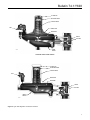
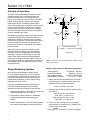
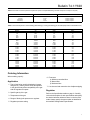
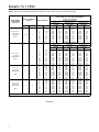
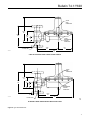
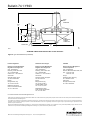
Bulletin 74.1:Y693 Table 2. Type Y693 Regulator Construction Materials MATERIAL PART name Aluminum Lower Casing Version Steel or Stainless Steel Lower Casing Version Body Cast iron WCB steel or Stainless steel Body Gasket Composition Composition Union Nut ---- Steel or Stainless steel Spring case Aluminum Aluminum, WCB steel or Stainless steel Lower casing Aluminum WCB steel or Stainless steel Orifice and bias spring Stainless steel Stainless steel Pusher post and stem Aluminum Stainless steel Lever assembly Steel Stainless steel Diaphragm Nitrile (NBR) or Fluorocarbon (FKM) Nitrile (NBR) or Fluorocarbon (FKM) Control spring, spring seat and split ring Plated steel Plated steel Diaphragm plate Aluminum and Steel Aluminum and Steel Disk and O-rings Nitrile (NBR) and Stainless steel, Fluorocarbon (FKM) and Stainless steel, PTFE and Stainless steel N itrile (NBR) and Stainless steel or Fluorocarbon (FKM) and Stainless steel or PTFE and Stainless steel 4. From Table 6, at 0.5 in. w.c. / 1 mbar set pressure and 40 psig inlet pressure, a Type Y693 will flow 8880 SCFH / 238 Nm3/h nitrogen. This satisfies the 5729 SCFH / 154 Nm3/h requirements. Capacity Information Table 6 gives typical nitrogen regulating capacities at selected inlet pressures and outlet pressure settings. Flows are in scfh (60°F and 14.7 psia) of 0.97 specific gravity nitrogen. For gases of other specific gravities, multiply the given capacity of nitrogen by 0.985, and divide by the square root of the appropriate specific gravity of the gas required. Then, if capacity is desired in normal cubic meters per hours at 0°C and 1.01325 bar, multiply scfh by 0.0268. To determine wide-open flow capacities for relief sizing, use the following formula: Q = 520 GT CgP1SIN 3417 C1 P P1 DEG where, Cg = gas sizing coefficient from Specifications table C1 = Cg / Cv or 33 from the Specifications table G = gas specific gravity (air = 1.0) P1abs = inlet pressure, psia (add 14.7 psi to gauge inlet pressure to obtain absolute inlet pressure) Q = flow rate, scfh Installation The regulator may be installed in any position as long as the flow through the body is in the direction indicated by the flow arrow attached to the body. Install the regulator as close as possible to the blanketed vessel using a straight run of pipe the same size or larger as the regulator body. Position the body and/or diaphragm spring case so it will not collect moisture or debris into the screened vent and also be self draining (as shown in Figure 3). If a block valve is required, install a full flow valve between the regulator and the blanketed vessel. Attach a downstream pressure control line to the female connection in the lower spring case. The female pressure connection is a 1/2 NPT in the steel or Stainless steel lower spring case and a 3/4 NPT for the aluminum lower spring case. Connect the other end of the control line to the vessel. To allow for self‑drainage, install the control line at an angle so that any liquid material will drain away from the regulator. See Figure 4 for the location of the external control line connection. External dimensions and connections are shown in Figure 4. T = absolute temperature in °R of gas at inlet (°F + 460) 5 Bulletin 74.1:Y693 Table 3. Materials Compatibility CORROSION INFORMATION Fluid Material Fluid Carbon Steel Cast Iron 316 Stainless Steel Acetic Acid, Air Free Acetic Acid Vapors Acetone Acetylene Alcohols C C A A A C C A A A B A A A A Hydrochloric Acid (Air Free) Hydrogen Hydrogen Peroxide Hydrogen Sulfide, Liquid Magnesium Hydroxide Aluminum Sulfate Ammonia Ammonium Chloride Ammonium Nitrate Ammonium Sulfate C A C A C C A C C C A A B A A Ammonium Sulfite Beer Benzene (Benzol) Benzoic Acid Boric Acid C B A C C C B A C C Butane Calcium Chloride (Alkaline) Carbon Dioxide, Dry Carbon Dioxide, Wet Carbon Disulfide A B A C A Carbon Tetrachloride Carbonic Acid Chlorine Gas, Dry Chlorine Gas, Wet Chlorine, Liquid Material Carbon Steel Cast Iron 316 Stainless Steel C A I.L. C A C A A C A C A A A A Methanol Methyl Ethyl Ketone Natural Gas Nitric Acid Petroleum Oils, Refined A A A C A A A A C A A A A B A A A A A A Phosphoric Acid (Air Free) Phosphoric Acid Vapors Potassium Chloride Potassium Hydroxide Propane C C B B A C C B B A A B A A A A B A C A A B A A A Silver Nitrate Sodium Acetate Sodium Carbonate Sodium Chloride Sodium Chromate C A A C A C A A C A A A A B A B C A C C B C A C C B B B C C Sodium Hydroxide Stearic Acid Sulfur Sulfur Dioxide, Dry Sulfur Trioxide, Dry A A A A A A C A A A A A A A A Chromic Acid Citric Acid Coke Oven Gas Copper Sulfate Ether C I.L. A C B C C A C B B B A B A Sulfuric Acid (Aerated) Sulfuric Acid (Air Free) Sulfurous Acid Trichloroethylene Water, Boiler Feed C C C B B C C C B C C C B A A Ethyl Chloride Ethylene Ethylene Glycol Formaldehyde Formic Acid C A A B I.L. C A A B C A A A A B Water, Distilled Water, Sea Zinc Chloride Zinc Sulfate ---- A B C C ---- A B C C ---- A B C A ---- B B A A C B B A A C A A A A C ---------------- ---------------- ---------------- ---------------- PTFE Nitrile (NBR) Fluorocarbon (FKM) Fluid PTFE Nitrile (NBR) Fluorocarbon (FKM) A A A A A A A A A A A A A A A A A B B B C A A C C C A C A+ A C C C B C A A A B C B C C C A B B A A A A A A+ C A A+ B Freon 22 Freon 114 Gasoline Hydrogen Gas Hydrogen Sulfide (Dry) Hydrogen Sulfide (Wet) Jet Fuel (JP-4) Natural Gas Natural Gas + H2S (Sour Gas) Nitric Acid (10%) Nitric Acid (50 to 100%) Nitrogen Oil (Fuel) Propane Sea Water Sulfur Dioxide Sulfuric Acid (to 50%) Sulfuric Acid (50 to 100%) Water (Ambient) Water at 200°F / 93°C A B A A A A A A A A B A A A A A A A A A C A A+ A C C A A+ B C C A A+ A A C C C A B C B A A C C A A C A A A A A A A A A A B Freon, Wet Freon, Dry Gasoline, Refined Glucose Hydrochloric Acid (Aerated) FLUID INFORMATION Fluid Acetic Acid (30%) Acetone Alcohol, Ethyl Alcohol, Methyl Ammonia, Anhydrous Ammonia, Gas (Hot) Benzene Brine (Calcium Chloride) Butadiene Gas Butane, Gas Butane, Liquid Carbon Tetrachloride Chlorine, Dry Chlorine, Wet Coke Oven Gas Ethyl Acetate Ethylene Glycol Freon 11 Freon 12 1. Mark owned by International Nickel Co. 2. Mark owned by Stelite Div., Cabot Corp. A+ - Best possible selection. A - Recommended. 6 B - Minor to moderate effect. Proceed with caution. C - Unsatisfactory. I.L. - Information lacking. Bulletin 74.1:Y693 Table 4. Flow Rate Conversion (Gas flow required to replace or displace Blanketing Gas with Pump-Out or Pump-In of Liquid) MULTIPLY MAXIMUM PUMP RATE IN: BY TO OBTAIN: U.S. GPM U.S. GPH Barrels/hour Barrels/day 8.021 0.1337 5.615 0.2340 SCFH air required SCFH air required SCFH air required SCFH air required Table 5. Gas Flow Required for Thermal Heating (Outbreathing) or Cooling (Inbreathing) per API 2000 (Interpolate for Intermediate sizes) VESSEL CAPACITY AIR FLOW RATE REQUIRED Barrels gal. SCFH nm3/h 60 100 500 1000 2000 2500 4200 21,000 42,000 84,000 60 100 500 1000 2000 1.6 2.7 13.4 26.8 53.6 3000 4000 5000 10,000 15,000 126,000 168,000 210,000 420,000 630,000 3000 4000 5000 10,000 15,000 80.4 107 134 268 402 20,000 25,000 30,000 35,000 40,000 840,000 1,050,000 1,260,000 1,470,000 1,680,000 20,000 24,000 28,000 31,000 34,000 536 643 750 831 911 45,000 50,000 60,000 70,000 80,000 1,890,000 2,100,000 2,520,000 2,940,000 3,360,000 37,000 40,000 44,000 48,000 52,000 992 1072 1179 1286 1394 90,000 100,000 120,000 140,000 160,000 3,780,000 4,200,000 5,040,000 5,880,000 6,720,000 56,000 60,000 68,000 75,000 82,000 1501 1608 1822 2010 2198 180,000 7,560,000 90,000 2412 Ordering Information When ordering, specify: Application 1. Type of gas being used for blanketing (nitrogen, fuel gas, etc.); list any factors such as impurities in the gas that may affect compatibility of the gas with the regulator trim parts. 2. Specific gravity of the gas 3. Temperature of the gas 4. Range of flowing inlet pressures to regulator 5. Regulator pressure setting 6. Flow rates a) Minimum controlled flow b) Normal flow c) Maximum flow 7. Line size and end connection size of adjacent piping Regulator Refer to the Specifications table on page 2. Carefully review the description of each specification and specify the desired selection wherever there is a choice to be made. Always specify the type number as identified in the Available Configurations specification. 7 Bulletin 74.1:Y693 Table 6. Typical Type Y693 Blanketing Regulator Capacities in Scfh / Nm3/h of 0.97 Specific Gravity Nitrogen SPRING RANGE, PART NUMBER AND COLOR control PRESSURE SETTING Deviation from Setpoint ±0.5 In. w.c. / ±1 mbar In. w.c. 0.5 to 2 in. w.c. / 1 to 5 mbar 1D892527022 INLET PRESSURE CAPACITIES IN SCFH / Nm3/h OF 0.97 SPECIFIC GRAVITY NITROGEN FOR 1-1/2 AND 2 in. / DN 40 AND 50 BODIES WITH A 1/2 in. / 13 mm ORIFICE 0.5(1) -0.5 to 1 In. w.c. / -1 to 2 mbar -0.5 to 2 In. w.c. / -1 to 5 mbar mbar psig bar SCFH Nm3/h SCFH Nm3/h SCFH Nm3/h 1(1) 2 5 10 20 40 60 80 100 125 150 0.14 0.34 0.69 1.4 2.8 4.1 5.5 6.9 8.6 10.3 750 1570 2500 5000 8800 12,100 7100 7100 7100 7100 20.1 42.1 67.0 134 236 324 190 190 190 190 750 1570 2500 5000 8800 12,100 15,400 15,200 14,200 12,200 20.1 42.1 67.0 134 236 324 413 407 381 327 750 1570 2500 5000 8800 12,100 15,400 18,600 22,700 26,700 20.1 42.1 67.0 134 236 324 413 498 608 716 Brown Deviation from Setpoint ±0.5 In. w.c. / ±1 mbar 0.5 to 2 in. w.c. / 1 to 5 mbar 1D892527022 1 3 Black 7 SCFH Nm3/h SCFH Nm3/h SCFH Nm3/h 2 0.14 0.34 0.69 1.4 2.8 4.1 5.5 6.9 8.6 10.3 750 1570 2500 5000 8800 12,100 7100 7100 7100 7100 20.1 42.1 67.0 134 236 324 190 190 190 190 1270 2280 3400 5200 8800 12,100 15,400 15,200 14,200 12,200 34.0 61.1 91.1 139 236 324 413 407 381 327 1270 2280 3400 5200 8800 12,100 15,400 18,600 22,700 26,700 34.0 61.1 91.1 139 236 324 413 498 608 716 7 2 5 10 20 40 60 80 100 125 150 0.14 0.34 0.69 1.4 2.8 4.1 5.5 6.9 8.6 10.3 750 1570 2500 5000 8800 12,100 11,200 11,200 11,200 11,200 20.1 42.1 67.0 134 236 324 300 300 300 300 1270 2280 3400 5200 8800 12,100 15,400 14,200 14,200 14,200 34.0 61.1 91.1 139 236 324 413 381 381 381 1270 2280 3400 5200 8800 12,100 15,400 18,600 22,700 26,700 34.0 61.1 91.1 139 236 324 413 498 608 716 17 2 5 10 20 40 60 80 100 125 150 0.14 0.34 0.69 1.4 2.8 4.1 5.5 6.9 8.6 10.3 710 1370 2110 3050 5580 10,200 14,200 18,600 11,200 11,200 19.0 36.7 56.5 81.7 150 273 381 498 300 300 1070 2030 3130 4260 8020 11,500 15,400 18,600 22,700 26,700 28.7 54.4 83.9 114 215 308 413 498 608 716 1070 2030 3130 4260 8020 11,500 15,400 18,600 22,700 26,700 28.7 54.4 83.9 114 215 308 413 498 608 716 Red 5 to 8 in. w.c. / 12 to 20 mbar 1D892727012 1. For set pressures less than 1 in. w.c. / 2 mbar use only Nitrile (NBR) elastomers. -continued- 8 -1 to 2 In. w.c. / -2 to 5 mbar 2 5 10 20 40 60 80 100 125 150 Brown 2 to 5 in. w.c. / 5 to 12 mbar 1D892627022 ±1 In. w.c. / ±2 mbar Bulletin 74.1:Y693 Table 6. Typical Type Y693 Blanketing Regulator Capacities in Scfh / Nm3/h of 0.97 Specific Gravity Nitrogen (continued) SPRING RANGE, PART NUMBER AND COLOR control PRESSURE SETTING Deviation from Setpoint ±1 In. w.c. / ±2 mbar In. w.c. 8 to 18 in. w.c. / 20 to 45 mbar 1D893227032 INLET PRESSURE CAPACITIES IN SCFH / Nm3/h OF 0.97 SPECIFIC GRAVITY NITROGEN FOR 1-1/2 AND 2 in. / DN 40 AND 50 BODIES WITH A 1/2 in. / 13 mm ORIFICE 11 ±2 In. w.c. / ±5 mbar mbar psig bar SCFH Nm3/h SCFH Nm3/h 27 2 5 10 20 40 60 80 100 125 150 0.14 0.34 0.69 1.4 2.8 4.1 5.5 6.9 8.6 10.3 660 1270 2130 3050 7110 9540 13,200 18,600 22,700 26,700 17.7 34.0 57.1 81.7 191 256 354 498 608 716 1020 1830 2840 4060 7610 12,100 15,400 18,600 22,700 26,700 27.3 49.0 76.1 109 204 324 413 498 608 716 Gray Deviation from Setpoint ±1 In. w.c. / ±2 mbar 18 to 32 in. w.c. / 45 to 80 mbar 1D893327032 20 50 Dark green 2 5 10 20 40 60 80 100 125 150 0.14 0.34 0.69 1.4 2.8 4.1 5.5 6.9 8.6 10.3 ±2 In. w.c. / ±5 mbar SCFH Nm3/h SCFH Nm3/h 590 810 1100 1520 2740 4060 6600 9140 22,700 26,700 15.8 21.7 29.5 40.7 73.4 109 177 245 608 716 710 1420 1830 3050 6090 10,200 15,400 18,600 22,700 26,700 19.0 38.1 49.0 81.7 163 273 413 498 608 716 Deviation from Setpoint ±0.1 In. w.c. / ±0.007 mbar 1 to 2 psig / 69 to 138 mbar 1H975827032 1 psig 69 Dark blue 2 5 10 20 40 60 80 100 0.14 0.34 0.69 1.4 2.8 4.1 5.5 6.9 ±0.2 In. w.c. / ±0.014 mbar SCFH Nm3/h SCFH Nm3/h 250 1100 1780 2640 4470 6500 9140 10,400 6.70 29.5 47.7 70.8 120 174 245 279 860 1830 2940 4870 8120 11,100 15,400 18,600 23.0 49.0 78.8 131 218 297 413 498 Deviation from Setpoint ±0.3 In. w.c. / ±0.021 mbar 1.5 to 3.3 psig / 103 to 228 mbar 1H975827032 Orange 3 psig 0.21 bar 5 10 20 40 60 80 100 0.34 0.69 1.4 2.8 4.1 5.5 6.9 ±0.6 In. w.c. / ±0.041 mbar SCFH Nm3/h SCFH Nm3/h 1220 2540 3860 7100 9340 13,200 15,800 32.7 68.1 103 190 250 354 423 1730 3400 5200 8880 12,100 15,400 18,600 46.4 91.1 139 238 324 413 498 -continued- 9 Bulletin 74.1:Y693 Table 6. Typical Type Y693 Blanketing Regulator Capacities in Scfh / Nm3/h of 0.97 Specific Gravity Nitrogen (continued) SPRING RANGE, PART NUMBER AND COLOR control PRESSURE SETTING Deviation from Setpoint ±0.5 In. w.c. / ±1 mbar psig 2 to 5 psig / 138 mbar to 0.3 bar 1P615427142 INLET PRESSURE CAPACITIES IN SCFH / Nm3/h OF 0.97 SPECIFIC GRAVITY NITROGEN FOR 1-1/2 AND 2 in. / DN 40 AND 50 BODIES WITH A 1/2 in. / 13 mm ORIFICE 3 ±1 In. w.c. / ±2 mbar bar psig bar SCFH Nm3/h SCFH Nm3/h 0.21 7 10 20 40 60 80 100 0.48 0.69 1.4 2.8 4.1 5.5 6.9 1400 2330 4060 6900 9740 12,800 15,200 37.5 62.4 109 185 261 343 407 2200 3050 5200 8880 12,100 15,400 18,600 59.0 81.7 139 238 324 413 498 Yellow Deviation from Setpoint ±0.6 In. w.c. / ±1 mbar 2 to 5.5 psig / 138 mbar to 0.4 bar 0Y066427022 5 0.35 Green Stripe 7 10 20 40 60 80 100 0.48 0.69 1.4 2.8 4.1 5.5 6.9 ±1 In. w.c. / ±2 mbar SCFH Nm3/h SCFH Nm3/h 1200 1420 2440 4260 5890 7510 9140 32.2 38.1 65.4 114 158 201 245 1600 2230 3760 6290 8730 11,400 14,200 42.9 59.8 101 169 234 306 381 Deviation from Setpoint ±0.6 In. w.c. / ±1 mbar 4 to 10 psig / 276 mbar to 0.7 bar 1H8024000A2 Silver 10 10 0.69 15 20 40 60 80 100 1.0 1.4 2.8 4.1 5.5 6.9 ±2 In. w.c. / ±5 mbar SCFH Nm3/h SCFH Nm3/h 1600 2030 3650 5080 6500 7920 42.9 54.4 97.8 136 174 212 2600 3500 6680 9300 11,900 14,900 69.7 93.8 179 249 319 399 Bulletin 74.1:Y693 3/4 npt VENT CONNECTION 11.88 / 302 14.00 / 356 5.88 / 149 2.94 / 75 1/2 NPT DOWNSTREAM CONTROL CONNection 10.38 / 264 1-1/2 AND 2 NPT 17.44 / 443 14B0812-A 7.06 / 179 STEEL OR STAINLESS STEEL LOWER CASING VERSION 3/4 NPT Vent connection 12.25 / 311 14.00 / 356 6.12 / 155 3.19 / 81 2.19 / 56 14B0813-A 1-1/2 AND 2 NPT 3/4 NPT downstream control connection 10.62 / 270 17.69 / 449 aLUMINUM LOWER CASING VERSION WITH A STEEL BODY IN. / mm Figure 4. Type Y693 Dimensions 11 Bulletin 74.1:Y693 3/4 NPT Vent connection 2.06 / 52 12.25 / 311 6.12 / 155 3.19 / 81 10.62 / 270 1-1/2 AND 2 NPT 3/4 NPT downstream control connection 17.69 / 449 IN. / mm 14B0814-A B2438 aLUMINUM LOWER CASING VERSION WITH A CAST IRON BODY Figure 4. Type Y693 Dimensions (continued) Industrial Regulators Natural Gas Technologies TESCOM Emerson Process Management Regulator Technologies, Inc. Emerson Process Management Regulator Technologies, Inc. Emerson Process Management Tescom Corporation USA - Headquarters McKinney, Texas 75070 USA Tel: +1 800 558 5853 Outside U.S. +1 972 548 3574 USA - Headquarters McKinney, Texas 75070 USA Tel: +1 800 558 5853 Outside U.S. +1 972 548 3574 USA - Headquarters Elk River, Minnesota 55330-2445, USA Tels: +1 763 241 3238 +1 800 447 1250 Asia-Pacific Shanghai 201206, China Tel: +86 21 2892 9000 Asia-Pacific Singapore 128461, Singapore Tel: +65 6770 8337 Europe Selmsdorf 23923, Germany Tel: +49 38823 31 287 Europe Bologna 40013, Italy Tel: +39 051 419 0611 Europe Bologna 40013, Italy Tel: +39 051 419 0611 Chartres 28008, France Tel: +33 2 37 33 47 00 Asia-Pacific Shanghai 201206, China Tel: +86 21 2892 9499 Middle East and Africa Dubai, United Arab Emirates Tel: +971 4811 8100 Middle East and Africa Dubai, United Arab Emirates Tel: +971 4811 8100 For further information visit www.fisherregulators.com The Emerson logo is a trademark and service mark of Emerson Electric Co. All other marks are the property of their prospective owners. Fisher is a mark owned by Fisher Controls International LLC, a business of Emerson Process Management. The contents of this publication are presented for informational purposes only, and while every effort has been made to ensure their accuracy, they are not to be construed as warranties or guarantees, express or implied, regarding the products or services described herein or their use or applicability. We reserve the right to modify or improve the designs or specifications of such products at any time without notice. Emerson Process Management Regulator Technologies, Inc. does not assume responsibility for the selection, use or maintenance of any product. Responsibility for proper selection, use and maintenance of any Emerson Process Management Regulator Technologies, Inc. product remains solely with the purchaser. ©Emerson Process Management Regulator Technologies, Inc., 1994, 2014; All Rights Reserved