1
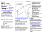
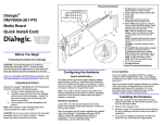
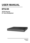
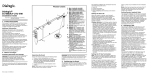
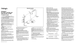
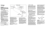
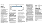
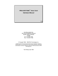
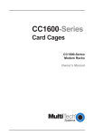
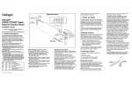
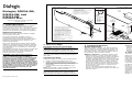
Physical Layout
Pinouts for the
Power Connector
Physical Description
1. CT Bus (H.100) connector
2. SW100 - Rotary switch used to set board
identification number
3. Green LED - Power On indicator
4. Yellow LEDs - User-defined #1 and #2
5. Red LED - Out of Service indicator
1
Dialogic®
DISI16-EW,
DISI24-EW, and
DISI32-EW
5
2
6
Copyright © 2006-2007 Dialogic Corporation.
All rights reserved.
3
4
5
1
2
3
4
5
6
To AC
Power
4
1
Chassis
Ground
3
Installation Guide
6
3
12
Connect Breakout Box and Power Supply
Power
Supply
2
-24/-70 Return
PC Sens
-24 Volts
-24/-70 Return
-24 Volts
-70 Volts
To
Telephone
Extensions
1. Product Description
The product data sheet, available at http://
www.dialogic.com/products/list.asp, provides a
functional description as well as information about
applications and configurations, features, and
technical specifications.
Refer to the Release Guide and the online Release
Update for your Dialogic system software release to
verify that the DISI is supported in the release and
for information on any new features or issues that
may relate to it.
The Regulatory Notices document that is packed with
each DISI board contains safety warnings and
national requirements for proper operation of
telecommunications equipment.
WARNING! This analog station interface
product is designed to be used only within the
walls of a single stand-alone building or
structure (i.e., on-premise). It is not designed
to sustain electrical overstress from external
sources and factors such as severe weather
conditions. Severe electrical overstress caused
by misuse of this interface product with cables
extending outside of the walls of a single standalone building or structure could cause property
damage and/or personal injury and/or death.
Such misuse voids the warranty for this
interface product.
2. Before You Begin
Protecting the Board from Damage
CAUTION: All computer boards are sensitive to
electrostatic discharge. Handle all static-sensitive
boards and components at a static-safe work area,
and observe anti-static precautions at all times.
If you are not familiar with ESD safety precautions,
visit http://www.dialogic.com/support/hwinstall to
learn more.
Unpacking the Board
Unpack the board according to the following steps:
1. Prepare a static-safeguarded work area.
2. Carefully remove the board from the shipping
carton and static-shielding bag. Handle the board
by the edges and avoid touching the board's
components.
3. Lay the board on the static-dissipative work
surface.
Note: Place boards in static-shielding bags when
carrying boards from station to station.
CAUTION: Do not remove the board from the antistatic packaging until you are ready to install it.
Observe proper anti-static precautions at all times.
Part number: 64-0161-02
24
32
31
30
28
19
27
18
9
29
20
1
11
2
12
21
3
22
4
13
8
23
14
5
15
6
16
7
8
RJ-11
Cables
10
26
25
Additional information about the DISI is available
from a number of sources.
10
9
Additional Information
DISI
Board
7
6. Power Budgeting Jumper P4 - 3-pin jumper
to set how the board responds to the
system power budgeting function
-P4 jumper in pins 2-3: Board adheres to
power budgeting values set by system.
-P4 jumper in pins 1-2: Board ignores
power budgeting values set by system.
Factory default is P4 jumper in pins 2-3.
7. Power supply connector - Connects to
external power supply
8. Breakout connector - Connects to telephone
breakout box
9. PCI Express connector - for x1 or larger PCI
Express Link connectors
10. Audio Input Jack - for music on hold feature
17
The Dialogic® DISI switching boards are full-size,
single-slot PCI Express boards. They provide
connectivity for up to 16, 24, or 32 station interfaces
and include conferencing, voice play/record, tone
detection and generation, and Caller ID capabilities.
Breakout
Cable
Breakout
Box
3. Configuring the Board
Setting the Board ID
When the system is started, each Dialogic telecom
board is assigned a board instance ID number that
programs can use to identify individual boards in a
multi-board system. The setting of SW100 controls
the generation of the instance numbers.
Windows* Systems: In a Windows system, leave
SW100 set to the 0 position (the factory default
setting) on all Dialogic telecom boards. This setting
causes the system software to assign instance
numbers geographically, based on the bus and slot
numbers. Note that there is no way to know what
the instance numbers will be until the system is
started and configured, and the instance number
for any given board is likely to change when there
is any change in the number or arrangement of
boards in the system.
You can read the ID numbers assigned to the
boards in the Configuration Manager tool after you
start the system.
Linux* Systems: In a Linux system, you must
explicitly specify the board ID numbers by setting
SW100 on each board to a different position (0-9
or A-F). Refer to the Configuration Guide in your
System Software documentation for further
information about the board ID numbers.
4. Choosing a Slot
The DISI board is a full length x1 form factor PCI
Express board that requires 25W of power. The
following explanation and guidelines are provided to
ensure proper configuration of the product.
Power Budgeting is a new feature, introduced in the
PCI Express Specification, that provides a mechanism
to enable a system to negotiate power consumption
requirements for add-in devices.
Per PCI Express Card Electromechanical Specification
Revision 1.0a or higher, a x1 add-in card can draw no
more than 10W in a x1 slot unless the board’s
required power is successfully negotiated and
allocated by the system (power budgeting). However,
implementation of power budgeting by a vendor's
system is not a compliance requirement per the PCI
Express Card Electromechanical Specification
Revision 1.0a or higher. Therefore, some chassis may
WARNING! Installing the DISI board in a x1
slot with the P4 jumper in position 1-2 will void
the warranty of the DISI board.
If the DISI will be connected to other telephony
boards via a CT Bus cable, you should install the
boards to minimize unused connectors on the CT Bus
cable (in addition to ensuring that the power
requirements are met):
■ Install boards in adjacent slots whenever possible.
■ If the DISI board will be connected to one or more
PCI boards, use the PCI Express slot(s) closest to
the PCI slots.
5. Installing the Board
WARNING! Unplug the equipment before
performing the procedures described here.
Failure to disconnect the power before you
open the chassis can result in personal injury.
Ensure that the system is disconnected from its
power source and from all telecommunications
links, networks, or modem lines whenever the
chassis cover is removed. Do not operate the
system with the cover removed.
CAUTION: To avoid possible damage to the board,
remove power from the computer before beginning
installation. Observe proper anti-static precautions at
all times while handling and installing the board.
To install the DISI board, perform the following steps:
1. Turn off all power to the system and disconnect
the system’s power cords.
2. Remove the computer’s cover.
3. Choose an empty PCI Express expansion slot and
remove the slot’s retaining screw and access
cover plate.
4. Insert the board’s edge connector into the bus
slot, and apply firm pressure to the top edge of
the board until the board is fully seated in the
edge connector.
5. Reinstall the retaining screw.
6. Repeat steps 1 through 5 for any additional
boards you are installing.
7. Connect the telephony boards together with a CT
Bus cable of the appropriate size (not included). If
possible, use a cable assembly that matches the
number of boards in your system. If the cable has
more than one unused connector, install the cable
so that all the unused connectors are at one end
of the cable.
8. Replace the computer’s cover.
9. Reconnect the computer’s power cord.
Audio Cable and Ferrite Clamp
A ferrite clamp is required on the audio cable to
reduce RFI emissions from the PCB audio jack and to
comply with the EN55022 Class B radio frequency
interference limits. Follow these instructions to
properly install the ferrite clamp:
1. Loop the cable once around the ferrite clamp,
keeping cable snug and as close as possible to the
plug to be installed into audio jack on the PCB.
2. Snap the ferrite clamp closed onto the cable.
3. Insert the plug into the audio jack.
7. Pinouts for the Breakout Connector
Signal
Pin
Signal
RING2
35
TIP2
2
RING1
36
TIP1
3
RING4
37
TIP4
4
RING3
38
TIP3
5
RING6
39
TIP6
6
RING5
40
TIP5
7
RING8
41
TIP8
8
RING7
42
TIP7
9
RING18
43
TIP18
10
RING20
44
TIP20
11
RING19
45
TIP19
12
RING17
46
TIP17
13
RING21
47
TIP21
14
RING22
48
TIP22
15
RING23
49
TIP23
16
RING24
50
TIP24
17
NOT USED
51
NOT USED
18
NOT USED
52
NOT USED
19
RING26
53
TIP26
20
RING25
54
TIP25
21
RING28
55
TIP28
22
RING27
56
TIP27
23
RING30
57
TIP30
24
RING29
58
TIP29
25
RING32
59
TIP32
26
RING31
60
TIP31
27
RING14
61
TIP14
Connect Board Using CBLTAC0X32 Telco
Adapter Cable
28
RING13
62
TIP13
29
RING16
63
TIP16
The CBLTAC0X32 Telco Adapter Cable converts the
68-pin connector on the DISI board into two standard
RJ21X Amphenol* connectors. Each RJ21X connector
carries up to 16 stations, depending on the DISI
analog station port density (16, 24, 32).
30
RING15
64
TIP15
31
RING10
65
TIP10
32
RING9
66
TIP9
33
RING12
67
TIP12
The CBLTAC0X32 is approximately 12 inches in
length. Standard 25 pair Amphenol* cables should be
used to extend the reach.
34
RING11
68
TIP11
The external power module generates -24 volts to
power the station interface loop and -70 volts for
ringing. The power module connects to a pre-wired
power cable attached to the DISI board.
6. Telephony Connection Options
The station ports on the DISI board are accessed
using a telephony connection box such as the
breakout box provided with the DISIBOBKIT breakout
box and cable kit. Alternatively, the CBLTAC0X32
Telco Adapter Cable can be used for installations with
a wall-mounted distribution frame and split 50 pair
telephone punch down blocks, or with a standard
rack-mount breakout solution (RJ121X to RJ11).
Follow the instructions for the two possible
connection scenarios:
Connect Board Using DISIBOBKIT
Breakout Box and Cable Kit
The breakout box can be mounted using screws or
double-sided tape. Follow one of the two sets below
to connect the breakout box to the board.
■ Mounting Breakout Box Using Screws
■ Mounting Breakout Box Using Double-Sided Tape
If this is the first Dialogic telecom board installed in
your system, you will need to install an appropriate
System Software version and configure the software
for the specific board(s) you are using. Refer to the
installation and configuration documentation that
accompanies the release for instructions.
Breakout Connector Pin Designations
1
The DISI board must be connected to an external
power supply. The power module is the
MSISCGBLPWRMOD MSI Global Power Module
Assembly. One power module is required per DISI
baseboard.
The DISI requires the use of a System Software
version that specifically supports it. Required Dialogic
System Software: System Release 6.0 PCI for
Windows Service Update 137 or higher; System
Release 6.1 for Linux Service Update 241 or higher.
Note: On the DISI24 (24-port board), only tip and
ring pins 1-24 are active. On the DISI16 (16-port
board), only tip and ring pins 1-16 are active.
Pin
Connect to Power Supply
8. After Installing the Board
If you are installing the DISI in a system that already
has System Software installed, you should verify that
the installed software version supports the board. If
not, you will need to obtain and install a Service
Update that does support the DISI before configuring
the system for the newly installed board(s).
Please refer to the Release Update document for upto-date information about support for PCI Express
boards and any known issues relating to their use.
9. Removing the Board
Removal of the DISI board is essentially the reverse
of the installation procedure:
1. Observe anti-static precautions.
2. Disconnect the telephony cables.
3. Remove the computer’s power cord.
4. Remove the computer’s cover.
5. Disconnect the CT Bus cable (if applicable).
6. Remove and set aside the board’s retaining screw.
7. Remove the board and place it static-protective
packaging.
10.Contacting Technical Support
Dialogic provides technical support for its products
through a network of value added distributors who
are trained to answer technical questions on installing
and configuring Dialogic products. If you are unsure
how to contact your support channel, please call
Dialogic in the United States at 973-967-6600 (9am 5pm EST) and we will assist in obtaining the
appropriate support channel. Outside the United
States please refer to http://www.dialogic.com/
support/contact to obtain local contact information.
Dialogic also provides direct support via Dialogic®
Pro™ Services agreements. For more details of direct
support from Dialogic please refer to http://
www.dialogic.com/support/DialogicPro.
11.Returning a Product
Doc. ID: 05-2536-002
not support this feature. Power Budgeting jumper P4
is designed to ensure proper configuration of the
product.
The DISI board must be installed in a slot that can be
allocated 25W.
If Power Budgeting is not implemented by a vendor's
system, the DISI board must be plugged into a x4 or
higher slot with the P4 jumper in position 1-2 (power
budgeting ignored). This is allowed per PCI Express
Card Electromechanical Specification Revision 1.0a or
higher because a x4 or greater slot must be able to
support a minimum of 25W.
If Power Budgeting is implemented by a vendor's
system, the DISI board can be plugged into a x1 slot
but the P4 jumper must be in position pins 2-3
(power budgeting adhered to).
To return a board for warranty repair or any other
returns, please refer to the following:
http://www.dialogic.com/support/hwfaults
Dialogic® is a registered trademark of Dialogic Corporation.
Dialogic's trademarks may be used publicly only with
permission from Dialogic. Such permission may only be
granted by Dialogic’s legal department. The names of actual
companies and products mentioned herein are the
trademarks of their respective owners.