1
®
'HOO 2SWL3OH[ *;DQG*;S
0LQL7RZHU0DQDJHG3&6\VWHPV
5()(5(1&($1'
,167$//$7,21*8,'(
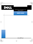
ZZZGHOOFRP
____________________
Information in this document is subject to change without notice.
© 1994–1998 Dell Computer Corporation. All rights reserved.
Reproduction in any manner whatsoever without the written permission of Dell Computer Corporation is strictly forbidden.
Trademarks used in this text: Dell, OptiPlex, and the DELL logo are registered trademarks, Dell OpenManage is a trademark, and
DellWare is a registered service mark of Dell Computer Corporation; Intel, LanDesk, and Pentium are registered trademarks and MMX
is a trademark of Intel Corporation; Microsoft, MS-DOS, Windows, and Windows NT are registered trademarks and Windows for
Workgroups is a trademark of Microsoft Corporation; IBM and OS/2 are registered trademarks of International Business Machines
Corporation; 3Com and EtherLink are registered trademarks and Fast EtherLink is a trademark of 3Com Corporation; VESA is a registered
trademark of Video Electronics Standards Association; UNIX is a registered trademark of UNIX System Laboratories, Inc., a wholly
owned subsidiary of Novell, Inc. As an ENERGY STAR Partner, Dell Computer Corporation has determined that this product meets the
ENERGY STAR guidelines for energy efficiency.
Other trademarks and trade names may be used in this document to refer to either the entities claiming the marks and names or their
products. Dell Computer Corporation disclaims any proprietary interest in trademarks and trade names other than its own.
July 1998
P/N 9303E
6DIHW\,QVWUXFWLRQV
Use the following safety guidelines to help protect your computer system from potential damage and to ensure your own personal safety.
:KHQ8VLQJ<RXU&RPSXWHU6\VWHP
As you use your computer system, observe the following safety guidelines.
:$51,1*'RQRWRSHUDWH\RXUFRPSXWHUV\VWHPZLWKDQ\FRYHUVLQFOXG
LQJFRPSXWHUFRYHUVEH]HOVILOOHUEUDFNHWVIURQWSDQHOLQVHUWVDQGVRRQ
UHPRYHG
To help avoid damaging your computer, be sure the voltage selection switch on
the power supply is set to match the AC power available at your location:
—
115 volts (V)/60 hertz (Hz) in most of North and South America and some Far
Eastern countries such as Japan, South Korea, and Taiwan
—
230 V/50 Hz in most of Europe, the Middle East, and the Far East
Also be sure your monitor and attached peripherals are electrically rated to operate with the AC power available in your location.
Before working inside the computer, unplug the system to help prevent electric
shock or system board damage. Certain system board components continue to
receive power any time the computer is connected to AC power.
To help avoid possible damage to the system board, wait 5 seconds after turning
off the system before disconnecting a device from the computer.
To help prevent electric shock, plug the computer and peripheral power cables
into properly grounded power sources. These cables are equipped with
three-prong plugs to help ensure proper grounding. Do not use adapter plugs or
remove the grounding prong from a cable. If you must use an extension cable,
use a three-wire cable with properly grounded plugs.
To help protect your computer system from sudden, transient increases and
decreases in electrical power, use a surge suppressor, line conditioner, or uninterruptible power supply (UPS).
Be sure nothing rests on your computer system’s cables and that the cables are
not located where they can be stepped on or tripped over.
v
Do not spill food or liquids on your computer. If the computer gets wet, consult
your Diagnostics and Troubleshooting Guide.
Do not push any objects into the openings of your computer. Doing so can cause
fire or electric shock by shorting out interior components.
Keep your computer away from radiators and heat sources. Also, do not block
cooling vents. Avoid placing loose papers underneath your computer; do not
place your computer in a closed-in wall unit or on a bed, sofa, or rug.
(UJRQRPLF&RPSXWLQJ+DELWV
:$51,1*,PSURSHURUSURORQJHGNH\ERDUGXVHPD\UHVXOWLQLQMXU\
For comfort and efficiency, observe the following ergonomic guidelines when setting
up and using your computer system:
vi
Position your system so that the monitor and keyboard are directly in front of you
as you work. Special shelves are available (from Dell and other sources) to help
you correctly position your keyboard.
Set the monitor at a comfortable viewing distance (usually 510 to 610 millimeters
[20 to 24 inches] from your eyes).
Make sure the monitor screen is at eye level or slightly lower when you are sitting
in front of the monitor.
Adjust the tilt of the monitor, its contrast and brightness settings, and the lighting
around you (such as overhead lights, desk lamps, and the curtains or blinds on
nearby windows) to minimize reflections and glare on the monitor screen.
Use a chair that provides good lower back support.
Keep your forearms horizontal with your wrists in a neutral, comfortable position
while using the keyboard or mouse.
Always leave space to rest your hands while using the keyboard or mouse.
Let your upper arms hang naturally at your sides.
Sit erect, with your feet resting on the floor and your thighs level.
When sitting, make sure the weight of your legs is on your feet and not on the
front of your chair seat. Adjust your chair’s height or use a footrest, if necessary,
to maintain proper posture.
Vary your work activities. Try to organize your work so that you do not have to
type for extended periods of time. When you stop typing, try to do things that
use both hands.
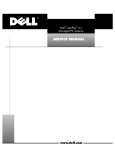
monitor screen at or below eye level
wrists relaxed and flat
monitor and
keyboard
positioned
directly in
front of user
arms at desk level
feet flat on
the floor
:KHQ:RUNLQJ,QVLGH<RXU&RPSXWHU
Before you remove the computer cover, perform the following steps in the sequence
indicated.
&$87,21'RQRWDWWHPSWWRVHUYLFHWKHFRPSXWHUV\VWHP\RXUVHOIH[FHSW
DVH[SODLQHGLQWKLVJXLGHDQGHOVHZKHUHLQ'HOOGRFXPHQWDWLRQ$OZD\V
IROORZLQVWDOODWLRQDQGVHUYLFHLQVWUXFWLRQVFORVHO\
7RKHOSDYRLGSRVVLEOHGDPDJHWRWKHV\VWHPERDUGZDLWXQWLOWKH/('RQ
WKHULVHUERDUGVHH)LJXUHKDVJRQHRXWDIWHU\RXWXUQRIIWKHV\VWHP
EHIRUHUHPRYLQJDFRPSRQHQWIURPWKHV\VWHPERDUGRUGLVFRQQHFWLQJD
SHULSKHUDOGHYLFHIURPWKHFRPSXWHU
7RXFKDQXQSDLQWHGPHWDOVXUIDFHRQWKHFKDVVLVVXFKDVWKHPHWDO
DURXQGWKHFDUGVORWRSHQLQJVDWWKHEDFNRIWKHFRPSXWHUEHIRUH
WRXFKLQJDQ\WKLQJLQVLGH\RXUFRPSXWHU
While you work, periodically touch an unpainted metal surface on the computer
chassis to dissipate any static electricity that might harm internal components.
7XUQRII\RXUFRPSXWHUDQGDQ\SHULSKHUDOV
vii
'LVFRQQHFW\RXUFRPSXWHUDQGSHULSKHUDOVIURPWKHLUSRZHUVRXUFHV
$OVRGLVFRQQHFWDQ\WHOHSKRQHRUWHOHFRPPXQLFDWLRQOLQHVIURPWKH
FRPSXWHU
Doing so reduces the potential for personal injury or shock.
In addition, take note of these safety guidelines when appropriate:
When you disconnect a cable, pull on its connector or on its strain-relief loop, not
on the cable itself. Some cables have a connector with locking tabs; if you are disconnecting this type of cable, press in on the locking tabs before disconnecting
the cable. As you pull connectors apart, keep them evenly aligned to avoid bending any connector pins. Also, before you connect a cable, make sure both
connectors are correctly oriented and aligned.
Handle components and cards with care. Don’t touch the components or contacts on a card. Hold a card by its edges or by its metal mounting bracket. Hold a
component such as a microprocessor chip by its edges, not by its pins.
%DWWHU\:DUQLQJ
:$51,1*
7KHUHLVDGDQJHURIDQHZEDWWHU\H[SORGLQJLILWLVLQFRUUHFWO\LQVWDOOHG
5HSODFHWKHEDWWHU\RQO\ZLWKWKHVDPHRUHTXLYDOHQWW\SHUHFRPPHQGHG
E\WKHPDQXIDFWXUHU 'LVFDUGXVHGEDWWHULHVDFFRUGLQJWRWKHPDQXIDF
WXUHU·VLQVWUXFWLRQV
3URWHFWLQJ$JDLQVW(OHFWURVWDWLF'LVFKDUJH
Static electricity can harm delicate components inside your computer. To prevent
static damage, discharge static electricity from your body before you touch any of
your computer’s electronic components, such as the microprocessor. You can do so
by touching an unpainted metal surface on the computer chassis.
As you continue to work inside the computer, periodically touch an unpainted metal
surface to remove any static charge your body may have accumulated.
You can also take the following steps to prevent damage from electrostatic discharge
(ESD):
viii
When unpacking a static-sensitive component from its shipping carton, do not
remove the component from the antistatic packing material until you are ready to
install the component in your computer. Just before unwrapping the antistatic
packaging, be sure to discharge static electricity from your body.
When transporting a sensitive component, first place it in an antistatic container
or packaging.
Handle all sensitive components in a static-safe area. If possible, use antistatic
floor pads and workbench pads.
The following caution may appear throughout this document to remind you of these
precautions:
&$87,216HH´3URWHFWLQJ$JDLQVW(OHFWURVWDWLF'LVFKDUJHµLQWKHVDIHW\
LQVWUXFWLRQVDWWKHIURQWRIWKLVJXLGH
ix
x
3UHIDFH
$ERXW7KLV*XLGH
This guide is intended for anyone who uses a Dell OptiPlex GX1 or GX1p mini tower
Managed PC system. It can be used by both first-time and experienced computer
users who want to learn about the features and operation of the systems or who
want to upgrade their computers. The chapters and appendixes are summarized as
follows:
Everyone should read Chapter 1, “Introduction,” for an overview of the system
features, instructions on how to access the online System User’s Guide, and
information on where to get help if you need it.
Everyone should read the first several sections of Chapter 2, “Using the System
Setup Program,” to become familiar with this important program. Only users
who want to make configuration changes to their system or who want to use the
password features need to read the rest of Chapter 2.
Users who add or remove an Industry-Standard Architecture (ISA) expansion card
should read Chapter 3, “Using the ISA Configuration Utility.”
Users who want to change the default configuration of the system’s integrated
video and audio controllers or who want to connect their system to a network
should read Chapter 4, “Using Integrated Devices.” This chapter describes the
configuration software provided for the integrated video and audio controllers and
provides information on connecting the system to a network, configuring the network interface controller (NIC), and installing drivers for the NIC.
Chapter 5, “Working Inside Your Computer,” Chapter 6, “Installing System Board
Options,” and Chapter 7, “Installing Drives,” are intended for users who want to
install or remove options inside the computer, such as dual in-line memory modules (DIMMs), additional video memory, expansion cards, or drives.
Appendix A, “Technical Specifications,” is intended primarily as reference material for users interested in learning more about the details of the system.
Appendix B, “ISA Configuration Utility Messages,” describes error messages
generated by the ISA Configuration Utility (ICU), possible causes, and corrective
actions.
Appendix C, “Regulatory Notices,” is for users who are interested in which regulatory agencies have tested and approved the Dell OptiPlex GX1 and GX1p mini
tower systems.
xi
Appendix D, “Warranties and Return Policy,” describes the warranty for your Dell
system and the “Total Satisfaction” Return Policy.
:DUUDQW\DQG5HWXUQ3ROLF\,QIRUPDWLRQ
Dell Computer Corporation (“Dell”) manufactures its hardware products from parts
and components that are new or equivalent to new in accordance with industrystandard practices. For information about the Dell warranty for your system, see
Appendix D, “Warranties and Return Policy.”
2WKHU'RFXPHQWV<RX0D\1HHG
Besides this Reference and Installation Guide, the following documentation is
included with your system:
The Getting Started sheet provides step-by-step instructions for setting up your
computer system.
The Windows-based online System User’s Guide contains important information
about your computer system. This document includes descriptions of system
features, instructions on installing and configuring drivers and utilities, information on the System Setup program and ISA Configuration Utility, and instructions
for attaching devices to the connectors on your computer’s back panel.
The Frequently Asked Questions cards provide detailed answers to questions
that are often asked by Dell computer users. Be sure to read these cards before
calling Dell for technical assistance.
The Diagnostics and Troubleshooting Guide includes troubleshooting procedures
and instructions for using the Dell Diagnostics to test your computer system.
You may also have one or more of the following documents.
NOTE: Documentation updates are sometimes included with your system to describe
changes to your system or software. Always read these updates before consulting
any other documentation because the updates often contain the latest information.
xii
Operating system documentation is included if you ordered your operating system software from Dell. This documentation describes how to install (if
necessary), configure, and use your operating system software.
Documentation is included with any options you purchase separately from your
system. This documentation includes information that you need to configure and
install these options in your Dell computer. Installation instructions for the
options are included in this Reference and Installation Guide.
Technical information files—sometimes called “readme” files—may be installed
on your hard-disk drive to provide last-minute updates about technical
changes to your system or advanced technical reference material intended for
experienced users or technicians.
1RWDWLRQDO&RQYHQWLRQV
The following subsections describe notational conventions used in this document.
:DUQLQJV&DXWLRQV1RWHV
Throughout this guide, there may be blocks of text printed in bold type or in italic type.
These blocks are warnings, cautions, and notes, and they are used as follows:
:$51,1*$:$51,1*LQGLFDWHVWKHSRWHQWLDOIRUERGLO\KDUPDQGWHOOV
\RXKRZWRDYRLGWKHSUREOHP
&$87,21$&$87,21LQGLFDWHVHLWKHUSRWHQWLDOGDPDJHWRKDUGZDUHRU
ORVVRIGDWDDQGWHOOV\RXKRZWRDYRLGWKHSUREOHP
NOTE: A NOTE indicates important information that helps you make better use of
your computer system.
7\SRJUDSKLFDO&RQYHQWLRQV
The following list defines (where appropriate) and illustrates typographical conventions used as visual cues for specific elements of text throughout this document:
Keycaps, the labeling that appears on the keys on a keyboard, are enclosed in
angle brackets.
Example: <Enter>
Key combinations are series of keys to be pressed simultaneously (unless otherwise indicated) to perform a single function.
Example: <Ctrl><Alt><Enter>
Commands presented in lowercase bold are for reference purposes only and are
not intended to be typed when referenced.
Example: “Use the format command to . . . .”
In contrast, commands presented in the Courier New font are part of an instruction and intended to be typed.
Example: “Type format a: to format the diskette in drive A.”
Filenames and directory names are presented in lowercase bold.
Examples: autoexec.bat and c:\windows
Syntax lines consist of a command and all its possible parameters. Commands
are displayed in lowercase bold; variable parameters (those for which you substitute a value) are displayed in lowercase italics; constant parameters are displayed
in lowercase bold. The brackets indicate items that are optional.
Example: del [drive:] [path] filename [/p]
xiii
Command lines consist of a command and may include one or more of the command’s possible parameters. Command lines are presented in the Courier New
font.
Example: del c:\myfile.doc
Screen text is text that appears on the screen of your monitor or display. It can be
a system message, for example, or it can be text that you are instructed to type
as part of a command (referred to as a command line). Screen text is presented
in the Courier New font.
Example: The following message appears on your screen:
No boot device available
Example: “Type md c:\programs and press <Enter>.”
Variables are placeholders for which you substitute a value. They are presented in
italics.
Example: DIMM_x (where x represents the DIMM socket designation).
xiv
&RQWHQWV
&KDSWHU
,QWURGXFWLRQ System Features . . . . . . . . . . . . . . . . . . . . . . . . . . . . . . . . . . . . . . . . . . . . . . . . . . . 1-1
Hardware Features. . . . . . . . . . . . . . . . . . . . . . . . . . . . . . . . . . . . . . . . . . . . . . 1-2
Software Features . . . . . . . . . . . . . . . . . . . . . . . . . . . . . . . . . . . . . . . . . . . . . . 1-4
Manageability Features . . . . . . . . . . . . . . . . . . . . . . . . . . . . . . . . . . . . . . . . . . 1-5
Dell OpenManage Program. . . . . . . . . . . . . . . . . . . . . . . . . . . . . . . . . . . . 1-5
PXE . . . . . . . . . . . . . . . . . . . . . . . . . . . . . . . . . . . . . . . . . . . . . . . . . . . . . . 1-7
Wakeup On LAN . . . . . . . . . . . . . . . . . . . . . . . . . . . . . . . . . . . . . . . . . . . . 1-8
Auto Power On . . . . . . . . . . . . . . . . . . . . . . . . . . . . . . . . . . . . . . . . . . . . . 1-8
Security Features . . . . . . . . . . . . . . . . . . . . . . . . . . . . . . . . . . . . . . . . . . . . . . . 1-8
Chassis Intrusion. . . . . . . . . . . . . . . . . . . . . . . . . . . . . . . . . . . . . . . . . . . . 1-8
Security Cable Slot and Padlock Ring . . . . . . . . . . . . . . . . . . . . . . . . . . . . 1-9
Passwords. . . . . . . . . . . . . . . . . . . . . . . . . . . . . . . . . . . . . . . . . . . . . . . . . 1-9
Using the Power Switch . . . . . . . . . . . . . . . . . . . . . . . . . . . . . . . . . . . . . . . . . . . . 1-10
ENERGY STAR Compliance. . . . . . . . . . . . . . . . . . . . . . . . . . . . . . . . . . . . . . . . . . 1-10
Important Note for Windows 95 Users . . . . . . . . . . . . . . . . . . . . . . . . . . . . . . . . . 1-11
Intel PIIX4 INF Update Installer for Windows 95. . . . . . . . . . . . . . . . . . . . . . . . . . 1-11
Accessing Online Documentation . . . . . . . . . . . . . . . . . . . . . . . . . . . . . . . . . . . . . 1-12
Getting Help . . . . . . . . . . . . . . . . . . . . . . . . . . . . . . . . . . . . . . . . . . . . . . . . . . . . . 1-13
&KDSWHU
8VLQJWKH6\VWHP6HWXS3URJUDP Entering the System Setup Program. . . . . . . . . . . . . . . . . . . . . . . . . . . . . . . . . . . .
System Setup Screens . . . . . . . . . . . . . . . . . . . . . . . . . . . . . . . . . . . . . . . . . . . . . .
Using the System Setup Program . . . . . . . . . . . . . . . . . . . . . . . . . . . . . . . . . . . . . .
System Setup options . . . . . . . . . . . . . . . . . . . . . . . . . . . . . . . . . . . . . . . . . . . . . . .
Time . . . . . . . . . . . . . . . . . . . . . . . . . . . . . . . . . . . . . . . . . . . . . . . . . . . . . . . . .
Date . . . . . . . . . . . . . . . . . . . . . . . . . . . . . . . . . . . . . . . . . . . . . . . . . . . . . . . .
Diskette Drive A and Diskette Drive B . . . . . . . . . . . . . . . . . . . . . . . . . . . . . . .
Drives: Primary and Secondary . . . . . . . . . . . . . . . . . . . . . . . . . . . . . . . . . . . .
2-1
2-2
2-3
2-4
2-5
2-5
2-5
2-5
xv
Reserved Memory . . . . . . . . . . . . . . . . . . . . . . . . . . . . . . . . . . . . . . . . . . . . . . 2-6
CPU Speed. . . . . . . . . . . . . . . . . . . . . . . . . . . . . . . . . . . . . . . . . . . . . . . . . . . . 2-7
Num Lock. . . . . . . . . . . . . . . . . . . . . . . . . . . . . . . . . . . . . . . . . . . . . . . . . . . . . 2-7
Chassis Intrusion . . . . . . . . . . . . . . . . . . . . . . . . . . . . . . . . . . . . . . . . . . . . . . . 2-7
DAC Snoop . . . . . . . . . . . . . . . . . . . . . . . . . . . . . . . . . . . . . . . . . . . . . . . . . . . 2-8
ACPI . . . . . . . . . . . . . . . . . . . . . . . . . . . . . . . . . . . . . . . . . . . . . . . . . . . . . . . . . 2-8
Keyboard Errors . . . . . . . . . . . . . . . . . . . . . . . . . . . . . . . . . . . . . . . . . . . . . . . . 2-8
System Password . . . . . . . . . . . . . . . . . . . . . . . . . . . . . . . . . . . . . . . . . . . . . . 2-8
Password Status . . . . . . . . . . . . . . . . . . . . . . . . . . . . . . . . . . . . . . . . . . . . . . . 2-9
Boot Sequence . . . . . . . . . . . . . . . . . . . . . . . . . . . . . . . . . . . . . . . . . . . . . . . . 2-9
Diskette First . . . . . . . . . . . . . . . . . . . . . . . . . . . . . . . . . . . . . . . . . . . . . . 2-9
Hard Disk Only . . . . . . . . . . . . . . . . . . . . . . . . . . . . . . . . . . . . . . . . . . . . . 2-9
Device List . . . . . . . . . . . . . . . . . . . . . . . . . . . . . . . . . . . . . . . . . . . . . . . . 2-9
Setup Password. . . . . . . . . . . . . . . . . . . . . . . . . . . . . . . . . . . . . . . . . . . . . . . 2-12
Auto Power On . . . . . . . . . . . . . . . . . . . . . . . . . . . . . . . . . . . . . . . . . . . . . . . 2-12
Power Management . . . . . . . . . . . . . . . . . . . . . . . . . . . . . . . . . . . . . . . . . . . 2-12
Saving Monitor Power . . . . . . . . . . . . . . . . . . . . . . . . . . . . . . . . . . . . . . 2-12
Saving EIDE Hard-Disk Drive Power. . . . . . . . . . . . . . . . . . . . . . . . . . . . 2-13
Wakeup On LAN . . . . . . . . . . . . . . . . . . . . . . . . . . . . . . . . . . . . . . . . . . . . . . 2-14
Sound . . . . . . . . . . . . . . . . . . . . . . . . . . . . . . . . . . . . . . . . . . . . . . . . . . . . . . 2-14
NIC . . . . . . . . . . . . . . . . . . . . . . . . . . . . . . . . . . . . . . . . . . . . . . . . . . . . . . . . . 2-14
Mouse . . . . . . . . . . . . . . . . . . . . . . . . . . . . . . . . . . . . . . . . . . . . . . . . . . . . . . 2-14
Serial Port 1 and Serial Port 2 . . . . . . . . . . . . . . . . . . . . . . . . . . . . . . . . . . . . 2-14
Parallel Port . . . . . . . . . . . . . . . . . . . . . . . . . . . . . . . . . . . . . . . . . . . . . . . . . . 2-15
Parallel Mode . . . . . . . . . . . . . . . . . . . . . . . . . . . . . . . . . . . . . . . . . . . . . . . . . 2-15
IDE Hard Disk. . . . . . . . . . . . . . . . . . . . . . . . . . . . . . . . . . . . . . . . . . . . . . . . . 2-15
Diskette . . . . . . . . . . . . . . . . . . . . . . . . . . . . . . . . . . . . . . . . . . . . . . . . . . . . . 2-15
Speaker . . . . . . . . . . . . . . . . . . . . . . . . . . . . . . . . . . . . . . . . . . . . . . . . . . . . . 2-16
System Data options . . . . . . . . . . . . . . . . . . . . . . . . . . . . . . . . . . . . . . . . . . . 2-16
Using the System Password Feature . . . . . . . . . . . . . . . . . . . . . . . . . . . . . . . . . . 2-16
Assigning a System Password. . . . . . . . . . . . . . . . . . . . . . . . . . . . . . . . . . . . 2-17
Using Your System Password to Secure Your System . . . . . . . . . . . . . . . . . 2-18
Deleting or Changing an Existing System Password . . . . . . . . . . . . . . . . . . . 2-19
Using the Setup Password Feature . . . . . . . . . . . . . . . . . . . . . . . . . . . . . . . . . . . 2-20
Assigning a Setup Password . . . . . . . . . . . . . . . . . . . . . . . . . . . . . . . . . . . . . 2-20
Operating With a Setup Password Enabled. . . . . . . . . . . . . . . . . . . . . . . . . . 2-20
Deleting or Changing an Existing Setup Password . . . . . . . . . . . . . . . . . . . . 2-21
Disabling a Forgotten Password . . . . . . . . . . . . . . . . . . . . . . . . . . . . . . . . . . . . . . 2-21
Responding to Error Messages. . . . . . . . . . . . . . . . . . . . . . . . . . . . . . . . . . . . . . . 2-22
xvi
&KDSWHU
8VLQJWKH,6$&RQILJXUDWLRQ8WLOLW\ Quick Start. . . . . . . . . . . . . . . . . . . . . . . . . . . . . . . . . . . . . . . . . . . . . . . . . . . . . . . . 3-2
About the ICU . . . . . . . . . . . . . . . . . . . . . . . . . . . . . . . . . . . . . . . . . . . . . . . . . . . . . 3-3
ICU Database . . . . . . . . . . . . . . . . . . . . . . . . . . . . . . . . . . . . . . . . . . . . . . . . . . 3-3
When to Run the ICU . . . . . . . . . . . . . . . . . . . . . . . . . . . . . . . . . . . . . . . . . . . . . . . 3-3
Preparing to Use the ICU. . . . . . . . . . . . . . . . . . . . . . . . . . . . . . . . . . . . . . . . . . . . . 3-4
Backing Up the ICU Diskette . . . . . . . . . . . . . . . . . . . . . . . . . . . . . . . . . . . . . . 3-4
Starting the ICU . . . . . . . . . . . . . . . . . . . . . . . . . . . . . . . . . . . . . . . . . . . . . . . . . . . . 3-5
Accessing Help. . . . . . . . . . . . . . . . . . . . . . . . . . . . . . . . . . . . . . . . . . . . . . . . . 3-5
Making Selections in the ICU . . . . . . . . . . . . . . . . . . . . . . . . . . . . . . . . . . . . . . 3-5
Adding a Listed Card . . . . . . . . . . . . . . . . . . . . . . . . . . . . . . . . . . . . . . . . . . . . . . . . 3-6
Adding an Unlisted Card . . . . . . . . . . . . . . . . . . . . . . . . . . . . . . . . . . . . . . . . . . . . . 3-9
Modifying a Card . . . . . . . . . . . . . . . . . . . . . . . . . . . . . . . . . . . . . . . . . . . . . . . . . . 3-11
Removing a Card . . . . . . . . . . . . . . . . . . . . . . . . . . . . . . . . . . . . . . . . . . . . . . . . . . 3-12
Viewing Resources . . . . . . . . . . . . . . . . . . . . . . . . . . . . . . . . . . . . . . . . . . . . . . . . 3-13
Saving the System Configuration . . . . . . . . . . . . . . . . . . . . . . . . . . . . . . . . . . . . . 3-14
Exiting From the ICU . . . . . . . . . . . . . . . . . . . . . . . . . . . . . . . . . . . . . . . . . . . . . . . 3-14
Locking and Unlocking Cards . . . . . . . . . . . . . . . . . . . . . . . . . . . . . . . . . . . . . . . . 3-14
Locking and Unlocking All Resources . . . . . . . . . . . . . . . . . . . . . . . . . . . . . . 3-15
Locking and Unlocking Configuration Resources . . . . . . . . . . . . . . . . . . . . . . 3-15
&KDSWHU
8VLQJ,QWHJUDWHG'HYLFHV Video Controller . . . . . . . . . . . . . . . . . . . . . . . . . . . . . . . . . . . . . . . . . . . . . . . . . . . .
Reinstalling DirectX and Video Drivers . . . . . . . . . . . . . . . . . . . . . . . . . . . . . . .
Audio Controller. . . . . . . . . . . . . . . . . . . . . . . . . . . . . . . . . . . . . . . . . . . . . . . . . . . .
NIC. . . . . . . . . . . . . . . . . . . . . . . . . . . . . . . . . . . . . . . . . . . . . . . . . . . . . . . . . . . . . .
Network Cable Requirements . . . . . . . . . . . . . . . . . . . . . . . . . . . . . . . . . . . . .
Setting the Network Frame Type . . . . . . . . . . . . . . . . . . . . . . . . . . . . . . . . . . .
Using 3Com EtherDisk XL Version 3.01 Diskettes. . . . . . . . . . . . . . . . . . . . . .
Configuring the NIC . . . . . . . . . . . . . . . . . . . . . . . . . . . . . . . . . . . . . . . . . . . . .
Windows NT 4.0 NIC . . . . . . . . . . . . . . . . . . . . . . . . . . . . . . . . . . . . . . . .
Windows NT 3.5x NIC. . . . . . . . . . . . . . . . . . . . . . . . . . . . . . . . . . . . . . . .
Windows 95 or Windows 98 NIC . . . . . . . . . . . . . . . . . . . . . . . . . . . . . . .
Windows for Workgroups NIC . . . . . . . . . . . . . . . . . . . . . . . . . . . . . . . . .
MS-DOS NIC . . . . . . . . . . . . . . . . . . . . . . . . . . . . . . . . . . . . . . . . . . . . . . .
&KDSWHU
4-1
4-1
4-3
4-3
4-4
4-4
4-4
4-5
4-5
4-6
4-7
4-8
4-9
:RUNLQJ,QVLGH<RXU&RPSXWHU Before You Begin . . . . . . . . . . . . . . . . . . . . . . . . . . . . . . . . . . . . . . . . . . . . . . . . . .
Safety First—For You and Your Computer . . . . . . . . . . . . . . . . . . . . . . . . . . . .
Unpacking Your Hardware Option . . . . . . . . . . . . . . . . . . . . . . . . . . . . . . . . . .
Removing the Computer Cover. . . . . . . . . . . . . . . . . . . . . . . . . . . . . . . . . . . . . . . .
Replacing the Computer Cover . . . . . . . . . . . . . . . . . . . . . . . . . . . . . . . . . . . . . . . .
5-1
5-1
5-2
5-2
5-4
xvii
Inside Your Computer . . . . . . . . . . . . . . . . . . . . . . . . . . . . . . . . . . . . . . . . . . . . . . . 5-5
Jumpers . . . . . . . . . . . . . . . . . . . . . . . . . . . . . . . . . . . . . . . . . . . . . . . . . . . . . . 5-6
Switches . . . . . . . . . . . . . . . . . . . . . . . . . . . . . . . . . . . . . . . . . . . . . . . . . . . . . 5-7
System Board and Riser Board Labels. . . . . . . . . . . . . . . . . . . . . . . . . . . . . . 5-11
Removing and Replacing the Expansion-Card Cage . . . . . . . . . . . . . . . . . . . . . . . 5-12
Removing the Expansion-Card Cage . . . . . . . . . . . . . . . . . . . . . . . . . . . . . . . 5-12
Replacing the Expansion-Card Cage . . . . . . . . . . . . . . . . . . . . . . . . . . . . . . . 5-13
Rotating the Power Supply Away From the System Board . . . . . . . . . . . . . . . . . 5-14
&KDSWHU
,QVWDOOLQJ6\VWHP%RDUG2SWLRQV Expansion Cards . . . . . . . . . . . . . . . . . . . . . . . . . . . . . . . . . . . . . . . . . . . . . . . . . . . 6-2
Expansion Slots . . . . . . . . . . . . . . . . . . . . . . . . . . . . . . . . . . . . . . . . . . . . . . . . 6-3
Installing an Expansion Card . . . . . . . . . . . . . . . . . . . . . . . . . . . . . . . . . . . . . . 6-4
Removing an Expansion Card . . . . . . . . . . . . . . . . . . . . . . . . . . . . . . . . . . . . . 6-6
Adding Memory . . . . . . . . . . . . . . . . . . . . . . . . . . . . . . . . . . . . . . . . . . . . . . . . . . . 6-7
. . . . . . . . . . . . . . . . . . . . . . . . . . . . . . . . . . . . .Performing a Memory Upgrade6-8
Installing a DIMM . . . . . . . . . . . . . . . . . . . . . . . . . . . . . . . . . . . . . . . . . . 6-10
Removing a DIMM . . . . . . . . . . . . . . . . . . . . . . . . . . . . . . . . . . . . . . . . . 6-10
Adding Video Memory (OptiPlex GX1 Only) . . . . . . . . . . . . . . . . . . . . . . . . . . . . . 6-11
Upgrading the Microprocessor . . . . . . . . . . . . . . . . . . . . . . . . . . . . . . . . . . . . . . . 6-12
Replacing the System Battery. . . . . . . . . . . . . . . . . . . . . . . . . . . . . . . . . . . . . . . . 6-14
&KDSWHU
,QVWDOOLQJ'ULYHV Removing and Replacing the Front Bezel . . . . . . . . . . . . . . . . . . . . . . . . . . . . . . . 7-2
Removing and Replacing Front-Panel Inserts . . . . . . . . . . . . . . . . . . . . . . . . . . . . . 7-3
Connecting Drives. . . . . . . . . . . . . . . . . . . . . . . . . . . . . . . . . . . . . . . . . . . . . . . . . . 7-4
Installing a Drive in a 5.25-Inch Drive Bay . . . . . . . . . . . . . . . . . . . . . . . . . . . . . . . . 7-6
Installing an EIDE Hard-Disk Drive . . . . . . . . . . . . . . . . . . . . . . . . . . . . . . . . . . . . 7-10
EIDE Drive Addressing. . . . . . . . . . . . . . . . . . . . . . . . . . . . . . . . . . . . . . . . . . 7-11
Installing an EIDE Hard-Disk Drive in the Hard-Disk Drive Bracket. . . . . 7-11
Partitioning and Logically Formatting Your EIDE Hard-Disk Drive . . . . . . . . . 7-15
Installing SCSI Devices . . . . . . . . . . . . . . . . . . . . . . . . . . . . . . . . . . . . . . . . . . . . . 7-16
SCSI Configuration Guidelines . . . . . . . . . . . . . . . . . . . . . . . . . . . . . . . . . . . . 7-16
SCSI ID Numbers . . . . . . . . . . . . . . . . . . . . . . . . . . . . . . . . . . . . . . . . . . 7-16
SCSI Cable and SCSI Termination . . . . . . . . . . . . . . . . . . . . . . . . . . . . . 7-17
General Procedure for Installing SCSI Devices . . . . . . . . . . . . . . . . . . . . . . . 7-18
Partitioning and Formatting SCSI Hard-Disk Drives . . . . . . . . . . . . . . . . . . . . 7-20
$SSHQGL[$
xviii
7HFKQLFDO6SHFLILFDWLRQV $
$SSHQGL[%
,6$&RQILJXUDWLRQ8WLOLW\
0HVVDJHV %
ICU Error Messages . . . . . . . . . . . . . . . . . . . . . . . . . . . . . . . . . . . . . . . . . . . . . . . . B-1
Configuration Manager Messages . . . . . . . . . . . . . . . . . . . . . . . . . . . . . . . . . . . . . B-6
$SSHQGL[&
5HJXODWRU\1RWLFHV &
FCC Notices (U.S. Only) . . . . . . . . . . . . . . . . . . . . . . . . . . . . . . . . . . . . . . . . . . . . . C-2
Class A . . . . . . . . . . . . . . . . . . . . . . . . . . . . . . . . . . . . . . . . . . . . . . . . . . . . . . . C-3
Class B . . . . . . . . . . . . . . . . . . . . . . . . . . . . . . . . . . . . . . . . . . . . . . . . . . . . . . . C-3
IC Notice (Canada Only). . . . . . . . . . . . . . . . . . . . . . . . . . . . . . . . . . . . . . . . . . . . . . C-3
CE Notice (European Union) . . . . . . . . . . . . . . . . . . . . . . . . . . . . . . . . . . . . . . . . . . C-4
EN 55022 Compliance (Czech Republic Only) . . . . . . . . . . . . . . . . . . . . . . . . . . . . . C-5
VCCI Notice (Japan Only) . . . . . . . . . . . . . . . . . . . . . . . . . . . . . . . . . . . . . . . . . . . . C-5
Class A ITE . . . . . . . . . . . . . . . . . . . . . . . . . . . . . . . . . . . . . . . . . . . . . . . . . . . . C-5
Class B ITE . . . . . . . . . . . . . . . . . . . . . . . . . . . . . . . . . . . . . . . . . . . . . . . . . . . . C-6
MOC Notice (South Korea Only) . . . . . . . . . . . . . . . . . . . . . . . . . . . . . . . . . . . . . . . C-6
Class A Device . . . . . . . . . . . . . . . . . . . . . . . . . . . . . . . . . . . . . . . . . . . . . . . . . C-7
Class B Device . . . . . . . . . . . . . . . . . . . . . . . . . . . . . . . . . . . . . . . . . . . . . . . . . C-7
Polish Center for Testing and Certification Notice. . . . . . . . . . . . . . . . . . . . . . . . . . C-8
Wymagania Polskiego Centrum BadaÒ i Certyfikacji . . . . . . . . . . . . . . . . . . . . . . . C-8
PozostaŠe instrukcje bezpieczeÒstwa . . . . . . . . . . . . . . . . . . . . . . . . . . . . . . . . . . C-8
NOM Information (Mexico Only) . . . . . . . . . . . . . . . . . . . . . . . . . . . . . . . . . . . . . . . C-9
Información para NOM (únicamente para México) . . . . . . . . . . . . . . . . . . . . . . . . C-10
$SSHQGL['
:DUUDQW\5HWXUQ3ROLF\DQG<HDU
6WDWHPHQWRI&RPSOLDQFH '
Limited Three-Year Warranty (U.S. and Canada Only). . . . . . . . . . . . . . . . . . . . . . . D-1
Coverage During Year One. . . . . . . . . . . . . . . . . . . . . . . . . . . . . . . . . . . . . . . . D-1
Coverage During Years Two and Three . . . . . . . . . . . . . . . . . . . . . . . . . . . . . . D-2
General Provisions . . . . . . . . . . . . . . . . . . . . . . . . . . . . . . . . . . . . . . . . . . . . . . D-2
“Total Satisfaction” Return Policy (U.S. and Canada Only) . . . . . . . . . . . . . . . . . . . D-3
Year 2000 Statement of Compliance for Dell-Branded Hardware Products . . . . . . D-4
Previous Products . . . . . . . . . . . . . . . . . . . . . . . . . . . . . . . . . . . . . . . . . . . . . . D-4
Software. . . . . . . . . . . . . . . . . . . . . . . . . . . . . . . . . . . . . . . . . . . . . . . . . . . . . . D-5
Additional Information . . . . . . . . . . . . . . . . . . . . . . . . . . . . . . . . . . . . . . . . . . . D-5
,QGH[ )LJXUHV
Figure 1-1.
Figure 1-2.
Figure 1-3.
Figure 2-1.
Dell OpenManage Program . . . . . . . . . . . . . . . . . . . . . . . . . . . . . . . . 1-6
Security Cable Slot and Padlock Ring . . . . . . . . . . . . . . . . . . . . . . . . 1-9
ENERGY STAR Emblem . . . . . . . . . . . . . . . . . . . . . . . . . . . . . . . . . 1-10
System Setup Screens . . . . . . . . . . . . . . . . . . . . . . . . . . . . . . . . . . . 2-4
xix
Figure 2-2.
Figure 3-1.
Figure 3-2.
Figure 3-3.
Figure 3-4.
Figure 3-5.
Figure 3-6.
Figure 3-7.
Figure 3-8.
Figure 3-9.
Figure 3-10.
Figure 3-11.
Figure 4-1.
Figure 5-1.
Figure 5-2.
Figure 5-3.
Figure 5-4.
Figure 5-5.
Figure 5-6.
Figure 5-7.
Figure 5-8.
Figure 6-1.
Figure 6-2.
Figure 6-3.
Figure 6-4.
Figure 6-5.
Figure 6-6.
Figure 6-7.
Figure 6-8.
Figure 6-9.
Figure 6-10.
Figure 6-11.
Figure 7-1.
Figure 7-2.
Figure 7-3.
Figure 7-4.
Figure 7-5.
Figure 7-6.
Figure 7-7.
Figure 7-8.
Figure 7-9.
Figure 7-10.
Figure 7-11.
xx
Sample Device List Screen . . . . . . . . . . . . . . . . . . . . . . . . . . . . . . . 2-11
ICU Window . . . . . . . . . . . . . . . . . . . . . . . . . . . . . . . . . . . . . . . . . . . 3-5
Add Network Card Dialog Box. . . . . . . . . . . . . . . . . . . . . . . . . . . . . . 3-6
Card Configuration Dialog Box. . . . . . . . . . . . . . . . . . . . . . . . . . . . . . 3-7
Configuration Settings Dialog Box for Assigning an IRQ Line. . . . . . 3-7
Available Settings List Box . . . . . . . . . . . . . . . . . . . . . . . . . . . . . . . . 3-8
Configuration Settings Dialog Box for Assigning a DMA Channel. . . 3-8
Specify Interrupt Dialog Box . . . . . . . . . . . . . . . . . . . . . . . . . . . . . . . 3-9
Specify Interrupt List Box . . . . . . . . . . . . . . . . . . . . . . . . . . . . . . . . 3-10
Specify I/O Port Dialog Box . . . . . . . . . . . . . . . . . . . . . . . . . . . . . . . 3-10
System Resource Usage Dialog Box. . . . . . . . . . . . . . . . . . . . . . . . 3-13
Card Resource Usage Dialog Box . . . . . . . . . . . . . . . . . . . . . . . . . . 3-14
I/O Ports and Connectors . . . . . . . . . . . . . . . . . . . . . . . . . . . . . . . . . 4-3
Padlock Installed . . . . . . . . . . . . . . . . . . . . . . . . . . . . . . . . . . . . . . . . 5-3
Removing the Computer Cover. . . . . . . . . . . . . . . . . . . . . . . . . . . . . 5-4
Replacing the Computer Cover . . . . . . . . . . . . . . . . . . . . . . . . . . . . . 5-5
Computer Orientation View. . . . . . . . . . . . . . . . . . . . . . . . . . . . . . . . 5-6
Inside the Chassis . . . . . . . . . . . . . . . . . . . . . . . . . . . . . . . . . . . . . . . 5-8
System Board Jumpers . . . . . . . . . . . . . . . . . . . . . . . . . . . . . . . . . . . 5-9
Removing the Expansion-Card Cage . . . . . . . . . . . . . . . . . . . . . . . . 5-13
Rotating the Power Supply . . . . . . . . . . . . . . . . . . . . . . . . . . . . . . . 5-14
System Board Features . . . . . . . . . . . . . . . . . . . . . . . . . . . . . . . . . . . 6-2
Expansion Cards . . . . . . . . . . . . . . . . . . . . . . . . . . . . . . . . . . . . . . . . 6-3
Riser-Board Expansion-Card Connectors. . . . . . . . . . . . . . . . . . . . . . 6-4
Removing the Filler Bracket . . . . . . . . . . . . . . . . . . . . . . . . . . . . . . . 6-5
Installing an Expansion Card . . . . . . . . . . . . . . . . . . . . . . . . . . . . . . . 6-5
DIMMs and DIMM Sockets . . . . . . . . . . . . . . . . . . . . . . . . . . . . . . . 6-7
Installing a DIMM . . . . . . . . . . . . . . . . . . . . . . . . . . . . . . . . . . . . . . 6-10
Removing a DIMM . . . . . . . . . . . . . . . . . . . . . . . . . . . . . . . . . . . . . 6-10
Installing a Video-Memory Upgrade Module . . . . . . . . . . . . . . . . . . 6-11
Removing the Microprocessor . . . . . . . . . . . . . . . . . . . . . . . . . . . . 6-13
System Battery and Battery Socket . . . . . . . . . . . . . . . . . . . . . . . . 6-16
Drive Locations . . . . . . . . . . . . . . . . . . . . . . . . . . . . . . . . . . . . . . . . . 7-2
Removing the Front Bezel . . . . . . . . . . . . . . . . . . . . . . . . . . . . . . . . . 7-3
Removing the Front-Panel Insert for a 5.25-Inch Bay . . . . . . . . . . . . 7-4
DC Power Cable Connector. . . . . . . . . . . . . . . . . . . . . . . . . . . . . . . . 7-4
Drive Interface Connectors . . . . . . . . . . . . . . . . . . . . . . . . . . . . . . . . 7-5
Removing a Drive . . . . . . . . . . . . . . . . . . . . . . . . . . . . . . . . . . . . . . . 7-7
Attaching the Drive Bracket to the New Drive . . . . . . . . . . . . . . . . . 7-7
Inserting the New Drive Into the Drive Bay. . . . . . . . . . . . . . . . . . . . 7-8
Attaching Diskette Drive or Tape Drive Cables . . . . . . . . . . . . . . . . . 7-9
Removing the Hard-Disk Drive Bracket . . . . . . . . . . . . . . . . . . . . . . 7-12
Inserting a 1.6-Inch Hard-Disk Drive in the Bracket. . . . . . . . . . . . . 7-13
7DEOHV
Figure 7-12.
Figure 7-13.
Figure 7-14.
Figure C-1.
Figure C-2.
Figure C-3.
Figure C-4.
Inserting the Drive Bracket in the Chassis. . . . . . . . . . . . . . . . . . . . 7-13
Attaching Hard-Disk Drive Cables . . . . . . . . . . . . . . . . . . . . . . . . . . 7-14
Internal SCSI Cable . . . . . . . . . . . . . . . . . . . . . . . . . . . . . . . . . . . . . 7-18
VCCI Class A ITE Regulatory Mark . . . . . . . . . . . . . . . . . . . . . . . . . . C-6
VCCI Class B ITE Regulatory Mark . . . . . . . . . . . . . . . . . . . . . . . . . . C-6
MOC Class A Regulatory Mark . . . . . . . . . . . . . . . . . . . . . . . . . . . . . C-7
MOC Class B Regulatory Mark . . . . . . . . . . . . . . . . . . . . . . . . . . . . . C-7
Table 1-1.
Table 2-1.
Table 2-2.
Table 2-3.
Table 3-1.
Table 5-1.
Table 5-2.
Table 6-1.
Table A-1.
Table B-1.
Table B-2.
Video Memory Requirements . . . . . . . . . . . . . . . . . . . . . . . . . . . . . . 1-3
System-Setup Navigation Keys . . . . . . . . . . . . . . . . . . . . . . . . . . . . 2-3
Device-List Screen Navigation Keys . . . . . . . . . . . . . . . . . . . . . . . . 2-10
Power Time-Out Periods . . . . . . . . . . . . . . . . . . . . . . . . . . . . . . . . . 2-14
ICU Keys . . . . . . . . . . . . . . . . . . . . . . . . . . . . . . . . . . . . . . . . . . . . . . 3-6
System-Board Jumper Settings . . . . . . . . . . . . . . . . . . . . . . . . . . . . 5-10
System Board and Riser Board Connectors and Sockets . . . . . . . . 5-11
Sample DIMM Configuration Options . . . . . . . . . . . . . . . . . . . . . . . . 6-8
Technical Specifications. . . . . . . . . . . . . . . . . . . . . . . . . . . . . . . . . . . A-1
Configuration Utility Messages . . . . . . . . . . . . . . . . . . . . . . . . . . . . . B-2
Configuration Manager Messages. . . . . . . . . . . . . . . . . . . . . . . . . . . B-6
xxi
xxii
&+$37(5
,QWURGXFWLRQ
Dell® OptiPlex ® GX1 and GX1p mini tower Managed PC systems are high-speed,
expandable personal computers designed around the Intel ® Pentium® II microprocessor. Each computer system uses a high-performance Peripheral Component
Interconnect (PCI) design that allows you to configure the computer system to your
initial requirements and then add Dell-supported upgrades as necessary. These systems also support the Industry-Standard Architecture (ISA) bus for older expansion
devices.
This chapter describes the major hardware and software features of your system, provides information about accessing the online documentation, and tells you where to
find help if you need it.
6\VWHP)HDWXUHV
Your system offers the following features:
An Intel Pentium II microprocessor that runs at one of the following speeds:
—
An internal speed of 266 or 333 megahertz (MHz) and an external speed of
66 MHz
—
An internal speed of 350, 400, or 450 MHz and an external speed of
100 MHz
The Intel Pentium II microprocessor includes MMX™ technology designed to
handle complex multimedia and communications software. This microprocessor
incorporates new instructions and data types as well as a technique called single
instruction, multiple data (SIMD) that allows the microprocessor to process multiple data elements in parallel, thereby improving overall system performance.
The Pentium II microprocessor has a 16-kilobyte (KB) internal data cache and a
16-KB internal instruction cache, an internal math coprocessor, and other
advanced internal logic.
A keyboard command (<Ctrl><Alt><\>) that lets you switch between the microprocessor’s rated speed and a slower compatibility speed.
NOTE: This keyboard command is not available under the Microsoft ®
Windows NT ® and IBM ® OS/2 ® operating systems.
Introduction
1-1
A secondary cache of 512 KB of static random-access memory (SRAM) included
within the single-edge contact (SEC) cartridge, which also contains the
microprocessor.
System memory that can be increased up to 384 megabytes (MB) by installing
64- or 128-MB synchronous dynamic random-access memory (SDRAM) dual inline memory modules (DIMMs) in the three DIMM sockets on the system board.
The system also supports both error checking and correction (ECC) and nonparity
DIMMs. See “Adding Memory” in Chapter 6 for details.
Self-Monitoring and Analysis Reporting Technology II (SMART II) support, which
warns you at system start-up if your hard-disk drive has become unreliable. To
take advantage of this technology, you must have a SMART II-compliant hard-disk
drive in your computer. All hard-disk drives shipped with OptiPlex GX1 systems
are SMART II-compliant.
A basic input/output system (BIOS), which resides in flash memory and can be
upgraded by diskette, or remotely over a network, if required.
Full compliance with PCI specification 2.2.
Full Plug and Play version 1.0a capability, which greatly simplifies the installation
of expansion cards. Plug and Play support included in the system BIOS allows
you to install Plug and Play expansion cards without setting jumpers or switches
or performing other configuration tasks. The ISA Configuration Utility (ICU) allows
you to configure existing non-Plug and Play ISA expansion cards for conflict-free
operation. Also, because the system BIOS is stored in flash memory, it can be
updated to support future enhancements to the Plug and Play standard.
Wakeup On LAN capability, which, when enabled in the System Setup program,
allows the system to be powered up from a server management console.
Wakeup On LAN capability also allows remote computer setup, software downloading and installation, file updates, and asset tracking after hours and on
weekends when network traffic is at a minimum. For more information, refer to
Chapter 2, “Using the System Setup Program.”
Universal Serial Bus (USB) capability, which can simplify connecting peripheral
devices such as mice, printers, and computer speakers. The USB connectors on
your computer’s back panel, which are enabled by default, provide a single connection point for multiple USB-compliant devices. USB-compliant devices can
also be connected and disconnected while the system is running.
A modular computer chassis with a minimum number of screws for easy disassembly and improved serviceability.
+DUGZDUH)HDWXUHV
The system board includes the following built-in features:
1-2
Three 32-bit PCI expansion slots, two shared PCI (32-bit)/ISA (16-bit) expansion
slots, and two 16-bit ISA expansion slots on a riser board.
A 64-bit accelerated graphics port (AGP) video subsystem, which includes the ATI
3D Rage Pro super video graphics array (SVGA) video controller. On the Dell OptiPlex GX1, this video subsystem contains 4 MB (upgradable to 8 MB) of
Dell OptiPlex GX1 and GX1p Mini Tower Managed PC Systems Reference and Installation Guide
synchronous graphics random-access memory (SGRAM) video memory; the Dell
OptiPlex GX1p comes with 8 MB of SGRAM video memory. Maximum resolutions are 1600 x 1200 with 65,536 colors noninterlaced and 1280 x 1024 and 1024
x 768 with true-colors noninterlaced. In 800 x 600 and 640 x 480 resolutions, 16.7
million colors are available for true-color graphics using a 32-bits per pixel (bpp)
format. True-color provides higher performance, but uses more graphics memory.
Table 1-1 lists the video memory requirements for the Microsoft Windows® 95,
WIndows 98, and Windows NT 4.0 operating systems.
7DEOH9LGHR0HPRU\5HTXLUHPHQWV
9LGHR
5HVROXWLRQ
0D[LPXP
&RORU'HSWK
0D[LPXP
5HIUHVK5DWH
0LQLPXP
6*5$05HTXLUHG
640 x 480
True-color
(32 bpp)
85 Hz
4 MB
800 x 600
True-color
(32 bpp)
85 Hz
4 MB
1024 x 768
True-color
(32 bpp)
85 Hz
4 MB
1280 x 1024
True-color
(32 bpp)
75 Hz
8 MB
1600 x 1200
65,536 colors
(16 bpp)
75 Hz
8 MB
2X AGP provides a dedicated bus from the video subsystem to the system chip
set. AGP-based video subsystems have two significant performance advantages
over PCI-based video subsystems:
—
The AGP bus reduces bandwidth requirements of the PCI bus, improving
overall system performance.
—
The AGP bus allows a 3D video subsystem to execute directly from main
memory.
A diskette/tape drive interface, which supports a 3.5-inch diskette drive and,
optionally, a second diskette drive or tape drive.
Enhanced integrated drive electronics (EIDE) support. The primary and secondary
interface are both located on the PCI bus to provide faster data throughput. Each
interface supports high-capacity EIDE drives, as well as devices such as ATA 33
hard-disk drives, EIDE CD-ROM drives, and EIDE tape drives.
Two high-performance serial ports and one bidirectional parallel port for connecting external devices. The parallel port is fully Enhanced Capabilities Port
(ECP)-compliant.
A Personal System/2 (PS/2)-style keyboard port and a PS/2-compatible mouse
port.
Introduction
1-3
An optional integrated, 10/100-megabit-per-second (Mbps) 3Com® PCI
3C905B-TX Ethernet network interface controller (NIC). The NIC is configured
using software described in Chapter 4, “Using Integrated Devices.”
A 16-bit, integrated Plug and Play Crystal CS4236B audio controller that provides
all the sound functions of the Sound Blaster Pro expansion card. For information,
see your online System User’s Guide.
6RIWZDUH)HDWXUHV
The following software is included with your Dell computer system:
1-4
Utilities that safeguard your system and enhance the operation of its hardware
features, such as maximizing your monitor’s resolution capabilities. For information on these utilities, see your online System User’s Guide .
Video drivers for displaying many popular application programs in high-resolution
modes. For more information on these utilities, see your online System User’s
Guide.
Audio drivers for enabling the sound functions on the expansion sound card. For
more information on these utilities, see your online System User’s Guide.
Bus-mastering EIDE drivers to improve performance by off-loading certain functions from the microprocessor during multithreaded operation (when several
applications are running simultaneously). For more information on these utilities,
see your online System User’s Guide.
The System Setup program for quickly viewing and changing the system configuration information for your system. For more information on this program, see
Chapter 2, “Using the System Setup Program.”
An Auto Power On utility that enables your system to perform routine tasks automatically in your absence. For more information on this utility, see your online
System User’s Guide.
Enhanced security features (a setup password, a system password, a systempassword lock option, a write-protect option for diskette drives, and automatic
display of the system’s service tag number) available through the System Setup
program. In addition, a customer-definable asset tag number can be assigned via
a software support utility and viewed on the System Setup screens. For more
information, see your online System User’s Guide and Chapter 2, “Using the System Setup Program,” of this document.
Advanced power management options that can reduce the energy consumption
of your system. For more information, see Chapter 2, “Using the System Setup
Program.”
The ICU, which tells you how to configure ISA expansion cards manually. After
resources have been assigned to these cards, the system BIOS can assign
resources to PCI and Plug and Play expansion cards for a conflict-free configuration. For more information, see Chapter 3, “Using the ISA Configuration Utility.”
Dell Diagnostics for evaluating the computer’s components and devices. For
information on using the diagnostics, see the chapter titled “Running the Dell
Diagnostics” in the Diagnostics and Troubleshooting Guide.
Dell OptiPlex GX1 and GX1p Mini Tower Managed PC Systems Reference and Installation Guide
Network device drivers for several network operating systems. These drivers are
described in Chapter 4, “Using Integrated Devices.”
Desktop Management Interface (DMI) support, which enables the management
of your computer system’s software and hardware. DMI defines the software,
interfaces, and data files that enable your system to determine and report information about system components.
If your system has a Dell-installed Microsoft Windows 95 operating system, DMI
is already installed on your system’s hard-disk drive. To learn more about DMI,
double-click the DMI icon in the Windows Control Panel.
If your system included Dell-installed software, Dell provides a menu that allows
you to make program diskette sets of your Dell-installed software (programs,
drivers, and utilities; a CD-ROM with your operating system accompanied your
computer). A program diskette set is an uninstalled version of a software package
that you can use to reinstall or reconfigure the software. You can use this same
menu to remove diskette image files (individual files that correspond to each diskette in a program diskette set) to reclaim space on the computer’s hard-disk
drive. For more information on making program diskette sets, see the online help
provided in the Dell Program Diskette Maker, which is located in the Dell Accessories folder.
The Dell OpenManage™ program, which is a DMI browser that allows you to
view your computer’s current hardware configuration and operating system version. The Dell Inspector provides information you may need if you call Dell for
technical assistance or if you install hardware or software in your system. The
Dell Inspector program is located in the Dell Accessories folder. For more information on the Dell Inspector program, see the next subsection, “Manageability
Features.”
0DQDJHDELOLW\)HDWXUHV
Your Dell OptiPlex GX1 or GX1p Managed PC system incorporates many hardware
and software features to improve the manageability of the system. Installed features
include:
Dell OpenManage program
LANDesk® Service Agent Support
Wakeup On LAN
Auto Power On
Security Features
'HOO2SHQ0DQDJH3URJUDP
The Dell OpenManage program is the Dell software-management application interface for DMI. It allows you to manage system-level information, such as system
configuration information and management information format (MIF) database values
(see Figure 1-1).
Introduction
1-5
.
)LJXUH'HOO2SHQ0DQDJH3URJUDP
On systems running Windows 95, WIndows 98, and Windows NT 4.0, the Dell OpenManage program is available in client and administrator versions. The Dell
OpenManage administrator version enables system administrators to view, manage,
and inventory remote systems in a Dell DMI client network and incorporates the following manageability features, which are based on the DMI 2.0 specification.
)DXOW0DQDJHPHQW
Fault Management features of the Dell OpenManage include:
Alerts to warn you about events generated by SMART drives on a local or remote
system and about thermal errors
An event log that stores events in a text file and reports information about the
event under the following options: System Name, Component Name, Date and
Time, Event Type, Event Severity, Event Class, Event System
&RQILJXUDWLRQ0DQDJHPHQW
Configuration Management features of the Dell OpenManage include:
1-6
Wakeup On LAN support, which allows network administrators to remotely turn
on Managed PC systems with Wakeup On LAN capability in a Dell DMI network.
Dell OptiPlex GX1 and GX1p Mini Tower Managed PC Systems Reference and Installation Guide
A System Properties window that enables network administrators to view, set, or
disable certain hardware configuration settings for the local and remote systems
in a Dell DMI network.
Support for the Microsoft System Management Server (SMS), which allows the
exporting of one or more groups to an SMS directory that the SMS administrator
can access.
A Monitor component for systems running Windows 95 and having a display data
channel (DDC)-compliant video subsystem and monitor.
Automated inventory control of one or more groups for the remote systems in a
Dell DMI network. Network administrators can automate inventory to occur
every day, week, or month at a certain hour, on the hour; or you can enable inventory as needed. The Dell OpenManage creates a text file for the group(s) and
saves it to a user-defined directory.
Support for the application program used to create user-definable attributes
(UDAs).
$VVHW0DQDJHPHQW
Asset Management features of the Dell OpenManage include:
Support that enables network administrators to remotely view, enter, and modify
an asset tag for a remote system in a Dell DMI network
Automated and manual mapping of one or more groups to a user-defined
directory
6HFXULW\0DQDJHPHQW
Security Management features of the Dell OpenManage include:
Password security that enables network administrators to maintain standard
attribute values for the local and remote systems in a Dell DMI network
For more information about the Dell OpenManage, refer to the online Dell OpenManage Help that accompanied the software.
3;(
The preboot execution environment (PXE) allows a personal computer to be managed
by one or more configuration management servers running the LANDesk Configuration Manager (LCM) software, which provides management services for the many
Managed PC systems on the network. The LCM allows network administrators to do
the following:
Provide preboot support for a new Managed PC system that depends on the
server for its initial operating system installation
Service the network boot requests from the Managed PC systems
Download diagnostics and BIOS update utilities
Format the hard-disk drive, if required
Download and install the operating system, based on previously established
profiles
Introduction
1-7
Download and install applications software
Update the operating system and applications as required
For additional information about the Intel LCM, refer to the documentation that
accompanied the software.
:DNHXS2Q/$1
The Wakeup On LAN feature allows you to remotely turn on a Managed PC system
that is in a sleep state. The ability to turn on the Managed PC systems remotely
allows you to perform remote computer setup, software downloading and installation,
file updates, and asset tracking after hours and on weekends when users are not
using the systems and network traffic is at a minimum.
To use the Wakeup On LAN feature, each Managed PC system must contain a NIC
that supports Wakeup On LAN. You must also enable the Wakeup On LAN category
in the System Setup program.
$XWR3RZHU2Q
Auto Power On enables you to turn on the computer system automatically on certain
days of the week at a preset time. You can set Auto Power On to turn on the system
either every day or every Monday through Friday.
NOTE: This feature does not work if the system is shut off using a power strip or
surge protector.
6HFXULW\)HDWXUHV
Your Dell OptiPlex GX1 or GX1p system has the following integrated security features.
&KDVVLV,QWUXVLRQ
A built-in chassis intrusion alarm displays the status of the system chassis intrusion
monitor. If the chassis has been opened, the setting changes to Detected and the following message is displayed during the boot sequence at system start-up:
Alert! Cover was previously removed.
The field can be cleared using the System Setup program to enable future intrusions
to be detected. For more information, see Chapter 2, “Using the System Setup
Program.”
1-8
Dell OptiPlex GX1 and GX1p Mini Tower Managed PC Systems Reference and Installation Guide
6HFXULW\&DEOH6ORWDQG3DGORFN5LQJ
On the back of the computer are a security cable slot and padlock ring (see Figure 1-2)
for attaching commercially available antitheft devices. Security cables for personal
computers usually include a segment of galvanized cable with an attached locking
device and key. To prevent unauthorized removal of your computer, loop the cable
around an immovable object, insert the locking device into the security cable slot on
the back of your computer, and lock the device with the key provided. Complete
instructions for installing this kind of antitheft device are usually included with the
device.
NOTE: Antitheft devices are of differing designs. Before purchasing such a device,
make sure it will work with the cable slot on your computer.
The padlock ring allows you to secure the computer cover to the chassis to prevent
unauthorized access to the inside of the computer. To use the padlock ring, insert a
commercially available padlock through the ring and then lock the padlock.
security cable slot
padlock ring
)LJXUH6HFXULW\&DEOH6ORWDQG3DGORFN5LQJ
3DVVZRUGV
The password feature enables you to set a user-defined password to restrict access to
the system. Additional protection is available through the System Setup program.
When the Setup Password category is set to Enabled, Password Status allows you to
prevent the system password from being changed or disabled at boot time. For more
information, see Chapter 2, “Using the System Setup Program.”
Introduction
1-9
8VLQJWKH3RZHU6ZLWFK
If the system does not turn off when the power switch is pressed, the system may be
hung. Press and hold the power switch until the system turns off completely (this process may take several seconds). Alternatively, press the reset button to reset the
system and reboot. If the system is hung and both buttons fail to function properly,
unplug the AC power cable from the computer, wait for it to completely stop running,
plug in the AC power cable, and, if it the system does not restart, press the power
switch to restart the system.
(1(5*<67$5&RPSOLDQFH
Certain configurations of Dell computer systems comply with the requirements set
forth by the Environmental Protection Agency (EPA) for energy-efficient computers. If
the front panel of your computer bears the ENERGY STAR® Emblem (see Figure 1-3),
your original configuration complied with these requirements and all ENERGY STAR ®
power management features of the computer are enabled. To disable or change the
operation of these features, you must change the setting for the Power Management
category in the System Setup program. For instructions, see Chapter 2, “Using the
System Setup Program.”
NOTES: As an ENERGY STAR ® Partner, Dell Computer Corporation has determined
that this product meets the Energy Star guidelines for energy efficiency.
Any Dell computer bearing the ENERGY STAR ® Emblem is certified to comply with
EPA Energy Star requirements as configured when shipped by Dell. Any changes
you make to this configuration (such as installing additional expansion cards or drives)
may increase the system’s power consumption beyond the limits set by the EPA’s
ENERGY STAR ® Computers program.
TM
)LJXUH(1(5*<67$5 (PEOHP
The EPA’s ENERGY STAR ® Computers program is a joint effort between the EPA and
computer manufacturers to reduce air pollution by promoting energy-efficient computer products. The EPA estimates that use of ENERGY STAR® computer products
can save computer users up to two billion dollars annually in electricity costs. In turn,
this reduction in electricity usage can reduce emissions of carbon dioxide, the gas primarily responsible for the greenhouse effect, and sulfur dioxide and nitrogen oxides,
which are the two primary causes of acid rain.
1-10
Dell OptiPlex GX1 and GX1p Mini Tower Managed PC Systems Reference and Installation Guide
Computer users can also help to reduce electricity usage and its side effects by turning off their computer systems when they are not in use for extended periods of
time—particularly at night and on weekends.
,PSRUWDQW1RWHIRU:LQGRZV8VHUV
Your system was configured by Dell to optimize the features of the Windows 95 operating system. To ensure that all of these features are maintained on your system, you
must use the version of Windows 95 that Dell installed on your hard-disk drive.
Should you need to reinstall Windows 95 on an OptiPlex GX1 or GX1p system for any
reason, you must be sure to reinstall the correct version. Dell recommends performing a periodic tape backup of the system’s entire hard-disk drive so that, if necessary,
the operating system, drivers, and other software can be reinstalled as originally configured with a minimum of downtime.
If you are unable to reinstall your software from a tape backup of the hard-disk drive,
you can reinstall Windows 95 from the system’s Windows 95 CD that you received
from Dell. However, if you reinstall Windows 95 in this manner, the bus-mastering
functionality of the Windows 95 EIDE driver, which was operative in your original configuration, will be disabled. (Your system will operate without the bus-mastering
functionality with only a small degradation in performance. For information on the
advantages of using bus-mastering drivers, see “Bus-Mastering EIDE Drivers” in the
“Using Drivers and Utilities” section of your online System User’s Guide.) You may
also need to reinstall your system’s video, audio, and NIC drivers from the diskettes
created from the Dell-installed software on your system.
NOTE: If you are a system administrator of corporate networks and you must download Windows 95 from a server to client systems, make sure that you have the
Windows 95 backup media for the OptiPlex GX1 system on your server before
downloading.
,QWHO3,,;,1)8SGDWH,QVWDOOHUIRU
:LQGRZV
NOTE: The following procedure applies only to versions of Windows 95 installed by
Dell.
If you must reinstall Windows 95 on your computer system, you also need to run the
Intel PIIX4 INF Update Installer for Windows 95 immediately after installing the operating system. Doing so enables Windows 95 to detect and configure PCI devices
controlled by the integrated 82371EB component.
Before you can perform the update, you must make a diskette copy of the update
software from the disk image on the hard-disk drive. To make the diskette copy, use
the Program Diskette Maker, which is located in the Dell Accessories folder. Refer to
the online System User’s Guide for information about using the Program Diskette
Maker.
Introduction
1-11
The following procedure describes how to install the update:
,QVHUWWKH:LQGRZV,QWHO6XSSRUW'ULYHU9HU$GLVNHWWHLQWR
GULYH$
&OLFNWKH6WDUWEXWWRQDQGFOLFN5XQ
7\SHa:\setup.exeDQGSUHVV2.
&OLFN1H[WRQWKH:HOFRPH6FUHHQ
The license agreement opens in the Notepad application program.
9LHZWKHWH[WILOHDQGFORVHWKH1RWHSDGDSSOLFDWLRQSURJUDPZKHQ\RX
DUHUHDG\WRSURFHHG
&OLFN<HVWRFRQWLQXH
The next dialog box lists the information (.inf) files on your system that will be
revised by the update software.
&OLFN1H[WWRFRQWLQXH
:KHQWKHXSGDWHLVFRPSOHWHUHPRYHWKHGLVNHWWHIURPWKHGLVNHWWH
GULYHDQGFOLFN2.WRUHVWDUW\RXUV\VWHP
During start-up, the operating system detects new hardware and the Update
Device Driver Wizard screen appears.
&OLFN1H[WWRFRQWLQXH
The system finds the hardware device driver on the hard-disk drive and installs it.
&OLFN)LQLVKWRFRQWLQXH
The system continues its start-up routine. When Windows 95 finishes loading, a
dialog box appears and informs you that the system configuration settings have
changed and asks if you want to restart your system.
&OLFN2.WRUHVWDUWWKHV\VWHP
$FFHVVLQJ2QOLQH'RFXPHQWDWLRQ
The online System User’s Guide installed on your hard-disk drive contains information
on the following topics:
1-12
How to use the online System User’s Guide
System features
Using drivers and utilities
Using the integrated audio controller
Using the System Setup program
Configuring expansion cards
Dell OptiPlex GX1 and GX1p Mini Tower Managed PC Systems Reference and Installation Guide
Securing your computer
Connecting external devices
Maintaining the system
Contacting Dell
The guide also contains a glossary of commonly used terms and abbreviations.
The System User’s Guide is located in the Dell Accessories folder.
To print any of the topics from this guide, display the topic you want on your screen
and select Print Topic from the File menu.
*HWWLQJ+HOS
Dell provides a number of tools to help you if you don’t understand a procedure
described in this guide or if your system does not perform as expected. For information on these help tools, see the chapter titled “Getting Help” in your Diagnostics and
Troubleshooting Guide or the “Contacting Dell” section in the online System User’s
Guide.
Introduction
1-13
1-14
Dell OptiPlex GX1 and GX1p Mini Tower Managed PC Systems Reference and Installation Guide
&+$37(5
8VLQJWKH6\VWHP6HWXS3URJUDP
Each time you turn on your computer system or press the reset button, the system
compares the hardware installed in the system to the hardware listed in the system
configuration information stored in nonvolatile random-access memory (NVRAM) on
the system board. If the system detects a discrepancy, it generates error messages
that identify the incorrect configuration settings. The system then prompts you to
enter the System Setup program to correct the setting.
You can use the System Setup program as follows:
To change the system configuration information after you add, change, or remove
any hardware in your system
To set or change user-selectable options—for example, the time or date on your
system
You can view the current settings at any time. When you change a setting, in many
cases you must reboot the system before the change takes effect.
After you set up your system, run the System Setup program to familiarize yourself
with your system configuration information and optional settings. Dell recommends
that you print the System Setup screens (by pressing the <Print Screen> key) or write
down the information for future reference.
Before you use the System Setup program, you need to know the kind of diskette
drive(s) and hard-disk drive(s) installed in your computer. If you are unsure of any of
this information, see the Manufacturing Test Report that was shipped with your system and is located in the Dell Accessories folder.
(QWHULQJWKH6\VWHP6HWXS3URJUDP
Enter the System Setup program as follows:
7XUQRQ\RXUV\VWHP
If your system is already on, shut it down and then turn it on again.
Using the System Setup Program
2-1
3UHVV)!LPPHGLDWHO\ZKHQWKHF2 = SetupSURPSWDSSHDUVLQWKH
XSSHUULJKWFRUQHURIWKH'HOOORJRVFUHHQ
If you wait too long and your operating system begins to load into memory, let the
system complete the load operation; then shut down the system and try again.
NOTE: To ensure an orderly system shutdown, consult the documentation that
accompanied your operating system.
You can also enter the System Setup program by responding to certain error messages. See “Responding to Error Messages” at the end of this chapter.
6\VWHP6HWXS6FUHHQV
The two System Setup screens, Page 1 and Page 2, display the current setup and configuration information and optional settings for your system. (Typical examples are
illustrated in Figure 2-1.) Information on the two System Setup screens is organized in
five boxed areas:
Title box
The box at the top of both screens lists the system name, page number (Page 1
or Page 2), and the revision number of the basic input/output system (BIOS).
Configuration options
The box on the left half of both screens lists the options that define the installed
hardware in your computer.
Fields beside the options contain options or values; those that appear bright on
the screen can be changed. Options or values that you cannot change because
they are determined by the system appear less bright.
Some options have multiple fields, which may show options or values as bright or
less bright depending upon what options or values you entered in other fields.
Help
The box on the upper-right half of both screens displays help information for the
option with a currently highlighted field.
System data
The box in the lower-right corner of both screens displays information about your
system.
Key functions
The line of boxes across the bottom of both screens lists keys and their functions
within the System Setup program.
2-2
Dell OptiPlex GX1 and GX1p Mini Tower Managed PC Systems Reference and Installation Guide
8VLQJWKH6\VWHP6HWXS3URJUDP
Table 2-1 lists the keys you use to view or change information on the System Setup
screens and to exit the program.
7DEOH6\VWHP6HWXS1DYLJDWLRQ.H\V .H\V
$FWLRQ
or
Moves to the next field.
Moves to the previous field.
or
or
or
Cycles through the options in a field. In many fields, you can
also type the appropriate value.
Scrolls through help information.
Switches between Page 1 and Page 2.
Exits the System Setup program without rebooting the
system and returns the system to its previous state—the
boot routine.
For most of the options, any changes you make are recorded
but do not take effect until the next time you boot the system. For a few options (as noted in the help area), the
changes take effect immediately.
Exits the System Setup program and reboots the system,
implementing any changes you have made.
Resets the selected option to its default setting.
Enters the Device List screen when the Boot Devices menu
option is set to Device List. See Table 2-2 for more information on the keys you use in the Device List screen.
Using the System Setup Program
2-3
Page 1 of 2
help
title box
configuration options
Dell Computer Corporation (www.dell.com)
BIOS Version: XXX
System OptiPlex GX1 400MTbr Setup
13:17:02
Date: Mon April 1, 1998 This category sets the time in
24-hour format (hours:minutes:
Diskette Drive A: 3.5 inch, 1.44 MB
seconds) for the internal clock/
Diskette Drive B:
Not Installed
calendar.
Drives:
Primary Type Cyls Hds Pre LZ Sec Size
To change the value in a field,
Drive 0:Auto
EIDE Drive
9216
enter a number or use the left- or
Drive 1:None
right-arrow key.
Secondary
Changes take effect immediately.
Drive 0:Auto
CD-ROM Device
Drive 1:None
Pentium® II Processor 400 MHz
Reserved Memory:
None
Level
2 Cache: 512 KB Integrated
CPU Speed:
400 MHz
System Memory: 32 MB SDRAM
Num Lock:
On
Video Memory: 4 MB SGRAM
Chassis Intrusion:
Not Detected
Service Tag: XXXXX
DAC Snoop:
On
Asset Tag: XXXXX
ACPI:
On
change
values
,
Tab,Shift-Tab change fields
Alt-P next Esc exit Alt-B reboot
Time:
key functions
Page 2 of 2
system data
Dell Computer Corporation (www.dell.com)
System OptiPlex GX1 400MTbr Setup
BIOS Version: XXX
Keyboard Errors:
Report
This category sets whether keyboardSystem Password:
Not Enabled
related error messages are reported
Password Status:
Unlocked
at system startup.
Boot Sequence:
Diskette First
Setup Password:
Not Enabled
Auto Power On:
Disabled 00:00
Power Management:
Disabled
Wakeup On LAN:
On
Integrated Devices
Sound:
On
NIC:
On
Mouse:
On
Pentium® II Processor 400 MHz
Serial Port 1:
Auto
Level 2 Cache: 512 KB Integrated
Serial Port 2:
Auto
System Memory: 32 MB SDRAM
Parallel Port:
378h
Video Memory: 4 MB SGRAM
Parallel Mode:
PS/2
Service Tag: XXXXX
IDE Hard Disk:
Auto
Asset Tag : XXXXX
Diskette:
Auto
Speaker:
On
Tab,Shift-Tab change fields
, change values Alt-P next Esc exit Alt-B reboot
)LJXUH6\VWHP6HWXS6FUHHQV
6\VWHP6HWXS2SWLRQV
The following subsections explain in detail each of the options on the System Setup
screens.
2-4
Dell OptiPlex GX1 and GX1p Mini Tower Managed PC Systems Reference and Installation Guide
7LPH
Time resets the time on the computer’s internal clock.
Time is kept in a 24-hour format (hours:minutes:seconds). To change the time, press
the right-arrow key to increase the number in the highlighted field or press the leftarrow key to decrease the number. If you prefer, you can type numbers in each of the
appropriate fields.
'DWH
Date resets the date on the computer’s internal calendar.
Your system automatically displays the day of the week corresponding to the settings
in the three fields that follow (month, day-of-month, and year).
To change the date, press the right-arrow key to increase the number in the highlighted field or press the left-arrow key to decrease the number. If you prefer, you can
type numbers in the month and day-of-month fields.
'LVNHWWH'ULYH$DQG'LVNHWWH'ULYH%
Diskette Drive A and Diskette Drive B identify the type of diskette drives installed in
your computer. With the standard cabling configuration, Diskette Drive A (the boot
diskette drive) is the 3.5-inch diskette drive installed in the top externally accessible
drive bay; Diskette Drive B is any drive installed in the bottom externally accessible
drive bay that is connected to the system’s diskette/tape drive interface.
The option settings always match the physical locations of the drives in your computer—the first drive listed on Page 1 of the System Setup screens is the top drive in
your computer.
The options are:
5.25 Inch, 360 KB
5.25 Inch, 1.2 MB
3.5 Inch, 720 KB
3.5 Inch, 1.44 MB
Not Installed
NOTE: Tape drives are not reflected in the Diskette Drive A and Diskette Drive B
options. For example, if you have a single diskette drive and a tape drive attached to
the diskette/tape drive interface cable, set the Diskette Drive A option to match the
characteristics of the diskette drive and set the Diskette Drive B option to Not
Installed.
'ULYHV3ULPDU\DQG6HFRQGDU\
Primary identifies drives attached to the primary enhanced integrated drive electronics (EIDE) interface connector (labeled “IDE1”) on the system board; Secondary
identifies drives connected to the secondary EIDE interface connector (labeled
Using the System Setup Program
2-5
“IDE2”). It is recommended that you use the secondary EIDE interface connector for
EIDE CD-ROM and EIDE tape drives.
NOTES: For all devices from Dell that use the built-in EIDE controller, set the appropriate Drive option to Auto. For small computer system interface (SCSI) devices, set the
appropriate Drive option to None.
You must have an EIDE device connected to the primary EIDE interface if you have an
EIDE device connected to the secondary EIDE interface.
For older EIDE hard-disk drives not shipped with the system from Dell and less than
528 megabytes (MB) in capacity, you can use one of the following options if the Autodetect feature does not work:
A specific drive-type number
Usr1 or Usr2
For each drive, seven parameters can be chosen as a group by drive-type number or
entered individually from the keyboard. A drive-type number specifies the parameters
of a hard-disk drive, based on a table recorded in the system’s BIOS.
NOTE: Operating systems that bypass the system BIOS may not obtain optimum
hard-disk drive performance.
If you choose the Usr1 or Usr2 option, you must supply the following parameters for
the drive:
Type is the drive-type number for the selected hard-disk drive (in this case, Usr1
or Usr2).
Cyls is the number of logical cylinders.
Hds indicates the number of logical heads in the drive.
Pre (precompensation cylinder) is the cylinder number at which the electrical current for the drive head changes to compensate for differences in data density
across the disk surface (this parameter has no effect for EIDE drives).
Lz is the cylinder number that is used as the drive’s landing zone for the
heads when the drive is not in use.
Sec is the number of logical sectors per track.
Size (automatically calculated by the system) indicates the number of millions of
bytes of storage provided by the drive.
5HVHUYHG0HPRU\
Reserved Memory allows you to designate a region of system board memory that
can be supplied by an expansion card. You should not enable the reserved memory
feature unless you are using an expansion card that requires special addressing.
For example, you may have a memory expansion card that needs to be addressed
starting at 15 MB. Selecting the 15M - 16M option in the Reserved Memory option
specifies that the base memory from 15 to 16 MB come from the memory expansion
2-6
Dell OptiPlex GX1 and GX1p Mini Tower Managed PC Systems Reference and Installation Guide
card (the base memory below the 15-MB address comes from the dual in-line memory modules [DIMMs] on the system board).
The Reserved Memory option has the following options:
None (the default option)
512K - 640K
15M - 16M
&386SHHG
CPU Speed indicates the processor speed at which your system boots.
Press the left- or right-arrow key to toggle the CPU Speed option between the resident microprocessor’s rated speed (the default) and a lower compatibility speed,
which lets you accommodate speed-sensitive application programs. A change to this
option takes effect immediately (rebooting the system is not required).
You can also toggle between the rated processor speed and the compatibility speed
while the system is running in real mode by pressing <Ctrl><Alt><\>. (For keyboards
that do not use American English, press <Ctrl><Alt><#>.)
1XP/RFN
Num Lock determines whether your system boots with the Num Lock mode activated
on 101- or 102-key keyboards (it does not apply to 84-key keyboards).
When Num Lock mode is activated, the rightmost bank of keys on your keyboard
provides the mathematical and numeric functions shown at the tops of the keys.
When Num Lock mode is turned off, these keys provide cursor-control functions
according to the label on the bottom of each key.
&KDVVLV,QWUXVLRQ
Chassis Intrusion displays the status of the system chassis intrusion monitor. The
default setting is Not Detected.
If the computer cover is removed, the setting changes from Not Detected to
Detected and the following message is displayed during the boot sequence at system
start-up:
Alert! Cover was previously removed.
To clear this field and allow future intrusions to be detected, enter the System Setup
program during the system’s power-on self-test (POST), as described earlier in this
chapter. At the Chassis Intrusion option, use the left- or right-arrow key to choose
Reset. This action changes the setting to its default value, Not Detected.
NOTE: When enabled, the setup password is required to reset the Chassis Intrusion
option from Detected to Not Detected.
Using the System Setup Program
2-7
'$&6QRRS
DAC Snoop lets you correct video problems that may occur when certain video add-in
cards are used. The default is Off. If you are using a video add-in card and problems
such as incorrect colors or blank windows occur, set DAC Snoop to On.
$&3,
This option controls the operation of the system’s Advanced Configuration and Power
Interface (ACPI) feature.
When ACPI is set to On, momentarily pressing the power button places the system in
a power-saving mode. To turn the system off completely, press the power button for
more than four seconds. When ACPI is set to On, interrupt request (IRQ) line 9 is not
available for use by an expansion card.
When ACPI is set to Off, momentarily pressing the power button turns off the system
completely. With this setting, IRQ9 is available for use by an expansion card.
.H\ERDUG(UURUV
Keyboard Errors enables or disables reporting of keyboard errors during the POST,
which is a series of tests that the system performs on the hardware each time you
turn on the system or press the reset button.
This option is useful when applied to self-starting servers or host systems that have no
permanently attached keyboard. In these situations, selecting Do Not Report suppresses all error messages relating to the keyboard or to the keyboard controller
during POST. This option does not affect the operation of the keyboard itself if a
keyboard is attached to the computer.
6\VWHP3DVVZRUG
System Password displays the current status of your system’s password security feature and allows you to assign and verify a new password. No one can assign a new
password unless the current status is Not Enabled, which is displayed in bright
characters.
The settings for the System Password option are:
Not Enabled (the default option)
Enabled
Disabled by Jumper
NOTE: Read “Using the System Password Feature” found later in this chapter for
instructions on assigning a system password and using or changing an existing
system password. See “Disabling a Forgotten Password” found later in this chapter
for instructions on disabling a forgotten system password.
2-8
Dell OptiPlex GX1 and GX1p Mini Tower Managed PC Systems Reference and Installation Guide
3DVVZRUG6WDWXV
When Setup Password is set to Enabled, Password Status allows you to prevent the
system password from being changed or disabled at system start-up.
To lock the system password, you must first assign a setup password in the Setup
Password option and then change the Password Status option to Locked. In this state,
the system password cannot be changed through the System Password option and
cannot be disabled at system start-up by pressing <Ctrl><Enter>.
To unlock the system password, you must enter the setup password in the Setup
Password option and then change the Password Status option to Unlocked. In this
state, the system password can be disabled at system start-up by pressing
<Ctrl><Enter> and then changed through the System Password option.
%RRW6HTXHQFH
Boot Sequence can be set to Diskette First (the default option), Hard Disk Only,
CD-ROM First, or Device List.
The term boot refers to the system’s start-up procedure. When turned on, the
system “bootstraps” itself into an operational state by loading into memory a
small program, which in turn loads the necessary operating system. Boot
Sequence tells the system where to look for the files that it needs to load.
'LVNHWWH)LUVW
Selecting Diskette First causes the system to try booting from drive A first. If the
system finds a diskette that is not bootable in the drive or finds a problem with
the drive itself, it displays an error message. If it does not find a diskette in the
drive, the system tries to boot from the hard-disk drive (drive 0), then from the
CD-ROM drive, and finally from the Plug and Play network adapters in the order
found.
+DUG'LVN2QO\
Selecting Hard Disk Only causes the system to attempt to boot first from the harddisk drive and then from the Plug and Play network adapters in the order found.
&'520)LUVW
Selecting CD-ROM First causes the system to try booting from the CD-ROM drive
first. If the system finds a CD that is not bootable in the drive or finds a problem
with the drive itself, it displays an error message. If it does not find a CD in the
drive, the system tries to boot from drive A, then from drive C, and finally from
the Plug and Play network adapters in the order found.
'HYLFH/LVW
Device List provides access to the Device List screen where you can choose from a list
of available boot devices to boot from and specify the order in which your computer
Using the System Setup Program
2-9
attempts to boot from these devices. To view the Device List screen, press <Ctrl> and
the right-arrow key. Table 2-2 lists other navigation keys used on the Device List screen.
7DEOH'HYLFH/LVW6FUHHQ1DYLJDWLRQ.H\V
.H\V
$FWLRQ
Returns the boot device lists to the default settings
Moves the selected item up or down in the boot sequence
or
Exits to Page 2 of the System Setup screens
Moves the selected item from one Boot Device Priority list
to the other
or
&$87,212QO\DWHFKQLFDOO\NQRZOHGJHDEOHSHUVRQVKRXOGFKDQJHWKHVHW
WLQJVLQWKH'HYLFH/LVWVFUHHQ
The Device List screen (see Figure 2-2) provides three options for listing and prioritizing the available boot devices in your system:
Boot Device Priority
The Boot Device Priority option lists all bootable devices (hard-disk drives,
CD-ROM drives, and so on) that are controlled by the system BIOS and any Plug
and Play network adapters installed in the computer.
Exclude From Boot Device Priority
The Exclude From Boot Device Priority option allows you to remove from the
Boot Device Priority option any boot devices that you want the system to ignore
during system start-up.
Device Controller Priority
The Device Controller Priority option lists the system BIOS controller; any
non-Plug and Play devices, such as network adapter cards; and any secondary
controller cards, such as a small computer system interface (SCSI) adapter,
installed in the computer.
2-10
Dell OptiPlex GX1 and GX1p Mini Tower Managed PC Systems Reference and Installation Guide
NOTE: Non-Plug and Play devices appear in this list as Adapters without ID
support.
When determining the order of devices to boot from, the system first considers the
order of the devices listed under the Device Controller Priority option, then the order
of devices under Boot Device Priority.
To specify your priority preferences, order the devices under these options so that the
highest-priority controller is at the top of the Device Controller Priority option and the
highest-priority device is at the top of the Boot Device Priority option. Order the
remainder of the devices in the Boot Device Priority option according to your preferences. Move any devices that you want the system to ignore during system start-up
into the Exclude From Boot Device Priority option.
NOTE: The system defines drive C in the Boot Device Priority option as the first harddisk drive attached to the highest-priority device controller. Therefore, if you have a
SCSI adapter installed in your computer and you want the SCSI drive 0 to be drive C,
you must move the SCSI adapter item to the top of the Device Controller Priority
option.
To change the order of the devices, press <Ctrl> and the up- or down-arrow key. If you
want to revert to the original Boot Device Priority option settings, press <Ctrl><Del>.
NOTE: If you exit the Device List option by pressing <Esc> or <Alt><b> without making any changes, the Boot Sequence option is set to the Device List option.
Device List
Dell Computer Corporation (www.dell.com)
System OptiPlex 400 MTbr Setup
BIOS Version: XXX
Boot Device Priority:
Diskette drive A
LANDesk Service Agent for 3C090X
Hard drive C:
CD-ROM device
The DEVICE LIST contains devices
that may be bootable. The system
attempts to boot from the devices
in the list as ordered. If you
ESC or ALT-B from this menu, the
displayed order becomes the boot
selection.
Exclude from Boot Device Priority:
Ctrl-Ins moves items between “Boot
Device Priority” and “Exclude
from Boot Device Priority” only.
PgDn next
Device Controller Priority:
1 of 2
System BIOS boot devices
Level 2 Cache:
System Memory:
Video Memory:
Service Tag:
Asset Tag:
Ctrl-Del original list
Ctrl
,
PgUp prev
Pentium ® II Processor 400 MHz
move item Ctrl
return
512 KB Integrated
32 MB SDRAM
4 MB SGRAM
XXXXX
XXXXX
Ctrl-Ins move to other list
)LJXUH6DPSOH'HYLFH/LVW6FUHHQ
Using the System Setup Program
2-11
6HWXS3DVVZRUG
Setup Password lets you restrict access to your computer’s System Setup program in
the same way that you restrict access to your system with the system password feature. The options are:
Not Enabled (the default option)
Enabled
Disabled by Jumper
NOTE: Read “Using the Setup Password Feature” found later in this chapter for
instructions on assigning a setup password and using or changing an existing setup
password. See “Disabling a Forgotten Password” found later in this chapter for
instructions on disabling a forgotten setup password.
$XWR3RZHU2Q
Auto Power On allows you to set the time and days of the week to turn on the computer system automatically. You can set Auto Power On to turn on the system either
every day or every Monday through Friday.
NOTE: This feature does not work if you turn off your system using a power strip or
surge protector.
Time is kept in a 24-hour format (hours:minutes). To change the start-up time, press
the right-arrow key to increase the number in the highlighted field or press the leftarrow key to decrease the number. If you prefer, you can type numbers in both fields.
The default for Auto Power On is Disabled.
3RZHU0DQDJHPHQW
For certain types of monitors and most EIDE hard-disk drives, you can reduce system
power consumption by enabling the power management feature. With Power Management enabled, these monitors and drives automatically switch into low-power
mode during periods of system inactivity.
Power Management can be implemented at three levels—Maximum, Regular, and
Minimum. (The different levels apply to the monitor only; hard-disk drive operation is
the same for all three.) The default setting for this option is Disabled.
6DYLQJ0RQLWRU3RZHU
If you have a Video Electronics Standards Association (VESA® ) Display Power Management Signaling (DPMS)-compliant monitor, enabling the Power Management option
reduces monitor power consumption during periods of keyboard and mouse inactivity
&$87,21&KHFN\RXUPRQLWRUGRFXPHQWDWLRQWRPDNHVXUH\RXKDYHD
'306FRPSOLDQWPRQLWRUEHIRUH\RXHQDEOHWKLVIHDWXUH2WKHUZLVH\RX
ULVNGDPDJLQJWKHPRQLWRU
2-12
Dell OptiPlex GX1 and GX1p Mini Tower Managed PC Systems Reference and Installation Guide
NOTE: The power management feature monitors activity of a mouse connected to the
Personal System/2 (PS/2)-compatible mouse port.
By setting Power Management to Maximum, Regular, or Minimum, you can set predefined time-out periods (see Table 2-3) for the two successive monitor shutdown
stages, standby and off.
NOTE: Each monitor manufacturer defines the details of the shutdown stages for its
own monitors. But in all cases, power consumption decreases with each stage from
“on” (full power) to “standby” (reduced power; the display image usually disappears) to
“off” (where power consumption is minimal). To define these stages for your monitor,
see the documentation that came with the monitor.
From either shutdown stage, you can return full power to the monitor in one of the following ways:
For most DPMS-compliant monitors, any subsequent activity—including moving
the mouse—should return full power to the monitor.
A few DPMS-compliant monitors require that you turn monitor power off and
then on again to return to full power.
Check your monitor documentation for information on how your monitor is designed
to operate.
6DYLQJ(,'(+DUG'LVN'ULYH3RZHU
For most systems, enabling Power Management at any level causes EIDE hard-disk
drives to switch to low-power mode after about 20 minutes of system inactivity (see
Table 2-3).
NOTES: All EIDE drives shipped with your system support this feature. (For more
information on Energy Star systems, see “Energy Star Compliance” in Chapter 1.)
However, not all EIDE hard-disk drives support this feature. Enabling this feature for
drives that do not support it may cause the EIDE drive to become inoperable until the
computer is restarted and the Power Management option is disabled.
In low-power mode, the disks inside the drive stop spinning. They remain idle until the
next drive access, which causes them to start spinning again. (Because the disks take
a few seconds to regain full speed, you may notice a slight delay when you next
access the hard-disk drive.)
When Power Management is set to Disabled (the default), the disks spin constantly as long as the system is turned on.
Using the System Setup Program
2-13
7DEOH3RZHU7LPH2XW3HULRGV
3RZHU
0DQDJHPHQW
6HWWLQJ
(,'('ULYH
6SLQGRZQ
7LPH2XWV
0RQLWRU
6WDQGE\
7LPH2XWV
0RQLWRU2II
7LPH2XWV
Disabled
Never
Never
Never
Maximum
20 minutes
10 minutes
1 hour
Regular
20 minutes
20 minutes
1 hour
Minimum
20 minutes
1 hour
Never
:DNHXS2Q/$1
Wakeup On LAN determines whether the Wakeup On LAN feature is set to On or Off.
You must reboot your system before a change takes effect.
6RXQG
Sound determines whether the integrated audio controller is On or Off. You must
reboot your system before a change takes effect.
1,&
NIC determines whether an integrated network interface controller (NIC) is On or Off.
You must reboot your system before a change takes effect.
0RXVH
Mouse enables or disables the system’s built-in PS/2-compatible mouse port. Disabling the mouse allows an expansion card to use interrupt request (IRQ) 12.
For more information about built-in ports, port designations, IRQs, and the remapping
of ports, see “Connecting External Devices” in your online System User’s Guide.
6HULDO3RUWDQG6HULDO3RUW
Serial Port 1 and Serial Port 2 configure the system’s built-in serial ports. These
options can be set to Auto (the default option) to automatically configure a port, to a
particular designation (COM1 or COM3 for Serial Port 1; COM2 or COM4 for Serial
Port 2), or to Off to disable the port.
If you set a serial port to Auto and add an expansion card containing a port configured
to the same designation, the system automatically remaps the built-in port to the next
available port designation that shares the same IRQ setting as follows:
2-14
COM1 (input/output [I/O] address 3F8h), which shares IRQ4 with COM3, is
remapped to COM3 (I/O address 3E8h).
Likewise, COM2 (I/O address 2F8h), which shares IRQ3 with COM4, is
remapped to COM4 (I/O address 2E8h).
Dell OptiPlex GX1 and GX1p Mini Tower Managed PC Systems Reference and Installation Guide
NOTES: When two COM ports share an IRQ setting, you can use either port as necessary, but you may not be able to use them both at the same time. If the second
port (COM3 or COM4) is also in use, the built-in port is turned off.
If you are using the Microsoft Windows 95 or IBM OS/2 operating system, you cannot
use both serial ports at the same time.
For more information about built-in ports, port designations, IRQs, and the remapping
of ports, see “Connecting External Devices” in your online System User’s Guide.
3DUDOOHO3RUW
Parallel Port configures the system’s built-in parallel port. This option can be set to
378h (the default), to alternate addresses 278h or 3BCh, or to Off to disable the port.
NOTE: Do not set Parallel Port to 278h if you have an Enhanced Capabilities Port (ECP)
device connected to the port.
3DUDOOHO0RGH
Parallel Mode controls whether the system’s built-in parallel port acts as an ATcompatible (unidirectional) or PS/2-compatible (bidirectional) port.
Your system also supports ECP mode, which can be used by Windows 95.
Windows 95 uses ECP protocol automatically if it detects an ECP-capable device,
eliminating the need for an ECP option in this option.
Set this option according to the type of peripheral device connected to the parallel
port. To determine the correct mode to use, see the documentation that came with
the device.
,'(+DUG'LVN
IDE Hard Disk enables or disables the system’s built-in EIDE hard-disk drive interface.
With Auto (the default option) selected, the system turns off the built-in EIDE interface when necessary to accommodate a controller card installed in an expansion slot.
As part of the boot routine, the system first checks for a primary hard-disk drive controller card installed in an expansion slot. If no card is found, the system enables the
built-in EIDE interface to use IRQ14 and IRQ15.
If a primary controller is detected on the expansion bus, the built-in EIDE interface is
disabled.
Selecting Off disables the built-in EIDE interface.
'LVNHWWH
Diskette controls the operation of the system’s built-in diskette drive controller.
Using the System Setup Program
2-15
With Auto (the default option) selected, the system turns off the built-in diskette drive
controller when necessary to accommodate a controller card installed in an expansion
slot.
With Write Protect selected, nothing can be written to diskette drives and tape drives
using the system’s built-in diskette drive controller. (The system can still read from the
drives.) When this option is selected, the Auto option (whereby the system turns off
the built-in diskette drive controller as necessary) is also in effect.
Selecting Off turns off the built-in diskette/tape drive controller; this option is used primarily for troubleshooting purposes.
6SHDNHU
Speaker determines whether the on-board speaker is On (the default) or Off. A
change to this option takes effect immediately (rebooting the system is not required).
6\VWHP'DWD2SWLRQV
The following options, which are not selectable, display information about the system.
The microprocessor type is also listed in the System Data box.
Level 2 Cache displays the size of the integrated cache (512 kilobytes [KB]).
System Memory indicates the entire amount of installed memory detected in
your system, except for memory on Expanded Memory Specification (EMS)
expansion cards. After adding memory, check this option to confirm that the new
memory is installed correctly and is recognized by the system.
Video Memory displays the amount of video memory detected in your system.
Service Tag displays the system’s five-character service tag number, which was
programmed into nonvolatile random-access memory (NVRAM) by Dell during
the manufacturing process. Refer to this number during technical assistance or
service calls. The service tag number is also accessed by certain Dell support
software, including the diagnostics software.
Asset Tag displays the customer-programmable asset tag number for the system
if an asset tag number has been assigned. You can use the Asset Tag utility,
which is included with your software support utilities, to enter an asset tag number up to ten characters long into NVRAM. For information on using the utility,
see “Using Drivers and Utilities” in your online System User’s Guide.
8VLQJWKH6\VWHP3DVVZRUG)HDWXUH
&$87,217KHSDVVZRUGIHDWXUHVSURYLGHDEDVLFOHYHORIVHFXULW\IRUWKH
GDWDRQ\RXUV\VWHP+RZHYHUWKH\DUHQRWIRROSURRI,I\RXUGDWDUHTXLUHV
PRUHVHFXULW\LWLV\RXUUHVSRQVLELOLW\WRREWDLQDQGXVHDGGLWLRQDOIRUPVRI
SURWHFWLRQVXFKDVGDWDHQFU\SWLRQSURJUDPV
2-16
Dell OptiPlex GX1 and GX1p Mini Tower Managed PC Systems Reference and Installation Guide
Your Dell system is shipped to you without the system password feature enabled. If
system security is a concern, you should operate your system only with system
password protection.
You can assign a system password, as described in the next subsection, “Assigning a
System Password,” whenever you use the System Setup program. After a system
password is assigned, only those who know the password have full use of the
system.
When the System Password option is set to Enabled, the computer system prompts
you for the system password just after the system boots.
To change an existing system password, you must know the password (see “Deleting
or Changing an Existing System Password” found later in this section). If you assign
and later forget a system password, you need to be able to remove the computer
cover to change a jumper setting that disables the system password feature (see
“Disabling a Forgotten Password” found later in this chapter). Note that you
erase the setup password at the same time.
$VVLJQLQJD6\VWHP3DVVZRUG
&$87,21,I\RXOHDYH\RXUV\VWHPUXQQLQJDQGXQDWWHQGHGZLWKRXWKDYLQJ
DV\VWHPSDVVZRUGDVVLJQHGRULI\RXOHDYH\RXUFRPSXWHUXQORFNHGVR
WKDWVRPHRQHFDQGLVDEOHWKHSDVVZRUGE\FKDQJLQJDMXPSHUVHWWLQJDQ\
RQHFDQDFFHVVWKHGDWDVWRUHGRQ\RXUKDUGGLVNGULYH
Before you can assign a system password, you must enter the System Setup program
and check the System Password option.
When a system password is assigned, the option shown in the System Password
option is Enabled. When the system password feature is disabled by a jumper setting
on the system board, the option shown is Disabled by Jumper. You cannot change or
enter a new system password if either of these options is displayed.
When no system password is assigned and the password jumper on the system
board is in the enabled position (its default setting), the option shown for the System
Password option is Not Enabled. Only when this option is set to Not Enabled can you
assign a system password, using the following procedure:
9HULI\WKDWWKH3DVVZRUG6WDWXVRSWLRQLVVHWWR8QORFNHG
For instructions on changing the setting for Password Status, see “Password
Status” found earlier in this chapter.
+LJKOLJKWWKH6\VWHP3DVVZRUGRSWLRQDQGWKHQSUHVVWKHOHIWRUULJKW
DUURZNH\
The option heading changes to Enter Password, followed by an empty sevencharacter field in square brackets.
7\SH\RXUQHZV\VWHPSDVVZRUG
You can use up to seven characters in your password.
Using the System Setup Program
2-17
As you press each character key (or the spacebar for a blank space), a placeholder
appears in the field.
The password assignment operation recognizes keys by their location on the keyboard, without distinguishing between lowercase and uppercase characters. For
example, if you have an M in your password, the system recognizes either M or m
as correct.
Certain key combinations are not valid. If you enter one of these combinations,
the speaker emits a beep.
To erase a character when entering your password, press the <Backspace> key
or the left-arrow key.
NOTE: To escape from the field without assigning a system password, press the
<Tab> key or the <Shift><Tab> key combination to move to another field, or
press the <Esc> key at any time prior to completing step 5.
3UHVV(QWHU!
If the new system password is less than seven characters, the whole field fills
with placeholders. Then the option heading changes to Verify Password, followed
by another empty seven-character field in square brackets.
7RFRQILUP\RXUSDVVZRUGW\SHLWDVHFRQGWLPHDQGSUHVV(QWHU!
The password setting changes to Enabled. Your system password is now set; you
can exit the System Setup program and begin using your system. Note, however,
that password protection does not take effect until you reboot the system by
pressing the reset button or by turning the system off and then on again.
8VLQJ<RXU6\VWHP3DVVZRUGWR6HFXUH<RXU6\VWHP
Whenever you turn on your system, press the reset button, or reboot the system by
pressing the <Ctrl><Alt><Del> key combination, the following prompt appears on
the screen when the Password Status option is set to Unlocked:
Type in the password and...
— press <ENTER> to leave password security enabled.
— press <CTRL><ENTER> to disable password security.
Enter password:
If the Password Status option is set to Locked, the following prompt appears:
Type the password and press <Enter>.
After you type the correct system password and press <Enter>, your system boots
and you can use the keyboard and/or mouse to operate your system as usual.
NOTE: If you have assigned a setup password (see “Using the Setup Password Feature” found later in this chapter), the system accepts your setup password as an
alternate system password.
2-18
Dell OptiPlex GX1 and GX1p Mini Tower Managed PC Systems Reference and Installation Guide
If a wrong or incomplete system password is entered, the following message appears
on the screen:
** Incorrect password. **
Enter password:
If an incorrect or incomplete system password is entered again, the same message
appears on the screen.
The third and subsequent times an incorrect or incomplete system password is
entered, the system displays the following message:
** Incorrect password. **
Number of unsuccessful password attempts: 3
System halted! Must power down.
The number of unsuccessful attempts made to enter the correct system password
can alert you to an unauthorized person attempting to use your system.
Even after your system is turned off and on, the previous message is displayed each
time an incorrect or incomplete system password is entered.
NOTE: You can use the Password Status option in conjunction with System Password
and Setup Password to further protect your system from unauthorized changes. For
more information, see “Password Status” found earlier in this chapter.
'HOHWLQJRU&KDQJLQJDQ([LVWLQJ6\VWHP3DVVZRUG
To delete or change an existing system password, perform the following steps:
(QWHUWKH6\VWHP6HWXSSURJUDPDQGYHULI\WKDWWKH3DVVZRUG6WDWXV
RSWLRQLVVHWWR8QORFNHG
Enter the System Setup program by pressing the <Ctrl><Alt><Enter> key combination. Press the <Alt><p> key combination to move to Page 2 of the System
Setup screens. For instructions on changing the setting for Password Status, see
“Password Status” found earlier in this chapter.
5HERRW\RXUV\VWHPWRIRUFHLWWRSURPSW\RXIRUDV\VWHPSDVVZRUG
:KHQSURPSWHGW\SHWKHV\VWHPSDVVZRUG
3UHVVWKH&WUO!(QWHU!NH\FRPELQDWLRQWRGLVDEOHWKHH[LVWLQJ
V\VWHPSDVVZRUGLQVWHDGRISUHVVLQJ(QWHU!WRFRQWLQXHZLWKWKH
QRUPDORSHUDWLRQRI\RXUV\VWHP
&RQILUPWKDW1RW(QDEOHGLVGLVSOD\HGIRUWKH6\VWHP3DVVZRUGRSWLRQ
RIWKH6\VWHP6HWXSSURJUDP
If Not Enabled appears in the System Password option, the system password has
been deleted. If you want to assign a new password, continue to step 6. If Not
Enabled is not displayed for the System Password option, press the <Alt><p>
key combination to reboot the system, and then repeat steps 3 through 5.
Using the System Setup Program
2-19
7RDVVLJQDQHZSDVVZRUGIROORZWKHSURFHGXUHLQ´$VVLJQLQJD6\VWHP
3DVVZRUGµIRXQGHDUOLHULQWKLVVHFWLRQ
8VLQJWKH6HWXS3DVVZRUG)HDWXUH
Your Dell system is shipped to you without the setup password feature enabled. If
system security is a concern, you should operate your system with setup password
protection.
You can assign a setup password, as described in the next subsection, “Assigning a
Setup Password,” whenever you use the System Setup program. After a setup
password is assigned, only those who know the password have full use of the System Setup program.
To change an existing setup password, you must know the setup password (see
“Deleting or Changing an Existing Setup Password” found later in this section). If you
assign and later forget a setup password, you need to remove the computer cover to
change a jumper setting that disables the setup password feature (see “Disabling a
Forgotten Password” found later in this chapter). Note that you erase the system
password at the same time.
$VVLJQLQJD6HWXS3DVVZRUG
A setup password can be assigned (or changed) only when the Setup Password
option is set to Not Enabled. To assign a setup password, highlight the Setup Password option and press the left- or right-arrow key. The system prompts you to enter
and verify the password. If a character is illegal for password use, the system emits a
beep.
NOTES: The setup password can be the same as the system password.
If the two passwords are different, the setup password can be used as an alternate
system password. However, the system password cannot be used in place of the
setup password.
After you verify the password, the Setup Password setting changes to Enabled. The
next time you enter the System Setup program, the system prompts you for the
setup password.
A change to the Setup Password option becomes effective immediately (rebooting
the system is not required).
2SHUDWLQJ:LWKD6HWXS3DVVZRUG(QDEOHG
If Setup Password is set to Enabled, you must enter the correct setup password
before you can modify the majority of the System Setup options.
When you start the System Setup program, Page 2 of the System Setup screens
appears with the Setup Password option highlighted, prompting you to type the
password.
2-20
Dell OptiPlex GX1 and GX1p Mini Tower Managed PC Systems Reference and Installation Guide
If you do not enter the correct password in three tries, the system lets you view, but
not modify, the System Setup screens—with the following exceptions:
You can still modify the Date, Time, CPU Speed, Num Lock, and Speaker options.
If System Password is not enabled and is not locked via the Password Status
option, you can assign a system password (however, you cannot disable or
change an existing system password).
NOTE: You can use the Password Status option in conjunction with Setup Password to protect the system password from unauthorized changes. For more
information, see “Password Status” found earlier in this chapter.
'HOHWLQJRU&KDQJLQJDQ([LVWLQJ6HWXS3DVVZRUG
To delete or change an existing setup password, perform the following steps:
(QWHUWKH6\VWHP6HWXSSURJUDP
+LJKOLJKWWKH6HWXS3DVVZRUGRSWLRQDQGSUHVVWKHOHIWRUULJKWDUURZ
NH\WRGHOHWHWKHH[LVWLQJVHWXSSDVVZRUG
The setting changes to Not Enabled.
,I\RXZDQWWRDVVLJQDQHZVHWXSSDVVZRUGIROORZWKHSURFHGXUHLQ
´$VVLJQLQJD6HWXS3DVVZRUGµIRXQGHDUOLHULQWKLVVHFWLRQ
'LVDEOLQJD)RUJRWWHQ3DVVZRUG
If you forget your system or setup password, you cannot operate your system or
change settings in the System Setup program until you remove the computer cover,
change the password jumper setting to disable the passwords, and erase the existing
passwords.
To disable a forgotten password, perform the following steps:
&$87,216HH´3URWHFWLQJ$JDLQVW(OHFWURVWDWLF'LVFKDUJHµLQWKHVDIHW\
LQVWUXFWLRQVDWWKHIURQWRIWKLVJXLGH
5HPRYHWKHFRPSXWHUFRYHUDFFRUGLQJWRWKHLQVWUXFWLRQVLQ´5HPRYLQJ
WKH&RPSXWHU&RYHUµLQ&KDSWHU
5HPRYHWKHMXPSHUSOXJIURPWKH36:'MXPSHUWRGLVDEOHWKHSDVV
ZRUGIHDWXUH
Refer to “Jumpers” in Chapter 5 for jumper information and to Figure 5-6 for the
location of the password jumper (labeled “PSWD”) on the system board.
5HSODFHWKHFRPSXWHUFRYHU
Using the System Setup Program
2-21
5HFRQQHFW\RXUFRPSXWHUDQGSHULSKHUDOVWRWKHLUSRZHUVRXUFHVDQG
WKHQWXUQWKHPRQ
Booting your system with the PSWD jumper plug removed erases the existing
password(s).
(QWHUWKH6\VWHP6HWXSSURJUDPDQGYHULI\WKDWWKHSDVVZRUGLVGLV
DEOHG3URFHHGWRVWHSLI\RXZDQWWRDVVLJQDQHZSDVVZRUG
NOTE: Before you assign a new system and/or setup password, you must
replace the PSWD jumper plug.
&$87,216HH´3URWHFWLQJ$JDLQVW(OHFWURVWDWLF'LVFKDUJHµLQWKHVDIHW\
LQVWUXFWLRQVDWWKHIURQWRIWKLVJXLGH
5HPRYHWKHFRPSXWHUFRYHUDFFRUGLQJWRWKHLQVWUXFWLRQVLQ´5HPRYLQJ
WKH&RPSXWHU&RYHUµLQ&KDSWHU
5HSODFHWKH36:'MXPSHUSOXJ
5HSODFHWKHFRPSXWHUFRYHUDQGWKHQUHFRQQHFWWKHFRPSXWHUDQG
SHULSKHUDOVWRWKHLUSRZHUVRXUFHVDQGWXUQWKHPRQ
Booting with the PSWD jumper installed reenables the password feature. When
you enter the System Setup program, both password options appear as Not
Enabled, meaning that the password feature is enabled but that no password has
been assigned.
$VVLJQDQHZV\VWHPDQGRUVHWXSSDVVZRUG
To assign a new system password, see “Assigning a System Password” found
earlier in this chapter. To assign a new setup password, see “Assigning a Setup
Password” found earlier in this chapter.
5HVSRQGLQJWR(UURU0HVVDJHV
If an error message appears on your monitor screen while the system is booting,
make note of the message. Then, before entering the System Setup program, refer to
your Diagnostics and Troubleshooting Guide for an explanation of the message and
suggestions for correcting any errors. However, it is normal to receive an error message the first time you boot the system after a memory upgrade. In that case, you do
not need to refer to the Diagnostics and Troubleshooting Guide; instead, refer to the
instructions in “Adding Memory” in Chapter 6 of this guide.
If you are given an option of pressing either <F1> to continue or <F2> to run the System Setup program, press the <F2> key.
2-22
Dell OptiPlex GX1 and GX1p Mini Tower Managed PC Systems Reference and Installation Guide
&+$37(5
8VLQJWKH,6$&RQILJXUDWLRQ8WLOLW\
The ISA Configuration Utility (ICU) is used by the system to track what expansion
cards are installed and what resources are used. With this information, the system
automatically configures Plug and Play expansion cards and Peripheral Component
Interconnect (PCI) expansion cards and can tell you how to configure non-Plug and
Play Industry-Standard Architecture (ISA) expansion cards manually by setting jumpers or switches. Plug and Play and PCI expansion cards do not contain jumpers and
switches; they are configured only through software.
&$87,217KH,&8LVLQWHQGHGRQO\IRUFRQILJXULQJQRQ3OXJDQG3OD\,6$
H[SDQVLRQFDUGV,WVKRXOGQRWEHXVHGIRUDVVLJQLQJUHVRXUFHVWR3OXJDQG
3OD\H[SDQVLRQFDUGVDQG3&,H[SDQVLRQFDUGV7KHVHFDUGVVKRXOGEHFRQ
ILJXUHGDXWRPDWLFDOO\E\WKHEDVLFLQSXWRXWSXWV\VWHP%,26
NOTES: The Microsoft Windows NT operating system does not provide full Plug and
Play support. Therefore, some Plug and Play cards (such as modem, sound, and network cards) may not work with Windows NT. If your system is running a Dell-installed
Windows NT operating system and you want to use Plug and Play expansion cards,
Dell recommends that you use the card manufacturer’s configuration utility to set the
card to legacy mode, enter the card’s resources through the manufacturer’s utility,
and then use the ICU to add the Plug and Play expansion card to your system configuration. On systems with a Dell-installed Windows NT operating system, the ICU is
installed on the hard-disk drive as a diskette image. Use the Dell Program Diskette
Maker (in the Dell Accessories folder) to make an ICU diskette from this diskette
image.
If you are using the Microsoft Windows 95 or Windows 98 operating system, the
functions provided by the ICU are handled by the Device Manager, which can be
accessed by double-clicking the System icon in the Control Panel. See your Windows
95 or Windows 98 documentation for instructions on using the Device Manager to
manage resources and resolve conflicts.
The remainder of this chapter describes the various features of, and the various ways
to use, the ICU.
Using the ISA Configuration Utility
3-1
4XLFN6WDUW
To quickly get started using this utility, follow these steps:
'HWHUPLQHZKHWKHU\RXQHHGWRUXQWKH,&8
See “When to Run the ICU” found later in this chapter for detailed instructions.
3HUIRUPDQ\UHTXLUHGSUHSDUDWRU\VWHSVEHIRUHVWDUWLQJWKHXWLOLW\
Preparatory steps include making a program diskette, copying your mouse driver
to this diskette, and making a backup copy of this diskette. See “Preparing to Use
the ICU” found later in this chapter for detailed instructions.
6WDUWWKHV\VWHPXVLQJ\RXU,&8GLVNHWWH
Verify that the Boot Sequence category in the System Setup program is set to
Diskette First. Then insert the backup copy of the ICU diskette into drive A, and
turn on your computer or press the reset button.
NOTE: The ICU takes a few minutes to load. During this time, the cursor may
appear as an hourglass rather than as an pointer.
When the utility has finished loading, the ICU window (see Figure 3-1) is
displayed.
$GGPRGLI\RUUHPRYHDFDUGRUYLHZUHVRXUFHVIRUDFDUGRURWKHU
GHYLFH
Depending on what you need to accomplish with the ICU, you may need to perform one or more of these tasks:
If you are adding a non-Plug and Play ISA expansion card, see your online
System User’s Guide or “Adding a Listed Card” found later in this chapter for
detailed instructions. If the card you are adding does not have a configuration
file, see your online System User’s Guide or “Adding an Unlisted Card” found
later in this chapter for detailed instructions.
If you are modifying a card that is already installed, see your online System
User’s Guide or “Modifying a Card” found later in this chapter for detailed
instructions.
If you are removing a card, see your online System User’s Guide or “Removing a Card” found later in this chapter for detailed instructions.
If you want to examine the resources already assigned in the system, see
your online System User’s Guide or “Viewing Resources” found later in this
chapter for detailed instructions.
6DYH\RXUFRQILJXUDWLRQDQGH[LWWKHXWLOLW\
See your online System User’s Guide or “Saving the System Configuration” and
“Exiting From the ICU” found later in this chapter for detailed instructions.
3-2
Dell OptiPlex GX1 and GX1p Mini Tower Managed PC Systems Reference and Installation Guide
$ERXWWKH,&8
Before your system was shipped from Dell, a technician used the ICU to enter the
correct information for the expansion cards initially installed in your computer.
If your system was shipped with Dell-installed software, the ICU diskette image (from
which you can make an ICU diskette) is installed on your hard-disk drive. (Your system
may also be accompanied by an ISA Configuration Utility Diskette.)
The ICU is also available through online services such as Dell’s TechConnect bulletin
board service (BBS). See your online System User’s Guide or the chapter titled “Getting Help” in your Diagnostics and Troubleshooting Guide for information on
accessing the BBS.
Whenever you add or remove a non-Plug and Play ISA expansion card, use the ICU to
reconfigure your system. The utility reads the card’s corresponding configuration file
(.cfg file), which describes the card’s characteristics and required system resources.
After the resources identified in these configuration files are assigned to all non-Plug
and Play ISA expansion cards, the system assigns resources to all Plug and Play
expansion cards, as well as PCI expansion cards, thereby creating a conflict-free
configuration.
,&8'DWDEDVH
The ICU provides a database of configuration files for a large variety of non-Plug and
Play ISA expansion cards. The database is located in the \db subdirectory. Listed cards
are non-Plug and Play ISA expansion cards that have configuration files stored in this
database.
Unlisted cards are non-Plug and Play ISA expansion cards that do not have configuration files stored in the ICU database. Unlisted cards are not displayed in the list of
cards provided for the various card categories. The unlisted cards may be cards for
which no configuration file exists or new cards that include a manufacturer-supplied
configuration file on diskette.
When you supply a configuration file and the ICU is running from the hard-disk drive,
the configuration file is copied to the directory that contains the rest of the ICU
database.
:KHQWR5XQWKH,&8
Whenever you add or remove non-Plug and Play ISA expansion cards, you must run
the ICU to ensure that no two cards attempt to use the same resources (such as
interrupt request [IRQ] lines).
Run the program before adding or removing any non-Plug and Play ISA expansion
cards. The ICU can identify and resolve any resource conflicts and indicate the proper
jumper and switch settings for each expansion card to avoid such conflicts. Running
the program first helps you determine how to configure a non-Plug and Play ISA
expansion card before you install it in your computer.
Using the ISA Configuration Utility
3-3
After you have run the ICU for your non-Plug and Play ISA expansion cards and it has
configured all your Plug and Play and PCI expansion cards, you can use the utility to
lock the configuration of your Plug and Play and PCI expansion cards so that they are
always assigned the same resources. See your online System User’s Guide or “Locking and Unlocking Cards” found later in this chapter for details.
3UHSDULQJWR8VHWKH,&8
Before using the ICU for the first time, you must complete the following steps:
,I\RXUV\VWHPLQFOXGHV'HOOLQVWDOOHGVRIWZDUHPDNHDSURJUDPGLV
NHWWHRIWKHXWLOLW\IURPWKHGLVNHWWHLPDJHRQ\RXUKDUGGLVNGULYH
NOTE: If you received an ISA Configuration Utility Diskette with your system, skip
to step 2.
For instructions on how to create a program diskette from the diskette image,
see the online help provided in the Program Diskette Maker, which is available in
the Dell Accessories folder.
,I\RXZDQWWRXVH\RXUPRXVHZLWKWKH,&8FRS\\RXUPRXVHGULYHUILOH
PRXVHH[HWR\RXU,&8GLVNHWWH
0DNHDEDFNXSFRS\RI\RXU,&8GLVNHWWHDVGHVFULEHGLQWKHQH[WVXE
VHFWLRQ´%DFNLQJ8SWKH,&8'LVNHWWHµ
Use the backup copy whenever you run the utility; store the original diskette in a
safe place.
%DFNLQJ8SWKH,&8 'LVNHWWH
Before using the ICU, make a backup copy of the ICU diskette by performing the following steps.
NOTE: If you received an ISA Configuration Utility Diskette with your system, use this
procedure to create a backup of that diskette.
0DNHVXUH\RXKDYHDEODQNKLJKGHQVLW\LQFKGLVNHWWH
7XUQRQ\RXUFRPSXWHUV\VWHPLILWLVQRWDOUHDG\RQ
0DNHDFRS\RIWKH,&8SURJUDPGLVNHWWH
See your operating system documentation for instructions on making a copy of a
diskette.
6WRUH\RXURULJLQDO,&8GLVNHWWHLQDVDIHSODFH
Use only the backup diskette when running the ICU.
3-4
Dell OptiPlex GX1 and GX1p Mini Tower Managed PC Systems Reference and Installation Guide
6WDUWLQJWKH,&8
After you have completed the procedures in “Preparing to Use the ICU” found earlier
in this chapter, insert the backup copy of the ICU diskette into drive A. Then either turn
on your system or reboot it by pressing the reset button.
$FFHVVLQJ+HOS
You can access online help in the ICU in four ways:
Select Contents from the Help menu to display a list of topics. Select a topic and
click Help. Help text on that topic appears in a dialog box.
For most dialog boxes, you can click Help to display information on the action you
are performing.
From the ICU window, press the <F1> key to display a list of available help
topics.
To redisplay the last message you received from the ICU, select Previous Message from the Help menu.
0DNLQJ6HOHFWLRQVLQWKH,&8
The ICU window is the main window of the utility and the starting point for making
expansion-card changes. This window lists all non-Plug and Play ISA, Plug and Play,
and PCI expansion cards currently installed in the computer. The ICU window contains menus and a tool bar, as shown in Figure 3-1. When you choose a course of
action, the ICU displays dialog boxes to guide you through the various steps.
)LJXUH,&8:LQGRZ
You can maneuver through each menu and dialog box using a mouse. If a mouse is
not available, you can use the keys shown in Table 3-1.
Each menu and menu option has an underlined character in its name; when you press
the <Alt> key in conjunction with the key for the underlined character, that menu or
menu option is selected.
Using the ISA Configuration Utility
3-5
7DEOH,&8.H\V
.H\V
$FWLRQ
<Alt><x><y>
Displays the menu containing the underlined letter x and performs the operation indicated by the menu item containing the
underlined letter y. For example, to save a file (that is, to display
the File menu and select the Save menu option), press <Alt><f>
and <s>.
<Tab>
Moves from one control button or list to another.
Up- and downarrow keys
Moves up and down through items in a list.
Spacebar
Highlights an item in a list.
<Enter>
Selects the highlighted button or item in a list.
$GGLQJD/LVWHG&DUG
NOTE: If you want to add a configuration file that you received on diskette with a new
expansion card, you must copy the configuration file to the \db subdirectory on the
backup copy of the ICU diskette. You should then reboot your system and perform the
following procedure to add the expansion card.
Use the following procedure to add a listed card with the ICU:
6WDUWWKH,&8DVGHVFULEHGLQ´6WDUWLQJWKH,&8µIRXQGHDUOLHULQWKLV
FKDSWHU
)URPWKH,&8ZLQGRZFOLFN$GGRUVHOHFW$GG&DUGIURPWKH&RQILJXUH
PHQX
&OLFNWKHQDPHRIWKHFDWHJRU\RIFDUGWKDW\RXZDQWWRDGG,I\RX
FOLFNHG$GGLQVWHSFOLFN2.
A dialog box like the one in Figure 3-2 appears, listing the names of all available
cards of that type.
)LJXUH$GG1HWZRUN&DUG'LDORJ%R[
6HOHFWWKHQDPHRIWKHFDUG\RXZDQWWRDGG
If the card is not listed, see the next section, “Adding an Unlisted Card.”
3-6
Dell OptiPlex GX1 and GX1p Mini Tower Managed PC Systems Reference and Installation Guide
,I\RXZDQWWKH,&8WRVHOHFWWKHUHVRXUFHVIRUWKHFDUGFOLFN2.2WKHU
ZLVHVNLSWRVWHS The ICU uses the default resources set by the card manufacturer whenever possible. If the ICU cannot find a resource that is valid for the card and available in
the system, the utility generates an error message. See Appendix B, “ISA Configuration Utility Messages,” for an explanation of the message and a possible
solution to the conflict.
If you are satisfied with the default resources assigned to the card, you can skip
the remainder of this procedure.
7RVHOHFWWKHUHVRXUFHV\RXUVHOIFOLFN$GYDQFHG
The Card Configuration dialog box (see Figure 3-3) displays all resources used by
the card. Some cards have multiple functions, each having one or more resources
associated with it. For example, a communications card can have fax, modem,
and scanner functions, each of which may have one or more associated
resources.
)LJXUH&DUG&RQILJXUDWLRQ'LDORJ%R[
7RFKDQJHDQ\RIWKHUHVRXUFHVHWWLQJVIRUWKHFDUGVHOHFWWKHUHVRXUFH
VHWWLQJDQGWKHQFOLFN6HWWLQJV
The Configuration Settings dialog box (see Figure 3-4) displays the name of the
resource that you selected in the upper-left corner of the box. The resource
values currently associated with the selected function are displayed in the
Resources for Choice box. The resource values displayed are IRQ, DMA, Memory (Hex), and I/O Port (Hex).
)LJXUH&RQILJXUDWLRQ6HWWLQJV'LDORJ%R[IRU$VVLJQLQJDQ
,54/LQH
Using the ISA Configuration Utility
3-7
7RFKDQJHWKHUHVRXUFHVHWWLQJVFOLFNWKHGRZQDUURZQH[WWRWKH&RQ
ILJXUDWLRQ&KRLFHER[7KHQFOLFNWKHQHZUHVRXUFHVHWWLQJIURPWKHOLVW
RIDYDLODEOHVHWWLQJVVHH)LJXUH
You cannot manually enter a value; you must choose a setting from the list. If
there is only one setting listed, no other settings are available.
The setting that you select may affect the resources available. For example, if you
are offered the Disabled option and select it, all resource values are blank, indicating that a disabled setting uses no resources.
)LJXUH$YDLODEOH6HWWLQJV/LVW%R[
7RFKDQJHLQGLYLGXDOUHVRXUFHYDOXHVIRUWKHFXUUHQWFRQILJXUDWLRQVHW
WLQJVHOHFWWKHUHVRXUFHYDOXHWKDW\RXZDQWWRFKDQJHDQGFOLFNWKH
2SWLRQVEXWWRQORFDWHGEHORZWKHUHVRXUFHYDOXHVVHH)LJXUH
For example, when you click the value under DMA, the Options button changes
to the DMA Options button. When you click this button, a smaller dialog box
appears. By clicking the down arrow next to the current resource value, you can
display a list of the available values for the resource.
)LJXUH&RQILJXUDWLRQ6HWWLQJV'LDORJ%R[IRU$VVLJQLQJD
'0$&KDQQHO
Choose the desired value and click OK. The value you selected is displayed under
the resource heading in the Configuration Settings dialog box.
The Options button is disabled if no alternative values are available for the
selected resource.
NOTE: If you change one or more resource values using the Options button and
later change the setting in the Configuration Choice box, the changes that you
made to the resource values are overwritten by the default values for the new
configuration choice.
3-8
Dell OptiPlex GX1 and GX1p Mini Tower Managed PC Systems Reference and Installation Guide
&OLFN2.LQWKH&RQILJXUDWLRQ6HWWLQJVGLDORJER[ZKHQ\RXKDYHILQ
LVKHGVHOHFWLQJUHVRXUFHVIRUWKHIXQFWLRQ
NOTE: After modifying the system configuration, you must turn off the system to
install, remove, or change jumper settings on the non-Plug and Play ISA expansion
cards to match the settings you selected in the ICU.
$GGLQJDQ8QOLVWHG&DUG
Unlisted cards are non-Plug and Play ISA expansion cards that do not have configuration files stored in the ICU database.
NOTE: If you want to add a configuration file that you received on diskette with a new
expansion card, see “Adding a Listed Card” found earlier in this chapter.
To add an unlisted card with the ICU, perform the following steps:
6WDUWWKH,&8DVGHVFULEHGLQ´6WDUWLQJWKH,&8µIRXQGHDUOLHULQWKLV
FKDSWHU
)URPWKH,&8ZLQGRZFOLFN$GGRUVHOHFW$GG&DUGIURPWKH&RQILJXUH
PHQX
&OLFNWKHQDPHRIWKHFDWHJRU\RIFDUGWKDW\RXZDQWWRDGG,I\RX
FOLFNHG$GGLQVWHS FOLFN2.
A dialog box appears listing the names of all available cards of that type.
6HOHFW8QOLVWHG&DUGIURPWKHERWWRPRIWKHOLVWRIFDUGVGLVSOD\HGLQ
WKHGLDORJER[WKDWDSSHDUV7KHQFOLFN2.
&OLFN1RZKHQWKH,&8DVNVLI\RXKDYHDFRQILJXUDWLRQILOHIRUWKHFDUG
The Configure Unlisted Card dialog box appears with blank fields.
(QWHUWKHQDPHRIWKHFDUGWKDW\RXZDQWWRDGGLQWKH&DUG1DPHILHOG
)RUHDFKUHVRXUFH\RXZDQWWRDVVLJQWRWKHFDUGFOLFNWKHER[EHQHDWK
WKHQDPHRIWKHUHVRXUFHWREHDVVLJQHGDQGWKHQFOLFN$GG
For example, if you click the box beneath IRQ, the button changes to Add Interrupt. When you click this button, a Specify dialog box (in this case, Specify
Interrupt) appears. Figure 3-7 shows the Configure Unlisted Card dialog box with
the Specify Interrupt dialog box opened.
)LJXUH6SHFLI\,QWHUUXSW'LDORJ%R[
Using the ISA Configuration Utility
3-9
If you are providing a value for the interrupt request (IRQ) or direct memory
access (DMA) resource, click the down arrow beneath Available Resources. A
smaller Specify list box appears (see Figure 3-8). Click the value you want to
assign to the resource. Then click OK.
)LJXUH6SHFLI\,QWHUUXSW/LVW%R[
If none of the values for the DMA or IRQ resources match the allowable values
for your unlisted card (as indicated in the card’s documentation), select one of the
available values offered by the utility and click OK.
If you are providing values for the input/output (I/O) port or memory resources,
you must enter the starting and ending addresses in hexadecimal format using
the two fields provided by the Specify Memory or Specify I/O Port dialog box (see
Figure 3-9). Click each box in succession to enter the beginning and ending
addresses, and then click OK to complete the selection.
)LJXUH6SHFLI\,23RUW'LDORJ%R[
:KHQ\RXKDYHILQLVKHGVHOHFWLQJUHVRXUFHVIRUWKHXQOLVWHGFDUGFOLFN
2.LQWKH&RQILJXUH8QOLVWHG&DUGGLDORJER[
A message box appears, notifying you either that the card is using its default settings or that it cannot use its default settings and must be reconfigured.
&OLFN2.,IWKHFDUGPXVWEHUHFRQILJXUHGUHFRUGWKHUHVRXUFHVHWWLQJV
UHFRPPHQGHGE\WKH,&8&OLFN&ORVHWRDFFHSWWKHUHVRXUFHVHWWLQJV
FXUUHQWO\GLVSOD\HG
,I\RXKDGWRDVVLJQDGLVDOORZHGUHVRXUFHYDOXHWRWKHFDUGLQVWHSV
DQGFOLFNHDFKRIWKHRWKHUFDUGVDQGWKHQFOLFN9LHZXQWLO\RXILQG
DQRWKHUFDUGXVLQJDUHVRXUFHYDOXHWKDWLVDOORZHGIRUWKHXQOLVWHG
FDUG5HDVVLJQWKHUHVRXUFHVHWWLQJIRUWKLVRWKHUFDUGXVLQJWKHSURFH
GXUHLQWKHQH[WVHFWLRQ´0RGLI\LQJD&DUGµ7KHQPRGLI\WKHUHVRXUFH
VHWWLQJVIRUWKHXQOLVWHGFDUGVRWKDWLWXVHVDQDOORZDEOHYDOXH
3-10
Dell OptiPlex GX1 and GX1p Mini Tower Managed PC Systems Reference and Installation Guide
NOTE: After modifying the system configuration, you must turn the system off to
install, remove, or change jumper settings on the non-Plug and Play ISA expansion
cards to match the settings you selected in the ICU.
0RGLI\LQJD&DUG
Modifying a card allows you to change the system resources used by a card. This feature is helpful when you want to add a card that requires resources already in use by
other cards or devices in your computer. You can allocate different resources to the
cards currently in your computer to free the resources necessary for the card you
want to install.
You can also use this feature to force Plug and Play or PCI expansion cards to use specific resource values. This procedure is called locking a card. You should lock a card
only if it uses static device drivers. See “Locking and Unlocking Cards” found later in
this chapter for more information.
NOTE: You cannot modify the resources of a Plug and Play or PCI expansion card. You
can only view the resources currently assigned and lock or unlock them.
To modify the resource settings for a listed or unlisted card, complete the following
steps:
6WDUWWKH,&8DVGHVFULEHGLQ´6WDUWLQJWKH,&8µIRXQGHDUOLHULQWKLV
FKDSWHU
6HOHFWWKHFDUGIURPWKHOLVWRILQVWDOOHGFDUGVLQWKH,&8ZLQGRZDQG
FKRRVH0RGLI\&DUGIURPWKH&RQILJXUHPHQXRUFOLFN0RGLI\
If the Card Configuration dialog box appears, the selected card is listed (it has a
configuration file in the ICU database). Continue with step 3.
If the Configure Unlisted Card dialog box appears, the card is unlisted (it does not
have a configuration file). Proceed to step 5.
NOTE: When you modify an unlisted card, the ICU cannot show you the valid
resources for the card. Therefore, you must have documentation from the card
manufacturer that describes the resources and resource settings that the card
can use.
)ROORZVWHSVWKURXJKLQ´$GGLQJD/LVWHG&DUGµIRXQGHDUOLHULQWKLV
FKDSWHU7KHQFRQWLQXHZLWKVWHSRIWKLVSURFHGXUH
&OLFN2.WRFRPSOHWHWKHFDUGPRGLILFDWLRQVDQGUHWXUQWRWKH,&8
ZLQGRZ
You have completed this procedure; do not proceed to step 5.
Using the ISA Configuration Utility
3-11
7RDGGPRGLI\RUUHPRYHDUHVRXUFHYDOXHVHOHFWWKHER[EHQHDWKWKH
UHVRXUFHWREHDVVLJQHGDQGWKHQFOLFN$GG0RGLI\RU5HPRYH
UHVSHFWLYHO\
For example, if you click the box beneath IRQ, the Add, Modify, and Remove
buttons change to Add Interrupt, Modify Interrupt, and Remove Interrupt. When
you click one of these buttons, a smaller Specify list box (in this case, Specify
Interrupt) appears.
If you are providing a value for the IRQ or DMA resource, click the down arrow
beneath Available Resources. Click the value you want to assign to the resource.
If the resource can be shared with another card or device, click Sharable. Then
click OK.
If none of the values for the DMA or IRQ resource match the allowable values for
your unlisted card (as indicated in the card’s documentation), select one of the
available values offered by the utility and click OK.
If you are providing values for the I/O port or memory resource, you must enter
the starting and ending addresses in hexadecimal format using the two fields
provided by the Specify Memory or Specify I/O Port dialog box.
:KHQ\RXKDYHILQLVKHGVHOHFWLQJUHVRXUFHVIRUWKHXQOLVWHGFDUGFOLFN
2.LQWKH&RQILJXUH8QOLVWHG&DUGGLDORJER[
A message box appears, notifying you either that the card is using its default settings or that it cannot use its default settings and must be reconfigured.
&OLFN2.,IWKHFDUGPXVWEHUHFRQILJXUHGUHFRUGWKHUHVRXUFHVHWWLQJV
UHFRPPHQGHGE\WKH,&8&OLFN&ORVHWRDFFHSWWKHUHVRXUFHVHWWLQJV
FXUUHQWO\GLVSOD\HG
,I\RXKDGWRDVVLJQDGLVDOORZHGUHVRXUFHYDOXHWRWKHFDUGLQVWHSV
DQGFOLFNHDFKRIWKHRWKHUFDUGVDQGWKHQFOLFN9LHZXQWLO\RXILQG
DQRWKHUFDUGXVLQJDUHVRXUFHYDOXHWKDWLVDOORZHGIRUWKHXQOLVWHG
FDUG5HDVVLJQWKHUHVRXUFHVHWWLQJIRUWKLVRWKHUFDUG7KHQPRGLI\WKH
UHVRXUFHVHWWLQJVIRUWKHXQOLVWHGFDUGVRWKDWLWXVHVDQDOORZDEOH
YDOXH
NOTE: After modifying the system configuration, you must turn off the system to
install, remove, or change jumper settings on the non-Plug and Play ISA expansion
cards to match the settings you selected in the ICU.
5HPRYLQJD&DUG
Before you remove a non-Plug and Play ISA expansion card from your computer, you
must use the ICU to remove the card from the system configuration.
NOTE: When you remove a Plug and Play or PCI expansion card from your computer,
you do not need to run the ICU. To remove a Plug and Play or PCI expansion card,
complete steps 2 through 9 in “Removing an Expansion Card” in Chapter 6.
3-12
Dell OptiPlex GX1 and GX1p Mini Tower Managed PC Systems Reference and Installation Guide
Use the following procedure to remove a non-Plug and Play ISA expansion card from
your computer:
6WDUWWKH,&8DVGHVFULEHGLQ´6WDUWLQJWKH,&8µIRXQGHDUOLHULQWKLV
FKDSWHU
6HOHFWWKHFDUGIURPWKHFXUUHQWV\VWHPFRQILJXUDWLRQOLVWLQWKH,&8
ZLQGRZ
6HOHFW5HPRYH&DUG IURPWKH&RQILJXUDWLRQPHQXRUFOLFN5HPRYH
The ICU requests verification that you want to remove the card.
&OLFN<HVWRIUHHWKHUHVRXUFHVDOORFDWHGWRWKHFDUGDQGUHPRYHWKH
FDUGQDPHIURPWKHOLVWRIDFWLYHFDUGVRUFOLFN1RWRFDQFHOWKH
RSHUDWLRQ
The ICU returns to the ICU window.
&$87,21$IWHUUHPRYLQJDFDUGIURPWKHV\VWHPFRQILJXUDWLRQXVLQJ
WKH,&8\RXPXVWWXUQRIIWKHV\VWHPDQGSK\VLFDOO\UHPRYHWKHFDUG
)DLOXUHWRGRVRFDQGDPDJH\RXUV\VWHP
5HPRYHWKHQRQ3OXJDQG3OD\,6$H[SDQVLRQFDUGIURPWKHFRPSXWHU
See “Removing an Expansion Card” in Chapter 6 for instructions.
9LHZLQJ5HVRXUFHV
The ICU displays all resources currently used by your system.
To view all system resources, select System Resources from the View menu or click
View. The System Resource Usage dialog box (see Figure 3-10) displays all resources
currently used by the system.
)LJXUH6\VWHP5HVRXUFH8VDJH'LDORJ%R[
To determine which card uses a particular resource shown in the System Resource
Usage dialog box, select the resource in question and then click Used By Card. The
Card Resource Usage dialog box appears with the information.
To view the resources that a particular card is using, select the card from the list displayed in the ICU window, and then select Card Resources from the View menu or
click View. The Card Resource Usage dialog box displays the resources assigned to
Using the ISA Configuration Utility
3-13
that card. Figure 3-11 shows resources that might be assigned to a network adapter
card.
)LJXUH&DUG5HVRXUFH8VDJH'LDORJ%R[
You can save the information displayed in the resource usage dialog box by clicking
Print To File. The ICU then prompts you for a filename.
6DYLQJWKH6\VWHP&RQILJXUDWLRQ
You can save the system configuration to nonvolatile random-access memory
(NVRAM) as you configure each card’s resources. To do so, select Save from the File
menu and continue with your operation.
([LWLQJ)URPWKH,&8
At the ICU window, select Exit from the File menu to exit the utility. If you have made
any changes to the system configuration, you are asked whether you want to save the
changes.
If you click Yes, the ICU saves the updated system configuration information into
NVRAM. If you click No, you exit the ICU without saving any of your configuration
changes. If you click Cancel, nothing is saved and the utility continues to operate.
/RFNLQJDQG8QORFNLQJ&DUGV
The ICU includes a locking mechanism that enables you to allocate the system
resources for all or for some functions of Plug and Play and PCI expansion cards.
These expansion cards are dynamic, which means that they are allocated resources at
system start-up. Device drivers that do not support this dynamic card configuration
are referred to as static device drivers.
To determine whether your expansion card has static device drivers, check the documentation that came with the drivers. If you are using a static device driver, you need
to permanently associate resources with a Plug and Play expansion card, instead of
relying on the default Plug and Play behavior. Otherwise, the device driver might not
be able to find the card the next time the system boots. This procedure is referred to
as locking a card.
3-14
Dell OptiPlex GX1 and GX1p Mini Tower Managed PC Systems Reference and Installation Guide
NOTE: The locking feature of the ICU is valid only for Plug and Play and PCI expansion
cards.
/RFNLQJDQG8QORFNLQJ$OO5HVRXUFHV
To lock or unlock all the resources and configurations for a Plug and Play or PCI expansion card, perform the following steps:
,ILWLVQRWDOUHDG\LQVWDOOHGLQVWDOOWKH3OXJDQG3OD\RU3&,H[SDQVLRQ
FDUG7KHQWXUQRQWKHV\VWHP
Complete steps 2 through 9 in “Installing an Expansion Card” in Chapter 6.
6WDUWWKH,&8
See “Starting the ICU” found earlier in this chapter.
6HOHFW/RFNLQJ(QDEOHGIURPWKH$GYDQFHGPHQXLQWKH,&8ZLQGRZ
A check mark next to Locking Enabled signifies that the feature is active; a Lock
button appears on the tool bar.
6HOHFWWKH3OXJDQG3OD\RU3&,H[SDQVLRQFDUGWKDW\RXZDQWWRORFNRU
XQORFNIURPWKH&DUGV&RQILJXUHGLQ6\VWHPOLVW
&OLFN/RFNRUVHOHFW/RFN8QORFN&DUGIURPWKH$GYDQFHGPHQX
Both options toggle the lock state of the selected card.
/RFNLQJDQG8QORFNLQJ&RQILJXUDWLRQ5HVRXUFHV
You can also lock and unlock individual resources for a Plug and Play or PCI expansion
card. To do so, perform the following steps:
,ILWLVQRWDOUHDG\LQVWDOOHGLQVWDOOWKH3OXJDQG3OD\RU3&,H[SDQVLRQ
FDUG7KHQWXUQRQWKHV\VWHP
Complete steps 2 through 9 in “Installing an Expansion Card” in Chapter 6.
6WDUWWKH,&8
See “Starting the ICU” found earlier in this chapter.
6HOHFW/RFNLQJ(QDEOHGIURPWKH$GYDQFHGPHQXLQWKH,&8ZLQGRZ
A check mark next to Locking Enabled signifies that the feature is active; a Lock
button appears on the tool bar.
6HOHFWWKH3OXJDQG3OD\RU3&,H[SDQVLRQFDUGWKDW\RXZDQWWRORFNRU
XQORFNIURPWKH&DUGV&RQILJXUHGLQ6\VWHPOLVW
&OLFN0RGLI\RUVHOHFW0RGLI\&DUGIURPWKH&RQILJXUHPHQX
)URPWKH&DUG&RQILJXUDWLRQGLDORJER[VHOHFWWKHIXQFWLRQ\RXZDQWWR
ORFNRUXQORFN
Using the ISA Configuration Utility
3-15
&OLFN6HWWLQJV
0RGLI\WKHUHVRXUFHVHWWLQJDQGRUUHVRXUFHVRIIHUHGRQWKH&RQILJXUD
WLRQ6HWWLQJVGLDORJER[LIQHFHVVDU\
See “Modifying a Card” found earlier in this chapter for more information.
6HOHFW/RFN5HVRXUFHV
The Lock Resources box toggles the lock state of the selected configuration
setting.
5HSHDWVWHSVWKURXJKIRUDQ\RWKHUFRQILJXUDWLRQVHWWLQJVWKDW\RX
ZDQWWRORFNRUXQORFN
&OLFN2.LQWKH&DUG&RQILJXUDWLRQGLDORJER[ZKHQ\RXKDYHILQLVKHG
PDNLQJ\RXUVHOHFWLRQV
3-16
Dell OptiPlex GX1 and GX1p Mini Tower Managed PC Systems Reference and Installation Guide
&+$37(5
8VLQJ,QWHJUDWHG'HYLFHV
This chapter describes the configuration software provided with your system for the
following integrated devices:
Video controller
Audio controller
Optional network interface controller (NIC)
See the corresponding section in this chapter for the device you want to configure or
reconfigure.
9LGHR&RQWUROOHU
Your system has an ATI 3D Rage Pro (2X) accelerated graphics port (AGP) video controller. If your system came with a Dell-installed operating system, the video drivers
for that operating system are installed on your hard-disk drive. For information on reinstalling video drivers, see “Using Drivers and Utilities” in your online System User’s
Guide. For instructions on changing to a different video driver, see your operating system documentation.
5HLQVWDOOLQJ'LUHFW;DQG9LGHR'ULYHUV
If you ever need to reinstall the Microsoft Windows 95 operating system, you
should also reinstall the software drivers and utilities that came with your Dell system.
This section specifically describes how to reinstall DirectX drivers and video drivers.
Your online System User’s Guide describes how to install other types of drivers and
utilities.
DirectX is a group of technologies designed to enhance application programs that are
rich in multimedia elements such as full-color graphics, video, 3D animation, and
surround sound. The presence of DirectX drivers on your system also ensures
accelerated-graphics port (AGP) support.
To reinstall DirectX drivers and any other drivers and utilities that came with your system, you need a set of diskettes that contain the software. If your computer is not
part of a centrally managed network, such as a network that connects computer
workstations in an office environment, you should create a set of program diskettes
using the Dell Program Diskette Maker. The program diskettes contain installation
Using Integrated Devices
4-1
programs for the drivers and utilities needed by your system. To access the Program
Diskette Maker, click the Start button and point to Programs. Then point to Dell
Accessories and click Program Disk Maker. If your computer is part of a centrally managed network, check with your network administrator for information on
reinstalling drivers and utilities.
To reinstall DirectX drivers locally on a system with a diskette drive, follow these
steps:
,I\RXKDYHQRWGRQHVRDOUHDG\FUHDWHDSURJUDPGLVNHWWHVHWRI
GULYHUVDVGHVFULEHGSUHYLRXVO\
,I\RXUHLQVWDOOHG:LQGRZVPDNHVXUH8QLYHUVDO6HULDO%XV86%
VXSSRUWZDVUHLQVWDOOHGDORQJZLWKWKHRSHUDWLQJV\VWHP
USB support is enabled when Windows 95 is installed by Dell. However, if you
need to reinstall the operating system, USB support should also be reinstalled.
6DYHDQ\ZRUNDQGFORVHDOODSSOLFDWLRQSURJUDPVEHFDXVH\RXZLOO
QHHGWRUHVWDUWWKHFRPSXWHUDWWKHHQGRIWKLVSURFHGXUHWRFRPSOHWH
WKHLQVWDOODWLRQ
,QVHUWWKH';'ULYHUV'LVNHWWHLQWRWKHGLVNHWWHGULYH
&OLFNWKH6WDUWEXWWRQDQGWKHQFOLFN5XQ
7\SHa:\setup.exeDQGFOLFN2.
)ROORZWKHLQVWUXFWLRQVRQ\RXUVFUHHQDQGLQVHUWWKH';'ULYHUV
'LVNHWWHZKHQSURPSWHG
When the setup.exe program is complete, a message appears prompting you to
run another program.
&OLFNWKH6WDUWEXWWRQDQGWKHQFOLFN5XQ7\SHc:\windows\
dx5core.exeDQGFOLFN2.
)ROORZWKHLQVWUXFWLRQVRQ\RXUVFUHHQWRFRPSOHWHWKH'LUHFW;GULYHUV
LQVWDOODWLRQDQGUHVWDUWWKHV\VWHPZKHQSURPSWHG
$IWHUWKHV\VWHPUHVWDUWVLQVHUWWKHYLGHRGULYHUVGLVNHWWHLQWRWKH
GLVNHWWHGULYH
&OLFNWKH6WDUWEXWWRQDQGWKHQFOLFN5XQ
7\SHa:\setup.exeDQGFOLFN2.
)ROORZWKHLQVWUXFWLRQVRQ\RXUVFUHHQWRUHLQVWDOOWKHSULPDU\
YLGHRGULYHUV
When Windows 95 restarts, you can change the display resolution and color
depth. See the operating system documentation for more information.
NOTE: If you change the display resolution, you may need to adjust the refresh
rate for optimum viewing.
4-2
Dell OptiPlex GX1 and GX1p Mini Tower Managed PC Systems Reference and Installation Guide
$XGLR&RQWUROOHU
Your system has a Crystal CS4236B audio controller. If your system came with a Dellinstalled operating system, the audio drivers for that operating system are installed on
your hard-disk drive. For information on reinstalling audio drivers, reconfiguring the
audio controller, or using the audio utilities provided with your system, see “Using the
Audio Controller” in your online System User’s Guide.
1,&
Your system may have an integrated 10/100-megabit-per-second (Mbps) 3Com PCI
3C905B-TX Ethernet NIC. The NIC provides all the functions of a separate network
expansion card and supports both the 10BASE-T and 100BASE-TX Ethernet standards.
The NIC includes a Wakeup On LAN feature that enables the computer to be started
up by a special LAN signal from a server management console. Wakeup On LAN provides remote computer setup, software downloading and installation, file updates,
and asset tracking after hours and on weekends when local area network (LAN) traffic
is typically at a minimum.
The NIC connector on the computer’s back panel has the following indicators (see Figure 4-1):
parallel port
connector
serial port 1
connector
A yellow activity indicator flashes when the system is transmitting or receiving
network data. (A high volume of network traffic may make this indicator appear to
be in a steady “on” state.)
A green link integrity indicator lights up when there is a good connection
between the network and the NIC. When the green indicator is off, the computer
is not detecting a physical connection to the network.
mouse
connector
keyboard
connector
link integrity
indicator
USB
connectors (2)
serial port 2
connector
video connector
activity indicator
microphone jack
line-out jack
line-in jack
optional integrated
NIC connector
)LJXUH,23RUWVDQG&RQQHFWRUV Using Integrated Devices
4-3
1HWZRUN&DEOH5HTXLUHPHQWV
Your computer’s NIC connector (an RJ45 connector located on the back panel) is
designed for attaching an unshielded twisted pair (UTP) Ethernet cable. Press one end
of the UTP cable into the NIC connector until the cable snaps securely into place.
Connect the other end of the cable to an RJ45 jack wall plate or to an RJ45 port on a
UTP concentrator or hub, depending on your network configuration. Observe the following cabling restrictions for 10BASE-T and 100BASE-TX networks.
&$87,217RDYRLGOLQHLQWHUIHUHQFHYRLFHDQGGDWDOLQHVPXVWEHLQVHSD
UDWHVKHDWKV
For 10BASE-T networks, use Category 3 or greater wiring and connectors.
For 100BASE-TX networks, use Category 5 wiring and connectors.
The maximum cable run length (from a workstation to a concentrator) is 328 feet
(ft) (100 meters [m]).
The maximum number of workstations (not counting concentrators) on a network is 1024.
For 10BASE-T networks, the maximum number of daisy-chained concentrators
on one network segment is four.
6HWWLQJWKH1HWZRUN)UDPH7\SH
If your system is connected to a network, verify the following network protocol
settings:
5LJKWFOLFNWKH1HWZRUN1HLJKERUKRRGLFRQRQWKH:LQGRZVGHVNWRS
DQGFOLFN3URSHUWLHV
&OLFNWKH3URWRFROVWDELQWKH1HWZRUNZLQGRZDQGVHOHFW1:/LQN,3;
63;&RPSDWLEOH7UDQVSRUWSURWRFROLILWLVQRWDOUHDG\VHOHFWHG
&OLFN3URSHUWLHVWRRSHQWKH1:/LQN,3;63;FRPSDWLEOH3URWRFRO
3URSHUWLHVZLQGRZ
&OLFNWKHGRZQDUURZQH[WWRWKH)UDPH7\SHWH[WER[DQGVHOHFWWKH
DSSURSULDWHIUDPHW\SHDFFRUGLQJWR\RXUQHWZRUNUHTXLUHPHQWVIURP
WKHGURSGRZQOLVW7KHQFOLFN2.
See your network administrator if you need more information on which frame
type to select.
8VLQJ&RP(WKHU'LVN;/9HUVLRQ'LVNHWWHV
The 3Com EtherDisk XL version 3.01 diskettes provided by Dell are compatible with
the 3C905 family of NICs. If you purchased a 3Com 3C905-based NIC separately, do
not attempt to use the 3Com EtherDisk XL diskettes that came with the NIC. Use
only the 3Com EtherDisk XL version 3.01 diskettes that were provided by Dell.
4-4
Dell OptiPlex GX1 and GX1p Mini Tower Managed PC Systems Reference and Installation Guide
&RQILJXULQJWKH1,&
This subsection provides instructions for configuring or reconfiguring the computer’s
integrated NIC under the following operating systems:
Microsoft Windows NT
Microsoft Windows 95 or Windows 98
Microsoft Windows for Workgroups™
MS-DOS®
NOTE: The NIC drivers for systems running a Dell-installed Windows NT 4.0 or Windows 95 operating system are automatically detected and installed. Instructions for
reconfiguring the NIC driver are included in the following subsections.
:LQGRZV171,&
NOTE: If you are installing the Windows NT 4.0 operating system for the first time, you
must install Windows NT 4.0 Service Pack 3 and the Bus-Mastering enhanced integrated drive electronics (EIDE) device drivers prior to installing the Windows NT 4.0 NIC
driver.
To connect your system to, and reconfigure it for use on, an Ethernet network, you
must complete the following steps:
8VHWKH3URJUDP'LVNHWWH0DNHUORFDWHGLQWKH'HOO$FFHVVRULHVIROGHU
WRPDNHDGLVNHWWHFRS\RIWKH1,&GULYHUVLQVWDOOHGRQ\RXUKDUGGLVN
GULYH
&RQQHFWWKHQHWZRUNFDEOHWRWKHEDFNRI\RXUFRPSXWHU
See “Network Cable Requirements” found earlier in this section for more
information.
9HULI\WKDWWKH1,&LVHQDEOHGLQWKH6\VWHP6HWXSSURJUDP
See Chapter 2, “Using the System Setup Program,” for more information.
6WDUW:LQGRZV17DQGORJLQDVXVHU$GPLQLVWUDWRURUDVDXVHU
ZLWK$GPLQLVWUDWRUSULYLOHJHV
For information on administrative users and privileges, see your Windows NT
documentation.
'RXEOHFOLFN0\&RPSXWHUGRXEOHFOLFN&RQWURO3DQHODQGWKHQGRX
EOHFOLFNWKH1HWZRUNLFRQ
NOTE: If you are installing networking on your system for the first time, Windows NT displays a message asking if you want to install networking. Click Yes,
and refer to your Windows NT documentation for instructions.
&OLFNWKH$GDSWHUVWDELQWKH1HWZRUN&RQWURO3DQHODQGWKHQFOLFN$GG
WRDFFHVVWKH6HOHFW1HWZRUN$GDSWHUZLQGRZ
&OLFN+DYH'LVN
Using Integrated Devices
4-5
,QVHUWGLVNHWWHLQWRGULYH$W\SH a:\DQGWKHQFOLFN2.
6HOHFW&RP)DVW(WKHU/LQN(WKHU/LQN;/3&,%XV0DVWHU1,&
&%7;DQGWKHQFOLFN2.
:KHQSURPSWHGIRUGLVNHWWHFOLFN2.
:KHQWKHRSHUDWLQJV\VWHPKDVILQLVKHGFRS\LQJILOHVIURPGLVNHWWH
FOLFN&ORVHLQWKH:LQGRZV:HOFRPHVFUHHQDQGUHPRYHWKHGLVNHWWH
IURPGULYH$7KHQFOLFN&ORVHLQWKH1HWZRUNZLQGRZ
:KHQSURPSWHGHQWHULQIRUPDWLRQDERXW\RXUVSHFLILFQHWZRUN
See your system administrator for information.
&OLFN<HVLQWKH1HWZRUN6HWWLQJV&KDQJHZLQGRZWRUHVWDUW\RXU
V\VWHP
:LQGRZV17[1,&
To connect your system to, and configure it for use on, an Ethernet network, you
must complete the following steps:
8VHWKH3URJUDP'LVNHWWH0DNHUORFDWHGLQWKH'HOO$FFHVVRULHVSUR
JUDPJURXSWRPDNHDGLVNHWWHFRS\RIWKH1,&GULYHUVLQVWDOOHGRQ
\RXUKDUGGLVNGULYH
&RQQHFWWKHQHWZRUNFDEOHWRWKHEDFNRI\RXUFRPSXWHU
See “Network Cable Requirements” found earlier in this section for more
information.
9HULI\WKDWWKH1,&LVHQDEOHGLQWKH6\VWHP6HWXSSURJUDP
See Chapter 2, “Using the System Setup Program,” for more information.
6WDUW:LQGRZV17DQGORJLQDVXVHU$GPLQLVWUDWRURUDVDXVHUZLWK
$GPLQLVWUDWRUSULYLOHJHV
For information on administrative users and privileges, see your Windows NT
documentation.
'RXEOHFOLFNWKH3URJUDP0DQDJHUGRXEOHFOLFNWKH0DLQJURXSDQG
WKHQGRXEOHFOLFNWKH&RQWURO3DQHOLFRQ
)URPWKH&RQWURO3DQHOGRXEOHFOLFNWKH1HWZRUNLFRQ
The Network Settings window appears.
4-6
)URPWKH,QVWDOOHG$GDSWHUVJURXSVHOHFWWKHH[LVWLQJ&RPGULYHUDQG
FOLFN5HPRYH
&OLFN<HVLQWKH1HWZRUN6HWWLQJVGLDORJER[
&OLFN$GG$GDSWHULQWKH1HWZRUN6HWWLQJVZLQGRZ7KHQVFUROOWR
2WKHU!5HTXLUHV'LVN)URP0DQXIDFWXUHUDQGFOLFN&RQWLQXH
Dell OptiPlex GX1 and GX1p Mini Tower Managed PC Systems Reference and Installation Guide
,QVHUWGLVNHWWHLQWRGULYH$W\SHa:\DQGWKHQFOLFN2.
The Select OEM Option dialog box appears.
6HOHFW&RP)DVW(WKHU/LQN;/1,&&DQGWKHQFOLFN2.
:KHQSURPSWHGUHPRYHGLVNHWWH IURPWKHGLVNHWWHGULYHDQGLQVHUW
GLVNHWWH
&OLFN&ORVHLQWKH:LQGRZV:HOFRPHVFUHHQDQGWKHQFOLFN&ORVHDJDLQ
LQWKH1HWZRUNZLQGRZ
,I\RXDUHSURPSWHGHQWHULQIRUPDWLRQDERXW\RXUVSHFLILFQHWZRUN
See your system administrator for more information.
&OLFN<HVLQWKH1HWZRUN6HWWLQJV&KDQJHZLQGRZWRUHVWDUW\RXU
V\VWHP
:LQGRZVRU:LQGRZV1,&
NOTE: If you are installing the Microsoft Windows 95 operating system for the first
time, you must use either the Windows 95 service release version provided by Dell or
its equivalent. Because of the advanced architecture of your system, some components do not function correctly with Windows 95 versions earlier than Service
Release 2.
Windows 95 and Windows 98 automatically detect and install the NIC driver. The following instructions are for reconfiguring the NIC driver on systems running Windows
98, Windows 95 Service Release 2, or Windows 95 Service Release 2.1. To determine the service release version of your Windows 95 operating system, click the
Start button, point to Settings, and click Control Panel. Double-click the System icon to
access the System Properties window, and click the General tab. If your system version is 4.00.950 B, then your operating system is Windows 95 Service Release 2 or
Service Release 2.1. For Windows 95 Service Release 1 or Windows 95 operating
systems not installed by Dell, the system version is 4.00.950 A and 4.00, respectively.
To connect your system to, and reconfigure it for use on, an Ethernet network, you
must complete the following steps:
8VHWKH3URJUDP'LVNHWWH0DNHUORFDWHGLQWKH'HOO$FFHVVRULHVIROGHU
WRPDNHDGLVNHWWHFRS\RIWKH1,&GULYHUVLQVWDOOHGRQ\RXUKDUGGLVN
GULYH
9HULI\WKDWWKHLQWHJUDWHG1,&LVHQDEOHGLQWKH6\VWHP6HWXSSURJUDP
DQGFRQQHFWHGWRLWVQHWZRUN
See Chapter 2, “Using the System Setup Program,” for more information.
6WDUW:LQGRZV
&OLFNWKH6WDUWEXWWRQSRLQWWR6HWWLQJVDQGFOLFN&RQWURO3DQHO7KHQ
GRXEOHFOLFNWKH6\VWHPLFRQ
,QWKH6\VWHP3URSHUWLHVZLQGRZFOLFNWKH'HYLFH0DQDJHUWDE
Using Integrated Devices
4-7
,QWKHOLVWRIV\VWHPGHYLFHVGRXEOHFOLFN2WKHU'HYLFHV7KHQFOLFN3&,
(WKHUQHW&RQWUROOHU
&OLFN3URSHUWLHVWRDFFHVVWKH3&,(WKHUQHW&RQWUROOHUZLQGRZ
&OLFNWKH'ULYHUWDEDQGWKHQFOLFN8SGDWH'ULYHU
The Update Device Driver Wizard starts.
,QVHUWGLVNHWWHLQWRGULYH$DQGVHOHFW<HV5HFRPPHQGHG
&OLFN1H[WDQGWKHQFOLFN)LQLVKWRDFFHVVWKH,QVHUW'LVNGLDORJER[
&OLFN2.WRDFFHVVWKH&RS\LQJ)LOHVGLDORJER[DQGWKHQVHOHFW&RP
)DVW(WKHU/LQN(WKHU/LQN;/3&,%XV0DVWHU1,&&%7;
:KHQSURPSWHGIRUGLVNHWWHFOLFN2.
&OLFN2.LQWKH,QVHUW'LVNGLDORJER[WRDFFHVVWKH&RS\LQJ)LOHVGLDORJ
ER[
:KHQ\RXDUHSURPSWHGIRUWKHORFDWLRQRIDGGLWLRQDOILOHVVSHFLI\WKH
F?ZLQGRZV?RSWLRQV?FDEVGLUHFWRU\RQ\RXUKDUGGLVNGULYHRUWKH?ZLQRU
?ZLQGLUHFWRU\RQ\RXU&'520GULYH7KHQFOLFN2.WRDFFHVVWKH6\V
WHP3URSHUWLHVGLDORJER[DQGFOLFN2.DJDLQ
The operating system finishes copying all of the files to the system’s hard-disk
drive.
:KHQWKH6\VWHP6HWWLQJV&KDQJHGLDORJER[DSSHDUVUHPRYHWKHGLV
NHWWHIURPGULYH$DQGFOLFN<HVWRUHVWDUWWKHV\VWHP
:KHQWKHV\VWHPUHVWDUWVWKH(QWHU1HWZRUN3DVVZRUGGLDORJER[
DSSHDUV(QWHUWKHXVHUQDPHDQGSDVVZRUG\RXZDQWWRXVHIRUQHW
ZRUNDFFHVV
See your Windows 95 or Windows 98 documentation for information about usernames and passwords.
:LQGRZVIRU:RUNJURXSV1,&
To connect your system to, and configure it for use on, an Ethernet network, you
must complete the following steps:
8VHWKH3URJUDP'LVNHWWH0DNHUORFDWHGLQWKH'HOO$FFHVVRULHVSUR
JUDPJURXSWRPDNHDGLVNHWWHFRS\RIWKH1,&GULYHUVLQVWDOOHGRQ
\RXUKDUGGLVNGULYH
&RQQHFWWKHQHWZRUNFDEOHWRWKHEDFNRI\RXUFRPSXWHU
See “Network Cable Requirements” found earlier in this section for more
information.
9HULI\WKDWWKH1,&LVHQDEOHGLQWKH6\VWHP6HWXSSURJUDP
See Chapter 2, “Using the System Setup Program,” for more information.
4-8
Dell OptiPlex GX1 and GX1p Mini Tower Managed PC Systems Reference and Installation Guide
6WDUW:LQGRZVIRU:RUNJURXSV
,QWKH0DLQSURJUDPJURXSGRXEOHFOLFNWKH:LQGRZV6HWXSLFRQ
&OLFN&RQWLQXHWRDFFHVVWKH:LQGRZV6HWXSVFUHHQ
6HOHFW&KDQJH1HWZRUN6HWWLQJVIURPWKH2SWLRQVPHQX
)URPWKH1HWZRUN6HWXSZLQGRZFOLFN1HWZRUNV7KHQFOLFN,QVWDOO
0LFURVRIW:LQGRZV1HWZRUNDQGFOLFN2.
&OLFN'ULYHUVWRDFFHVVWKH1HWZRUN'ULYHUVGLDORJER[
&OLFN$GG$GDSWHUWRDFFHVVWKH$GG1HWZRUN$GDSWHUGLDORJER[
6HOHFW8QOLVWHGRU8SGDWHG1HWZRUN$GDSWHUDQGFOLFN2.
,QVHUWGLVNHWWHLQWRGULYH$W\SHD?ZIZDQGFOLFN2.
,QWKH8QOLVWHGRU8SGDWHG1HWZRUN$GDSWHUGLDORJER[VHOHFW&RP
(WKHU/LQN;/)DVW(WKHU/LQN;/$GDSWHU&[DQGFOLFN2.
,QWKH1HWZRUN'ULYHUVGLDORJER[FOLFN&ORVH
,QWKH1HWZRUN6HWXSGLDORJER[HQWHUWKH8VHU1DPH:RUNJURXS
1DPHDQG&RPSXWHU1DPHDQGFOLFN2.
&OLFN<HVWR$OOLQWKH:LQGRZV6HWXSGLDORJER[
&OLFN2.ZKHQDPHVVDJHLVGLVSOD\HGRQWKHVFUHHQVWDWLQJWKDWWKH
V\VWHPILOHVDUHEHLQJXSGDWHG
,IWKH,QVWDOO'ULYHUGLDORJER[DSSHDUVDQGSURPSWV\RXIRUWKH
HO[GULYHUW\SHD?ZIZDQGFOLFN2.WRORDGWKH1HWZRUN'ULYHU
,QWHUIDFH6SHFLILFDWLRQ1',6GULYHU
If the Install Driver dialog box appears and prompts you for the el90x.dos
driver, type a:\ndis2\dos and click OK to load the NDIS 2 driver.
&OLFN2.WRKDYHWKHRSHUDWLQJV\VWHPPDNHEDFNXSFRSLHVRIWKHV\V
WHPILOHV
5HPRYHWKHGLVNHWWHIURPGULYH$VDYHFKDQJHVWRDQ\RSHQILOHVDQG
WKHQFOLFN5HVWDUW&RPSXWHU
06'261,&
To connect your system to, and configure it for use on, an Ethernet network, you
must complete the following steps:
8VHWKH3URJUDP'LVNHWWH0DNHUORFDWHGLQWKH'HOO$FFHVVRULHVSUR
JUDPJURXSRUIROGHUWRPDNHDGLVNHWWHFRS\RIWKH1,&GULYHUV
LQVWDOOHGRQ\RXUKDUGGLVNGULYH
Using Integrated Devices
4-9
&RQQHFWWKHQHWZRUNFDEOHWRWKHEDFNRI\RXUFRPSXWHU
See “Network Cable Requirements” found earlier in this section for more
information.
9HULI\WKDWWKH1,&LVHQDEOHGLQWKH6\VWHP6HWXSSURJUDP
See Chapter 2, “Using the System Setup Program,” for more information.
4-10
&RQILJXUHWKH1,&DQGLQVWDOOWKHQHWZRUNGULYHUVE\UXQQLQJWKH&RP
,QVWDOOSURJUDPLQVWDOOH[HORFDWHGRQWKH1,&GULYHUGLVNHWWH
5XQWKH1HWZRUN,QWHUIDFH7HVW*URXS (3c90xcfg.exe)ORFDWHGRQ
GLVNHWWH Dell OptiPlex GX1 and GX1p Mini Tower Managed PC Systems Reference and Installation Guide
&+$37(5
:RUNLQJ,QVLGH<RXU&RPSXWHU
Your Dell computer system supports a variety of internal options that expand system
capabilities. This chapter prepares you to install options inside the computer. It
describes how to remove and replace the computer cover and expansion-card cage,
as well as rotate the power supply away from the system board. It also familiarizes
you with the internal components you may handle if you install Dell hardware options.
%HIRUH<RX%HJLQ
To make working inside your computer easier, make sure you have adequate lighting
and a clean work space. If you temporarily disconnect cables or remove expansion
cards, note the position of the connectors and slots so that you can reassemble the
system correctly.
You will use the information in this section every time you install a hardware option
inside your computer. Read this section carefully, because the information is not
repeated in detail elsewhere in this guide.
6DIHW\)LUVW³)RU<RXDQG<RXU&RPSXWHU
Working inside your computer is safe—if you observe the following precautions.
:$51,1*)25<2853(5621$/6$)(7<$1'3527(&7,212)<285
(48,30(17
%HIRUHVWDUWLQJWRZRUNRQ\RXUFRPSXWHUSHUIRUPWKHIROORZLQJVWHSVLQ
WKHVHTXHQFHLQGLFDWHG
7RXFKDQXQSDLQWHGPHWDOVXUIDFHRQWKHFRPSXWHUFKDVVLVVXFKDVWKH
SRZHUVXSSO\EHIRUHWRXFKLQJDQ\WKLQJLQVLGH\RXUFRPSXWHU
While you work, periodically touch an unpainted metal surface on the computer chassis to dissipate any static electricity that might harm internal
components. Also avoid touching components or contacts on a card and
avoid touching pins on a chip.
7XUQRII\RXUFRPSXWHUDQGDOOSHULSKHUDOV
Working Inside Your Computer
5-1
'LVFRQQHFW\RXUFRPSXWHUDQGSHULSKHUDOVIURPWKHLU$&SRZHU
VRXUFHV$OVRGLVFRQQHFWDQ\WHOHSKRQHRUWHOHFRPPXQLFDWLRQOLQHV
IURPWKHFRPSXWHU'RLQJVRUHGXFHVWKHSRWHQWLDOIRUSHUVRQDOLQMXU\
RUVKRFN
,I\RXDUHGLVFRQQHFWLQJDSHULSKHUDOIURPWKHFRPSXWHURUDUHUHPRY
LQJDFRPSRQHQWIURPWKHV\VWHPERDUGZDLWXQWLOWKHOLJKWHPLWWLQJ
GLRGH/('RQWKHULVHUERDUGVHH)LJXUHJRHVRXWDIWHU\RXWXUQ
RIIWKHFRPSXWHUEHIRUHGLVFRQQHFWLQJWKHSHULSKHUDORUUHPRYLQJWKH
FRPSRQHQWWRDYRLGSRVVLEOHGDPDJHWRWKHV\VWHPERDUG
In addition, Dell recommends that you periodically review the safety instructions at
the front of this guide.
8QSDFNLQJ<RXU+DUGZDUH2SWLRQ
When you remove an option from its shipping carton, you may find it wrapped in antistatic packing material designed to protect it from electrostatic damage. Do not
remove the packing material until you are ready to install the option.
&$87,216HH´3URWHFWLQJ$JDLQVW(OHFWURVWDWLF'LVFKDUJHµLQWKHVDIHW\
LQVWUXFWLRQVDWWKHIURQWRIWKLVJXLGH
5HPRYLQJWKH&RPSXWHU&RYHU
Use the following procedure to remove the computer cover:
5-2
7XUQRII\RXUFRPSXWHUDQGSHULSKHUDOVDQGREVHUYHWKH:DUQLQJIRU
<RXU3HUVRQDO6DIHW\DQG3URWHFWLRQRI<RXU(TXLSPHQWGHVFULEHG
HDUOLHULQWKLVFKDSWHU$OVRREVHUYHWKHVDIHW\LQVWUXFWLRQVDWWKH
IURQWRIWKLVJXLGH
,I\RXKDYHLQVWDOOHGDSDGORFNWKURXJKWKHSDGORFNULQJRQWKH
EDFNSDQHOVHH)LJXUHUHPRYHWKHSDGORFN
Dell OptiPlex GX1 and GX1p Mini Tower Managed PC Systems Reference and Installation Guide
padlock
ring
)LJXUH3DGORFN,QVWDOOHG
&$87,216HH´3URWHFWLQJ$JDLQVW(OHFWURVWDWLF'LVFKDUJHµLQWKHVDIHW\
LQVWUXFWLRQVDWWKHIURQWRIWKLVJXLGH
5HPRYHWKHFRYHU
Facing the left side cover, press the release button (located at the bottom-left corner of the front bezel) and lift the bottom of the cover, allowing it to pivot up
toward you (see Figure 5-2).
Disengage the tabs that secure the cover to the top of the chassis, and lift the
cover away.
Working Inside Your Computer
5-3
release button
)LJXUH5HPRYLQJWKH&RPSXWHU&RYHU
5HSODFLQJWKH&RPSXWHU&RYHU
Use the following procedure to replace the computer cover:
&KHFNDOOFDEOHFRQQHFWLRQVHVSHFLDOO\WKRVHWKDWPLJKWKDYHFRPH
ORRVHGXULQJ\RXUZRUN)ROGFDEOHVRXWRIWKHZD\VRWKDWWKH\GRQRW
FDWFKRQWKHFRPSXWHUFRYHU0DNHVXUHFDEOHVDUHQRWURXWHGRYHUWKH
GULYHFDJH³WKH\ZLOOSUHYHQWWKHFRYHUIURPFORVLQJSURSHUO\
&KHFNWRVHHWKDWQRWRROVRUH[WUDSDUWVLQFOXGLQJVFUHZVDUHOHIW
LQVLGHWKHFRPSXWHU·VFKDVVLV
5HSODFHWKHFRYHU
Facing the left side of the computer, hold the cover at a slight angle as shown in
Figure 5-3, and then align the top of the cover with the top of the chassis. Insert
the tabs on the cover into the recessed slots on the computer chassis so that the
tabs catch the hooks inside the slots.
Pivot the cover down toward the bottom of the chassis and into position. Make
sure that the securing hooks at the bottom of the cover click into place.
5-4
Dell OptiPlex GX1 and GX1p Mini Tower Managed PC Systems Reference and Installation Guide
tab
recessed
slot
)LJXUH5HSODFLQJWKH&RPSXWHU&RYHU
,I\RXDUHXVLQJDSDGORFNWRVHFXUH\RXUV\VWHPUHLQVWDOOWKHSDGORFN
,QVLGH<RXU&RPSXWHU
Figure 5-4 shows a side view of your computer to help you orient yourself when
installing hardware options. Unless otherwise specified, locations or directions relative to the computer are as shown.
Working Inside Your Computer
5-5
top
power
supply
drive
cage
back
system
board
front
internal
drive bracket
expansion-card
cage
bottom
)LJXUH&RPSXWHU2ULHQWDWLRQ9LHZ
Figure 5-5 shows your computer with its cover removed. Refer to this illustration to
locate interior features and components discussed in this guide.
When you look inside your computer, note the direct current (DC) power cables coming from the power supply. These cables supply power to the system board; to
internal diskette drives, hard-disk drives, and tape drives; and to certain expansion
cards that connect to external peripherals.
The flat ribbon cable in Figure 5-5 is typical of the interface cables for internal drives.
An interface cable connects a drive to a connector on the system board or on an
expansion card.
The system board —the large printed circuit board mounted vertically inside the chassis—holds the computer’s control circuitry and other electronic components. Some
hardware options are installed directly onto the system board. The riser board at the
bottom of the chassis contains the expansion-card connectors.
During an installation procedure, you may be required to change a jumper setting on
the system board and/or a jumper or switch setting on an expansion card or on a drive.
Jumpers and switches provide a convenient and reversible way of reconfiguring the
circuitry on a printed circuit board. For information on jumpers and switches, see the
following two subsections.
-XPSHUV
Jumpers are small blocks on a circuit board with two or more pins emerging from
them. Plastic plugs containing a wire fit down over the pins. The wire connects the
pins and creates a circuit.
5-6
Dell OptiPlex GX1 and GX1p Mini Tower Managed PC Systems Reference and Installation Guide
To change a jumper setting, pull the plug off its pin(s) and carefully fit it down onto the
pin(s) indicated.
&$87,210DNHVXUH\RXUV\VWHPLVWXUQHGRIIEHIRUH\RXFKDQJHDMXPSHU
VHWWLQJ2WKHUZLVHGDPDJHWR\RXUV\VWHPRUXQSUHGLFWDEOHUHVXOWVPD\
RFFXU
A jumper is referred to as open or unjumpered when the plug is pushed down over
only one pin or if there is no plug at all. When the plug is pushed down over two pins,
the jumper is referred to as jumpered . In some documents, the jumper setting may be
shown in text as two numbers, such as 1-2. The number 1 is printed on the circuit
board so that you can identify each pin number based on the location of pin 1.
Figure 5-6 shows the location and default settings of the jumper blocks on your system board. See Table 5-1 for the designations, default settings, and functions of your
system’s jumpers.
6ZLWFKHV
Switches control various circuits or functions in your computer system. The switches
you are most likely to encounter are dual in-line package (DIP) switches, which are
normally packaged in groups of two or more switches in a plastic case. Two common
types of DIP switches are slide switches and rocker switches (see the following
illustration).
slide switches
rocker switches
Each of these switches has two positions, or settings (usually on and off). To change
the setting of a slide switch, use a small, pointed object such as a small screwdriver or
a straightened paper clip to slide the switch to the proper position. To change the
setting of a rocker switch, use the screwdriver or paper clip to press down on the
appropriate side of the switch. In either case, do not use a pen, pencil, or other object
that might leave a residue on the switch.
Working Inside Your Computer
5-7
power supply
AC power receptacle
security cable slot
external drive
bays
parallel port connector
serial port 1 connector
mouse connector
internal drive
cage
keyboard connector
USB connectors
chassis intrusion
switch
serial port 2 connector
video connector
interface cable
optional integrated
NIC connector
microphone jack
expansion-card
cage
line-out jack
line-in jack
padlock ring
riser board
)LJXUH,QVLGHWKH&KDVVLV 5-8
Dell OptiPlex GX1 and GX1p Mini Tower Managed PC Systems Reference and Installation Guide
jumpered
unjumpered
)LJXUH6\VWHP%RDUG-XPSHUV
Working Inside Your Computer
5-9
7DEOH6\VWHP%RDUG-XPSHU6HWWLQJV
-XPSHU
PSWD
6HWWLQJ
'HVFULSWLRQ
(default)
Password features are enabled.
Password features are disabled.
BIOS
(default)
Reserved (do not change).
BUS66M
Reserved (do not change).
266MHZ*
Jumpered when the microprocessor’s internal
speed is 266 MHz.
300MHZ*
Jumpered when the microprocessor’s internal
speed is 300 MHz.
333MHZ*
Jumpered when the microprocessor’s internal
speed is 333 MHz.
350MHZ*
Jumpered when the microprocessor’s internal
speed is 350 MHz.
400MHZ*
Jumpered when the microprocessor’s internal
speed is 400 MHz.
450MHZ*
Jumpered when the microprocessor’s internal
speed is 450 MHz.
500MHZ*
Jumpered when the microprocessor’s internal
speed is 500 MHz (when available).
*
One set of the speed jumper pins must have a jumper plug installed; otherwise, the system
will operate at an undetermined speed.
NOTE: For the full name of an abbreviation or acronym used in this table, see the Glossary in your
online System User’s Guide.
jumpered
5-10
unjumpered
Dell OptiPlex GX1 and GX1p Mini Tower Managed PC Systems Reference and Installation Guide
6\VWHP%RDUGDQG5LVHU%RDUG/DEHOV
Table 5-2 lists the labels for connectors and sockets on your system board and riser
board, and it gives a brief description of their functions.
7DEOH6\VWHP%RDUGDQG5LVHU%RDUG&RQQHFWRUV
DQG6RFNHWV
&RQQHFWRURU6RFNHW
'HVFULSWLRQ
AMC
ATI multimedia channel
BATTERY
Battery socket
CD_IN
CD-ROM audio interface connector
DIMM_x
DIMM socket
DSKT
Diskette/tape drive interface connector
ENET
NIC connector (optional)
FAN
Microprocessor fan connector
HDLED
Hard-disk drive LED connector (on riser board)
IDEn
EIDE interface connector
INTRUSION
Chassis intrusion switch connector
ISAn*
ISA expansion-card connector (on riser board)
KYBD
Keyboard connector
LINE-IN
Audio line-in jack
LINE-OUT
Audio line-out jack (amplified source)
MIC
Microphone jack
MONITOR
Video connector
MOUSE
Mouse connector
P1
Wakeup On LAN power connector (on riser
board)
PANEL
Control panel connector
PARALLEL
Parallel port connector; sometimes referred to
as LPT1
PCIn*
PCI expansion-card connector (on riser board)
*
Connector ISA1 shares a single card-slot opening with PCI4, and ISA2 shares with PCI5. Only
one connector at a time can be used on a shared card-slot opening.
NOTE: For the full name of an abbreviation or acronym used in this table, see the Glossary in your
online System User’s Guide.
Working Inside Your Computer
5-11
7DEOH6\VWHP%RDUGDQG5LVHU%RDUG&RQQHFWRUV
DQG6RFNHWVFRQWLQXHG
&RQQHFWRURU6RFNHW
'HVFULSWLRQ
POWER_1
Main power input connector
POWER_2
3.3-V power input connector
RISER
Riser board connector
SERIALn
Serial port connectors
SLOT1
Pentium II processor SEC cartridge connector
TAPI
Telephony connector
USB
USB connectors
VIDEO_UPGRADE
Video-memory upgrade socket
NOTE: For the full name of an abbreviation or acronym used in this table, see the Glossary in your
online System User’s Guide.
5HPRYLQJDQG5HSODFLQJWKH([SDQVLRQ
&DUG&DJH
Your Dell computer has a removable expansion-card cage, which greatly simplifies
many installation procedures by allowing you to remove the riser board and all
installed expansion cards in a single step.
5HPRYLQJWKH([SDQVLRQ&DUG&DJH
Use the following procedure to remove the expansion-card cage:
&$87,216HH´3URWHFWLQJ$JDLQVW(OHFWURVWDWLF'LVFKDUJHµLQWKHVDIHW\
LQVWUXFWLRQVDWWKHIURQWRIWKLVJXLGH
5-12
5HPRYHWKHFRPSXWHUFRYHUDVLQVWUXFWHGLQ´5HPRYLQJWKH&RPSXWHU
&RYHUµIRXQGHDUOLHULQWKLVFKDSWHU
&KHFNDQ\FDEOHVFRQQHFWHGWRH[SDQVLRQFDUGVWKURXJKWKHEDFN
SDQHORSHQLQJV'LVFRQQHFWDQ\FDEOHVWKDWZLOOQRWUHDFKWRZKHUHWKH
FDJHPXVWEHSODFHGXSRQUHPRYDOIURPWKHFKDVVLV
/RFDWHWKHVHFXULQJOHYHUVHH)LJXUH 5RWDWHWKHOHYHUWRZDUGWKH
EDFNRIWKHFRPSXWHUXQWLOLWVWRSV
Dell OptiPlex GX1 and GX1p Mini Tower Managed PC Systems Reference and Installation Guide
securing
lever
tabs
)LJXUH5HPRYLQJWKH([SDQVLRQ&DUG&DJH
6OLGHWKHH[SDQVLRQFDUGFDJHRXWRIWKHFKDVVLV
/LIWWKHH[SDQVLRQFDUGFDJHXSDQGDZD\IURPWKHFKDVVLV
5HSODFLQJWKH([SDQVLRQ&DUG&DJH
Use the following procedure to replace the expansion-card cage:
:LWKWKHVHFXULQJOHYHULQLWVH[WHQGHGSRVLWLRQDOLJQWKHWDEVRQWKH
OHIWDQGULJKWVLGHVRIWKHH[SDQVLRQFDUGFDJHZLWKWKHVORWVRQWKH
EDFNDQGERWWRPRIWKHFKDVVLVVHH)LJXUH6OLGHWKHH[SDQVLRQ
FDUGFDJHLQWRSODFH
5RWDWHWKHVHFXULQJOHYHULQZDUGXQWLOLWLVIOXVKZLWKWKHVLGHRIWKH
FKDVVLV0DNHVXUHWKDWWKHULVHUERDUGLVIXOO\VHDWHGLQWKH5,6(5FRQ
QHFWRURQWKHV\VWHPERDUG
5HFRQQHFWDQ\FDEOHV\RXUHPRYHGLQVWHSRIWKHSUHYLRXVSURFHGXUH
´5HPRYLQJWKH([SDQVLRQ&DUG&DJHµ
Working Inside Your Computer
5-13
5RWDWLQJWKH3RZHU6XSSO\$ZD\)URPWKH
6\VWHP%RDUG
To access some components on the system board, you may have to rotate the system
power supply out of the way. Use the following procedure to rotate the power supply:
5HPRYHWKHFRPSXWHUFRYHUDVLQVWUXFWHGLQ´5HPRYLQJWKH&RPSXWHU
&RYHUµIRXQGHDUOLHULQWKLVFKDSWHU
&$87,216HH´3URWHFWLQJ$JDLQVW(OHFWURVWDWLF'LVFKDUJHµLQWKHVDIHW\
LQVWUXFWLRQVDWWKHIURQWRIWKLVJXLGH
'LVFRQQHFWWKH$&SRZHUFDEOHIURPWKH$&SRZHUUHFHSWDFOHRQWKH
EDFNRIWKHSRZHUVXSSO\VHH)LJXUH
.
power supply
AC power
receptacle
AC power
cable
DC power
cables
securing tab
)LJXUH 5RWDWLQJWKH3RZHU6XSSO\
5-14
)UHHWKHSRZHUVXSSO\IURPWKHVHFXULQJWDEODEHOHG´5(/($6(³!µ
DQGURWDWHLWXSZDUGXQWLOLWORFNVLQLWVH[WHQGHGSRVLWLRQ
Dell OptiPlex GX1 and GX1p Mini Tower Managed PC Systems Reference and Installation Guide
&+$37(5
,QVWDOOLQJ6\VWHP%RDUG2SWLRQV
This chapter describes how to install the following options:
Industry-Standard Architecture (ISA) and Peripheral Component Interconnect
(PCI) expansion cards
System memory
Video memory (OptiPlex GX1 only)
Microprocessor
This chapter also includes instructions for replacing the system battery, if necessary.
Use Figure 6-1 to locate the system board features.
Installing System Board Options
6-1
DIMM sockets (3)
telephony (DIMM_A–DIMM_C)
connector
(TAPI)
parallel/serial port 1
connectors (stacked)
(PARALLEL/SERIAL1)
3.3-V power
input connector
(POWER_2)
battery socket
(BATTERY)
control panel
connector (PANEL)
mouse/keyboard
connectors (stacked)
(MOUSE/KYBD)
chassis intrusion
switch connector
USB connectors
(USB) (2)
main power input
connector (POWER_1)
serial port 2
connector
(SERIAL2)
SEC cartridge connector
(SLOT1)
front of computer
video-memory
upgrade socket
(VIDEO_UPGRADE)
microprocessor
fan connector (FAN)
CD-in
connector (CD-IN)
video
connector MONITOR)
primary EIDE
interface connector
(IDE1) (pin-1 corner)
optional
integrated NIC
connector (ENET)
secondary EIDE
interface connector
(IDE2) (pin-2 corner)
microphone jack (MIC)
diskette/tape drive
interface connector
(DSKT) (pin-1 corner)
audio line-out
jack (LINE-OUT)
audio line-in
jack (LINE-IN)
ATI multimedia
connector (AMC)
riser board connector (RISER)
system board jumpers
)LJXUH6\VWHP%RDUG)HDWXUHV ([SDQVLRQ&DUGV
Expansion cards are installed on the computer’s riser board (see Figure 6-3). The riser
board plugs into the RISER connector on the system board (see Figure 6-1) and is
considered an extension of the system board.
The system accommodates up to seven expansion cards, which can be a mix of 32-bit
PCI expansion cards and 8- and 16-bit ISA expansion cards. (See Figure 6-2 for examples of ISA and PCI expansion cards.)
6-2
Dell OptiPlex GX1 and GX1p Mini Tower Managed PC Systems Reference and Installation Guide
8-bit ISA expansion card
16-bit ISA expansion card
32-bit PCI expansion card
)LJXUH([SDQVLRQ&DUGV
([SDQVLRQ6ORWV
Nine expansion-card connectors reside on the riser board (see Figure 6-3). Because
two expansion slots are shared, a maximum of seven expansion cards can be
installed on the riser board.
Expansion-card connectors ISA1–ISA4 support 8- or 16-bit ISA expansion cards.
Expansion-card connectors PCI1–PCI5 support 32-bit PCI expansion cards.
NOTE: Because connector PCI4 shares expansion-slot space with connector
ISA1, and PCI5 shares with ISA2, only one card of either type can be installed in
each of the two shared slots.
Installing System Board Options
6-3
ISA4
LED
PCI5
ISA3
ISA2
PCI4
PCI3
PCI2
PCI1
ISA1
P1
HDLED
connector
)LJXUH5LVHU%RDUG([SDQVLRQ&DUG&RQQHFWRUV
,QVWDOOLQJDQ([SDQVLRQ&DUG
Follow this procedure to install an expansion card:
,I\RXDUHLQVWDOOLQJDQRQ3OXJDQG3OD\,6$H[SDQVLRQFDUGHQWHUWKH
,6$&RQILJXUDWLRQ8WLOLW\,&8DQGDGGWKHQHZH[SDQVLRQFDUGWR\RXU
FRQILJXUDWLRQ
See Chapter 3, “Using the ISA Configuration Utility,” for instructions.
NOTE: If you install a PCI or Plug and Play expansion card, your system automatically performs any required configuration tasks during the boot routine.
&$87,216HH´3URWHFWLQJ$JDLQVW(OHFWURVWDWLF'LVFKDUJHµLQWKHVDIHW\
LQVWUXFWLRQVDWWKHIURQWRIWKLVJXLGH
3UHSDUHWKHH[SDQVLRQFDUGIRULQVWDOODWLRQDQGUHPRYHWKHFRPSXWHU
FRYHUDFFRUGLQJWRWKHLQVWUXFWLRQVLQ´5HPRYLQJWKH&RPSXWHU&RYHUµ
LQ&KDSWHU
See the documentation that came with the expansion card for information on
configuring the card, making internal connections, or otherwise customizing the
card for your system.
&$87,219HULI\WKDWWKH$&SRZHUFDEOHLVUHPRYHGEHIRUHUHPRYLQJWKH
H[SDQVLRQFDUGFDJH
5HPRYHWKHH[SDQVLRQFDUGFDJHDVLQVWUXFWHGLQ´5HPRYLQJWKH
([SDQVLRQ&DUG&DJHµLQ&KDSWHU
8QVFUHZDQGUHPRYHWKHPHWDOILOOHUEUDFNHWWKDWFRYHUVWKHFDUGVORW
RSHQLQJIRUWKHH[SDQVLRQVORW\RXLQWHQGWRXVHVHH)LJXUH
Save the screw to use when installing the expansion card later in this procedure.
6-4
Dell OptiPlex GX1 and GX1p Mini Tower Managed PC Systems Reference and Installation Guide
filler bracket
)LJXUH5HPRYLQJWKH)LOOHU%UDFNHW
,QVWDOOWKHH[SDQVLRQFDUG
Insert the card-edge connector firmly into the expansion-card connector on the
riser board. Gently rock the card into the connector until the card is fully seated
(see Figure 6-5).
card-edge
connector
expansion card
riser board
expansion-card cage
expansion-card
connector
)LJXUH,QVWDOOLQJDQ([SDQVLRQ&DUG
:KHQWKHFDUGLVILUPO\VHDWHGLQWKHFRQQHFWRUDQGWKHFDUGPRXQWLQJ
EUDFNHWLVIOXVKZLWKWKHEUDFNHWVRQHLWKHUVLGHRILWVHFXUHWKHEUDFNHW
ZLWKWKHVFUHZ\RXUHPRYHGLQVWHS
Installing System Board Options
6-5
,I\RXDUHLQVWDOOLQJDQRSWLRQDO:DNHXS2Q/$1QHWZRUNFDUGDWWDFK
WKHWKUHHZLUHSRZHUFDEOHWKDWFDPHZLWKWKHFDUGWRWKH3FRQQHFWRU
RQWKHULVHUERDUGVHH)LJXUHDQGWRWKHQHWZRUNLQWHUIDFHFRQ
WUROOHU1,&FDUG
5HSODFHWKHH[SDQVLRQFDUGFDJHLQWKHFKDVVLVDVLQVWUXFWHGLQ
´5HSODFLQJWKH([SDQVLRQ&DUG&DJHµLQ&KDSWHU
&RQQHFWDQ\FDEOHVWKDWVKRXOGEHDWWDFKHGWRWKHFDUG
See the documentation that came with the card for information about its cable
connections.
5HSODFHWKHFRPSXWHUFRYHUUHFRQQHFW\RXUFRPSXWHUDQGSHULSKHUDOV
WRWKHLUSRZHUVRXUFHVDQGWXUQWKHPRQ
NOTE: After you remove and replace the cover, the chassis intrusion detector will
cause the following message to be displayed at the next system start-up:
ALERT! Cover was previously removed.
7RUHVHWWKHFKDVVLVLQWUXVLRQGHWHFWRUHQWHUWKH6\VWHP6HWXSSURJUDP
DQGUHVHW&KDVVLV,QWUXVLRQWR1RW'HWHFWHG
See Chapter 2, “Using the System Setup Program,” for instructions.
NOTE: If a setup password has been assigned by someone else, contact your
network administrator for information on resetting the chassis intrusion detector.
5HPRYLQJDQ([SDQVLRQ&DUG
Follow this procedure to remove an expansion card:
,I\RXDUHUHPRYLQJDQRQ3OXJDQG3OD\,6$H[SDQVLRQFDUGHQWHUWKH
,&8DQGUHPRYHWKHH[SDQVLRQFDUGIURP\RXUFRQILJXUDWLRQ
See Chapter 3, “Using the ISA Configuration Utility,” for instructions.
&$87,216HH´3URWHFWLQJ$JDLQVW(OHFWURVWDWLF'LVFKDUJHµLQWKHVDIHW\
LQVWUXFWLRQVDWWKHIURQWRIWKLVJXLGH
6-6
5HPRYHWKHFRPSXWHUFRYHUDFFRUGLQJWRWKHLQVWUXFWLRQVLQ´5HPRYLQJ
WKH&RPSXWHU&RYHUµLQ&KDSWHU
,IQHFHVVDU\GLVFRQQHFWDQ\FDEOHVFRQQHFWHGWRWKHFDUG
5HPRYHWKHH[SDQVLRQFDUGFDJHDVLQVWUXFWHGLQ´5HPRYLQJWKH
([SDQVLRQ&DUG&DJHµLQ&KDSWHU
8QVFUHZWKHPRXQWLQJEUDFNHWRIWKHFDUG\RXZDQWWRUHPRYH
*UDVSWKHFDUGE\LWVRXWVLGHFRUQHUVDQGHDVHLWRXWRILWVFRQQHFWRU
,I\RXDUHUHPRYLQJWKHFDUGSHUPDQHQWO\LQVWDOODPHWDOILOOHUEUDFNHW
RYHUWKHHPSW\FDUGVORWRSHQLQJ
Dell OptiPlex GX1 and GX1p Mini Tower Managed PC Systems Reference and Installation Guide
NOTE: Installing filler brackets over empty card-slot openings is necessary to
maintain Federal Communications Commission (FCC) certification of the system.
The brackets also keep dust and dirt out of your computer.
5HSODFHWKHH[SDQVLRQFDUGFDJHLQWKHFKDVVLVDVLQVWUXFWHGLQ
´5HSODFLQJWKH([SDQVLRQ&DUG&DJHµLQ&KDSWHU
5HSODFHWKHFRPSXWHUFRYHUUHFRQQHFW\RXUFRPSXWHUDQGSHULSKHUDOV
WRWKHLUSRZHUVRXUFHVDQGWXUQWKHPRQ
NOTE: After you remove and replace the cover, the chassis intrusion detector will
cause the following message to be displayed at the next system start-up:
ALERT! Cover was previously removed.
7RUHVHWWKHFKDVVLVLQWUXVLRQGHWHFWRUHQWHUWKH6\VWHP6HWXSSURJUDP
DQGUHVHW&KDVVLV,QWUXVLRQWR1RW'HWHFWHG
See Chapter 2, “Using the System Setup Program,” for instructions.
NOTE: If a setup password has been assigned by someone else, contact your
network administrator for information on resetting the chassis intrusion detector.
$GGLQJ0HPRU\
Memory can be increased to a maximum of 384 megabytes (MB) by installing combinations of 32-, 64-, or 128-MB dual in-line memory modules (DIMMs) in the three
DIMM sockets on the system board. Figure 6-6 shows the DIMMs and DIMM
sockets.
Your system can support both error checking and correction (ECC) and nonparity synchronous dynamic random-access memory (SDRAM) DIMMs. However, ECC support
is available only if all DIMMs are ECC DIMMs. ECC DIMMs enable your system to
correct all single-bit memory errors and detect multibit memory errors.
DIMMs (3)
DIMM
sockets
)LJXUH',00VDQG',006RFNHWV
Installing System Board Options
6-7
Table 6-1 lists sample memory configurations and shows valid DIMM combinations
and socket placements for each configuration.
.
7DEOH6DPSOH',00&RQILJXUDWLRQ2SWLRQV
7RWDO
'HVLUHG
0HPRU\
',006RFNHW
$
%
&
32 MB*
32 MB
64 MB*
64 MB
64 MB*
32 MB
32 MB
96 MB*
32 MB
32 MB
128 MB
64 MB
64 MB
128 MB
128 MB
160 MB*
128 MB
32 MB
192 MB
128 MB
64 MB
192 MB*
128 MB
32 MB
256 MB
128 MB
128 MB
320 MB
128 MB
128 MB
64 MB
384 MB
128 MB
128 MB
128 MB
*
32 MB
32 MB
These configurations are supported on the OptiPlex GX1 only.
3HUIRUPLQJD0HPRU\8SJUDGH
Follow this procedure to perform a memory upgrade:
&$87,216HH´3URWHFWLQJ$JDLQVW(OHFWURVWDWLF'LVFKDUJHµLQWKHVDIHW\
LQVWUXFWLRQVDWWKHIURQWRIWKLVJXLGH
5HPRYHWKHFRPSXWHUFRYHUDFFRUGLQJWRWKHLQVWUXFWLRQVLQ´5HPRYLQJ
WKH&RPSXWHU&RYHUµLQ&KDSWHU
5RWDWHWKHSRZHUVXSSO\RXWRIWKHZD\DFFRUGLQJWRWKHLQVWUXFWLRQVLQ
´5RWDWLQJWKH3RZHU6XSSO\$ZD\)URPWKH6\VWHP%RDUGµLQ
&KDSWHU
'HWHUPLQHWKH',00VRFNHWVLQWRZKLFK\RXZLOOLQVWDOO',00VRU
UHSODFHH[LVWLQJ',00V
See Figure 6-1 and Table 6-1.
6-8
Dell OptiPlex GX1 and GX1p Mini Tower Managed PC Systems Reference and Installation Guide
,QVWDOORUUHSODFH',00VDVQHFHVVDU\WRUHDFKWKHGHVLUHGPHPRU\
WRWDO
Follow the instructions in “Installing a DIMM” or Removing a DIMM,” as appropriate, found later in this section.
5RWDWHWKHSRZHUVXSSO\EDFNLQWRWKHFRPSXWHUFKDVVLV
5HSODFHWKHFRPSXWHUFRYHUUHFRQQHFW\RXUFRPSXWHUDQGSHULSKHUDOV
WRWKHLUSRZHUVRXUFHVDQGWXUQWKHPRQ
NOTE: After you remove and replace the cover, the chassis intrusion detector will
cause the following message to be displayed at the next system start-up:
ALERT! Cover was previously removed.
After the system completes the power-on self-test (POST) routine, the system
runs a memory test that displays the total memory of all installed DIMMs, including those you just installed.
NOTE: If the memory total is incorrect, turn off your computer and peripherals
and disconnect them from their power sources, remove the computer cover, and
make sure that the installed DIMMs are seated properly in their sockets. Then
repeat this step.
The system detects that the new memory does not match the existing system
configuration information, which is stored in nonvolatile random-access memory
(NVRAM), and generates the following message:
The amount of system memory has changed.
Strike the F1 key to continue, F2 to run the setup utility
3UHVV)!WRHQWHUWKH6\VWHP6HWXSSURJUDPFKHFNWKH6\VWHP
0HPRU\FDWHJRU\LQWKHORZHUULJKWFRUQHURI3DJHDQGUHVHW&KDVVLV
,QWUXVLRQWR1RW'HWHFWHG
The system should have already changed the value in the System Memory category to reflect the newly installed memory. Verify the new total.
NOTES: If the memory total is incorrect, turn off your computer and peripherals
and disconnect them from their power sources, remove the computer cover, and
check the installed DIMMs to make sure that they are seated properly in their
sockets. Then repeat steps 6 and 7.
The value of System Memory is given in kilobytes (KB). To convert KBs to MBs,
divide the KB total by 1024.
:KHQWKH6\VWHP0HPRU\WRWDOLVFRUUHFWSUHVVWKH(VF!NH\WRH[LW
WKH6\VWHP6HWXSSURJUDP
5XQWKH'HOO'LDJQRVWLFVWRYHULI\WKDWWKH',00VDUHRSHUDWLQJ
SURSHUO\
See your Diagnostics and Troubleshooting Guide for information on running the
Dell Diagnostics and troubleshooting any problems that may occur.
Installing System Board Options
6-9
,QVWDOOLQJD',00
Use the following procedure to install a DIMM:
/RFDWHWKHILUVWHPSW\VRFNHWLQZKLFK\RXSODQWRLQVWDOOD',00
For optimum performance, DIMMs should be installed in consecutive sockets
beginning with socket A.
/RFDWHWKHSODVWLFVHFXULQJFOLSVDWHDFKHQGRIWKHVRFNHW3UHVVWKH
FOLSVRXWZDUGXQWLOWKH\VQDSRSHQ
2ULHQWWKH',00WRWKHVRFNHWE\DOLJQLQJWKHQRWFKHVLQWKH',00·V
HGJHFRQQHFWRUZLWKWKHFURVVEDUVLQWKHVRFNHW
3UHVVWKH',00VWUDLJKWLQWRWKHVORWUXQQLQJGRZQWKHFHQWHURIWKH
VRFNHWVHH)LJXUHXQWLOWKHVHFXULQJFOLSVVQDSLQWRSODFHDURXQG
WKHHQGVRIWKH',00
securing
clips (2)
)LJXUH,QVWDOOLQJD',00
5HPRYLQJD',00
To remove a DIMM, press the securing clips outward (see Figure 6-8) simultaneously
until the DIMM disengages from the socket (it should pop up slightly).
)LJXUH5HPRYLQJD',00
6-10
Dell OptiPlex GX1 and GX1p Mini Tower Managed PC Systems Reference and Installation Guide
$GGLQJ9LGHR0HPRU\2SWL3OH[*;
2QO\
You can upgrade video memory on an OptiPlex GX1 from 4 to 8 MB by installing a
video-memory upgrade module (OptiPlex GX1p systems come with 8 MB of video
memory). Upgrading the video memory increases video performance and allows you
to use video modes for application programs that require high resolutions and many
colors.
To upgrade the video memory, perform the following steps:
&$87,216HH´3URWHFWLQJ$JDLQVW(OHFWURVWDWLF'LVFKDUJHµLQWKHVDIHW\
LQVWUXFWLRQVDWWKHIURQWRIWKLVJXLGH
5HPRYHWKHFRPSXWHUFRYHUDFFRUGLQJWRWKHLQVWUXFWLRQVLQ´5HPRYLQJ
WKH&RPSXWHU&RYHUµLQ&KDSWHU
7RDFFHVVWKHYLGHRPHPRU\XSJUDGHVRFNHWODEHOHG
´ 9,'(2B83*5$'(µRQWKHV\VWHPERDUGUHPRYHWKHH[SDQVLRQFDUG
FDJHDVGHVFULEHGLQ´5HPRYLQJWKH([SDQVLRQ&DUG&DJHµLQ&KDSWHU
2ULHQWWKHPRGXOHDVVKRZQLQ)LJXUH7KHQLQVWDOOLWLQWKHVRFNHW
Video memory modules are keyed, or designed to fit in the socket in only one
direction. The socket on the system board is notched so that the video memory
module can be firmly seated only one way.
Align the video memory module’s edge connector with the slot in the center of
the socket. Press the video memory module’s edge connector firmly into the
socket. Pivot the module down until it clicks into place.
If you do not hear a sharp click, you should remove the module and reinstall it.
notch
video-memory
upgrade socket
video-memory
upgrade module
)LJXUH,QVWDOOLQJD9LGHR0HPRU\8SJUDGH0RGXOH
5HSODFHWKHH[SDQVLRQFDUGFDJHDVGHVFULEHGLQ´5HSODFLQJWKH
([SDQVLRQ&DUG&DJHµLQ&KDSWHU
Installing System Board Options
6-11
5HSODFHWKHFRPSXWHUFRYHUUHFRQQHFW\RXUFRPSXWHUDQGSHULSKHUDOV
WRWKHLUSRZHUVRXUFHVDQGWXUQWKHPRQ
NOTE: After you remove and replace the cover, the chassis intrusion detector will
cause the following message to be displayed at the next system start-up:
ALERT! Cover was previously removed.
As the system boots, it detects the presence of the new video memory and automatically changes the system configuration information in the System Setup
program.
(QWHUWKH6\VWHP6HWXSSURJUDPFRQILUPWKDWWKHDPRXQWRIYLGHR
PHPRU\GLVSOD\HGLQWKH9LGHR0HPRU\FDWHJRU\LV0%DQGUHVHW
&KDVVLV,QWUXVLRQWR1RW'HWHFWHG
See Chapter 2, “Using the System Setup Program.”
If the video memory total is incorrect, turn off the system, remove the computer
cover, and reseat the video-memory upgrade module in its socket.
5XQWKH9LGHR7HVW*URXSLQWKH'HOO'LDJQRVWLFVWRWHVWWKHQHZYLGHR
PHPRU\
See your Diagnostics and Troubleshooting Guide for instructions on running the
Dell Diagnostics and troubleshooting any problems that occur.
8SJUDGLQJWKH0LFURSURFHVVRU
To take advantage of future options in speed and functionality, you can replace the
microprocessor on your system board with any Dell-supported microprocessor
upgrade. Call your Dell sales representative for information on available microprocessor upgrades.
The microprocessor upgrade kit includes a new single-edge contact (SEC) cartridge
(SEC) with heat sink assembly and an airflow shroud.
The following procedure describes how to replace the microprocessor.
NOTE: Dell recommends that only a technically knowledgeable person perform this
procedure.
&$87,216HH´3URWHFWLQJ$JDLQVW(OHFWURVWDWLF'LVFKDUJHµLQWKHVDIHW\
LQVWUXFWLRQVDWWKHIURQWRIWKLVJXLGH
6-12
5HPRYHWKHFRPSXWHUFRYHUDFFRUGLQJWRWKHLQVWUXFWLRQVLQ´5HPRYLQJ
WKH&RPSXWHU&RYHUµLQ&KDSWHU
5RWDWHWKHSRZHUVXSSO\RXWRIWKHZD\DFFRUGLQJWRWKHLQVWUXFWLRQVLQ
´5RWDWLQJWKH3RZHU6XSSO\$ZD\)URPWKH6\VWHP%RDUGµLQ
&KDSWHU
Dell OptiPlex GX1 and GX1p Mini Tower Managed PC Systems Reference and Installation Guide
:$51,1*7KH6(&FDUWULGJHDQGKHDWVLQNFDQJHWH[WUHPHO\KRWGXULQJ
V\VWHPRSHUDWLRQ%HVXUHWKHDVVHPEO\KDVKDGVXIILFLHQWWLPHWRFRRO
EHIRUH\RXWRXFKLW
6HH)LJXUHWRORFDWHWKH6(&FDUWULGJHFRQQHFWRUODEHOHG´6/27µ
RQWKHV\VWHPERDUG
3UHVVRXWZDUGRQDQGKROGRQHRIWKHJXLGHEUDFNHWWDEVJUDVSWKH
KHDWVLQNDWWDFKHGWRWKH6(&FDUWULGJHDQGWKHQURWDWHWKH6(&FDU
WULGJHKHDWVLQNDVVHPEO\XSDQGRXWRILWVFRQQHFWRURQWKHV\VWHP
ERDUG
You must use up to 15 pounds of force to disengage the SEC cartridge from the
connector.
SEC cartridge
heat sink
tabs (2)
tabbed guide-bracket
assembly
connector
)LJXUH5HPRYLQJWKH0LFURSURFHVVRU
,QVHUWWKHQHZ6(&FDUWULGJHKHDWVLQNDVVHPEO\LQWRWKHV\VWHPERDUG
FRQQHFWRU
Press the SEC release latches outward until they snap into position. Orient the
assembly with the heat sink facing toward the right (as you face the front of the
chassis), and press the SEC firmly into its connector until it is fully seated. You
must use up to 25 pounds of force to fully seat the SEC cartridge/heat sink
assembly in the connector.
,I\RXUXSJUDGHNLWLQFOXGHGDQDLUIORZVKURXGLQVWDOOLWRYHUWKH6(&
FDUWULGJHKHDWVLQNDVVHPEO\
Installing System Board Options
6-13
Fit the mouth of the shroud into the alignment slots on the sides of the cooling fan.
Then squeeze the tabs on the top of the shroud and lower it down until the clips
under the tabs engage onto the top of the heat sink.
,IQHFHVVDU\FKDQJHWKHPLFURSURFHVVRUVSHHGMXPSHUVHWWLQJVHH)LJ
XUHWRORFDWHWKHV\VWHPERDUGMXPSHUV
The microprocessor speed jumper should be set for the installed microprocessor’s rated internal speed. For example, for a 333-megahertz (MHz) Intel
Pentium II processor, a jumper plug should be installed on the pins labeled
“333MHZ.” (See Table 5-1 for more information.)
5RWDWHWKHSRZHUVXSSO\EDFNLQWRSRVLWLRQ
5HSODFHWKHFRPSXWHUFRYHUUHFRQQHFW\RXUFRPSXWHUDQGSHULSKHUDOV
WRWKHLUSRZHUVRXUFHVDQGWXUQWKHPRQ
NOTE: After you remove and replace the cover, the chassis intrusion detector will
cause the following message to be displayed at the next system start-up:
ALERT! Cover was previously removed.
As the system boots, it detects the presence of the new microprocessor and
automatically changes the system configuration information in the System Setup
program.
(QWHUWKH6\VWHP6HWXSSURJUDPFRQILUPWKDWWKHLQVWDOOHGPLFURSUR
FHVVRULVFRUUHFWO\LGHQWLILHGDQGUHVHW&KDVVLV,QWUXVLRQWR1RW
'HWHFWHG
See Chapter 2, “Using the System Setup Program.”
5XQWKH'HOO'LDJQRVWLFVWRYHULI\WKDWWKHQHZPLFURSURFHVVRULVRSHU
DWLQJFRUUHFWO\
See your Diagnostics and Troubleshooting Guide for information on running the
Dell Diagnostics and troubleshooting any problems that may occur.
5HSODFLQJWKH6\VWHP%DWWHU\
A 3.0-volt (V) CR2032 coin-cell battery installed on the system board maintains system configuration, date, and time information in a special section of memory.
The operating life of the battery can extend up to ten years. The battery may need
replacing if an incorrect time or date is displayed during the boot routine along with a
message such as:
Time-of-day not set — please run SETUP program
or
Invalid configuration information —
please run SETUP program
6-14
Dell OptiPlex GX1 and GX1p Mini Tower Managed PC Systems Reference and Installation Guide
or
Strike the F1 key to continue,
F2 to run the setup utility
To determine whether the battery needs replacing, reenter the time and date through
the System Setup program (not through the MS-DOS time and date commands) and
exit the program properly to save the information (see Chapter 2, “Using the System
Setup Program,” for instructions). Turn off your system and disconnect it from AC
power for a few hours; then reconnect and turn on your system. Enter the System
Setup program. If the date and time are not correct in the System Setup program,
replace your battery.
You can operate your system without a battery; however, without a battery, the system configuration information is erased if the system is turned off or unplugged from
AC power. In this case, you must enter the System Setup program and reset the configuration options.
:$51,1*
7KHUHLVDGDQJHURIDQHZEDWWHU\H[SORGLQJLILWLVLQFRUUHFWO\LQVWDOOHG
5HSODFHWKHEDWWHU\RQO\ZLWKWKHVDPHRUHTXLYDOHQWW\SHUHFRPPHQGHG
E\WKHPDQXIDFWXUHU 'LVFDUGXVHGEDWWHULHVDFFRUGLQJWRWKHPDQXIDF
WXUHU·VLQVWUXFWLRQV
Use the following procedure to replace the system battery with another CR2032 coincell battery:
,I\RXKDYHQRWDOUHDG\GRQHVRPDNHDFRS\RI\RXUV\VWHPFRQILJXUD
WLRQLQIRUPDWLRQLQWKH6\VWHP6HWXSSURJUDP
If the settings are lost while you are replacing the battery, refer to your written or
printed copy of the system configuration information to restore the correct settings. See Chapter 2, “Using the System Setup Program,” for instructions.
&$87,216HH´3URWHFWLQJ$JDLQVW(OHFWURVWDWLF'LVFKDUJHµLQWKHVDIHW\
LQVWUXFWLRQVDWWKHIURQWRIWKLVJXLGH
5HPRYHWKHFRPSXWHUFRYHUDFFRUGLQJWRWKHLQVWUXFWLRQVLQ´5HPRYLQJ
WKH&RPSXWHU&RYHUµLQ&KDSWHU
7RDFFHVVWKHEDWWHU\RQWKHV\VWHPERDUGUHPRYHWKHH[SDQVLRQFDUG
FDJHDVGHVFULEHGLQ´5HPRYLQJWKH([SDQVLRQ&DUG&DJHµLQ
&KDSWHU &$87,21,I\RXSU\WKHEDWWHU\RXWRILWVVRFNHWZLWKDEOXQWREMHFWEH
FDUHIXOQRWWRWRXFKWKHV\VWHPERDUGZLWKWKHREMHFW0DNHFHUWDLQWKDWWKH
REMHFWLVLQVHUWHGEHWZHHQWKHEDWWHU\DQGWKHVRFNHWEHIRUHDWWHPSWLQJWR
SU\RXWWKHEDWWHU\2WKHUZLVH\RXPD\GDPDJHWKHV\VWHPERDUGE\SU\
LQJRIIWKHVRFNHWRUE\EUHDNLQJFLUFXLWWUDFHVRQWKHV\VWHPERDUG
/RFDWHWKHEDWWHU\DQGUHPRYHLW
Installing System Board Options
6-15
The battery (see Figure 6-1) is mounted in a socket labeled “BATTERY,” in the
front-right corner of the system board (as you face the front of the system).
Pry the battery out of its socket with your fingers or with a blunt, nonconductive
object, such as a plastic screwdriver.
,QVWDOOWKHQHZEDWWHU\
Orient the battery with the side labeled “+” facing up (see Figure 6-11). Then
insert the battery into the socket, and snap it into place.
battery
BATTERY
socket
)LJXUH6\VWHP%DWWHU\DQG%DWWHU\6RFNHW
5HSODFHWKHH[SDQVLRQFDUGFDJHDVGHVFULEHGLQ´5HSODFLQJWKH
([SDQVLRQ&DUG&DJHµLQ&KDSWHU
5HSODFHWKHFRPSXWHUFRYHUUHFRQQHFW\RXUFRPSXWHUDQGSHULSKHUDOV
WRWKHLUSRZHUVRXUFHVDQGWXUQWKHPRQ
NOTE: After you remove and replace the cover, the chassis intrusion detector will
cause the following message to be displayed at the next system start-up:
ALERT! Cover was previously removed.
(QWHUWKH6\VWHP6HWXSSURJUDPFRQILUPWKDWWKHEDWWHU\LVRSHUDWLQJ
SURSHUO\DQGUHVHW&KDVVLV,QWUXVLRQWR1RW'HWHFWHG
See Chapter 2, “Using the System Setup Program,” for information on running
the System Setup program and resetting the Chassis Intrusion category.
Enter the correct time and date through the System Setup program’s Time and
Date categories. Also, use the copy you made in step 1 to restore the correct settings for other system configuration information. Then exit the System Setup
program.
NOTE: If a setup password has been assigned by someone else, contact your
network administrator for information on resetting the chassis intrusion detector.
6-16
7XUQRII\RXUFRPSXWHUDQGXQSOXJLWIRUDWOHDVWPLQXWHV
Dell OptiPlex GX1 and GX1p Mini Tower Managed PC Systems Reference and Installation Guide
$IWHUPLQXWHVSOXJLQWKHFRPSXWHUWXUQLWRQDQGHQWHUWKH6\VWHP
6HWXSSURJUDP,IWKHWLPHDQGGDWHDUHVWLOOLQFRUUHFWVHHWKHFKDSWHU
WLWOHG´*HWWLQJ+HOSµLQ\RXU'LDJQRVWLFVDQG7URXEOHVKRRWLQJ*XLGHIRU
LQVWUXFWLRQVRQREWDLQLQJWHFKQLFDODVVLVWDQFH
Installing System Board Options
6-17
6-18
Dell OptiPlex GX1 and GX1p Mini Tower Managed PC Systems Reference and Installation Guide
&+$37(5
,QVWDOOLQJ'ULYHV
Your Dell computer has six drive bays for installing the following types of drives (see
Figure 7-1):
The externally accessible drive bays at the front of the computer consist of one
3.5-inch drive bay (dedicated to a 3.5-inch diskette drive) and three 5.25-inch bays
that can hold up to three half-height, 5.25-inch devices—typically, tape drives or
CD-ROM drives. Alternately, 3.5-inch devices can be installed in the 5.25-inch
bays using adapters available from Dell.
The two hard-disk drive bays can each hold a 3.5-inch enhanced integrated drive
electronics (EIDE) or small computer system interface (SCSI) hard-disk drive.
Together, the bays can hold one 1-inch-high (or smaller) drive and one
1.6-inch-high (or smaller) drive.
The next three sections contain information that you will need in several of the installation procedures described later in the chapter. The remaining sections of this
chapter cover each type of drive installation.
NOTE: In all of the following procedures, left and right refer to your left and right as
you face the front of the computer.
Installing Drives
7-1
externally accessible
drive bays (4)
two-bay hard-disk
drive area (internal)
)LJXUH'ULYH/RFDWLRQV
5HPRYLQJDQG5HSODFLQJWKH)URQW%H]HO
The bezel is secured to the front of the chassis by two tabs and two hooks. The tab
release for the bezel is at the top of the computer chassis and can be accessed only
with the computer cover removed (see “Removing the Computer Cover” in Chapter 5). With the cover removed, release the bezel by pressing the tab release marked
with the icon (see Figure 7-2).
7-2
Dell OptiPlex GX1 and GX1p Mini Tower Managed PC Systems Reference and Installation Guide
tab release
retaining hooks (2)
)LJXUH5HPRYLQJWKH)URQW%H]HO
While pressing the tab release, tilt the bezel away from the chassis, disengage the
two retaining hooks at the bottom of the bezel, and carefully pull the bezel away from
the chassis.
To replace the bezel, fit the two retaining hooks on the bezel into their corresponding
slots at the bottom of the chassis. Then rotate the top of the bezel toward the chassis
until the top tabs snap into their corresponding slots on the bezel.
5HPRYLQJDQG5HSODFLQJ)URQW3DQHO
,QVHUWV
Empty drive bays contain a front-panel insert to protect the inside of the computer
from dust particles and also to ensure proper airflow within the computer. Before you
install a drive in an empty drive bay, you must first remove the front-panel insert.
To remove the insert covering a 5.25-inch bay, follow these steps:
7XUQRIIWKHV\VWHPLQFOXGLQJDQ\DWWDFKHGSHULSKHUDOVDQGGLVFRQQHFW
DOOWKHDOWHUQDWLQJFXUUHQW$&SRZHUFDEOHVIURPWKHLUSRZHUVRXUFHV
&$87,216HH´3URWHFWLQJ$JDLQVW(OHFWURVWDWLF'LVFKDUJHµLQWKHVDIHW\
LQVWUXFWLRQVDWWKHIURQWRIWKLVJXLGH
5HPRYHWKHFRPSXWHUFRYHUDVLQVWUXFWHGLQ´5HPRYLQJWKH&RPSXWHU
&RYHUµLQ&KDSWHU
Installing Drives
7-3
5HPRYHWKHIURQWEH]HODVLQVWUXFWHGLQWKHSUHYLRXVVHFWLRQ´5HPRY
LQJDQG5HSODFLQJWKH)URQW%H]HOµ
:LWK\RXUWKXPEVSUHVVLQHDFKHQGRIWKHLQVHUWXQWLOLWVQDSVIUHHRI
WKHEH]HOVHH)LJXUH
computer
cover
posts (2)
ring-tabs (2)
)LJXUH5HPRYLQJWKH)URQW3DQHO,QVHUWIRUD,QFK%D\
To replace a front-panel insert for a 5.25-inch bay, work from inside the bezel. Insert
the two ring-tabs (one on each end of the insert) over the posts on the inside of the
bay opening, and firmly press both ends of the insert into place (see Figure 7-3).
&RQQHFWLQJ'ULYHV
When installing a drive, you connect two cables—a direct current (DC) power cable
and an interface cable—to the back of the drive. Your drive’s power input connector
(to which you connect the DC power cable) resembles the connector shown in Figure 7-4.
power input
connector
DC power cable
)LJXUH'&3RZHU&DEOH&RQQHFWRU
7-4
Dell OptiPlex GX1 and GX1p Mini Tower Managed PC Systems Reference and Installation Guide
The drive’s interface connector is a card-edge connector or a header connector, as
shown in Figure 7-5.
card-edge
connector
on drive
notch
colored strip
header
connector
on drive
interface
cables
colored strip
)LJXUH'ULYH,QWHUIDFH&RQQHFWRUV
When attaching the interface cable to a drive, be sure to match the colored strip on
the cable to pin 1 of the drive’s interface connector. For the location of pin 1 on the
drive’s interface connector, see the documentation that came with the drive.
When disconnecting an interface cable from the system board, be sure to press in on
the locking tabs on the cable connector before disconnecting the cable. When attaching an interface cable to the system board, be sure that the locking tabs snap into
place, ensuring that the cable is firmly attached to the connector on the system board.
&$87,21:KHQFRQQHFWLQJDQLQWHUIDFHFDEOHGRQRWUHYHUVHWKHLQWHUIDFH
FDEOHGRQRWSODFHWKHFRORUHGVWULSDZD\IURPSLQRIWKHFRQQHFWRU
5HYHUVLQJWKHFDEOHSUHYHQWVWKHGULYHIURPRSHUDWLQJDQGFRXOGGDPDJH
WKHFRQWUROOHUWKHGULYHRUERWK
Most interface connectors are keyed for correct insertion; that is, a notch or a missing
pin on one connector matches a tab or a filled-in hole on the other connector (see Figure 7-5). Keying ensures that the pin-1 wire in the cable (indicated by the colored strip
along one edge of the cable) goes to the pin-1 end of the connector.
The pin-1 end of a card-edge connector is usually identified by a notch cut about a
quarter of an inch from the end of the connector, as shown in Figure 7-5. A header
connector is usually keyed by the omission of one of its pins (see Figure 7-5), with the
corresponding hole filled in on the connector cable.
The pin-1 end of a connector on a board or a card is usually indicated by a silkscreened “1” printed directly on the board or card.
Installing Drives
7-5
,QVWDOOLQJD'ULYHLQD,QFK'ULYH%D\
The 5.25-inch drive bays can accommodate any of the following types of half-height
drives:
A diskette drive or tape drive that uses the diskette/tape drive interface on the
system board
A CD-ROM or tape drive that uses the secondary EIDE interface on the system
board
A CD-ROM or tape drive that uses its own controller card
NOTE: For information on configuring, connecting, and installing SCSI drives, see
“Installing SCSI Devices” found later in this chapter.
To install a drive in a 5.25-inch drive bay, follow these steps:
&$87,21*URXQG\RXUVHOIE\WRXFKLQJDQXQSDLQWHGPHWDOVXUIDFHRQWKH
EDFNRIWKHFRPSXWHU
&$87,21:KHQ\RXXQSDFNWKHGULYHGRQRWVHWLWRQDKDUGVXUIDFH
ZKLFKPD\GDPDJHWKHGULYH,QVWHDGVHWWKHGULYHRQDVXUIDFHVXFKDVD
IRDPSDGWKDWZLOOVXIILFLHQWO\FXVKLRQLW
8QSDFNWKHGULYHDQGSUHSDUHLWIRULQVWDOODWLRQ
Check the documentation that accompanied the drive to verify that the drive is
configured for your computer system. Change any settings necessary for your
configuration.
NOTE: If you are installing a non-EIDE tape drive, check the documentation for
the drive to determine the jumper or switch settings used to designate the drive
as drive address DS4 (not DS2 or DS3 as may be indicated in the drive documentation). Unless the drive is already set to drive 4, reconfigure its jumper or switch
setting (see “Jumpers” and “Switches” in Chapter 5).
If you are installing an EIDE CD-ROM or EIDE tape drive, configure the drive for
the Cable Select setting.
&$87,216HH´3URWHFWLQJ$JDLQVW(OHFWURVWDWLF'LVFKDUJHµLQWKHVDIHW\
LQVWUXFWLRQVDWWKHIURQWRIWKLVJXLGH
5HPRYHWKHFRPSXWHUFRYHUDVLQVWUXFWHGLQ´5HPRYLQJWKH&RPSXWHU
&RYHUµLQ&KDSWHU
5HPRYHWKHIURQWEH]HODVLQVWUXFWHGLQ´5HPRYLQJDQG5HSODFLQJWKH
)URQW%H]HOµIRXQGHDUOLHULQWKLVFKDSWHU
5HPRYHWKHGULYHEUDFNHWIURPWKHED\\RXZDQWWRXVH
Squeeze the metal tabs that extend from each side of the drive bracket toward
each other, and pull the bracket out of the bay (see Figure 7-6).
7-6
Dell OptiPlex GX1 and GX1p Mini Tower Managed PC Systems Reference and Installation Guide
NOTE: For easier access inside the chassis, you may want to rotate the power
supply out of the way temporarily. To do so, see “Rotating the Power Supply
Away From the System Board” in Chapter 5.
bracket tabs (2)
)LJXUH5HPRYLQJD'ULYH
If a drive is already installed in the bay and you are replacing it, be sure to disconnect the DC power cable and interface cable from the back of the drive before
sliding the bracket out of the bay. To remove the old drive from the bracket, turn
the drive/bracket assembly upside down and unscrew the four screws that
secure the drive to the bracket (see Figure 7-7).
$WWDFKWKHEUDFNHWWRWKHQHZGULYH
Turn the drive upside down, and locate the four screw holes around its perimeter.
Fit the bracket over the drive, and then tilt the front of the drive up so that the
bracket drops down into place. To ensure proper installation, all screw holes
should be aligned and the tabs on the front of the bracket should be flush with
the front of the drive (see Figure 7-7).
5.25-inch drive
bracket tabs (2)
bracket
)LJXUH$WWDFKLQJWKH'ULYH%UDFNHWWRWKH1HZ'ULYH
Installing Drives
7-7
To further ensure proper positioning of the drive in the chassis, insert and tighten
all four screws in the order in which the holes are numbered (the holes are
marked “1” through “4”).
6OLGHWKHQHZGULYHLQWRWKHGULYHED\XQWLOLWVQDSVVHFXUHO\LQWRSODFH
VHH)LJXUH
Make sure that both bracket tabs snap into place in the drive bay.
5.25-inch drive
)LJXUH,QVHUWLQJWKH1HZ'ULYH,QWRWKH'ULYH%D\
,I\RXDUHLQVWDOOLQJDGULYHWKDWKDVLWVRZQFRQWUROOHUFDUGLQVWDOOWKH
FRQWUROOHUFDUGLQDQH[SDQVLRQVORW
See “Installing an Expansion Card” in Chapter 6.
&RQQHFWD'&SRZHUFDEOHWRWKHSRZHULQSXWFRQQHFWRURQWKHEDFNRI
WKHGULYHVHH)LJXUH &$87,21<RXPXVWPDWFKWKHFRORUHGVWULSRQWKHFDEOHZLWKSLQRQWKH
GULYH·VLQWHUIDFHFRQQHFWRUWRDYRLGSRVVLEOHGDPDJHWR\RXUV\VWHP
&RQQHFWWKHDSSURSULDWHLQWHUIDFHFDEOHWRWKHLQWHUIDFHFRQQHFWRURQ
WKHEDFNRIWKHGULYHVHH)LJXUH
If your system came with an EIDE CD-ROM or tape drive, use the spare connector on the existing interface cable. Otherwise, use the EIDE interface cable
provided in the drive kit.
7-8
Dell OptiPlex GX1 and GX1p Mini Tower Managed PC Systems Reference and Installation Guide
interface connector
power input connector
DC power cable
diskette/tape drive
interface cable
)LJXUH$WWDFKLQJ'LVNHWWH'ULYHRU7DSH'ULYH&DEOHV
)RUDQ(,'(WDSHGULYHRU&'520GULYHFRQQHFWWKHRWKHUHQGRIWKH
LQWHUIDFHFDEOHWRWKHLQWHUIDFHFRQQHFWRUODEHOHG´,'(µRQWKHV\VWHP
ERDUG
For a diskette drive or non-EIDE tape drive, connect the cable from the drive to
the interface connector labeled “DSKT” on the system board.
For a drive that comes with its own controller card, connect the other end of the
interface cable to the controller card.
Check all cable connections. Fold cables out of the way to provide airflow for the
fan and cooling vents.
,IWKHLQFKGULYHED\ZDVSUHYLRXVO\HPSW\UHPRYHWKHIURQWSDQHO
LQVHUWIURPWKHIURQWEH]HO
See “Removing and Replacing Front-Panel Inserts” found earlier in this chapter.
5HSODFHWKHIURQWEH]HO
5HSODFHWKHFRPSXWHUFRYHUUHFRQQHFW\RXUFRPSXWHUDQGSHULSKHUDOV
WRDQHOHFWULFDORXWOHWDQGWXUQWKHPRQ
NOTE: After you remove and replace the cover, the chassis intrusion detector will
cause the following message to be displayed at the next system start-up:
ALERT! Cover was previously removed.
Installing Drives
7-9
7RUHVHWWKHFKDVVLVLQWUXVLRQGHWHFWRUHQWHUWKH6\VWHP6HWXSSURJUDP
DQGUHVHW&KDVVLV,QWUXVLRQWR1RW'HWHFWHG
See Chapter 2, “Using the System Setup Program,” for instructions.
NOTE: If a setup password has been assigned by someone else, contact your
network administrator for information on resetting the chassis intrusion detector.
8SGDWH\RXUV\VWHPFRQILJXUDWLRQLQIRUPDWLRQLQWKH6\VWHP6HWXS
SURJUDP
For a diskette drive, update the appropriate Diskette Drive option (A or B) on Page
1 of the System Setup screens to reflect the size and capacity of your new diskette drive. (For more information, see Chapter 2, “Using the System Setup
Program.”)
If you installed a non-EIDE tape drive as the second drive, set the Diskette
Drive B category to Not Installed.
For EIDE CD-ROM and tape drives, set the appropriate Drive option (0 or 1)
under Drives: Secondary to Auto.
9HULI\WKDW\RXUV\VWHPZRUNVFRUUHFWO\
See your Diagnostics and Troubleshooting Guide for information on running the
Dell Diagnostics and troubleshooting any problems that may occur. Use the following guidelines to determine which test to use:
If you installed a diskette drive, test it by running all of the subtests in the
Diskette Drive(s) test group of the Dell Diagnostics.
If you installed a CD-ROM drive, see the documentation that came with the
drive for instructions on loading device drivers and using the drive. If it is an
EIDE CD-ROM drive, test it by running all of the subtests in the IDE CD-ROM
Drives test group of the Dell Diagnostics.
If you installed a tape drive, first verify that your diskette drive is still operating correctly by running all of the subtests in the Diskette Drive(s) test group
of the Dell Diagnostics. Then perform a tape backup and verification test
with the drive as instructed in the tape-drive software documentation that
came with the tape drive.
NOTE: Tape drives sold by Dell come with their own operating software and documentation. After you install a tape drive, refer to the documentation that came
with the drive for instructions on installing and using the tape drive software.
,QVWDOOLQJDQ(,'(+DUG'LVN'ULYH
This section includes information on installing, partitioning, and formatting EIDE harddisk drives. For instructions on installing, partitioning, and formatting SCSI hard-disk
drives, see “Installing SCSI Devices” found later in this chapter.
Up to two EIDE drives (one of which must be 1 inch high or less) can be installed in
the hard-disk drive bracket below the drive cage. The first EIDE drive is installed in the
7-10
Dell OptiPlex GX1 and GX1p Mini Tower Managed PC Systems Reference and Installation Guide
1-inch (lower) drive bay labeled “HD1”; a second drive is installed in the 1.6-inch bay
labeled “HD2.”
(,'('ULYH$GGUHVVLQJ
All EIDE devices should be configured for the Cable Select jumper position, which
assigns master and slave status to devices by their position on the interface cable.
When two EIDE devices are connected to a single EIDE interface cable and are configured for the Cable Select jumper position, the device attached to the last connector
on the interface cable is the master or boot device (drive 0) and the device attached to
the middle connector on the interface cable is the slave device (drive 1). Refer to the
drive documentation in your upgrade kit for information on setting devices to the
Cable Select jumper position.
NOTE: If you want to install a second EIDE drive that is a different type from the first
drive but you do not have the specifications for the first drive, do one of the following:
If you purchased the drive from Dell, you can contact Dell for the necessary
reconfiguration information. (See the chapter titled “Getting Help” in the Diagnostics and Troubleshooting Guide for instructions on obtaining technical
assistance.)
If you did not purchase the drive from Dell, call the drive manufacturer.
With the two EIDE interface connectors on the system board, your system can support up to four EIDE devices. EIDE hard-disk drives should be connected to the EIDE
interface connector labeled “IDE1.” (EIDE tape drives and CD-ROM drives should be
connected to the EIDE interface connector labeled “IDE2.”)
,QVWDOOLQJDQ(,'(+DUG'LVN'ULYHLQWKH+DUG'LVN'ULYH%UDFNHW
Install an EIDE hard-disk drive in the hard-disk drive bracket as follows:
,I\RXDUHUHSODFLQJDKDUGGLVNGULYHWKDWFRQWDLQVGDWD\RXZDQWWR
NHHSEHVXUHWRPDNHDEDFNXSRI\RXUILOHVEHIRUH\RXEHJLQWKLV
SURFHGXUH
&$87,21*URXQG\RXUVHOIE\WRXFKLQJDQXQSDLQWHGPHWDOVXUIDFHRQWKH
EDFNRIWKHFRPSXWHU
&$87,21:KHQ\RXXQSDFNWKHGULYHGRQRWVHWLWRQDKDUGVXUIDFH
ZKLFKPD\GDPDJHWKHGULYH,QVWHDGVHWWKHGULYHRQDVXUIDFHVXFKDVD
IRDPSDGWKDWZLOOVXIILFLHQWO\FXVKLRQLW
3UHSDUHWKHGULYHIRULQVWDOODWLRQ
Check the documentation that accompanied the drive to verify that it is configured for your computer system.
&$87,216HH´3URWHFWLQJ$JDLQVW(OHFWURVWDWLF'LVFKDUJHµLQWKHVDIHW\
LQVWUXFWLRQVDWWKHIURQWRIWKLVJXLGH
5HPRYHWKHFRPSXWHUFRYHUDVLQVWUXFWHGLQ´5HPRYLQJWKH&RPSXWHU
&RYHUµLQ&KDSWHU
Installing Drives
7-11
5HPRYHWKHGULYHEUDFNHWIURPWKHFKDVVLV
If a hard-disk drive is already installed in the drive bracket, disconnect the DC
power cable and EIDE cable from the drive.
Remove the screw securing the hard-disk drive bracket to the drive cage in the
chassis.
Grasp the bracket, and rotate it outward from the chassis until the sliding tab
clears the slide rail on the drive cage (see Figure 7-10). Lift the bracket up slightly
to free its hinge tabs from the chassis slots.
.
drive-cage slide rail
chassis slots
hinge tabs
sliding tab
)LJXUH5HPRYLQJWKH+DUG'LVN'ULYH%UDFNHW
6OLGHWKHGULYHLQWRWKHFKRVHQED\RIWKHEUDFNHWRULHQWHGVRWKDWWKH
FRQQHFWRUVRQWKHEDFNRIWKHGULYHZLOOIDFHWKHEDFNRIWKHFKDVVLV
ZKHQWKHEUDFNHWLVUHLQVWDOOHGVHH)LJXUH
$OLJQWKHIRXUVFUHZKROHVRIWKHGULYHDQGEUDFNHW,QVHUWDQGWLJKWHQ
WKHVFUHZVWKDWFDPHZLWK\RXUXSJUDGHNLW
If you are installing a drive in the 1.6-inch bay, use the four screw holes in the side
of the bracket (see Figure 7-11). If you are installing a drive in the 1-inch bay, use
the four screw holes in the bottom of the bracket.
7-12
Dell OptiPlex GX1 and GX1p Mini Tower Managed PC Systems Reference and Installation Guide
screws (4)
sliding tab
1.6-inch drive
drive bracket
)LJXUH,QVHUWLQJD,QFK+DUG'LVN'ULYHLQWKH%UDFNHW
5HLQVWDOOWKHKDUGGLVNGULYHEUDFNHWLQWKHFKDVVLVVHH)LJXUH
Insert the bracket’s hinge tabs into the chassis slots so that the tabs hook over the
slots. Then rotate the bracket toward the drive cage, and fit the bracket’s sliding tab
on the drive-cage slide rail. Slide the bracket into place. Reinstall the screw you
removed in step 4.
drive-cage
slide rail
chassis slots
hinge tabs
sliding tab
)LJXUH,QVHUWLQJWKH'ULYH%UDFNHWLQWKH&KDVVLV
Installing Drives
7-13
&RQQHFWD'&SRZHUFDEOHWRWKHSRZHULQSXWFRQQHFWRURQWKHEDFNRI
WKHGULYHVHH)LJXUH
Check all connectors to be certain that they are properly cabled and firmly seated.
&$87,21<RXPXVWPDWFKWKHFRORUHGVWULSRQWKH(,'(FDEOHZLWKSLQRQ
WKHGULYH·VLQWHUIDFHFRQQHFWRUWRDYRLGSRVVLEOHGDPDJHWR\RXUV\VWHP
&RQQHFWRQHRIWKHGHYLFHFRQQHFWRUVRQWKH(,'(FDEOHWRWKHSLQ
LQWHUIDFHFRQQHFWRURQWKHEDFNRIWKHKDUGGLVNGULYHVHH)LJ
XUH
power input
connector on drive
DC power cable
EIDE cable
IDE1 connector
IDE2 connector
interface
connector
)LJXUH$WWDFKLQJ+DUG'LVN'ULYH&DEOHV
&$87,21<RXPXVWPDWFKWKHFRORUHGVWULSRQWKH(,'(FDEOHZLWKSLQRQ
WKH,'(FRQQHFWRUWRDYRLGSRVVLEOHGDPDJHWR\RXUV\VWHP
,ILWLVQRWDOUHDG\FRQQHFWHGFRQQHFWWKHRWKHUHQGRIWKH(,'(FDEOHWR
WKH,'(FRQQHFWRURQWKHV\VWHPERDUG
To locate the IDE1 connector, see Figure 6-1.
5HSODFHWKHFRPSXWHUFRYHU7KHQUHFRQQHFW\RXUFRPSXWHUDQGSHULSK
HUDOVWRWKHLUSRZHUVRXUFHVDQGWXUQWKHPRQ
7-14
Dell OptiPlex GX1 and GX1p Mini Tower Managed PC Systems Reference and Installation Guide
,QVHUWDERRWDEOHGLVNHWWHVXFKDVWKH'HOO'LDJQRVWLFV'LVNHWWHLQWR
GULYH$DQGWXUQRQWKHFRPSXWHUV\VWHP
NOTE: After you remove and replace the cover, the chassis intrusion detector will
cause the following message to be displayed at the next system start-up:
ALERT! Cover was previously removed.
NOTE: If a setup password has been assigned by someone else, contact your
network administrator for information on resetting the chassis intrusion detector.
(QWHUWKH6\VWHP6HWXSSURJUDPXSGDWHWKHDSSURSULDWH'ULYHFDWH
JRU\RUXQGHU'ULYHV3ULPDU\DQGUHVHW&KDVVLV,QWUXVLRQWR1RW
'HWHFWHG
See “Drives: Primary and Secondary” and “Chassis Intrusion” in Chapter 2. After
you update the System Setup settings, reboot the system.
3DUWLWLRQDQGORJLFDOO\IRUPDW\RXUGULYHDVGHVFULEHGLQWKHQH[WVXE
VHFWLRQEHIRUHSURFHHGLQJWRWKHQH[WVWHS
7HVWWKHKDUGGLVNGULYHE\UXQQLQJWKH+DUG'LVN'ULYHV7HVW*URXS
LQWKH'HOO'LDJQRVWLFV
See your Diagnostics and Troubleshooting Guide for information on running the
Dell Diagnostics and troubleshooting any problems that may occur.
,QVWDOO\RXURSHUDWLQJV\VWHPRQWKHKDUGGLVNGULYH
Refer to the documentation that came with your operating system.
3DUWLWLRQLQJDQG/RJLFDOO\)RUPDWWLQJ<RXU(,'(+DUG
'LVN'ULYH
EIDE hard-disk drives must be physically formatted, partitioned, and logically formatted before they can be used to store data. Every hard-disk drive from Dell is physically
formatted before it is sent to you.
NOTE: On systems with hard-disk drives larger than 2 gigabytes (GB), create a primary partition of 2 GB and divide the remaining capacity into partitions of 2 GB or
less. For example, a system with a 2.5-GB hard-disk drive would have a primary partition of 2 GB (drive C) and a second partition of 500 megabytes (MB) (drive D).
Hard-disk drives must be partitioned this way because MS-DOS–based operating systems (including Windows NT, when using a file allocation table [FAT] 16 file system)
do not support drive partitions larger than 2 GB.
To partition and logically format your hard-disk drive, use the program(s) offered by
your operating system.
For MS-DOS, use the fdisk and format commands to perform these procedures. The
fdisk and format commands are described in the MS-DOS reference documentation.
Installing Drives
7-15
&$87,21,I\RXIRUPDW\RXUKDUGGLVNGULYHXQGHUWKH26+LJK3HUIRU
PDQFH)LOH6\VWHP+3)6\RXFDQQRWUHIRUPDWWKHGULYHIRU06'26
ZLWKRXWORVLQJDOO+3)6GDWD6HH\RXU26GRFXPHQWDWLRQIRUGHWDLOV
For OS/2, see the discussion on partitioning and logically formatting hard-disk drives in
the documentation that came with the operating system.
&$87,21,I\RXIRUPDW\RXUKDUGGLVNGULYHXQGHUWKH:LQGRZV17)LOH
6\VWHP17)6\RXFDQQRWUHIRUPDWWKHGULYHIRU06'26ZLWKRXWORVLQJDOO
17)6GDWD6HH\RXU:LQGRZV17GRFXPHQWDWLRQIRUGHWDLOV
For Windows NT, see the discussion on partitioning and logically formatting hard-disk
drives in the documentation that came with the operating system.
For the UNIX ® operating system , refer to your UNIX documentation.
,QVWDOOLQJ6&6,'HYLFHV
To use SCSI devices in your Dell computer, you must have a SCSI host adapter card,
which comes with its own SCSI cable. This cable can be used to attach a variety of
SCSI devices (hard-disk drives, tape drives, and so on). The SCSI host adapter configures the devices attached to it as one subsystem—not as independent devices.
Although SCSI devices are installed essentially the same way as other devices, their
configuration requirements are different.
6&6,&RQILJXUDWLRQ*XLGHOLQHV
For details on configuring your SCSI subsystem, refer to the documentation that
came with your SCSI devices and/or your host adapter card. The following subsections offer some general guidelines.
6&6,,'1XPEHUV
Each device attached to a SCSI host adapter card, as well as the card itself, must have
a unique SCSI identification (ID) number from 0 to 7. When SCSI devices are shipped
from Dell, the default SCSI ID numbers are assigned as follows:
A SCSI host adapter card is configured as SCSI ID 7.
A SCSI tape drive or digital audio tape (DAT) drive is configured as SCSI ID 6.
A SCSI CD-ROM drive is configured as SCSI ID 5.
SCSI hard-disk drives are usually configured as SCSI ID 0. (The drive used to boot
your system should always be configured as SCSI ID 0.)
NOTE: There is no requirement that SCSI ID numbers be assigned sequentially or that
devices be attached to the cable in order by ID number.
7-16
Dell OptiPlex GX1 and GX1p Mini Tower Managed PC Systems Reference and Installation Guide
6&6,&DEOHDQG6&6,7HUPLQDWLRQ
The type of cabling you receive with your SCSI device depends on the type of device
you are installing.
If you are installing an internal narrow SCSI device (such as a CD-ROM drive or
tape drive), you have a 50-pin internal SCSI cable as shown in Figure 7-14. One
end of this cable attaches to the SCSI host adapter. The three connectors on the
other end of the cable are used for attaching up to three narrow SCSI devices
installed in the externally accessible drive bays.
50-pin SCSI cable
(to devices in
externally accessible
drive bay)
68-pin SCSI cable
(to hard-disk drives)
)LJXUH,QWHUQDO6&6,&DEOH
If you are installing an internal wide SCSI device (such as a wide SCSI hard-disk
drive), you have a 68-pin internal SCSI cable as shown in Figure 7-14. One end of
this cable attaches to the SCSI host adapter and the two connectors on the other
end of the cable are used for attaching up to two SCSI hard-disk drives installed in
the hard-disk drive bracket.
If you are installing an external SCSI device, you have a shielded external cable
that connects to the external SCSI connector on the SCSI host adapter card. You
have a separate power cable to connect the SCSI device to an AC power source.
Before installing SCSI devices in your computer, you may need to configure the termination on your SCSI device(s). Both types of internal SCSI cables contain terminators
on the device end of the cables, so the devices connected to these cables must have
termination disabled. External SCSI cables do not have terminators, so termination
must be enabled on the SCSI device itself.
&$87,21'RQRWFRQQHFWGHYLFHVWRDOOWKUHHFRQQHFWRUVLQWHUQDOQDUURZ
FRQQHFWRULQWHUQDOZLGHFRQQHFWRUDQGH[WHUQDOFRQQHFWRURQDVLQJOH
6&6,KRVWDGDSWHUFDUG6XFKDFRQILJXUDWLRQLVDYLRODWLRQRIWKH6&6,
VSHFLILFDWLRQ<RXFDQVDIHO\FRQQHFWGHYLFHVWRDQ\WZRRIWKHVHWKUHH
FRQQHFWRUVRQDVLQJOH6&6,KRVWDGDSWHUFDUG
If you are installing only internal SCSI devices, verify that termination is enabled on
the SCSI host adapter and disabled for all other internal SCSI devices. If you are
installing both internal and external SCSI devices, verify that termination is enabled on
the external SCSI device and disabled for the SCSI host adapter and all internal SCSI
devices.
Installing Drives
7-17
*HQHUDO3URFHGXUHIRU,QVWDOOLQJ6&6,'HYLFHV
Configure and install one or more SCSI devices in your computer as follows:
'HWHUPLQHZKLFKFRQQHFWRURQWKHLQWHUQDO6&6,FDEOH\RXZLOODWWDFKWR
HDFK6&6,GHYLFH
See the previous subsection, “SCSI Configuration Guidelines.”
&$87,21*URXQG\RXUVHOIE\WRXFKLQJDQXQSDLQWHGPHWDOVXUIDFHRQWKH
EDFNRIWKHFRPSXWHU
&$87,21:KHQ\RXXQSDFNWKHGULYHGRQRWVHWLWRQDKDUGVXUIDFH
ZKLFKPD\GDPDJHWKHGULYH,QVWHDGVHWWKHGULYHRQDVXUIDFHVXFKDVD
IRDPSDGWKDWZLOOVXIILFLHQWO\FXVKLRQLW
8QSDFNHDFK6&6,GHYLFHDQGSUHSDUHLWIRULQVWDOODWLRQ
Configure the device for a SCSI ID number and, if necessary, enable or disable
termination. For instructions, see the documentation that came with the SCSI
device as well as the previous subsection, “SCSI Configuration Guidelines.”
,I\RXDUHLQVWDOOLQJD6&6,KRVWDGDSWHUFDUGFRQILJXUHWKHDGDSWHU
FDUG
For instructions on configuring the card, see the documentation that came with
the adapter card as well as the previous subsection, “SCSI Configuration
Guidelines.”
,QVWDOOWKH6&6,GHYLFHVDVDSSURSULDWH
To install a SCSI hard-disk drive, complete steps 3 through 7 of “Installing an
EIDE Hard-Disk Drive in the Hard-Disk Drive Bracket” found earlier in this
chapter. Then continue with step 5 of this procedure.
To install a SCSI tape drive, CD-ROM drive, or DAT drive, complete steps 2
through 6 of “Installing a Drive in a 5.25-Inch Drive Bay” found earlier in this
chapter. Then continue with step 5 of this procedure.
To install an external SCSI tape drive, continue with step 5 of this procedure.
,I\RXDUHLQVWDOOLQJD6&6,KRVWDGDSWHUFDUGLQVWDOOLWLQDQH[SDQVLRQ
VORWQRZ
See “Installing an Expansion Card” in Chapter 6.
If a SCSI host adapter card is already installed, remove, reconfigure, and reinstall
the card at this time. See the documentation that came with the SCSI host
adapter card as well as “Removing an Expansion Card” and “Installing an Expansion Card” in Chapter 6.
Connect the hard-disk drive access cable to the SCSI host adapter card and to the
HDLED connector on the riser board (see Figure 6-3). This cable carries a signal
from the SCSI host adapter card to the hard-disk drive access indicator on the
computer’s front panel whenever one of the SCSI hard-disk drives is accessed.
7-18
Dell OptiPlex GX1 and GX1p Mini Tower Managed PC Systems Reference and Installation Guide
$WWDFKD6&6,FDEOHWRHDFK6&6,GHYLFH
For additional instructions on connecting SCSI devices, see “SCSI Cable and
SCSI Termination” found earlier in this section.
&$87,21<RXPXVWPDWFKWKHFRORUHGVWULSRQWKHFDEOHZLWKSLQRQ
WKHGULYH·VLQWHUIDFHFRQQHFWRUWRDYRLGSRVVLEOHGDPDJHWR\RXU
V\VWHP
If you are installing an internal SCSI device, firmly press the SCSI cable’s header
connector onto the 50- or 68-pin connector on the back of the device.
The connectors on narrow SCSI cables are keyed for proper positioning—a raised
area on the outside of the header connector fits into a notch on the device connector. The connectors on wide SCSI cables are shaped so that they can be
attached one way only.
If you are installing an external SCSI device, connect one end of the external SCSI
cable to the SCSI bus connector on the back of the device.
$WWDFKWKH6&6,FDEOHWRWKHFRQQHFWRURQWKH6&6,KRVWDGDSWHUFDUG
&$87,21<RXPXVWPDWFKWKHFRORUHGVWULSRQWKHLQWHUQDO6&6,FDEOH
ZLWKSLQRQWKHDGDSWHUFDUGFRQQHFWRUWRDYRLGSRVVLEOHGDPDJHWR
\RXUV\VWHP
If you are installing an internal SCSI device, connect the colored edge on the
internal SCSI cable to the pin-1 end of the 50-pin connector (for a narrow
SCSI device) or the 68-pin connector (for a wide SCSI device) on the adapter
card, and then press the cable connector firmly onto the adapter card
connector.
If you are installing an external SCSI device, connect the other end of the
external SCSI cable to the external connector on the adapter card.
For additional instructions, see the documentation that came with the adapter
card.
&RQQHFWWKH6&6,GHYLFHVWRSRZHU
If you are installing an internal SCSI device, connect a DC power cable to the
power input connector on the SCSI device.
If you are installing an external SCSI device, connect the socket end of the
power cable into the AC power receptacle on the back of the SCSI device.
Connect the other end of the power cable into a standard electrical wall outlet.
Check all other cable connections. Fold all internal cables out of the way to provide airflow for the fan or cooling vents.
,I\RXLQVWDOOHGDQH[WHUQDOO\DFFHVVLEOHGHYLFHUHPRYHWKHIURQWEH]HO
DQGUHPRYHWKHIURQWSDQHOLQVHUWIRUWKHGULYHED\IURPWKHIURQW
EH]HO7KHQUHSODFHWKHIURQWEH]HO
For instructions, see “Removing and Replacing the Front Bezel” and “Removing
and Replacing Front-Panel Inserts” found earlier in this chapter.
Installing Drives
7-19
5HSODFHWKHFRPSXWHUFRYHU7KHQUHFRQQHFW\RXUFRPSXWHUDQGSHULSK
HUDOVWRWKHLUSRZHUVRXUFHVDQGWXUQWKHPRQ
NOTE: After you remove and replace the cover, the chassis intrusion detector will
cause the following message to be displayed at the next system start-up:
ALERT! Cover was previously removed.
7RUHVHWWKHFKDVVLVLQWUXVLRQGHWHFWRUHQWHUWKH6\VWHP6HWXSSURJUDP
DQGUHVHW&KDVVLV,QWUXVLRQWR1RW'HWHFWHG,IQHFHVVDU\XSGDWHWKH
V\VWHPFRQILJXUDWLRQLQIRUPDWLRQIRUWKH'ULYHV3ULPDU\FDWHJRU\
NOTE: If a setup password has been assigned by someone else, contact your
network administrator for information on resetting the chassis intrusion detector.
If you installed a SCSI hard-disk drive, set the Drive category (0 or 1) under
Drives: Primary to None. See Chapter 2, “Using the System Setup Program,” for
instructions.
Tape drives attached to a SCSI host adapter card are not part of the system configuration information.
,I\RXLQVWDOOHGD6&6,KDUGGLVNGULYHSDUWLWLRQDQGIRUPDWWKHGULYH
7KHQLQVWDOOWKHRSHUDWLQJV\VWHP
For instructions, see the next subsection, “Partitioning and Formatting SCSI
Hard-Disk Drives,” and your operating system documentation.
7HVWWKH6&6,GHYLFHV
Test a SCSI hard-disk drive by running the SCSI Device(s) test group of the Dell
Diagnostics. See your Diagnostics and Troubleshooting Guide for information on
running the Dell Diagnostics and troubleshooting any problems that may occur.
To test a SCSI tape drive, refer to the documentation for the tape drive software
to perform a tape drive backup and verification test.
3DUWLWLRQLQJDQG)RUPDWWLQJ6&6,+DUG'LVN'ULYHV
You may need to use different programs than those provided with the operating system to partition and format SCSI hard-disk drives. Refer to the documentation that
came with your SCSI software drivers for information on installing the appropriate
drivers and preparing your SCSI hard-disk drive for use.
NOTE: On systems with hard-disk drives larger than 2 GB, create a primary partition
of 2 GB and divide the remaining capacity into partitions of 2 GB or less. For example,
a system with a 2.5-GB hard-disk drive would have a primary partition of 2 GB (drive
C) and a second partition of 500 MB (drive D). Hard-disk drives must be partitioned
this way because MS-DOS–based operating systems (including Windows NT, when
using a FAT16 file system) do not support drive partitions larger than 2 GB.
7-20
Dell OptiPlex GX1 and GX1p Mini Tower Managed PC Systems Reference and Installation Guide
$33(1',;$
7HFKQLFDO6SHFLILFDWLRQV
7DEOH$7HFKQLFDO6SHFLILFDWLRQV 0LFURSURFHVVRU
Microprocessor type . . . . . . . . . . . . . . . . Intel Pentium II microprocessor that runs
at 266 MHz internally/66 externally,
333 MHz internally/66 MHz externally, at
350 MHz internally/100 MHz externally, at
400 MHz internally/100 MHz externally, or
at 450 MHz internally/100 MHz externally.
Design provides for future Dell-supported
upgrades. A slower compatibility speed
can be set through the System Setup
program.
Internal cache . . . . . . . . . . . . . . . . . . . . . 32-KB first-level (16-KB data cache; 16-KB
instruction cache)
L2 cache memory . . . . . . . . . . . . . . . . . . 512-KB pipelined-burst, four-way setassociative, write-back SRAM
Math coprocessor . . . . . . . . . . . . . . . . . . internal to Pentium II microprocessor
6\VWHP,QIRUPDWLRQ
System chip set . . . . . . . . . . . . . . . . . . . . Intel 82440BX PCI/AGP
Data bus width . . . . . . . . . . . . . . . . . . . . 64 bits
Address bus width. . . . . . . . . . . . . . . . . . 32 bits
DMA channels . . . . . . . . . . . . . . . . . . . . . eight
Interrupt levels. . . . . . . . . . . . . . . . . . . . . 15
System BIOS chip . . . . . . . . . . . . . . . . . . 2 Mb
System clock . . . . . . . . . . . . . . . . . . . . . . 66 or 100 MHz (matches external
processor speed)
NOTE: For the full name of an abbreviation or acronym used in this table, see the Glossary in the
online System User’s Guide.
Technical Specifications
A-1
7DEOH$7HFKQLFDO6SHFLILFDWLRQVFRQWLQXHG
([SDQVLRQ%XV
Bus types . . . . . . . . . . . . . . . . . . . . . . . . . PCI and ISA
Bus speed . . . . . . . . . . . . . . . . . . . . . . . . . PCI: 33 MHz
ISA: 8.33 MHz
PCI expansion-card connectors. . . . . . . . . five (two PCI connectors share card-slot
openings with ISA connectors)
ISA expansion-card connectors . . . . . . . . . four (two ISA connectors share card-slot
openings with PCI connectors)
ISA expansion-card connector size . . . . . . 98 pins
ISA expansion-card connector data
width (maximum) . . . . . . . . . . . . . . . . . . . 16 bits
PCI expansion-card connector size . . . . . . 120 pins
PCI expansion-card connector data
width (maximum) . . . . . . . . . . . . . . . . . . . 32 bits
0HPRU\
Architecture. . . . . . . . . . . . . . . . . . . . . . . . 64-bit (nonparity) or 72-bit (ECC),
noninterleaved
DIMM sockets. . . . . . . . . . . . . . . . . . . . . . three
DIMM capacities . . . . . . . . . . . . . . . . . . . . 32-, 64-, and 128-MB SDRAM
Standard RAM. . . . . . . . . . . . . . . . . . . . . . 32 MB (GX1) or 128 MB (GX1p) minimum
Maximum RAM. . . . . . . . . . . . . . . . . . . . . 384 MB
BIOS address . . . . . . . . . . . . . . . . . . . . . . F0000h
NOTE: For the full name of an abbreviation or acronym used in this table, see the Glossary in the
online System User’s Guide.
A-2
Dell OptiPlex GX1 and GX1p Mini Tower Managed PC Systems Reference and Installation Guide
7DEOH$7HFKQLFDO6SHFLILFDWLRQVFRQWLQXHG
'ULYHV
Externally accessible bays . . . . . . . . . . . . three 5.25-inch bays for diskette, tape, or
CD-ROM drives; one 3.5-inch bay for a diskette drive
Internally accessible bays . . . . . . . . . . . . two 3.5-inch bays: one for a 1-inch-high
hard-disk drive and one for a 1.6-inch-high
hard-disk drive
3RUWV
Externally accessible:
Serial (DTE). . . . . . . . . . . . . . . . . . . . two 9-pin connectors; 16550-compatible
Parallel . . . . . . . . . . . . . . . . . . . . . . . one 25-hole connector (bidirectional)
Video . . . . . . . . . . . . . . . . . . . . . . . . one 15-hole connector
Optional integrated NIC . . . . . . . . . . RJ45 connector
PS/2-style keyboard . . . . . . . . . . . . . 6-pin mini-DIN
PS/2-compatible mouse . . . . . . . . . . 6-pin mini-DIN
USB . . . . . . . . . . . . . . . . . . . . . . . . . two USB-compliant connectors
Audio line-in . . . . . . . . . . . . . . . . . . . miniature audio jack
Audio line-out (amplified source) . . . miniature audio jack
Microphone . . . . . . . . . . . . . . . . . . . miniature audio jack
Internally accessible:
Primary EIDE hard-disk drive . . . . . . 40-pin connector on PCI local bus
Secondary EIDE hard-disk drive . . . . 40-pin connector on PCI local bus
Diskette drive . . . . . . . . . . . . . . . . . . 34-pin connector
NOTE: For the full name of an abbreviation or acronym used in this table, see the Glossary in the
online System User’s Guide.
Technical Specifications
A-3
7DEOH$7HFKQLFDO6SHFLILFDWLRQVFRQWLQXHG
9LGHR
Video type . . . . . . . . . . . . . . . . . . . . . . . . . ATI 3D Rage Pro AGP 2X controller
Video memory. . . . . . . . . . . . . . . . . . . . . . 4 MB standard (upgradable to 8 MB) on
the GX1; 8 MB standard on the GX1p
Maximum resolution . . . . . . . . . . . . . . . . . 1600 x 1200 pixels, 256 colors
.H\&RPELQDWLRQV
<Ctrl><Alt><Del>. . . . . . . . . . . . . . . . . . . . . . restarts (reboots) the system
<Ctrl><Alt><Enter>. . . . . . . . . . . . . . . . . . . . starts System Setup program (during
POST only)
<Ctrl><Alt><\> . . . . . . . . . . . . . . . . . . . . . . . . toggles microprocessor speeds on 101-key
keyboard (in MS-DOS real mode only)
<Ctrl><Alt><#> . . . . . . . . . . . . . . . . . . . . . . . toggles microprocessor speeds on 102-key
keyboard (in MS-DOS real mode only)
<Ctrl><Enter> . . . . . . . . . . . . . . . . . . . . . . . . . disables the system password at start-up
&RQWUROVDQG,QGLFDWRUV
Reset control. . . . . . . . . . . . . . . . . . . . . . . push button
Power control . . . . . . . . . . . . . . . . . . . . . . push button
Power indicators . . . . . . . . . . . . . . . . . . . . green LEDs (one on front panel, one on
riser board); blinking green in sleep state
Hard-disk drive access indicator . . . . . . . . green LED
Link integrity indicator
(on optional integrated NIC connector) . . . green LED
Activity indicator
(on optional integrated NIC connector) . . . yellow LED
3RZHU
DC power supply:
Wattage . . . . . . . . . . . . . . . . . . . . . . . 200 W
Heat dissipation . . . . . . . . . . . . . . . . . 913 BTUs (fully loaded system without
monitor)
Voltage . . . . . . . . . . . . . . . . . . . . . . . . 90 to 135 V at 60 Hz; 180 to 265 V at 50 Hz
Backup battery . . . . . . . . . . . . . . . . . . . . . 3-V CR2032 coin cell
NOTE: For the full name of an abbreviation or acronym used in this table, see the Glossary in the
online System User’s Guide.
A-4
Dell OptiPlex GX1 and GX1p Mini Tower Managed PC Systems Reference and Installation Guide
7DEOH$7HFKQLFDO6SHFLILFDWLRQVFRQWLQXHG
3K\VLFDO
Height . . . . . . . . . . . . . . . . . . . . . . . . . . . 44.4 cm (17.5 inches)
Width. . . . . . . . . . . . . . . . . . . . . . . . . . . . 20.6 cm (8.1 inches)
Depth. . . . . . . . . . . . . . . . . . . . . . . . . . . . 43.7 cm (17.2 inches)
Weight . . . . . . . . . . . . . . . . . . . . . . . . . . 15 kg (33.0 lb) or more, depending on
options installed
(QYLURQPHQWDO
Temperature:
Operating . . . . . . . . . . . . . . . . . . . . . 10° to 35°C (50° to 95°F)
Storage . . . . . . . . . . . . . . . . . . . . . . . –40° to 65°C (–40° to 149°F)
Relative humidity . . . . . . . . . . . . . . . 8% to 80% (noncondensing)
Maximum vibration:
Operating . . . . . . . . . . . . . . . . . . . . . 0.25 G at 3 to 200 Hz at 1 octave/min
Storage . . . . . . . . . . . . . . . . . . . . . . . 0.5 G at 3 to 200 Hz at 1 octave/min
Maximum shock:
Operating . . . . . . . . . . . . . . . . . . . . . bottom half-sine pulse with a change in
velocity of 20 inches/sec (50.8 cm/sec)
Storage . . . . . . . . . . . . . . . . . . . . . . . 27-G faired square wave with a velocity
change of 200 inches/sec (508 cm/sec)
Altitude:
Operating . . . . . . . . . . . . . . . . . . . . . –16 to 3048 m (–50 to 10,000 ft)
Storage . . . . . . . . . . . . . . . . . . . . . . . –16 to 10,600 m (–50 to 35,000 ft)
NOTE: For the full name of an abbreviation or acronym used in this table, see the Glossary in the
online System User’s Guide.
Technical Specifications
A-5
A-6
Dell OptiPlex GX1 and GX1p Mini Tower Managed PC Systems Reference and Installation Guide
$33(1',;%
,6$&RQILJXUDWLRQ8WLOLW\
0HVVDJHV
The ISA Configuration Utility (ICU) and its Configuration Manager are capable of identifying problems and alerting you to them. Both utilities can alert you to problems with
card configuration as well as problems that prevent proper operation of the utility. This
appendix describes each type of message and lists the possible causes and actions
you can take to resolve any problems indicated by a message. See the following
tables to locate your message and identify any possible corrective actions.
,&8(UURU0HVVDJHV
The ICU can display a variety of error messages while in operation. These messages
alert you to problems that prevent the ICU from running correctly, as well as informing
you of resource conflicts that prevent the configuration of various cards in your computer. If you receive a message from the ICU, see Table B-1 for suggestions on
resolving any problems indicated by the message.
ISA Configuration Utility Messages
B-1
7DEOH%&RQILJXUDWLRQ8WLOLW\0HVVDJHV
0HVVDJH
3UREDEOH&DXVH
&RUUHFWLYH$FWLRQ
Out of memory
Memory allocation
failed
Either of these messages
can appear if the system
runs out of memory during operation of the
utility.
Disable any TSR programs or any unneeded device
drivers.
Not enough memory
to run the ICU
This message appears
when you start the ICU if
the system does not
have enough memory to
run the utility.
Can’t open index
file. This file is
required for ICU to
run.
The ICU cannot find the
index file for its database.
Make sure to switch to drive A before attempting
to start the utility.
No Configuration
Manager.
The device driver needed
by the ICU is corrupted or
is not correctly
configured.
Verify that the following device statement appears
in your config.sys file:
device=drive:\directory \drivers\dos\dwcfgmg.sys
In this statement, drive and directory represent the drive and directory where the driver
resides. The default is c:\plugplay.
At least one Plug
and Play card in
your system is not
configured due to
conflicts. These
are marked “config
err” in the list of
configured cards.
Due to conflicts,
the ICU could only
configure some Plug
and Play cards in
your system. Unconfigured cards
are marked “config
err” in the list of
configured cards.
The Configuration Manager or the ICU cannot
configure at least one
Plug and Play expansion
card because of resource
conflicts with one or
more cards.
You must reconfigure the conflicting card(s). To
find the conflicting card, perform the following
steps:
6HOHFWWKH3OXJDQG3OD\H[SDQVLRQFDUG
PDUNHGZLWKconfig errDQGWKHQFOLFN
WKH0RGLI\EXWWRQ
The Card Configuration dialog box displays the
functions assigned to the Plug and Play expansion card.
6HOHFWDIXQFWLRQDQGWKHQFOLFN6HWWLQJV
&OLFN&DQFHOLIWKH,&8GRHVQRWGLVSOD\D
PHVVDJHQDPLQJWKHFRQIOLFWLQJFDUG
5HSHDWVWHSXQWLOWKH,&8GLVSOD\VD
PHVVDJHER[QDPLQJWKHFRQIOLFWLQJ
FDUGDQGWKHUHVRXUFHVLQFRQIOLFW6HH
WKHIROORZLQJWDEOHHQWU\IRUDQH[SODQD
WLRQRIWKLVPHVVDJHER[
NOTE: For the full name of an abbreviation or acronym used in this table, see the Glossary in the online System User’s Guide .
B-2
Dell OptiPlex GX1 and GX1p Mini Tower Managed PC Systems Reference and Installation Guide
7DEOH%&RQILJXUDWLRQ8WLOLW\0HVVDJHVFRQWLQXHG
0HVVDJH
3UREDEOH&DXVH
&RUUHFWLYH$FWLRQ
This device is
unconfigurable
because of a
resource conflict
with card
card_name. The conflicting resource
is resource_name.
To fix, reconfigure
the conflicting
card.
The selected card is unconfigurable because one
of its resources is already
being used by another
device.
Perform the following procedure:
The ICU has successfully configured all Plug and
Play cards in your
system. For the new
configuration to
take effect, save
the configuration,
then reboot your
system.
The ICU has successfully
configured all of the Plug
and Play expansion cards
that were not configured
by the Configuration
Manager.
To accept these settings, save the configuration
information into NVRAM by selecting Exit from the
File menu and then selecting Yes to save. You
must reboot your system for these settings to take
effect.
The loaded card is
not a category
card. Press OK to
proceed.
The category you have
chosen is not the correct
category under which to
add this card.
Select OK. The ICU automatically opens the
correct category’s dialog box. Continue the procedure for adding the card as described in “Adding a
Listed Card” or “Adding an Unlisted Card” in Chapter 3.
No more DMA values
can be added.
No more values are available for the resource you
are trying to add or
modify.
The maximum number of values for each resource
is as follows:
No more interrupt
values can be
added.
No more memory values can be added.
No more I/O port
values can be
added.
0DNHDQRWHRIWKHFDUGQDPHDQGWKH
W\SHRIFRQIOLFWLQJUHVRXUFH
)ROORZWKHSURFHGXUHLQ´0RGLI\LQJD
&DUGµLQ&KDSWHUDQGFKDQJHWKH
YDOXHIRUresource_nameXVHGE\
card_name
4 DMA channels
7 IRQ lines
9 memory address blocks
20 I/O ports
To free values for the resource you are trying to
add or modify, delete some of the values listed in
the resource box for the card. If your card requires
all of the values listed, contact your card manufacturer to resolve the issue.
NOTE: For the full name of an abbreviation or acronym used in this table, see the Glossary in the online System User’s Guide .
ISA Configuration Utility Messages
B-3
7DEOH%&RQILJXUDWLRQ8WLOLW\0HVVDJHVFRQWLQXHG
0HVVDJH
3UREDEOH&DXVH
&RUUHFWLYH$FWLRQ
The ICU detects a
resource conflict
between this card
and
conflicting_card.
The conflicting
resource was:
resource.
You added or modified a
card that now requires a
resource value already
in use by
conflicting_card.
Try each of the following options until the problem
is resolved:
Modify the card you are adding so that it uses
a different value for resource. See “Modifying a Card” in Chapter 3 for instructions.
Modify conflicting_card so that it uses a
different value for resource. See “Modifying
a Card” in Chapter 3 for instructions.
If conflicting_card is not the system
board, remove it from the computer. See
“Removing a Card” in Chapter 3 for
instructions.
Remove all expansion cards from the ICU, and
then add them back one at a time, beginning
with the new card and resolving resource conflicts as they arise. See “Removing a Card”
and “Adding a Listed Card” or “Adding an
Unlisted Card” in Chapter 3 for instructions.
If you cannot resolve the resource conflict by
any of the preceding methods, remove the
new card. If you were modifying an existing
card, reset the modified card to its previous
resource value.
NOTE: For the full name of an abbreviation or acronym used in this table, see the Glossary in the online System User’s Guide .
B-4
Dell OptiPlex GX1 and GX1p Mini Tower Managed PC Systems Reference and Installation Guide
7DEOH%&RQILJXUDWLRQ8WLOLW\0HVVDJHVFRQWLQXHG
0HVVDJH
3UREDEOH&DXVH
&RUUHFWLYH$FWLRQ
The configuration
(.cfg) file used by
the ICU for this
card is now invalid
or does not exist.
Do you wish to load
the file?
This message appears
when you try to add a
listed card and the configuration file for this card
has been corrupted or
deleted from the database.
You can get a copy of the configuration file from
the original ISA Configuration Utility Diskette that
you used to create the backup ICU diskette. Use
the following procedure:
,QVHUWWKHRULJLQDO,6$&RQILJXUDWLRQ
8WLOLW\'LVNHWWHLQWRGULYH$
No configuration
(.cfg) file exists
for the card being
modified. Do you
want to load one?
This message appears
when you modify a card
and its configuration file
does not exist or has
been deleted.
&KDQJHWRWKHGEVXEGLUHFWRU\RQWKHGLV
NHWWHGULYH
For example, type cd a:\db.
8VHDWH[WHGLWRUWRVHDUFKWKHLFXQG[ILOH
IRUWKHFDUG,'RIWKHFDUG\RXZDQWWRDGG
RUPRGLI\
The name of the configuration file is part of
this card ID. For example, if the card ID is
ICU0200, the configuration file is !icu0200.cfg.
&RS\WKHFRQILJXUDWLRQILOHIURPWKH
RULJLQDO,&8GLVNHWWHWRWKHEDFNXS
GLVNHWWH
This is an EISA
system. Use an ECU,
not the ICU, to
configure your
system.
This message appears if
you attempt to run the
ICU on an EISA system.
To use the ICU, you must load the utility onto a
non-EISA system.
You have added a
card using settings
different from factory default.
Reconfigure the
card to the settings in the next
display (see the
card’s manual)
before installing
it.
This message can appear
in two situations:
Make note of the new card configuration shown in
the Card Resource Usage dialog box displayed
after this message. Change jumper settings on the
ISA expansion card to match the new card
configuration.
You added an ISA
expansion card,
selected OK, and the
ICU had to use
resource values different from the
card’s defaults to
avoid conflicts.
You added an ISA
expansion card,
selected Advanced,
and chose resource
values different from
the card’s defaults.
NOTE: For the full name of an abbreviation or acronym used in this table, see the Glossary in the online System User’s Guide .
ISA Configuration Utility Messages
B-5
&RQILJXUDWLRQ0DQDJHU0HVVDJHV
The Configuration Manager for the ICU identifies problems following system boot and
generates messages if necessary. These messages alert you to any unsuccessful
attempts to configure Plug and Play or Peripheral Component Interconnect (PCI)
expansion cards, as well as any problems that interfere with the operation of the Configuration Manager. If you receive a message from the Configuration Manager, see
Table B-2 for suggestions on resolving any problems indicated by the message.
7DEOH%&RQILJXUDWLRQ0DQDJHU0HVVDJHV 0HVVDJH
3UREDEOH&DXVH
&RUUHFWLYH$FWLRQ
Found Plug and Play ISA
card: Plug and Play ISA
Card Name.
This message appears at
system start-up for each
Plug and Play ISA expansion card recognized by
the Configuration
Manager.
Status message; no action is required.
NOTICE: Boot Device Not
Active! CSN=Card Select
Number.
A boot device was found
to be inactive.
Status message; no action is required. The
Configuration Manager automatically configures and activates the device.
One or more active
devices have been re
configured -- system
requires reboot. Press
any key to reboot system.
You modified the
resource values of one or
more PCI or Plug and
Play ISA expansion cards.
Reboot the system to reconfigure the
card(s).
The Plug and Play ISA
card has been successfully configured.
The Configuration Manager has successfully
configured the given
number of cards.
If this message does not match the number of Plug and Play ISA expansion cards
installed in your computer, reinstall any
Plug and Play expansion cards not listed
and reboot the system.
ERROR: Insufficient CM
Memory
There is not enough
memory available to the
Configuration Manager
for it to run.
Disable any TSR programs or any
unneeded device drivers.
ERROR: Fatal BIOS error
Internal Error Code.
A BIOS call failed with an
internal error. The most
likely cause is an incompatibility between the
BIOS and the Configuration Manager.
See Chapter 7, “Getting Help,” in your
Diagnostics and Troubleshooting Guide for
instructions on obtaining technical
assistance.
ERROR: Could not read
NVS, Error=Internal
Error Code.
An attempt to read the
NVRAM failed.
See Chapter 7, “Getting Help,” in your
Diagnostics and Troubleshooting Guide for
instructions.
Card Count Plug and Play
ISA cards have been successfully configured.
NOTE: For the full name of an abbreviation or acronym used in this table, see the Glossary in the online System User’s Guide .
B-6
Dell OptiPlex GX1 and GX1p Mini Tower Managed PC Systems Reference and Installation Guide
7DEOH%&RQILJXUDWLRQ0DQDJHU0HVVDJHVFRQWLQXHG
0HVVDJH
3UREDEOH&DXVH
&RUUHFWLYH$FWLRQ
ERROR: Failed NVS write.
Error=Internal Error
Code.
An attempt to write to
NVRAM failed.
Run the Dell Diagnostics to verify the
integrity of your system NVRAM. See
Chapter 4, “Running the Dell Diagnostics,”
in your Diagnostics and Troubleshooting
Guide for instructions.
If you are unable to determine the cause of
the error, see the chapter titled “Getting
Help” in your Diagnostics and Troubleshooting Guide for instructions.
ERROR: Failed to activate device, CSN=Card
Select Number.
A Plug and Play expansion card could not be
activated.
Use the following procedure:
([LWWKH,&8DQGWXUQRII\RXU
V\VWHP
5HPRYHWKH3OXJDQG3OD\H[SDQ
VLRQFDUGWKDWFRXOGQRWEH
DFWLYDWHG
Follow steps 2 through 6 of “Removing an Expansion Card” in Chapter 6,
and then return to this procedure.
5HLQVWDOOWKH3OXJDQG3OD\
H[SDQVLRQFDUG
Follow steps 5 through 9 of “Installing
an Expansion Card” in Chapter 6, and
then return to this procedure.
If you still receive the error message, contact the manufacturer of the Plug and Play
expansion card for assistance.
NOTE: For the full name of an abbreviation or acronym used in this table, see the Glossary in the online System User’s Guide .
ISA Configuration Utility Messages
B-7
7DEOH%&RQILJXUDWLRQ0DQDJHU0HVVDJHVFRQWLQXHG
0HVVDJH
3UREDEOH&DXVH
&RUUHFWLYH$FWLRQ
WARNING: Could not configure Plug and Play Card
Name.
The card(s) mentioned
are not fully configured
due to resource conflicts.
If you have documentation that lists the
allowable resource values for your Plug and
Play or PCI expansion card, you can use
the following procedure to locate and
resolve the resource conflict.
WARNING: Could not configure PCI device,
ID=DeviceID.
Failed to configure Number of Total Count Plug
and Play ISA devices. Use
your system’s configuration utility to resolve
conflicts. Press any key
to continue.
NOTE: If you do not have documentation
listing the allowable resource values, see
the corrective action for these messages
on the following page.
6WDUWWKH,&8
Any Plug and Play or PCI expansion
cards that could not be configured
should be marked config err on the
list of cards in the ICU window.
6HOHFWWKH6\VWHP5HVRXUFHV
RSWLRQIURPWKH9LHZPHQX
The System Resource Usage dialog
box displays all resources currently
used by the system.
6HOHFWRQHRIWKHUHVRXUFHVXVHG
E\\RXU3OXJDQG3OD\RU3&,
H[SDQVLRQFDUGDQGFOLFN8VHG
%\&DUG
The Card Resources Usage dialog box
identifies which device is using the
resource.
5HSHDWVWHSXQWLO\RXKDYH
LGHQWLILHGDOOFRQIOLFWLQJUHVRXUFHV
DQGWKHFDUGVWKDWXVHWKHP
0RGLI\WKHFDUGVDVQHHGHGWR
IUHHWKHUHVRXUFHVUHTXLUHGE\
WKHXQFRQILJXUHG3OXJDQG3OD\
RU3&,H[SDQVLRQFDUG
See “Modifying a Card” in Chapter 3
for instructions.
NOTE: For the full name of an abbreviation or acronym used in this table, see the Glossary in the online System User’s Guide .
B-8
Dell OptiPlex GX1 and GX1p Mini Tower Managed PC Systems Reference and Installation Guide
7DEOH%&RQILJXUDWLRQ0DQDJHU0HVVDJHVFRQWLQXHG
0HVVDJH
3UREDEOH&DXVH
&RUUHFWLYH$FWLRQ
WARNING: Could not configure Plug and Play Card
Name.
The card(s) mentioned
are not fully configured
due to resource conflicts.
If you do not know the allowable resource
values for your Plug and Play or PCI expansion card, use the following procedure to
locate and resolve the resource conflict:
WARNING: Could not configure PCI device,
ID=DeviceID.
Failed to configure Number of Total Count Plug
and Play ISA devices. Use
your system’s configuration utility to resolve
conflicts. Press any key
to continue.
5HPRYHDOOFDUGFRQILJXUDWLRQV
IURPWKH,&8
See “Removing a Card” in Chapter 3
for instructions.
5HERRW\RXUV\VWHP
The ICU should automatically configure your Plug and Play or PCI
expansion card.
$GGWKH,6$H[SDQVLRQFDUGV
EDFNLQWRWKH,&8UHVROYLQJDQ\
UHVRXUFHFRQIOLFWVDVWKH\DULVH
See “Adding a Listed Card” in
Chapter 3 for instructions.
If your Plug and Play or PCI expansion card
is not automatically configured when you
reboot the system with all other cards
removed, you should contact the manufacturer of the card or see Chapter 7, “Getting
Help,” in your Diagnostics and Troubleshooting Guide.
WARNING: Boot Device
conflict detected!
CSN=Card Select Number
Error=Error.
One of the devices is
attempting to use one or
more resources assigned
to the system’s boot
device.
Perform the following procedure:
6WDUWWKH,&8
,GHQWLI\WKHFDUGPDUNHGconfig
err
This card is attempting to use one or
more resources required by the system’s boot device.
)ROORZWKHSURFHGXUHIRUWKHSUH
FHGLQJHUURUPHVVDJHLQWKLV
WDEOH
NOTE: For the full name of an abbreviation or acronym used in this table, see the Glossary in the online System User’s Guide .
ISA Configuration Utility Messages
B-9
B-10 Dell OptiPlex GX1 and GX1p Mini Tower Managed PC Systems Reference and Installation Guide
$33(1',;&
5HJXODWRU\1RWLFHV
Electromagnetic Interference (EMI) is any signal or emission, radiated in free space or
conducted along power or signal leads, that endangers the functioning of a radio navigation or other safety service or seriously degrades, obstructs, or repeatedly
interrupts a licensed radio communications service. Radio communications services
include but are not limited to AM/FM commercial broadcast, television, cellular services, radar, air-traffic control, pager, and Personal Communication Services (PCS).
These licensed services, along with unintentional radiators such as digital devices,
including computer systems, contribute to the electromagnetic environment.
Electromagnetic Compatibility (EMC) is the ability of items of electronic equipment to
function properly together in the electronic environment. While this computer system
has been designed and determined to be compliant with regulatory agency limits for
EMI, there is no guarantee that interference will not occur in a particular installation. If
this equipment does cause interference with radio communications services, which
can be determined by turning the equipment off and on, you are encouraged to try to
correct the interference by one or more of the following measures:
Reorient the receiving antenna.
Relocate the computer with respect to the receiver.
Move the computer away from the receiver.
Plug the computer into a different outlet so that the computer and the receiver
are on different branch circuits.
If necessary, consult a Regulatory EMC representative of Dell Computer Corporation
or an experienced radio/television technician for additional suggestions. You may find
the FCC Interference Handbook, 1986, to be helpful. It is available from the U.S. Government Printing Office, Washington, DC 20402, Stock No. 004-000-00450-7 or on
the World Wide Web at http://www.fcc.gov/Bureaus/Compliance/WWW/
tvibook.html.
Dell computer systems are designed, tested, and classified for their intended electromagnetic environment. These electromagnetic environment classifications generally
refer to the following harmonized definitions:
Class A is typically for business or industrial environments.
Class B is typically for residential environments.
Regulatory Notices
C-1
Information Technology Equipment (ITE), including peripherals, expansion cards, printers, input/output (I/O) devices, monitors, and so on, that are integrated into or
connected to the system should match the electromagnetic environment classification of the computer system.
$1RWLFH$ERXW6KLHOGHG6LJQDO&DEOHV8VHRQO\VKLHOGHGFDEOHVIRUFRQ
QHFWLQJSHULSKHUDOVWRDQ\'HOOGHYLFHWRUHGXFHWKHSRVVLELOLW\RI
LQWHUIHUHQFHZLWKUDGLRFRPPXQLFDWLRQVVHUYLFHV8VLQJVKLHOGHGFDEOHV
HQVXUHVWKDW\RXPDLQWDLQWKHDSSURSULDWH(0&FODVVLILFDWLRQIRUWKH
LQWHQGHGHQYLURQPHQW)RUSDUDOOHOSULQWHUVDFDEOHLVDYDLODEOHIURP'HOO
&RPSXWHU&RUSRUDWLRQ,I\RXSUHIHU\RXFDQRUGHUDFDEOHIURP'HOO&RP
SXWHU&RUSRUDWLRQRQWKH:RUOG:LGH:HEDWKWWSZZZGHOOFRP
SURGXFWVGHOOZDUHLQGH[KWP
$1RWLFH$ERXW1HWZRUNHG&RPSXWHU6\VWHPV6RPH'HOOFRPSXWHUV\VWHPV
WKDWDUHFODVVLILHGIRU&ODVV%HQYLURQPHQWVPD\LQFOXGHDQRQERDUGQHW
ZRUNLQWHUIDFHFRQWUROOHU1,&,I\RXU&ODVV%V\VWHPFRQWDLQVD1,&LWPD\
EHFRQVLGHUHGWREHD&ODVV$V\VWHPDWWKHWLPHWKDWWKH1,&LVFRQQHFWHG
WRDQHWZRUN:KHQWKH1,&LVQRWFRQQHFWHGWRDQHWZRUN\RXUV\VWHPLV
FRQVLGHUHGWREHD&ODVV%GLJLWDOGHYLFH
Most Dell computer systems are classified for Class B environments. To determine
the electromagnetic classification for your system or device, refer to the following
sections specific for each regulatory agency. Each section provides country-specific
EMC/EMI or product safety information.
)&&1RWLFHV862QO\
Most Dell computer systems are classified by the Federal Communications Commission (FCC) as Class B digital devices. However, the inclusion of certain options can
change the rating of some configurations to Class A. To determine which classification
applies to your computer system, examine all FCC registration labels located on the
bottom or back panel of your computer, on card-mounting brackets, and on the cards
themselves. If any one of the labels carries a Class A rating, your entire system is considered to be a Class A digital device. If all labels carry either the Class B rating
distinguished by either an FCC ID number or the FCC logo, (
), your system is considered to be a Class B digital device.
Once you have determined your system’s FCC classification, read the appropriate
FCC notice. Note that FCC regulations provide that changes or modifications not
expressly approved by Dell Computer Corporation could void your authority to operate
this equipment.
This device complies with Part 15 of the FCC Rules. Operation is subject to the following two conditions:
C-2
This device may not cause harmful interference.
This device must accept any interference received, including interference that
may cause undesired operation.
Dell OptiPlex GX1 and GX1p Mini Tower Managed PC Systems Reference and Installation Guide
&ODVV$
This equipment has been tested and found to comply with the limits for a Class A digital device pursuant to Part 15 of the FCC Rules. These limits are designed to provide
reasonable protection against harmful interference when the equipment is operated
in a commercial environment. This equipment generates, uses, and can radiate radio
frequency energy and, if not installed and used in accordance with the manufacturer’s
instruction manual, may cause harmful interference with radio communications. Operation of this equipment in a residential area is likely to cause harmful interference, in
which case you will be required to correct the interference at your own expense.
&ODVV%
This equipment has been tested and found to comply with the limits for a Class B digital device pursuant to Part 15 of the FCC Rules. These limits are designed to provide
reasonable protection against harmful interference in a residential installation. This
equipment generates, uses, and can radiate radio frequency energy and, if not
installed and used in accordance with the manufacturer’s instruction manual, may
cause interference with radio communications. However, there is no guarantee that
interference will not occur in a particular installation. If this equipment does cause
harmful interference to radio or television reception, which can be determined by turning the equipment off and on, you are encouraged to try to correct the interference by
one or more of the following measures:
Reorient or relocate the receiving antenna.
Increase the separation between the equipment and the receiver.
Connect the equipment into an outlet on a circuit different from that to which the
receiver is connected.
Consult the dealer or an experienced radio/television technician for help.
The following information is provided on the device or devices covered in this document in compliance with FCC regulations:
Product name: Dell OptiPlex GX1 or GX1p
Model number: MMP
Company name: Dell Computer Corporation
EMC Engineering Department
One Dell Way
Round Rock, Texas 78682 USA
512-338-4400
,&1RWLFH&DQDGD2QO\
Most Dell computer systems (and other Dell digital apparatus) are classified by the
Industry Canada (IC) Interference-Causing Equipment Standard #3 (ICES-003) as
Class B digital devices. To determine which classification (Class A or B) applies to your
computer system (or other Dell digital apparatus), examine all registration labels
located on the bottom or the back panel of your computer (or other digital apparatus).
Regulatory Notices
C-3
A statement in the form of “IC Class A ICES-3” or “IC Class B ICES-3” will be located
on one of these labels. Note that Industry Canada regulations provide that changes or
modifications not expressly approved by Dell Computer Corporation could void your
authority to operate this equipment.
This Class B (or Class A, if so indicated on the registration label) digital apparatus
meets the requirements of the Canadian Interference-Causing Equipment
Regulations.
Cet appareil numérique de la Classe B (ou Classe A, si ainsi indiqué sur l’étiquette
d’enregistration) respecte toutes les exigences du Reglement sur le Materiel
Brouilleur du Canada.
&(1RWLFH(XURSHDQ8QLRQ
Marking by the symbol
indicates compliance of this Dell system to the EMC
Directive and the Low Voltage Directive of the European Union. Such marking is indicative that this Dell system meets the following technical standards:
EN 55022 — “Limits and Methods of Measurement of Radio Interference Characteristics of Information Technology Equipment.”
EN 50082-1: 1992 — “Electromagnetic compatibility—Generic immunity standard Part 1: Residential, commercial, and light industry.”
EN 60950 — “Safety of Information Technology Equipment.”
NOTE: EN 55022 emissions requirements provide for two classifications:
Class A is for typical commercial areas.
Class B is for typical domestic areas.
This Dell device is classified for use in a typical Class B domestic environment.
A “Declaration of Conformity” in accordance with the preceding directives and standards has been made and is on file at Dell Products Europe BV, Limerick, Ireland.
C-4
Dell OptiPlex GX1 and GX1p Mini Tower Managed PC Systems Reference and Installation Guide
(1&RPSOLDQFH&]HFK5HSXEOLF
2QO\
This device belongs to Class B devices as described in EN 55022, unless it is specifically stated that it is a Class A device on the specification label. The following
applies to devices in Class A of EN 55022 (radius of protection up to 30 meters).
The user of the device is obliged to take all steps necessary to remove sources of
interference to telecommunication or other devices.
1PLVE OFOÇ OB UZQPWÃN tUJULV QPÂÇUBÂF VWFEFOP xF TQBE» EP UÒÇEZ " QPEMF
&/ TQBE»BVUPNBUJDLZEPUÒÇEZ#QPEMF&/1SP[BÒÇ[FOÇ[BÒB[FO»
EP UÒÇEZ " PDISBOOÃ Q»TNP N
QPEMF &/ QMBUÇ O»TMFEVKÇDÇ %PKEF-MJ L
SVtFOÇUFMFLPNVOJLBÂOÇDIOFCPKJOZDI[BÒÇ[FOÇKFVxJWBUFMQPWJOFOQSPWÃTUUBLPW»
PQBUÒFOÇBCZSVtFOÇPETUSBOJM
9&&,1RWLFH-DSDQ2QO\
Most Dell computer systems are classified by the Voluntary Control Council for Interference (VCCI) as Class B information technology equipment (ITE). However, the
inclusion of certain options can change the rating of some configurations to Class A.
ITE, including peripherals, expansion cards, printers, input/output (I/O) devices, monitors, and so on, integrated into or connected to the system, should match the
electromagnetic environment classification (Class A or B) of the computer system.
To determine which classification applies to your computer system, examine the regulatory labels/markings (see Figures E-1 and E-2) located on the bottom or back panel
of your computer. Once you have determined your system’s VCCI classification, read
the appropriate VCCI notice.
&ODVV$,7(
This is a Class A product based on the standard of the Voluntary Control Council for
Interference (VCCI) for information technology equipment. If this equipment is used in
a domestic environment, radio disturbance may arise. When such trouble occurs, the
user may be required to take corrective actions.
Regulatory Notices
C-5
VCCI-A
)LJXUH&9&&,&ODVV$,7(5HJXODWRU\0DUN
&ODVV%,7(
This is a Class B product based on the standard of the Voluntary Control Council for
Interference (VCCI) for information technology equipment. If this equipment is used
near a radio or television receiver in a domestic environment, it may cause radio interference. Install and use the equipment according to the instruction manual.
)LJXUH&9&&,&ODVV%,7(5HJXODWRU\0DUN
02&1RWLFH6RXWK.RUHD2QO\
To determine which classification (Class A or B) applies to your computer system (or
other Dell digital device), examine the South Korean Ministry of Communications
(MOC) registration labels located on your computer (or other Dell digital device). The
MOC label may be located separately from the other regulatory marking applied to
your product. The English text, “EMI (A),” for Class A products, or “EMI (B)” for Class
B products, appears in the center of the MOC label (see Figures E-3 and E-4).
NOTE: MOC emissions requirements provide for two classifications:
C-6
Class A devices are for business purposes.
Class B devices are for nonbusiness purposes.
Dell OptiPlex GX1 and GX1p Mini Tower Managed PC Systems Reference and Installation Guide
&ODVV$'HYLFH
Please note that this device has been approved for business purposes with regard to
electromagnetic interference. If you find that this device is not suitable for your use,
you may exchange it for a nonbusiness device.
EMI ( A )
)LJXUH&02&&ODVV$5HJXODWRU\0DUN
&ODVV%'HYLFH
Please note that this device has been approved for nonbusiness purposes and may be
used in any environment, including residential areas.
)LJXUH&02&&ODVV%5HJXODWRU\0DUN
Regulatory Notices
C-7
3ROLVK&HQWHUIRU7HVWLQJDQG&HUWLILFDWLRQ
1RWLFH
The equipment should draw power from a socket with an attached protection circuit (a
three-prong socket). All equipment that works together (computer, monitor, printer,
and so on) should have the same power supply source.
The phasing conductor of the room’s electrical installation should have a reserve
short-circuit protection device in the form of a fuse with a nominal value no larger than
16 amperes (A).
To completely switch off the equipment, the power supply cable must be removed
from the power supply socket, which should be located near the equipment and easily
accessible.
A protection mark “B” confirms that the equipment is in compliance with the protection usage requirements of standards PN-93/T-42107 and PN-89/E-06251.
8ZNBHBOJB1PMTLJFHP$FOUSVN#BEBËJ
$FSUZGJLBDKJ
6S[E[FOJFQPXJOOPCZÀ[BTJMBOF[HOJB[EB[QS[ZD[POZNPCXPEFNPDISPOOZN
HOJB[EP[LPLJFN
8TQÍQSBDVKDF[FTPCVS[E[FOJBLPNQVUFSNPOJUPS
ESVLBSLB
QPXJOOZCZÀ[BTJMBOF[UFHPTBNFHPySÍEB
*OTUBMBDKBFMFLUSZD[OBQPNJFT[D[FOJBQPXJOOB[BXJFSBÀXQS[FXPE[JFGB[PXZN
SF[FSXPXPDISPOÄQS[FE[XBSDJBNJXQPTUBDJCF[QJFD[OJLBPXBSUPvDJ[OBNJPOPXFK
OJFXJÄLT[FKOJ"BNQFSÍX
8DFMVDBLPXJUFHPXZD[FOJBVS[E[FOJB[TJFDJ[BTJMBOJBOBMFZXZKÀXUZD[LÄ
LBCMB[BTJMBKDFHP[HOJB[ELBLUÍSFQPXJOOP[OBKEPXBÀTJÄXQPCMJVVS[E[FOJBJ
CZÀBUXPEPTUÄQOF
;OBLCF[QJFD[FËTUXB#QPUXJFSE[B[HPEOPvÀVS[E[FOJB[XZNBHBOJBNJ
CF[QJFD[FËTUXBVZULPXBOJB[BXBSUZNJX1/-5-J1/-&-
1P[PTUBFJOTUSVLDKFCF[QJFD[FËTUXB
C-8
/JFOBMFZVZXBÀXUZD[FLBEBQUFSPXZDIMVCVTVXBÀLPLBPCXPEVPDISPOOFHP
[XUZD[LJ+FFMJLPOJFD[OFKFTUVZDJFQS[FEVBD[BUPOBMFZVZÀQS[FEVBD[B
-ZPXFHP[QSBXJEPXPQPD[POZNQS[FXPEFNPDISPOOZN
4ZTUFNLPNQVUFSPXZOBMFZ[BCF[QJFD[ZÀQS[FEOBHZNJDIXJMPXZNJ
X[SPTUBNJMVCTQBELBNJOBQJÄDJBVZXBKDFMJNJOBUPSBQS[FQJÄÀVS[E[FOJB
EPQBTPXVKDFHPMVCCF[[BLÍDFOJPXFHPySÍEB[BTJMBOJB
/BMFZVQFXOJÀTJÄBCZOJDOJFMFBPOBLBCMBDITZTUFNVLPNQVUFSPXFHP
PSB[BCZLBCMFOJFCZZVNJFT[D[POFXNJFKTDVHE[JFNPOBCZPCZOBOJF
OBEFQUZXBÀMVCQPUZLBÀTJÄPOJF
/JFOBMFZSP[MFXBÀOBQPKÍXBOJJOOZDIQZOÍXOBTZTUFNLPNQVUFSPXZ
/JFOBMFZXQZDIBÀBEOZDIQS[FENJPUÍXEPPUXPSÍXTZTUFNVLPNQVUFSPXFHP
HEZNPFUPTQPXPEPXBÀQPBSMVCQPSBFOJFQSEFNQPQS[F[[XBSDJF
FMFNFOUÍXXFXOÄUS[OZDI
Dell OptiPlex GX1 and GX1p Mini Tower Managed PC Systems Reference and Installation Guide
4ZTUFNLPNQVUFSPXZQPXJOJFO[OBKEPXBÀTJÄ[EBMBPEHS[FKOJLÍXJySÍEF
DJFQB1POBEUPOJFOBMFZCMPLPXBÀPUXPSÍXXFOUZMBDZKOZDI/BMFZVOJLBÀ
LBE[FOJBMVyOZDIQBQJFSÍXQPELPNQVUFSPSB[VNJFT[D[BOJBLPNQVUFSBX
DJBTOZNNJFKTDVCF[NPMJXPvDJDZSLVMBDKJQPXJFUS[BXPLÍOJFHP
120,QIRUPDWLRQ0H[LFR2QO\
The following information is provided on the device(s) described in this document in
compliance with the requirements of the official Mexican standards (NOM):
Exporter:
Dell Computer Corporation
One Dell Way
Round Rock, TX 78682
Importer:
Dell Computer de México,
S.A. de C.V.
Rio Lerma No. 302 - 4° Piso
Col. Cuauhtemoc
16500 México, D.F.
Ship to:
Dell Computer de México,
S.A. de C.V. al Cuidado
de Kuehne & Nagel de
México S. de R.I.
Avenida Soles No. 55
Col. Peñon de los Baños
15520 México, D.F.
Supply voltage:
115/230 VAC
Frequency:
60/50 Hz
Current
consumption:
6.0/3.0 A
Regulatory Notices
C-9
,QIRUPDFLyQSDUD120~QLFDPHQWHSDUD
0p[LFR
La información siguiente se proporciona en el dispositivo o en los dispositivos descritos en este documento, en cumplimiento con los requisitos de la Norma Oficial
Mexicana (NOM):
Exportador:
Dell Computer Corporation
One Dell Way
Round Rock, TX 78682
Importador:
Dell Computer de México,
S.A. de C.V.
Rio Lerma No. 302 - 4° Piso
Col. Cuauhtemoc
16500 México, D.F.
Embarcar a:
Dell Computer de México,
S.A. de C.V. al Cuidado
de Kuehne & Nagel de
México S. de R.I.
Avenida Soles No. 55
Col. Peñon de los Baños
15520 México, D.F.
Tensión
alimentación:
115/230 VAC
Frecuencia:
60/50 Hz
Consumo de
corriente:
6.0/3.0 A
C-10 Dell OptiPlex GX1 and GX1p Mini Tower Managed PC Systems Reference and Installation Guide
$33(1',;'
:DUUDQW\5HWXUQ3ROLF\DQG<HDU
6WDWHPHQWRI&RPSOLDQFH
/LPLWHG7KUHH<HDU:DUUDQW\86DQG
&DQDGD2QO\
Dell Computer Corporation (“Dell”) manufactures its hardware products from parts
and components that are new or equivalent to new in accordance with industrystandard practices. Dell warrants that the hardware products it manufactures will be
free from defects in materials and workmanship. The warranty term is three years
beginning on the date of invoice, as described in the following text.
Damage due to shipping the products to you is covered under this warranty. Otherwise, this warranty does not cover damage due to external causes, including
accident, abuse, misuse, problems with electrical power, servicing not authorized by
Dell, usage not in accordance with product instructions, failure to perform required
preventive maintenance, and problems caused by use of parts and components not
supplied by Dell.
This warranty does not cover any items that are in one or more of the following categories: software; external devices (except as specifically noted); accessories or parts
added to a Dell system after the system is shipped from Dell; accessories or parts
added to a Dell system through Dell’s system integration department; accessories or
parts that are not installed in the Dell factory; or DellWare® products. Monitors, keyboards, and mice that are Dell-branded or that are included on Dell’s standard price list
are covered under this warranty; all other monitors, keyboards, and mice (including
those sold through the DellWare program) are not covered. Batteries for portable
computers are covered only during the initial one-year period of this warranty.
&RYHUDJH'XULQJ<HDU2QH
During the one-year period beginning on the invoice date, Dell will repair or replace
products covered under this limited warranty that are returned to Dell’s facility. To
request warranty service, you must call Dell’s Customer Technical Support within the
warranty period. Refer to the chapter titled “Getting Help” in your system’s troubleshooting documentation or, for some systems, the section titled “Contacting Dell: in
your system’s online guide to find the appropriate telephone number for obtaining
customer assistance. If warranty service is required, Dell will issue a Return Material
Warranty, Return Policy, and Year 2000 Statement of Compliance
D-1
Authorization Number. You must ship the products back to Dell in their original or
equivalent packaging, prepay shipping charges, and insure the shipment or accept the
risk of loss or damage during shipment. Dell will ship the repaired or replacement
products to you freight prepaid if you use an address in the continental U.S. or Canada, where applicable. Shipments to other locations will be made freight collect.
NOTE: Before you ship the product(s) to Dell, back up the data on the hard-disk
drive(s) and any other storage device(s) in the product(s). Remove any removable
media, such as diskettes, CDs, or PC Cards. Dell does not accept liability for lost data
or software.
Dell owns all parts removed from repaired products. Dell uses new and reconditioned
parts made by various manufacturers in performing warranty repairs and building
replacement products. If Dell repairs or replaces a product, its warranty term is not
extended.
&RYHUDJH'XULQJ<HDUV7ZRDQG7KUHH
During the second and third years of this limited warranty, Dell will provide, on an
exchange basis and subject to Dell’s Exchange Policy in effect on the date of the
exchange, replacement parts for the Dell hardware product(s) covered under this limited warranty when a part requires replacement. You must report each instance of
hardware failure to Dell’s Customer Technical Support in advance to obtain Dell’s concurrence that a part should be replaced and to have Dell ship the replacement part.
Dell will ship parts (freight prepaid) if you use an address in the continental U.S. or
Canada, where applicable. Shipments to other locations will be made freight collect.
Dell will include a prepaid shipping container with each replacement part for your use
in returning the replaced part to Dell. Replacement parts are new or reconditioned.
Dell may provide replacement parts made by various manufacturers when supplying
parts to you. The warranty term for a replacement part is the remainder of the limited
warranty term.
You will pay Dell for replacement parts if the replaced part is not returned to Dell. The
process for returning replaced parts, and your obligation to pay for replacement parts
if you do not return the replaced parts to Dell, will be in accordance with Dell’s
Exchange Policy in effect on the date of the exchange.
You accept full responsibility for your software and data. Dell is not required to advise
or remind you of appropriate backup and other procedures.
*HQHUDO3URYLVLRQV
DELL MAKES NO EXPRESS WARRANTIES OR CONDITIONS BEYOND THOSE
STATED IN THIS WARRANTY STATEMENT. DELL DISCLAIMS ALL OTHER WARRANTIES AND CONDITIONS, EXPRESS OR IMPLIED, INCLUDING WITHOUT
LIMITATION IMPLIED WARRANTIES AND CONDITIONS OF MERCHANTABILITY
AND FITNESS FOR A PARTICULAR PURPOSE. SOME STATES (OR JURISDICTIONS)
DO NOT ALLOW LIMITATIONS ON IMPLIED WARRANTIES OR CONDITIONS, SO
THIS LIMITATION MAY NOT APPLY TO YOU.
D-2
Dell OptiPlex GX1 and GX1p Mini Tower Managed PC Systems Reference and Installation Guide
DELL’S RESPONSIBILITY FOR MALFUNCTIONS AND DEFECTS IN HARDWARE IS
LIMITED TO REPAIR AND REPLACEMENT AS SET FORTH IN THIS WARRANTY
STATEMENT. THESE WARRANTIES GIVE YOU SPECIFIC LEGAL RIGHTS, AND YOU
MAY ALSO HAVE OTHER RIGHTS, WHICH VARY FROM STATE TO STATE (OR JURISDICTION TO JURISDICTION).
DELL DOES NOT ACCEPT LIABILITY BEYOND THE REMEDIES SET FORTH IN THIS
WARRANTY STATEMENT OR LIABILITY FOR INCIDENTAL OR CONSEQUENTIAL
DAMAGES, INCLUDING WITHOUT LIMITATION ANY LIABILITY FOR PRODUCTS
NOT BEING AVAILABLE FOR USE OR FOR LOST DATA OR SOFTWARE.
SOME STATES (OR JURISDICTIONS) DO NOT ALLOW THE EXCLUSION OR LIMITATION OF INCIDENTAL OR CONSEQUENTIAL DAMAGES, SO THE PRECEDING
EXCLUSION OR LIMITATION MAY NOT APPLY TO YOU.
These provisions apply to Dell’s limited three-year warranty only. For provisions of any
service contract covering your system, refer to your invoice or the separate service
contract that you will receive.
If Dell elects to exchange a system or component, the exchange will be made in
accordance with Dell’s Exchange Policy in effect on the date of the exchange. In any
instance in which Dell issues a Return Materials Authorization Number, Dell must
receive the product(s) for repair prior to the expiration of the warranty period in order
for the repair(s) to be covered by the warranty.
NOTE: If you chose one of the available warranty and service options in place of the
standard limited three-year warranty described in the preceding text, the option you
chose will be listed on your invoice.
´7RWDO6DWLVIDFWLRQµ5HWXUQ3ROLF\86DQG
&DQDGD2QO\
If you are an end-user customer who bought new products directly from a Dell company, you may return them to Dell within 30 days of the date of invoice for a refund or
credit of the product purchase price. If you are an end-user customer who bought
reconditioned or refurbished products from a Dell company, you may return them to
Dell within 14 days of the date of invoice for a refund or credit of the product purchase
price. In either case, the refund or credit will not include any shipping and handling
charges shown on your invoice. If you are an organization that bought the products
under a written agreement with Dell, the agreement may contain different terms for
the return of products than specified by this policy.
To return products, you must call Dell Customer Service to receive a Credit Return
Authorization Number. Refer to the chapter titled “Getting Help” in your system's
troubleshooting documentation or, for some systems, the section titled “Contacting
Dell” in your system's online guide to find the appropriate telephone number for
obtaining customer assistance. To expedite the processing of your refund or credit,
Dell expects you to return the products to Dell in their original packaging within five
days of the date that Dell issues the Credit Return Authorization Number. You must
also prepay shipping charges and insure the shipment or accept the risk of loss or
Warranty, Return Policy, and Year 2000 Statement of Compliance
D-3
damage during shipment. You may return software for refund or credit only if the
sealed package containing the diskette(s) or CD(s) is unopened. Returned products
must be in as-new condition, and all of the manuals, diskette(s), CD(s), power cables,
and other items included with a product must be returned with it. For customers who
want to return, for refund or credit only, either applications software or an operating
system that has been installed by Dell, the whole system must be returned, along
with any media and documentation that may have been included in the original
shipment.
This “Total Satisfaction” Return Policy does not apply to DellWare products, which
may be returned under DellWare's then-current return policy. In addition, reconditioned parts purchased through Dell Spare Parts Sales in Canada are nonreturnable.
<HDU6WDWHPHQWRI&RPSOLDQFHIRU
'HOO%UDQGHG+DUGZDUH3URGXFWV
Dell-branded hardware products shipped on or after January 1, 1997, are eligible to
carry the “NSTL Hardware Tested Year 2000 Compliant” logo by virtue of formal testing with, and successful completion of, the National Software Testing Laboratories
(NSTL) YMARK2000 test.* Dell will treat a failure to pass the YMARK2000 test as a
covered event under Dell's warranty for the product, subject to the normal warranty
limitations.** For a complete copy of Dell's warranty, see the product's documentation. Dell-branded hardware products will also recognize the year 2000 as a leap year.
*The YMARK2000 standard tests the ability of system hardware and firmware to support the
transition to the year 2000 (and to recognize leap years, when appropriate, for years 2000
through 2009 inclusive) and not that of options, operating systems, or applications software.
Dell-branded hardware products that pass the YMARK2000 test conform to BSI-DISC
PD 2000-1.
** Except for this clarification of Dell's warranty for NSTL logo hardware, all other warranties,
conditions and remedies, express or implied, relating to year 2000 readiness or compliance are
disclaimed. To make a claim under this warranty for NSTL logo hardware, customers must contact Dell prior to January 1, 2001. Despite a system's ability to pass the YMARK2000 test, actual
rollover results in specific operating environments may vary depending on other factors including, but not limited to, other hardware, operating systems, and applications software.
3UHYLRXV3URGXFWV
For Dell-branded hardware products shipped prior to January 1, 1997, that have an
upgradable basic input/output system (BIOS), Dell makes available a BIOS upgrade.
Although these products may not have been tested under the YMARK2000 test, Dell
believes that the hardware would pass the YMARK2000 test, provided the appropriate BIOS upgrade is properly loaded.
For Dell-branded hardware products that do not have an upgradable BIOS, Dell has
made available, as a convenience to customers, the Dell Program Patch, a software
utility designed to assist customers in managing the year 2000 rollover.
D-4
Dell OptiPlex GX1 and GX1p Mini Tower Managed PC Systems Reference and Installation Guide
6RIWZDUH
Dell specifically excludes all non-Dell-developed software from this compliance statement. All software run on Dell-branded hardware products should be independently
verified by customers to be year 2000-compliant.
$GGLWLRQDO,QIRUPDWLRQ
For additional information on year 2000 compliance of Dell-branded hardware products, refer to Dell's Year 2000 Web site at http://www.dell.com/year2000 or
contact a Dell customer service representative in your area.
Warranty, Return Policy, and Year 2000 Statement of Compliance
D-5
D-6
Dell OptiPlex GX1 and GX1p Mini Tower Managed PC Systems Reference and Installation Guide
,QGH[
$
&
AC power receptacle, 5-8
cables
connector types, 7-5
DC power, 5-6, 7-4
drive interface, 5-6, 5-8, 7-4
SCSI cables, 7-17
accelerated graphics port. See AGP
ACPI option, 2-8
AGP, 1-3
alternating current. See AC
Asset Tag option, 2-16
cache
secondary, 1-2
assistance, technical, 1-13
card-edge connector, 7-5
audio controller, 4-3
cautions, xiii
audio line-in jack, 4-3
CD-ROM audio interface connector, 6-2
audio line-out jack, 4-3
CD-ROM First option, 2-9
Auto Power On option, 2-12
Chassis Intrusion option, 2-7
autoconfiguration
serial ports, 2-14
chassis intrusion switch connector, 6-2
%
basic input/output system. See BIOS
battery
replacing, 6-14
socket, location, 6-2
bezel
removing and replacing, 7-2
BIOS
jumper, 5-10
revision number, 2-2
Boot Sequence option, 2-9
booting the computer system, 2-9
COM port designations, 2-14
computer
booting, 2-9
features, 1-1
hung system, 1-10
internal illustration, 5-8
removing and replacing cover, 5-2
system board features, 1-2, 6-2
technical specifications, A-1
Configuration Manager, B-6
connectors
audio jacks, 4-3, 5-8, 6-2
card-edge, 7-5
CD-ROM audio interface, 6-2
chassis intrusion switch, 6-2
control panel, 6-2
diskette/tape drive interface, 6-2
Index
1
EIDE interface, 6-2
expansion-card, 6-4
hard-disk drive LED, 6-4
header, 7-5
keyboard, 4-3, 5-8, 6-2
list of, 5-11
microphone, 4-3, 5-8, 6-2
microprocessor fan, 6-2
mouse, 4-3, 5-8, 6-2
NIC, 4-3, 5-8, 6-2
parallel port, 4-3, 5-8, 6-2
power input, 6-2
riser board, 6-2
SEC cartridge, 6-2
serial ports, 4-3, 5-8, 6-2
telephony, 6-2
USB, 4-3, 5-8, 6-2
video, 4-3, 5-8, 6-2
direct current
See DC
Diskette Drive A and Diskette Drive B
options, 2-5
diskette drives
connecting, 7-4, 7-5
installing, 7-6
interface connector, 6-2
turning off built-in controller, 2-16
types, sizes, and capacities, 2-5
Diskette First option, 2-9
Diskette option, 2-15
diskette/tape drive interface connector,
6-2
Display Power Management Signaling.
See DPMS
control panel connector, 6-2
DMI, 1-5
cover
removing and replacing, 5-2
DPMS and power management, 2-12
CPU Speed option, 2-7
drive bays
about, 7-1
installing drives, 7-6
drive interface cable, 5-8
'
DAC Snoop option, 2-8
Date option, 2-5
DC power cables, 5-6, 7-4
Dell OpenManage program, 1-6
Desktop Management Interface. See
DMI
Device List option, 2-9
diagnosing problems, 1-13
diagnostics
system, 1-4
DIMMs
about, 6-7
capacities supported, 1-2
installing, 6-7, 6-10
removing, 6-10
sockets, 6-2
2
drivers for integrated devices, 4-1
drives
See also diskette drives; EIDE harddisk drives; SCSI devices; tape
drives
cables, 7-4
connecting to power, 7-4
formatting, 7-15, 7-20
front bezel, 7-2
front-panel inserts, 7-3
installing, 7-6
location in chassis, 7-2
partitioning, 7-15, 7-20
termination, 7-17
types supported, A-3
Drives: Primary and Secondary options,
2-5
drive-type numbers, 2-6
dual in-line memory modules. See
DIMMs
Dell OptiPlex GX1 and GX1p Mini Tower Managed PC Systems Reference and Installation Guide
(
ECC, 1-2
EDO, 1-2
EIDE hard-disk drives
addressing, 7-11
disabling the built-in interface, 2-15
formatting, 7-15
installing, 7-10
interface connectors, 6-2
partitioning, 7-15
fixing problems, 1-13
floppy drives. See diskette drives
formatting
EIDE hard-disk drives, 7-15
SCSI hard-disk drives, 7-20
front-panel inserts, 7-3
*
getting help, 1-13
electrostatic discharge. See ESD
enhanced integrated drive electronics.
See EIDE
error checking and correction. See ECC
error messages, 2-22, B-1
ESD, viii
expansion cards
about, 6-2
configuring, 3-1
installing, 6-4
locking cards, 3-14
modifying cards, 3-11
removing, 6-6
removing with ICU, 3-12
resources, viewing, 3-13
unlisted cards, 3-9, 3-11, 3-12
with diskette drive controller, 2-16
with hard-disk drive controller, 2-15
with ports, 2-14
expansion-card cage
removing and replacing, 5-12
expansion-card connector, 6-4
extended-data out. See EDO
)
failures, 1-13
filler bracket, 6-5
fixed disk. See drives; EIDE hard-disk
drives; SCSI devices
+
hard disk. See drives; EIDE hard-disk
drives; SCSI devices
Hard Disk Only option, 2-9
hard-disk drives. See drives; EIDE harddisk drives; SCSI devices
hardware options. See upgrade options
header connector, 7-5
help
for ISA Configuration Utility, 3-5
getting, 1-13
tools, 1-13
high-level formatting, 7-15, 7-20
host adapter card
SCSI, 7-16
hung system, 1-10
,
ICU
about, 3-1
backing up diskette, 3-4
Configuration Manager, 3-16, B-6
database, 3-3
error messages, B-1
exiting, 3-14
help, 3-5
Index
3
ICU configuration files, 3-3
key functions, 3-5
listed cards, 3-6, 3-11, 3-12
locking cards, 3-14
modifying expansion cards, 3-11
preparing to use, 3-4
removing expansion cards, 3-12
resources, viewing, 3-13
saving the configuration, 3-14
starting, 3-2, 3-5
unlisted cards, 3-9, 3-11, 3-12
unlocking cards, 3-14
when to run, 3-3
.
ID numbers, 7-16
key combinations
ICU, 3-5
System Setup program, 2-3, 2-10
IDE Hard Disk option, 2-15
keyboard connector, 4-3, 5-8, 6-2
identification. See ID numbers, 7-20
Keyboard Errors option, 2-8
indicators
NIC activity, 4-3
keys
<F1>, 2-22
<F2>, 2-22
<Print Screen>, 2-1
ICU, 3-5
System Setup program, 2-3, 2-10
Industry-Standard Architecture. See ISA
inserts
front panel, 7-3
installing
DIMMs, 6-7, 6-10
drives, 7-5
expansion cards, 6-4
microprocessor, 6-12
SCSI devices, 7-16
system battery, 6-14
integrated devices, 4-1
integrated drive electronics. See IDE
Intel PIIX4 INF Update Installer, 1-11
interface cables
about, 5-6, 7-4
connectors, 6-2, 7-5
ISA expansion cards
See also expansion cards
jacks
locations on back panel, 5-8
4
jumpers
about, 5-8
BIOS jumper, 5-10
location, 5-9
PSWD jumper, 2-21, 5-10
settings (table), 5-10
speed jumpers, 5-10, 6-14
/
Level 2 Cache option, 2-16
line-in jack, 4-3, 5-8, 6-2
line-out jack, 4-3, 5-8, 6-2
logical formatting, 7-15, 7-20
low-level formatting, 7-20
0
memory
adding, 6-7
configurations, 6-8
error messages after installing, 2-22
reserved memory, 2-6
messages
Configuration Manager, B-6
help messages on System Setup
Dell OptiPlex GX1 and GX1p Mini Tower Managed PC Systems Reference and Installation Guide
screens, 2-2
ICU, B-1
invalid configuration information, 2-1,
6-9
prompt to enter the System Setup
program, 2-1
responding to error messages, 2-22
Windows 98 driver, 4-7
Windows for Workgroups driver, 4-8
Windows NT 3.5x driver, 4-6
Windows NT 4.0 driver, 4-5
NIC option, 2-14
notational conventions, xiii
microphone jack, 4-3, 5-8, 6-2
notes, xiii
microprocessor
disconnection from tabbed guidebracket assembly, 6-13
fan connector, 6-2
installing, 6-12
jumper settings for speed, 5-10, 6-14
replacing, 6-12
SEC cartridge location, 6-2
socket, 5-12
speeds, 2-7
type supported, 1-1
Num Lock option, 2-7
mouse connector, 4-3, 5-8, 6-2
Parallel Port option, 2-15
Mouse option, 2-14
partitioning
EIDE hard-disk drives, 7-15
SCSI hard-disk drives, 7-20
MS-DOS network driver, 4-9
3
padlock, 1-9, 5-2
Parallel Mode option, 2-15
parallel port
compatibility, 2-15
connector, 4-3, 5-8, 6-2
Password Status option, 2-9
1
password. See setup password; system
password
Network Driver Interface Specification.
See NDIS
PCI expansion cards
See also expansion cards
configuration, 3-3
locking and unlocking, 3-14
network drivers
MS-DOS, 4-9
Windows 95, 4-7
Windows 98, 4-7
Windows for Workgroups, 4-8
Windows NT 3.5x, 4-6
Windows NT 4.0, 4-5
network interface controller. See NIC
NIC
about, 4-3
connector, 4-3, 5-8, 6-2
EtherDisk diskettes, 4-4
link integrity, 4-3
MS-DOS driver, 4-9
network frame type, 4-4
Windows 95 driver, 4-7
physical formatting, 7-15, 7-20
PIIX4 INF Update Installer, 1-11
Plug and Play expansion cards
See also expansion cards
configuration, 3-3
ports
adding expansion cards with ports, 214
autoconfiguration, 2-14
designations, 2-14
illustrated, 4-3, 5-8
power
AC power receptacle, 5-8
Index
5
button, 1-10
cables for drives, 7-4
power input connectors, 6-2
Power Management option, 2-12
power supply
about, 5-6
input connectors, 6-2
rotating away from the system board,
5-14
problem solving, 1-13
PSWD jumper, 2-21, 5-10
PXE, 1-7
5
termination, 7-17
SEC cartridge
location, 6-2
security, 2-12, 2-22
See also setup password; system
password
security cable slot
location, 5-8
using, 1-9
Serial Port 1 and Serial Port 2 options, 214
serial ports
autoconfiguration, 2-14
connectors, 4-3, 5-8, 6-2
disabling and enabling, 2-14
service, 1-13
regulatory notices, C-2
Service Tag option, 2-16
Reserved Memory option, 2-6
setup password
about, 2-12
assigning, 2-20
changing or deleting an existing
password, 2-21
disabling a forgotten password, 2-21
using, 2-20
return policy, D-3
ribbon cables, 7-5
riser board
connector, 6-2
expansion-card connectors, 6-3
Setup Password option, 2-12
6
6
small computer system interface. See
SCSI
safety instructions
for preventing ESD, viii
general, v
health considerations, vi
list, 5-1
sockets
battery, 6-2
DIMM, 6-2
list of, 5-11
video-memory upgrade, 6-2
SCSI devices
See also drives; tape drives
about, 7-16
cables, 7-17
configuration guidelines, 7-16
formatting SCSI hard-disk drives, 7-20
host adapter card, 7-16
ID numbers, 7-16
installing, 7-16
interface cables, 7-17
partitioning SCSI hard-disk drives, 7-20
Sound option, 2-14
Speaker option, 2-16
specifications, A-1
speed jumpers
setting, 5-10, 6-14
support, 1-13
switches, 5-7
system board
about, 5-6
Dell OptiPlex GX1 and GX1p Mini Tower Managed PC Systems Reference and Installation Guide
features, 1-2, 6-2
termination for SCSI devices, 7-17
system configuration information, 2-1
Time option, 2-5
system data options, 2-16
tools, help, 1-13
System Memory option, 2-16
troubleshooting
about, 1-13
ICU messages, B-1
system password
about, 2-16, 2-20
assigning, 2-17
changing or deleting an existing
password, 2-19
disabling a forgotten password, 2-21
entering a wrong or incomplete
password, 2-19
risk of not using password, 2-17
using to secure your system, 2-18
viewing current status, 2-8
System Password option, 2-8
System Setup program
BIOS version, 2-2
copying or printing screen information,
2-1
entering, 2-1
error messages, 2-22
help messages, 2-2
key functions, 2-2
navigation keys, 2-3
options, 2-4
screens, 2-2
setup password feature, 2-20
system configuration information, 2-1
system password feature, 2-16
using the program, 2-3
typographical conventions, xiii
8
Universal Serial Bus. See USB
upgrade options
DIMMs, 6-7
drives, 7-1
expansion cards, 6-4
microprocessor, 6-12
USB
about, 1-2
connectors, 4-3, 5-8, 6-2
9
VESA and power management, 2-12
video connector, 4-3, 5-8, 6-2
video controller, 4-1
Video Electronics Standards Association.
See VESA
system. See computer
video memory
adding, 6-11
upgrade socket, 6-2
7
Video Memory option, 2-16
tape drives
installing, 7-4
interface cable, 5-8
interface connector, 6-2
technical assistance, 1-13
technical specifications, A-1
telephony connector, 6-2
:
Wakeup On LAN
about, 1-2
option, 2-14
warnings, xiii
Index
7
warranty information, xii, D-1
Windows 95
DirectX and video drivers, 4-1
network driver, 4-7
reinstalling, 1-11
Windows 98
NIC driver, 4-7
Windows for Workgroups NIC driver, 4-8
Windows NT 3.5x NIC driver, 4-6
Windows NT 4.0 NIC driver, 4-5
8
Dell OptiPlex GX1 and GX1p Mini Tower Managed PC Systems Reference and Installation Guide