1
Avaya 7406E Digital Mobile Handset
Installation and Configuration Guide
Avaya Business Communications Manager
Document Status: Standard
Document Number: NN40110-301
Document Version: 02.02
Date: June 2010
© 2010 Avaya Inc.
All Rights Reserved.
Notices
While reasonable efforts have been made to ensure that the information in this document is complete and accurate at the time of printing,
Avaya assumes no liability for any errors. Avaya reserves the right to make changes and corrections to the information in this document
without the obligation to notify any person or organization of such changes.
Documentation disclaimer
Avaya shall not be responsible for any modifications, additions, or deletions to the original published version of this documentation
unless such modifications, additions, or deletions were performed by Avaya. End User agree to indemnify and hold harmless Avaya,
Avaya’s agents, servants and employees against all claims, lawsuits, demands and judgments arising out of, or in connection with,
subsequent modifications, additions or deletions to this documentation, to the extent made by End User.
Link disclaimer
Avaya is not responsible for the contents or reliability of any linked Web sites referenced within this site or documentation(s) provided by
Avaya. Avaya is not responsible for the accuracy of any information, statement or content provided on these sites and does not
necessarily endorse the products, services, or information described or offered within them. Avaya does not guarantee that these links will
work all the time and has no control over the availability of the linked pages.
Warranty
Avaya provides a limited warranty on this product. Refer to your sales agreement to establish the terms of the limited warranty. In
addition, Avaya’s standard warranty language, as well as information regarding support for this product, while under warranty, is
available to Avaya customers and other parties through the Avaya Support Web site: http://www.avaya.com/support
Please note that if you acquired the product from an authorized reseller, the warranty is provided to you by said reseller and not by Avaya.
Licenses
THE SOFTWARE LICENSE TERMS AVAILABLE ON THE AVAYA WEBSITE, HTTP://SUPPORT.AVAYA.COM/LICENSEINFO/
ARE APPLICABLE TO ANYONE WHO DOWNLOADS, USES AND/OR INSTALLS AVAYA SOFTWARE, PURCHASED FROM
AVAYA INC., ANY AVAYA AFFILIATE, OR AN AUTHORIZED AVAYA RESELLER (AS APPLICABLE) UNDER A
COMMERCIAL AGREEMENT WITH AVAYA OR AN AUTHORIZED AVAYA RESELLER. UNLESS OTHERWISE AGREED TO
BY AVAYA IN WRITING, AVAYA DOES NOT EXTEND THIS LICENSE IF THE SOFTWARE WAS OBTAINED FROM ANYONE
OTHER THAN AVAYA, AN AVAYA AFFILIATE OR AN AVAYA AUTHORIZED RESELLER, AND AVAYA RESERVES THE
RIGHT TO TAKE LEGAL ACTION AGAINST YOU AND ANYONE ELSE USING OR SELLING THE SOFTWARE WITHOUT A
LICENSE. BY INSTALLING, DOWNLOADING OR USING THE SOFTWARE, OR AUTHORIZING OTHERS TO DO SO, YOU,
ON BEHALF OF YOURSELF AND THE ENTITY FOR WHOM YOU ARE INSTALLING, DOWNLOADING OR USING THE
SOFTWARE (HEREINAFTER REFERRED TO INTERCHANGEABLY AS "YOU" AND "END USER"), AGREE TO THESE
TERMS AND CONDITIONS AND CREATE A BINDING CONTRACT BETWEEN YOU AND AVAYA INC. OR THE
APPLICABLE AVAYA AFFILIATE ("AVAYA").
Copyright
Except where expressly stated otherwise, no use should be made of the Documentation(s) and Product(s) provided by Avaya. All content
in this documentation(s) and the product(s) provided by Avaya including the selection, arrangement and design of the content is owned
either by Avaya or its licensors and is protected by copyright and other intellectual property laws including the sui generis rights relating
to the protection of databases. You may not modify, copy, reproduce, republish, upload, post, transmit or distribute in any way any
content, in whole or in part, including any code and software. Unauthorized reproduction, transmission, dissemination, storage, and or
use without the express written consent of Avaya can be a criminal, as well as a civil offense under the applicable law.
Third Party Components
Certain software programs or portions thereof included in the Product may contain software distributed under third party agreements
("Third Party Components"), which may contain terms that expand or limit rights to use certain portions of the Product ("Third Party
Terms"). Information regarding distributed Linux OS source code (for those Products that have distributed the Linux OS source code),
and identifying the copyright holders of the Third Party Components and the Third Party Terms that apply to them is available on the
Avaya Support Web site: http://support.avaya.com/Copyright.
Trademarks
The trademarks, logos and service marks ("Marks") displayed in this site, the documentation(s) and product(s) provided by Avaya are the
registered or unregistered Marks of Avaya, its affiliates, or other third parties. Users are not permitted to use such Marks without prior
written consent from Avaya or such third party which may own the Mark. Nothing contained in this site, the documentation(s) and
product(s) should be construed as granting, by implication, estoppel, or otherwise, any license or right in and to the Marks without the
express written permission of Avaya or the applicable third party. Avaya is a registered trademark of Avaya Inc. All non-Avaya
trademarks are the property of their respective owners.
Downloading documents
For the most current versions of documentation, see the Avaya Support. Web site: http://www.avaya.com/support
Contact Avaya Support
Avaya provides a telephone number for you to use to report problems or to ask questions about your product. The support telephone
number is 1-800-242-2121 in the United States. For additional support telephone numbers, see the Avaya Web site: http://
www.avaya.com/support
Contents
3
Contents
Contents . . . . . . . . . . . . . . . . . . . . . . . . . . . . . . . . . . . . . . . . . . . . . . . . . . . . . . 3
Task List . . . . . . . . . . . . . . . . . . . . . . . . . . . . . . . . . . . . . . . . . . . . . . . . . . . . . . 7
Customer service . . . . . . . . . . . . . . . . . . . . . . . . . . . . . . . . . . . . . . . . . . . . . . . 9
Navigation . . . . . . . . . . . . . . . . . . . . . . . . . . . . . . . . . . . . . . . . . . . . . . . . . . . . . . . . 9
Getting technical documentation . . . . . . . . . . . . . . . . . . . . . . . . . . . . . . . . . . . . . . . 9
Getting product training . . . . . . . . . . . . . . . . . . . . . . . . . . . . . . . . . . . . . . . . . . . . . . 9
Getting help from a distributor or reseller . . . . . . . . . . . . . . . . . . . . . . . . . . . . . . . . 9
Getting technical support from the Avaya Web site . . . . . . . . . . . . . . . . . . . . . . . . 9
Chapter 1
New in this release. . . . . . . . . . . . . . . . . . . . . . . . . . . . . . . . . . . . . . . . . . . . . 11
Handset features . . . . . . . . . . . . . . . . . . . . . . . . . . . . . . . . . . . . . . . . . . . . . . . . . . . . . 11
Three-line LCD . . . . . . . . . . . . . . . . . . . . . . . . . . . . . . . . . . . . . . . . . . . . . . . . . . . 11
One-touch indicator keys . . . . . . . . . . . . . . . . . . . . . . . . . . . . . . . . . . . . . . . . . . . 11
Choice of ring tones . . . . . . . . . . . . . . . . . . . . . . . . . . . . . . . . . . . . . . . . . . . . . . . 11
20-name directory . . . . . . . . . . . . . . . . . . . . . . . . . . . . . . . . . . . . . . . . . . . . . . . . . 12
Battery level indicator . . . . . . . . . . . . . . . . . . . . . . . . . . . . . . . . . . . . . . . . . . . . . . 12
Base station features . . . . . . . . . . . . . . . . . . . . . . . . . . . . . . . . . . . . . . . . . . . . . . . . . . 12
Wall- or ceiling-mountable . . . . . . . . . . . . . . . . . . . . . . . . . . . . . . . . . . . . . . . . . . . 12
Colored LED status indicators . . . . . . . . . . . . . . . . . . . . . . . . . . . . . . . . . . . . . . . . 12
Security and encryption . . . . . . . . . . . . . . . . . . . . . . . . . . . . . . . . . . . . . . . . . . . . . 12
Antenna diversity . . . . . . . . . . . . . . . . . . . . . . . . . . . . . . . . . . . . . . . . . . . . . . . . . . 13
USB to UART bridge controller . . . . . . . . . . . . . . . . . . . . . . . . . . . . . . . . . . . . . . . . . . 13
Chapter 2
Introduction . . . . . . . . . . . . . . . . . . . . . . . . . . . . . . . . . . . . . . . . . . . . . . . . . . 15
Specifications . . . . . . . . . . . . . . . . . . . . . . . . . . . . . . . . . . . . . . . . . . . . . . . . . . . . . . . 15
Installation considerations . . . . . . . . . . . . . . . . . . . . . . . . . . . . . . . . . . . . . . . . . . . . . . 16
Operational bandwidths . . . . . . . . . . . . . . . . . . . . . . . . . . . . . . . . . . . . . . . . . . . . 16
Radio frequency local area networks . . . . . . . . . . . . . . . . . . . . . . . . . . . . . . . . . . 16
Operational parameters . . . . . . . . . . . . . . . . . . . . . . . . . . . . . . . . . . . . . . . . . . . . 17
Telephone-to-base range . . . . . . . . . . . . . . . . . . . . . . . . . . . . . . . . . . . . . . . . . . . 17
Radio range and coverage considerations . . . . . . . . . . . . . . . . . . . . . . . . . . . . . . 17
Density and interference
. . . . . . . . . . . . . . . . . . . . . . . . . . . . . . . . . . . . . . . . . . . 17
Installation site parameters . . . . . . . . . . . . . . . . . . . . . . . . . . . . . . . . . . . . . . . . . . 17
Environment layout considerations . . . . . . . . . . . . . . . . . . . . . . . . . . . . . . . . . . . . 18
Handset overview . . . . . . . . . . . . . . . . . . . . . . . . . . . . . . . . . . . . . . . . . . . . . . . . . . . . 20
Monitoring handset signal strength . . . . . . . . . . . . . . . . . . . . . . . . . . . . . . . . . . . . 20
Handset features . . . . . . . . . . . . . . . . . . . . . . . . . . . . . . . . . . . . . . . . . . . . . . . . . . . . . 21
Avaya 7406E Digital Mobile Handset Installation and Configuration Guide
4
Contents
Indicator keys . . . . . . . . . . . . . . . . . . . . . . . . . . . . . . . . . . . . . . . . . . . . . . . . . . . . 23
Dial pad character mapping . . . . . . . . . . . . . . . . . . . . . . . . . . . . . . . . . . . . . . . . . 23
Programming mode menus . . . . . . . . . . . . . . . . . . . . . . . . . . . . . . . . . . . . . . . . . . . . . 23
Battery pack overview . . . . . . . . . . . . . . . . . . . . . . . . . . . . . . . . . . . . . . . . . . . . . . . . 25
External battery charger . . . . . . . . . . . . . . . . . . . . . . . . . . . . . . . . . . . . . . . . . . . . 26
Base station overview . . . . . . . . . . . . . . . . . . . . . . . . . . . . . . . . . . . . . . . . . . . . . . . . 27
Base station features . . . . . . . . . . . . . . . . . . . . . . . . . . . . . . . . . . . . . . . . . . . . . . 28
LED status indicators . . . . . . . . . . . . . . . . . . . . . . . . . . . . . . . . . . . . . . . . . . . . . . 30
DIP switches . . . . . . . . . . . . . . . . . . . . . . . . . . . . . . . . . . . . . . . . . . . . . . . . . . . . . 30
Wiring charts . . . . . . . . . . . . . . . . . . . . . . . . . . . . . . . . . . . . . . . . . . . . . . . . . . . . . 31
Additional components . . . . . . . . . . . . . . . . . . . . . . . . . . . . . . . . . . . . . . . . . . . . . . . . 32
Battery charge controller . . . . . . . . . . . . . . . . . . . . . . . . . . . . . . . . . . . . . . . . . . . . 32
Handset power . . . . . . . . . . . . . . . . . . . . . . . . . . . . . . . . . . . . . . . . . . . . . . . . . . . 33
Firmware upgrade components . . . . . . . . . . . . . . . . . . . . . . . . . . . . . . . . . . . . . . . . . . 34
USB-to-UART bridge controller . . . . . . . . . . . . . . . . . . . . . . . . . . . . . . . . . . . . . . . 34
Handset adapter . . . . . . . . . . . . . . . . . . . . . . . . . . . . . . . . . . . . . . . . . . . . . . . . . . 34
Upgrade cables . . . . . . . . . . . . . . . . . . . . . . . . . . . . . . . . . . . . . . . . . . . . . . . . . . . 35
Upgrade CD . . . . . . . . . . . . . . . . . . . . . . . . . . . . . . . . . . . . . . . . . . . . . . . . . . . . . 36
Chapter 3
Installing the base telephone equipment. . . . . . . . . . . . . . . . . . . . . . . . . . . 37
Important first-time installation information . . . . . . . . . . . . . . . . . . . . . . . . . . . . . . . . . 37
Before you start . . . . . . . . . . . . . . . . . . . . . . . . . . . . . . . . . . . . . . . . . . . . . . . . . . . . . . 37
Tools and materials . . . . . . . . . . . . . . . . . . . . . . . . . . . . . . . . . . . . . . . . . . . . . . . . . . . 38
Chapter 4
Registering, deregistering, and resetting the
Avaya 7406E Digital Mobile Handset . . . . . . . . . . . . . . . . . . . . . . . . . . . . . . 41
Chapter 5
Maintenance mode. . . . . . . . . . . . . . . . . . . . . . . . . . . . . . . . . . . . . . . . . . . . . 47
Maintenance mode . . . . . . . . . . . . . . . . . . . . . . . . . . . . . . . . . . . . . . . . . . . . . . . . . . . 47
Chapter 6
Upgrading the firmware. . . . . . . . . . . . . . . . . . . . . . . . . . . . . . . . . . . . . . . . . 49
Before you start . . . . . . . . . . . . . . . . . . . . . . . . . . . . . . . . . . . . . . . . . . . . . . . . . . . . . . 49
Tools and materials . . . . . . . . . . . . . . . . . . . . . . . . . . . . . . . . . . . . . . . . . . . . . . . . . . . 49
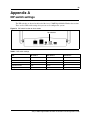
Appendix A
DIP switch settings . . . . . . . . . . . . . . . . . . . . . . . . . . . . . . . . . . . . . . . . . . . . 53
Appendix B
Wiring information . . . . . . . . . . . . . . . . . . . . . . . . . . . . . . . . . . . . . . . . . . . . . 55
Appendix C
NN40110-301
Contents
5
Button mapping . . . . . . . . . . . . . . . . . . . . . . . . . . . . . . . . . . . . . . . . . . . . . . . 57
Avaya 7406E Digital Mobile Handset Installation and Configuration Guide
6
Contents
NN40110-301
Task List
7
Task List
Navigating through programming mode menus ............................................................21
Installing the handset charging cradle ...........................................................................36
Installing the battery pack ..............................................................................................36
Charging the battery pack for the first time....................................................................37
Securing the base station mounting bracket .................................................................38
Connecting the telephone line and power adapter to the base station..........................38
Mounting the base station .............................................................................................38
Installing the external battery charger ...........................................................................38
Setting the base station DIP switches for a single-base station application ..................39
Setting the base station DIP switches for a two-base station application......................39
Assigning a port ID to a handset ...................................................................................40
Registering a handset....................................................................................................41
Deregistering one handset ............................................................................................42
Deregistering all the handsets .......................................................................................42
Resetting a handset.......................................................................................................43
Changing the maintenance password ...........................................................................43
Scanning the base station radio frequency ...................................................................45
Scanning the environment.............................................................................................46
Installing the USB-to-UART bridge controller drivers ....................................................47
Upgrading the base station firmware .............................................................................48
Upgrading the handset firmware ...................................................................................49
Verifying the firmware version .......................................................................................50
Avaya 7406E Digital Mobile Handset Installation and Configuration Guide
8
Task List
NN40110-301
9
Customer service
Visit the Avaya Web site to access the complete range of services and support that Avaya
provides. Go to www.avaya.com or go to one of the pages listed in the following sections.
Navigation
•
•
•
•
"Getting technical documentation" (page 9)
"Getting product training" (page 9)
"Getting help from a distributor or reseller" (page 9)
"Getting technical support from the Avaya Web site" (page 9)
Getting technical documentation
To download and print selected technical publications and release notes directly from the Internet,
go to www.avaya.com/support.
Getting product training
Ongoing product training is available. For more information or to register, you can access the Web
site at www.avaya.com/support. From this Web site, you can locate the Training contacts link on
the left-hand navigation pane.
Getting help from a distributor or reseller
If you purchased a service contract for your Avaya product from a distributor or authorized
reseller, contact the technical support staff for that distributor or reseller for assistance.
Getting technical support from the Avaya Web site
The easiest and most effective way to get technical support for Avaya products is from the Avaya
Technical Support Web site at www.avaya.com/support.
Avaya 7406E Digital Mobile Handset Installation and Configuration Guide
10
Customer service
NN40110-301
11
Chapter 1
New in this release
This is the first release of the Avaya 7406E Digital Mobile Handset. See the following sections for
information about features:
•
•
•
handset
— three-line LCD
— six programmable one-touch indicator keys
— choice of ring tones
— 20-name directory
— battery level indicator
base station
— wall- or ceiling-mountable
— colored LED status indicators
— security and encryption
— antenna diversity
USB to UART bridge controller
Handset features
This section describes some of the new Avaya 7406E Digital Mobile Handset features.
Three-line LCD
The LCD shows three rows of text, with a maximum of 16 characters in each row. The LCD also
supports the English, French, and Spanish menus. The LCD is back-lit to help with viewing under
low light conditions. For more information on the LCD, refer to the Avaya 7406E Digital Mobile
Handset User Guide (NN40110-110).
One-touch indicator keys
You can program the indicator keys with internal or external numbers for speed-dialing, or with
features. For more information on the how to program the one-touch indicator keys, refer to the
Avaya 7406E Digital Mobile Handset User Guide (NN40110-110).
Choice of ring tones
You can chose one of eight ring tones. For more information on ring tones, refer to the Avaya
7406E Digital Mobile Handset User Guide (NN40110-110).
Avaya 7406E Digital Mobile Handset Installation and Configuration Guide
12
Chapter 1 New in this release
20-name directory
You can store a maximum of 20 internal or external numbers in the handset directory. For more
information on the directory, refer to the Avaya 7406E Digital Mobile Handset User Guide
(NN40110-110).
Battery level indicator
The battery level indicator appears in the upper right-hand corner of the LCD. The battery level
indicator shows four levels of battery energy. The Low Battery message appears on the LCD
when there are between five and ten minutes of talking time remaining. When the battery reaches
this low energy level and you are using the handset, you hear a warning tone approximately every
40 seconds. To charge or top-up the battery, place the handset in the charging cradle. For more
information on the battery level indicator, refer to the Avaya 7406E Digital Mobile Handset User
Guide (NN40110-110).
Base station features
This section describes some of the new Avaya 7406E Digital Mobile Handset base station
features.
Wall- or ceiling-mountable
The base station comes with a mounting rack that you can use to attach the base station to the wall
or ceiling. For more information on how to mount the base station on the wall or ceiling, refer to
“Securing the base station mounting bracket” on page 40 and “Mounting the base station” on page
40.
Colored LED status indicators
The base station has five colored LED status indicators: one to show the status of the base station,
and four to show the statuses of the handsets (one for each possible handset that you can register to
a single base station). For more information about the LED status indicators, see “Base station
overview” on page 27.
Security and encryption
The handset security code is changed each time you place the handset in the charging cradle. Each
time you register a handset with the base station, 64-bit ETSI encryption is applied to the handset.
NN40110-301
Chapter 1 New in this release
13
Antenna diversity
The base station and each handset are equipped with two antennas. Dual antennas ensure better
reception by minimizing multipath fading effects. The base station antennas pivot to allow you to
position them in the most optimum direction. Adjust the antenna for optimal transmission by
moving it through 90-degree-angle planes (for example, perpendicular to the wall, parallel to the
wall, perpendicular to the floor, parallel to the floor).
USB to UART bridge controller
You can upgrade the Avaya 7406E Digital Mobile Handset firmware when new versions become
available. Use the USB to UART bridge controller, along with the FlashLoader program, to
upgrade the firmware. For more information on how to upgrade your Avaya 7406E Digital Mobile
Handset system, refer to Chapter 6, “Upgrading the firmware,” on page 49
Avaya 7406E Digital Mobile Handset Installation and Configuration Guide
14
Chapter 1 New in this release
NN40110-301
15
Chapter 2
Introduction
The following topics are covered in this chapter:
•
•
•
•
•
•
•
•
•
•
Specifications
Installation considerations
Handset overview
Handset features
Programming mode menus
Battery pack overview
Base station overview
Additional components
Battery charge controller
Firmware upgrade components
The Avaya 7406E Digital Mobile Handset connects to the Avaya KSU. Up to four lines run from
the KSU to the Avaya 7406E Digital Mobile Handset base station. Each base station, of which
there can be a maximum of two within 10 meters of each other, can accommodate a maximum of
four handsets. The handset IDs (1, 2, 3, 4) correspond to lines 1, 2, 3, and 4 from the KSU.
The handset features are easy to set up using the function key and menus.
Specifications
The Avaya 7406E Digital Mobile Handset is a frequency-hopping spread spectrum (FHSS)
cordless telephone. The base station connects to the Avaya KSU (Avaya Norstar, CICS and MICS,
and Avaya Business Communications Manager (Avaya BCM) systems). The benefits of this
technology are: improved range, robustness, and less susceptibility to interference, fading, and
multipath. The following table highlights the main physical specifications of the Avaya 7406E
Digital Mobile Handset equipment.
Frequency band
2.4 GHz ISM band
Total channel capability
Frequency-hopping spread spectrum (FHSS) available on 90 channels for
each base.
Handset dimensions
Length: 140 mm (5.5 in.)
Width: 57 mm (2.25 in.)
Overall thickness: 40 mm (1.60 in.)
Channel spacing
864 KHz
Time slots
4 transmit and 4 receive time slots
Handset range
350 m (1000 ft), for outdoor direct line-of-sight
Avaya 7406E Digital Mobile Handset Installation and Configuration Guide
16
Chapter 2 Introduction
Handset weight
280 g/9.38 oz. (with battery pack)
Battery pack
Capacity: 700 mAh, 3.6 V
Standby mode: up to 36 hours
4 to 5 hours of talk time
Base dimensions
Length: 150 mm (6 in.)
Width: 160 mm (6.4 in.)
Height (front): 28 mm (1.12 in.)
Height (rear): 34 mm (1.36 in.)
Base power
Input: 110 VAC, 60 Hz
Output: 9 VDC, 850mA
Installation considerations
The Avaya 7406E Digital Mobile Handset is a cordless telephone system that allows you to freely
move around your work space while on a call, and still maintain access to the telephone system
features available to you.
The Avaya 7406E Digital Mobile Handset uses advanced digital FHSS technology to provide a
quality audio path over a 2.4 GHz radio link.
Note: The Avaya 7406E Digital Mobile Handset cordless telephone is supported
on all Avaya Norstar systems (DR3 or higher) and on all Avaya BCM Systems.
The use of a wall-mounted base station allows you to position the base antennas for maximum
performance and coverage. The indoor range of the Avaya 7406E Digital Mobile Handset varies
based on the type of office environment. The outdoor clear-line-of-sight range is 350 meters (1000
feet). This range can vary with differing environments.
Operational bandwidths
The Avaya 7406E Digital Mobile Handset operates in the Industrial, Scientific, and Medical (ISM)
2.4 GHz band.
Radio frequency local area networks
Radio frequency local area networks (RF LAN) are primarily installed in large chain businesses,
such as retail and grocery, where the RF LAN is used for inventory equipment.
With the correct selection of the Avaya 7406E Digital Mobile Handset operating band, the RF
LAN operating at 2.4 GHz does not pose an operating issue for Avaya 7406E Digital Mobile
Handset, nor does the Avaya 7406E Digital Mobile Handset pose issues for the RF LAN with
respect to data transmission capabilities. However, there can be instances where the Avaya 7406E
Digital Mobile Handset user can hear an occasional audio click when operating in an RF LAN
environment. This should not inhibit the user's ability to hold a normal two-way conversation
using the Avaya 7406E Digital Mobile Handset.
NN40110-301
Chapter 2 Introduction
17
Operational parameters
For a configuration of eight handsets, you need two base stations. Each base station supports a
maximum of four handsets.
Telephone-to-base range
The Avaya 7406E Digital Mobile Handset cordless telephone utilizes an extremely efficient radio
design to deliver the maximum possible range while complying with the governing rules of the
Federal Communications Commission (FCC) and Industry Canada. The effective operating range
within a site largely depends on the environmental characteristics, such as building construction
and internal layout of the site. The indoor range of the Avaya 7406E Digital Mobile Handset varies
based on the type of office environment. The outdoor clear-line-of-sight range is 350 meters (1000
feet). This range can vary with differing environments.
If the Avaya 7406E Digital Mobile Handset does not meet this operating range, try the following
troubleshooting activities:
•
•
•
•
•
Check surroundings for any other product that can cause interference.
Check the environment for obstructions that can limit the range.
Change the orientation of the base station antenna.
Move the base station to another location.
Select the alternate operating band of the Avaya 7406E Digital Mobile Handset.
Based on environmental characteristics, the Avaya 7406E Digital Mobile Handset may not be the
optimum solution for all users. If the desired level of mobility performance is not met, contact your
authorized Avaya distributor to discuss alternatives.
Radio range and coverage considerations
The effective operating radio range in your facility depends on the building construction and the
internal layout of the facility. An open office environment enhances operating radio ranges.
Density and interference
For this system to be interference-free, install a maximum of two base stations and eight handsets
per location. Each base station provides four independent time-compression multiplexing (TCM)
line connections to the telephone system.
Installation site parameters
To maximize the performance of the Avaya 7406E Digital Mobile Handset, evaluate the physical
characteristics of the site prior to determining the location of the base station installation. Consider
the following common characteristics:
•
•
wood versus metal construction
metal versus wood studs in wall construction
Avaya 7406E Digital Mobile Handset Installation and Configuration Guide
18
Chapter 2 Introduction
•
•
•
•
•
thickness of concrete floors and walls (and type of covering, for example metallic wall paper)
number of floors and walls
open office (cubicles) versus closed office (floor to ceiling)
steel partitions, elevator shafts, electric utility rooms
radio frequency local area networks (RFLAN), extensive machinery, computer equipment, and
other cordless phones or wireless devices
Place the antenna correctly to endure that the performance of the Avaya 7406E Digital Mobile
Handset is at its best. Pick a central location and mount the antenna using the following guidelines:
•
•
•
•
•
•
•
In a two-base-station installation, space the base stations a minimum of 10 meters apart, and a
minimum of 10 meters from any other 2.4 GHz wireless equipment.
Attach the base station a minimum of eight feet from the floor.
Minimize the number of walls between the base station and handsets.
Centralize the location of the base station to make the number of interfering walls equal in all
directions.
Do not mount the base station on an outside wall.
Do not mount or place the base station outdoors.
Adjust the antenna for optimal transmission by moving it through 90-degree-angle planes (for
example, perpendicular to the wall, parallel to the wall, perpendicular to the floor, parallel to
the floor).
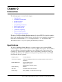
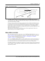
Environment layout considerations
The following facility layouts are examples of reference building footprints for which the Avaya
7406E Digital Mobile Handset is most suited.
Storefronts
This layout has fewer than 929 square meters (10 000 square feet) of floor space. This layout has
open environments with few interior barriers
30.5 m (100 ft)
30.5 m
(100 ft)
NN40110-301
Diagonal
measurement is
44 m (144 ft)
46 m(150 ft)
46 m
(150 ft)
Diagonal
measurement is
55 m (180 ft)
Chapter 2 Introduction
19
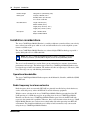
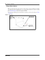
Office facilities
46 m (150 ft)
46 m
(150 ft)
The Avaya 7406E Digital Mobile Handset can also be
used in business premises with larger square footage
and that have an interior layout that has a higher
concentration of physical barriers. Full radio
coverage at these facilities takes more planning to
work around possible barriers.
A professional office
• is typically less than 2 323 square meters (25 000
square feet) in size
• is typically a mix of open and closed offices
• has an office floor with an elevator shaft and utility
rooms in the core facility
Some transmission path loss occurs when the base station and the handset are separated by
physical barriers, as represented by this core area.
The amount of path loss is depends on the number of walls, type of material, and density of
barriers used in the core area.
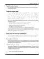
Combination office/warehouse
30.5 m
(100 ft)
61 m
(200 ft)
• Various small businesses
• Typically under 1 394 square meters (15 000 square
feet)
• Mixture of closed offices and open spaces
Typical facility with both office and warehousing
combined in one operation.
Some transmission path loss in expected with the
presence of dense firewall and racking or shelves
filled with dense materials. Consider placing base
station in largest room.
Range is limited in this situation.
Avaya 7406E Digital Mobile Handset Installation and Configuration Guide
20
Chapter 2 Introduction
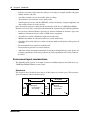
Office with adjacent yard area(s)
95 m
(300 ft)
• Various small businesses
• are typical office facilities with 465 to 929 square
meters (5 000 to 10 000 square feet) of floor space
• have adjacent open space or a yard next to office
•radio transmission is relatively unimpaired in more
open environments because there are fewer path
losses caused by barriers, such as walls
This environment can allow for
base-station-to-handset ranges in excess of 95 m
(300 feet).
Unsuitable environments
Large campuses (business sites with more than one building) are not a suitable application for the
Avaya 7406E Digital Mobile Handset.
For this type of environment, contact your authorized Avaya distributor to discuss alternatives.
Handset overview
The Avaya 7406E Digital Mobile Handset handset automatically links with the base station by
searching for the base station signal after you complete following tasks:
•
•
•
charge the battery
power the base station and handset
configure the handset identification
Monitoring handset signal strength
When you move too far from the base station, the following occurs on the handset:
•
•
•
the Out of range... message appears
the handset produces an intermittent beep
the handset goes into scanning mode
Move back into range of the base station to stop the handset display messages and warning tones.
If you go out of range during an active call, the call is automatically placed on hold. Press the
flashing red line button to retrieve a held call when you are back in range of the base station. In
cases when the line button does not light up when you move back into range of the base station,
press the intercom/line button that the call came in on to take the call off hold
NN40110-301
Chapter 2 Introduction
21
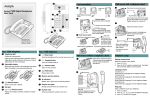
Handset features
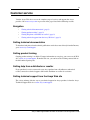
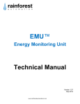
Figure 1 on page 22 shows the layout of the handset function keys, softkeys, and keypad, as well
as additional handset features.
Avaya 7406E Digital Mobile Handset Installation and Configuration Guide
22
Chapter 2 Introduction
Figure 1 Handset features
Call-hold/message
waiting indicator
Flashes when a call is on hold
or when a message is waiting.
LCD
Indicator keys
Shows the call information and
handset status icons, and guides
you while using features.
Start or cancel a
feature.
Soft keys
Use in Programming mode to
scroll through menus and options.
Handsfree/speaker phone
Release key
Cancels active
calls.
Hold
Places an active call on hold.
Feature key
Activates the Feature functions.
Volume control
Func key
Dial pad
Microphone
Use to access
programming mode
or to answer a call.
Belt clip notches
Headset port
Battery Pack
NN40110-301
Chapter 2 Introduction
23
Indicator keys
You can program each of the six indicator keys as one-touch dialing keys or as feature keys. Each
of the six indicator keys is preprogrammed as shown in Table 1.
Table 1 Indicator key map
Left-hand keys
Setting
Right-hand keys
Setting
Top
Do Not Disturb
Top
Last Number
Middle
Make Call First
Middle
Talk Mode (Dial Voice Call)
Bottom
Forward To
Bottom
Talk Mode
Dial pad character mapping
You can use the dial pad to enter numbers and characters in the directory. To enter the first
character on a key, press the appropriate dialpad key once. To enter the second character on a key,
press the appropriate dialpad key twice, and so on for subsequent characters and numbers. See
Table 2 for a character map of the dialpad.
Table 2 Dial pad character map
1
,-‘&()@!1
2
ABCabc2
3
DEFdef3
4
GHIghi4
5
JKLjkl5
6
MNOmno6
7
PQRSpqrs7
8
TUVtuv8
9
WXYZwxyz9
*
*
0
0 space
#
#
Programming mode menus
The following table maps the menu items and options available when the phone is in system
programming mode.
Navigating through programming mode menus
Complete this procedure to learn how to scroll up and down through the main menu, and up and
down through menu options.
1
Press the Func key to enter system programming mode.
The main menu appears.
2
Use the ï ï , ïïïïïï , and ïïï ï softkeys to scroll through the main menu.
3
At any menu level, press the Release key to return to the previous menu level.
4
At any menu level, press the Release key again to exit system programming mode.
Avaya 7406E Digital Mobile Handset Installation and Configuration Guide
24
Chapter 2 Introduction
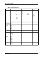
Table 3 Programming mode menus
Main menu
Submenu 1
Directory
List
Up
Submenu 2
Submenu 3
Edit
Back
Name
Next
Dial
Down
Add
Bksp
Save
Space
Down
Key Lock?
Key locked
Key unlock?
Message LED
On
Off
Back Light
60sec
50sec
40sec
30sec
20sec
10sec
Off
Key Beep
Off
On
Ring/Vibration
Ring On
Both Off
Both On
Vibration On
Ring Type
Type-1
Type-2
Type-3
Type-4
Type-5
Type-6
Type-7
Type-8
Ring Level
High
Medium
Low
NN40110-301
Select
Submenu 4
Back
Number
Next
Submenu 5
Back
Remove
Done
Chapter 2 Introduction
25
Table 3 Programming mode menus
Main menu
Submenu 1
Default Volume
Level-8
Level-7
Level-6
Level-5
Level-4
Level-3
Level-2
Level-1
No Default
Noisy Location
Level-1
Level-2
Level-3
Level-4
Display Battery
Voltage Level
Maintenance
Enter Pswd
Submenu 2
Submenu 3
Assign Port ID
1
2
3
4
Registration
No?
Yes?
Scan Base RF
No?
Yes?
Scan Environ
No?
Yes?
De-Registration
HS
No?
Yes?
Change PSW
Enter New
Password
Reset Handset?
No?
Yes?
Submenu 4
Submenu 5
Battery pack overview
The Avaya 7406E Digital Mobile Handset design is a reliably-powered cordless business
telephone that uses premium 700- mAh NiMh batteries (rechargeable nickel metal hydride
battery).
Before you use the Avaya 7406E Digital Mobile Handset, read the following information:
•
•
Install and charge the Avaya 7406E Digital Mobile Handset battery pack (see Chapter 3,
“Installing the base telephone equipment,” on page 37).
You must fully charge the rechargeable battery pack before you use the Avaya 7406E Digital
Mobile Handset for the first time.
Avaya 7406E Digital Mobile Handset Installation and Configuration Guide
26
Chapter 2 Introduction
•
•
•
•
Do not use the nickel metal hydride batteries provided with your Avaya 7406E Digital Mobile
Handset with any other product. These batteries are designed specifically for use with the
Avaya 7406E Digital Mobile Handset and charger only. Improper use of the Avaya 7406E
Digital Mobile Handset batteries can result in a fire hazard.
Do not charge the battery with any charger other than the one supplied with this equipment.
You must dispose of nickel metal hydride batteries properly.
Do not dispose of the batteries in office or household waste.
Warning: Risk of explosion
Do not expose the battery pack to fire. The batter pack can explode if you try to dispose of
in or expose it to a fire.
You can recycle nickel metal hydride batteries. You can help preserve the environment by
returning your unwanted batteries to your nearest recycling center for recycling or proper disposal.
A fully charged battery can provide approximately four to five hours of talk time and has a
three-year service life.
The Avaya 7406E Digital Mobile Handset meets the following talk-time parameters:
•
•
•
•
You can use the handset for an entire eight-hour work day without putting it into the charger
cradle for charging or topping up.
You can use a handset with a fully-charged battery for four to five hours of talk time.
Most users do not use more than three hours of talk time in an average eight-hour work day.
If talk time exceeds four hours, or if you use the handset through multiple, consecutive shifts,
ensure you have multiple spare batteries on hand.
The Avaya 7406E Digital Mobile Handset meets the following standby parameters:
•
•
•
You can have the handset, with a fully-charged battery, in standby mode for up to 36 hours.
If the phone is in standby mode, the low-battery status is not indicated.
You can perform most configurations only when the handset is in the standby mode.
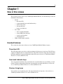
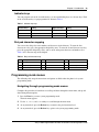
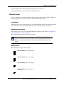
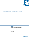
External battery charger
The 240mA external battery charger allows you to charge two battery packs at the same time,
while a third battery pack is in the handset. The external battery charger has two slots for the
battery packs, as shown in Figure 2 on page 27.
NN40110-301
Chapter 2 Introduction
27
Figure 2 External battery charger
Dual charging slots
Front slot LED
Rear slot LED
Two LEDs, marked 1 and 2, are associated with the two slots. The LEDs light up when the
associated slot is active. When you connect the battery charger to a power source, the Avaya logo
at the front of the charger is backlit.
To charge a battery pack, insert the battery pack into one of the available slots. When the battery
pack is properly inserted, the corresponding LED flashes for two seconds to indicate whether or
not the battery is accepted. If the battery is dead, the red LED flashes. The flashing red LED
indicates that the battery is not suitable for charging. If the battery is good, the LED flashes red to
indicate that charging is in process.
When the battery is fully charged, the LED turns green. It takes approximately 5 hours for a
depleted battery pack to be completely recharged.
Base station overview
This section illustrates the base station for the Avaya 7406E Digital Mobile Handset system (see
Figure 3 on page 28). You can mount the base station on a wall or on the ceiling, or place it on a
flat surface without the mounting bracket. See Chapter 3, “Installing the base telephone
equipment,” on page 37 for installation procedures.
The Avaya 7406E Digital Mobile Handset cordless telephone operates on the same principle as a
two-way radio. The location of the base station affects the range of reception. Do not install the
base station where radio waves are blocked or reflected, such as next to a filing cabinet.
For optimal performance, install the base station at least 2.4 meters (eight feet) above the floor and
at least 10 meters (34 feet) apart from a second base station. Always position the antennas at a 90°
angle to the base station.
Avaya 7406E Digital Mobile Handset Installation and Configuration Guide
28
Chapter 2 Introduction
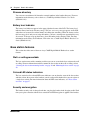
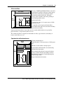
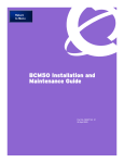
Base station features
When you connect the power source to the base station, the base station status LED starts flashing
green. During operation, the LED flashes every second to indicate that the base station is receiving
power. Figure 4 on page 29 shows the location of the LEDs.
You can use the mounting bracket to install the base station on a wall or on the ceiling (see Figure
5 on page 29).
Figure 3 Base station
Base station
antennas
(90° to base
station)
LED indicates base
station has power
LEDs indicate
handset status
NN40110-301
Chapter 2 Introduction
Figure 4
29
Base station LEDs
Power LED
Channel LEDs
Figure 5 Base station with mounting bracket
Mounting
bracket
Notches match to bracket.
Avaya 7406E Digital Mobile Handset Installation and Configuration Guide
30
Chapter 2 Introduction
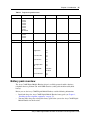
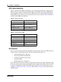
LED status indicators
The base station has five LED status indicators: one to show the status of the base station (power
LED), and one for each of the four possible handsets (channel LEDs). The power LED indicates
the current mode of the base station. The power LED is green and is either solid or flashing. The
channel LEDs are tri-color (red, green, and orange) and are always solid. See Table 4 and Table 5
for details on the LED status indicators.
Table 4 Power status LED
Status
Cadence
Active
1 second on, 1 second off
Registration mode, power on,
initializing
125 ms on, 125 ms off
Deregistration mode
500 ms on, 500 ms off
No handset
Solid
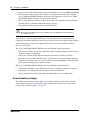
Table 5 Channel status LEDs
Status
Color indicators
Line not connected
Off
Line initializing
Orange
Line idle
Green
Line ringer on
Red
Line ringer off
Green
Line talk
Red
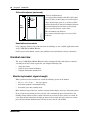
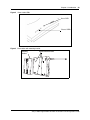
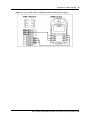
DIP switches
The base station is designed with a three-bit DIP switch panel at the back. Use the DIP switches to
change the base station operation mode. The base station operation modes are:
•
•
•
•
•
normal operating mode—full band
band A (for optional two-band setup)
band B (for optional two-band setup)
registration mode
deregistration mode—all handsets
If you install two base stations, and there is interference between the two when in normal operating
most, you can set one base station to operate in the band A (upper band) and the other base station
to operate in band B (lower band). For the DIP switch settings for each operating mode, refer to
Appendix A, “DIP switch settings,” on page 53. Figure Figure 6 on page 31 show the location of
the DIP switches.
NN40110-301
Chapter 2 Introduction
31
Figure 6 Back of base station showing DIP switches
DIP switches
Wiring charts
For information how to wire the Avaya 7406E Digital Mobile Handset to your system, refer to
Appendix B, “Wiring information,” on page 55.
Avaya 7406E Digital Mobile Handset Installation and Configuration Guide
32
Chapter 2 Introduction
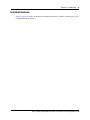
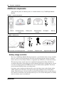
Additional components
Along with this guide, the following items are included with the Avaya 7406E Digital Mobile
Handset.
Figure 7 Handset components
Handset
Handset charging
cradle
Battery pack
External battery
charger
AC adapter
Belt clip
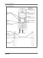
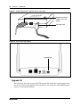
Figure 8 System parts
Upgrade
ToPC
-
+
Mounting bracket
Base station and mounting bracket
AC adapter
Telephone cord
Upgrade bridge controller
Battery charge controller
The Avaya 7406E Digital Mobile Handset incorporates a special handset battery charge controller
that uses a four-stage charging program. The four-stage charging program sequences charging
from a soft start to a fast charge, and then to a topping charge, followed by a maintenance charge.
This four-stage charge sequence presents an optimum-charging plan that helps maximize the
overall life of the battery by managing two critical elements in the battery charging process: charge
rate and overcharging protection. NiMh batteries do not exhibit memory problems. You do not
need to drain the batteries before you recharge them.
Low battery status is indicated on the handset by the visual charge status on the display and the
audible warning tone. The battery icon appears in the upper right-hand corner of the handset
display. When the battery is low, the battery icon flashes. If the handset is in use and the battery is
low, the battery icon flashes and a warning tone beeps every 15 seconds. If the phone is in standby
mode, low battery status is not indicated.
NN40110-301
Chapter 2 Introduction
33
Place the handset in the charge cradle for charging when it is not in use.
A fully depleted battery is restored to full charge in three hours.
Handset power
Power to the handset comes from the battery pack installed in the back of the handset. When the
battery pack power level is low it must be recharged in the charging cradle.
Low battery
When the power is low, a tone sounds every 15 seconds indicating you need to recharge the battery
soon. Your call is automatically put on hold 20 seconds after the battery pack runs out.
Recharging the battery
Recharging begins as soon as you put the handset in the charging cradle. Refer to "Charging the
battery pack for the first time" (page 39).
Be sure that the handset and charger contacts touch.
Note: If you do not correctly install the Avaya 7406E Digital Mobile Handset
battery, or if the battery level is extremely low, the six programmable buttons can
light or flash simultaneously. This can also happen when the handset is in the
charger.
Battery levels
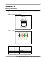
The following icons appear on the display.
Indicates battery pack is fully charged.
Indicates battery pack is 2/3 charged.
Indicates battery pack is 1/3 charged.
Indicates battery pack is completely
discharged.
Avaya 7406E Digital Mobile Handset Installation and Configuration Guide
34
Chapter 2 Introduction
Firmware upgrade components
To upgrade the firmware on the Avaya 7406E Digital Mobile Handsets and on the base station, or
base stations, you need the following components and materials:
•
•
•
•
USB-to-UART bridge controller
Handset adapter
Upgrade cables
Upgrade CD
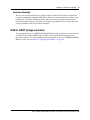
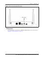
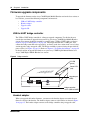
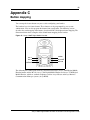
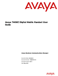
USB-to-UART bridge controller
The USB-to-UART bridge controller is a firmware upgrade component. Use this hardware to
transfer the new firmware upgrade from your PC to your Avaya 7406E Digital Mobile Handset
system. You connect the bridge controller to your PC using a USB-to-UART cable (see figures
Figure 9 on page 34 and Figure 11 on page 36). The bridge controller has a UART port. You
connect the bridge controller to the upgrade jig, or directly to the base station in the case of a base
station upgrade, using an upgrade cable. The bridge controller is powered using the provided AC
power source (see Figure on page 34). Refer to Chapter 6, “Upgrading the firmware,” on page 49
for details on how to upgrade the firmware on your Avaya 7406E Digital Mobile Handset and
Avaya 7406E Digital Mobile Handset base station.
Figure 9 Bridge controller
PC LED
(green)
Power LED
(red)
Upgrade port
(USB)
Upgrade
ToPC
-
+
Bridge controllerto-PC (USB-to-UART)
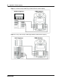
Handset adapter
When you upgrade the handset firmware, you must use the handset adapter to transfer the new
firmware version to the handset. The handset adapter connects to the handset as shown in Figure
10 on page 35. The handset adapter connects to the bridge controller using an upgrade cable.
NN40110-301
Chapter 2 Introduction
35
Figure 10 Handset adapter
Spring-loaded clips
Handset adapter
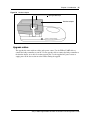
Upgrade cables
The upgrade kit comes with two cables and a power source. Use the USB-to-UART cable to
connect the bridge controller to your PC. Use the upgrade cable to connect the bridge controller to
the handset adapter, or to the base station upgrade port. Use the supplied AC power source to
supply power to the base station or to the handset during the upgrade.
Avaya 7406E Digital Mobile Handset Installation and Configuration Guide
36
Chapter 2 Introduction
Figure 11 Bridge controller with upgrade cable and AC power
Upgrade to handset
adapter or to base
station
Upgrade
ToPC
-
AC power cord
+
Figure 12 Base station upgrade port
Upgrade port
Upgrade CD
The upgrade kit comes with an upgrade CD. The upgrade CD contains the required upgrade device
drivers (one for the handset upgrade and one for the base station upgrade), the FlashGUI upgrade
interface, and the upgrade firmware.
NN40110-301
37
Chapter 3
Installing the base telephone equipment
Complete the following procedures to install the Avaya 7406E Digital Mobile Handset system
equipment:
•
•
•
•
•
•
Installing the handset charging cradle
Installing the battery pack
Charging the battery pack for the first time
Securing the base station mounting bracket
Connecting the telephone line and power adapter to the base station
Mounting the base station
Important first-time installation information
When performing the initial configurations on the handset, ensure that all the handsets you intend
to configure have fully-charged battery packs installed.
Because the handsets start scanning as soon as they are powered, you must set the handset IDs
before you configure the handset to avoid conflicts between handset signals and the possibility of
one set mirroring another.
For information on wiring your system, refer to Appendix B, “Wiring information,” on page 55.
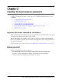
Before you start
Before you install the base station, ensure that
•
•
•
the telephone lines from your system have been installed at the base station location
there is an ac power outlet within 1.5 meters (5 feet) of the base station location
you have removed the mounting bracket from the base station
Avaya 7406E Digital Mobile Handset Installation and Configuration Guide
38
Chapter 3 Installing the base telephone equipment
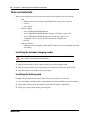
Tools and materials
Before you install the base station, ensure that you have the following tools and materials:
•
•
•
tools
— Phillips or flat-head screwdriver, depending on the type of screws you have
— 2 screws
— pen or pencil
package contents
— Avaya 7406E Digital Mobile Handset
— Avaya 7406E Digital Mobile Handset charging cradle and ac power cord
— Avaya 7406E Digital Mobile Handset base station and ac power cord
— 1 telephone cable to connect the base station to the telephone jack
— belt clip
additional material
— additional customer-supplied cables for RJ45 connector if you are installing more than
one handset
Installing the handset charging cradle
Warning: You must complete the steps in this section when you first initialize a
base station and configure the first handset.
1
Plug the small end of the power adapter into the back of the charging cradle.
2
Plug the other end of the power adapter into an AC outlet near the location of the cradle.
3
Place the handset in the cradle to charge the battery.
Installing the battery pack
Complete this procedure if the battery pack is not already installed in your handset.
1
Use your thumb to slide the battery compartment cover down and off the back of the handset.
2
Position the battery pack in the bottom position inside the battery compartment.
3
Firmly press the top of the battery pack into place.
NN40110-301
Chapter 3 Installing the base telephone equipment
4
39
Replace the battery compartment cover.
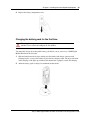
Charging the battery pack for the first time
Warning: It is imperative that you follow the steps in this section when you first
initialize a base station and configure the first handset.
You must fully charge the rechargeable battery pack before you use your Avaya 7406E Digital
Mobile Handset for the first time.
1
Slide the handset into the charger, making sure the handset and charger contacts touch.
Charging begins as soon as the handset is placed in the charging cradle. The logo at the front
of the charging cradle lights up to indicate that the handset is properly seated and charging.
2
Allow the battery pack to charge for a minimum of three hours.
Avaya 7406E Digital Mobile Handset Installation and Configuration Guide
40
Chapter 3 Installing the base telephone equipment
Securing the base station mounting bracket
Complete this procedure if you plan to mount the base station on a wall or ceiling. Skip this
procedure if you plan to place the base station on a flat surface.
1
Place the mounting bracket against the wall or ceiling where you want to install the base
station.
2
Use the mounting bracket as a template to position the base station and to mark the screw
positions.
3
Use the four screws to attach the mounting bracket to a wall or ceiling.
Connecting the telephone line and power adapter to the base
station
1
For a single handset installation, plug one end of the line cord into the telephone jack on the
base station labeled TCM1. For a multiple-handset installation plug the line cord into the jack
labeled TCM1-4.
If you are connecting more than one handset to the base station, you cannot connect any
handset to the TCM1 jack. You must connect all TCM lines to the TCM1-4 jack.
2
Connect the other end of the line cord into a telephone port on the system equipment.
For wiring information, refer to Appendix B, “Wiring information,” on page 55.
3
Plug the small end of the power adapter into the back of the base station.
4
Plug the other end of the power adapter into an AC outlet near the location of the base station.
Mounting the base station
Complete this procedure if you plan to mount the base station on a wall or ceiling. Skip this
procedure if you plan to place the base station on a flat surface.
1
Align the notches on the back of the base station with the mounting bracket on the wall or
ceiling.
2
Push the base station against the brackets until they are securely connected.
3
Adjust the antennas on the base station for optimal signal reception.
For the best radio reception, make sure the antenna on the base station are always vertical.
Installing the external battery charger
1
Plug the small end of the power adapter into the back of the battery charger.
2
Plug the other end of the power adapter into an AC outlet near the location of the charger.
3
Place one or two battery packs in the charger.
The red LED for each battery pack slot flashes to indicate that the battery is charging. The
Avaya logo lights. The LEDs turn green when the battery packs are fully charged.
NN40110-301
41
Chapter 4
Registering, deregistering, and resetting the
Avaya 7406E Digital Mobile Handset
This chapter provides procedures for registering the Avaya 7406E Digital Mobile Handset system.
Complete the following procedures in the order in which they are provided to register handsets:
•
•
•
•
•
•
•
•
Setting the base station DIP switches for a single-base station application
Setting the base station DIP switches for a two-base station application
Assigning a port ID to a handset
Registering a handset
Deregistering one handset
Deregistering all the handsets
Resetting a handset
Changing the maintenance password
Registration requirements
The following details the registration requirements for the base station in four different modes.
•
•
Registration mode: Allows the base station to permanently stay in a Registration mode.
Normal operational mode: Allows the base station to be in Registration mode for the first
30 seconds of operation and then the base station returns to Normal mode (no registrations
after 30 seconds)
If the user wants to use a handset in Normal mode, then the handset must be registered to
the base in Normal mode. Once completed successfully, there is no registration issue after
the base has been power cycled, providing the dip switch settings are not rearranged.
•
A-Group mode: Allows the base station to be in Registration mode for the first 30
seconds of operation and then the base station returns to A-Group mode (no registrations
after 30 seconds)
If the user wants to use a handset in A-Group mode, then the handset must be registered to
the base in A-Group mode. Once completed successfully, there is no registration issue
after the base has been power cycled, providing the dip switch settings are not rearranged.
•
B-Group mode: Allows the base station to be in Registration mode for the first 30
seconds of operation and then the base station returns to B-Group mode (no registrations
after 30 seconds)
If the user wants to use a handset in B-Group mode, then the handset must be registered to
the base in B-Group mode. Once completed successfully, there is no registration issue
after the base has been power cycled, providing the dip switch settings are not rearranged.
Avaya 7406E Digital Mobile Handset Installation and Configuration Guide
42
Chapter 4 Registering, deregistering, and resetting the Avaya 7406E Digital Mobile Handset
Setting the base station DIP switches for a single-base station
application
Refer to Appendix A, “DIP switch settings,” on page 53” for the correct settings for each mode.
1
Locate the base station DIP switches at the back of the base station.
2
Set the DIP switches to normal operating mode.
Setting the base station DIP switches for a two-base station
application
If you install two base stations, and there is interference between the two when in normal operating
most, you can set one base station to operate in the band A (upper band) and the other base station
to operate in band B (lower band). For the DIP switch settings for each operating mode, refer to
Appendix A, “DIP switch settings,” on page 53.
1
Locate the base station DIP switches at the back of the first base station.
2
Set the DIP switches to normal operating mode for a two-base station application—base
station A.
3
Locate the base station DIP switches at the back of the second base station.
4
Set the DIP switches to normal operating mode for a two-base station application—base
station B.
The base stations each now operate in one half of the ISM band.
Assigning a port ID to a handset
You cannot assign the same port ID to two handsets. If you assign a handset a port ID that is
already used by a second handset, the new handset registers with that port ID and that information
is discarded from the second handset.
A single handset can only have one port ID. If you assign a new port ID to a handset, the original
port ID and registration information clears from the handset. The handset loses its link to the base
station to which it was originally registered.
Before you register handsets, you must assign a unique port ID to each handset that you intend to
register with the base station.
1
When the phone is in standby mode, press the Func key.
The phone enters System Programming mode.
2
Use the up and down softkeys to navigate to the Maintenance menu.
3
Press Select.
You are prompted to enter a password.
4
Use the number keys to enter the maintenance password. To correct an error in the password,
press Delete to backspace.
NN40110-301
Chapter 4 Registering, deregistering, and resetting the Avaya 7406E Digital Mobile Handset
43
The default password is 000000. To change the default password, see "Changing the
maintenance password" (page 46).
5
Press Select.
If you enter the password incorrectly, the message Failed! Try Again! appears on the
LCD. You return to the top of the Maintenance menu. Re-enter the password. If the password
is correct, the message OK! appears on the LCD, and you enter maintenance operation mode.
6
Use the up and down softkeys to navigate to the Assign Port ID option.
7
Press Select.
8
Use the up and down softkeys to navigate to the port ID you want to assign (1, 2, 3, or 4).
9
Press Select to save the new port ID for the handset.
The LCD displays the OK! message and returns to the top of the Maintenance menu.
Avaya 7406E Digital Mobile Handset Installation and Configuration Guide
44
Chapter 4 Registering, deregistering, and resetting the Avaya 7406E Digital Mobile Handset
Registering a handset
You must assign the port ID to the handset before you can register the handset. If you do not assign
a port ID to the handset first, the Please Register! message appears on the LCD. Make sure
the base station is in idle mode and the handsets are in idle mode before you start this procedure.
You must pair the handsets with a base station by registering the handsets. When you register a
handset, you establish a link between that handset and the base station. Registering a handset
prevents illegal use of or interception of conversations on the handset. Each time you register a
handset with the base station, the system generates a random secret code and sends it to that
handset.
Caution: Risk of service disruption
Always make sure that there are no TCM lines connected between the KSU and
the base station when the base station is in registration mode, or when you are
registering a handset.
Refer to Appendix A, “DIP switch settings” for the correct DIP switch settings.
1
Remove the power cord from the back of the base station.
2
Set the DIP switches at the back of the base station to registration mode.
If you do nothing with the handset for more than 30 seconds when the system is in registration
mode, the system returns automatically to normal operation mode without you having to
change the DIP switches.
3
Log on to the Maintenance menu.
4
Use the up and down softkeys to navigate to the Registration option.
5
Press Select.
6
Use the up and down softkeys to navigate to the Yes option.
7
Press Select to register the phone.
The Please Wait! message appears on the LCD.
8
Plug the power source back into the base station.
The base station power LED blinks rapidly.
9
After 5 seconds, the base station enters registration mode.
10 Place the handset near the base station.
If you successfully registered the handset the Registered! message appears in the LCD. If
you did not register the handset successfully, the Failed! Try Again! message appears.
Repeat steps 1 through 10.
You return to the top of the Maintenance menu.
11 Remove the power source from the base station.
NN40110-301
Chapter 4 Registering, deregistering, and resetting the Avaya 7406E Digital Mobile Handset
45
12 Set the DIP switches to normal operation mode if you are finished registering handsets with
the base station. Otherwise, repeat steps 1 through 10 for remaining unregistered handsets.
The base station status LED flashes normally once you set the base station back to normal
operation mode.
13 Plug the power source back into the base station.
14 Power cycle the base station.
Deregistering one handset
Make sure the base station is in idle mode, the handset is in standby mode, and that you have
removed power to the base station before you start this procedure.
Registered handsets lose their registration with a base station even when the power connector is
disconnected from the base station.
Refer to Appendix A, “DIP switch settings” for the correct DIP switch settings.
1
Log on to the Maintenance menu.
2
Use the up and down softkeys to navigate to the De-Registration option.
3
Press Select.
4
Use the up and down softkeys to navigate to the Yes option.
5
Enter the port ID that is assigned to the handset.
6
Press Select.
7
Press OK.
The set is now registered.
Deregistering all the handsets
Make sure the base station is in idle mode, the handsets are in standby mode, and that you have
removed power to the base station before you start this procedure.
Registered handsets lose their registration with a base station even when the power connector is
disconnected from the base station.
Refer to Appendix A, “DIP switch settings” for the correct DIP switch settings.
1
Remove the power source from the base station.
2
Set the DIP switches to deregistration mode.
3
Plug the power source back into the base station.
4
After several seconds, the base station enters deregistration mode.
All handsets are deregistered from the base station. Handsets cannot link to the base station.
5
Place all handsets near the base station.
All deregistered handsets return to nonregistered mode. The Please Register! message
appears on the LCD.
Avaya 7406E Digital Mobile Handset Installation and Configuration Guide
46
Chapter 4 Registering, deregistering, and resetting the Avaya 7406E Digital Mobile Handset
6
Remove the power source from the base station.
7
Set the DIP switches to normal operation mode.
8
Plug the power source back into the base station.
9
Power cycle the base station.
Resetting a handset
Reset the handset to revert settings and status to their original defaults. Ensure the handset is in
standby mode before you start this procedure.
1
In System Programming mode, use the up and down softkeys to navigate to the Maintenance
menu.
2
Log in using the maintenance password
3
Press Select.
4
Use the up and down softkeys to navigate to the Reset option.
5
Select yes to reset the handset.
The Resetting ...Please Wait! message appears in the LCD.
The handset returns to default status. The handset restarts and the Initializing
...Please Wait! message appears in the LCD. The Please Register! message
appears.
Changing the maintenance password
1
Log on to the Maintenance menu using the default password (000000).
2
Use the up and down softkeys to navigate to the Change PSW option.
3
Press Select.
You are prompted to enter the new password.
4
Enter the new password.
The password must be six digits. You cannot proceed unless you enter six digits and the
system does not allow you to enter more than six digits.
5
Press Select.
You are prompted to enter the new password again.
6
Enter the new password again.
7
Press Select.
The OK! message appears, confirming that you have successfully changed the password.
NN40110-301
47
Chapter 5
Maintenance mode
This section describes how to use additional maintenance mode features and how to use the master
operation mode.
In addition to assigning a port ID, registering, and deregistering handsets, you can also perform the
following activities in maintenance mode:
•
•
scan the base station radio frequency
scan the environment
Maintenance mode
Complete the following activities in maintenance mode.
Scanning the base station radio frequency
You must register the handset with a base station before you can perform this procedure.
1
Press the Func key to enter system programming mode.
The main menu appears.
2
Use the ï ï , ïïïïïï , and ïïï ï softkeys to navigate to the Maintenance menu.
3
Press Select.
4
Log on to the Maintenance menu.
5
Use the up and down softkeys to navigate to the Scan Base RF option.
6
Press Select.
7
Use the up and down softkeys to navigate to the Yes option.
The base station radio frequency status appears on the LCD.
Avaya 7406E Digital Mobile Handset Installation and Configuration Guide
48
Chapter 5 Maintenance mode
Scanning the environment
1
Log on to the Maintenance menu.
2
Use the up and down softkeys to navigate to the Scan Environment option.
3
Press Select.
4
Use the up and down softkeys to navigate to the Yes option.
The handset scans the environment for signal status.
NN40110-301
49
Chapter 6
Upgrading the firmware
Complete the following procedures to upgrade the Avaya 7406E Digital Mobile Handset system
firmware:
•
•
•
•
Installing the USB-to-UART bridge controller drivers
Upgrading the base station firmware
Upgrading the handset firmware
Verifying the firmware version
Before you start
Before you upgrade the firmware of the base station and the handsets, ensure that
•
•
•
you have deregistered all the handsets (refer to “Deregistering all the handsets” on page 45)
you have removed the battery packs from each of the handsets
you have removed power from the base station
Tools and materials
Before you upgrade the firmware of the base station and the handsets, ensure that you have the
following tools and materials:
•
package contents
— Avaya 7406E Digital Mobile Handset upgrade bridge controller
— handset adapter
— AC power cord
— USB-to-UART cable
— upgrade cable
— CD containing USB-to-UART bridge controller drivers
Installing the USB-to-UART bridge controller drivers
Complete this procedure to download and install the drivers for the upgrade bridge controller
hardware.
1
If this is the second or subsequent time you are upgrading the base stations and handsets, you
must remove previously used bridge controller drivers. If this is the first upgrade you are
performing, go to step 4.
2
On your PC, go to Start>Settings>Control Panel>Add-Remove Programs.
Avaya 7406E Digital Mobile Handset Installation and Configuration Guide
50
Chapter 6 Upgrading the firmware
3
From Add-Remove Programs, remove any old versions of CP210x device drivers for the
Avaya 7406E Digital Mobile Handset system.
4
From the upgrade CD, download the CP210x_Drivers.exe file.
5
To extract all the device drivers for this release for Windows, Linux, and Macintosh platforms,
run the CP210x_Driver.exe executable.
The default installation for these drivers is C:\Silabs\MCU\CP210x.
6
Navigate to the location of the device drivers you have extracted.
7
Run the PreInstaller.exe executable.
The drivers install on your PC.
Upgrading the base station firmware
1
Ensure the power source is removed from the base station.
2
Ensure that you have extracted the drivers from the upgrade CD to the default directory
(C:\Silabs\MCU\CP210x).
3
Connect the USB-to-UART cable between the bridge controller and the PC.
The PC LED lights.
4
Connect the upgrade cable between the upgrade ports of the bridge controller and the base
station.
The power LED on the base station lights.
5
On your PC, right-click on My Computer.
6
Navigate to Properties>Hardware>Device Manager>Ports>USB to UART Bridge
Controller (COMx).
7
Make note of the port COM number (COM1, COM2, COM3, for example).
8
From the upgrade CD, launch the FlashLoaderGUI.exe executable.
9
From the COM Ports list in the main FlashloaderGUI window, select the port the
USB-to-UART bridge controller is connected to (COMx).
10 From the Baud Rates list, select a baud rate (115200 is recommended).
11 From the Flash Types list, select SC14428 External Flash (10.368MHz) for a base station
upgrade.
12 From the Bus Mode Types list, select Duplex bus.
13 From the File menu in the FlashloaderGUI, select Open.
14 Navigate to C:\Silabs\MCU\CP210x and locate the base station driver (indicated with the
abbreviation BS).
15 Select the base station driver.
16 Click Open.
17 Connect the AC power source to the bridge controller.
NN40110-301
Chapter 6 Upgrading the firmware
51
The Power LED lights.
18 Click Start Load.
19 When the upgrade is complete, remove the AC power source from the bridge controller.
20 Connect the base station AC power source to the base station.
Upgrading the handset firmware
1
Ensure that all the handsets you plan to upgrade are deregistered.
2
Remove the battery pack from each handset.
3
Ensure that you have extracted the drivers from the upgrade CD to the default directory
(C:\Silabs\MCU\CP210x).
4
Connect the USB-to-UART cable between the bridge controller and the PC.
The PC LED lights.
5
Connect the upgrade cable between the upgrade ports of the bridge controller and the handset
adapter.
6
Squeeze the levers on either side of the handset adapter.
7
Push the handset adapter firmly into the battery pack compartment at the back of the handset.
8
Release the levers to allow the handset adapter jig to snap firmly into place.
9
On your PC, right-click on My Computer.
10 Navigate to Properties>Hardware>Device Manager>Ports>USB to UART Bridge
Controller (COMx).
11 Make note of the port COM number (COM1, COM2, COM3, for example).
12 From the upgrade CD, launch the FlashLoaderGUI.exe executable.
13 From the COM Ports list in the main FlashloaderGUI window, select the port the
USB-to-UART bridge controller is connected to (COMx).
14 From the Baud Rates list, select a baud rate (115200 is recommended).
15 From the Flash Types list, select SC14428 External Flash (10.368MHz) for a base station
upgrade.
16 From the Bus Mode Types list, select Duplex bus.
17 From the File menu in the FlashloaderGUI, select Open.
18 Navigate to C:\Silabs\MCU\CP210x and locate the base station driver (indicated with the
abbreviation HS).
19 Select the handset driver.
20 Click Open.
21 Connect the AC power source to the bridge controller.
The Power LED lights.
Avaya 7406E Digital Mobile Handset Installation and Configuration Guide
52
Chapter 6 Upgrading the firmware
22 Click Start Load.
23 When the upgrade is complete, remove the AC power from the bridge controller.
24 Remove the handset adapter from the handset.
25 Replace the battery pack.
26 Re-register the handset.
27 Verify that the new firmware version appears on the handset.
28 Repeat this procedure for each additional handset.
Verifying the firmware version
Complete this procedure to ensure that the new firmware is properly installed.
1
Ensure that the base station has power.
2
Wait for the base station power LED to turn green.
3
On an upgraded handset, press the Function key.
4
Navigate to the Maintenance menu. Do not enter the password to log on.
5
Use the dialpad to enter *#AVAYA*#.
6
Press Select.
7
Scroll up and down to view and verify the firmware versions for the base station and the
handset.
8
Verify each handset separately.
NN40110-301
53
Appendix A
DIP switch settings
The DIP switches are located at the back of the Avaya 7406E Digital Mobile Handset base station.
There are five DIP switch settings that you can use to configure the system.
Figure 13 DIP switch location on base station
Dip switches
Table 6 DIP switch settings
Mode
DIP switch 1
DIP switch 2
DIP switch 3
Normal operation
Down
Down
Down
Two-base-A channel
Up
Down
Down
Two-base-B channel
Down
Up
Down
Registration mode
Down
Down
Up
Deregistration mode
Up
Up
Up
Avaya 7406E Digital Mobile Handset Installation and Configuration Guide
54
Appendix A DIP switch settings
NN40110-301
55
Appendix B
Wiring information
The Avaya 7406E Digital Mobile Handset requires specific wiring to your system. Refer to Figure
15 on page 55 to properly wire your Avaya 7405E Digital Mobile Handset. Refer for
Figure 14 RJ45 pinout and TCM loops
TCM loops
1
2 3
4
12345678
Figure 15 Cable pairs
Table 7 Cable pair descriptions
Cable pair
Cable number
Color code
1
1
Blue-White
1
2
Blue
2
3
Orange-White
2
4
Orange
3
5
Green-White
Avaya 7406E Digital Mobile Handset Installation and Configuration Guide
56
Appendix B Wiring information
Table 7 Cable pair descriptions
Cable pair
Cable number
Color code
3
6
Green
4
7
Red-White
4
8
Red
NN40110-301
57
Appendix C
Button mapping
You can map the feature buttons on your set after configuring your handset.
The handsets have six feature buttons. These buttons can be programmed by your system
administrator. You can also program the buttons from your handset. The following section
describes the usual mapping of the buttons, based on the M7310 telephone button mapping. The
illustration below shows examples of the default button mapping for the handset.
Figure 16 Avaya 7406E Digital Mobile Handset
Line 1
Last No.
Line 2
Voice Call
Call Fwd
Intercom
The following three illustrations show the correlation between the Avaya 7406E Digital Mobile
Handset buttons and the M7310, Avaya 7316 Digital Mobile Handset and Avaya 7316E Digital
Mobile Handset, which are standard telephones used for Avaya Norstar and Avaya Business
Communications Manager systems (Avaya BCM).
Avaya 7406E Digital Mobile Handset Installation and Configuration Guide
58
Appendix C Button mapping
Figure 17 M7310 to Avaya 7406E Digital Mobile Handset button mapping
Figure 18 Avaya 7316 to Avaya 7406E Digital Mobile Handset button mapping
NN40110-301
Appendix C Button mapping
59
Figure 19 Avaya 7316E to Avaya 7406E Digital Mobile Handset button mapping
Avaya 7406E Digital Mobile Handset Installation and Configuration Guide
60
Appendix C Button mapping
NN40110-301