1
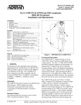
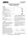
Section 61104020L4-5C
Issue 3, May 2002
CLEI Code: D4C5BENB_ _
D4 U-BR1TE V w/PWR and DDS Loopbacks
ISDN 2B1Q Interface
Installation and Maintenance
CONTENTS
1. GENERAL .................................................................. 1
2. INSTALLATION ....................................................... 2
3. TESTING .................................................................... 7
4. MAINTENANCE ..................................................... 13
5. WARRANTY AND CUSTOMER SERVICE ......... 14
TABLES
Table 1. SW1, SW3, and SW6 Option Settings ............... 5
Table 2. Rotary Switch Options ....................................... 7
Table 3. LED Indication ................................................... 7
1. GENERAL
This practice provides installation and maintenance
procedures for the ADTRAN D4 U-BR1TE V w/PWR
and DDS Loopbacks, P/N 1104020L4. Figure 1 is an
illustration of the U-BR1TE V.
ISDN/DDS
The U-BR1TE employs features for both ISDN and
DDS transport. ISDN comprises the major
functionality and is described in this section. A
description of DDS functionality is located in
Section 3.
Revision History
Issue 3 of this document includes 2B leased mode
operation and revises the CLEI code.
61104020L4-5C
1104020L4
LPBK
AD6
CRTX
LPTX
NT1
AD5
AD1
AD4
LP
SW1
AD3
AD2
B1
B2
TEST
CR
2
ACT
TEST
ERR
1
FIGURES
Figure 1. ADTRAN U-BR1TE V ..................................... 1
Figure 2. Backplane Pin Assignments .............................. 3
Figure 3. Time Slot Assignments for 2B+D Service in
SLC Mode I w/ D1D Counting ......................... 3
Figure 4. Time Slots that CANNOT Contain BR1TE
Cards .................................................................. 4
Figure 5. SW1, SW3, and SW6 Labeling ......................... 4
Figure 6. Position Switch Settings at Network Locations
for ISDN Applications ...................................... 6
Figure 7. U-BR1TE V IDSL/DDS Circuit Diagram ...... 10
Figure 8. IDSL/DDS Loopback Response ..................... 11
Figure 9. ADTRAN U-BR1TE Bidirectional Loopback .. 12
Figure 10. IDSL/DDS Remote End Initiated Loopback,
Local Loop ...................................................... 12
Figure 11. IDSL/DDS Remote End Initiated Loopback,
Customer Loop ................................................ 12
Figure 12. IDSL/DDS Trouble Codes .............................. 13
Figure 13. DS0 Latching Loopback ................................. 14
U-BR1TE V
D4-UBR1PWR/DDS
NORM
OUT
(Rx)
SW3
IN
(Tx)
SW2
PTRN
L
O
G
I
C
SW4
SW5
SW6
Figure 1. ADTRAN U-BR1TE V
Functional Description
The U-BR1TE V is a line card that plugs into a single
channel slot of an AT&T D4/SLC®-96 channel bank.
It provides an ISDN U-interface and allows the
transport of Basic Rate 2B+D information over T1
carriers and twisted pair wiring. The U-BR1TE V
combines the functionality of a standard U-BR1TE V
and a U-Repeater Powering Module which will
simplify the installation of the U-Repeater. Span
powering also allows deployment of 2-wire DDS
when an IDSL OCU-R is used to terminate the ISDN
local loop. This eliminates the need to provide AC
power at the customer premises.
The U-BR1TE V is used at both the Central Office
Terminal and Remote Terminal locations. Clear
channel capability (B8ZS) is not required of the T1
facility if zero byte substitution is enabled. The
U-BR1TE V plugs into a single channel slot of the D4
bank, but can require three time slots when
transporting 2B+D information. Block error rate
performance over the T1 facility is monitored and is
available to the network.
Trademarks: Any brand
names and
product names included
in this
Section
61104020L4-5,
Issue
3 document are
trademarks, registered trademarks, or trade names of their respective holders.
1
Features
The U-BR1TE V features support both ISDN and
DDS, plus features common to both as listed here:
ISDN Features
• Span powers U-repeaters with 43 mA @ -28 to
-120 VDC for ISDN applications.
• Internal test pattern allows for testing of
individual B Channels without requiring external
test equipment.
• Transportation of ISDN Basic Rate 2B+D
information over T1 facilities in the 3-DS0
format specified in TR-NWT-000397.
• B1 and B2 loopback addressability at the front
panel for the NT1 and up to six devices in the
Network-to-Customer direction.
DDS Features
• Span powers an IDSL OCU-R with 12 mA @
-120 VDC for DDS applications.
• Transmit MUX-Out-of-Sync (MOS) trouble code
upstream for IDSL loss of signal, loss of sync, or
open loop.
• Perform bidirectional loopback (loop and
network) when commanded into DS0 DP
loopback from the network direction only.
• Initiate in-band OCU loopback to loop the IDSL
OCU-R via front panel push button.
• Loopback release in response to TIPs per
TR62310 or front panel push button.
• Remap all subsequent DS0 DP loopback codes into
respective EOC loopbacks to loop back respective
downstream U-Repeaters, TRISDN elements, and
U-BR1TES when optioned for 1B+D, or 2B+D.
• Pass OCU loopback code through to loop the
IDSL OCU-R.
• Pass CSU loopback code through to loop the
CSU/DSU and simultaneously send a remap to
the NT1 EOC address.
• Returns Abnormal Station Code (ASC) to the
network in B1 during loopback conditions
initiated by the IDSL OCU-R.
2B Leased Mode Features
• DDS loopback operation during 2B data mode
only.
Common Features
• ISDN 2B1Q interface which meets all Layer 1
requirements as specified in ANSI T1.601-1991.
• 18 kft nominal range on mixed gauge wire.
2
• All Layer 1 maintenance function and performance
monitoring as specified in TR-NWT-000397 and
TR-TSY-000829.
• Distinctive metallic DC test signature to identify
either line unit LT or line unit NT mode of
operation as specified in TR-NWT-0000397.
• Provides loopback capability for full 2B+D as well
as individual B channels in both loop and carrier
directions. Individual B channel loopbacks may be
initiated at the U-BR1TE V front panel or from a
remote location through the maintenance channel.
• DS0 logic level transmit and receive data access
through front panel bantam jacks.
• A built-in Cyclic Redundancy Check (crc) clock
error detector allows for local performance
monitoring at the front panel without test equipment.
• Addressing and error status with front panel LED
indicators. Test function chosen by a front panel
ten-position rotary switch.
The U-BR1TE V is compatible in functionality and is
interchangeable with the U-BR1TE III w/PWR
(1103020L4) except when used in DDS applications.
In addition to being compatible and interchangeable
with the just mentioned ADTRAN unit, the U-BR1TE
V, adds features in leased mode, including DS0 DP
latching loopback and sending Multiplexer-Out-of
-Sync (MOS) toward the network.
2. INSTALLATION
C A U T I O N !
SUBJECT TO ELECTROSTATIC DAMAGE
OR DECREASE IN RELIABILITY.
HANDLING PRECAUTIONS REQUIRED.
After unpacking the unit, inspect it for damage. If
damage is noted, file a claim with the carrier, then
contact ADTRAN. See Warranty and Customer
Service.
Physical Requirements
The U-BR1TE V plugs into a single D4/SLC-96
channel slot. The backplane pin assignments are
illustrated in Figure 2. When provisioned for basic
rate service (2B+D), the U-BR1TE V occupies three
time slots. In a D4 or SLC-96 Mode III channel bank,
it occupies the time slot associated with the physical
channel slot that it occupies plus the next two time
slots to the right. The physical channel slots, whose
time slots are used in this manner, must remain
unoccupied.
Section 61104020L4-5, Issue 3
61104020L4-5C
+5V
INCLK
TDATA
RCLK
RWD
RSQ
-48V
R*
GND
28
1
29
2
30
3
31
4
32
5
33
6
34
7
35
8
36
9
37
10
38
11
39
12
40
13
41
14
42
15
43
16
44
17
45
18
46
19
47
20
48
21
49
22
50
23
51
24
52
25
53
26
54
27
In SLC-96 Mode I with D1D counting channel bank,
the time slots are allocated as shown in Figure 3 with
two time slots per physical channel slot.
FRM GND
-12V
GND
+12V
GND
TWD
TSP
TSQ
RNPCN
The unit uses two time slots in one physical slot and a
time slot from an adjacent slot when configured for
2B+D operation. When selected for Slot 1, 4, 7, or 10
operation, the unit occupies the two time slots
associated with the physical slot in which it resides
and the upper time slot of the next adjacent physical
slot.
TDCLK
NGATE
RSP
RNDIS
-48R
When selected for Slot 2, 5, 8, or 11 operation, the unit
occupies the lower time slot of the occupied physical
slot and the adjacent two time slots of the next
physical slot to the right. When using the Slot 2, 5, 8,
11 option, the physical slot to the right must be left
vacant. A unit selected for one or two time slots,
B1+D, B2+D, B1, B2, 2B, and D only, occupies only
the two time slots associated with the physical slot
used. In this configuration, option the unit for Slot 1,
4, 7, or 10.
NSEIZE
T*
MCLK
*2B1Q Signal
Terminals
Figure 2. Backplane Pin Assignments
UTS
UTS
UTS
C1
C2
*
LTS
LTS
LTS
UTS =
upper time slot
PS4
PS5
PS6
PS7
PS8
PS9
PS10
PS11
PS12
C1
C2
C1
C2
C1
C2
Unoccupied
PS3
Unoccupied
PS2
Unoccupied
PS1
LTS = lower time slot
C1 =
physical location of U-BR1TE
optioned as "slots 1, 4, 7, 10"
C2 =
physical location of U-BR1TE
optioned as "slots 2, 5, 8, 11"
PS = physical slot
(1 physical slot consists of 2 time slots)
* = Must be empty - time slots are being used
by U-BR1TE card in C2
NOTE: Unoccupied slots should have blank panels installed to prevent inadvertant use.
Figure 3. Time Slot Assignments for 2B+D Service in SLC Mode I w/ D1D Counting
61104020L4-5C
Section 61104020L4-5, Issue 3
3
See Figure 4 for additional channel slot deployment
restrictions for each bank type.
3
4
5
6
7
8
9
10
11
12
3
4
5
6
7
8
9
10
11
12
13
14
15
16
17
18
19
20
21
22
23
24
13
14
15
16
17
18
19
20
21
22
Time Slots
5
6
7
17
21
2
3
7
11
15
19
D4 Bank:
D1D Channel
Counting, or
SLC-96
Carrier Mode
3 Terminal:
D4 Channel
Counting
9
10
11
12
6
8
10
14
18
22
8
12
16
20
24
11
12
**
3
2
7
3
4
11
15
1
5
9
13
13
14
15
16
5
23
6
*
** **
*21
17
**
**
17
18
19
23
**
4
7
9
10
8
12
16
2
6
10
14
19
20
21
4
8
Physical Slots
Time Slots
Physical Slots
22
*
** **
*
18 22
**
**
23
24
Physical Slots
11
Physical Slots
1
2
3
4
5
6
7
8
9
10
1
3
5
7
9
11
13
15
17
19
2
4
6
8
10
12
14
16
18
20
13
14
15
16
17
18
19
20
21
22
20
24
12
*
** **
*
22 24
**
**
23
24
21
Time Slots
Option Switch Settings
Figure 5 displays the locations for SW1, SW3, and
SW6 on the U-BR1TE V. Table 1 contains the option
settings for SW1, SW3, and SW6 of the U-BR1TE V.
23
Time Slots
Physical Slots
* A channel unit with B+D service cannot occupy this slot
** A channel unit with 2B+D service cannot occupy this slot
LULT(RT)
O
1
SW3 N
2
O 1 2 3 4 5 6
N
SW2
Figure 4. Time Slots that CANNOT Contain
BR1TE Cards
LUNT(COT) TANDEM
LULT(RT)
SW3
D4 Bank Requirements
The COT D4 bank must be configured with an OIU-2
selected for external timing. The COT bank must be
provided with an external composite clock
synchronized with the network.
ADJ
B1
B2
D
ZBS DIS
4
13
Interface Requirements
The U-BR1TE V unit includes two interfaces. The
loop-side interface is an ISDN U-interface which is
used to deliver Basic Rate service. The carrier-side
interface is a D4/SLC-96 channel bank interface
which is used to insert data into the 1.544 Mbps T1
stream. Only the polarity-insensitive T and R leads
are used in the cross-connection.
TRM
3
9
Physical Slots
ZBS EN
2
5
**
**
23
24
SW6
O
N
1
ADJ
2
LUNT(COT) TANDEM
NORM
POWER
O1 2 3 4 5 6
N
SW4
NORM
POWER
SW1
ZBS EN
1
1
1
SLC-96
Carrier
Mode 3
Terminal:
D1D Channel
Counting
Physical Slots
B1
B2
D
ZBS DIS
SLC-96
Carrier
Mode 1
Terminal:
D1D Channel
Counting
2
2
TRM
D4 Bank:
D4 Channel
Counting
1
1
SLC-96 Bank Requirements
The COT SLC-96 bank must be configured with a
special service unit (SSU) selected for external timing.
The COT SLC-96 bank must be provided with an
external composite clock synchronized with the
network.
Figure 5. SW1, SW3, and SW6 Labeling
4
Section 61104020L4-5, Issue 3
61104020L4-5C
Table 1. SW1, SW3, and SW6 Option Settings
Switch
SW1-1
SW1-2
SW1-3
SW1-4
SW1-5
Label
TRM
TRM
B1
B2
D
SW1-6
On
Off
Description
Bank Type Selection
Selects the bank type for the U-BR1TE V.
Service Level Selection
ZBS DIS
ZBS EN
SW3-2
Count/Slot
SW1-1
SW1-2
D4
D4 Counting
D1D Counting
On
On
Off
On
SLC I
CU in slots 1, 4, 7, 10
CU in slots 2, 5, 8, 11
On
Off
On
Off
SLC III
D4 Counting
D1D Counting
On
Off
On
On
ISDN
2B+D
On
On
On
Leased (128 kbps)
2B
On
On
Off
ISDN/DDS
B1+D
On
Off
On
ISDN
B2+D
Off
On
On
DDS/Leased
B1
On
Off
Off
Leased
B2
Off
On
Off
ISDN
D
Off
Off
On
In 2B+D, B1+D, or B2+D the ZBS option must be set the same for the COT and
RT. SW1-6 should be set toward "ZBS EN" for AMI-provisioned carriers. The
switch setting is optional for B8ZS-provisioned carriers. In non-D channel modes,
ZBS must be disabled when DDS service rate is 64 kbps, or 56 kbps with secondary
channel. Consult local provisioning guidelines.
Disables ZBS
Enables ZBS
Termination Mode
LULT (RT)
LUNT (COT)
Bank
Selects the service level. The U-BR1TE V may be optioned to deliver full ISDN
(2B+D) or any of the following levels of service.
Service
SW1-3
SW1-4
SW1-5
Type
Option
(B1)
(B2)
(D)
Zero Byte Substitution
SW3-1
On
Off
Function
This switch should be set toward "LULT" when the unit is installed as Adjacent-to
U-Repeater, Adjacent-to-Customer, or Tandem Office Source configuration. This
switch should be set toward "LUNT" for Adjacent-to-Switch and Tandem Office
Sink configurations.
LULT Mode (RT typical)
LUNT Mode (COT typical)
(See Figure 6)
Function dependent upon SW3-1
setting.
LULT Mode (SW3-1 On)
DC sealing current provided
DC sealing current not provided
On
Off
ADJ
TANDEM
On
Off
ADJ
TANDEM
LUNT Mode (SW3-1 Off)
In the LUNT(COT) mode, SW3-2 controls periodic wake-up tone. Periodic wakePeriodic wake-up tone not provided up tones should be disabled when located in an Adjacent-to-Switch location (SW3-2
Periodic wake-up tone provided
On). Periodic wake-up tones are required (SW3-2 Off ) when located in a Tandem
Office Sink configuration, or when adjacent to a device requiring wake-up tones,
such as a Newbridge switch.
SW6
On
POWER
Powering provided toward the
customer U-interface.
Automatically determines which of the following modes of operation is appropriate;
• Supply a constant 43 mA to power an ADTRAN ISDN U-Repeater II, URepeater III.
• Supply a constant -120 Vdc to power an ADTRAN IDSL OCU-R.
Off
NORM
Normal
No powering provided toward the customer U-interface.
In the LULT(RT) mode, SW3-2 controls sealing current. When used in an
Adjacent-to-Customer configuration, sealing current should be provided (SW3-2
On). In a Tandem Office Source configuration, sealing current is not required, and
should be disabled (SW3-2 Off ).
Note: Power option should only be used in the LULT (RT) configuration.
61104020L4-5C
Section 61104020L4-5, Issue 3
5
Figure 6 displays the position switch settings at
network locations.
Front Panel Features
The U-BR1TE V front panel features a two position
DIP switch, a recessed pushbutton, a rotary switch, a
bantam jack, and LEDs, as illustrated in Figure 1.
The B1/B2 DIP Switch selects the desired bearer
channel, B1 or B2, to be tested during local tests
using the U-BR1TE V front panel.
D4/SLC-96
COT
2-Wire
L
U
N
T
D4/SLC-96
RT
Channel
Bank
Channel
Bank
Adjacent to
Switch
Adjacent to
Customer
SW3
1 - LUNT (COT)
2 - ADJ
ISDN
Switch
D4/SLC-96
RT
L
U
L
T
T1
Channel
Bank
Channel
Bank
Adjacent to
Switch
Adjacent to
Customer
SW3
1 - LUNT (COT)
2 - ADJ
2-Wire
ISDN
RP
2-Wire
Loop
Customer
NT1
2-Wire
Customer
NT1
Note:
Refer to Table 1 for switch
function descriptions.
SW3
1 - LULT (RT)
2 - ADJ
SW6
Norm
SW6
Norm
D4
D4
L
U
N
T
2-Wire
SW6
Power
D4/SLC- 96
COT
L
U
N
T
LED indicators display current status of the unit, as
listed in Table 3.
SW3
1 - LULT (RT)
2 - ADJ
SW6
Norm
2-Wire
L
U
L
T
T1
The NORM/PTRN DIP Switch is recessed to prevent
inadvertent operation. The ten-position rotary switch
is used to determine the specific test that will be
performed, including downstream loopbacks
(see Table 2).
L
U
L
T
T1
2-Wire
L
U
N
T
D4/SLC-96
RT
D4/SLC-96
COT
L
U
L
T
T1
Channel
Bank
Channel
Bank
Adjacent to
Switch
Tandem Office
(Source)
Tandem Office (Sink)
SW3
1 - LUNT (COT)
2 - ADJ
SW3
1 - LULT (RT)
2 - TANDEM
SW3
1 - LUNT (COT)
2 - TANDEM
SW3
1 - LULT (RT)
2 - ADJ
SW6
Norm
SW6
Norm
SW6
Norm
SW6
Norm
Channel
Bank
2-Wire
Customer
NT1
Channel
Bank
Adjacent to Customer
Figure 6. Position Switch Settings at Network Locations for ISDN Applications
6
Section 61104020L4-5, Issue 3
61104020L4-5C
Table 2. Rotary Switch Options
Display
Interpertation
AD1
Address #1, address of this unit
AD2
Address #2, the next downstream unit away
AD3
Address #3, the second unit downstream
AD4
Address #4, the third unit downstream
AD5
Address #5, the fourth unit downstream
AD6
Address #6, the fifth unit downstream
LPBK
Loopback, forces this unit to loopback the
selected B1 or B2 channel. Loopbacks occur in
both the customer and network directions.
CRTX
Carrier transmit, in the carrier direction
LPTX
Loop transmit, in the loop direction
NT1
NT1, address of the NT1
Latching OCU in DDS mode
3. TESTING
The U-BR1TE V responds to embedded operation
channel loopbacks, including B1, B2, and 2B+D, when
configured for D channel operation. When used in B1
configuration (non-D channel modes of operation) the
U-BR1TE V will respond to an in-band DS0 DP
latching loopback sequence. When remote testing is
not available, or during isolation of trouble or
equipment malfunction, the U-BR1TE V front panel
provides local test capabilities. Using the internal
2047 pseudorandom test pattern generator or the
bantam jacks allows craft personnel to test in both the
downstream and upstream directions, including
loopback for 6 addressable ISDN devices and the
customer’s NT1.
Table 3. LED Indication
Indicator
Loop Status (LP)
Color
Description
Off
Indicates loop synchronization has been established and no Near End
Block Errors (NEBE) are being received from the Loop interface.
Red
Illuminated when U-interface is out of sync or has a loss of signal.
Yellow
Flashes yellow upon receipt of a NEBE. During Local Performance
Monitoring (see Testing) will flash yellow when BER >10-6 is
detected and illuminate yellow when a BER > 10-5 is detected.
Off
Indicates carrier synchronization (framing per TR-TSY-000397) has
been established and no Near End Block Errors (NEBE) are being
received from the Carrier interface.
Red
Illuminated when no framing pattern is received.
Yellow
Flashes yellow upon receipt of a NEBE. During Local Performance
Monitoring (see TESTING) will flash when a BER > 10-6 is detected and
illuminate yellow when a BER > 10-5 is detected.
Activation (ACT)
Green
ISDN Application - Indicates that the terminal equipment has
exchanged ACT bits with the ISDN switch.
DDS Application - Indicates loop is terminated with an OCU-R.
ISDN Application - Once per second indicates that the ACT bit is being
sent in one direction only.
Test (TST)
Yellow
Solid yellow when a front panel test has been successfully initiated or
when responding to a 2B+D loopback request.
Flashes yellow once every two seconds when responding to a B1
loopback request or when forced into a B1 loopback from the front
panel.
Flashes yellow twice every two seconds when responding to a B2
loopback request or when forced into a B2 loopback from the front
panel.
Green
Solid Green when in Local Preformance Monitoring or when the local
test pattern gen/det is invoked.
Red
Flashes red when errors are seen by local test pattern detector.
Carrier Status (CR)
Error (ERR)
61104020L4-5C
Section 61104020L4-5, Issue 3
7
The front panel bantam jacks accommodate standard
DS0 Logic Testers such as the TPI 108/109 RT II or
FIREBERD 4000/6000 which perform both the
upstream and downstream testing.
NOTE
On DDS circuits the internal 2047 Pattern
Generator on the U-BR1TE V should be used
only when the service is operating at 64 kbps. If
DDS service is operating at 56 kbps or less, the
U-BR1TE V will display errors if the internal
2047 Pattern Generator is used. The use of
external DDS test equipment is required for all
data rates at 56 kbps and below.
Loopback Tests (ADR1 - ADR6, NT1)
Loopbacks in the Network-to-Customer direction can
be initiated from either the ISDN switch or the front
panel. Either the internal 2047 test pattern or a DS0
digital test set provide the 64 kbps test pattern to be
tested in B1 or B2. When initiating loopbacks from
the U-BR1TE V front panel, the downstream direction
is automatically selected based on the card position in
the network.
To initiate a loopback using the internal 2047 test
pattern, perform the following:
1. Select the desired loopback address using the tenposition rotary switch. See Table 2.
2. Select the desired bearer channel using the B1/B2
DIP switch.
3. Select PTRN on the NORM/PTRN DIP switch.
4. Depress the recessed TEST pushbutton to initiate
the test. The TEST LED will illuminate GREEN
when the loopback is established to the selected
address, and the ERR LED should go out
following synchronization to the test pattern. If
the selected address does not respond, the TEST
LED will remain out and the ERR LED will
illuminate.
5. To insert one bit error, momentarily (for less
than two seconds) depress the TEST pushbutton.
The ERR LED should flash upon receipt of the
injected error.
6. Tests to additional network addresses may be
performed by changing the selector knob to the
desired address. It is not necessary to exit the test
mode to select a new address.
8
7. To deactivate the loopback, depress the TEST
pushbutton for two seconds, until the GREEN
TEST LED is extinguished, or select NORM on
the NORM/PTRN DIP switch.
To initiate a loopback at any data rate when using an
external DS0 digital test set, perform the following:
1. Insert the TX and RX bantam plug of the DS0
digital test set into the U-BR1TE V respective
front panel bantam jacks. Connect the clock
input of the DS0 digital test set to the channel
bank’s clock source (the D4 OIU, or the SLC-96
SSU). Configure the test set for Near Logic and
64 kbps.
2. Select the desired loopback address using the tenposition rotary switch. See Table 2.
3. Select the desired bearer channel using the B1/B2
DIP switch.
4. Depress the recessed TEST pushbutton to initiate
the test. The TEST LED will illuminate
YELLOW when the loopback is established to
the selected address. If the selected address does
not respond, the TEST LED will remain off.
Observe the DS0 digital test set for bit errors.
5. Tests to additional network addresses may be
performed by changing the selector knob to the
desired address. It is not necessary to exit the test
mode to select a new address.
6. To deactivate the loopback, depress the TEST
pushbutton or remove the transmit bantam plug.
Upon deactivation of the test, the TEST LED will
go out.
Point-to-Point Test (CRTX, LPTX)
A point-to-point (straight-away) test can be performed
to either the U-interface (LPTX) or the T-1 carrier
interface (CRTX). In both cases, either the internal
2047 test pattern generator or a DS0 DP digital test set
is used to verify the performance of the selected
bearer channel.
To initiate a point-to-point test using the internal 2047
test pattern, perform the following:
1. Select the desired test direction, LPTX or CRTX,
using the ten-position rotary switch. See Table 2.
2. Select the desired bearer channel using the B1/B2
DIP switch.
3. Select PTRN on the NORM/PTRN DIP switch.
Section 61104020L4-5, Issue 3
61104020L4-5C
4. Depress the recessed TEST pushbutton to initiate
the test. The TEST LED will illuminate GREEN
and the ERR LED should go out following
synchronization to the test pattern from the far
end.
5. If the far end unit is a U-BR1TE V using the
internal 2047 test pattern, perform steps 1
through 4, choosing the same front panel switch
setting. If the far end is a test set, ensure it is
configured for a 2047 test pattern.
6. To insert one bit error, momentarily (for less than
two seconds) depress the TEST pushbutton. Bit
errors will be seen at the far end test unit.
7. To deactivate the loopback, depress the TEST
pushbutton for two seconds, until the GREEN
TEST LED is extinguished, or select NORM on
the NORM/PTRN DIP switch. Upon deactivation
of the test, the TEST LED will go out.
To initiate a point-to-point test using an external DS0
digital test set, perform the following:
1. Insert the TX and RX bantam plug of the DS0
digital test set into the U-BR1TE V respective
front panel bantam jacks. Connect the clock
input of the DS0 digital test set to the channel
banks clock source (D4’s OIU, or the SLC-96
SSU). Configure the test set for Near Logic and
64 kbps.
2. Select the desired test direction, LPTX or CRTX,
using the ten-position rotary switch. Refer to
Table 2.
3. Select the desired bearer channel using the B1/B2
DIP switch.
4. Depress the recessed TEST pushbutton to initiate
the test. The TEST LED will illuminate
YELLOW.
5. If the far end unit is a U-BR1TE V using a DS0
digital test set, perform steps 1 through 4,
choosing the same front panel switch setting.
Ensure that both test sets are configured for the
same test pattern (511, 2047). If the far end unit
is a U-BR1TE V using the internal 2047 test
pattern, perform steps 1 through 4 of the previous
section.
6. Observe the DS0 digital test set for bit errors.
7. To deactivate the loopback, depress the TEST
pushbutton, or remove the transmit bantam plug.
Upon deactivation of the test, the TEST LED will
go out.
61104020L4-5C
Local Loopback (LPBK)
A bilateral loopback can be initiated from the
U-BR1TE V front panel for either bearer channel. A
local test pattern source is not required for this test.
To initiate a local loopback, perform the following:
1. Select the desired bearer channel using the B1/B2
DIP switch.
2. Select LPBK using the ten-position rotary switch.
See Table 2.
3. Depress the recessed TEST pushbutton to initiate
the test. The TEST LED will illuminate
YELLOW.
4. To deactivate the loopback, depress the TEST
pushbutton. Upon deactivation of the test, the
TEST LED will go out.
Local Performance Monitoring
Performance Monitoring of the local T1 carrier system
and 2-wire U-interface of the ISDN data can be
performed from the front panel without interruption of
service to the customer. For this test, bearer channel
selection is not applicable and a test pattern source is
not required. To initiate a local performance
monitoring session, perform the following:
1. Ensure the NORM/PTRN DIP switch is in the
NORM position, and that a bantam plug is NOT
installed in the front panel TX bantam jack.
2. Select ADR1 using the ten-position rotary switch.
3. Depress the recessed TEST pushbutton to initiate
the test. The TEST LED will illuminate GREEN.
4. The total number of Near End Block Errors
(NEBE) received are simultaneously displayed as
crc errors with the LP and CR CRC status LEDs.
(See Table 3).
5. To exit local performance monitoring, depress
the TEST button for two seconds or longer.
Upon deactivation of the test, the TEST LED will
go out.
Section 61104020L4-5, Issue 3
9
IDSL/DDS Description
The U-BR1TE V may be deployed in the adjacent to
customer position to provide transport for DDS/Frame
Relay services with an ADTRAN IDSL OCU-R. This
allows pair savings over traditional DDS deployment
on local loops up to 18 kft of mixed gauge wire. The
IDSL OCU-R is used to terminate the U-interface at
the customer’s premises provided by the U-BR1TE V
and to convert the 2-wire ISDN signal to a 4-wire
AMI DDS signal for presentation to the customer.
Together, the U-BR1TE V and IDSL OCU-R allow
testing over the ISDN transport network to be
performed with traditional DDS methods. In this
mode U-BR1TE Vs may be placed in tandem and
function as DS0 DPs while the IDSL OCU-R
functions as an OCU. See Figure 7 for various
U-BR1TE V DDS arrangements.
DDS Testing
For leased mode or DDS applications with the
U-BR1TE V the D channel is typically disabled.
Without the D channel, standard ISDN EOC
loopbacks are unavailable to the ISDN transport
system and testing may only be accomplished by
using the in-band DDS loopback commands. The
U-BR1TE V responds to latching loopback sequences
for the DS0 DP. The U-BR1TE V allows the OCU
loopback command to pass in-band downstream to the
IDSL OCU-R.
Upon receipt of a DS0 DP latching loopback sequence
the U-BR1TE V initiates a bilateral loopback for the
B1 channel. This bilateral loopback allows testing of
the 2B1Q local loop to the IDSL OCU-R
simultaneously with network testing to the U-BR1TE
V.
SLC 96
A
1
4W DS0 DP
or
OCU
B
T1
4W
Digital
C
4W DS0 DP
or
DCS
4W DS0 DP
or
DCS
T1
2-Wire
Local
Loop
U-BR1TE
1B
E
IDSL OCU-R
Customer
Premises
RT
D4/DCS
D4
D
COT/DCS
SW3
1 - LULT (RT)
2 - ADJ
SW6
Power
Non-ADTRAN U-BR1TE 1B+D
A
2
4W DS0 DP
or
OCU
B
T1
2W
Digital
D
C
U-BR1TE
1B
U-BR1TE
1B+D
D4
COT
T1
2-Wire
Local
Loop
U-BR1TE
1B+D
E
IDSL OCU-R
Customer
Premises
RT
SW3
1 - LULT (RT)
2 - TANDEM
D4
SW6
Normal
3
4W
Digital
A
B
4W DS0 DP
or
OCU
4W DS0 DP
or
DCS
4W DS0 DP
or
DCS
D4
D4
T1
C
D
T1
U-BR1TE
1B
2-Wire
Local
Loop
E
IDSL OCU-R
Customer
Premises
D4
D4
Equipment Requirements
1 D & 3 D: Must be 1104020L4 w/ power enabled
SW3
1 - LULT (RT)
2 - ADJ
SW6
Power
2 B: Must be 1104020L4 w/ Power Disabled
2 E: Requires local AC power
NOTE: Refer to Table 1 for DIP switch function
descriptions.
Figure 7. U-BR1TE V IDSL/DDS Circuit Diagram
10
Section 61104020L4-5, Issue 3
61104020L4-5C
DS0 DP Loopback EOC Remapping
Upon receipt of subsequent DS0 DP loopback codes
when the D channel is disabled, the U-BR1TE V
remaps the subsequent DS0 DP loopback sequences
into the respective ISDN EOC loopback messages.
This capability will permit all downstream ISDN D
channel enabled U-BR1TEs, U-Repeaters, and
TRISDN elements to respond to standard DDS DS0
DP loopback commands via the ISDN EOC as shown
in Figure 8.
Test
Head
D4/SLC-96
T1
U-BR1TE
1B+D
U-BR1TE
1B
DS0 DP #1
DS0 DP #2
Loopback
ISDN
RPTR
IDSL
OCU-R
DS0 DP #3
OCU
Response
Figure 8. IDSL/DDS Loopback Response
NOTE
For DDS circuits with the D channel disabled,
all tandem U-BR1TE elements should be
ADTRAN U-BR1TE Vs with DDS Loopback
Capability for remote end test operation to
function properly. See 2B in Figure 7. In D
channel disabled applications, older non-DDS
vintage U-BRITEs may not pass the OCU
latching loopback sequence to the IDSL OCU-R.
Upon receipt of an OCU latching loopback sequence
the U-BR1TE V passes the OCU sequence in-band
downstream to the IDSL OCU-R. U-BR1TE Vs do
not respond to the CSU latching loopback command
but simultaneously pass it through to the CSU/DSU
while mapping the NT1 EOC address. The IDSL
OCU-R reverses sealing current on its 4-wire AMI
DDS interface to place the customer CSU into
loopback upon receipt of the CSU latching loopback.
61104020L4-5C
The following data sequence enables the DS0 DP,
OCU, and CSU latching loopbacks:
1.
Minimum of 35 transition in progress (TIP)
bytes (X0111010).
2. Minimum of 35 loopback select code (LSC)
bytes: DS0 DP (X0000101),OCU
(X1010101), CSU (X0110001).
3. Minimum of 100 loopback enable (LBE) bytes
(X1010110).
4. Minimum of 32 far-end voice (FEV) bytes
(X1011010).
X Denotes Don’t Care bit - either a 1 or a 0.
If the U-interface of the U-BR1TE V is not in sync,
the unit transmits MUX-Out-of-Sync (X0011010).
Disabling DS0 DP, OCU, or CSU latching loopback
sequence:
1. Minimum of 35 TIP bytes.
or by pressing the front panel loopback button.
Front Panel Tests
The valid front panel tests in leased modes are ADR1,
CRTX, LPTX, and LPBK for all circuit positions.
NT1, ADR1-ADR6 loopback tests are valid for the
LULT mode only. ADR2 would be used to test a URepeater or ADR2 and ADR3 would be used to test
TRISDN elements respectively.
All active in-band loopbacks may be disabled by
pressing the front panel loopback button once when a
test set is not connected to the bantam jacks.
Initiate Loopback at IDSL OCU-R
When used for DDS, the D4 U-BR1TE may initiate a
loopback at the IDSL OCU-R. The in-band latching
OCU loopback code is sent to loop the IDSL OCU-R
when the NT1 address is selected on SW2. To invoke
the OCU loopback at the IDSL OCU-R, press the Test
button with the front panel test knob in the NT1
address location.
Section 61104020L4-5, Issue 3
11
Performance Monitoring
Local Performance Monitoring is available only for
the U-interface, when configured for a leased mode of
operation. See the subsections entitled Loopback
Tests, Point-to-Point Test, and Local Loopback for
applicable test descriptions.
ADTRAN U-BR1TE Bidirectional Loopback
In LULT Mode, the ADTRAN U-BR1TE will execute
a bidirectional loopback when performing DS0 DP
loopback. See Figure 9 for an illustration of the
bidirectional loopback.
Remote End Initiated LBK Tests
The U-BR1TE supports loopbacks generated from the
remote unit which allows testing to be performed
ADTRAN U-BR1TE
IDSL OCU-R
Test Set
without coordination with the CO or test center.
Loopbacks initiated by the OCU-R front panel LBK
pushbutton aid in system turn up testing or
troubleshooting from the remote end.
The U-BR1TE responds to a loopback command
initiated at the OCU-R as follows:
Pressing the OCU-R LBK pushbutton on the OCU-R
once will initiate a loopback at the U-BR1TE toward
the customer. See Figure 10. This allows data to be
sent from the remote end to test the local loop and the
OCU-R. This loopback is indicated by a flashing
CUST LBK LED on the IDSL OCU-R and a solid
LBK LED on the U-BR1TE.
Pressing the OCU-R LBK pushbutton a second time
will initiate a loopback at the OCU-R toward the
4-wire DDS (CPE) interface. A solid CUST LBK
LED on the IDSL OCU-R indicates a loopback at the
IDSL OCU-R toward the customer equipment.
See Figure 11. Pressing the OCU-R LBK pushbutton
a third time disables all current latching loopbacks
initiated by the OCU-R LBK pushbutton.
Bidirectional
loopback
Figure 9. ADTRAN U-BR1TE Bidirectional
Loopback
If errors exist the loopbacks can help determine the
source; either the local loop or the OCU-R.
4-Wire
CPE Interface
OCU-R
ASC 9Eh
U-BR1TE
Local Loop
Test
Set
Loopback
Pushbutton
Push once for
U-BR1TE Loopback
Figure 10. IDSL/DDS Remote End Initiated Loopback, Local Loop
4-Wire
CPE Interface
ASC 9Eh
OCU-R
ASC 9Eh
U-BR1TE
Local Loop
Loopback
Pushbutton
Test
Set
Push twice for
OCU-R Loopback
Figure 11. IDSL/DDS Remote End Initiated Loopback, Customer Loop
12
Section 61104020L4-5, Issue 3
61104020L4-5C
During a remote end initiated loopback the system
transmits ASC 9Eh toward the network, indicating an
out-of-service condition generated by the remote end,
as shown in Figures 10 and 11.
All IDSL/DDS system latching loopbacks, whether
initiated by the IDSL DCU-R craft interface, LBK
pushbutton, CO, or from a remote Test Center, can be
released by sending 35 DDS loop down TIP bytes
<X0111010> (Where X is a “don’t care” bit). All
existing latching loopbacks will also be disabled by
pressing the LBK pushbutton on the CO or remote
unit.
NOTE
The remote end test feature is only supported
when the upstream U-BR1TE is an ADTRAN
D4 or Series 5 U-BR1TE with DDS Loopback
capability. Other U-BR1TEs will ignore the
loopback command sent by pressing the IDSL
OCU-R LBK button.
IDSL/DDS Trouble Code
The IDSL/DDS system provides a quick diagnosis in
the case of a circuit condition where continuity is
broken. The trouble code type received by a tester
determines whether the open condition is occurring on
the local loop or at the customer premises. In the
event of a 2-wire DSL loss of signal, loss of sync, or
open condition caused by an open conductor or
disconnected 2-wire loop, the U-BR1TE V transmits a
MUX-Out-of-Sync trouble code (MOS 9Ah) into the
network as shown in Figure 12. During a similar
out-of-service condition at the customer premises, the
IDSL OCU-R transmits Abnormal Station Code
(ASC 9Eh) upstream toward the network as shown in
Figure 12.
Customer Premises
Channel Bank
Open 2-wire Loop
MOS 9Ah
U-BR1TE
IV
IDSL OCU-R
DSU
2B Leased Mode Operation
The U-BR1TE V is deployed in 2B leased line
operation to provide DDS/Frame Relay services to
ISDN equipment. By using the 2-wire ISDN interface
for 128 kbps data rate, the U-BR1TE V Leased Mode
Operation allows pair savings over traditional DDS
deployment. DDS/Frame Relay support allows
loopback testing to be performed across the ISDN
transport system in this configuration.
The U-BR1TE V will decode DDS latching loopback
sequences coming from the carrier into eoc loopback
commands usable by traditional ISDN equipment. See
Figure 13 for various U-BR1TE V DDS 2B Leased
Mode arrangements. In a SLC-96 network the
U-BR1TE V units will operate in both 2B+D or 2B
mode. Both units must be in the same mode.
Loopback Operation
To enable detection of DDS latching loopbacks, the
ADTRAN U-BR1TE V must be provisioned as an
LT- like device in leased 128 kbps (2B) mode of
operation.
When B1 and B2 are enabled, data on both channels
are looped in response to a DDS latching loopback
sequence detected on channel B1. The U-BR1TE V
will respond to a DS0 latching loopback intended for
DS0 #1. Loopback commands intended for DS0 #2
and greater are re-mapped to ISDN eoc loopback
commands addressed to the appropriate unit.
The U-BR1TE V will map a CSU latching loopback
sequence to an ISDN eoc NT1 loopback. Figure 13
shows the DDS latching loopback commands that will
loop each unit.
NOTE
Only the B1 channel will detect the DDS
loopback sequences for activation and
deactivation of DS0 and CSU latching
loopbacks. All standard U-BR1TE units between
the ADTRAN U-BR1TE V and the NT1 device
must have the D-channel enabled in order for
loopbacks to be processed beyond the
U-BR1TE V.
Customer Premises
Channel Bank
Open 4-Wire Customer
Interface
ASC 9Eh
ASC 9Eh
U-BR1TE
IV
IDSL OCU-R
DSU
Figure 12. IDSL/DDS Trouble Codes
61104020L4-5C
Section 61104020L4-5, Issue 3
13
4. MAINTENANCE
The ADTRAN U-BR1TE V does not require routine
maintenance for normal operation.
ADTRAN Sales
Pricing/Availability
(800) 827-0807
5. WARRANTY AND CUSTOMER SERVICE
ADTRAN will replace or repair this product within ten
(10) years from the date of shipment if it does not meet
its published specifications or fails while in service.
Refer to ADTRAN U.S. and Canada Carrier Networks
Equipment Warranty, document 60000087-10.
ADTRAN Technical Support
Pre-sales Applications/Post-sales Technical
Assistance
(800) 726-8663
Contact Customer and Product Service (CAPS) prior to
returning equipment to ADTRAN.
ADTRAN Repair/CAPS
Return for Repair/Upgrade
(256) 963-8722
For service, CAPS requests, or further information,
contact one of the following numbers:
Standard hours: Monday-Friday, 7 a.m. - 7 p.m. CST
Emergency hours: 7 days/week, 24 hours/day
Repair and Return Address
ADTRAN, Inc.
CAPS Department
901 Explorer Boulevard
Huntsville, Alabama 35806-2807
D4 Channel Bank
T1
NT 1
or
TA
U-BR1TE V
2B
DS0 DP #1
SW 3
1 - LULT
2 - ADJ
SW 6
NORMAL
CSU
D4 Channel Bank
COT
DLC Application
T1
U-BR1TE
2B + D
U-BR1TE V
2B
RT
T1
DSO DP #2
DS0 DP #1
SW 3
1 - LULT
2 - TANDEM
SW 6
NORMAL
U-BR1TE
2B + D
NT 1
or
TA
DSO DP #3
CSU
U-BR1TE (Non-ADTRAN)
SLC-96
D4 Channel Bank
T1
2B
LULT
DS0 DP #1
SW 3
1 - LULT
2 - TANDEM
SW 6
NORMAL
U-BR1TE V
LUNT
D4/SLC-96
COT
2B + D
or
2B
U-BR1TE V
T1
D4/SLC-96
RT
2B + D
or
2B
LULT
DSO DP #2
DSO DP #3
SW 3
1 - LUNT
2 - TANDEM
SW 6
NORMAL
SW 3
1 - LULT
2 - ADJ
SW 6
NORMAL
NT 1
or
TA
CSU
Figure 13. DS0 Latching Loopback
14
Section 61104020L4-5, Issue 3
61104020L4-5C