1
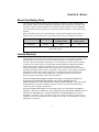
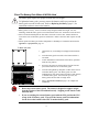
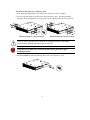
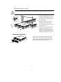
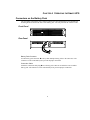
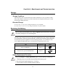
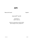
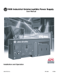
User’s Manual English APC Smart-UPS 2U Rack and Stack External Battery Pack 990-1022, Revision 1 5/00 Entire contents copyright © 2000 by American Power Conversion Corporation. All rights reserved. Reproduction in whole or in part without permission is prohibited. APC, Smart-UPS, and PowerChute are registered trademarks of American Power Conversion Corporation. All other trademarks are the property of their respective owners. 990-1022, Revision 1 5/00 Table of Contents Chapter 1: Safety Information..............................................................1 Conventions Used in this Manual..........................................................1 Handling Safety .....................................................................................1 Electrical Safety.....................................................................................2 Deenergizing Safety ..............................................................................2 Battery Safety ........................................................................................2 Replacement and Recycling of Batteries...............................................2 Chapter 2: Basics....................................................................................3 About Your Battery Pack.......................................................................3 Limited Warranty ..................................................................................3 How To Contact APC............................................................................4 North America ...................................................................................4 Latin America ....................................................................................4 Chapter 3: Installing Your Battery Pack .............................................5 Unpacking..............................................................................................5 Inspection...........................................................................................5 Contents .............................................................................................5 Placement...........................................................................................5 How to Install a Battery Pack ................................................................5 Place The Battery Pack Where It Will Be Used ................................6 Attach the Front Bezel .......................................................................9 Connect the Battery Pack(s) to the Smart-UPS................................10 Chapter 4: Operating the Smart-UPS................................................11 Connectors on the Battery Pack...........................................................11 Front Panel .......................................................................................11 Rear Panel ........................................................................................11 How to Set the Smart-UPS to Recognize the Battery Pack(s).............12 Chapter 5: Maintenance and Troubleshooting..................................15 Storage.................................................................................................15 Storage Conditions...........................................................................15 Extended Storage .............................................................................15 Replacing the Battery ..........................................................................15 Battery Replacement Procedure.......................................................15 Service .................................................................................................17 Appendix A: Specifications .................................................................19 Regulatory Agency Approvals ............................................................19 990-1022, Revision 1 5/00 CHAPTER 1: SAFETY INFORMATION This Safety Guide contains important instructions that should be followed during the installation and maintenance of the APC equipment and batteries. It is intended for APC customers who setup, install, relocate, or maintain APC equipment. Conventions Used in this Manual This section defines the symbols used throughout this manual. Carefully read all information boxes and abide by the instructions. The WARNING sign denotes a serious hazard. It calls attention to a procedure, practice, condition, or the like, which, if not correctly performed or adhered to, could result in injury to personnel. The CAUTION sign denotes a hazard. It calls attention to an operating procedure, practice, or the like, which, if not correctly performed or adhered to, could result in damage to or destruction of all or part of the product. The NOTE sign denotes important information. It calls attention to a procedure, practice, condition, or the like, which is essential to highlight. Handling Safety • Be careful. Do not lift heavy loads without assistance. 32 – 55 kg (70 – 120 lb) <18 kg (<40 lb) 18 – 32 kg (40 – 70 lb) >55 kg (>120 lb) • Equipment with casters is built to move on a smooth surface without any obstacles. • Do not use a ramp inclined at more than 10°. • This equipment is intended for installation in a temperature-controlled indoor area (see Appendix A: Specifications, page 19, for exact temperature range), free of conductive contaminants. 1 Electrical Safety • To reduce the risk of fire, connect only to a circuit provided with a 20 Amp maximum branch circuit overcurrent protection in accordance with the National Electrical Code ANSI/NFPA. • Do not work alone under hazardous conditions. • Check that the power cord(s), plug(s), and sockets are in good condition. Deenergizing Safety • If the equipment has an internal energy source (the battery), the output may be energized when the unit is not connected to an AC power outlet. • To deenergize pluggable equipment: first press the Off button for more than one second to switch the equipment off. Next disconnect the equipment from the AC power outlet. Finally, disconnect the battery. • Pluggable equipment includes a protective earth conductor which carries the leakage current from the load devices (computer equipment). Total leakage current must not exceed 3.5 mA. • Use of this equipment in life support applications where failure of this equipment can reasonably be expected to cause the failure of the life support equipment or to significantly effect its safety or effectiveness is not recommended. Battery Safety • This equipment contains potentially hazardous voltages. Do not attempt to disassemble the unit. The only exception is for equipment containing batteries. Battery replacement using the procedures below is permissible. Except for the battery, the unit contains no user serviceable parts. Repairs are performed only by factory trained service personnel. • Do not dispose of batteries in a fire. The batteries may explode. • Do not open or mutilate batteries. They contain an electrolyte which is toxic and harmful to the skin and eyes. • To avoid personal injury due to energy hazard, remove wrist watches and jewelry such as rings when replacing the batteries. Use tools with insulated handles. • Replace batteries with the same number and type of batteries as originally installed in the equipment. Replacement and Recycling of Batteries See your dealer or Replacing the Battery, page 15, for information on replacement battery kits and battery recycling. 2 CHAPTER 2: BASICS About Your Battery Pack This APC 2U Rack and Stack Battery Pack is designed to connect to an APC Uninterruptible Power Supply (UPS) to provide extended protection from electrical blackouts, brownouts, sags, and surges. This protection safeguards your computer and other valuable electronic equipment. The external battery pack also provides extra protection while the batteries in the UPS are being replaced. Refer to the table below for the maximum number of battery packs supported by the UPS. In addition, battery pack connectors are color coded and keyed to prevent improper connection. UPS Voltage Uses this Battery Pack (connector color) Maximum Number of Battery Packs SU1400 3U 24 Vdc Gray* 10 * Connector is larger than, and not interchangeable with, the 24 Vdc gray connector used on other battery packs. Limited Warranty American Power Conversion (APC) warrants its products to be free from defects in materials and workmanship for a period of two years from the date of purchase. Its obligation under this warranty is limited to repairing or replacing, at its own sole option, any such defective products. To obtain service under warranty you must obtain a Returned Material Authorization (RMA) number from customer support (see Service, page 17). Products must be returned with transportation charges prepaid and must be accompanied by a brief description of the problem encountered and proof of date and place of purchase. This warranty does not apply to equipment which has been damaged by accident, negligence, or misapplication or has been altered or modified in any way. This warranty applies only to the original purchaser who must have properly registered the product within 10 days of purchase. EXCEPT AS PROVIDED HEREIN, AMERICAN POWER CONVERSION MAKES NO WARRANTIES, EXPRESSED OR IMPLIED, INCLUDING WARRANTIES OF MERCHANTABILITY AND FITNESS FOR A PARTICULAR PURPOSE. Some states do not permit limitation or exclusion of implied warranties; therefore, the aforesaid limitation(s) or exclusion(s) may not apply to the purchaser. EXCEPT AS PROVIDED ABOVE, IN NO EVENT WILL APC BE LIABLE FOR DIRECT, INDIRECT, SPECIAL, INCIDENTAL, OR CONSEQUENTIAL DAMAGES ARISING OUT OF THE USE OF THIS PRODUCT, EVEN IF ADVISED OF THE POSSIBILITY OF SUCH DAMAGE. Specifically, APC is not liable for any costs, such as lost profits or revenue, loss of equipment, loss of use of equipment, loss of software, loss of data, costs of substitutes, claims by third parties, or otherwise. 3 How To Contact APC Internet http://www.apcc.com/contact North America Phone Fax 1.800.800.4272 1.401.788.2743 Latin America Argentina Brazil Colombia Mexico Uruguay Venezuela Email 0800.9.APCC (0800.9.2722) 0800.12.72.21 980.15.39.47 95.800.804.4283 000.413.598.2139 8001.2856 [email protected] If you ordered a Smart-UPS SU1400RMXL3UX171 unit, please refer to the red addendum sheet (part number 990-1023) for contact information. 4 CHAPTER 3: INSTALLING YOUR BATTERY PACK Unpacking APC has taken care to design robust packaging for your product. However, accidents and damage may occur during shipment. Inspection Inspect the UPS upon receipt. Notify the carrier and dealer if there is damage. The packaging is recyclable; save it for reuse or dispose of it properly. Contents The shipping package contains the battery pack, its front panel bezel, mounting rails, and a literature kit (containing mounting hardware, and product documentation). Placement S m a r t - U P S S m a r t - U P S S m a r t - U P Install the battery pack in a protected area that is free of excessive dust and has adequate air flow. Do not operate the battery pack where the temperature and humidity are outside the specified limits. S Changes or modifications to this unit not expressly approved by the party responsible for compliance could void the warranty. How to Install a Battery Pack To install one or multiple battery packs, follow these steps: 1. Place the battery pack where it will be used. (This step includes mounting the battery pack(s) in the rack, if desired.) 2. Attach the front bezel. 3. Connect the battery pack to the Smart-UPS or another battery pack. This section describes each step in detail. 5 Place The Battery Pack Where It Will Be Used The battery pack requires two people to install due to its weight. To lighten the battery pack, you may remove the batteries while you position the battery pack or mount it in the rack. Refer to Replacing the Battery, page 15, for instructions on how to remove the batteries. • Battery packs are heavy. Select a location sturdy enough to handle the weight. For rack mounting, install the battery pack at or near the bottom of the rack. Position it below the UPS. • Select a location with adequate air flow that is free from excessive dust. Ensure that the air vents on the sides of the battery pack are not blocked. Allow at least one inch of space on both sides. • Do not operate the battery pack where temperature or humidity are outside the limits listed in Appendix A: Specifications, page 19. To Stack the Units bottom 1. Unpack the six (6) mounting feet (shipped in the literature kit). 2. Turn the battery pack on its side so the bottom surface is accessible. 3. Locate indentations on the bottom of the battery pack that mark the feet position. 4. Peel away the protective film on the back of the feet and press hard to affix the feet to the battery pack. 5. Turn the unit rightside up and place it either on the floor or on another battery pack. The battery pack cover has indentations for feet on the bottom of either a UPS (shown) or another battery pack. You can stack up to ten (10) battery packs and one UPS in a single stack. 6. Skip to Attach the Front Bezel, page 9, to complete the installation. B a tte r y P a c k | 0 B a tte r y P a c k • Do not step on the battery pack! The chassis is designed to support weight from the location of the feet indentations only. Stepping on the chassis could crush the unit. • If you are stacking the external battery pack with the UPS, position the UPS on top of the 2U battery pack. The top of the battery pack has indentations for the feet on the bottom of the UPS or another battery pack. 6 To Mount the Battery Pack in a Rack The battery pack comes with standard 19-inch (46.5 cm) rack mount brackets (in the literature kit) and mounting rails and cleats. There are three steps to install the battery pack in a rack. Each step is explained in this section. 1. Install the mounting rails in the rack. 2. Attach the mounting brackets to the battery pack. 3. Slide the battery pack into the rack and fasten the mounting brackets. Install the Mounting Rails in the Rack The mounting rails are designed to fit a four-post rack. The rack can have any of the common types of equipment mounting holes (square, round-threaded, or round-nonthreaded). All necessary hardware is provided. If you are using a two-post rack, use the mounting brackets alone to mount the UPS. Position the mounting brackets in the setback position. 5 2 1 1. Determine where in the rack you will mount the battery pack. Each battery pack requires a space of 2U. Some racks have tick marks to indicate the U-spaces. 2. Locate the designated U-space and, counting from the bottom, mark holes 1, 2, and 5 on each front post. 3. Align the bottom hole on the mounting rail with the bottom hole in the U-space (hole 1). Position the rails so that the lip of the rail is on the inside bottom. 4. Insert a flat, Phillips head screw (10-32) and conical washer into the second hole from the bottom (hole 2) of the U-space. 5. Insert another screw and washer into hole 5 to securely attach the front rail to the rack. 6. Expand the rail so that it spans from the front rack post to the back rack post. 7. Use two screws and washers to attach the rail to the back rack post. Use the same hardware (10-32 flat head screws and conical washers) used in step 4. 8. Repeat steps 3 through 7 for the other rail. 5 2 1 5 2 Left Front Rack Post Right Rear Rack Post 7 Attach the Mounting Brackets to the Battery Pack • Each mounting bracket attaches to the battery pack with four (4) screws, included. • Two sets of bracket holes are located on the sides of the battery pack. Attach the mounting brackets in the forward position for a four-post rack or the setback position for a two-post rack. Bracket Position for a Four-Post Rack Bracket Position for a Two-Post Rack If you are using a two-post rack, reposition the mounting brackets to the setback position before mounting the battery pack in your rack. Check the rack to make sure it will not tip after moving the battery pack mounting brackets. • For Four-Post Racks: Attach a mounting cleat to each side of the battery pack. 8 Slide the Battery Pack in the Rack Due to the weight of the battery pack, two people are required to install it in the rack. 1. Using the handles on the side of the battery pack, carefully align the unit with the rails. Slide the battery pack into position. 2. Each side of the battery pack has a cleat that must slide into the groove on the rails. Slide the battery pack into position. 3. Use the four (4) ornamental screws supplied with the battery pack to attach the mounting brackets to the rack post. Insert the screws into the top and bottom holes in the U-space. Attach the Front Bezel Unpack the front panel bezel and hold it with the cutout section on the right. Align the tabs on the side of the bezel with the slots on the front of the battery pack and firmly snap it into place. 9 Connect the Battery Pack(s) to the Smart-UPS Battery pack connectors are color coded and keyed to prevent improper connection. The color of the connector on the UPS must match the color of the battery pack connector. Allow the battery pack to charge for 24 hours. Do not expect full run time during this initial charge period. Refer to About Your Battery Pack, page 3, for the type of UPS that supports this battery pack and the maximum number of battery packs that can be connected to a UPS. 1. Prepare the UPS to connect the battery pack(s). Note the holes used to attach the battery pack connector clamp (near the center of the connector opening). Use a Phillips head screwdriver to remove the battery pack connector clamp from the back of the UPS. 2. Turn the clamp over and loosely attach one end at the edge of the connector opening in the UPS. 3. Holding the clamp aside, insert the battery pack connector into the UPS. 4. Secure the connector clamp. ® M A D E I N S U X X 0 1 2 3 4 1 4 0 0 R U M S X A ( W E S T K IN G S T O N , R I ) L 3 U 5 6 7 8 9 Two battery packs correctly connected to a Smart-UPS XL. 10 CHAPTER 4: OPERATING THE SMART-UPS Connectors on the Battery Pack The front panel of the battery pack contains a simple bezel (for identification). The optional rack mounting brackets attach to the sides of the battery pack. The rear panel has the connector cable. Front Panel BATTERY PAC K Rear Panel Battery Pack Connector Use the battery pack connector to daisy-chain multiple battery packs to the same UPS. The connector is color-coded and keyed to prevent improper connection. Connection Cable Attach the connection cable plug into a battery pack connector on either the UPS or another battery pack. The connector is color-coded and keyed to prevent improper connection. 11 How to Set the Smart-UPS to Recognize the Battery Pack(s) Smart-UPS XL models cannot determine how many external battery packs are connected to them. You must program the Smart-UPS XL with the appropriate number of external batteries in one of four ways. It is important to follow these instructions. The number of batteries affects the run time calculations which Smart-UPS performs when it is running on battery power. Use the Smart-UPS Battery Pack Utility (BATTPACK) This program can be used with DOS or at a Microsoft® Windows DOS prompt. BATTPACK cannot be used with a DOS emulator or VDM (virtual DOS machine) like those in Windows 95, Windows 98, or Windows NT. The APC UPS Link cable must be used to communicate to the UPS. There are two black cables which can be used; part numbers 940-0024C or 940-1524C. At the DOS prompt, type: battpack com[X] [Y] where: [X] represents the available serial port that Battery Pack Utility uses to access the Smart-UPS. [Y] represents the number of external battery packs. For example: C:> battpack com1 4 The black cable is attached to communication port 1. There are four external battery packs. The program confirms that the update is successful. Use PowerChute® plus Version 5.x for Windows 95, Windows 98, Windows NT PowerChute plus 5.x for Windows NT is compatible with NT 3.5.1 SP5, NT 4.0 Workstation (at least SP1), or NT 4.0 Server (at least SP1). Install the software per the instructions on the CD. After rebooting the computer, access the PowerChute plus graphical user interface. 1. Click on Configuration. 2. Click on UPS Operating Parameters. 3. Adjust the External Battery Pack field to the appropriate number of external battery packs. 4. Click OK. 12 Use the Terminal Program to Change the Number of External Battery Packs Terminal is used in Windows 3.1x, Windows for Workgroups, and Windows NT 3.51. 1. EXIT out of the PowerChute plus Server. In the case of Windows NT, the UPS Service must be stopped. 2. Go to: Program Manager > Accessories > Terminal. Double-click on the Terminal icon. 3. Select the COM port to which the black-colored interface cable is attached as the Connector. 4. The COM port settings are 2400 baud, 8 data bits, 1 stop bit, no parity, flow control is Xon/Xoff. 5. Click OK. 6. Continue with the table in Step 7 in Use the HyperTerminal Program to Change the Number of External Battery Packs, page 14. 13 Use the HyperTerminal Program to Change the Number of External Battery Packs HyperTerminal is used for Windows 95, Windows 98, and Windows NT 4.0 1. EXIT out of the PowerChute plus Server. In the case of Windows NT, the UPS service must be stopped. 2. From the Desktop, go to: Start => Programs => Accessories => HyperTerminal. Doubleclick on the HyperTerminal icon. 3. You are prompted to choose a name and select an icon. Give any name and then click OK. If a message appears which reads “...must install a modem,” disregard it and continue. 4. The port settings are 2400 baud, 8 data bits, 1 stop bit, no parity, flow control is Xon/Xoff. 5. Click on Advanced and ensure the box labeled FIFO buffer is NOT checked. 6. Click OK twice. 7. Once the terminal/hyperterminal window is open, follow these steps: Step Number Command Response 1 Y SM 2 > To see the number of external packs. (A new unit will display 000.) 3 + Adds a battery pack. 4 > To see the change in number of external battery packs. 5 - Subtracts a battery pack. 6 > To see the change in number of external battery packs. 14 CHAPTER 5: MAINTENANCE AND TROUBLESHOOTING Storage Storage Conditions Store the battery pack covered and flat (rack mount orientation) in a cool, dry location, with its battery fully charged. Disconnect any cables connected to the computer interface port to avoid unnecessarily draining the battery. Extended Storage At -15 to +30 °C (+5 to +86 °F), charge the batteries every six months. At +30 to +45 °C (+86 to +113 °F), charge the batteries every three months. Replacing the Battery The 2U battery pack and Smart-UPS 1400 use different replacement battery cartridges. The battery cartridges are not interchangeable This battery pack consists of two easy to replace hot-swappable battery trays. Battery replacement is a safe procedure, isolated from electrical hazards. You may leave the battery pack connected to the UPS and the protected equipment on for the following procedure. See your dealer or APC (refer to How To Contact APC, page 4) for information on replacement battery trays. Unit Replacement UPS SU1400RMXL3U RBC25 External battery pack SU24RMXLBP2U RBC26 Shape Battery Replacement Procedure Please read Chapter 1: Safety Information, page 1, before replacing a battery tray. 1. The battery trays are accessible from the front of the battery pack. 2. Be careful removing the battery tray—it is heavy. 3. This procedure requires a Phillips head screwdriver. 15 1. Face the front of the battery pack and, using both hands, insert each index finger behind the lip of the curved section of the front bezel and pull towards you. The front bezel will unsnap. 2. Set the bezel aside. The two battery compartments will be visible. 3. Use a screwdriver or coin to remove the two (2) screws and open the door. The door is hinged in the center of the chassis. 4. Take out the white cord, which is tucked into the space above the battery tray handle. Grasp the cord and pull firmly towards you to disconnect the battery. 5. Use the battery tray handle to slide the tray out most of the way (when all four batteries are visible). Then support the tray from the sides and lift the back of the tray over the stops . 6. Return the battery tray to APC. (Refer to How To Contact APC, page 4, for information.) The battery replacement kit includes two new battery trays. 7. Hold the new tray on the sides, align it with the opening, and lift it slightly to clear the stops. Then level the battery tray and slide it into the unit. Remove the tape on the new battery tray connector to expose the cable connector. Locate the battery connector which is to the side of the battery tray and recessed. Connect the battery cable connector to the connector. Press firmly to ensure that the connection is tight. You will hear a “snap” when the connector is properly seated. Tuck the white battery cable cord neatly into the space above the battery tray handle. Close the door and replace the two (2) screws removed in step 3. Repeat steps 3 through 11 to replace the second battery tray. Align the tabs the front panel bezel with the slots on the front of the battery pack and firmly snap it into place. 8. 9. 10. 11. 12. 13. 16 Service If the battery pack requires service do not return it to the dealer! Follow these steps: 1. Verify that no circuit breakers are tripped. A tripped circuit breaker is the most common problem! 2. If the problem persists, call customer service or visit the APC Internet Website (www.apcc.com). • 3. Note the model number of the battery pack, the serial number, and the date purchased. A technician will ask you to describe the problem and try to solve it over the phone, if possible. If this is not possible the technician will issue a Returned Material Authorization Number (RMA#). • If the battery pack is under warranty, repairs are free. If not, there is a repair charge. Pack the battery pack in its original packaging. If the original packing is not available, ask customer service about obtaining a new set. Pack the battery pack properly to avoid damage in transit. Never use Styrofoam beads for packaging. Damage sustained in transit is not covered under warranty. 4. Mark the RMA# on the outside of the package. 5. Return the UPS by insured, prepaid carrier to the address given to you by Customer Service. 17 18 APPENDIX A: SPECIFICATIONS 2U Battery Pack (SU24RMXLBP2U) Battery type Spill proof, maintenance free, sealed lead-acid Typical battery life 3 – 6 years, depending on number of discharge cycles and ambient temperature Operating temperature 0 to +40 ºC (+32 to +104 ºF) Storage temperature -15 to +45 ºC (+5 to +113 ºF) Operating and storage relative humidity 0 to 95%, non-condensing Operating elevation 0 to +3,000 m (0 to +10,000 ft) Storage elevation 0 to +15,000 m (0 to +50,000 ft) Size (H x W x D) 3.37 in. x 17 in. x 19 in. (8.6 cm x 43.2 cm x 48.3 cm) Weight - net (shipping) 66 lb (80 lb) 29.9 kg (36.6 kg) Safety approvals Listed to UL 1778, certified to CSA 107.1 EMI verification FCC/DOC Class A certified Due to continuous research and development activities, specifications are subject to change without notice. Regulatory Agency Approvals ® LISTED 42C2 E95463 LR63938 19