1
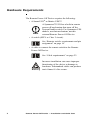
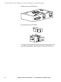
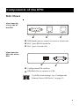
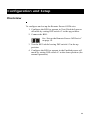
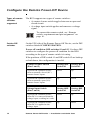
Remote Power-Off
Device
AP9830
Installation and
Quick Start
Contents
Features and Requirements 1
Features . . . . . . . . . . . . . . . . . . . . . . . . . . . . . . . . 1
Hardware Requirements . . . . . . . . . . . . . . . . . . . . 2
Safety Information 3
Avoid Hazardous Configurations . . . . . . . . . . . . . . 3
Example of the potential hazard 3
Accessory devices that can override the RPO 3
Eliminate the Hazard . . . . . . . . . . . . . . . . . . . . . . 4
Use an Emergency Power Off system 4
Block access to accessory devices 5
Contact Closure Setup with Multiple UPSs . . . . . . . 6
Verify Contents of the Shipment 7
Unpack and Inspect the RPO Package . . . . . . . . . . 7
Please recycle 7
Receiving inspection 7
Components of the RPO 9
Side Views . . . . . . . . . . . . . . . . . . . . . . . . . . . . . . 9
View from the server side of the RPO 9
View from the UPS side of the RPO 9
Top View . . . . . . . . . . . . . . . . . . . . . . . . . . . . . . 10
Configuration and Setup 11
Overview . . . . . . . . . . . . . . . . . . . . . . . . . . . . . . 11
Configure the Remote Power-Off Device . . . . . . . 12
Types of remote switches supported 12
Remote Power-Off Device — Installation and Quick Start
Contents
Set up the Remote Power-Off Device . . . . . . . . . . 14
Remote switch: requirements and pin assignment 16
Pin locations for the keystone jack 16
Pin locations for the RJ -11 connector 16
Connect the switch cable to the keystone jack 17
Placement of accessories 19
How to Turn Off the Output of Multiple UPSs . . . 20
Cascade multiple RPOs (serial setup) 20
Matrix-UPS® in a cascading configuration 21
Connect multiple RPOs in parallel setup (voltage input
switches only) 21
Product Information 22
Selecting and Ordering Components. . . . . . . . . . 22
Remote switch specifications 22
Cable requirements 22
Ordering components 22
Product Specifications . . . . . . . . . . . . . . . . . . . . . 23
Warranty and Service . . . . . . . . . . . . . . . . . . . . . 24
Limited warranty 24
Warranty limitations 24
Obtaining service 24
Life-Support Policy . . . . . . . . . . . . . . . . . . . . . . . 26
General policy 26
Examples of life-support devices 26
Radio Frequency Interference . . . . . . . . . . . . . . . 27
ii
Remote Power-Off Device — Installation and Quick Start
Features and Requirements
Features
The APC® Remote Power-Off Device (RPO), AP9830,
enables you to turn off the output power of an APC
uninterruptible power supply (UPS) immediately by a remote
switch. For example:
• If the UPS itself is not readily accessible, place the RPO
in a convenient location.
• To turn off the output power of more than one UPS
remotely by a single switch, set up each UPS with its
own RPO.
See “How to Turn Off the Output of Multiple
UPSs” on page 20.
The Remote Power-Off Device works with a variety of
switches – normally open, normally closed, and applied
voltage – and supports all functions normally available to the
UPS, including the following:
• Applying power to accessories
• Smart-signaling (advanced signaling)
• UPS Turn-on
• UPS Turn-off
1
Hardware Requirements
The Remote Power-Off Device requires the following:
• A Smart-UPS® or Matrix-UPS™.
Note
A Symmetra™ UPS has a built-in remote
power-off mechanism that turns off the
System Enable switch. For Symmetra UPS
models, use that mechanism, not this
external Remote Power-Off Device.
• A switch (SELV or Class 2 circuit).
See “Remote switch: requirements and pin
assignment” on page 16.
• A cable to connect the remote switch to the Remote
Power-Off Device.
See “Cable requirements” on page 22.
Warning
2
Incorrect installation can cause improper
functioning of the device or damage to
hardware. Substandard cables can produce
toxic fumes if a fire occurs.
Remote Power-Off Device — Installation and Quick Start
Safety Information
Avoid Hazardous Configurations
Example of the
potential hazard
1. An administrator uses the remote switch connected to the
Remote Power-Off Device to turn off the output power
from a UPS, but the UPS continues to receive utility
power.
2. From an interface of an APC accessory device, a user
issues a command for the UPS to begin providing output
power.
3. Although the remote switch connected to the Remote
Power-Off Device is off, the UPS provides output power
briefly and then turns off again, providing output power
that is potentially dangerous to anyone servicing attached
devices.
Accessory
devices that can
override the
RPO
The following APC accessories can cause a brief override to a
a UPS output turnoff initiated by the Remote Power-Off
Device:
• Network Management Card (AP9617, AP9618, AP9619)
Note
In many case, an APC accessory device has a
built-in Network Management Card, which
does not have its own separate part number.
• PowerView (AP9215), the display interface on many
APC products
• Out-of-Band Management Card (AP9608)
• Two devices that are no longer sold by APC but that
might still be a part of your system:
– Web/SNMP Management Card (AP9606)
– PowerNet SNMP Adapter (AP9605)
3
Eliminate the Hazard
Warning
Use an
Emergency
Power Off
system
If brief periods of UPS output power (when the
remote switch is off) can cause personal injury
or damage to hardware or data, do not use the
Remote Power-Off Device as the only means of
controlling UPS output power.
Matrix-UPS models and many Smart-UPS models have an
integrated EPO system that allows connected equipment to be
deenergized immediately from a remote location without the
UPS switching to battery operation.
Electrical
Hazard
The Remote Power-Off Device does not provide
full Emergency Power-Off (EPO) protection. For
full EPO protection, connect the Remote PowerOff Device to an EPO system that removes utility
power from the UPS when engaged.
To set up the integrated EPO system of an APC
UPS, see the manual provided with the UPS.
See also
Warning
4
To avoid damage to the UPS, connect its EPO
system only to Safety Extra Low Voltage
(SELV) circuits that are contact-closure
circuits.
Remote Power-Off Device — Installation and Quick Start
Safety Information: Eliminate the Hazard
Block access to
accessory
devices
The Remote Power-Off Device can provide a useful alternative
to the integrated EPO interface of a UPS in any of the
following situations:
• Your system configuration requires either of the
following to turn off the output from the UPS:
– a switched-voltage signal (instead of a contact
closure)
– a normally closed contact closure
• A limited number of contact closures is available at the
remote EPO interface for turning off the output of
multiple UPSs.
If you cannot use an EPO system with your Remote Power-Off
Device, block access to any accessory device that could
override the RPO.
Electrical
Hazard
You must prevent users from inadvertently
using accessory devices to turn on the UPS if
you cannot remove utility power from the UPS
and if it is essential that the RPO continue to
keep the UPS output power turned off.
You can block access to accessory devices in the following
ways:
• To block access by all accessories that could briefly
override the RPO over a network connection, plug the
network router (or concentrator) into the UPS. With this
setup, turning off output power to the UPS turns off
power to the network connection to the UPS.
• To prevent users from issuing UPS turn-on commands
from specific APC accessory devices:
– PowerView display interface: Limit users’ access to
this accessory device.
– Network Management Card, Web/SNMP
Management Card, or PowerNet SNMP Adapter:
Remove the Ethernet cable.
– Network Management Card EM/MDM (AP9618):
Unplug the telephone cable.
– Out-of-Band Management Card: Disconnect the
modem connection.
Remote Power-Off Device — Installation and Quick Start
5
Contact Closure Setup with Multiple UPSs
Warning
To connect multiple UPSs to a system that uses
contact closures to turn off the UPSs, you must
provide a separate set of contact closures for
each UPS. Do not set up multiple UPSs in a
parallel configuration to a single set of contacts.
A parallel configuration can introduce
intersystem ground noise or generate false EPO
signals at the integrated EPO interface of a
UPS or at the Remote Power-Off Device.
To eliminate the need for multiple contact closures at the
remote switch, do one of the following:
• Use an applied voltage switch.
• Use a cascading setup.
See “Cascade multiple RPOs (serial setup)”
on page 20.
Note
6
You can include only one APC Matrix-UPS
in a cascading configuration, and you must
place it at the end of the series of UPSs.
Remote Power-Off Device — Installation and Quick Start
Verify Contents of the Shipment
Unpack and Inspect the RPO Package
Please recycle
Receiving
inspection
The shipping materials are recyclable. Please
save them for later use, or dispose of them
appropriately.
Inspect the package and contents for shipping damage, and
make sure that all parts were sent. Report any damage
immediately to the shipping agent, and report missing contents,
damage, or other problems immediately to APC or your APC
reseller.
Check to be sure that you received all the following items:
• DB9-DB9 Cable (940-0064)
• RJ-11 Cable, 10 ft (607-0035)
• RJ-11 Cable, 6 in. (607-0036)
7
Verify Contents of the Shipment: Unpack and Inspect the RPO Package
• Remote Power-Off Device
• Keystone jack (750-0023)
• A strip of hook-and-loop fastener (not shown here) for
optional mounting of the Remote Power-Off Device.
8
Remote Power-Off Device — Installation and Quick Start
Components of the RPO
Side Views
View from the
server side of
the RPO
DB9 female port to connect to server or accessories
RJ-11 port: RPO/Cascade In
RJ-11 port: Cascade Out
View from the
UPS side of the
RPO
1 2 3 4
Configuration DIP switches
DB9 Male Port to connect to UPS
For DIP switch settings, see “Configure the
Remote Power-Off Device” on page 12.
9
Top View
10
Power-Off/Test LED
Labels that identify components on the sides of the RPO
Remote Power-Off Device — Installation and Quick Start
Configuration and Setup
Overview
To configure and set up the Remote Power-Off Device:
1. Configure the RPO to operate in Test (Disabled) poweroff mode by setting DIP switch #3 to the up position.
2. Connect the RPO.
See “Set up the Remote Power-Off Device”
on page 14.
3. Test the RPO while leaving DIP switch #3 in the up
position.
4. Configure the RPO to operate in the Enabled power-off
mode by setting DIP switch #3 to the down position (for
normal operation).
11
Configure the Remote Power-Off Device
Types of remote
switches
supported
The RPO supports two types of remote switches:
• A contact closure switch toggles between an open and
closed circuit.
• A voltage input switch applies and removes a voltage
signal.
To connect the remote switch, see “Remote
switch: requirements and pin assignment” on
page 16.
Set the DIP
switches
On the UPS side of the Remote Power-Off Device, set the DIP
switches labeled CONFIGURATION.
Power-off condition: DIP switches #1 and #2. Use these DIP
switches to configure the power-off condition for the RPO
according to the type of remote switch it is using.
If the positions of DIP switch #1 and DIP switch #2 are both up
or both down, the configuration is invalid.
12
Contact Closure Switch
(Pins 2 and 5)
Setting: DIP
Switch #1
Setting: DIP
Switch #2
A power-off condition occurs
when a normally closed (NC)
contact closure opens.
down
up
A power-off condition occurs
when a normally open (NO)
contact closure opens.
up
down
Voltage Input Switch
(Pins 3 and 4)
Setting: DIP
Switch #1
Setting: DIP
Switch #2
A power-off condition occurs
when 24 V is removed from the
voltage input, resulting in 0 volts.
down
up
A power-off condition occurs
when 24 V is applied to the
voltage input.
up
down
Remote Power-Off Device — Installation and Quick Start
Configuration and Setup: Configure the Remote Power-Off Device
Power-off mode: DIP switch #3. In either power-off mode,
the Remote Power-Off Device LED illuminates when the
device is connected and configured properly and the remote
switch is being asserted.
Power-Off
Mode
Setting: DIP
Switch #3
Test
(Disabled)
up
Checks wiring
between the
remote switch and
the RPO
No
Enabled
down
Normal operation
Yes
Purpose
Power-Off
Asserted
DIP Switch #4. DIP switch #4 is unassigned.
Remote Power-Off Device — Installation and Quick Start
13
Set up the Remote Power-Off Device
Connect single
and multiple
RPOs
You can connect one Remote Power-Off Device to one remote
switch to control one UPS, or you can connect multiple
Remote Power-Off Devices to one remote switch to control
multiple UPSs simultaneously.
• To connect one Remote Power-Off Device, use the
instructions in this section.
After setup, continue with step 3 of the
procedure in “Overview” on page 11.
• To set up multiple Remote Power-Off Devices with one
remote switch, use this section for basic information on
wiring.
In addition to this section, see “How to Turn
Off the Output of Multiple UPSs” on
page 20.
14
Remote Power-Off Device — Installation and Quick Start
Configuration and Setup: Set up the Remote Power-Off Device
Note
In the following set-up diagram, note that the
RJ-11 cable connects to the middle port, labeled
RPO / Cascade In.
APC UPS
Keystone jack
Wiring to remote switch
Server
Cable provided with UPS software
RJ-11 cable
Remote Power-Off Device
Cable supplied with Remote Power-Off Device
Remote Power-Off Device — Installation and Quick Start
15
Configuration and Setup: Set up the Remote Power-Off Device
Remote switch:
requirements
and pin
assignment
RPO/Cascade In
Pin Assignment
Type
Requirements
Contact
Closure
• Safety Extra Low Voltage
(SELV) or Class 2 circuit
• Switch or relay properly
isolated from the utility
• Latching
2 and 5
Voltage
Input
• SELV or Class 2 circuit
• Switched 24 V AC/DC
• Latching
3 and 4
Pin locations for
the keystone
jack
3
1
2
5
4
6
Pin locations for
the RJ-11
connector
23
45
16
Remote Power-Off Device — Installation and Quick Start
Configuration and Setup: Set up the Remote Power-Off Device
Connect the
switch cable to
the keystone
jack
1. Strip the cable jacket (the outer insulation of the cable) to
expose 1 inch (25.4 mm) of the insulated wires
(unstripped 26 – 22 AWG required).
2. Cut one of the two wires so that only .188 inches (4.76
mm) remain exposed.
3. Choose your wiring scheme according to the type of
remote switch (contact closure or voltage input) that you
are using. A contact closure switch uses pins 2 and 5, and
a voltage input switch uses pins 3 and 4.
4. Place the end of each wire against the back of the
appropriate slot in the clear plastic cap of the keystone
jack.
– The numbers next to the cylinders on the keystone
jack match the pin assignments. Use these numbers to
identify which slots in the plastic cap to use for your
wiring scheme. The illustrations in this procedure
show the wiring scheme for a contact closure switch
(cylinders 2 and 5). A voltage input switch uses
cylinders 3 and 4, the middle cylinder in each of the
two rows of cylinders.
For an illustration of the cylinders and their
numbers, see “Remote switch:
requirements and pin assignment” on
page 16.
– Use the short wire for the appropriate slot in the first
row, and use the long wire for the appropriate slot in
the second row.
Remote Power-Off Device — Installation and Quick Start
17
Configuration and Setup: Set up the Remote Power-Off Device
5. Press each wire into its slot on the clear plastic cap. Then
inspect the cap to ensure that each wire is in the correct
slot and that the end of each wire touches the back of the
slot.
6. Press the plastic cap, with the wires connected, onto the
cylinders of the keystone jack.
18
Remote Power-Off Device — Installation and Quick Start
Configuration and Setup: Set up the Remote Power-Off Device
7. Using slip-joint pliers, terminate the wires by pressing
the plastic cap and keystone jack together until the cap
snaps into place.
8. Inspect the jack to ensure that the cap is securely snapped
into place and that both wires are terminated.
Placement of
accessories
The Remote Power-Off Device works with any APC accessory
that is connected to the Remote Power-Off Device through the
DB9 port labeled TO SERVER OR ACCESSORIES.
Caution
Never connect an external APC UPS accessory
between the Remote Power-Off Device and the
UPS. An accessory connected in this manner may
be able to turn on the UPS during a remote poweroff condition.
Remote Power-Off Device — Installation and Quick Start
19
How to Turn Off the Output of Multiple UPSs
To set up more than one APC UPS to turn off from one remote
switch, you must have one Remote Power-Off Device for each
UPS. You can set up remote turnoff of multiple UPS outputs in
either a cascading (serial) configuration or (for voltage input
switches only) a parallel configuration.
Warning
Cascade
multiple RPOs
(serial setup)
To connect multiple UPSs to a system that uses
contact closures to turn off the UPSs, you must
provide a separate set of contact closures for
each UPS. Do not set up multiple UPSs in a
parallel configuration to a single set of contacts.
A parallel configuration can introduce
intersystem ground noise or generate false EPO
signals at the integrated EPO interface of a
UPS or at the Remote Power-Off Device.
You can set up either type of remote switch (contact closure or
voltage input) by cascading Remote Power-Off Devices.
20
UPS 1
UPS 2
UPS n
Connection to remote switch
Remote Power-Off Device — Installation and Quick Start
Configuration and Setup: How to Turn Off the Output of Multiple UPSs
Matrix-UPS® in a
cascading
configuration
You can include only one APC Matrix-UPS in a cascading
configuration, and you must place it at the end of the series of
UPSs (UPS n in the example setup).
Connect
multiple RPOs in
parallel setup
(voltage input
switches only)
You can set up a remote voltage input switch by connecting
multiple Remote Power-Off Devices in parallel.
UPS 1
UPS n
Pin 3
Pin 4
Wiring to voltage input remote switch
RJ-11 cable
Keystone jack
Warning
To avoid equipment damage and false RPO
signals, use a parallel configuration only with a
voltage input remote switch. To connect multiple
RPOs to one contact closure switch, see “Cascade
multiple RPOs (serial setup)” on page 20.
Remote Power-Off Device — Installation and Quick Start
21
Product Information
Selecting and Ordering Components
Remote switch
specifications
Cable
requirements
See “Remote switch: requirements and pin
assignment” on page 16.
You can use the two RJ-11 cables that came with the Remote
Power-Off Device or use existing building cables. The cable
that connects the Remote Power-Off Device to the remote
switch must meet these requirements:
• It must be UL-listed
• Wire size must be 26 – 22 AWG
• Wire type must be one of the following:
– CL2: Class 2 cable for general use
– CL2P: Plenum cable for use in ducts, plenums, or
other space used for environmental air
– CL2R: Riser cable for use in a vertical run in a shaft
or from floor to floor
– CL2X: Limited-use cable for use in dwellings or in
raceway
For installations in Canada, the cable must be CSA certified,
type ELC (extra-low-voltage control cable).
Warning
Ordering
components
22
Incorrect installation can cause improper
functioning of the device or damage to hardware.
Substandard cables can produce toxic fumes if a
fire occurs.
To order additional components, contact APC at a phone
number on the back cover of this manual or order online at the
American Power Conversion Web site, www.apc.com.
Product Specifications
Physical
Dimensions
(H × W × D)
Unit
Shipping
2.54 × 9.53 × 6.05 cm (1.00 × 3.75× 2.38 in)
7.26 × 24.13 × 16.51 cm (2.86 × 9.50 × 6.50 in)
Weight
Unit
Shipping
0.23 kg (0.50 lb)
0.36 kg (0.80 lb)
Distance (cable
3 m, normal; 60 m, maximum
length) between the (10 ft, normal; 200 ft, maximum)
remote switch and
the RPO
Maximum number
of cascading units
10
Electrical
Power required
24 VDC at 35 mA, powered by the UPS port
Environmental
Temperature
Operating
Storage
0° to 45° C (32° to 113° F)
–15° to 65° C (5° to 149° F)
Relative Humidity
Operating
Storage
0 – 95%
0 – 95% non-condensing
Elevation
Operating
Storage
0 – 3000 m (0 – 10 000 ft)
0 – 15 000 m (0 – 50 000 ft)
Approvals
CE, EN 55024, EN 55082
Remote Power-Off Device — Installation and Quick Start
23
Warranty and Service
Limited
warranty
APC warrants the Remote Power-Off Device to be free from
defects in materials and workmanship for a period of two years
from the date of purchase. Its obligation under this warranty is
limited to repairing or replacing, at its own sole option, any
such defective products. This warranty does not apply to
equipment that has been damaged by accident, negligence, or
misapplication or has been altered or modified in any way. This
warranty applies only to the original purchaser.
Warranty
limitations
Except as provided herein, APC makes no warranties,
express or implied, including warranties of merchantability
and fitness for a particular purpose. Some jurisdictions do
not permit limitation or exclusion of implied warranties;
therefore, the aforesaid limitation(s) or exclusion(s) may not
apply to the purchaser.
Except as provided above, in no event will APC be liable
for direct, indirect, special, incidental, or consequential
damages arising out of the use of this product, even if
advised of the possibility of such damage.
Specifically, APC is not liable for any costs, such as lost profits
or revenue, loss of equipment, loss of use of equipment, loss of
software, loss of data, costs of substitutes, claims by third
parties, or otherwise. This warranty gives you specific legal
rights and you may also have other rights, which vary
according to jurisdiction.
Obtaining
service
To obtain support for problems with your Remote Power-Off
Device:
1. Note the serial number and date of purchase. The serial
number is on a label on the bottom of the RPO after the
characters S/N:.
2. Contact Customer Support at a phone number on the
back cover of this manual. A technician will try to help
you solve the problem by phone.
3. If you must return the product, the technician will give
you a return material authorization (RMA) number. If the
24
Remote Power-Off Device — Installation and Quick Start
Product Information: Warranty and Service
warranty expired, you will be charged for repair or
replacement.
4. Pack the unit carefully. The warranty does not cover
damage sustained in transit. Enclose a letter with your
name, address, RMA number and daytime phone
number; a copy of the sales receipt; and a check as
payment, if applicable.
5. Mark the RMA number clearly on the outside of the
shipping carton.
6. Ship by insured, prepaid carrier to the address provided
by the Customer Support technician.
Remote Power-Off Device — Installation and Quick Start
25
Life-Support Policy
General policy
American Power Conversion (APC) does not recommend the
use of any of its products in the following situations:
• In life-support applications where failure or malfunction
of the APC product can be reasonably expected to cause
failure of the life-support device or to affect significantly
its safety or effectiveness.
• In direct patient care.
APC will not knowingly sell its products for use in such
applications unless it receives in writing assurances
satisfactory to APC that (a) the risks of injury or damage have
been minimized, (b) the customer assumes all such risks, and
(c) the liability of American Power Conversion is adequately
protected under the circumstances.
Examples of lifesupport devices
The term life-support device includes but is not limited to
neonatal oxygen analyzers, nerve stimulators (whether used for
anesthesia, pain relief, or other purposes), autotransfusion
devices, blood pumps, defibrillators, arrhythmia detectors and
alarms, pacemakers, hemodialysis systems, peritoneal dialysis
systems, neonatal ventilator incubators, ventilators (for adults
and infants), anesthesia ventilators, infusion pumps, and any
other devices designated as “critical” by the U.S. FDA.
Hospital-grade wiring devices and leakage current protection
may be ordered as options on many APC UPS systems. APC
does not claim that units with these modifications are certified
or listed as hospital-grade by APC or any other organization.
Therefore these units do not meet the requirements for use in
direct patient care.
26
Remote Power-Off Device — Installation and Quick Start
Radio Frequency Interference
This product contains no clocks or oscillators and therefore does not cause
interference.
APC Worldwide Customer Support
Customer support for this or any other APC product is available at no charge in any of the
following ways:
•
Visit the APC Web site to access documents in the APC Knowledge Base and to
submit customer support requests.
– www.apc.com (Corporate Headquarters)
Connect to localized APC Web sites for specific countries, each of which
provides customer support information.
– www.apc.com/support/
Global support searching APC Knowledge Base and using e-support.
•
Contact an APC Customer Support center by telephone or e-mail.
– Regional centers:
–
APC headquarters U.S., Canada
(1)(800)800-4272 (toll free)
Latin America
(1)(401)789-5735 (USA)
Europe, Middle East, Africa
(353)(91)702000 (Ireland)
Japan
(0) 35434-2021
Australia, New Zealand, South
Pacific area
(61) (2) 9955 9366 (Australia)
Local, country-specific centers: go to www.apc.com/support/contact for
contact information.
Contact the APC representative or other distributor from whom you purchased your APC
product for information on how to obtain local customer support.
Entire contents copyright © 2004 American Power Conversion. All rights reserved.
Reproduction in whole or in part without permission is prohibited. APC, the APC logo,
Smart-UPS, Symmetra, and Matrix-UPS are trademarks of American Power Conversion
Corporation and may be registered in some jurisdictions. All other trademarks, product names,
and corporate names are the property of their respective owners and are used for informational
purposes only.
990-0197A
*990-0197A*
01/2004