1
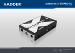
AdderLink DV104T
User Guide
Experts in
Connectivity
Solutions
Video Extension
Solutions
Managing the installation...................................................................................19
Rescanning the System Overview.............................................................19
Changing to an alternative input source..................................................19
Enabling and disabling all screens...............................................................20
Further information
Getting assistance...............................................................................................21
Troubleshooting...................................................................................................22
Appendix A - Cables for use with digital extenders...................................23
Appendix B - Management API specification................................................25
Warranty...............................................................................................................29
Safety information...............................................................................................29
Radio frequency energy.....................................................................................30
CONFIGURATION
Connections...........................................................................................................7
Mounting.................................................................................................................7
Using the rear mounting slot........................................................................7
HDMI connections..........................................................................................8
Using Adder locking HDMI connectors...............................................8
Network connection......................................................................................9
Receiver connections...................................................................................10
Power adapter connection..........................................................................11
Operation
OPERATION
Installation
Initial configuration.............................................................................................12
Accessing the AdderLink POD Manager..................................................12
Using the AdderLink POD Manager.........................................................13
System Overview elements..................................................................13
Receiver configuration...........................................................................14
Transmitter configuration......................................................................15
System configuration..............................................................................17
FURTHER
INFORMATION
Welcome.................................................................................................................2
Operating modes..................................................................................................3
Single source mode.........................................................................................3
Dual source mode...........................................................................................3
AdderLink DV104T features...............................................................................4
Supplied items........................................................................................................5
Optional extras......................................................................................................6
Configuration
Index
INDEX
Introduction
INSTALLATION
Contents
1
Introduction
AdderLink DV104T
Up to 50m
(160 feet)
INDEX
FURTHER
INFORMATION
ALDV100R (HDMI)
or
ALDV120R (DVI-D)
receiver
CONFIGURATION
One or two
HDMI feeds
Ethernet
connection for
configuration and
monitoring
OPERATION
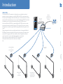
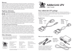
The AdderLink DV104T transmitter is a high performance video/audio switch and
extender that can drive between one and four HDMI (or DVI-D) screens located up to
50 meters away. The intelligent switch within allows you to choose exactly how two video
inputs should be shared between up to four screens. The AdderLink DV104T transmitter
is supplied as part of a kit that also includes four AdderLink DV100R receivers.
Links to the AdderLink DV100R (or optional AdderLink DV120R) receivers are made
using screened twisted pair cables (Category 6 FTP or higher). Each receiver converts
the long distance transmission signals back into high quality video/audio signals for each
screen.
Display management is made very straightforward thanks to the integrated AdderLink
POD Manager web interface that allows full control and monitoring of all aspects from
any location. A management API is also available to allow full integration with other
control systems. For mission-critical display applications, an automated
failover mode also enables the AdderLink DV104T transmitter to
actively switch between inputs if one video source suddenly
fails.
INSTALLATION
WELCOME
HDMI or DVI-D
screen
and speakers
Note: Audio is not
supported by the
optional ALDV120R
(DVI-D) modules
2
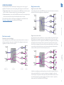
The AdderLink DV104T offers several ways of working in order to suit a range of
applications. Firstly there are two main operating modes: Single source and Dual source.
• Single source mode - In this mode, only one of the HDMI inputs is used at any time
and it is routed to all receivers using a choice of two switching options.
• Dual source mode - In this mode, both HDMI inputs are used concurrently and you
can determine exactly how they are shared between the four receivers.
The mode and the manner in which inputs are distributed are controlled from the
Transmitter configuration page of the AdderLink POD Manager.
Single source mode
Dual source mode
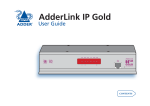
Single source mode > Auto
Auto is designed to provide redundancy to cover the possibility of input failure. The two
HDMI inputs can be derived from two ports of the same source or from two totally
independent sources. In this configuration, one HDMI input is designated as the primary
which will be fed to all receivers until such time that the transmitter detects a signal
failure. When that happens, all receivers will be automatically switched to the secondary
source until such time that the primary source becomes active again, whereupon, the
receivers will be re-joined to the recovered primary source.
^
HDMI Source
^
Transmitter
^
Receivers
CONFIGURATION
INSTALLATION
^
Screens
In addition to providing input redundancy, Auto mode is useful for situations where you
wish to automatically switch to a new source whenever it is plugged in or becomes
active. This aspect of operation would be particularly useful in situations where sources
are often being changed, e.g. temporary laptop connections to screens or projectors,
without the need to access AdderLink POD Manager.
INDEX
FURTHER
INFORMATION
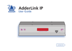
Dual source mode > Individual
In this configuration, the two HDMI inputs are shared between the four receivers in
whichever combination best suits the installation. The configuration remains static
regardless of the status of the source inputs.
Single source mode > Fixed
In this configuration, either of the HDMI inputs are routed to all receivers and remain so
until such time that the configuration is manually altered.
OPERATION
OPERATING MODES
3
CONFIGURATION
INSTALLATION
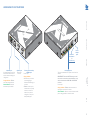
ADDERLINK DV104T FEATURES
Orange indicator - Flashes
when data is being transferred.
Green indicator - On when
the network port is enabled.
Options port
Reserved for
future use.
Primary and secondary
HDMI inputs
For each port:
Link output ports
These are the individual CATx outputs to each of the four
receivers.
Orange indicator
IMPORTANT:These are NOT Ethernet ports and
must not be connected to network switches or any
devices other than the ALDV100R or ALDV120R
receivers.
•On when the port is active
and routed (using the
AdderLink POD Manager) to
a receiver.
•Flashes to show the port
is active but is not currently
routed to a receiver. For
instance, if it is yet to be
configured or is set up as a
backup/standby input.
For each port:
OPERATION
Orange indicator - Flashes when the transmitter is
searching for the presence of a receiver.
Green indicator - On when a receiver is located and line
power is being provided to it via the link cable.
INDEX
Network port
A standard Ethernet port to link
the transmitter with a network
to allow remote monitoring and
configuration.
FURTHER
INFORMATION
Recessed
reset button
See
Troubleshooting
for details
Power
adapter
input
4
SUPPLIED ITEMS (ALDV104K KIT)
Information wallet
containing:
AdderLink DV100
(HDMI) receivers x 4
HDMI cable with locking
connectors 1.5m
Part number: VSCD12
FURTHER
INFORMATION
OPERATION
Four self-adhesive rubber feet
Quick start guide
Safety document
INDEX
AdderLink DV104T
transmitter unit
CONFIGURATION
INSTALLATION
Power adapter
(18W) and
country-specific
power cord
5
OPTIONAL EXTRAS
INSTALLATION
AdderLink DV120
(DVI-D) receiver
Part number: ALDV120R
CAT7 shielded foiled twisted pair
(S/FTP) network cable 50m
HDMI cable with locking
connectors 1.5m
Part number: VSCAT7-50
OPERATION
CONFIGURATION
Part number: VSCD12
Rack fascia plate
19” 3U rack mount chassis kit
Part number: ALDV-RMK-CHASSIS
INDEX
FURTHER
INFORMATION
Part number: ALDV-RMK-FASCIA
6
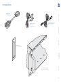
MOUNTING
There are three main mounting methods for the transmitter unit:
• The supplied four self-adhesive rubber feet,
• The rear mounting slot,
• Optional rack fascia plate (and rack mount chassis).
Rack fascia plate
The optional fascia plate (plus
screws), allows the transmitter to
be secured within a standard rack
chassis.
CONFIGURATION
Using the rear mounting slot
The slot at the rear of AdderLink DV104T unit allows it to be hung upon a fixed screw
that protrudes from the mounting surface.
5
)
19"
(0.
mm
FURTHER
INFORMATION
9.5
)
37"
(0.
OPERATION
mm
INSTALLATION
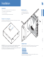
Installation
Installation involves linking the ALDV104T transmitter to the host computer; the
(up to) four receivers; a network port and the supplied power adapter.
• HDMI connections
• Network connection
• Receiver connections
• Power adapter connection
Connections may be made in any order however, where possible, connect the
transmitter to the mains supply as a final step.
INDEX
IMPORTANT: The internal circuit board is accessible through the mounting
slot. Ensure that any mounting screws protrudes no further than ½”
(12.5mm) into the module casing - serious electrical damage will be caused if
the screw makes contact with the internal circuitry.
CONNECTIONS
7
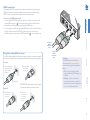
HDMI connections
The AdderLink DV104T transmitter has two input sockets that can be connected to
HDMI ports located on the same or different host computers, as required. A single
HDMI 1.5 meter connection lead is supplied with the transmitter unit.
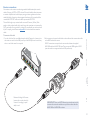
Using Adder locking HDMI connectors
The HDMI cables supplied by Adder feature a locking mechanism to prevent accidental
disconnections. Please follow the procedures below when inserting and removing them:
Insertion
2 Push the locking
pulled back (to show
green), insert the
connector.
collar forward
(to show red).
Locking collar
Removal
1 Pull the locking
collar back (to
show green).
IMPORTANT: Do not attempt to insert or remove
the connector while the red band is shown.
Indicators
The HDMI input ports each have an
adjacent recessed orange indicator to
provide useful configuration feedback, as
follows:
• On - The port is active and routed
(using the AdderLink POD Manager) to
a receiver.
• Flashing - The port is active but is
not currently routed to a receiver. For
instance, if it is yet to be configured or is
set up as a backup/standby input.
2 Gently pull
the connector
to disengage
it from the
socket.
INDEX
1 With the locking collar
Primary
HDMI
video/audio
input
FURTHER
INFORMATION
Secondary
HDMI
video/audio
input
OPERATION
CONFIGURATION
INSTALLATION
To connect the HDMI input port(s)
1 Use the supplied HDMI cable to link the output port of the host computer to the
primary HDMI input port (
) of the transmitter unit. See the section below for
details about the locking connectors used on Adder HDMI leads.
2 If a second link is required, use a high quality HDMI cable (of no more than 2 meters
in length - Adder part number:VSCD12) to join another port on the same (or
different) computer to the secondary HDMI input port (
) of the transmitter unit.
8
Network connection
The AdderLink DV104T transmitter contains a sophisticated browser-based
configuration, monitoring and management system. This system is made available through
a standard Ethernet connection to allow remote access and control of the transmitter
unit and its linked receivers.
OPERATION
FURTHER
INFORMATION
Connection to
standard network
switch
INDEX
For details about the management API, please see Appendix B.
CONFIGURATION
INSTALLATION
To connect the network port
1 Use a standard patch cable to link the Ethernet 10/100 network port (
) of the
transmitter unit to a nearby network switch.
For details about using the browser-based AdderLink POD Manager, please see the
section Accessing the AdderLink POD Manager.
9
Receiver connections
CONFIGURATION
2 At the remote end, connect the link cable to the module and then connect the module
to the HDMI socket of the screen.
If DVI-D connections are required at the remote end, substitute the supplied
ALDV100R modules for ALDV120R units. These convert the HDMI signals to DVI-D
(note that audio is not supported within the DVI specification). Maximum link length is 50 meters,
however, this must be reduced by
5 meters if a coupling (i.e. patch
cable) is used.
IMPORTANT:These are NOT Ethernet ports and must not be
connected to network switches or any devices other than the
ALDV100R or ALDV120R receivers.
INDEX
FURTHER
INFORMATION
OPERATION
To connect a link cable
1 For each of the four links, use shielded network cable of Category 6 or better to join
the receiver to one of the four LINK ports. Any of the LINK ports can be used in any
order or can be left vacant if not required.
INSTALLATION
Connections to the receivers are made using standard shielded twisted pair network
cables of Category 6 (S/STP or S/FTP) or better. The use of shielded cables is important
to maintain compliance with radio frequency energy emission regulations and ensure a
suitably high level of immunity to electromagnetic disturbances. For best results, Adder
recommends S/FTP CAT7 cable such as Adder part number VSCAT7-50.
The total link length to any receiver should not exceed 50 meters (160 feet). Patch
panels or cable couplers should only be used close to the transmitter unit, connected by
CAT7 patch cables of no more than 2m in length. The overall cable run must be reduced
by 5m if a coupling is used. Please see Appendix A for further details about extender
cables.
10
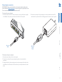
Power adapter connection
2 Connect the main body of the power adapter to a nearby earthed mains outlet. The
transmitter has no power switch so it will begin operation as soon as power is applied.
FURTHER
INFORMATION
To disconnect the power adapter
1 Isolate the power adapter from the mains supply.
2 Grasp the outer body of the power adapter plug where it connects with the
transmitter.
3 Gently pull the body of the outer plug away from the transmitter. As the body of the
plug slides back, it will release from the socket and you can fully withdraw the whole
plug.
Mains input
to power
adapter
INDEX
From power
adapter
OPERATION
CONFIGURATION
To connect the power adapter
1 Attach the output connector of the power adapter (country specific power supplies
are available) to the power input socket on the left side of the rear panel.
INSTALLATION
IMPORTANT: Please read and adhere to the electrical safety information
given within the Safety information section of this guide. In particular, do not
use an unearthed power socket or extension cable.
11
Configuration
INITIAL CONFIGURATION
Accessing the AdderLink POD Manager
To temporarily connect a computer to the network port
1 If you need to make a temporary connection for configuration purposes, use a
standard patch cable (cross-over or straight connections are both supported)
to link the Ethernet 10/100 network port (
) of the transmitter unit to your
computer’s network port.
Note: If the transmitter has been previously configured and those settings are unknown, see
the Troubleshooting section for details about reverting to the default settings.
INDEX
Temporary link from
your computer
FURTHER
INFORMATION
OPERATION
To access the AdderLink POD Manager
1 Use a computer that is directly or indirectly (i.e. via a network switch) connected to
the ALDV104T transmitter. If you need to make a temporary connection, see right Ü 2 Run a web browser on your computer and enter the IP address of the ALDV104T
transmitter. The default setting is: 192.168.1.22
3 If requested, enter your username and password to log on.
Note:The default username and password are ‘admin’ and ‘password’ respectively.
The opening page of the AdderLink POD Manager should be displayed:
CONFIGURATION
INSTALLATION
The configuration, monitoring and management of the ALDV104T transmitter and its
receivers is performed using the in-built AdderLink POD Manager (POD = Proof Of
Display) which is accessible via the network connection using a standard web browser.
Logging out
There is no log out option.You merely need to close the browser that you are using to
access the POD Manager.
12
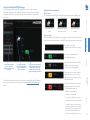
System Overview elements
HDMI Inputs
The line appearance and number colors indicate the status of the two HDMI inputs:
Both HDMI inputs
active.
One HDMI input active,
the other inactive.
Both HDMI inputs
inactive.
Remote outputs
The screen and line colors indicate the current status for each remote output.The number
within each screen shows which of the two HDMI inputs is being routed to that screen:
No receiver is attached.
(signified by short line and no screen).
INSTALLATION
The browser-based AdderLink POD Manager allows you to configure, monitor
and manage all aspects of the installation. The System Overview is the first page to
be displayed and provides a graphical overview of the installation as sensed by the
transmitter:
CONFIGURATION
Using the AdderLink POD Manager
The green screen and the blue
line leading to it indicate that
remote link 3 is operating
and the screen is correctly
registered with the transmitter.
Note: Status information about the inputs and outputs is also provided by the LED indicators
located next to each connector on the transmitter unit. See AdderLink DV104T features for
details.
The screen has been administratively
disabled, i.e. placed into standby
mode for power saving purposes.
Transmitter has lost contact with the
registered receiver (and its screen) the output status is unknown, e.g. link
cable disconnected.
There is an issue with the screen and
its registration with the transmitter.
The conditions detected are:
•
•
•
•
Monitor is not connected
Monitor is not powered
Incorrect i/p selected on monitor*
No active video on i/p to transmitter
* This feature is display screen dependent. It
works by detecting the loading on the HDMI
outputs from the receiver modules. However,
some screens load their HDMI lines even
when they are not displaying the video feed.
FURTHER
INFORMATION
The input lines shown
here indicate that HDMI
input 1 is active while
input 2 is inactive.
INDEX
Use the Rescan System
option to ensure the
displayed details are fully
up to date.
OPERATION
The screen is registered, active
and displaying an output.
13
The page includes the following:
• An Identify button that will cause the connected receiver to identify itself,
• The name of the attached screen (if present) as derived from the screen’s EDID,
• An Enable / Disable Screen option that allows you to administratively blank out (i.e.
send into standby mode) the attached screen,
• A Screen description field so that you may add suitably descriptive text, such as the
screen location - particularly useful in large distributed installations.
When you make any change, click the Save button.
INDEX
To identify receivers
When multiple receivers are located next to each other it can be difficult to single out
a particular unit. The Identify option within the configuration page for each receiver is
useful for this purpose.
1 Access the AdderLink POD Manager.
2 On the left side, click the Receiver Configuration button.
3 On the left side, click the required port number.
4 Click the Identify button. The orange and green indicators on the chosen receiver will
alternate for six seconds to provide visual identification.
FURTHER
INFORMATION
OPERATION
If there are any detected issues with the receiver or the
screen, information will be displayed within this page as well
as the System Overview page Ü
CONFIGURATION
Within the AdderLink POD Manager you can access the configuration page for any
receiver in either of two ways:
• Click the Receiver Configuration button and then click the required Port number
entry, or
• In the System Overview, click the appropriate screen image.
The configuration page will be displayed:
INSTALLATION
Receiver configuration
14
4 For Single source mode, now choose the required Input switching scheme:
• Fixed - to use one HDMI input to feed all four receivers regardless of the status of
that source.
• Auto - to use one HDMI input as an initial source and also provide automatic
switchover from that HDMI input to the other when either the initial source is lost
or the second source becomes active. The transmitter will switch back to the initial
source when either its status changes or the second source is removed.
5 Choose the required Source option(s). The remaining setting(s) on this page will
depend upon the choice you made in step 3 above.
• For Single source - choose the primary source: HDMI 1 or HDMI 2.
• For Dual source - choose the appropriate source for each output: HDMI 1 or
HDMI 2.
6 Click the Save button to apply your changes.
INSTALLATION
CONFIGURATION
OPERATION
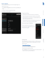
In this page you can:
• Determine the operation mode and how the various receivers and their screens are
allied with the HDMI input(s),
• Choose which screen configurations (EDID) are used to inform the HDMI source(s),
• Enable and disable all screens (such that they are sent into standby mode when
disabled).
To determine the operating mode
The operating mode, and the related input switching mode, are fundamental to
determining how the AdderLink DV104T links the HDMI inputs through to the remote
screens. For explanations of each mode, please see the section Operating modes.
1 Access the AdderLink POD Manager.
2 On the left side, click the Transmitter Configuration button (or click the
transmitter image within the System Overview).
3 Within the main section of the page, choose the required Operating Mode:
• Single source - to use a single HDMI input at a time, or
• Dual source - to use both HDMI inputs
simultaneously. When you change to the Dual
source setting, the other options will change
accordingly Ü
If you chose Dual source, jump to step 5. However,
if you chose Single source, you now need to
determine the Input switching scheme.
FURTHER
INFORMATION
Within the AdderLink POD Manager you can access the Transmitter configuration page
in either of two ways:
• Click the Transmitter Configuration button, or
• In the System Overview, click the transmitter image.
The configuration page will be displayed:
continued
INDEX
Transmitter configuration
15
1 Access the AdderLink POD Manager.
2 On the left side, click the Transmitter Configuration button (or click the
transmitter image within the System Overview).
3 Click the Show EDID port 1 or
Show EDID port 2 option. The EDID
information for the chosen port will be
shown Ü
INSTALLATION
CONFIGURATION
To view EDID source port details
Useful for troubleshooting purposes, you can view various details related to the EDID
information that is being presented to the video source(s) linked to the transmitter’s
HDMI input(s). This includes the source mode being used (Default, Cloned or Transparent),
the preferred resolution and pixel clock values as well as the whole raw hex data that is
being presented.
OPERATION
1 Access the AdderLink POD Manager.
2 On the left side, click the Transmitter Configuration button (or click the
transmitter image within the System Overview).
3 Click the Disable all Screens button or the Enable all Screens button, as
appropriate.
FURTHER
INFORMATION
To enable and disable all screens
This option allows you to easily send all connected screens into standby mode and
similarly bring them all back to full operation at the click of a button. When the Disable
all Screens command is sent, each receiver removes its video signal which causes the
connected screen to enter power saving standby mode.
When you disable any screens, their corresponding graphical
representation within the System Overview page will be
shown in black until they are re-enabled Ü
INDEX
To choose the screen configurations used to inform the HDMI sources
Before an HDMI source can provide video output it needs to be informed about the
capabilities and requirements of the attached screens. The AdderLink POD Manager lets
you choose from three different EDID (Extended Display Identification Data) sources:
• Default - A standard EDID retained by the transmitter will be used.
• Cloned and Transparent - Both of these options will copy and use the EDID
information from the display screen that is selected in the adjacent Screen field,
once you click the Save button. The entries available within the Screen field
will depend upon which screens are attached to the receivers at the time. The
difference between the Cloned and Transparent modes is that a Cloned EDID will
continue to be used, even if the screen from which it was copied is replaced with a
different type. Whereas in Transparent mode, the EDID of the replacement screen
will automatically be taken and used in place of the original.
1 Access the AdderLink POD Manager.
2 On the left side, click the Transmitter Configuration button (or click the
transmitter image within the System Overview).
3 Within the main section of the page, choose the most appropriate EDID mode for the
required HDMI input entry: EDID Port 1 source or EDID Port 2 source:
• Default - to use an internally-held general purpose EDID.
• Cloned - to copy and use the EDID of the current Screen entry, such that it will
persist even if that screen is replaced.
• Transparent - to copy and use the EDID of the current Screen entry, such that it
will automatically change if that screen is replaced.
4 Adjacent to the HDMI Input entry (EDID Port 1 source or EDID Port 2 source), select
the Screen name if required.
5 Click the Save button to copy and apply the chosen EDID to the HDMI input port.
16
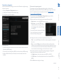
System configuration
To configure access details for the network port
1 Access the AdderLink POD Manager.
2 On the left side, click the System Configuration button.
3 Click the Network Settings button. The following page will be displayed:
FURTHER
INFORMATION
4 If required, change the setting of the Use DHCP option. When set to Enabled, the
transmitter unit will attempt to contact a local DHCP (Dynamic Host Configuration
Protocol) server in order to automatically gain all of the necessary network settings.
When enabled, no other network settings are required and the other network options
will all become non-editable and you can skip to step 6.
Note:When you use the DHCP option, the IP address for the transmitter will be set by the
DHCP server and the transmitter will move to that address.To discover the IP address it will
be necessary to view DHCP server logs or interrogate the DHCP server. It may be possible
to configure the DHCP server to use a particular address for the transmitter. If you cannot
connect to the transmitter after switching to DHCP mode, see the Troubleshooting section for
recovery details.
5 If the Use DHCP option is set to Disabled, you need ensure that the remaining network
options are appropriate for your installation. Change the System IP Address and System
Netmask options if required. If access from beyond the local network is required,
ensure that the System IP Gateway entry matches that of your local network gateway.
Note:When you change the System IP Address and click Save, the transmitter will move to
that new address and you will need to access it again at the new address. If Logon security is
enabled, you will be prompted afresh for your username and password.
6 When all settings are complete, click the Save button to apply your changes.
INDEX
In this page you can:
• Configure access details for the network port,
• Manage authorized users and their access passwords,
• Check and upgrade the firmware contained within the transmitter and/or any receiver
units connected to it.
OPERATION
CONFIGURATION
INSTALLATION
Within the AdderLink POD Manager click the System Configuration button to display
the System configuration page:
17
INSTALLATION
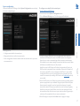
To check and upgrade firmware
1 Download the latest upgrade file from the Adder Technology website (www.adder.com):
View the Technical Support > Updates section.
2 Access the AdderLink POD Manager.
3 On the left side, click the System Configuration button.
4 Click the Firmware Upgrade option. The transmitter will scan all ports to
determine the firmware versions of all connected receivers. The results are then
shown within the Upgrade page together with the firmware version of the transmitter:
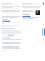
5 Enter/edit the required Username and Password.
• Usernames and passwords can consist of up to sixteen alphanumeric characters.
• Passwords can also include keyboard symbols.
• Usernames and passwords are case sensitive.
6 Click the Save button to apply your changes and return to the previous page.
Note: If you edit the username and/or password of the account with which you are currently
logged on, when you next attempt to change pages you will be logged off and prompted for
your username and password.
By default, only the transmitter option will be ticked. If necessary, change this to
determine which devices should be included within the upgrade process.
5 Click the Continue button. However, if you wish to abort the upgrade process at this
point, click the Reboot button.
6 Click the Upload button to display a file dialog.
7 Use the file dialog to locate the upgrade file that you downloaded earlier and click
OK.
Note: If you select a file which is not an upgrade file, an upgrade failure message will be
displayed. Click the Reboot button before attempting another upgrade.
If the file is correct, the upgrade process will commence to all devices that are ticked
within the list. The POD Manager page will indicate that uploading is in progress; also
the orange indicators on the transmitter’s output ports will cease flashing for the
duration.
8 When the upgrade process is complete, click the Reboot button to take the
transmitter and the receivers through a cold restart cycle.
INDEX
4 To add or edit a user, select one of the six user
locations and then click the Edit User button
to display the following options Ü
FURTHER
INFORMATION
OPERATION
CONFIGURATION
To manage authorized users and their passwords
1 Access the AdderLink POD Manager.
2 On the left side, click the System Configuration button.
3 Click the User Accounts option. The following page will be displayed:
18
Operation
INSTALLATION
In operation, most AdderLink DV installations require no intervention once configured.
The transmitter unit takes care of all connection control behind the scenes and
AdderLink POD Manager provides suitable management tools for remote monitoring.
MANAGING THE INSTALLATION
The AdderLink POD Manager provides a clear and intuitive overview of the installation
that allows you to take swift action if necessary.
Use the Rescan System
option to ensure the
displayed details are
fully up to date.
For explanations of the various line
and screen colors, please see the
section System overview elements.
OPERATION
FURTHER
INFORMATION
Within the AdderLink POD Manager you can:
• View the real-time overview of the installation. See the section System overview
elements for explanations of the various line and screen colors.
• Ensure that the graphical view of installation is fully updated.
See Rescanning the System Overview.
• React to an input source failure and switch to the alternative input if available.
See the section Changing to an alternative input source.
• Enable and disable all screens (such that they are sent into standby mode when disabled).
See the section Enabling and disabling all screens.
• Make alterations to key transmitter or receiver settings.
• Administer network settings, user accounts and firmware upgrades.
INDEX
The System Overview page of the AdderLink POD Manager should be shown:
CONFIGURATION
To display the System Overview page within AdderLink POD Manager
1 Use a computer that is directly or indirectly (i.e. via a network switch) connected
to the ALDV104T transmitter. If you need to make a temporary connection, see the
section Accessing the AdderLink POD Manager. 2 Run a web browser on your computer and enter the IP address of the ALDV104T
transmitter. The default setting is: 192.168.1.22
19
To rescan the network
1 Access the AdderLink POD Manager.
2 If the System Overview is not already showing (see left), click the System Overview
button.
3 Click the Rescan System option to ensure that the register of devices and the
displayed System Overview are fully up to date.
Enabling and disabling all screens
This option allows you to easily send all connected screens into standby mode and
similarly bring them all back to full operation at the click of a button. When the Disable
all Screens command is sent, each receiver removes its video signal which causes the
connected screen to enter power saving standby mode.
When you disable any screens, their corresponding
graphical representation within the System Overview page
will be shown in black until they are re-enabled Ü
To enable and disable all screens
1 Access the AdderLink POD Manager.
2 On the left side, click the Transmitter Configuration button (or click the
transmitter image within the System Overview).
3 Click the Disable all Screens button or the Enable all Screens button, as
appropriate.
INSTALLATION
During power up, the transmitter will scan the network of connected receivers to
determine their layout and harvest their EDID information. The details gleaned are also
used to populate the System Overview shown left.
All AdderLink DV receivers have unique IDs that are registered with the transmitter. If
a receiver is subsequently removed and replaced, the replacement receiver will begin
working immediately with the transmitter. However, the new receiver will remain
represented within the System Overview page as an orange screen with red line as
shown left. This is because the new receiver is not fully registered with the transmitter.
Additionally, receivers that have been permanently removed will remain shown as orange
screen entries as they are still registered. Use the Rescan System option to refresh the
transmitter’s register of devices and the subsequent System Overview.
CONFIGURATION
Rescanning the System Overview
FURTHER
INFORMATION
INDEX
To change to an alternative input source
1 Access the AdderLink POD Manager.
2 If the System Overview is not already showing (see left), click the System Overview
button.
3 Click the Switch to input x option, where x is the alternative input source to the
one currently being used. The transmitter will immediately switch to the requested
input source.
Note:When you use the Switch to port x option, the transmitter will change to Single
source mode and will switch all outputs to the chosen source port.The transmitter will
not check whether a valid video feed is available on the intended HDMI input.Within the
System Overview, if the intended input source is shown in red, then no valid signal is currently
available.
OPERATION
Changing to an alternative input source
Should circumstances dictate, within the AdderLink POD Manager you can take
immediate control and switch all receivers from one source to the other. This might be
necessary if the primary source becomes unavailable and the transmitter is connected to
a viable secondary source. It is also possible to make this occur automatically using the
Single source > Auto setup. See Transmitter configuration for details.
20
Further information
• Technical support – www.adder.com/contact-support-form
For technical support, use the contact form in the Support section of the
adder.com website - your regional office will then get in contact with you.
CONFIGURATION
• Adder Forum – forum.adder.com
Use our forum to access FAQs and discussions.
OPERATION
• Online solutions and updates – www.adder.com/support
Check the Support section of the adder.com website for the latest solutions and
firmware updates.
FURTHER
INFORMATION
If you are still experiencing problems after checking the information contained within this
guide, then we provide a number of other solutions:
INSTALLATION
GETTING ASSISTANCE
INDEX
This chapter contains a variety of information, including the following:
• Getting assistance - see right
• Troubleshooting
• Appendix A - Network cables for use with digital extenders
• Appendix B - Management API specification
• Safety information
• Warranty
• Radio frequency energy statements
21
CONFIGURATION
Problem: A screen has been replaced with a different model, however, the
replacement is not showing the video output correctly.
It is possible that the EDID (Extended Display Identification Data) information being
used by the source device is incompatible with the replacement screen. The transmitter
has several methods for dealing with EDID information. For further details, please see
the section To choose the screen configurations used to inform the HDMI sources.
Remedy:
Try changing the EDID port x option to Transparent in order to force the transmitter to
read the EDID information from the new screen.
To restore default settings, use a
straightened out paperclip to press
and hold the recessed reset button
while power is applied.
After reset, the following default settings will be restored:
• Username:
admin
• Password:
password
• IP address:
192.168.1.22
• Netmask: 255.255.255.0
• Gateway:
192.168.1.0
IMPORTANT:You are strongly recommended to set a new username and password as
soon as possible. See the section To manage authorized users and their passwords for
details.
OPERATION
Remedy:
Within the System Overview page, click the Rescan System option.
FURTHER
INFORMATION
Problem: A receiver has been replaced, however, its orange screen representation within the System Overview page remains shown.
Each receiver has a unique identity code. Even though the replacement receiver is
working correctly, it is not the one that is registered with the transmitter. For further
details, please see the section Rescanning the System Overview.
Problem:The transmitter is inaccessible because the username and/or
password have been forgotten or the IP address is unknown.
Remedy:
You need to reset the transmitter back to its default settings.
1 Remove power from the transmitter.
2 Use a narrow implement, such as a straightened out paperclip, to push and hold the
recessed reset button, located near to the power connector,
3 Re-apply power to the transmitter and then release the reset button.
INDEX
Problem: While attempting a firmware upgrade, the web browser reports
that there is ‘no data’ or a similar message.
This error is caused by cached data error as a result of a previously failed upgrade attempt. It is necessary to clear the browser’s cache.
Remedy:
Using the browser settings, clear its internal cache - or alternatively restart the browser.
INSTALLATION
TROUBLESHOOTING
22
APPENDIX A - Cables for use with digital extenders
Insulation displacement
The teeth of the insulation displacement connectors are designed to straddle and hug
the sides of the solid center conductor of the cable.
The teeth of the insulation piercing connectors penetrate the middle of the cable and
nest in between the stranded wires. If insulation piercing connectors are used on solid
core cable then the connection will not be stable as the teeth will try to but are unable
to penetrate the solid center conductor. The teeth will then slide off the solid core and
not make a stable contact.
Types of shielding
Solid
Stranded
Stranded cabling is found in patch cables and is intended to connect the front of the wall
plate to the extender or computer using RJ45 connectors. They need to be more flexible
because the cabling gets disconnected and connected constantly.
For a digital extender application, solid conductor cables give a better performance as
these allow for a higher bandwidth and have less attenuation. Ideally a thickness of 22
AWG should be used.
Insulation piercing
The third and final factor in determining the cable to be used in digital extension is
shielding. The shielding protects the cable from two types of interference, internal
crosstalk and external interference. Internal crosstalk is the interference between the
different pairs inside the cable. External interference is any interference that comes from
outside the cable. This is caused by many things; proximity to mobile phones, bundling
cables together or running them over lighting fixtures.
Internal crosstalk is most detrimental to digital extension as the signals cannot be
recovered after experiencing crosstalk.You are left with a black screen.
The most common type of shielding is Screened/Unshielded Twisted Pair (S/UTP). This has
an overall shield and will protect the signal from external interference. However it does
not provide any protection from crosstalk.
The next type of shielding is Shielded Twisted Pair (STP). This has four individual shields,
one for each data pair. This is good for protecting the signal from internal crosstalk but
does not provide an overall shield to protect against external interference.
If you combine the two types of shielding together you have Screened/Shielded Twisted Pair
(S/STP). This is also sometimes referred to as Shielded/Foil Twisted Pair (S/FTP). This has four
individual shields, one for each pair and an overall shield. S/STP is the best cable to protect
against any interference and is the cable choice to be used for digital KVM extension.
INSTALLATION
CONFIGURATION
Twisted pair cables can have either solid or stranded conductors. Solid cables come
in bulk spools and are often referred to as infrastructure or bulk cabling. They are less
flexible than stranded cables but have less attenuation. These cables are typically run
throughout a building and terminate at the rear of a wall plate.
For each type of cable there is also an associated RJ45 connector. It is important that the
correct type of connector is used for the type of cabling.
Insulation displacement RJ45 connectors are designed to work with solid conductor cables
while insulation piercing RJ45 connectors are designed to work with stranded conductor
cables.
OPERATION
Types of cable
Types of RJ45 connector
FURTHER
INFORMATION
The demands of extending high resolution DVI and HDMI digital video signals are
considerable and mean that it is not possible to use Cat5e cabling to achieve the
maximum extension distance of 50 meters. The large video bandwidth involved means
that to achieve the best possible performance from digital extenders, it is vital that the
correct cabling is chosen.
There are three important factors to consider when choosing a cable for use with digital
extenders.
IMPORTANT: Please remember that even though they use network-style
cables, the link ports of the modules are NOT Ethernet ports and must not
be connected to network switches or any other devices.
INDEX
Introduction
23
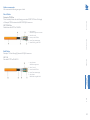
Adder recommends
We recommend the following two types of cable:
Daetwyler 7702P flex
This is stocked by Adder with the following part number VSCAT7-50. This is a 50m length
of Daetwyler 7702P terminated with HRS TM31P RJ45 connectors.
CU 7702 4P flex
Flexible data cable S/FTP Cat.7 AWG26
INSTALLATION
Patch Cables
1 Inner conductor:
AWG26 bare copper wire, stranded
3 Screen pair: Alu PETP foil
4 Screen: Tinned braided copper
5 Sheath: FR/PVC grey RAL 7035
Bulk Cables
CONFIGURATION
2 Wire: 0.99 mm Ø
CU 7120
Data cable S/FTP Cat.7A AWG 23
1 Inner Conductor:
AWG23 bare copper wire
2 Wire: 1.5 mm Ø
OPERATION
Daetwyler 7120 with Harting RJ Industrial 10G RJ45 connectors.
3 Screen Pair: Alu PETP foil
INDEX
5 Outer Sheath:
FRNC/LSOH orange RAL 2003
FURTHER
INFORMATION
4 Screen: Tinned braided copper
24
APPENDIX B - Management API specification
The following aspects of the ALDV104T and the connected ALDV100s can be controlled:
• HDMI input routed to all ALDV100s,
• Automatic input switching mode,
• Enable/disable of all connected screens,
• Enable/disable of individual screens,
• Source of the EDID presented at each HDMI input.
GET /cgi-bin/api?<params> HTTP/1.1
Where <params> is one or more URI parameters to describe the operation to be performed.
The response is an HTTP response. The first line contains the status code indicating the
success or failure of the operation.
The response is either:
HTTP/1.1 200 OK
or an HTTP error response:
HTTP/1.1 400 Bad Request
Command and Control Operations
INSTALLATION
All operations of the API are performed using a URI contained in an HTTP request. The
control and configuration operations are performed by the following request:
CONFIGURATION
The API allows monitoring of the following:
• Status of the ALDV104T unit,
• Status of the two HDMI inputs to the ALDV104T,
• Topology of the connections to ALDV100R units,
• Status of up to four ALDV100R units connected to the ALDV104T,
• Status of the screens connected to the ALDV100R units,
• Status of the connections between the ALDV104T and the ALDV100s.
Message Structure
The following command and control operations are available:
Switch to input
Select Input 1
Switch all outputs to the signal on HDMI input 1
GET /cgi-bin/api?opmode=0&insrc=1 HTTP/1.1
Select input 2
Switch all outputs to the signal on HDMI input 2
OPERATION
API Overview
API Operation
GET /cgi-bin/api?opmode=0&insrc=2 HTTP/1.1
Set input switching mode
Set fixed mode
Set the input switching mode to fixed. The selected input signal will be routed to the
outputs regardless of the status on the input signals on inputs 1 and 2. The opmode is set
to 0 to switch to single source mode at the same time.
FURTHER
INFORMATION
The AdderLink DV104T is monitored and managed by a web interface. This provides
topology and status information and allows configuration of the transmitter unit plus the
receiver units connected to it.
The unit also has a management API via the same HTTP interface. This allows the
status, topology and configuration to be managed from another application, via HTTP
commands. Only the first line of the HTTP method is required as the URI contains all
the required information to perform the requested operation.
GET /cgi-bin/api?opmode=0&swmode=0 HTTP/1.1
Set auto mode
Set the input switching mode to auto. In this mode the selected input source will
automatically switch when an input source becomes active, either by it being plugged in
or by the source becoming active (e.g. the player being powered on). If the active source
becomes inactive then it switches to the other input as long as it is active. This provides a
fallback to a backup source if the primary input fails. The opmode is set to 0 to switch to
single source mode at the same time.
GET /cgi-bin/api?opmode=0&swmode=1 HTTP/1.1
INDEX
Introduction
25
GET /cgi-bin/api?emod1=0 HTTP/1.1
Disable individual screen
Disable an individual screen so it does not display a picture (most screens will go into
standby mode). The screen is identified by the port number (1..4) of the ALDV104T to
which it is attached. This is intended to blank all screens when not in use, overnight etc.
GET /cgi-bin/api?port=1?screen1=0 HTTP/1.1
GET /cgi-bin/api?port=2?screen1=0 HTTP/1.1
GET /cgi-bin/api?port=3?screen1=0 HTTP/1.1
GET /cgi-bin/api?port=4?screen1=0 HTTP/1.1
Enable screen
Enables an individual screen so it displays a picture. This is the opposite of disable
screen command and is used to restore the display which was previously disabled. This
command will enable a screen , regardless of whether it was disabled by the disable all
screens command or disable individual screen command.
GET /cgi-bin/api?port=1?screen1=1 HTTP/1.1
GET /cgi-bin/api?port=2?screen1=1 HTTP/1.1
GET /cgi-bin/api?port=3?screen1=1 HTTP/1.1
GET /cgi-bin/api?port=4?screen1=1 HTTP/1.1
Set source for EDID for input
The EDID presented on each input is either the default one built in to the ALDV104T or
is obtained from one of the screens connected to a connected ALDV100R. The source of
the EDID for each of inputs 1 and 2 is controlled individually. There are three options
• Default – built in EDID,
• Clone from display – copy EDID from selected display and always use this EDID,
• Transparent from display – copy EDID from selected display and re-read from display
every time the display is re-connected. This allows the EDID to change dynamically if a
different display is connected.
Clone from display
Copy the EDID from the selected display and always use it for this input. The esrc1
parameter is used when controlling the EDID for input 1, esrc2 controls input 2. The
value of the esrc parameter is the port number (1..4) on the ALDV104T through which
the selected display is connected. To select this mode emod1/emod2 = 1.
GET /cgi-bin/api?emod1=1&esrc1=1 HTTP/1.1
GET /cgi-bin/api?emod2=1&esrc2=1 HTTP/1.1
This example shows the EDID obtained from the display on port 1. Similarly esrc1/2 =
2,3 or 4 to select the screen connected to ports 2,3 or 4
Transparent from display
Copy the EDID from the selected display and re read it whenever the display becomes
active. This allows the EDID to change dynamically if a different display is connected to
the selected port. The esrc1 parameter is used when controlling the EDID for input 1,
esrc2 controls input 2. The value of the esrc1/esrc2 parameter is the port number (1..4)
on the ALDV104T through which the selected display is connected. To select this mode
emod1/emod2 = 2.
GET /cgi-bin/api?emod1=2&esrc1=1 HTTP/1.1
GET /cgi-bin/api?emod2=2&esrc2=1 HTTP/1.1
This example shows the EDID obtained from the display on port 1. Similarly esrc1/2 =
2,3 or 4 to select the screen connected to ports 2,3 or 4
FURTHER
INFORMATION
GET /cgi-bin/api?screen1=1 HTTP/1.1
GET /cgi-bin/api?emod2=0 HTTP/1.1
INDEX
Enable all screens
Enables all screens so they display a picture. This is the opposite of disable all screens and
is used to restore the display which was previously disabled. This command will enable all
screens, regardless of whether they were disabled by the disable all screens command or
disable individual screen command.
INSTALLATION
GET /cgi-bin/api?screen1=0 HTTP/1.1
CONFIGURATION
Set to Default EDID
Use the built in default EDID for the input. The emod1 parameter controls input 1, emod2
controls input 2.
To select this mode emod1/emod2 = 0.
OPERATION
Screen Enable/Disable
Disable all screens
Disables all screens so they do not display a picture (most screens will go into standby
mode). This is intended to blank all screens when not in use, overnight etc.
26
Status Operation
{“ad”:”b”,”ln”:”ir”},
{“ad”:”1”,”ln”:”hl”,”rx”:”nr”,”sw”:”1”,”flt”:””},
{“ad”:”2”,”ln”:”hl”,”rx”:”nr”,”sw”:”1”,”flt”:”HEDS”,“nd”:
”DELL<br>Descriptive text”},
{“ad”:”3”,”ln”:”hr”,”rx”:”nr”,”sw”:”1”,”flt”:””},
{“ad”:”4”,”ln”:”hs”}
]
There are 6 objects of 2 types, and object is identified by the value of its “ad” attribute.
Input type
The first two objects represent the 2 HDMI inputs. Each object has two attributes “ad”
and “ln”:
“ad” : “a|b” identifies the port a = input 1 b = input 2
“ln” : “ir”
input is red (disconnected / bad)
“ln” : “ig”
input is good (connected / good)
INSTALLATION
“1|2|3|4” identifies the port 1 = output 1 .. 4 = output 4
“hs” output is not in use
“hl” output is connected
“hr” output is not connected
“rx” : “nr” screen is not displaying signal
“rx” : “ng” screen is displaying signal
“rx” : “na” screen is in unknown state cannot be contacted (orange on display)
“rx” : “nb” screen is in disabled state (black on display)
“sw” : “1” screen is switched to input 1 (may or may not be displaying image, see “rx”)
“sw” : “2” screen is switched to input 2 (may or may not be displaying image, see “rx”)
“flt” : “H” Hot Plug not detected from display
“flt” : “E” EDID not successfully read from display
“flt” : “D” Display not selected this input source
“flt” : “S” Signal not detected at output to display
“nd” : “Name<br>Description” Name of screen and descriptive text stored in receiver.
CONFIGURATION
{“ad”:”a”,”ln”:”ir”},
:
:
:
:
OPERATION
[
“ad”
“ln”
“ln”
“ln”
continued
FURTHER
INFORMATION
GET /status/tree HTTP/1.1
The response is an HTTP response containing a status code followed by headers and a
body containing a JSON encoded array of object.
A typical example of a response is:
Output type
The remaining 4 objects represent the 4 output ports and the ALDV100Rs and displays
connected to them. Each object has 2 attributes “ad” and “ln”, plus four optional
attributes “rx”, “sw”, “flt” and “nd”.
INDEX
Get status
The operation to get the status fetches all the information about the topology and status
of the ALDV104T, its inputs, connections to ALV100R units, their status and that of the
attached screens.
The request to get the status is:
27
{“ad”:”1”,”ln”:”hl”,”rx”:”nr”,”sw”:”1”,”flt”:”S”},
- connected to input 1 not displaying signal. No signal detected. Input on ALDV104T not
connected.
{“ad”:”1”,”ln”:”hl”,”rx”:”nr”,”sw”:”1”,”flt”:”D”},
- connected to input 1 not displaying signal. Display not detected. Input source on display
not selected.
{“ad”:”1”,”ln”:”hl”,”rx”:”nr”,”sw”:”1”,”flt”:”HEDS”,”nd”:”Del
l<br>Description of screen”},
- connected to input 1 not displaying signal. No Hotplug, EDID, signal or display detected.
Cable unplugged. Screen name is “Dell” and the descriptive text is “Description of
screen”.
{“ad”:”1”,”ln”:”hl”,”rx”:”nb”,”sw”:”1”},
- connected to input 1 not displaying signal as disabled
INSTALLATION
{“ad”:”1”,”ln”:”hl”,”rx”:”nr”,”sw”:”1”,”flt”:”HEDS”},
- connected to input 1 not displaying signal. No Hotplug, EDID, signal or display detected.
Cable unplugged.
The ALDV104T implementation has security on its web interface, using HTTP Digest
Authentication (RFC 2617). This is enabled by default and can be disabled via the web
interface.
If security is enabled, the API needs to provide an Authorization header in requests,
otherwise the operations will fail and return a 401 Unauthorized error.
Digest authentication uses a challenge response model. A request sent without an
Authorization header will receive a 401 response with a WWW-Authenticate header.
The parameters are extracted from this and used along with the username, password
and request URI to generate the response placed in the Authorization header of the API
requests.
The status operation can be performed without the need for authentication, only the
commands sent to /cgi-bin/api need authentication.
CONFIGURATION
{“ad”:”1”,”ln”:”hl”,”rx”:”ng”,”sw”:”1”,“flt”:”’},
- connected to input 1 - all good.
Security
OPERATION
Output type (continued)
Typical outputs are:
{“ad”:”1”,”ln”:”hs”}, - not in use
INDEX
Similarly for outputs 2,3,4.
FURTHER
INFORMATION
{“ad”:”1”,”ln”:”hr”,”rx”:”na”,”sw”:”1”},
- not connected to input 1 not displaying signal
28
INSTALLATION
Adder Technology Ltd warrants that this product shall be free from defects in
workmanship and materials for a period of two years from the date of original purchase.
If the product should fail to operate correctly in normal use during the warranty period,
Adder will replace or repair it free of charge. No liability can be accepted for damage due
to misuse or circumstances outside Adder’s control. Also Adder will not be responsible
for any loss, damage or injury arising directly or indirectly from the use of this product.
Adder’s total liability under the terms of this warranty shall in all circumstances be
limited to the replacement value of this product.
If any difficulty is experienced in the installation or use of this product that you are
unable to resolve, please contact your supplier.
CONFIGURATION
•
•
•
WARRANTY
OPERATION
•
For use in dry, oil free indoor environments only.
Warning - live parts contained within power adapter.
No user serviceable parts within power adapter - do not dismantle.
Plug the power adapter into a socket outlet close to the module that it is powering.
Do not use an unearthed power socket or extension cable.
Replace the power adapter with a manufacturer approved type only.
Do not use the power adapter if the power adapter case becomes damaged, cracked
or broken or if you suspect that it is not operating properly.
If you use a power extension cord with the units, make sure the total ampere rating of
the devices plugged into the extension cord does not exceed the cord’s ampere rating.
Also, make sure that the total ampere rating of all the devices plugged into the wall
outlet does not exceed the wall outlet’s ampere rating.
Do not attempt to service the units yourself.
Do not use to link between buildings.
The four CATx ‘LINK’ interfaces (RJ45 style connectors) of the transmitter must only
be connected to AdderLink DV receivers. Do not connect these interfaces to any
other devices, particularly network or telecommunications equipment.
FURTHER
INFORMATION
•
•
•
•
•
•
•
INDEX
SAFETY INFORMATION
29
FCC Compliance Statement (United States)
This equipment generates, uses and can radiate radio frequency energy and if not
installed and used properly, that is, in strict accordance with the manufacturer’s
instructions, may cause interference to radio communication. It has been tested and
found to comply with the limits for a class A computing device in accordance with
the specifications in Subpart J of part 15 of FCC rules, which are designed to provide
reasonable protection against such interference when the equipment is operated in a
commercial environment. Operation of this equipment in a residential area may cause
interference, in which case the user at his own expense will be required to take whatever
measures may be necessary to correct the interference. Changes or modifications not
expressly approved by the manufacturer could void the user’s authority to operate the
equipment.
CONFIGURATION
This equipment has been tested and found to comply with the limits for a class A
computing device in accordance with the specifications in the European standard
EN55022. These limits are designed to provide reasonable protection against harmful
interference. This equipment generates, uses and can radiate radio frequency energy
and if not installed and used in accordance with the instructions may cause harmful
interference to radio or television reception. However, there is no guarantee that
harmful interference will not occur in a particular installation. If this equipment does
cause interference to radio or television reception, which can be determined by turning
the equipment on and off, the user is encouraged to correct the interference with one
or more of the following measures: (a) Reorient or relocate the receiving antenna.
(b) Increase the separation between the equipment and the receiver. (c) Connect
the equipment to an outlet on a circuit different from that to which the receiver is
connected. (d) Consult the supplier or an experienced radio/TV technician for help.
OPERATION
European EMC directive 2004/108/EC
FURTHER
INFORMATION
A Category 5 (or better) twisted pair cable must be used to connect the units in order
to maintain compliance with radio frequency energy emission regulations and ensure a
suitably high level of immunity to electromagnetic disturbances.
All other interface cables used with this equipment must be shielded in order to maintain
compliance with radio frequency energy emission regulations and ensure a suitably high
level of immunity to electromagnetic disturbances.
INSTALLATION
RADIO FREQUENCY ENERGY
This equipment does not exceed the class A limits for radio noise emissions from digital
apparatus set out in the radio interference regulations of the Canadian Department of
Communications.
Le présent appareil numérique n’émet pas de bruits radioélectriques dépassant les limites
applicables aux appareils numériques de la classe A prescrites dans le règlement sur le
brouillage radioélectriques publié par le ministère des Communications du Canada.
INDEX
Canadian Department of Communications RFI statement
30
INSTALLATION
www.adder.com/contact-details
Support:
forum.adder.com
CONFIGURATION
Contact:
OPERATION
www.adder.com
INDEX
FURTHER
INFORMATION
Web:
Documentation by:
www.ctxd.com
© 2014 Adder Technology Limited
All trademarks are acknowledged.
Part No. MAN-ALDV104T-ADDER • Release 1.0c
31
D
Default
EDID 16
resetting 22
DHCP 17
Disable all Screens 16
Dual source 15
Dual source mode 3
DV100R 2,10
DV120R 2,10
I
Input source
alternative 20
L
Link output ports 4
Logon Security 17
M
Managing 19
O
Options port 4
P
POD Manager
accessing 12
Power adapter
connection 11
input 4
R
Rack fascia plate 6,7
Rack mounting 7
Rear mounting slot 7
Receiver configuration 14
Receiver connections 10
Rescan
network 20
Resetting defaults 22
RJ45 connector 23
T
Transmitter configuration 15
Transparent
EDID 16
Troubleshooting 22
U
Upgrade 18
User
settings 18
W
Warranty 29
CONFIGURATION
H
HDMI
connections 8
indicators 8
inputs 4
S
Safety information 29
Screened/Unshielded Twisted
Pair 23
Shielded Twisted Pair 23
Single source 15
Single source mode 3
Slot
rear mounting 7
Solid cables 23
S/STP 23
STP 23
Stranded cabling 23
S/UTP 23
OPERATION
C
Cable 23
Cloned
EDID 16
Connections
overview 7
transmitter - power in 11
F
Fixed
mode 3,15
N
Network
cable 23
connection 9
port 4
rescan 20
settings 17
Network port
temporary connection 12
FURTHER
INFORMATION
B
Bracket
rack mount 7
Brackets
fitting 7
E
EDID 16
Edit User 18
Enable all Screens 16
Error symbols 13
INDEX
A
API specification 25
Auto
mode 3,15
INSTALLATION
Index
32