1
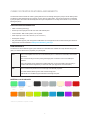
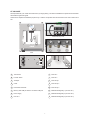
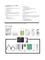
CubeX
TM
3D printer
User guide
See inside for use and safety information.
INTRODUCTION
Copyright . . . . . . . . . . . . . . . . . . . . . . . . . . . . . . . . . . . . . . . . . . . . . . . . . . . . . . . . . . . . . . . . . . . . . . . . . . . . . . . . . . . . . . . . . . . . . . . . . . . . . . . . . . . . . . . 3
FCC notice . . . . . . . . . . . . . . . . . . . . . . . . . . . . . . . . . . . . . . . . . . . . . . . . . . . . . . . . . . . . . . . . . . . . . . . . . . . . . . . . . . . . . . . . . . . . . . . . . . . . . . . . . . . . . . 3
Warranty . . . . . . . . . . . . . . . . . . . . . . . . . . . . . . . . . . . . . . . . . . . . . . . . . . . . . . . . . . . . . . . . . . . . . . . . . . . . . . . . . . . . . . . . . . . . . . . . . . . . . . . . . . . . . . . 3
Limitation of liability . . . . . . . . . . . . . . . . . . . . . . . . . . . . . . . . . . . . . . . . . . . . . . . . . . . . . . . . . . . . . . . . . . . . . . . . . . . . . . . . . . . . . . . . . . . . . . . . . . . . . . . 3
IMPORTANT SAFETY INFORMATION
Safety symbols and definitions . . . . . . . . . . . . . . . . . . . . . . . . . . . . . . . . . . . . . . . . . . . . . . . . . . . . . . . . . . . . . . . . . . . . . . . . . . . . . . . . . . . . . . . . . . . . . . 4
Safety guidelines . . . . . . . . . . . . . . . . . . . . . . . . . . . . . . . . . . . . . . . . . . . . . . . . . . . . . . . . . . . . . . . . . . . . . . . . . . . . . . . . . . . . . . . . . . . . . . . . . . . . . . . . . 4
CUBEX 3D PRINTER FEATURES AND BENEFITS
CubeX 3D printer properties . . . . . . . . . . . . . . . . . . . . . . . . . . . . . . . . . . . . . . . . . . . . . . . . . . . . . . . . . . . . . . . . . . . . . . . . . . . . . . . . . . . . . . . . . . . . . . . . 5
Print materials . . . . . . . . . . . . . . . . . . . . . . . . . . . . . . . . . . . . . . . . . . . . . . . . . . . . . . . . . . . . . . . . . . . . . . . . . . . . . . . . . . . . . . . . . . . . . . . . . . . . . . . . . . . 5
Material color choices . . . . . . . . . . . . . . . . . . . . . . . . . . . . . . . . . . . . . . . . . . . . . . . . . . . . . . . . . . . . . . . . . . . . . . . . . . . . . . . . . . . . . . . . . . . . . . . . . . . . . 5
At a glance . . . . . . . . . . . . . . . . . . . . . . . . . . . . . . . . . . . . . . . . . . . . . . . . . . . . . . . . . . . . . . . . . . . . . . . . . . . . . . . . . . . . . . . . . . . . . . . . . . . . . . . . . . . . . . 6
Requirements for your CubeX . . . . . . . . . . . . . . . . . . . . . . . . . . . . . . . . . . . . . . . . . . . . . . . . . . . . . . . . . . . . . . . . . . . . . . . . . . . . . . . . . . . . . . . . . . . . . . . 7
UNPACKING AND SETTING UP THE CUBEX
What’s included . . . . . . . . . . . . . . . . . . . . . . . . . . . . . . . . . . . . . . . . . . . . . . . . . . . . . . . . . . . . . . . . . . . . . . . . . . . . . . . . . . . . . . . . . . . . . . . . . . . . . . . . . . 7
Unpacking your CubeX . . . . . . . . . . . . . . . . . . . . . . . . . . . . . . . . . . . . . . . . . . . . . . . . . . . . . . . . . . . . . . . . . . . . . . . . . . . . . . . . . . . . . . . . . . . . . . . . . . . 8-9
Activate your CubeX and link to your Cubify account . . . . . . . . . . . . . . . . . . . . . . . . . . . . . . . . . . . . . . . . . . . . . . . . . . . . . . . . . . . . . . . . . . . . . . . . . . . . 10
Removing the remaining packing materials . . . . . . . . . . . . . . . . . . . . . . . . . . . . . . . . . . . . . . . . . . . . . . . . . . . . . . . . . . . . . . . . . . . . . . . . . . . . . . . . . . . . 11
CubeX main menu overview . . . . . . . . . . . . . . . . . . . . . . . . . . . . . . . . . . . . . . . . . . . . . . . . . . . . . . . . . . . . . . . . . . . . . . . . . . . . . . . . . . . . . . . . . . . . . . . 12
Installing the Print Pad . . . . . . . . . . . . . . . . . . . . . . . . . . . . . . . . . . . . . . . . . . . . . . . . . . . . . . . . . . . . . . . . . . . . . . . . . . . . . . . . . . . . . . . . . . . . . . . . . . . . 13
Checking the XYZ axis . . . . . . . . . . . . . . . . . . . . . . . . . . . . . . . . . . . . . . . . . . . . . . . . . . . . . . . . . . . . . . . . . . . . . . . . . . . . . . . . . . . . . . . . . . . . . . . . . . . 13
Checking the Z-gap between the Print Jet tip and the Print Pad . . . . . . . . . . . . . . . . . . . . . . . . . . . . . . . . . . . . . . . . . . . . . . . . . . . . . . . . . . . . . . . . . . . . 14
Installing Material Cartridge . . . . . . . . . . . . . . . . . . . . . . . . . . . . . . . . . . . . . . . . . . . . . . . . . . . . . . . . . . . . . . . . . . . . . . . . . . . . . . . . . . . . . . . . . . . . . . 14-15
Replacing a Material Cartridge . . . . . . . . . . . . . . . . . . . . . . . . . . . . . . . . . . . . . . . . . . . . . . . . . . . . . . . . . . . . . . . . . . . . . . . . . . . . . . . . . . . . . . . . . . . 15-16
Create a test print . . . . . . . . . . . . . . . . . . . . . . . . . . . . . . . . . . . . . . . . . . . . . . . . . . . . . . . . . . . . . . . . . . . . . . . . . . . . . . . . . . . . . . . . . . . . . . . . . . . . . . . 16
INSTALL YOUR CUBIFY INVENT SOFTWARE . . . . . . . . . . . . . . . . . . . . . . . . . . . . . . . . . . . . . . . . . . . . . . . . . . . . . . . . . . . . . . . . . . . . . . . 17
DOWNLOADING AND INSTALLING CUBEX SOFTWARE . . . . . . . . . . . . . . . . . . . . . . . . . . . . . . . . . . . . . . . . . . . . . . . . . . . . . . . . . . 17-18
CubeX software overview . . . . . . . . . . . . . . . . . . . . . . . . . . . . . . . . . . . . . . . . . . . . . . . . . . . . . . . . . . . . . . . . . . . . . . . . . . . . . . . . . . . . . . . . . . . . . . . 18-19
CubeX software user interface
Home Tab . . . . . . . . . . . . . . . . . . . . . . . . . . . . . . . . . . . . . . . . . . . . . . . . . . . . . . . . . . . . . . . . . . . . . . . . . . . . . . . . . . . . . . . . . . . . . . . . . . . . . . . . . . . 19
View Tab . . . . . . . . . . . . . . . . . . . . . . . . . . . . . . . . . . . . . . . . . . . . . . . . . . . . . . . . . . . . . . . . . . . . . . . . . . . . . . . . . . . . . . . . . . . . . . . . . . . . . . . . . . . . 20
Settings Tab . . . . . . . . . . . . . . . . . . . . . . . . . . . . . . . . . . . . . . . . . . . . . . . . . . . . . . . . . . . . . . . . . . . . . . . . . . . . . . . . . . . . . . . . . . . . . . . . . . . . . . . . . 20
CREATION FILE PREPARATION & PRINTING YOUR CREATIONS
How to open files in the CubeX software . . . . . . . . . . . . . . . . . . . . . . . . . . . . . . . . . . . . . . . . . . . . . . . . . . . . . . . . . . . . . . . . . . . . . . . . . . . . . . . . . . . 20-21
Opening a single part file . . . . . . . . . . . . . . . . . . . . . . . . . . . . . . . . . . . . . . . . . . . . . . . . . . . . . . . . . . . . . . . . . . . . . . . . . . . . . . . . . . . . . . . . . . . . . . . . . . 21
Opening multiple single part files . . . . . . . . . . . . . . . . . . . . . . . . . . . . . . . . . . . . . . . . . . . . . . . . . . . . . . . . . . . . . . . . . . . . . . . . . . . . . . . . . . . . . . . . . 21-22
Positioning multiple parts . . . . . . . . . . . . . . . . . . . . . . . . . . . . . . . . . . . . . . . . . . . . . . . . . . . . . . . . . . . . . . . . . . . . . . . . . . . . . . . . . . . . . . . . . . . . . . . . . . 22
Opening a multi-part assembly file . . . . . . . . . . . . . . . . . . . . . . . . . . . . . . . . . . . . . . . . . . . . . . . . . . . . . . . . . . . . . . . . . . . . . . . . . . . . . . . . . . . . . . . . 22-23
Using the shell selector tool . . . . . . . . . . . . . . . . . . . . . . . . . . . . . . . . . . . . . . . . . . . . . . . . . . . . . . . . . . . . . . . . . . . . . . . . . . . . . . . . . . . . . . . . . . . . . . . . 23
Rotating a part . . . . . . . . . . . . . . . . . . . . . . . . . . . . . . . . . . . . . . . . . . . . . . . . . . . . . . . . . . . . . . . . . . . . . . . . . . . . . . . . . . . . . . . . . . . . . . . . . . . . . . . . . . 24
Scaling a part . . . . . . . . . . . . . . . . . . . . . . . . . . . . . . . . . . . . . . . . . . . . . . . . . . . . . . . . . . . . . . . . . . . . . . . . . . . . . . . . . . . . . . . . . . . . . . . . . . . . . . . . . . . 24
Using the CubeX software to build a .cubex file . . . . . . . . . . . . . . . . . . . . . . . . . . . . . . . . . . . . . . . . . . . . . . . . . . . . . . . . . . . . . . . . . . . . . . . . . . . . . . 24-25
Saving a .cubex file for printing . . . . . . . . . . . . . . . . . . . . . . . . . . . . . . . . . . . . . . . . . . . . . . . . . . . . . . . . . . . . . . . . . . . . . . . . . . . . . . . . . . . . . . . . . . . . . 25
Printing your creation . . . . . . . . . . . . . . . . . . . . . . . . . . . . . . . . . . . . . . . . . . . . . . . . . . . . . . . . . . . . . . . . . . . . . . . . . . . . . . . . . . . . . . . . . . . . . . . . . . . . . 25
FINISHING YOUR CREATION
Removing your creation from the Print Pad . . . . . . . . . . . . . . . . . . . . . . . . . . . . . . . . . . . . . . . . . . . . . . . . . . . . . . . . . . . . . . . . . . . . . . . . . . . . . . . . . . . . 26
Removing rafts . . . . . . . . . . . . . . . . . . . . . . . . . . . . . . . . . . . . . . . . . . . . . . . . . . . . . . . . . . . . . . . . . . . . . . . . . . . . . . . . . . . . . . . . . . . . . . . . . . . . . . . . . 26
Removing supports with wire cutters . . . . . . . . . . . . . . . . . . . . . . . . . . . . . . . . . . . . . . . . . . . . . . . . . . . . . . . . . . . . . . . . . . . . . . . . . . . . . . . . . . . . . . . . . 26
1
Removing supports with the Ultrasonic Support Removal Tank . . . . . . . . . . . . . . . . . . . . . . . . . . . . . . . . . . . . . . . . . . . . . . . . . . . . . . . . . . . . . . . . . . . . 27
Hot water method . . . . . . . . . . . . . . . . . . . . . . . . . . . . . . . . . . . . . . . . . . . . . . . . . . . . . . . . . . . . . . . . . . . . . . . . . . . . . . . . . . . . . . . . . . . . . . . . . . . . . 27
Caustic soda method . . . . . . . . . . . . . . . . . . . . . . . . . . . . . . . . . . . . . . . . . . . . . . . . . . . . . . . . . . . . . . . . . . . . . . . . . . . . . . . . . . . . . . . . . . . . . . . . . . 28
CUBEX MAINTENANCE
Restoring roughness to the Print Pad . . . . . . . . . . . . . . . . . . . . . . . . . . . . . . . . . . . . . . . . . . . . . . . . . . . . . . . . . . . . . . . . . . . . . . . . . . . . . . . . . . . . . . . . 29
Leveling the Jet Wiper height . . . . . . . . . . . . . . . . . . . . . . . . . . . . . . . . . . . . . . . . . . . . . . . . . . . . . . . . . . . . . . . . . . . . . . . . . . . . . . . . . . . . . . . . . . . . . . 29
Leveling the Aluminum Print Plate . . . . . . . . . . . . . . . . . . . . . . . . . . . . . . . . . . . . . . . . . . . . . . . . . . . . . . . . . . . . . . . . . . . . . . . . . . . . . . . . . . . . . . . . . 29-30
Fine-tuning your Print Pad . . . . . . . . . . . . . . . . . . . . . . . . . . . . . . . . . . . . . . . . . . . . . . . . . . . . . . . . . . . . . . . . . . . . . . . . . . . . . . . . . . . . . . . . . . . . . . . . . 31
Unblocking the CubeX Print Jet tip . . . . . . . . . . . . . . . . . . . . . . . . . . . . . . . . . . . . . . . . . . . . . . . . . . . . . . . . . . . . . . . . . . . . . . . . . . . . . . . . . . . . . . . . . . 31
Unblocking the CubeX Print Jet . . . . . . . . . . . . . . . . . . . . . . . . . . . . . . . . . . . . . . . . . . . . . . . . . . . . . . . . . . . . . . . . . . . . . . . . . . . . . . . . . . . . . . . . . . . . . 31
Setting the Print Jet gap . . . . . . . . . . . . . . . . . . . . . . . . . . . . . . . . . . . . . . . . . . . . . . . . . . . . . . . . . . . . . . . . . . . . . . . . . . . . . . . . . . . . . . . . . . . . . . . . 31-32
Updating CubeX firmware . . . . . . . . . . . . . . . . . . . . . . . . . . . . . . . . . . . . . . . . . . . . . . . . . . . . . . . . . . . . . . . . . . . . . . . . . . . . . . . . . . . . . . . . . . . . . . . 32-34
Restoring the settings your CubeX 3D printer firmware from v1.01 . . . . . . . . . . . . . . . . . . . . . . . . . . . . . . . . . . . . . . . . . . . . . . . . . . . . . . . . . . . . . . . . . 34
How to contact Cubify support . . . . . . . . . . . . . . . . . . . . . . . . . . . . . . . . . . . . . . . . . . . . . . . . . . . . . . . . . . . . . . . . . . . . . . . . . . . . . . . . . . . . . . . . . . . . . . 34
Setting up the CubeX Print Jet offsets . . . . . . . . . . . . . . . . . . . . . . . . . . . . . . . . . . . . . . . . . . . . . . . . . . . . . . . . . . . . . . . . . . . . . . . . . . . . . . . . . . . . . . 34-35
2
INTRODUCTION
Thank you for purchasing the CubeX™ 3D Printer. This printer enables everybody in the family to express their creativity like
never before. With eighteen different material colors to choose from, enjoy the freedom to print in color or mix it up.
CubeX 3D Printer’s ready-to-print technology, provides a new dimension to your imagination and helps you share your
creations with others in the Cubify community at Cubify.com. At Cubify.com you can:
• Upload your creations for sale
• Purchase creations from others
• Get your creations 3D printed and shipped to you
• Buy the CubeX 3D Printer and CubeX Cartridges
• Engage with other creative partners
COPYRIGHT
© 2013 by 3D Systems, Inc. All rights reserved. This document is subject to change without notice. This document is copyrighted and contains
proprietary information that is the property of 3D Systems, Inc. Cubify, CubeX, and the 3D Systems logo are registered trademarks of 3D Systems, Inc.
Use of the Cubify.com website constitutes acceptance of its Terms of Service and Privacy Policy.
FCC NOTICE
This equipment has been tested and found to comply with the limits for a class “B” digital device, pursuant to Part 15 of the FCC Rules. These limits
are designed to provide reasonable protection against harmful interference. This equipment generates, uses, and can radiate radio frequency energy
and, if not installed and used in accordance with the instruction manual, may cause harmful interference to radio communications. Operation of
this equipment in a residential area is likely to cause harmful interference in which case the user will be required to correct the interference at their
expense.
WARRANTY
3D Systems warrants that the CubeX 3D Printer will be free from defects in materials and workmanship, during the applicable warranty period, when
used under the normal conditions described in the documentation provided to you, including this User Guide. 3D Systems will promptly repair or
replace the CubeX 3D Printer, if required, to make it free of defects during the warranty period. This warranty excludes (i) normal consumable or
expendable parts (such as Material Cartridges), (ii) repairs required during the warranty period because of abnormal use or conditions (such as riots,
floods, misuse, neglect or improper service by anyone except 3D Systems or its authorized service provider), and (iii) repairs required during the
warranty period because of the use of non-integrated, non-approved or non-licensed materials with the CubeX 3D Printer. The warranty period for the
CubeX 3D printer is the shorter of (i) 90 days from the date your CubeX 3D printer is activated or (ii) 24 months after the CubeX 3D Printer is shipped
from 3D Systems to the end customer or intermediary. For consumers who are covered by consumer protection laws or regulations in their country of
purchase or, if different, their country of residence, the benefits conferred by our ninety (90) day warranty are in addition to, and operate concurrently
with, all rights and remedies conveyed by such consumer protection laws and regulations, including but not limited to these additional rights.
THIS WARRANTY IS THE ONLY WARRANTY PROVIDED FOR THE CUBEX 3D PRINTER. TO THE MAXIMUM EXTENT PERMITTED BY LAW, 3D
SYSTEMS EXPRESSLY DISCLAIMS ALL OTHER WARRANTIES FOR THE CUBEX 3D PRINTER AND EACH OF ITS COMPONENTS, WHETHER
THOSE WARRANTIES ARE EXPRESS, IMPLIED OR STATUTORY, INCLUDING WARRANTIES OF MERCHANTABILITY AND FITNESS FOR
INTENDED OR PARTICULAR PURPOSES.
LIMITATION OF LIABILITY
3D SYSTEMS WILL NOT BE RESPONSIBLE FOR INDIRECT, SPECIAL, CONSEQUENTIAL, EXEMPLARY OR INCIDENTAL DAMAGES (SUCH AS
LOSS OF PROFIT OR EMPLOYEE’S TIME) REGARDLESS OF THE REASON. IN NO EVENT SHALL THE LIABILITY AND/OR OBLIGATIONS OF
3D SYSTEMS ARISING OUT OF THE PURCHASE, LEASE, LICENSE AND/OR USE OF THE EQUIPMENT BY YOU OR OTHERS EXCEED THE
PURCHASE PRICE OF THE CUBEX 3D PRINTER.
3
IMPORTANT SAFETY INFORMATION
SAFETY SYMBOLS AND DEFINITIONS
Hot Surface Hazard: A hot surface is accessible in the vicinity of this sign or at the Print Jet; avoid contact. Hot
surfaces can cause severe burns.
!
Caution: Indicates something may happen that could cause loss of data, damage to equipment, or could cause
personal injury.
Caution: Indicates a pinch point hazard that could cause person injury.
SAFETY GUIDELINES
• Follow all safety rules in this section and observe all cautions and warnings in this guide.
• Do not modify any safety features or make modifications to the CubeX. Doing so is prohibited and voids the warranty.
• Use of print materials other than genuine 3D Systems components may void the warranty.
• Adult supervision is required; observe children closely and intervene as necessary to prevent potential safety problems and
ensure the CubeX’s appropriate use. Ensure small 3D prints are not accessible to young children. 3D prints are potential choking
hazards for young children.
• When the CubeX is operating, the tip of the material dispenser (Print Jet) becomes hot; avoid touching this area until it has
cooled down.
4
CUBEX 3D PRINTER FEATURES AND BENEFITS
The CubeX 3D Printer creates the model by pulling filament from the cartridge through the print jets via the delivery tubes.
The filament is then jetted through the print jet tip in a thin string of molten plastic. The print jet movement is coordinated
by the print plate, which lowers incrementally after each layer is deposited so a new layer can be drawn on top of the last,
building the part up.
CUBEX 3D PRINTER PROPERTIES
• Plastic Jet Printing technology
• Houses up to three print jets for multi-color and multi-material prints
• Choice between ABS and PLA plastic, both recyclable
• Prints objects up to 275 x 265 x 240 mm (10.75”x10.5”x9.5”)
• EZ load print cartridge
• Fully automated supports: peel off supports for ABS and PLA; PLA supports can also be removed using the Ultrasonic
Support Removal Tank available at Cubify.com/cubex/store_parts.aspx
PRINT MATERIALS
The CubeX can use two different types of print materials: PLA and ABS. Each material has unique benefits and you can
guide your selection based on the properties your part requires.
PLA
This is a hard plastic that has a low environmental impact. It is derived from renewable, starch-based
resources.
We recommend using PLA when printing extra-large parts on CubeX as it is a more stable print
material.
PLA is the optimal support material for industrial ABS parts. PLA has the ability to dissolve away in
caustic soda solutions supported by an ultra-sonic tank. (see page 36 for more information)
ABS
This is a well-known plastic known for its strength and industrial properties.
As a build material, ABS is good for both small and large parts.
ABS works as an excellent support material for extra-large PLA parts.
MATERIAL COLOR CHOICES
Glow-in-thedark Neon
Green
Glow-in-thedark Neon
Blue
White
Black
Silver
Industrial Grey
Natural*
Magenta
Red
Neon Orange
Tan
Yellow
Neon Green
Green
Blue
Teal
Purple
Brown
* Natural is only available in PLA plastic, not ABS.
5
AT A GLANCE
Get acquainted with your CubeX 3D Printer before you begin printing. This section identifies the important areas that will be
discussed throughout this guide.
CubeX Duo is depicted for illustration purposes only. Locations of important areas are the same for the Cube X and Cube X
Trio.
A
B
H
I
J
Underneath top cover
C
D
E
F
Front
H
I
J
K
L
M
Top area, inside printer
G
N
Bottom
O
P
Bottom area, inside printer
A
Touchscreen
I
Print Jet 2
B
Function button
J
Print Jet 3
C
Jet Wiper
K
Print Jet Tip 1
D
Z-axis
L
Print Jet Tip 2
E
Print Pad & Print Plate
M
Print Jet Tip 3
F
Memory stick USB port and PC connection USB port
N
Material Cartridge Bay 1 (for Print Jet 1)
G
Power supply
O
Material Cartridge Bay 2 (for Print Jet 2)
H
Print Jet 1
P
Material Cartridge Bay 3 (for Print Jet 3)
6
REQUIREMENTS FOR YOUR CUBEX
Weight and dimensions:
PC requirements:
• 515mm (w) x 515mm (l) x 598mm (h) (20 ¼” x 20
¼” x 23 ½” inches)
• 36kg (79 lbs)
• 37kg (81.5 lbs) Duo
• 38kg (84 lbs) Trio
• Microsoft® Windows® 7
• Microsoft® Windows® XP (SP3 or higher)
• Microsoft® Windows® 8
Software:
• CubeX Client Software, available at Cubify.com
Minimum hardware requirements (a PC with these
minimum requirements will be required to run the
software):
Electrical requirements:
• 110-240v AC
• Processor: Multi-core processor - 2GHz or faster
per core
• System RAM: 2 GB
• Screen Resolution: 1024x768
Material storage (although all polymers degrade with time, the
following conditions help ensure that the material remains of
high quality):
• Unpack material only as needed
• Store material at 10-30°C
• Use within 12 months of receipt
UNPACKING AND SETTING UP THE CUBEX
WHAT’S INCLUDED
CubeX printer
Material cartridge
CubeStick (x2)
Toolkit
Snips
Needle
Wrench
nose pliers
Print Pad
Jet Wiper
Power cord
USB Stick
Print Pad cleaner
Hex
(scraper)
screwdrivers
(x3)
7
Sandpaper
Allen
Wrench
Drillbit
UNPACKING YOUR CUBEX
1.
Open the box and remove the top acrylic lid located between two layers of foam. Set
aside the two foam inserts for future packing. (Fig. 1)
Fig. 1
2.
With two people, remove CubeX from the box, lift from the metal frame on both sides
of the printer. Place CubeX on a table. (Fig. 2)
Fig. 2
3.
Remove the material cartridges and tool kit from the bottom of box. (Fig. 3)
Fig. 3
4.
Using the snips located in the tool kit, cut blue straps away from cardboard. Cut away
all blue zip ties securing the printer carriage. (Fig. 4)
Fig. 4
5.
Using the snips, cut away all yellow zip ties securing the foam parts in place.
Remove foam packing material. (Fig. 5)
Fig. 5
6.
Remove all foam fittings. (Fig. 6)
Fig. 6
8
7.
Lift the cardboard piece from the foam package and remove the foam package. This
package includes your power cord, Cube Stick glue and the jet wiper. (Fig. 7)
Fig. 7
8.
Remove print pad from CubeX. (Fig. 8)
Fig. 8
9.
Using the 4 x 100 hex screwdriver (located in tool kit), remove plexiglass Z-Axis
guard by unbolting the 4 screws holding it in place and remove plexiglass and bolts.
(Fig. 9)
Fig. 9
10. To power on, plug the power cord into the power supply located underneath the
printer base. Lift the right side of the printer to gain access to the power supply. (Fig.
10)
Fig. 10
11. The LED on the control panel should light up indicating the printer has power.
Remove the “Warning” label from the touchscreen. (Fig. 11)
Fig. 11
12. Press the Control button, the CubeX Activation Screen will appear. You will need to
register and activate your CubeX to unlock the printer. (Fig. 12)
Fig. 12
9
ACTIVATE YOUR CUBEX AND LINK TO YOUR CUBIFY ACCOUNT
Creating an account on Cubify.com is easy and gives you access to all of the great designs and collections that will drive
and inspire your creativity.
• To create an account, type in Cubify.com in your web browser and click on
Sign Up to open the registration form. If you already have an account, click
on Log In and provide your User ID and Password. (Fig. 13)
Fig. 13
• In My Cubify drop down menu, Click on Activate my CubeX. (Fig. 14)
Fig. 14
• Enter the SERIAL NUMBER; the serial number is located on the interior back
wall and on the back of the CubeX frame. (Fig. 15)
• Enter the CubeX ID; this ID can be found on the upper right corner of the
CubeX touchscreen and click ACTIVATE. (Fig. 15)
Fig. 15
• Congratulation, Your CubeX is now activated in Cubify.com. To unlock your
CubeX, the four digit Activation Code that appears on the screen will be
needed. (Fig. 16) Also, an email will be sent to you with your Activation Code.
Click on Marketplace drop down menu and click on Free Files. Download
the free creation files to your USB stick or save them on your computer.
• Enter the Activation ID into your CubeX using the numbers on your
touchscreen and select the check box (Fig. 17); your CubeX is now unlocked.
Make a note of your activation code as this may be required in the future.
Click on the check box again to return to the touchscreen menu.
Fig. 16
Fig. 17
10
REMOVING THE REMAINING PACKAGING MATERIALS
1.
Using left / right arrows on the touch screen, navigate to the MOVE menu. (Fig. 18)
Fig. 18
2.
Using the up arrow on the right side of screen, move the print plate up far enough to
remove the foam. (Fig. 19)
Fig. 19
3.
Remove the last foam piece underneath the build plate. (Fig. 20)
Fig. 20
4.
Move the Print Pad all the way down to install the Jet Wiper. (Fig. 21)
Fig. 21
5.
To install the Print Wiper, insert the wiper’s two key holes onto the two rods located
at the back, right side of printer. The wiper’s white plastic piece and spring should be
facing the front. (Fig. 22)
Fig. 22
11
CUBEX MAIN MENU OVERVIEW
TOUCHSCREEN Tap on the touchscreen to navigate to the main menus using the arrows on the bottom
corners of the touchscreen. To return to the touch screen, pressing the control button.
PRINT
INFO
PRINT View the .cubex files that are saved on your memory stick and select a .cubex file to print.
INFO Provides Material Cartridge status and printing status during the printing process.
PJ-MAP
PJ-MAP Allows you to re-map your print jets.
PJ-CON
PJ-CON Allows you to manually jet your print jets, giving you control of temperature and RPM.
MOVE
MOVE Manually moves your print jet carriage in the X, Y and Z directions.
HOME
HOME Sends the print jet carriage to its home position located in the back left corner of the printer.
LEVEL
LEVEL Level your print pad in relation to the print tips.
Z GAP
Z-GAP Set the distance between the print pad and print tips during the first layer of printing.
Z
OFFSET
OFFSET Set the relative distance between each print tip.
!
UPDATE
Do not use the offset menu unless you have been advised to do so by Cubify support, changing this
may affect the quality of multi-material prints.
UPDATE Used to update CubeX firmware.
12
INSTALLING THE PRINT PAD
1.
Scroll to the “MOVE” function screen located on the CubeX control panel. (Fig. 23)
MOVE
Fig. 23
2.
Using the Up and Down arrows on the right side of the screen, move the Aluminum
Print Plate to its lowest position.(Fig. 24)
Fig. 24
3.
To install the Print Pad, align the aluminum foot with front slot on the Print Plate base.
(Fig. 25)
4.
Place the Print Pad into position, when properly installed the magnet will lock it in
place. Ensure that print pad is fully seated. (Fig. 25)
Fig. 25
CHECKING THE X,Y,Z AXIS
During shipping your CubeX, the X, Y and Z axes may have come out of alignment. Before starting your first creation, please
verify that the X, Y and Z axes are aligned.
X, Y, Z Axis Movements:
• X Axis: Print Jet moves front to back and back to front.
• Y Axis: Print Jet moves left to right and right to left.
!
CAUTION: Always move the print plate (Z Axis) down first to avoid collision
with the print jet tips. When moving the print jet (X and Y axis), make sure
you do not stray too far from the home switches (left rear of the printer)
as this can cause collision with the printer frame. Excessive collisions will
damage the printer.
1.
Scroll to the LEVEL menu and select. (Fig. 26) Tap on the clockwise and
counterclockwise position and observe the print jet’s print jet tip moves around the
print pad from the side of pad. (Fig. 27)
2.
After checking that all axes are functioning properly, use the control button to go
back to the main menu. If adjustments are required to the print plate or the print jet
tips, refer to “CubeX Maintenance: Leveling Print Plate.”
LEVEL
Z GAP
Z
Fig. 26
LEVEL BED
Fig. 27
13
OFFSET
CHECKING THE Z-GAP BETWEEN THE PRINT JET TIP AND THE PRINT PAD
!
1.
CAUTION: Do not overdrive the print jet tip into the print pad. Doing so can cause damage to the print jet.
NOTE: If more than one print jet is equipped on your CubeX, use the first print jet to set the gap.
Scroll to “Z GAP” using the arrows on the touchscreen. Select
Z GAP and using the “Up / Down” arrows, move the print pad
up so that it is just touching the tip of the print jet. (Fig. 28 &
29)
Z GAP
Z
SET Z HEIGHT
Offset:-19.82
Fig. 29
Fig. 28
2.
Using the “Down” arrow, lower the printpad down by 0.1 from the print jet tip.
Click on the Control button, the next screen will allow you to save the setting.
Click on the check mark to save or the X to cancel the setting. (Fig. 30)
Fig. 30
INSTALLING MATERIAL CARTRIDGE
NOTE: The REPLACE functions will take you through the process of installing the material cartridge.
1.
Press REPLACE on the touchscreen and select the bay that the cartridge will be
installed. Print Jet 1 represents bay 1, Print Jet 2 represents bay 2 and Print Jet 3
represents bay 3. Press “Next” on the touchscreen, a message “Heating Print Jet
Please Wait…” will appear on the control panel. (Fig. 31)
3
1
2
Fig. 31
2.
If the top cover is on, remove cover from the CubeX by lifting up. (Fig. 32)
Fig. 32
3.
Remove the thumbscrew from the new cartridge and retain thumbscrew to use when
storing the used cartridge that has material inside. This will prevent the material from
unraveling when stored. (Fig. 33)
Fig. 33
4.
Pull 300mm (11”) of material from the new cartridge.
5.
Cut 50mm (1.5”) from the end of the filament. (Fig. 34)
Fig. 34
14
6.
Thread the filament under the cartridge clamp bar and into the feed tube. (Fig. 35)
Fig. 35
7.
Install the new cartridge from the side of CubeX and into the cartridge bay. (Fig. 36)
Fig. 36
8.
Push filament between the front of cartridge and the eyelet, through the feed tube
and up to the printjet. (Fig. 37)
Fig. 37
9.
When the material jets from the print jet tip, the next screen will ask if you want to
replace another cartridge. If replacing another or adding cartridge, select the print
jet’s material cartridge to be replaced / added and repeat “LOADING MATERIAL
CARTRIDGE” instructions. (Fig. 38)
NOTE: Test creations have been printed on your CubeX before leaving our
factory. A different material and / or color may have been used for the test
creation and may have a small amount of this test material in the print jet.
Therefore, when the material jets for the first time, the color may be different
until the test material is completely jetted from the print jet and your choice of
material will become visible during this process.
Fig. 38
10. Once cartridge is installed, press “Next” on the touchscreen. A message “Would you like to load a new Print Jet” will
appear on the touchscreen. If you are adding another cartridge, select the check box and repeat Steps 1-9. Otherwise
select X to return to the main menu.
REPLACING A MATERIAL CARTRIDGE
NOTE: The REPLACE functions will take you through the process of installing the material cartridge.
1.
2.
Press REPLACE on the touchscreen and select the bay that the cartridge be
installed. Print Jet 1 represents bay 1, Print Jet 2 represents bay 2 and Print Jet 3
represents bay 3. Press “Next” on the touchscreen, a message “Heating Print Jet
Please Wait…” will appear on the control panel. (Fig. 39)
After the print jet is heated, the next message will appear asking to “Gently Pull
Filament From Feed Tube.” Gently pull the filament in between the cartridge front
holder and eyelet as shown. Press “Next” on the touchscreen. (Fig. 40)
1
2
Fig. 39
Fig. 40
15
3.
A message “Install Thumbscrew into Cartridge” will appear. If a cartridge is being
replaced, ensure that the thumbscrew is installed into cartridge if it is to be stored.
(Fig. 41)
Fig. 41
4.
Press “Next” on the touchscreen. A message “Would you like to load a new Print Jet” will appear on the touchscreen.
Select the check box and refer to “INSTALLING MATERIAL CARTRIDGE” to install the new cartridge.
CREATE A TEST PRINT
!
PLEASE ENSURE YOU HAVE FOLLOWED ALL CUBEX SETUP INSTRUCTIONS BEFORE STARTING A
PRINT. FAILURE TO DO SO MAY DAMAGE THE CUBEX.
Print a test print using one of the creation files that you downloaded from Cubify.com to ensure that your printer is
functioning properly.
1.
Insert the USB stick containing your .CUBEX file (creation files) into the USB port on the
CubeX. (Fig. 42)
Fig. 42
2.
Use the Magic CubeX Glue to coat the Print Pad with a layer
of glue. Turn the CubeX Glue upside down so the glue flows
to the tip. (Fig. 43)
3.
Remove print pad from print plate and apply three layers of
Magic CubeX Glue using a slow circular motion. If the print is
large, ensure that the glue covers the Print Pad surface where
the creation will print. If it is a smaller print, cover the middle
of Print Pad with the glue. Install print pad on to print plate.
(Fig. 44)
4.
Select the ‘Print’ option from the main menu. (Fig. 45)
5.
Using the arrows at the bottom of the screen, scroll to the
.CUBEX file you wish to print and tap on the file name. Your
creation will begin to print. (Fig. 46)
Fig. 43
Fig. 44
Fig. 45
Fig. 46
NOTE: After your creation is printed, please refer to “Finishing Your Creation” in the guide, for instructions on how
to remove your print from the print pad.
16
INSTALL YOUR CUBIFY INVENT SOFTWARE
Your Cubify Invent license code is on the “Your Cubify Invent” card located in the Cubify toolkit. Your USB stick can also be
found in the toolkit.
1.
Plug the USB provided with your CubeX into your computer and click on “Cubify_
Invent.exe” to download the software to your computer. (Fig. 47)
Fig. 47
2.
Follow the instructions. (Fig. 48)
Fig. 48
3.
Once set up is completed, open Cubify Invent and click
on “Enter License Key;” the license key can be found on
the Installation Card (located in the toolkit). (Fig. 49)
4.
Enter the license key in the key field and select “Finish.”
(Fig. 50)
Fig. 49
5.
Fig. 50
Congratulations! You now have access to Cubify Invent.
DOWNLOADING AND INSTALLING CUBEX SOFTWARE
Go to Cubify.com/cubex/index.aspx and click on DOWNLOAD
SOFTWARE FOR WINDOWS to your USB stick or save on your computer.
(Fig. 51)
1.
Go to the directory where the CubeX software was downloaded and
unzip the CubeX software folder.
Fig. 51
17
2.
Run the CubeX Setup file. (Fig. 52)
Fig. 52
3.
Follow the installer wizard. (Fig. 53)
Fig. 53
4.
Select a destination for the installation. (Fig. 54)
Fig. 54
5.
Click next to begin the installation. A message “if you want to let the
CubeX software make changes to your computer” will appear, select
yes. (Fig. 55 & 56)
Fig. 55
6.
Fig. 56
The installation is now complete, you can open the CubeX software from the icon located on
your desktop. (Fig. 57)
Fig. 57
CUBEX SOFTWARE OVERVIEW
• The CubeX software is used to create the .cubex files that your CubeX will use to
create your parts. The software allows you to orient, scale, re-size and rotate the
part before printing. (Fig. 58)
Fig. 58
• When you first open the CubeX software you will be greeted with a message
asking you to configure your printer in the CubeX software. (Fig. 59)
Fig. 59
18
• Once the printer configuration window opens, select the number of “Print Jets” that
is installed and the material types that are loaded into the Print Jets. Click “OK” to
save these settings. (Fig. 60)
Fig. 60
CUBEX SOFTWARE USER INTERFACE
HOME TAB
STL FILE
PRINT FILE
SCALE GEOMETRY
ROTATE GEOMETRY
Open
Opens a .stl file
Open Model Assembly
Open a multi-part assembly of .stl files
Close
Close the open .stl file
Save As
Save the current open .stl file
Auto Place
Automatically places .stl files which are
already open
Single Shell
When checked will automatically select all
parts as one shell
Open
Opens a .cubex file
Close
Close the open .cubex file
Save Print File
Save the current open .cubex file
% Scale
Scale your part before creating the .cubex
file
To mm
Change a part from inches to mm
To inches
Change a part from mm to inches
Revert
Undo changes made using the Scale
Geometry options
X/Y/Z
Rotate the part in the X, Y, or Z axis
Revert
Undo changes made using the Rotate
Geometry options
PICK SHELLS
Select which Print Jets print which parts. The available options will vary depending on
how many Print Jets you have active and what colors are loaded into them.
BUILD
Opens the build settings window.
19
VIEW TAB
ZOOM
VIEW
PRINT PATHS
Zoom In
Press to zoom in
Zoom Out
Press to zoom out
Top View
Press to view the part from above
Front View
Press to view the part from the front
Left View
Press to view the part from the left
Right View
Press to view the part from the right
Show Print Jet 1
Toggle to show the print paths for print jet
1 in a .cubex file
Show Print Jet 2
Toggle to show the print paths for print jet
2 in a .cubex file
Show Print Jet 3
Toggle to show the print paths for print jet
3 in a .cubex file
Show All Layers
Toggle to show all layers or to show one
layer at a time. Scroll through the layers
using the scroll bar found down the right
hand side of the window
SETTINGS TAB
PRINTER
CONFIGURATION
Opens the printer configuration window.
BUILD SETTINGS
Opens the build settings window.
FIRMWARE UPDATE
Used to update the CubeX 3D Printer firmware.
CREATION FILE PREPARATION & PRINTING YOUR CREATIONS
WARNING: PRINT JET TIPS BECOME EXTREMELY HOT DURING SET-UP AND OPERATION. DO NOT
TOUCH PRINT JET TIP.
!
DO NOT CHANGE CARTRIDGE COLOR OR MATERIAL TYPE DURING PRINTING; DOING SO MAY DAMAGE
THE CUBEX.
HOW TO OPEN FILES IN THE CUBEX SOFTWARE
The CubeX software has three different possible ways to open .stl files. A single part file, multiple single part files on one
Print Pad and a multi-part file assembly.
• A single part file consists of one .stl file with one shell on a Print Pad.
20
• A multiple single part file consist of multiple .stl files opened onto one Print Pad, these can be selected as one, two or
three shells.
• A multi-part assembly file consist of multiple .stl files designed to create one assembly part. These can be treated as one,
two or three shells.
OPENING A SINGLE PART FILE
1.
Click on Open Model. (Fig. 61)
Fig. 61
2.
Select your .stl file or .creation file and click open. (Fig. 62)
Fig. 62
3.
The file will appear in the middle of the bed in the software. (Fig. 63)
Fig. 63
4.
When printing in a single material be sure to keep Single Shell selected. (Fig. 64)
Fig. 64
OPENING MULTIPLE SINGLE PART FILES
1.
With your first .stl file open, return to the open option. (Fig. 65)
Fig. 65
2.
Open your next .stl file. (Fig. 66)
Fig. 66
21
3.
The second part will open in the center of the bed and appear to be merged
with the first part. (Fig. 67)
Fig. 67
POSITIONING MULTIPLE PARTS
• Manual positioning: Right click and hold on one of the
parts, you can now drag it around the bed (when using
this method the bed will automatically switch to top view).
(Fig. 68 & 69)
Fig. 68
Fig. 69
• Autoplace: Clicking the auto place button will
automatically position your parts on the bed for you.
(Fig. 70 & 71)
Fig. 70
Fig. 71
OPENING A MULTI-PART ASSEMBLY FILE
1.
Select the Open Model Assembly. (Fig. 72)
Fig. 72
2.
Open the first part of your .stl assembly file, a screen will appear asking if you wish
to add an additional assembly model. Selecting OK will bring back the open file
window. (Fig. 73)
Fig. 73
3.
Continue following this process until all of your .stl files are open. (Fig. 74)
Fig. 74
22
4.
When all the .stl files are open, click the done button to finish the assembly file. This
file can now be treated as one .stl file with multiple shells. (Fig. 75)
Fig. 75
USING THE SHELL SELECTOR TOOL
The Shell Selector tool is used to select which Print Jets print which parts of a multi-material part/multiple
parts on a Print Pad. The color options available will correspond to the material colors you have set in
printer configuration. (Fig. 76)
Fig. 76
1.
Select the shell color you wish to use. (Fig. 77)
Fig. 77
2.
Hover over the shell you wish to select. (Fig. 78)
Fig. 78
3.
Left click to color the shell. (Fig. 79)
Fig. 79
4.
Continue this process until all the shells are colored as desired. (Fig. 80)
Fig. 80
5.
When you have finished using the Shell Selector tool press the done button. Some features of the
software may not be available with the shell selector tool active. (Fig. 81)
Fig. 81
23
ROTATING A PART
Use the rotate buttons to rotate the part in the desired axis. The amount the part will be turned is
defaulted to 90°. This can be changed to suit your needs. (Fig. 82)
Fig. 82
SCALING A PART
You can scale a part by pressing the scale button. The amount your part will be scaled by is defaulted
to 50%. This can be changed to suit your needs. You can also use the – to mm and + to inch to scale by
unit conversion. (Fig. 83)
Fig. 83
USING THE CUBEX SOFTWARE TO BUILD A .CUBEX FILE (Fig. 84)
Fig. 84
BUILD STYLE PROFILE
Use this to select previously saved print settings. To save print settings you are using for
future quick selection, press the save as button and give the profile a name.
LAYER THICKNESS
This is the resolution your part will be printed at.
• 0.1mm: The CubeX 3D Printers finest resolution. This layer height takes the longest
to print but gives the best quality parts.
• 0.25mm: A middle ground between 0.1mm and
• 0.5mm: This layer height is faster than 0.1mm but is slightly lower quality.
• 0.5mm: The CubeX 3D Printers fastest resolution. This layer height has a lower
quality than 0.1mm and 0.25mm but has a much faster print time.
PART DENSITY
This is how much solid fill your part will contain.
• Hollow: The part will have no internal structure.
• Thin: The part will have a small amount of internal structure to give it support.
• Medium: The part will have a good internal structure supporting it.
• Heavy: A heavy part with a strong internal structure.
RAFT MATERIAL
Use this to select which material will print your raft or the raftless option. We recommend
printing raftless but some larger parts may require a raft.
SUPPORT MATERIAL
Use this to select your support material or the no support option. Support material
may be required when printing parts with overhangs greater than 50°. Before printing
with supports try rotating your model in the software to see if this can eliminate the
overhangs. If this is not possible then supports may be required.
SUPPORT TYPE
Choose between points and lines for your support material. Does not affect the print if no
support is selected.
FINE DETAIL
PRESERVATION
Enabling this will preserve finer details of your part, but may affect accuracy.
24
PART MATERIAL
Similar to Printer Configuration, this tells the software which materials are loaded into
which print jets. Part materials works in a similar way to Printer Configuration, telling
the software which materials are loaded into which print jets. Please be sure that
the materials selected in part materials correspond to the print jets the materials are
allocated too.
BUILD
Once you have selected all of your preferences, press the build button to create the
.cubex file.
SAVING A .CUBEX FILE FOR PRINTING
1.
Click the Save Print File button. (Fig. 85)
Fig. 85
2.
Your file can be saved on the USB stick or your computer. Choose the location
you wish to save the .cubex file, give it a suitable name and click “Save.”
Transfer the .cubex file to your USB stick for printing or save it on your USB
stick. (Fig. 86)
Fig. 86
PRINTING YOUR CREATION
1.
When you are ready to print your creation, insert the USB stick containing your .cubex
file into the USB port on the CubeX. (Fig. 87)
Fig. 87
2.
Use the Magic CubeX Glue to coat the Print Pad with a layer
of glue. Turn the CubeX Glue upside down so the glue flows
to the tip. (Fig. 88)
3.
Apply 3 layers of Magic CubeX Glue using a slow circular
motion. If the print is large, ensure that the glue covers the
Print Pad surface where the creation will print. If it is a smaller
print, cover the middle of Print Pad with the glue. (Fig. 89)
4.
Select the ‘Print’ option from the main menu. (Fig. 90)
5.
Using the arrows at the bottom of the screen, scroll to the
.cubex file you wish to print and tap on the file name. Your
creation will start printing. (Fig. 91)
25
Fig. 88
Fig. 89
Fig. 90
Fig. 91
FINISHING YOUR CREATION
REMOVING YOUR CREATION FROM THE PRINT PAD
!
Before you attempt to remove your creation from the Print Pad, please ensure that the CubeX has finished
printing and that the Print Pad has moved to the bottom of the CubeX.
1.
Lift the Print Pad from the side and pull up to remove the Print Pad from the
CubeX.
2.
Submerge Print Pad and the base of the part in warm water for five minutes.
(Fig. 92) If you do not have the ability to submerge the Print Pad place Print Pad
in sink and let hot water run over the base of the part for about 5 minutes.
Fig. 92
3.
Using the scraper (included in tool kit), gently release your creation from the
glass. (Fig. 93)
Fig. 93
4.
Rinse your creation under hot water to ensure all of the Magic CubeX Glue paste has been removed.
5.
To clean the Print Pad, rinse the pad under hot water to clean off any remaining Magic CubeX Glue paste.
6.
Dry the Print Pad thoroughly before reinstalling it into CubeX.
REMOVING RAFTS
A raft is the flat support structure that is attached to your creation. Though we recommend printing without a raft, some larger
or more complicated parts may require one. If you print with a raft, the following instructions will help you remove it:
ABS RAFT / PLA PART - PLA RAFT / ABS PART
ABS rafts can be peeled away from PLA parts.
ABS RAFT / ABS PART - PLA RAFT / PLA PART
Use pliers to pull away as much of the raft as possible.
Then use a rough-grade sandpaper to remove the
remaining raft, followed by a fine-grade wet and dry
sandpaper to achieve a smoother finish.
REMOVING SUPPORTS WITH WIRE CUTTERS
Use wire cutters to cut away the support structure from your model. You should cut the supports at the point where they
touch the model.
26
REMOVING SUPPORTS WITH THE ULTRASONIC SUPPORT REMOVAL TANK (sold separately)
!
Caustic soda can burn if handled improperly. Never handle caustic soda without using all of the supplied
Personal Protective Equipment (PPE): gloves, goggles and tongs. If caustic soda touches the skin, wash it away
immediately. If caustic soda touches the eyes, immediately use an eyewash treatment.
Never operate the unit without water in the cleaning tank. Damage may occur.
Never use boiling water. Damage may occur.
The Ultrasonic Support Removal Tank automatically removes PLA support material from ABS models. The tank uses one of
two methods to remove or weaken the material:
• Use caustic soda solution in the Ultrasonic Support Removal tank for 3 hours to dissolve the PLA material.
• Weakening the PLA material for manual removal by lightly scraping or by hot water soak for 48 hours
METHOD
ADVANTAGES
DISADVANTAGES
Hot water
Avoid use of corrosive chemicals
Support material requires slight physical
force to crumble away.
Support material in hidden cavities may
remain if user is unable to reach them.
Process is relatively extended.
Caustic soda
Quick removal.
Requires health and safety procedures.
Support material in hidden cavities will be
dissolved without physical force, provided
the solution can reach the cavity
HOT WATER METHOD
!
This process uses hot water (approximately 80°C). Wear all Personal Protective Equipment (PPE).
Do not operate without water in the cleaning tank. Damage may occur.
Never use boiling water. Damage may occur.
1.
Position the unit on a flat and stable work surface. Do not knock or move the tank during operation. This risks splashing
water onto electrical components.
2.
Pour 0.75 liters of water into the tank.
3.
Place the models to be cleaned in the tank.
4.
Close the lid, connect the power supply and press the power button to turn on the tank.
5.
Use the -5 and +5 buttons to set the temperature. For best results, set the temperature to 80°C.
6.
Set an alarm for 48 hours. Do not use the timer on the tank when using the hot water method. This is intended for the
ultrasonic operation used with the caustic soda method and will only run for 180 minutes.
7.
After 48 hours, remove your model from the tank using the provided plastic tongs and immediately run under cold water
for 1-2 minutes.
8.
Make sure you turned off the Ultrasonic Support Removal Tank.
9.
After the model has been washed, the PLA support material should crumble away easily. You can use a blunt knife to
scrape the support away from the model. Additional rinsing may help flush remaining support material fragments from
the model.
27
CAUSTIC SODA METHOD
Caustic soda can burn if handled improperly. Never handle caustic soda without using all of the supplied
Personal Protective Equipment (PPE): gloves, goggles and tongs. If caustic soda touches the skin, wash it
away immediately. If caustic soda touches the eyes, immediately use an eyewash treatment.
!
Never operate the unit without water in the cleaning tank. Damage may occur.
Never use boiling water. Damage may occur.
1.
Position the unit on a flat and stable work surface. Do not knock or move the tank during operation. This risks splashing
water onto electrical components.
2.
Fill the tank with 0.75 liters of cold water. The caustic soda will create an exothermic reaction when added, which will
elevate the temperature of the solution.
!
Caustic soda is a harmful substance and can cause permanent damage if it touches the skin or eyes.
Use of personal protective equipment is essential. Never handle caustic soda without using the
supplied gloves and eye protection. Ensure that the area is cleaned down immediately after use, and
lock the caustic soda away to prevent misuse.
Do not engage the ultrasonic feature while stirring in the caustic soda. This will encourage the
solution to vaporize.
Ensure the area is well ventilated, and do not directly inhale the vapor from the tank.
3.
Using scales and a measuring bowl, measure out 200 grams of caustic soda.
4.
Pour the caustic soda into the tank in approximately 40-gram increments, stirring thoroughly after each addition. Stirring
is essential to make sure the caustic soda granules do not collect at the bottom of the tank.
5.
Immediately clean measuring bowl and scales to ensure removal of all caustic soda.
6.
Using the plastic tongs and all the personal protection equipment provided, gently lower the model into the caustic soda
solution being very careful not to spill any of the solution.
7.
Close the lid, connect the power supply and press the power button to turn on the tank.
8.
Use the -5 and +5 buttons to set the temperature. For best results, set the temperature to 60°C.
!
9.
Do not set the temperature above 60°C as the reaction between the caustic soda and the water is
exothermic, and will continue to elevate the temperature. Actual temperature should never exceed
80°C.
Once the tank has reached 60°C, use the -5 and +5 buttons to set the timer for 180 minutes. The ultrasonic process will
begin as soon as you have set the time.
10. After 180 minutes, remove your model from the tank using the plastic tongs and wearing the personal protection
equipment provided. Immediately run under cold water for 1-2 minutes.
!
Continue wearing your personal protection equipment when handling the model until the manual tells
you it is safe to do otherwise.
11. All support material should have dissolved. Any remaining supports can be crumbled or scraped away with a knife, or
rinsed off in the sink.
12. Empty the caustic solution from your Ultrasonic Support Removal Tank. It is safe to pour it in the sink as caustic soda
can be used as a drain cleaner.
13. Rinse the tank and refill it with 0.75 liters of water.
14. Using the plastic tongs, place the model back in the tank.
15. Once you have cleaned all caustic soda from the area, you may remove your personal protection equipment.
16. Repeat the ultrasonic process with the clean water for 30 minutes at 60°C to remove any caustic soda residue that may
remain on the model.
17. Once you have completed the ultrasonic process for the second time, use the provided tongs to remove the model from
the ultrasonic tank and rinse it under cold water for 1-2 minutes.
28
CUBEX MAINTENANCE
RESTORING ROUGHNESS TO THE PRINT PAD
To restore roughness to the Print Pad, run the sandpaper included in your toolkit
diagonally across the bed corner to corner in both directions. (Fig. 94)
Fig. 94
LEVELING THE JET WIPER HEIGHT
If your Jet Wiper is set too low or too high, you can adjust it using the orange capped
bolt located under the print jet, screwing it into the floor to set the Jet wipe lower and
unscrewing it to set the Jet Wipe higher. (Fig. 95)
It is important that the Print Pad is level in order to get a good print. To help you out,
we make every effort to ensure that the Print Pad is level when the machine leaves
our factory. However, the Print Pad may move in transit, making it necessary to
check that it is still level when it reaches you.
Fig. 95
You will first need to ensure that your aluminum pad support is level. After this you
can install the Print Pad and fine-tune the leveling.
NOTE: When leveling the Print Pad, always use print tip 1 as your reference.
LEVELING THE PRINT PAD
Make sure the Print Pad is securely installed onto the Aluminum Print Plate. Do not perform leveling function without the
Print Pad correctly installed.
The aluminum print plate is mounted on three sprung bolts which allow you to adjust the height of the Print Plate in three
places.
The ‘Level’ function moves the extruder carriage around the corners of the print area so the operator
can adjust the Print Pad support bolts for leveling.
1.
LEVEL
Select ‘Level’ on the touchscreen. (Fig. 96)
Fig. 96
2.
Use the Up and Down arrows to raise and lower the print plate to adjust the
gap between the print jet tip and Print Plate. Start with approximately 10 mm
between the tip and the Print Pad. This distance will enable rough leveling. (Fig.
97)
Fig. 97
29
3.
Touch the ‘Clockwise’ and ‘Counter-clockwise’ buttons to automatically
move the carriage around the corners of the print area. (Fig. 98)
LEVEL BED
Fig. 98
4.
5.
From the side of the printer, observe any changes
in distance between the Print Plate and the Print Jet
during each movement along the side of the Print
Plate. (Fig. 99-102)
Fig. 99
Fig. 100
Fig. 101
Fig. 102
Using the 3mm hex driver from the tool kit, adjust the height of the Print Pad bolts
(Fig. 103) to make each side level.
Fig. 103
6.
There is a locking nut beneath each of the 3 bed bolts that must be loosened
with the 8mm spanner wrench before the bolt can be adjusted. (Fig. 104)
7.
It may take several Print Jet movements and bolt adjustments to ensure that the
Print Plate is level.
Fig. 104
8.
Ensure that axes have been checked from the appropriate side of the printer (to better gauge flatness).
30
FINE-TUNING YOUR PRINT PAD
1.
Re-install the Print Pad before fine tuning.
2.
Use the Up and Down arrows to reduce the gap between the print jet and Print Pad
to approximately 2 mm. This will enable finer leveling. (Fig. 105)
3.
Use the two remaining visible bolts to repeat the leveling process.
4.
Click the ‘Function’ button to leave the ‘Level’ menu, and return to the main menu.
!
CAUTION: Observe each axis movement and ensure the print jet
is not touching the Print Pad. Moving the axis when the print jet is
touching the Print Pad will damage both the print jet and the Print
Pad. If the print jet touches the Print Pad, immediately lower the Print
Pad using the Down arrow.
Fig. 105
NOTE: Remember to lock the 3 Print Pad bolts into position by tightening the lock nut under each with the 8mm
spanner wrench. To stop the bolt from spinning while you tighten the nut, hold it in position with the 3mm hex
driver found on the top side of the Print Pad.
UNBLOCKING THE CUBEX PRINT JET TIP
If your CubeX will not jet material, you can unblock the print jet tip by going into ‘PJ-CONN’ from the main menu and heating
the tip to 260°C. Using the 0.5mm drill bit from the tool kit (a drill is not needed), feed the drill bit into the print jet tip, being
careful not to bend the drill bit. Remove the drill bit and set the motor to 3RPM. Repeat this process until the print jet tip jets.
!
WARNING: THE DRILL BIT AND THE PRINT JET TIP CAN BECOME HOT WHEN UNBLOCKING THE PRINT
JET TIP. USE HEAT RESISTANT GLOVES WHEN UNBLOCKING THE CUBEX PRINT JET TIP.
UNBLOCKING THE CUBEX PRINT JET
If the print jet tip still won’t jet material after unblocking it, you may need to unblock the print jet. First remove the delivery
tube face plate and take out the cartridge, removing all filament from the corresponding cartridge bay, delivery tube and print
jet. Then go into ‘PJ-CONN’ from the main menu and set the print jet temperature to 260°C. Once this temperature has been
reached, insert an unfolded paper clip into the print jet through the filament loading hole and push it in as far as possible.
Run the print jet at 2RPM and gently push down on the paper clip until you feel resistance. Start reversing the print jet at
-2RPM and slowly pull the paper clip back out of the print jet. Reload the cartridge and filament back into the print jet and try
to jet material again. If your print jet still won’t jet material at this point, contact Cubify support.
!
WARNING: PRINT JET TIP BECOMES EXTREMELY HOT DURING SET-UP AND OPERATION. DO NOT
TOUCH PRINT JET TIP.
SETTING THE PRINT JET GAP
After leveling the Print Pad, the print jet must be set to the correct height to ensure that the first printed layer sticks properly
(if the print jet is too high, the filament will not stick to the Print Pad; if the print jet is too low, the Print Pad may obstruct the
print jet). Use the ‘Z Gap’ function to accurately adjust the height of the print jet for the first layer.
• Select the ‘Z-Gap’ function on the touchscreen. (Fig. 106)
Z GAP
Z
Fig. 106
31
• Observe the gap between the print jet and
Print Pad from the front of the machine.
(Fig. 107) Press and hold the Z +/- buttons
to move the Print Pad. (Fig. 108)
SET Z HEIGHT
Offset:-19.82
Fig. 107
Fig. 108
• Make sure the print jet is clean. For cleaning instructions, see ‘MAINTAINING YOUR CUBEX > Cleaning the Print Jet’).
• Starting with a gap between the Print Pad and the print jet, move the Print Pad towards the print jet using the up (+) “SET
Z HEIGHT” touchscreen. Observe the Print Pad as it approaches the print jet.
• Stop raising the Print Pad as soon as the print jet touches the Print Pad’s surface. If the Print Pad goes too far, simply
move the Print Pad back and repeat the approach.
• Lower the Print Pad by 0.1 to produce a large enough Z gap for printing.
!
CAUTION: IF THE PRINT JET PUSHES AGAINST THE PRINT PAD TOO HARD, THE PRINT JET WILL BE
FORCED INTO THE PRINT PAD FOR THE ENTIRE FIRST LAYER OF PRINTING. THIS WILL DAMAGE
BOTH THE PRINT PAD AND THE PRINT JET. MAKE SURE THE PRINT PAD SPRINGS ARE NOT
COMPROMISED WHEN SETTING THE PRINT JET AGAINST THE PRINT PAD.
• Clicking the ‘Function’ button gives the option to save the gap setting to the printer’s memory, which will be retained even
after the printer is powered off. This Z gap value will be applied for each subsequent print.
UPDATING CUBEX FIRMWARE
If you are unsure what version of firmware is currently installed on your CubeX 3D Printer,
navigate to the UPDATE button on the main menu and the version number will be located
beneath it. (Fig. 109)
Fig. 109
5.
Plug your USB stick into the CubeX 3D Printer. (Fig. 110)
Fig. 110
6.
Navigate to the “Update” button on the main menu. Press and hold the function button. (Fig.
111)
Fig. 111
32
7.
Press the tick on the screen to put the CubeX 3D Printer into boot
loader mode. (Fig. 112 & 113). Release the function button after
“Setting saved” message disappears. Your printer is now in firmware
mode.
Fig. 112
8.
Remove the USB stick from the CubeX 3D Printer. (Fig. 114)
9.
Open the CubeX software on your computer. (Fig. 115)
Fig. 113
Fig. 114
Fig. 115
10. Plug your CubeX into the computer using the PC connection USB
port. (Fig. 116 & 117)
Fig. 116
Fig. 117
11. Navigate to the settings tab to the CubeX software and press the Firmware update button.
(Fig. 118)
Fig. 118
12. The CubeX software will then open windows explorer. Navigate to the
firmware you wish to install and open it. (Fig. 119)
13. The CubeX software will now install the firmware onto the CubeX printer. (Fig.
120)
14. Once the firmware is installed unplug the printer from the main power for
30 seconds and unplug the USB from the computer. (If you are upgrading
from firmware version 1.01, please skip to the section RESTORING THE
SETTINGS TO YOUR CUBEX 3D PRINTER FIRMWARE FROM V1.01)
Fig. 119
Fig. 120
33
15. Plug the USB stick into the CubeX 3D Printer and press the control button; you will receive
a notification of your settings being restored. (Fig. 121)
Fig. 121
16. Your firmware has now been upgraded. (Fig. 122)
Fig. 122
RESTORING THE SETTINGS YOUR CUBEX PRINTER FIRMWARE FROM V1.01
Before following these instructions, please follow instruction 1-9 in the section UPGRADING YOUR CUBEX PRINTER
FIRMWARE.
1.
Turn on the CubeX 3D Printer. You will see the activation screen.
2.
Re-activate your printer using your activation code. (if you do not have your activation code, you can locate it be going
to Cubify.com > MY ACCOUNT > MY DEVICES and then viewing your registered CubeX).
3.
Once it is re-activated turn off the CubeX 3D Printer.
4.
Plug the USB stick into the CubeX 3D Printer and turn it on, touch the screen and you will receive a notification of your
settings being restored.
5.
Your firmware has now been upgraded.
HOW TO CONTACT CUBIFY SUPPORT
If you have any problems with your CubeX that cannot be solved using this manual, please contact
[email protected] for your support related issues.
SETTING THE CUBEX PRINT JET OFFSETS
!
CAUTION: Do not use the offset menu unless you have
been advised to do so by Cubify Support, as changes to
this may affect the quality of multi-material prints.
Fig. 123
34
PRINTING THE
CALIBRATION FILE
Download the CubeX calibration file from Cubify.com.
Print the CubeX calibration file as you would any other print file.
READING THE
CALIBRATION FILE
The lines on the calibration print are offset by 0.1 mm. The amount of misalignment can
be calculated by
counting the amount Scale 2 or 3 is offset from Scale 1.
• Scale 1 is printed by Print Jet 1. This is the reference print jet. All offsets are relative
to Print Jet 1.
• Scale 2 is printed by Print Jet 2. This error amount is the amount Print Jet 2 needs its
offsets to be adjusted.
• Scale 3 is printed by Print Jet 3. This error amount is the amount Print Jet 3 needs its
offsets to be adjusted.
HOW TO ADJUST THE
OFFSETS
Touch the relative offset to activate it, a plus and a minus will appear at the side of the
screen. Use this plus and minus to adjust the offset.
PRINT JET 2 Y OFFSET
Compare the lines on “Y scale 1” and “Y scale 2” to find the ones that most accurately
line up. Because variation is small, it may be easiest to spot 3 that look like they all line
up. If this is the case, use the middle one as the correct one. Mark this line with a pen for
easier identification.
On “Y scale 2” count from the center line (with the arrow) to the marked line. If you are
counting down, the scale the number is negative. If you are counting up, the scale the
number is positive. Write down the offset.
• In the example shown in Figure 123, the Y offset for extruder 2 is -0.4mm.
PRINT JET 3 Y OFFSET
Compare the lines on “Y scale 1” and “Y scale 3” to find the ones that most accurately
line up. Because variation is small, it may be easiest to spot 3 that look like they all line
up. If this is the case, use the middle one as the correct one. Mark this line with a pen
for easier identification. On “Y scale 3” count from the center line (with the arrow) to
the marked line. If you are counting down, the scale the number is negative. If you are
counting up, the scale the number is positive.Write down the offset.
• In the example shown in Figure 123, the Y offset for extruder 3 is +0.6mm.
PRINT JET 2 X OFFSET
Compare the lines on “X scale 1” and “X scale 2” to find the ones that most accurately
line up. Because variation is small, it may be easiest to spot 3 that look like they all line
up. If this is the case, use the middle one as the correct one. Mark this line with a pen for
easier identification.
On “X scale “2 count from the center line (with the arrow) to the marked line. If you are
counting left, the scale the number is negative. If you are counting right, the scale the
number is positive. Write down the offset.
• In the example shown in Figure 123, the X offset for extruder 2 is +0.9mm.
PRINT JET 3 X OFFSET
Compare the lines on “X scale 1” and “X scale 3” to find the ones that most accurately
line up. Because variation is small, it may be easiest to spot 3 that look like they all line
up. If this is the case, use the middle one as the correct one. Mark this line with a pen for
easier identification.
On “X scale 3” count from the center line (with the arrow) to the marked line. If you are
counting left, the scale the number is negative. If you are counting right, the scale the
number is positive. Write down the offset.
• In the example shown in Figure 123, the X offset for extruder 3 is +1.1mm.
35
3D Systems, Inc.
333 Three D Systems Circle | Rock Hill, SC | 29730
Cubify.com
©2013 3D Systems, Inc. All rights reserved.
The 3D Systems logo, CubeX and Cubify are
registered trademarks of 3D Systems, Inc.
pn: 401647-00 Rev. C


![[cube3] user guide - Amazon Web Services](http://vs1.manualzilla.com/store/data/005865043_1-ae834e9d24afed00711f0827348b45e9-150x150.png)