1
Management Guide
TigerAccess™ EE
CLI
Information furnished by SMC Networks, Inc. (SMC) is believed to be accurate and reliable. However,
no responsibility is assumed by SMC for its use, nor for any infringements of patents or other rights of
third parties which may result from its use. No license is granted by implication or otherwise under any
patent or patent rights of SMC. SMC reserves the right to change specifications at any time without
notice.
Copyright (C) 2009 by
SMC Networks, Inc.
20 Mason
Irvine, CA 92618
All rights reserved. Printed in Taiwan
Trademarks:
SMC is a registered trademark; and EZ Switch, TigerAccess, TigerStack and TigerSwitch are trademarks of SMC Networks, Inc. Other product and company names are trademarks or registered
trademarks of their respective holders.
SMC7824M/VSW
1
CLI
Management Guide
TigerAccess™ EE
Warranty and Product Registration
To register SMC products and to review the detailed warranty statement, please refer to
the Support Section of the SMC Website at http://www.smc.com
2
SMC7824M/VSW
Management Guide
TigerAccess™ EE
CLI
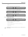
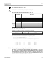
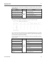
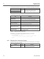
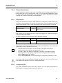
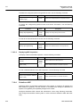
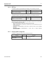
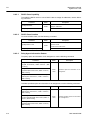
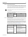
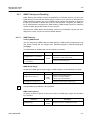
Reason for Update
Summary: Initial release
Details:
Chapter/Section
Reason for Update
All
Initial release
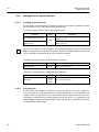
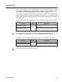
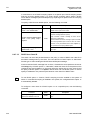
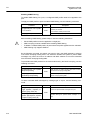
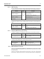
Issue History
Issue
Date of Issue
Reason for Update
05/2009
Initial release (nos 5.01 #3001)
Number
01
SMC7824M/VSW
3
CLI
Management Guide
TigerAccess™ EE
Contents
1 Introduction .......................................................................................19
1.1
1.2
1.3
1.4
1.5
1.6
Audience............................................................................................... 19
Document Structure.............................................................................. 19
Document Convention .......................................................................... 20
Document Notation............................................................................... 20
Virus Protection .................................................................................... 21
CE Declaration of Conformity ............................................................... 21
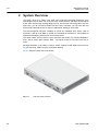
2 System Overview ..............................................................................22
2.1
System Features .................................................................................. 23
3 Command Line Interface (CLI) .........................................................25
3.1
Configuration Mode .............................................................................. 25
3.1.1
3.1.2
3.1.3
3.1.4
3.1.5
3.1.6
3.1.7
3.1.8
3.1.9
3.1.10
3.2
3.3
Privileged EXEC View Mode...................................................................... 26
Privileged EXEC Enable Mode .................................................................. 26
Global Configuration Mode ........................................................................ 27
Bridge Configuration Mode ........................................................................ 27
DHCP Pool Configuration Mode ................................................................ 28
DHCP Option Configuration Mode............................................................. 28
DHCP Option 82 Configuration Mode........................................................ 29
Interface Configuration Mode..................................................................... 29
Rule Configuration Mode ........................................................................... 30
RMON Configuration Mode........................................................................ 30
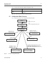
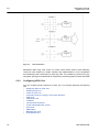
Configuration Mode Overview .............................................................. 31
Useful Tips............................................................................................ 32
3.3.1
3.3.2
3.3.3
3.3.4
3.3.5
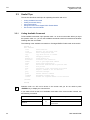
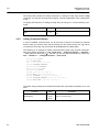
Listing Available Command........................................................................ 32
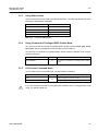
Calling Command History .......................................................................... 34
Using Abbreviation ..................................................................................... 35
Using Command of Privileged EXEC Enable Mode .................................. 35
Exit Current Command Mode .................................................................... 35
4 System Connection and IP Address ................................................36
4.1
System Connection .............................................................................. 36
4.1.1
4.1.2
4.1.3
4.1.4
4.1.5
4.1.6
Connecting to the Console Port ................................................................. 36
System Login ............................................................................................. 36
Password for Privileged EXEC Enable Mode ............................................ 37
Changing Login Password ......................................................................... 38
Login Password Recovery Process ........................................................... 39
Management for System Account .............................................................. 40
4.1.6.1
4.1.6.2
4.1.7
4.1.8
4.1.9
4.1.10
Creating System Account............................................................................... 40
Security Level ................................................................................................ 40
Limiting Number of Users........................................................................... 43
Auto Log-out............................................................................................... 44
Telnet Access ............................................................................................. 44
System Rebooting...................................................................................... 45
4.1.10.1 Manual System Rebooting............................................................................. 45
4
SMC7824M/VSW
Management Guide
TigerAccess™ EE
CLI
4.1.10.2 Auto System Rebooting .................................................................................46
4.2
System Authentication .......................................................................... 47
4.2.1
4.2.2
4.2.3
4.2.4
Authentication Method ................................................................................47
Authentication Interface ..............................................................................47
Primary Authentication Method ...................................................................47
RADIUS Server...........................................................................................48
4.2.4.1
4.2.4.2
4.2.4.3
4.2.4.4
4.2.5
TACACS+ Server ........................................................................................49
4.2.5.1
4.2.5.2
4.2.5.3
4.2.5.4
4.2.6
4.2.7
4.3
Accounting Mode ........................................................................................50
Displaying System Authentication...............................................................50
Enabling Interface .......................................................................................51
Assigning IP Address to Network Interface.................................................52
Static Route and Default Gateway..............................................................52
Interface Description ...................................................................................53
Displaying Interface ....................................................................................54
Secure Shell (SSH)............................................................................... 55
4.4.1
SSH Server .................................................................................................55
4.4.1.1
4.4.1.2
4.4.1.3
4.4.1.4
4.4.1.5
4.4.2
Login to SSH Server ......................................................................................56
File Copy ........................................................................................................56
Authentication Key .........................................................................................57
802.1x Authentication............................................................................ 58
4.5.1
802.1x Authentication..................................................................................59
4.5.1.1
4.5.1.2
4.5.1.3
4.5.1.4
4.5.1.5
4.5.1.6
4.5.1.7
4.5.1.8
4.5.2
4.5.3
Enabling 802.1x .............................................................................................59
RADIUS Server ..............................................................................................59
Authentication Mode ......................................................................................60
Authentication Port.........................................................................................61
Force Authorization ........................................................................................61
Interval for Retransmitting Request/Identity Packet .......................................61
Number of Requests to RADIUS Server ........................................................61
Interval of Request to RADIUS Server ...........................................................62
802.1x Re-Authentication............................................................................62
4.5.2.1
4.5.2.2
4.5.2.3
4.5.2.4
SMC7824M/VSW
Enabling SSH Server .....................................................................................55
Displaying On-line SSH Client........................................................................55
Disconnecting SSH Client ..............................................................................55
Assigning Specific Authentication Key............................................................56
Displaying Connection History of SSH Client .................................................56
SSH Client...................................................................................................56
4.4.2.1
4.4.2.2
4.4.2.3
4.5
TACACS+ Server for System Authentication..................................................49
TACACS+ Server Priority ...............................................................................49
Timeout of Authentication Request ................................................................49
Additional TACACS+ Configuration................................................................49
Configuring Interface............................................................................. 51
4.3.1
4.3.2
4.3.3
4.3.4
4.3.5
4.4
RADIUS Server for System Authentication ....................................................48
RADIUS Server Priority..................................................................................48
Timeout of Authentication Request ................................................................48
Frequency of Retransmit ................................................................................48
Enabling 802.1x Re-Authentication ................................................................62
Interval of Re-Authentication ..........................................................................63
Interval of Requesting Re-Authentication.......................................................63
802.1x Re-Authentication...............................................................................63
Initializing Authentication Status..................................................................64
5
CLI
Management Guide
TigerAccess™ EE
4.5.4
4.5.5
4.5.6
4.5.7
Restoring Default Value ............................................................................. 64
Displaying 802.1x Configuration ................................................................ 64
802.1x User Authentication Statistics......................................................... 64
Sample Configuration................................................................................. 65
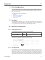
5 Port Configuration ............................................................................67
5.1
5.2
Port Basic ............................................................................................. 67
Ethernet Port Configuration .................................................................. 67
5.2.1
5.2.2
5.2.3
5.2.4
5.2.5
5.2.6
5.2.7
Enabling Ethernet Port ............................................................................... 67
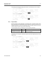
Auto-Negotiation ........................................................................................ 67
Transmit Rate............................................................................................. 68
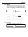
Duplex Mode .............................................................................................. 69
Flow Control ............................................................................................... 70
Port Description.......................................................................................... 70
Traffic Statistics .......................................................................................... 71
5.2.7.1
5.2.7.2
5.2.7.3
5.2.8
5.3
Port Information.......................................................................................... 74
VDSL Port Configuration ...................................................................... 75
5.3.1
Modulation of VDSL Signal ........................................................................ 75
5.3.1.1
5.3.2
5.3.3
5.3.4
Displaying Status of VDSL Port...................................................................... 77
Enabling VDSL Port ....................................................................................... 77
Profile of VDSL Port....................................................................................... 78
Controlling Power according to Connection Distance .................................... 79
PSD Level...................................................................................................... 83
PSD Mask Level ............................................................................................ 84
Interleave ....................................................................................................... 84
Impulse Noise Protection ............................................................................... 86
Trellis Coded Modulation (TCM) .................................................................... 86
Ham-band ...................................................................................................... 87
SNR Margin ................................................................................................... 88
Bitloading Per Tone........................................................................................ 90
G.handshake Tone ......................................................................................... 91
VDSL Checking Errors of VDSL Port ......................................................... 91
Config-Profile ............................................................................................. 95
5.3.4.1
5.3.4.2
5.3.5
DMT Modulation ............................................................................................ 75
Configuring VDSL Port............................................................................... 76
5.3.2.1
5.3.2.2
5.3.2.3
5.3.2.4
5.3.2.5
5.3.2.6
5.3.2.7
5.3.2.8
5.3.2.9
5.3.2.10
5.3.2.11
5.3.2.12
5.3.2.13
Line config profile........................................................................................... 95
Alarm config profile ........................................................................................ 98
Configuring CPE ...................................................................................... 102
5.3.5.1
5.3.5.2
5.3.5.3
5.3.5.4
5.3.5.5
5.3.5.6
5.3.5.7
5.3.5.8
5.3.5.9
6
Packet Statistics............................................................................................. 71
CPU Statistics ................................................................................................ 72
Protocol Statistics .......................................................................................... 73
Modem Port Reset....................................................................................... 102
Installing System Image of CPE .................................................................. 102
Installing CPE System Image File in Slave .................................................. 104
Configuring AGC (Auto Gain Control) .......................................................... 106
Checking Length of Cable between CPE and CO ....................................... 107
Auto-negotiation of CPE .............................................................................. 107
Transmit Rate of CPE .................................................................................. 107
Duplex mode of CPE ................................................................................... 107
Auto Upgrade of CPE Image ....................................................................... 108
SMC7824M/VSW
Management Guide
TigerAccess™ EE
CLI
5.3.5.10 Displaying CPE Status .................................................................................108
5.4
Port Mirroring ...................................................................................... 110
6 System Environment ...................................................................... 112
6.1
Environment Configuration ................................................................. 112
6.1.1
6.1.2
6.1.3
6.1.4
6.1.5
6.1.6
6.1.7
6.1.8
6.1.9
6.1.10
6.1.11
6.1.12
6.1.13
Host Name ................................................................................................112
Time and Date...........................................................................................112
Time Zone .................................................................................................113
Network Time Protocol (NTP) ...................................................................113
Simple Network Time Protocol (SNTP).....................................................114
Terminal Configuration ..............................................................................115
Login Banner.............................................................................................115
DNS Server ...............................................................................................116
Fan Operation ...........................................................................................117
Disabling Daemon Operation....................................................................117
FTP Server................................................................................................117
FTP Client address ...................................................................................118
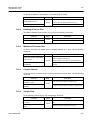
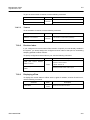
System Threshold .....................................................................................118
6.1.13.1
6.1.13.2
6.1.13.3
6.1.13.4
6.1.13.5
6.1.13.6
6.2
Configuration Management................................................................. 123
6.2.1
6.2.2
6.2.3
6.2.4
6.2.5
6.3
CPU Load .................................................................................................... 118
Port Traffic.................................................................................................... 119
Fan Operation .............................................................................................. 119
System Temperature ....................................................................................120
System Memory ...........................................................................................120
SFP Module (optional uplink port) ................................................................121
Displaying System Configuration..............................................................123
Writing System Configuration ...................................................................123
Auto-Saving...............................................................................................124
System Configuration File.........................................................................124
Restoring Default Configuration................................................................125
System Management .......................................................................... 126
6.3.1
6.3.2
6.3.3
6.3.4
6.3.5
6.3.6
6.3.7
6.3.8
6.3.9
6.3.10
6.3.11
6.3.12
6.3.13
6.3.14
6.3.15
Network Connection..................................................................................126
IP ICMP Source Routing ...........................................................................128
Tracing Packet Route................................................................................129
Displaying User Connecting to System ....................................................130
MAC Table.................................................................................................131
Running Time of System...........................................................................131
System Information ...................................................................................131
System Memory Information .....................................................................132
Running Process.......................................................................................132
Displaying System Image .........................................................................133
Displaying Installed OS.............................................................................133
Default OS.................................................................................................133
Switch Status.............................................................................................133
Tech Support Information..........................................................................134
System Boot Information...........................................................................134
7 Network Management ..................................................................... 135
7.1
Simple Network Management Protocol (SNMP)................................. 135
7.1.1
SMC7824M/VSW
SNMP Community.....................................................................................135
7
CLI
Management Guide
TigerAccess™ EE
7.1.2
7.1.3
7.1.4
7.1.5
7.1.6
7.1.7
7.1.8
Information of SNMP Agent...................................................................... 136
SNMP Com2sec....................................................................................... 137
SNMP Group ............................................................................................ 137
SNMP View Record.................................................................................. 138
Permission to Access SNMP View Record .............................................. 138
SNMP Version 3 User .............................................................................. 139
SNMP Trap............................................................................................... 139
7.1.8.1
7.1.8.2
7.1.8.3
7.1.8.4
7.1.8.5
7.1.9
SNMP Trap Mode ........................................................................................ 139
SNMP Trap Host .......................................................................................... 140
SNMP Trap in Event Mode .......................................................................... 140
Disabling SNMP Trap................................................................................... 141
Displaying SNMP Trap................................................................................. 142
SNMP Alarm............................................................................................. 143
7.1.9.1
7.1.9.2
7.1.9.3
7.1.9.4
7.1.9.5
7.1.9.6
7.1.9.7
7.1.9.8
Alarm Notify Activity ..................................................................................... 143
Alarm Severity Criterion ............................................................................... 143
Default Alarm Severity ................................................................................. 144
Generic Alarm Severity ................................................................................ 144
ADVA Alarm Severity ................................................................................... 146
ERP Alarm Severity ..................................................................................... 147
STP Guard Alarm Severity........................................................................... 147
Displaying SNMP Alarm Severity................................................................. 148
7.1.10 Displaying SNMP Configuration............................................................... 148
7.1.11 Disabling SNMP ....................................................................................... 148
7.2
Operation, Administration and Maintenance (OAM) ........................... 149
7.2.1
7.2.2
7.2.3
7.2.4
7.2.5
7.3
Link Layer Discovery Protocol (LLDP)................................................ 152
7.3.1
7.3.2
7.3.3
7.3.4
7.3.5
7.3.6
7.3.7
7.4
OAM Loopback ........................................................................................ 149
Local OAM Mode ..................................................................................... 150
OAM Unidirection ..................................................................................... 150
Remote OAM ........................................................................................... 150
Displaying OAM Configuration................................................................. 151
LLDP Operation ....................................................................................... 152
Enabling LLDP ......................................................................................... 152
LLDP Operation Type............................................................................... 153
Basic TLV ................................................................................................. 153
LLDP Message......................................................................................... 153
Reinitiating Delay ..................................................................................... 154
Displaying LLDP Configuration ................................................................ 154
Remote Monitoring (RMON)............................................................... 155
7.4.1
RMON History .......................................................................................... 155
7.4.1.1
7.4.1.2
7.4.1.3
7.4.1.4
7.4.1.5
7.4.1.6
7.4.1.7
7.4.2
RMON Alarm ............................................................................................ 158
7.4.2.1
7.4.2.2
7.4.2.3
8
Source Port of Statistical Data ..................................................................... 156
Subject of RMON History............................................................................. 156
Number of Sample Data .............................................................................. 156
Interval of Sample Inquiry ............................................................................ 157
Activating RMON History ............................................................................. 157
Deleting Configuration of RMON History ..................................................... 157
Displaying RMON History ............................................................................ 157
Subject of RMON Alarm............................................................................... 158
Object of Sample Inquiry.............................................................................. 158
Absolute and Delta Comparison .................................................................. 158
SMC7824M/VSW
Management Guide
TigerAccess™ EE
CLI
7.4.2.4
7.4.2.5
7.4.2.6
7.4.2.7
7.4.2.8
7.4.2.9
7.4.3
RMON Event .............................................................................................161
7.4.3.1
7.4.3.2
7.4.3.3
7.4.3.4
7.4.3.5
7.4.3.6
7.5
Syslog Output Level..................................................................................163
Facility Code .............................................................................................165
Syslog Bind Address .................................................................................166
Debug Message for Remote Terminal ......................................................166
Disabling Syslog .......................................................................................166
Displaying Syslog Message ......................................................................166
Displaying Syslog Configuration ...............................................................167
Quality of Service(QoS) ...................................................................... 168
7.6.1
7.6.2
How to Operate QoS.................................................................................169
Packet Classification.................................................................................171
7.6.2.1
7.6.2.2
7.6.2.3
7.6.2.4
7.6.3
7.6.4
Policy Creation .............................................................................................178
Metering .......................................................................................................179
Policy Priority ...............................................................................................185
Policy Action.................................................................................................185
Marking and Remarking ...............................................................................185
Attaching a Policy to an interface .................................................................190
Applying and Modifying Policy......................................................................190
Displaying Rule .........................................................................................190
Admin Rule................................................................................................192
7.6.6.1
7.6.6.2
7.6.6.3
7.6.6.4
7.6.7
Policer Creation............................................................................................175
Packet Counter ............................................................................................176
Average Packet Counter ..............................................................................176
Rate-limit ......................................................................................................177
Applying and modifying Policer ....................................................................178
Rule Action ................................................................................................178
7.6.4.1
7.6.4.2
7.6.4.3
7.6.4.4
7.6.4.5
7.6.4.6
7.6.4.7
7.6.5
7.6.6
Flow Creation ...............................................................................................171
Configuring Flow ..........................................................................................171
Applying and modifying Flow........................................................................174
Class Creation..............................................................................................174
Packet Conditioning ..................................................................................175
7.6.3.1
7.6.3.2
7.6.3.3
7.6.3.4
7.6.3.5
Creating Admin Flow for packet classification ..............................................192
Configuring Admin Flow ...............................................................................193
Applying and modifying Admin Flow.............................................................194
Class Creation..............................................................................................194
Admin Rule Action.....................................................................................195
7.6.7.1
SMC7824M/VSW
Event Community.........................................................................................161
Event Description .........................................................................................161
Subject of RMON Event ...............................................................................162
Event Type ...................................................................................................162
Activating RMON Event ...............................................................................162
Deleting Configuration of RMON Event........................................................162
Syslog ................................................................................................. 163
7.5.1
7.5.2
7.5.3
7.5.4
7.5.5
7.5.6
7.5.7
7.6
Upper Bound of Threshold ...........................................................................159
Lower Bound of Threshold ...........................................................................159
Standard of the First Alarm...........................................................................160
Interval of Sample Inquiry ............................................................................160
Activating RMON Alarm ...............................................................................160
Deleting Configuration of RMON Alarm........................................................161
Admin Policy Creation..................................................................................195
9
CLI
Management Guide
TigerAccess™ EE
7.6.7.2
7.6.7.3
7.6.7.4
7.6.8
7.6.9
Displaying Admin Rule ............................................................................. 197
Scheduling Algorithm ............................................................................... 198
7.6.9.1
7.6.9.2
7.6.9.3
7.6.9.4
7.6.9.5
7.6.9.6
7.6.9.7
7.7
7.8
7.9
Admin Policy Priority.................................................................................... 196
Admin Policy Action ..................................................................................... 196
Applying and Modifying Admin Policy .......................................................... 197
Scheduling Mode ......................................................................................... 200
Weight.......................................................................................................... 200
Maximum and Minimum Bandwidth ............................................................. 200
Maximum Buffer numbers............................................................................ 201
Queue Status ............................................................................................... 202
Displaying QoS ............................................................................................ 202
Weighted Random Early Detection (WRED)................................................ 203
NetBIOS Filtering................................................................................ 205
Max New Hosts .................................................................................. 206
Port Security ....................................................................................... 207
7.9.1
7.9.2
7.9.3
Port Security on Port ................................................................................ 207
Port Security Aging................................................................................... 208
Displaying Port Security ........................................................................... 209
7.10 MAC Table .......................................................................................... 209
7.11 MAC Filtering...................................................................................... 210
7.11.1
7.11.2
7.11.3
7.11.4
Default Policy of MAC Filtering ................................................................ 210
Adding Policy of MAC Filter ......................................................................211
Deleting MAC Filter Policy ....................................................................... 212
Listing of MAC Filter Policy ...................................................................... 212
7.12 Address Resolution Protocol (ARP) ................................................... 213
7.12.1 ARP Table ................................................................................................ 213
7.12.1.1 Registering ARP Table ................................................................................. 213
7.12.1.2 Displaying ARP Table................................................................................... 214
7.12.2 ARP Alias ................................................................................................. 214
7.12.3 ARP Inspection......................................................................................... 215
7.12.3.1
7.12.3.2
7.12.3.3
7.12.3.4
7.12.3.5
7.12.3.6
ARP Access List .......................................................................................... 215
Enabling ARP Inspection Filtering................................................................ 218
ARP Address Validation ............................................................................... 218
ARP Inspection on Trust Port....................................................................... 219
ARP Inspection Log-buffer ........................................................................... 219
Displaying ARP Inspection........................................................................... 220
7.12.4 Gratuitous ARP ........................................................................................ 220
7.12.5 Proxy-ARP ............................................................................................... 222
7.13 ICMP Message Control ...................................................................... 223
7.13.1 Blocking Echo Reply Message ................................................................ 224
7.13.2 Interval for Transmit ICMP Message........................................................ 224
7.14 TCP Flag Control................................................................................ 226
7.14.1 RST Configuration.................................................................................... 226
7.14.2 SYN Configuration ................................................................................... 226
7.15 Packet Dump ...................................................................................... 226
7.15.1 Packet Dump by Protocol......................................................................... 227
7.15.2 Packet Dump with Option......................................................................... 227
7.15.3 Debug Packet Dump ................................................................................ 228
7.16 sFlow Monitoring ................................................................................ 229
10
SMC7824M/VSW
Management Guide
TigerAccess™ EE
CLI
7.16.1
7.16.2
7.16.3
7.16.4
7.16.5
7.16.6
7.16.7
sFlow Service............................................................................................230
Agent IP Address ......................................................................................230
Enabling sFlow on Port .............................................................................231
Maximum IP Header Size .........................................................................231
Counter Interval ........................................................................................231
Sample Rate .............................................................................................231
Configuring Receiver ................................................................................232
7.16.7.1
7.16.7.2
7.16.7.3
7.16.7.4
7.16.7.5
Receiver ID mode ........................................................................................232
Collect IP address and port ..........................................................................232
Maximum Datagram Size .............................................................................232
Owner Name of sFlow Receiver...................................................................232
Timeout ........................................................................................................233
7.16.8 Receiver Index ..........................................................................................233
7.16.9 Displaying sFlow .......................................................................................233
8 System Main Functions .................................................................. 234
8.1
Virtual Local Area Network (VLAN)..................................................... 234
8.1.1
Port-based VLAN ......................................................................................235
8.1.1.1
8.1.1.2
8.1.1.3
8.1.1.4
8.1.2
8.1.3
8.1.4
8.1.5
8.1.6
8.1.7
8.1.8
8.1.9
Creating VLAN .............................................................................................236
Specifying PVID ...........................................................................................236
Assigning Port to VLAN................................................................................236
Deleting VLAN..............................................................................................236
Protocol-based VLAN ...............................................................................237
MAC-based VLAN.....................................................................................237
Subnet-based VLAN .................................................................................238
Tagged VLAN ............................................................................................238
VLAN Description......................................................................................239
VLAN Precedence ....................................................................................240
Displaying VLAN Information ....................................................................240
QinQ..........................................................................................................241
8.1.9.1
8.1.9.2
8.1.9.3
Double Tagging Operation............................................................................242
Double Tagging Configuration ......................................................................242
TPID Configuration.......................................................................................243
8.1.10 Layer 2 Isolation........................................................................................243
8.1.10.1 Shared VLAN ...............................................................................................244
8.1.11 VLAN Translation ......................................................................................246
8.1.12 Sample Configuration ...............................................................................246
8.2
Link Aggregation ................................................................................. 251
8.2.1
Port Trunk..................................................................................................251
8.2.1.1
8.2.1.2
8.2.1.3
8.2.2
Link Aggregation Control Protocol (LACP) ...............................................252
8.2.2.1
8.2.2.2
8.2.2.3
8.2.2.4
8.2.2.5
8.2.2.6
8.2.2.7
8.2.2.8
SMC7824M/VSW
Configuring Port Trunk .................................................................................251
Disabling Port Trunk.....................................................................................252
Displaying Port Trunk ...................................................................................252
Configuring LACP ........................................................................................253
Operation Mode ...........................................................................................254
Priority of Switch ..........................................................................................254
Manual Aggregation .....................................................................................254
BPDU Transmission Rate ............................................................................255
Administrational Key ....................................................................................255
Port Priority ..................................................................................................256
Displaying LACP Configuration ....................................................................256
11
CLI
Management Guide
TigerAccess™ EE
8.3
Spanning-Tree Protocol (STP)............................................................ 257
8.3.1
8.3.2
STP Operation ......................................................................................... 258
RSTP Operation ....................................................................................... 262
8.3.2.1
8.3.2.2
8.3.2.3
8.3.2.4
8.3.3
MSTP Operation ...................................................................................... 266
8.3.3.1
8.3.4
8.3.5
8.3.6
Root Switch.................................................................................................. 273
Path-cost...................................................................................................... 273
Port Priority .................................................................................................. 274
MST Region................................................................................................. 274
Enabling MSTP configuration ...................................................................... 276
Displaying Configuration .............................................................................. 276
Configuring PVSTP .................................................................................. 277
8.3.8.1
8.3.8.2
8.3.8.3
8.3.8.4
8.3.8.5
8.3.9
8.3.10
8.3.11
8.3.12
Path-cost Method......................................................................................... 269
Edge Ports ................................................................................................... 270
BPDU Transmit hold count........................................................................... 271
Port Priority .................................................................................................. 271
Link Type ..................................................................................................... 272
Displaying Configuration .............................................................................. 272
Configuring MSTP.................................................................................... 273
8.3.7.1
8.3.7.2
8.3.7.3
8.3.7.4
8.3.7.5
8.3.7.6
8.3.8
MSTP........................................................................................................... 267
Enabling STP Function (Required) .......................................................... 268
Configuring MSTP/PVSTP Mode ............................................................. 269
STP Basic Configuration .......................................................................... 269
8.3.6.1
8.3.6.2
8.3.6.3
8.3.6.4
8.3.6.5
8.3.6.6
8.3.7
Port States ................................................................................................... 262
BPDU Policy ................................................................................................ 263
Rapid Network Convergence ....................................................................... 263
Compatibility with 802.1d ............................................................................. 266
Enabling PVSTP .......................................................................................... 277
Root Switch.................................................................................................. 278
Path-cost...................................................................................................... 278
Port Priority .................................................................................................. 279
Displaying Configuration .............................................................................. 279
Root Guard............................................................................................... 280
Restarting Protocol Migration................................................................... 281
Loop Back Detection ................................................................................ 281
BPDU Configuration................................................................................. 282
8.3.12.1
8.3.12.2
8.3.12.3
8.3.12.4
8.3.12.5
8.3.12.6
Hello Time.................................................................................................... 283
Forward Delay Time..................................................................................... 283
Max Age....................................................................................................... 284
BPDU Hop Count......................................................................................... 284
BPDU Filtering ............................................................................................. 285
BPDU Guard................................................................................................ 285
8.3.13 Sample Configuration............................................................................... 287
8.4
Ethernet Ring Protection (ERP).......................................................... 289
8.4.1
8.4.2
8.4.3
8.4.4
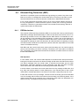
ERP Mechanism ...................................................................................... 289
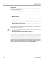
Loss of Test Packet (LOTP) ..................................................................... 293
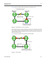
ERP Shared Link...................................................................................... 293
Configuring ERP Domain ......................................................................... 294
8.4.4.1
8.4.4.2
8.4.4.3
8.4.4.4
12
ERP Domain Name...................................................................................... 294
Primary and Secondary Port........................................................................ 294
Protected VLAN ........................................................................................... 294
Control VLAN............................................................................................... 295
SMC7824M/VSW
Management Guide
TigerAccess™ EE
CLI
8.4.4.5
8.4.4.6
8.4.5
8.4.6
8.4.7
8.4.8
8.4.9
8.4.10
8.4.11
8.4.12
8.4.13
8.5
8.6
Selecting the Node....................................................................................296
Protected Activation ..................................................................................296
Manual Switch to Secondary ....................................................................296
Wait-to-Restore Time ................................................................................297
Learning Disable Time ..............................................................................297
Test Packet Interval...................................................................................298
LOTP Hold Off Time..................................................................................298
ERP Trap...................................................................................................299
Displaying ERP Configuration...................................................................299
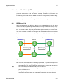
Loop Detection.................................................................................... 300
Dynamic Host Configuration Protocol (DHCP) ................................... 302
8.6.1
DHCP Server ............................................................................................303
8.6.1.1
8.6.1.2
8.6.1.3
8.6.1.4
8.6.1.5
8.6.1.6
8.6.1.7
8.6.1.8
8.6.1.9
8.6.1.10
8.6.1.11
8.6.1.12
8.6.1.13
8.6.1.14
8.6.1.15
8.6.1.16
8.6.1.17
8.6.1.18
8.6.2
8.6.3
DHCP Database Agent.................................................................................313
Displaying DHCP Lease Status....................................................................314
Deleting DHCP Lease Database..................................................................314
DHCP Relay Agent ...................................................................................315
8.6.4.1
8.6.4.2
8.6.4.3
8.6.4.4
8.6.5
DHCP Class Capability ................................................................................312
DHCP Class Creation ..................................................................................312
Relay Agent Information Pattern ..................................................................312
Associating DHCP Class..............................................................................313
Range of IP Address for DHCP Class ..........................................................313
DHCP Lease Database.............................................................................313
8.6.3.1
8.6.3.2
8.6.3.3
8.6.4
DHCP Pool Creation ....................................................................................304
DHCP Subnet...............................................................................................304
Range of IP Address ....................................................................................304
Default Gateway...........................................................................................305
IP Lease Time ..............................................................................................305
DNS Server ..................................................................................................306
Manual Binding ............................................................................................306
Domain Name ..............................................................................................307
DHCP Server Option ....................................................................................307
Static Mapping..............................................................................................307
Recognition of DHCP Client .........................................................................308
IP Address Validation ...................................................................................308
Authorized ARP............................................................................................309
Prohibition of 1:N IP Address Assignment ....................................................309
Ignoring BOOTP Request ............................................................................310
DHCP Packet Statistics ................................................................................310
Setting DHCP Pool Size............................................................................... 311
Displaying DHCP Pool Configuration ........................................................... 311
DHCP Address Allocation with Option 82 .................................................311
8.6.2.1
8.6.2.2
8.6.2.3
8.6.2.4
8.6.2.5
DHCP Helper Address..................................................................................315
Smart Relay Agent Forwarding ....................................................................316
DHCP Server ID Option ...............................................................................316
DHCP Relay Statistics..................................................................................317
DHCP Option ............................................................................................318
8.6.5.1
8.6.5.2
8.6.5.3
SMC7824M/VSW
ERP Ring Priority .........................................................................................295
Displaying ERP Domian ...............................................................................295
Entering DHCP Option Mode .......................................................................318
Configuring DHCP Option Format................................................................319
Deleting DHCP Option Format .....................................................................319
13
CLI
Management Guide
TigerAccess™ EE
8.6.5.4
8.6.6
8.6.6.1
8.6.6.2
8.6.6.3
8.6.6.4
8.6.7
Enabling DHCP Snooping............................................................................ 324
DHCP Trust State......................................................................................... 324
DHCP Rate Limit ......................................................................................... 325
DHCP Lease Limit ....................................................................................... 325
Source MAC Address Verification ................................................................ 326
Static DHCP Snooping Binding.................................................................... 326
DHCP Snooping Database Agent ................................................................ 326
DHCP Snooping Filtering............................................................................. 327
Authorized ARP ........................................................................................... 328
DHCP Snooping with Option82.................................................................... 329
DHCP Snooping Option ............................................................................... 329
DHCP User Class ID.................................................................................... 330
Displaying DHCP Snooping Configuration................................................... 331
IP Source Guard ...................................................................................... 331
8.6.8.1
8.6.8.2
8.6.8.3
8.6.9
Enabling DHCP Option 82 ........................................................................... 321
Option 82 Sub-Option .................................................................................. 321
Option 82 Reforwarding Policy .................................................................... 322
Option 82 Trust Policy.................................................................................. 323
DHCP Snooping ....................................................................................... 323
8.6.7.1
8.6.7.2
8.6.7.3
8.6.7.4
8.6.7.5
8.6.7.6
8.6.7.7
8.6.7.8
8.6.7.9
8.6.7.10
8.6.7.11
8.6.7.12
8.6.7.13
8.6.8
Displaying DHCP option .............................................................................. 319
DHCP Option 82 ...................................................................................... 320
Enabling IP Source Guard ........................................................................... 332
Static IP Source Binding .............................................................................. 332
Displaying IP Source Guard Configuration .................................................. 333
DHCP Client ............................................................................................. 334
8.6.9.1
8.6.9.2
8.6.9.3
8.6.9.4
8.6.9.5
8.6.9.6
8.6.9.7
8.6.9.8
Enabling DHCP Client.................................................................................. 334
DHCP Client ID............................................................................................ 334
DHCP Class ID ............................................................................................ 334
Host Name................................................................................................... 334
IP Lease Time.............................................................................................. 335
Requesting Option ....................................................................................... 335
Forcing Release or Renewal of DHCP Lease.............................................. 335
Displaying DHCP Client Configuration......................................................... 335
8.6.10 DHCP Filtering ......................................................................................... 336
8.6.10.1 DHCP Packet Filtering ................................................................................. 336
8.6.10.2 DHCP Server Packet Filtering ..................................................................... 336
8.6.11 Debugging DHCP..................................................................................... 337
8.7
Single IP Management ....................................................................... 338
8.7.1
8.7.2
8.7.3
8.7.4
8.7.5
8.7.6
8.8
8.9
Switch Group............................................................................................ 338
Designating Master and Slave Switch ..................................................... 339
Disabling Stacking.................................................................................... 339
Displaying Stacking Status ....................................................................... 339
Accessing to Slave Switch from Master Switch ....................................... 340
Sample Configuration............................................................................... 340
Rate Limit ........................................................................................... 342
Flood Guard........................................................................................ 343
8.9.1
8.9.2
8.9.3
MAC Flood-Guard .................................................................................... 343
CPU Flood-Guard .................................................................................... 344
Port Flood-Guard ..................................................................................... 345
8.10 Storm Control...................................................................................... 346
14
SMC7824M/VSW
Management Guide
TigerAccess™ EE
CLI
8.11 Jumbo Frame Capacity....................................................................... 346
8.12 Bandwidth ........................................................................................... 347
8.13 Maximum Transmission Unit (MTU).................................................... 347
9 IP Multicast ...................................................................................... 348
9.1
Multicast Group Membership .............................................................. 349
9.1.1
IGMP Basic ...............................................................................................349
9.1.1.1
9.1.1.2
9.1.2
IGMP Version 2 .........................................................................................351
9.1.2.1
9.1.3
9.2
Clearing IGMP Entry ....................................................................................350
IGMP Debug ................................................................................................350
IGMP Static Join...........................................................................................352
IGMP Version 3 .........................................................................................353
Multicast Functions ............................................................................. 354
9.2.1
Multicast Forwarding Database ................................................................354
9.2.1.1
9.2.1.2
9.2.1.3
9.2.2
IGMP Snooping Basic...............................................................................356
9.2.2.1
9.2.2.2
9.2.2.3
9.2.3
Enabling MVR ..............................................................................................369
MVR Group ..................................................................................................369
Source/Receiver Port ...................................................................................370
MVR Helper Address....................................................................................370
Displaying MVR Configuration .....................................................................370
IGMP Filtering and Throttling ....................................................................371
9.2.7.1
9.2.7.2
9.2.7.3
9.2.8
IGMP Snooping Querier Configuration.........................................................358
IGMP Snooping Last Member Query Interval...............................................360
IGMP Snooping Immediate Leave ...............................................................361
IGMP Snooping Report Suppression ...........................................................362
IGMP Snooping S-Query Report Agency .....................................................362
Explicit Host Tracking...................................................................................363
Multicast Router Port Configuration .............................................................364
TCN Multicast Flooding ................................................................................366
IGMPv3 Snooping.....................................................................................367
Displaying IGMP Snooping Information....................................................368
Multicast VLAN Registration (MVR)..........................................................369
9.2.6.1
9.2.6.2
9.2.6.3
9.2.6.4
9.2.6.5
9.2.7
Enabling IGMP Snooping .............................................................................357
IGMP Snooping Version ...............................................................................357
IGMP Snooping Robustness Value ..............................................................358
IGMPv2 Snooping.....................................................................................358
9.2.3.1
9.2.3.2
9.2.3.3
9.2.3.4
9.2.3.5
9.2.3.6
9.2.3.7
9.2.3.8
9.2.4
9.2.5
9.2.6
Blocking Unknown Multicast Traffic..............................................................355
Forwarding Entry Aging................................................................................355
Displaying McFDB Information.....................................................................355
IGMP Filtering ..............................................................................................371
IGMP Throttling ............................................................................................373
Displaying IGMP Filtering and Throttling ......................................................373
Multicast-Source Trust Port.......................................................................373
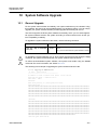
10 System Software Upgrade.............................................................. 375
10.1 General Upgrade ................................................................................ 375
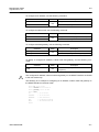
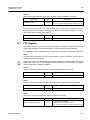
10.2 Boot Mode Upgrade............................................................................ 376
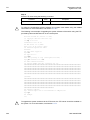
10.3 FTP Upgrade ...................................................................................... 379
11 Abbreviations .................................................................................. 381
SMC7824M/VSW
15
CLI
Management Guide
TigerAccess™ EE
Illustrations
Fig. 2.1
Fig. 3.1
Fig. 4.1
Fig. 4.2
Fig. 5.1
Fig. 5.2
Fig. 5.3
Fig. 5.4
Fig. 5.5
Fig. 6.1
Fig. 6.2
Fig. 7.1
Fig. 7.2
Fig. 7.3
Fig. 7.4
Fig. 7.5
Fig. 7.6
Fig. 7.7
Fig. 7.8
Fig. 7.9
Fig. 7.10
Fig. 7.11
Fig. 7.12
Fig. 7.13
Fig. 7.14
Fig. 7.15
Fig. 7.16
Fig. 7.17
Fig. 7.18
Fig. 8.1
Fig. 8.2
Fig. 8.3
Fig. 8.4
Fig. 8.5
Fig. 8.6
Fig. 8.7
Fig. 8.8
Fig. 8.9
Fig. 8.10
Fig. 8.11
Fig. 8.12
Fig. 8.13
Fig. 8.14
Fig. 8.15
Fig. 8.16
Fig. 8.17
Fig. 8.18
Fig. 8.19
Fig. 8.20
16
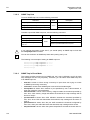
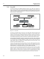
The front view of switch................................................................................. 22
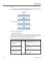
Overview of Configuration Mode ................................................................... 31
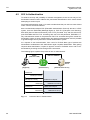
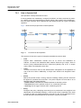
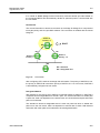
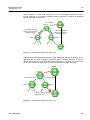
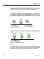
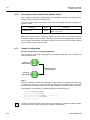
Process of 802.1x Authentication.................................................................. 58
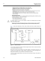
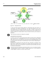
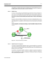
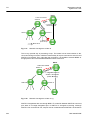
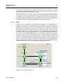
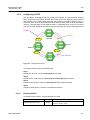
Multiple Authentication Servers ..................................................................... 59
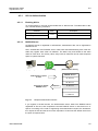
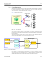
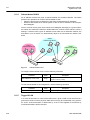
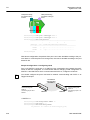
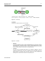
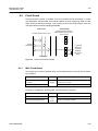
Transmission in DSL System ........................................................................ 75
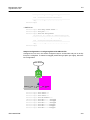
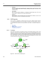
DMT Modulation ............................................................................................ 76
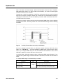
Deciding Transmit Rate according to SNR Margin........................................ 89
Counting Times of Error ................................................................................ 92
Port Mirroring................................................................................................110
Ping Test for Network Status ....................................................................... 128
IP Source Routing ....................................................................................... 129
Procedure of QoS operation........................................................................ 169
Structure of Rule.......................................................................................... 170
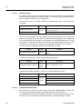
Token Bucket Meter..................................................................................... 180
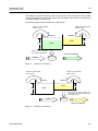
Behavior of srTCM (1) ................................................................................. 181
Behavior of srTCM (2) ................................................................................. 181
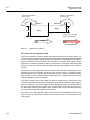
Bahavior of srTCM (3) ................................................................................. 182
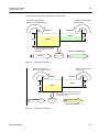
Behavior of trTCM (1).................................................................................. 183
Behavior of trTCM (2).................................................................................. 183
Behavior of trTCM (3).................................................................................. 184
Marking and Remarking .............................................................................. 186
Strict Priority Queuing.................................................................................. 198
Deficit Weighted Round Robin .................................................................... 199
WRED Packet Drop Probability................................................................... 203
NetBIOS Filtering ........................................................................................ 205
Proxy-ARP................................................................................................... 222
ICMP Message Structure ............................................................................ 223
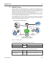
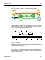
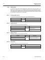
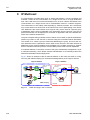
sFlow Structure............................................................................................ 229
sFlow Agent Diagram .................................................................................. 229
Port-based VLAN ........................................................................................ 235
Subnet-based VLAN.................................................................................... 238
Example of QinQ Configuration................................................................... 241
QinQ Frame................................................................................................. 241
Outgoing Packets under Layer 2 Shared VLAN Environment .................... 244
Incoming Packets under Layer 2 Shared VLAN Environment (1)............... 245
Incoming Packets under Layer 2 Shared VLAN Environment (2)............... 245
Link Aggregation.......................................................................................... 251
Example of Loop ......................................................................................... 257
Principle of Spanning Tree Protocol ............................................................ 258
Root Switch ................................................................................................. 259
Designated Switch....................................................................................... 260
Port Priority.................................................................................................. 261
Port State..................................................................................................... 261
Alternate Port and Backup port ................................................................... 262
Example of Receiving Low BPDU ............................................................... 263
Network Convergence of 802.1d................................................................. 264
Network Convergence of 802.1w (1)........................................................... 264
Network Convergence of 802.1w (2)........................................................... 265
Network Convergence of 802.1w (3)........................................................... 265
SMC7824M/VSW
Management Guide
TigerAccess™ EE
CLI
Fig. 8.21
Fig. 8.22
Fig. 8.23
Fig. 8.24
Fig. 8.25
Fig. 8.26
Fig. 8.27
Fig. 8.28
Fig. 8.29
Fig. 8.30
Fig. 8.31
Fig. 8.32
Fig. 8.33
Fig. 8.34
Fig. 8.35
Fig. 8.36
Fig. 8.37
Fig. 8.38
Fig. 8.39
Fig. 9.1
Fig. 9.2
SMC7824M/VSW
Compatibility with 802.1d (1)........................................................................266
Compatibility with 802.1d (2)........................................................................266
CST and IST of MSTP (1) ............................................................................267
CST and IST of MSTP (2) ............................................................................268
Example of PVSTP.......................................................................................277
Root Guard...................................................................................................280
Example of Layer 2 Network Design in RSTP Environment ........................287
Example of Layer 2 Network Design in MSTP Environment........................288
ERP Operation in case of Linnk Failure .......................................................291
Ring Protection.............................................................................................291
Link Failure Recovery ..................................................................................292
Ring Recovery..............................................................................................292
Shared Link ..................................................................................................293
DHCP Service Structure...............................................................................302
Example of DHCP Relay Agent....................................................................315
DHCP Option 82 Operation..........................................................................321
DHCP Server Packet Filtering......................................................................337
Example of Single IP management..............................................................338
Rate Limit and Flood Guard .........................................................................343
IGMP Snooping in the L2 network ...............................................................348
IGMP Snooping ............................................................................................356
17
CLI
Management Guide
TigerAccess™ EE
Tables
Tab. 1.1
Tab. 1.2
Tab. 3.1
Tab. 3.2
Tab. 3.3
Tab. 3.4
Tab. 3.5
Tab. 3.6
Tab. 3.7
Tab. 3.8
Tab. 3.9
Tab. 3.10
Tab. 3.11
Tab. 5.1
Tab. 5.2
Tab. 5.3
Tab. 5.4
Tab. 5.5
Tab. 5.6
Tab. 5.7
Tab. 5.8
Tab. 5.9
Tab. 6.1
Tab. 6.2
Tab. 6.3
Tab. 6.4
Tab. 7.1
Tab. 7.2
Tab. 7.3
Tab. 8.1
Tab. 8.2
Tab. 8.3
18
Overview of Chapters.................................................................................... 19
Command Notation of Guide Book................................................................ 20
Main Command of Privileged EXEC View Mode .......................................... 26
Main Command of Privileged EXEC Enable Mode ....................................... 26
Main Command of Global Configuration Mode ............................................. 27
Main Command of Bridge Configuration Mode ............................................. 28
Main Command of DHCP Pool Configuration Mode ..................................... 28
Main Command of DHCP Option Configuration Mode.................................. 29
Main Command of DHCP Option 82 Configuration Mode............................. 29
Main Command of Interface Configuration Mode ......................................... 30
The Commands of Rule Configuration Mode................................................ 30
Main Command of RMON Configuration Mode ............................................ 31
Command Abbreviation ................................................................................. 35
Information displayed by Command, show lre .............................................. 77
Profile of VDSL Port ...................................................................................... 78
Option band of VDSL Port ............................................................................. 79
Value of PBO-Length..................................................................................... 81
The frequency of PSD Level per band .......................................................... 83
The Value of PSD Mask Level....................................................................... 84
Bandwidth of Ham band Frequency.............................................................. 88
Sub-commands in Bitloading Per Tone ......................................................... 91
NOS Download............................................................................................ 109
World Time Zone ..........................................................................................113
Options for Ping........................................................................................... 126
Options for Ping for Multiple IP Addresses.................................................. 127
Options for Tracing Packet Route ............................................................... 130
ICMP Message Type ................................................................................... 223
Mask Calculation of Default Value............................................................... 225
Options for Packet Dump ............................................................................ 227
Advantages and Disadvantages of Tagged VLAN ...................................... 239
STP Path-cost (short) .................................................................................. 269
RSTP Path-cost (long) ................................................................................ 270
SMC7824M/VSW
Management Guide
TigerAccess™ EE
CLI
1 Introduction
1.1
Audience
This manual is intended for Ethernet/IP DSLAM operators and maintenance personnel for
providers of Digital Subscriber Line(DSL) and Ethernet services. This manual assumes
that you are familiar with the following:
• Ethernet networking technology and standards
• Internet topologies and protocols
• DSL technology and standards
• Usage and functions of graphical user interfaces.
1.2
Document Structure
Tab. 1.1 briefly describes the structure of this document.
Chapter
1 Introduction
Introduces the overall information of the document.
2 System Overview
Introduces the switch system. It also lists the features of the system.
3 Command Line Interface (CLI)
Describes how to use the Command Line Interface (CLI).
4 System Connection and IP Address
Describes how to manage the system account and IP address.
5 Port Configuration
Describes how to configure the Ethernet or VDSL ports.
6 System Environment
Describes how to configure the system environment and management functions.
7 Network Management
Describes how to configure the network management functions.
8 System Main Functions
Describes how to configure the system main functions.
9 IP Multicast
Describes how to configure the IP multicast functions.
10 System Software Upgrade
Describes how to upgrade the system software.
11 Abbreviations
Tab. 1.1
SMC7824M/VSW
Description
Lists all abbreviations and acronyms which appear in this document.
Overview of Chapters
19
CLI
Management Guide
TigerAccess™ EE
1.3
Document Convention
This guide uses the following conventions to convey instructions and information.
Information
i
This information symbol provides useful information when using commands to configure
and means reader take note. Notes contain helpful suggestions or references.
Warning
!
1.4
This warning symbol means danger. You are in a situation that could cause bodily injury
or broke the equipment. Before you work on any equipment, be aware of the hazards involved with electrical circuitry and be familiar with standard practices for preventing accidents by making quick guide based on this guide.
Document Notation
The following table shows commands used in guide book. Please be aware of each
command to use them correctly.
Notation
a
Commands you should use as is.
NAME, PROFILE, VALUE, …
Variables for which you supply values.
PORTS
For entry this variable, see Section 5.1.
[]
<>
{}
|
Tab. 1.2
20
Description
Commands or variables that appear within square brackets [ ] are
optional.
Range of number that you can use.
A choice of required keywords appears in braces { }. You must select one.
Optional variables are separated by vertical bars |.
Command Notation of Guide Book
SMC7824M/VSW
Management Guide
TigerAccess™ EE
1.5
!
CLI
Virus Protection
To prevent a virus infection you may not use any software other than that which is released for the Operating System (OS based on Basis Access Integrator), Local Craft
Terminal (LCT) and transmission system.
Even when exchanging data via network or external data media(e.g. floppy disks) there is
a possibility of infecting your system with a virus. The occurrence of a virus in your system may lead to a loss of data and breakdown of functionality.
!
The operator is responsible for protecting against viruses, and for carrying out repair procedures when the system is infected.
You have to do the following:
• You have to check every data media (used data media as well as new ones) for virus
before reading data from it.
• You must ensure that a current valid virus scanning program is always available. This
program has to be supplied with regular updates by a certified software.
• It is recommended that you make periodic checks against viruses in your OS.
• At the LCT it is recommended to integrate the virus scanning program into the startup
sequence.
1.6
CE Declaration of Conformity
The CE declaration of the product will be fulfilled if the construction and cabling is undertaken in accordance with the manual and the documents listed there in, e.g. mounting instructions, cable lists where necessary account should be taken of project-specific documents.
Deviations from the specifications or unstipulated changes during construction, e.g. the
use of cable types with lower screening values can lead to violation of the CE requirements. In such case the conformity declaration is invalidated and the responsibility
passes to those who have caused the deviations.
!
SMC7824M/VSW
This is a class A product. In a domestic environment this product may cause radio reference in which case the user may be required to take adequate measures.
21
CLI
Management Guide
TigerAccess™ EE
2 System Overview
The switch, which is IP VDSL, uses VDSL (Very high-data rate Digital Subscriber Line)
technologies so that users can be served voice communication and data communication
at the same time through existing telephone line. Since VDSL technology takes the telephone line, you do not need to install LAN line newly. Therefore, you can save the cost
and provide advanced service for users in apartments, buildings, and hotels.
The switch supports maximum 100Mbps of upload and 100Mbps down load in case of
Symmetric, and up to 50 Mbps of upload and 100 Mbps of download or 10VLR Mbps of
upload 50VLR Mbps of download in case of Asymmetric.
The switch offers 24-Port VDSL2 service interface and fixed 2-Port 10/100/1000Base-T
and 1-slot for option uplink module. Note – The uplink module is not used in the first release.
Managed switches, as IP-VDSL of Layer 2 switch, supports VLAN, Rate limit, port trunking, port mirroring, IGMP snooping, and packet filtering.
Fig. 2.1 shows the front view of the switch.
Fig. 2.1
22
The front view of switch
SMC7824M/VSW
Management Guide
TigerAccess™ EE
2.1
CLI
System Features
The following introduces the main features of the VDSL2 system which provides Layer 2
switching, Ethernet switching and related functions.
Virtual Local Area Network (VLAN)
Virtual local area network (VLAN) is made by dividing one network into several logical
networks. Packet cannot be transmitted and received between different VLANs. Therefore, it can prevent needless packets accumulating and strengthen security. The switch
recognizes 802.1Q tagged frame and supports maximum 4096 VLANs. Port based, Protocol based, MAC based and Subnet based VLANs are supported in the switch.
Quality of Service (QoS)
For the switch, QoS-based forwarding sorts traffic into a number of classes and marks the
packets accordingly. Thus, different quality of service is provided to each class, which the
packets belong to. The rich QoS capabilities enable network managers to protect missioncritical applications and support differentiated level of bandwidth for managing traffic congestion. The switch supports ingress and egress (shaping) rate limiting, and different
scheduling type such as SP (Strict Priority) and DWRR (Weighted Deficit Round Robin).
IP Multicast
Because broadcasting in a LAN is restricted if possible, multicasting could be used instead of broadcasting by forwarding multicast packets only to the member hosts who
joined multicast group. The switch provides IGMPv2 and IGMP snooping for host membership management.
SNMP
Simple network management protocol (SNMP) is to manage Network Elements using
TCP/IP protocol. The switch supports SNMP version 1, 2, 3 and Remote Monitoring
(RMON). Network operator can use MIB also to monitor and manage the switch.
Dynamic Host Configuration Protocol (DHCP)
The switch supports Dynamic Host Configuration Protocol (DHCP) server that automatically assigns IP address to clients accessed to network. That means it has IP address
pool, and operator can effectively utilize limited IP source by leasing temporary IP address. In layer 3 network, DHCP request packet can be sent to DHCP server via DHCP
relay and option 82.
Spanning Tree Protocol (STP)
To prevent loop and preserve backup route in Layer 2 network, the switch supports spanning tree protocol (STP) defined in IEEE 802.1D. Between STP enabled switches, a root
bridge is automatically selected and the network remains in tree topology. But the recovery time in STP is very slow (about 30 seconds), rapid spanning tree protocol (RSTP) is
also provided. IEEE 802.1w defines the recovery time as 2 seconds. If there is only one
SMC7824M/VSW
23
CLI
Management Guide
TigerAccess™ EE
VLAN in the network, traditional STP works. However in more than one VLAN network,
STP cannot work per VLAN. To avoid this problem, the switch supports multiple spanning
tree protocol (MSTP) IEEE 802.1s.
Trunking & Link Aggregation Control Protocol (LACP)
The switch aggregates several physical interfaces into one logical port (aggregate port).
Port trunk aggregates interfaces with the standard of same speed, same duplex mode,
and same VLAN ID.
The switch supports link aggregation control protocol (LACP), complying with IEEE
802.3ad, which aggregates multiple links of equipments to use more enlarged bandwidth.
System Management based on CLI
It is easy for users who administer system by using telnet or console port to configure the
functions for system operating through CLI. CLI is easy to configure the needed functions
after looking for available commands by help menu different with UNIX.
Broadcast Storm Control
Broadcast storm control is, when too much of broadcast packets are being transmitted to
network, a situation of network timeout because the packets occupy most of transmit capacity. switch supports broadcast and multicast storm control, which disuses flooding
packet, that exceed the limit during the time configured by user.
Outband Management Interface
The switch can connect to equipments at remote place by assigning IP address to MGMT
interface. Since MGMT interface is operated regardless of status of service port, it is still
possible to configure and manage equipment at remote place.
RADIUS and TACACS+
The switch supports client authentication protocol, that is RADIUS (Remote Authentication Dial-In User Service) and TACACS+ (Terminal Access Controller Access Control System Plus). Not only user IP and password registered in switch but also authentication
through RADIUS server and TACACS+ server are required to access. So security of system and network management is strengthened.
Secure Shell (SSH)
Network security is getting more important because the access network has been generalized among numerous users. Secure shell (SSH) is a network protocol that allows establishing a secure channel between a local and a remote computer. It uses public-key
cryptography to authenticate the remote computer and to allow the remote computer to
authenticate the user.
24
SMC7824M/VSW
Management Guide
TigerAccess™ EE
CLI
3 Command Line Interface (CLI)
The switch enables system administrators to manage the switch by providing the command line interface (CLI). This user-friendly CLI provides you with a more convenient
management environment.
To manage the system with the CLI, a management network environment is required. The
switch can connect to the management network either directly (outband) or through the
access network (inband). It can even connect using a combination of the two; for example,
a cascaded switch connects inband to the cascading switch, and then from the cascading
switch to the management network through the outband interface.
The switch also provides the RS232 console interface to simply access the system with a
provided RJ45-to-DB9 cable.
This chapter describes a basic instruction for using the command line interface (CLI)
which is used for managing the system.
•
•
•
3.1
Configuration Mode
Configuration Mode Overview
Useful Tips
Configuration Mode
You can configure and manage the switch with the CLI via a management network environment or the console interface.
The CLI provides the following command modes:
• Privileged EXEC View Mode
• Privileged EXEC Enable Mode
• Global Configuration Mode
• Bridge Configuration Mode
• DHCP Pool Configuration Mode
• DHCP Option 82 Configuration Mode
• Interface Configuration Mode
• Rule Configuration Mode
• RMON Configuration Mode
SMC7824M/VSW
25
CLI
Management Guide
TigerAccess™ EE
3.1.1
Privileged EXEC View Mode
When you log in to the switch, the CLI will start with Privileged EXEC View mode which is
a read-only mode. In this mode, you can see a system configuration and information with
several commands.
Tab. 3.1 shows main command of Privileged EXEC View mode.
Command
enable
Opens Privileged EXEC Enable mode.
exit
Logs out the switch.
show
Shows a system configuration and information.
Tab. 3.1
3.1.2
Description
Main Command of Privileged EXEC View Mode
Privileged EXEC Enable Mode
To configure the switch, you need to open Privileged EXEC Enable mode with the enable
command, then the system prompt will changes from SWITCH> to SWITCH#.
Command
enable
Mode
View
Description
Opens Privileged EXEC Enable mode.
You can set a password to Privileged EXEC Enable mode to enhance security. Once setting a password, you should enter a configured password, when you open Privileged EXEC Enable mode.
Tab. 3.2 shows main commands of Privileged EXEC Enable mode.
Command
clock
Sets a system time and date.
configure terminal
Opens Global Configuration mode.
reload
Reboots the system.
telnet
Connects to a remote host through telnet.
terminal length
Configures the number of lines of the current terminal.
traceroute
Traces a packet route.
where
Displays users accessing the system via telnet or console.
Tab. 3.2
26
Description
Main Command of Privileged EXEC Enable Mode
SMC7824M/VSW
Management Guide
TigerAccess™ EE
3.1.3
CLI
Global Configuration Mode
In Global Configuration mode, you can configure general functions of the system. You can
also open another configuration mode from this mode.
To open Global Configuration mode, enter the configure terminal command, and then
the system prompt will be changed from SWITCH# to SWITCH(config)#.
Command
configure terminal
Mode
Enable
Description
Opens Global Configuration mode.
Tab. 3.3 shows main commands of Global Configuration mode.
Command
bridge
Opens Bridge Configuration mode.
dns
Sets a DNS server.
dot1x
Configures 802.1X authentication.
exec-timeout
Sets an auto log-out timer.
help
Shows a description of the interactive help system.
hostname
Sets a host name of the system.
interface
Opens Interface Configuration mode to configure a specified interface.
mvr
Configures MVR.
ntp
Configures NTP.
passwd
Sets a system password.
qos
Configures QoS.
rmon-alarm
Opens RMON Configuration mode to configure RMON alarm.
snmp
Configures SNMP.
ssh
Configures SSH.
stack
Configures a system stacking.
syslog
Configures a syslog.
threshold
Sets a system threshold.
Tab. 3.3
3.1.4
Description
Main Command of Global Configuration Mode
Bridge Configuration Mode
In Bridge Configuration mode, you can configure various Layer 2 functions such as VLAN,
STP, LACP, EFM OAM, etc.
To open Bridge Configuration mode, enter the bridge command, then the system prompt
will be changed from SWITCH(config)# to SWITCH(bridge)#.
Command
bridge
SMC7824M/VSW
Mode
Global
Description
Opens Bridge Configuration mode.
27
CLI
Management Guide
TigerAccess™ EE
Tab. 3.4 shows main commands of Bridge Configuration mode.
Command
lacp
Configures LACP.
mac
Configures a MAC table.
mirror
Configures a port mirroring.
oam
Configures EFM OAM.
port
Configures Ethernet port.
spanning-tree
Configures Spanning Tree Protocol (STP).
trunk
Configures a trunk port.
vlan
Configures VLAN.
Tab. 3.4
3.1.5
Description
Main Command of Bridge Configuration Mode
DHCP Pool Configuration Mode
In DHCP Pool Configuration mode, you can configure general functions of DHCP per
each DHCP pool. The switch supports multiple DHCP environments with this pool based
DHCP configuration.
To open DHCP Pool Configuration mode, enter the ip dhcp pool command, then the system prompt will be changed from SWITCH(config)# to SWITCH(config-dhcp[POOL])#.
Command
ip dhcp pool POOL
!
Mode
Global
Description
Opens DHCP Pool Configuration mode to configure
DHCP.
To open DHCP Pool Configuration mode, use the service dhcp command in the Global
Configuration mode first!
Tab. 3.5 shows main commands of DHCP Pool Configuration mode.
Command
default-router
Configures the default gateway of the pool.
dns-server
Configures a DNS server.
range
Configures the range of IP addresses.
Tab. 3.5
3.1.6
Description
Main Command of DHCP Pool Configuration Mode
DHCP Option Configuration Mode
In DHCP Option Configuration mode, you can configure DHCP option. You can define
DHCP options that are carried in the DHCP communication between DHCP server and
client or relay agent. A specific DHCP option can be defined by its format type, length and
value.
28
SMC7824M/VSW
Management Guide
TigerAccess™ EE
CLI
To open DHCP Option Configuration mode, use the command. Then the system prompt
will be changed from SWITCH(config)# to SWITCH(dhcp-opt[NAME])#.
Command
ip dhcp option format NAME
Mode
Global
Description
Opens DHCP Option Configuration mode to configure
DHCP options.
Tab. 3.7 is the main commands of DHCP Option Configuration mode.
Command
attr
Tab. 3.6
3.1.7
Description
Configures the attribute for option field in the DHCP packet.
Main Command of DHCP Option Configuration Mode
DHCP Option 82 Configuration Mode
In DHCP Option 82 Configuration mode, you can configure DHCP option 82 for DHCP relay agent. This feature enables network administrators to manage IP resources more efficiently.
To open DHCP Option 82 Configuration mode, enter the ip dhcp option82 command,
then the system prompt will be changed from SWITCH(config)# to SWITCH(configopt82)#.
Command
ip dhcp option82
!
Mode
Global
Description
Opens DHCP Option 82 Configuration mode to configure DHCP option 82.
To open DHCP Option 82 Configuration mode, use the service dhcp command in the
Global Configuration mode first!
Tab. 3.7 is the main commands of DHCP Option 82 Configuration mode.
Command
policy
Configures the policy for option 82 field in the DHCP packet.
system-remote-id
Configures a system remote ID.
system-circuit-id
Configures a system circuit ID.
trust
Configures a option82 packet of policy
Tab. 3.7
3.1.8
Description
Main Command of DHCP Option 82 Configuration Mode
Interface Configuration Mode
In Interface Configuration mode, you can configure Ethernet interfaces. To open Interface
Configuration mode, enter the interface command, then the system prompt will be
changed from SWITCH(config)# to SWITCH(config-if)#.
SMC7824M/VSW
Command
Mode
interface INTERFACE
Global
Description
Opens Interface Configuration mode.
29
CLI
Management Guide
TigerAccess™ EE
Tab. 3.8 shows main commands of Interface Configuration mode.
Command
description
Specifies a description.
ip address
Assigns IP address.
shutdown
Deactivates an interface.
mtu
Sets MTU value.
Tab. 3.8
3.1.9
Description
Main Command of Interface Configuration Mode
Rule Configuration Mode
The switch modifies previous Rule Configuration mode to Flow, Policer and Policy Configuration modes. Rule configuration mode is expanded into three different modes according to its roles for Rule mechanism. You can configure a rule for incoming or outgoing
packets. Using the function, you can handle packets classified by the rule.
To open Rule Configuration mode, enter the flow, policer and policy commands, then
the system prompt will be changed from SWITCH(config)# to SWITCH(configflow[NAME])#, SWITCH(config-policer[NAME])# and SWITCH(config-policy[NAME])# .
Command
Mode
flow NAME create
policer NAME create
Description
Opens Flow Configuration mode.
Global
policy NAME create
Opens Policer Configuration mode.
Opens Policy Configuration mode.
Tab. 3.9 shows the commands of Rule Configuration mode.
Command
cos
Classifies an IEEE 802.1p priority.
mac
Classifies a MAC address.
action match
Configures a rule action for classified packets.
rate-limit
Comfigures a rate-limit of classified packets
priority
Configures a rule priority of specified policy.
Tab. 3.9
3.1.10
Description
The Commands of Rule Configuration Mode
RMON Configuration Mode
In RMON Configuration mode, you can configure RMON alarm, RMON event and RMON
history. The switch provides three different configuration modes to configure each type of
RMON.
Command
Mode
Description
rmon-alarm <1-65535>
rmon-event <1-65535>
Global
Opens RMON Configuration mode.
1-65535: index number
rmon-history <1-65535>
30
SMC7824M/VSW
Management Guide
TigerAccess™ EE
CLI
Tab. 3.10 shows main commands of RMON Configuration mode.
Command
Description
active
Activates RMON.
Shows the subject which configures each RMON and uses relevant
owner
Tab. 3.10
3.2
information.
Main Command of RMON Configuration Mode
Configuration Mode Overview
Fig. 3.1 shows the overview of the configuration mode for the switch.
Privileged EXEC View
SWITCH>
exit
Back to previous mode
enable
end
Back to Privileged EXEC Enable mode
Privileged EXEC Enable
SWITCH#
configure terminal
Global Configuration mode
SWITCH(config)#
ip dhcp pool POOL
(POOL: pool name)
DHCP Pool Configuration mode
SWITCH(config-dhcp[POOL])#
interface INTERFACE
INTERFACE: interface name
Interface Configuration mode
SWITCH(config-if)#
bridge
ip dhcp option82
Option 82 Configuration mode
SWITCH(config-opt82)#
rmon-alarm <1-65535>
rmon-event <1-65535>
rmon-history <1-65535>
RMON Configuration mode
SWITCH(config-rmonalarm[N])#
SWITCH(config-rmonevent[N])#
SWITCH(config-rmonhistory[N])#
Fig. 3.1
Bridge Configuration mode
SWITCH(bridge)#
flow [admin] NAME create (NAME: flow name)
policer NAME create (NAMEL policer name)
policy [admin] NAME create (NAME: policy name)
Rule Configuration mode
SWITCH(config-flow[NAME])#
SWITCH(config-policer[NAME])#
SWITCH(config-policy[NAME])#
Overview of Configuration Mode
SMC7824M/VSW
31
CLI
Management Guide
TigerAccess™ EE
3.3
Useful Tips
This section describes useful tips for operating the switch with a CLI.
•
•
•
•
•
3.3.1
Listing Available Command
Calling Command History
Using Abbreviation
Using Command of Privileged EXEC Enable Mode
Exit Current Command Mode
Listing Available Command
To list available commands, input question mark <?> in the current mode. When you input
the question mark <?>, you can see available commands used in this mode and variables
following after the commands.
The following is the available commands on Privileged EXEC Enable mode of the switch.
SWITCH# ?
Exec commands:
clear
Reset functions
clock
Manually set the system clock
configure
Enter configuration mode
copy
Copy from one file to another
debug
Debugging functions
default-os
Select default OS
disconnect
Disconnect user connection
enable
Turn on privileged mode command
erase
Erase saved configuration
exit
End current mode and down to previous mode
halt
Halt process
help
Description of the interactive help system
no
Negate a command or set its defaults
ping
Send echo messages
quote
Execute external command
rcommand
release
Management stacking node
Release the acquired address of the interface
(Omitted)
SWITCH#
i
Question mark <?> will not be shown in the screen and you do not need to press
<ENTER> key to display the command list.
If you need to find out the list of available commands of the current mode in detail, use
the following command.
Command
Mode
show list
show cli
32
Description
Shows available commands of the current mode.
All
Shows available commands of the current mode with
tree structure.
SMC7824M/VSW
Management Guide
TigerAccess™ EE
CLI
The following is an example of displaying the list of available commands of Privileged
EXEC Enable mode.
SWITCH# show list
clear arp
clear arp IFNAME
clear cpe stat-error (PORTS|)
clear ip arp inspection statistics (vlan VLAN_NAME|)
clear ip dhcp authorized-arp invalid
clear ip dhcp leasedb A.B.C.D/M
clear ip dhcp leasedb all
clear ip dhcp leasedb pool POOL
clear ip dhcp relay statistics
clear ip dhcp statistics
clear ip igmp
clear ip igmp group *
clear ip igmp group A.B.C.D
clear ip igmp group A.B.C.D IFNAME
clear ip igmp interface IFNAME
clear ip igmp snooping stats port (PORTS|cpu|)
clear ip kernel route
clear ip mcfdb (*|vlan VLAN)
clear ip mcfdb vlan VLAN group A.B.C.D source A.B.C.D
clear ip route kernel
clear lacp statistic
clear lldp statistics (PORTS|)
clear lre error-stat-all (PORTS|)
-- more --
i
Press the <ENTER> key to skip to the next list.
In case that the switch installed command shell, you can find out commands starting with
a specific alphabet. Input the first letter and question mark without space. The following is
an example of finding out the commands starting “s” in Privileged EXEC Enable mode of
the switch.
SWITCH# s?
show
ssh
Show running system information
Configure secure shell
SWITCH# s
Also, it is possible to view variables you should input following after commands. After inputting the command you need, make one space and input a question mark. The following is an example of viewing variables after the write command. Please note that you
must input one space between the command and question mark.
SWITCH# write ?
memory
terminal
Write to NV memory
Write to terminal
SWITCH# write
SMC7824M/VSW
33
CLI
Management Guide
TigerAccess™ EE
The switch also provides the simple instruction of calling the help string with the help
command. You can see the instruction using the command regardless of the configuration
mode.
To display the instruction of calling the help string for using CLI, use the following command.
Command
help
3.3.2
Mode
All
Description
Shows the instruction of calling the help string for using
CLI.
Calling Command History
In case of installed command shell, you do not have to enter the command you entered
before. When you need to reuse the commands you did, use this arrow key <↑>. When
you press the arrow key, the commands will be displayed in the latest order.
The following is an example of calling command history after using several commands.
After using these commands in order: show clock → configure terminal → interface 1
→ exit, press the arrow key <↑> and then you will see the commands from latest one:
exit → interface 1 → configure terminal → show clock.
SWITCH(config)# exit
SWITCH# show clock
Mon, 5 Jan 1970 23:50:12 +0000
SWITCH# configure terminal
SWITCH(config)# interface 1
SWITCH(config-if)# exit
SWITCH(config)# exit
SWITCH# (press the arrow key ↑)
SWITCH# exit (press the arrow key ↑)
SWITCH# interface 1 (press the arrow key ↑)
SWITCH# configure terminal (press the arrow key ↑)
SWITCH# show clock (press the arrow key ↑)
The switch also provides the command that shows the commands used before up to 100
lines.
Command
Mode
Description
Enable
show history
Global
Shows a command history.
Bridge
34
SMC7824M/VSW
Management Guide
TigerAccess™ EE
3.3.3
CLI
Using Abbreviation
Several commands can be used in the abbreviated form. The following table shows some
examples of abbreviated commands.
Command
clock
cl
exit
ex
show
sh
configure terminal
con te
Tab. 3.11
3.3.4
Abbreviation
Command Abbreviation
Using Command of Privileged EXEC Enable Mode
You can execute the commands of Privileged EXEC Enable mode as show, ping, telnet,
traceroute, and so on regardless of which mode you are located on.
To execute the commands of Privileged EXEC Enable mode on different mode, use the
following command.
Command
do COMMAND
3.3.5
Mode
All
Description
Executes the commands of Privileged EXEC Enable
mode.
Exit Current Command Mode
To exit to the previous command mode, use the following command.
Command
exit
end
!
SMC7824M/VSW
Mode
All
Description
Exits to the previous command mode.
Exits to Privileged EXEC Enable mode.
If you use the exit command in Privileged EXEC Enable mode or Privileged EXEC View
mode, you will be logged out!
35
CLI
Management Guide
TigerAccess™ EE
4 System Connection and IP Address
4.1
System Connection
After installing the system, the switch is supposed to examine that each port is rightly
connected to network and management PC. You can connect to the system to configure
and manage the switch. This section provides instructions how to change password for
system connection and how to connect to the system through telnet as the following order.
• Connecting to the Console Port
• System Login
• Password for Privileged EXEC Enable Mode
• Changing Login Password
• Login Password Recovery Process
• Management for System Account
• Limiting Number of Users
• Auto Log-out
• Telnet Access
• System Rebooting
4.1.1
Connecting to the Console Port
To begin setup, you must connect the Console to the RJ45 Console port. To connect the
cable, perform the following steps:
Step 1 Attach the RJ45 connector on the cable to the RJ45 connector on the console port of the
switch.
Step2 Connect the other end of the cable to one of the serial ports on your workstation.
Step3 Open your terminal emulation software and configure the COM port settings to which you
have connected the cable. The settings should be set to match the default settings for the
switch, which are:
• 9600 bps
• 8 data bits
• 1 stop bit
• No parity
• No flow control
4.1.2
System Login
After installing the switch, finally make sure that each port is correctly connected to PC for
network and management. And then, turn on the power and boot the system as follows.
Step 1
When you turn on the switch, booting will be automatically started and login prompt will
be displayed.
SWITCH login:
36
SMC7824M/VSW
Management Guide
TigerAccess™ EE
CLI
Step 2
When you enter a login ID at the login prompt, the password prompt will be displayed,
and then enter the proper password to log in the system. By default setting, the login ID is
configured as admin with no password.
SWITCH login: admin
Password:
SWITCH>
Step 3
In Privileged EXEC View mode, you can check only the configuration for the switch. To
configure and manage the switch, you should begin Privileged EXEC Enable mode. The
following is an example of beginning Privileged EXEC Enable mode.
SWITCH> enable
SWITCH#
4.1.3
Password for Privileged EXEC Enable Mode
You can configure a password to enhance the security for Privileged EXEC Enable mode.
To configure a password for Privileged EXEC Enable mode, use the following command.
Command
passwd enable PASSWORD
passwd enable 8 PASSWORD
!
Mode
Description
Configures a password to begin Privileged EXEC En-
Global
able mode.
Configures an encrypted password.
password enable does not support encryption at default value. Therefore it shows the
string (or password) as it is when you use the show running-config command. In this
case, the user’s password is shown to everyone and has unsecured environment.
To encrypt the password which will be shown at running-config, you should use the service password-encryption command. And to represent the string (password) is encrypted, input 8 before the encrypted string.
When you use the password enable command with 8 and “the string”, you will make into
Privileged EXEC Enable mode with the encrypted string. Therefore, to log in the system,
you should do it with the encrypted string as password that you configured after 8. In
short, according to using the 8 option or not, the next string is encrypted or not.
The following is an example of configuring the password in Privileged EXEC Enable
mode as testpassword.
SWITCH# configure terminal
SWITCH(config)# passwd enable testpassword
SWITCH(config)#
The following is an example of accessing after configuring a password.
SWITCH login: admin
Password:
SWITCH> enable
SMC7824M/VSW
37
CLI
Management Guide
TigerAccess™ EE
Password:
SWITCH#
To delete the configured password, use the following command.
Command
no passwd enable
Mode
Global
Description
Deletes the password.
The created password can be displayed with the show running-config command. To encrypt the password not to be displayed, use the following command.
Command
service password-encryption
Mode
Global
Description
Encrypts the system password.
To disable password encryption, use the following command.
4.1.4
Command
Mode
no service password-encryption
Global
Description
Disables password encryption.
Changing Login Password
To configure a password for created account, use the following command.
Command
passwd [NAME]
Mode
Global
Description
Configures a password for created account.
The following is an example of changing the current password.
SWITCH(config)# passwd
Changing password for admin
Enter the new password (minimum of 5, maximum of 8 characters)
Please use a combination of upper and lower case letters and numbers.
Enter new password:junior95
Re-enter new password:junior95
Password changed.
SWITCH(config)#
!
38
The password you are entering will not be shown in the screen, so please be careful not
to make a mistake.
SMC7824M/VSW
Management Guide
TigerAccess™ EE
4.1.5
CLI
Login Password Recovery Process
To upgrade the system software in the boot mode, perform the following step-by-step instruction:
Step 1
After the switch is manually restarted, “Start Address:
shown up.
0x010000000” will be
Step 2
Keep on pressing [Space Bar] key until “console=ttyS0,9600 root=/dev/ram rw”
is shown up on the screen.
Step 3
Enter “password” next to “console=ttyS0,9600 root=/dev/ram rw”.
Step 4
Check “password restore to default...” on the booting messages. It means that
the current password returns to the default setting.
Step 4
Check “password restore to default...” on the booting messages. It means that
the current password returns to the default setting. By default setting, the password is
configured as nsn-switch.
************************************************************
*
*
*
Boot Loader Version 5.43
*
*
SMC Networks Inc.
*
*
*
************************************************************
Press 's' key to go to Boot Mode:
Load Address:
0x01000000
Image Size:
0x00bac000
Start Address:
0
Step 1
0x01000000
Step 2
console=ttyS0,9600 root=/dev/ram rw
password
Step 3
NOS version 5.01
CPU : MPC8245 at 264 MHz
Total Memory Size : 256 MB
Calibrating delay loop... 175.71 BogoMIPS
INIT: version 2.85 booting
Extracting configuration
password restore to default...
Step 4
Fri, 03 Nov 2006 14:10:00 +0000
INIT: Entering runlevel: 3
INIT: Start UP
Password:
SMC7824M/VSW
39
CLI
Management Guide
TigerAccess™ EE
4.1.6
4.1.6.1
Management for System Account
Creating System Account
For the switch, the administrator can create a system account. And it is possible to set the
security level from 0 to 15 to enhance the system security.
To create a system account, use the following command.
Command
Mode
Creates a system account.
user add NAME DESCRIPTION
user add NAME level <0-15>
Global
DESCRIPTION
i
Description
NAME: user name
Creates a system account with a security level.
NAME: user name
The account of level 0 to level 14 without any configuring authority only can use exit and
help in Privileged EXEC View mode and cannot access to Privileged EXEC Enable mode.
The account with the highest level 15 has a read-write authority.
To delete the created account, use the following command.
Command
user del NAME
Mode
Global
Description
Delete the created account.
To display a created account, use the following command.
Command
Mode
Description
Enable
show user
Global
Shows a created account.
Bridge
4.1.6.2
Security Level
For the switch, it is possible to configure the security level from 0 to 15 for a system account. The level 15, as the highest level, has a read-write authority. The administrator can
configure from level 0 to level 14. The administrator decides which level user uses which
commands in which level. As the basic right from level 0 to level 14, it is possible to use
exit and help command in Privileged EXEC View mode and it is not possible to access to
Privileged EXEC Enable mode.
40
SMC7824M/VSW
Management Guide
TigerAccess™ EE
CLI
To define the security level and its authority, use the following command.
Command
Mode
Description
privilege view level <0-15>
Uses the specific command of Privileged EXEC View
{COMMAND | all}
mode in the level.
privilege enable level <0-15>
Uses the specific command of Privileged EXEC Enable
{COMMAND | all}
mode in the level.
privilege configure level <0-15>
Uses the specific command of Global Configuration
{COMMAND | all}
mode in the level.
privilege interface level <0-15>
Uses the specific command of Interface Configuration
{COMMAND | all}
mode in the level.
privilege {flow | policer | policy}
Uses the specific command of Rule Configuration
level <0-15> {COMMAND | all}
mode in the level.
privilege bridge level <0-15>
Uses the specific command of Bridge Configuration
{COMMAND | all}
mode in the level.
privilege rmon-alarm level
<0-15> {COMMAND | all}
Global
privilege rmon-event level
Uses the specific command of RMON Configuration
<0-15> {COMMAND | all}
mode in the level.
privilege rmon-history level
<0-15> {COMMAND | all}
privilege dhcp-pool level
Uses the specific command of DHCP Pool Configura-
<0-15> {COMMAND | all}
tion mode in the level.
privilege dhcp-pool-class level
Uses the specific command of DHCP Pool Class Con-
<0-15> {COMMAND | all}
figuration mode in the level.
privilege dhcp-option82 level
Uses the specific command of DHCP Option 82 Con-
<0-15> {COMMAND | all}
figuration mode in the level.
privilege dhcp-class level
Uses the specific command of DHCP Class Configura-
<0-15> {COMMAND | all}
tion mode in the level.
The commands that are used in low level can be also used in the higher level. For example, the command in level 0 can be used in from level 0 to level 14.
The commands should be input same as the displayed commands by show list. Therefore, it is not possible to input the commands in the bracket separately.
SWITCH# show list
clear arp
clear arp IFNAME
clear cpe stat-error (PORTS|)
clear ip arp inspection statistics (vlan VLAN_NAME|)
clear ip dhcp authorized-arp invalid
clear ip dhcp leasedb A.B.C.D/M
clear ip dhcp leasedb all
(Omitted)
SMC7824M/VSW
41
CLI
Management Guide
TigerAccess™ EE
The commands starting with the same character are applied by inputting only the starting
commands. For example, if you input show, all the commands starting with show are
applied. To delete a configured security level, use the following command.
Command
Mode
Description
Deletes all configured security lev-
no privilege
els.
no privilege view level <0-15> {COMMAND | all}
no privilege enable level <0-15> {COMMAND |
all}
no privilege configure level <0-15> {COMMAND | all}
no privilege interface level <0-15> {COMMAND
| all}
no privilege {flow | policer | policy} level <015> {COMMAND | all}
no privilege bridge level <0-15> {COMMAND |
all}
no privilege rmon-alarm level <0-15> {COM-
Global
MAND | all}
Delete a configured security level on
each mode.
no privilege rmon-event level <0-15> {COMMAND | all}
no privilege rmon-history level <0-15> {COMMAND | all}
no privilege dhcp-pool level <0-15> {COMMAND | all}
no privilege dhcp-pool-class level <0-15>
{COMMAND | all}
no
privilege
dhcp-option82
level
<0-15>
{COMMAND | all}
no privilege dhcp-class level <0-15> {COMMAND | all}
To display a configured security level, use the following command.
Command
show privilege
show privilege now
Mode
Description
Enable
Shows a configured security level.
Global
Bridge
Shows a security level of current mode.
The following is an example of creating the system account test0 having a security level
10 and test1 having a security level 1 with no password.
SWITCH(config)# user add test0 level 0 level0user
Changing password for test0
Enter the new password (minimum of 5, maximum of 8 characters)
Please use a combination of upper and lower case letters and numbers.
42
SMC7824M/VSW
Management Guide
TigerAccess™ EE
CLI
Enter new password:(Enter)
Bad password: too short.
Warning: weak password (continuing).
Re-enter new password: (Enter)
Password changed.
SWITCH(config)# user add test1 level 1 level1user
Changing password for test1
Enter the new password (minimum of 5, maximum of 8 characters)
Please use a combination of upper and lower case letters and numbers.
Enter new password: (Enter)
Bad password: too short.
Warning: weak password (continuing).
Re-enter new password: (Enter)
Password changed.
SWITCH(config)# show user
====================================================
User name
Description
Level
====================================================
test0
level0user
0
test1
SWITCH(config)#
level1user
1
The following is an example of configuring an authority of the security level 0 and 1.
SWITCH(config)# privilege view level 0 enable
SWITCH(config)# privilege enable level 0 show
SWITCH(config)# privilege enable level 1 configure terminal
SWITCH(config)# show privilege
Command Privilege Level Configuration
----------------------------------------------Node
All
Level
Command
EXEC(ENABLE)
1
configure terminal
EXEC(VIEW)
EXEC(ENABLE)
0
0
enable
show
3 entry(s) found.
SWITCH(config)#
In the above configuration, as level 0, it is possible to use only show command in Privileged EXEC Enable mode; however as level 1, it is possible to use not only the commands in level 1 but also time configuration commands in Privileged EXEC Enable mode
and accessing commands to Global Configuration mode.
4.1.7
Limiting Number of Users
For the switch, you can limit the number of users accessing the switch through both console interface and telnet. In case of using the system authentication with RADIUS or TACACS+, a configured number includes the number of users accessing the switch via the
authentication server.
SMC7824M/VSW
43
CLI
Management Guide
TigerAccess™ EE
To set the number of users accessing the switch, use the following command.
Command
login connect <1-8>
Mode
Sets the number of users accessing the switch.
Global
no login connect
4.1.8
Description
Default: 8
Deletes a configured value.
Auto Log-out
For security reasons of the switch, if no command is entered within the configured inactivity time, the user is automatically logged out of the system. Administrator can configure
the inactivity timer.
To enable auto log-out function, use the following command.
Command
Mode
Description
Enables auto log-out.
exec-timeout <1-35791> [<0-59>]
Global
exec-timeout 0
1-35791: time unit in minutes (by default 10 minutes)
0-59: time unit in seconds
Disables auto log-out.
To display a configuration of auto-logout function, use the following command.
Command
Mode
Description
Enable
show exec-timeout
Global
Shows a configuration of auto-logout function.
Bridge
The following is an example of configuring auto log-out function as 60 seconds and viewing the configuration.
SWITCH(config)# exec-timeout 60
SWITCH(config)# show exec-timeout
Log-out time : 60 seconds
SWITCH(config)#
4.1.9
Telnet Access
To connect to a remote host via telnet, use the following command.
!
44
Command
Mode
telnet DESTINATION [TCP-PORT]
Enable
Description
Connects to a remote host.
DESTINATION: IP address or host name
In case of telnet connection, you need to wait for the [OK] message, when you save a
system configuration. Otherwise, all changes will be lost when the telnet session is disconnected.
SMC7824M/VSW
Management Guide
TigerAccess™ EE
CLI
SWITCH# write memory
[OK]
SWITCH#
The system administrator can disconnect users connected from remote place. To disconnect a user connected through telnet, use the following command.
Command
disconnect TTY-NUMBER
Mode
Enable
Description
Disconnects a user connected through telnet.
The following is an example of disconnecting a user connected from a remote place.
SWITCH# where
admin at ttys0 from console for 4 days 22 hours 15 minutes 24.88 seconds
admin at ttyp0 from 10.0.1.4:1670 for 4 days 17 hours 53 minutes 28.76 seconds
admin at ttyp1 from 147.54.140.133:49538 for 6 minutes 34.12 seconds
SWITCH# disconnect ttyp0
SWITCH# where
admin at ttys0 from console for 4 days 22 hours 15 minutes 34.88 seconds
admin at ttyp1 from 147.54.140.133:49538 for 6 minutes 44.12 seconds
SWITCH#
4.1.10
4.1.10.1
System Rebooting
Manual System Rebooting
When installing or maintaining the system, some tasks require rebooting the system by
various reasons. Then you can reboot the system with a selected system OS.
To restart the system manually, use the following command.
Command
reload [os1 | os2]
Mode
Enable
Description
Restarts the system.
If you reboot the system without saving new configuration, new configuration will be deleted. So, you have to save the configuration before rebooting. Not to make that mistake,
the switch reconfirms that by displying the following message to ask if user really wants to
reboot and save configuration.
If you want to save the system configuration, press <Y> key at first question, if you want
to continue to reboot the system, press <Y> key at second question.
The following is an example of restarting the system with the reload command.
SWITCH# reload
Do you want to save the system configuration? [y/n]
Do you want to reload the system? [y/n]
SMC7824M/VSW
45
CLI
Management Guide
TigerAccess™ EE
4.1.10.2
Auto System Rebooting
The switch reboots the system according to user’s configuration. There are two basis for
system rebooting. These are CPU and memory. CPU is rebooted in case CPU Load or Interrupt Load continues for the configured time. Memory is automatically rebooted in case
memory low occurs as the configured times.
To enable the auto system rebooting, use the following command.
Command
Mode
Description
Configures the system to restart automatically in case
an average of CPU or interrupt load exceeds the con-
auto-reset cpu <50-100> <1-100>
figured value during the user-defined time.
TIME
50-100: average of CPU load
1-100: average of interrupt load
Bridge
Configures the system to restart automatically in case
auto-reset memory <1-120> <1-
memory low occurs as the configured value.
10>
1-120: time of memory low
1-10: count of memory low
no auto-reset {cpu | memory}
Disables auto system rebooting.
To display a current configured auto system rebooting, use the following command.
Command
show auto-reset cpu
Mode
Enable
Global
show auto-reset memory
46
Bridge
Description
Shows a current configured auto system rebooting by
CPU.
Shows a current configured auto system rebooting by
system memory.
SMC7824M/VSW
Management Guide
TigerAccess™ EE
4.2
CLI
System Authentication
For the enhanced system security, the switch provides two authentication methods to access the switch such as Remote Authentication Dial-In User Service (RADIUS) and Terminal Access Controller Access Control System Plus (TACACS+).
4.2.1
Authentication Method
To set the system authentication method, use the following command.
Command
Mode
Description
Sets a system authentication method.
local: console access
login {local | remote} {radius |
remote: telnet/SSH access
tacacs | host | all} {enable | dis-
radius: RADIUS authentication
able}
tacacs: TACACS+ authentication
Global
host: nominal system authentication (default)
all: all types of the authentication
no login {local | remote} {radius |
tacacs | host | all}
Deletes a configured system authentication method.
no login
4.2.2
Authentication Interface
If more than 2 interfaces exist in the switch, you can set one interface to access RADIUS
or TACACS server. To set an authentication interface, use the following command.
Command
Mode
Description
Sets an authentication interface.
radius: RADIUS authentication
login {radius | tacacs} interface
INTERFACE [A.B.C.D]
tacacs: TACACS+ authentication
Global
INTERFACE: interface name
A.B.C.D: source IP address (optional)
no
login
{radius
|
tacacs}
Deletes a specified authentication interface.
interface
4.2.3
Primary Authentication Method
You can set the order of the authentication method by giving the priority to each authentication method. To set the primary authentication method, use the following command
Command
Mode
Description
Sets a system authentication method.
local: console access
login {local | remote} {radius |
tacacs | host} primary
Global
remote: telnet/SSH access
radius: RADIUS authentication
tacacs: TACACS+ authentication
host: nominal system authentication (default)
SMC7824M/VSW
47
CLI
Management Guide
TigerAccess™ EE
4.2.4
4.2.4.1
RADIUS Server
RADIUS Server for System Authentication
To add/delete a RADIUS server for system authentication, use the following command.
Command
Mode
Description
Adds a RADIUS server with its information.
login radius server A.B.C.D
A.B.C.D: IP address
KEY [auth_port PORT acct_port
PORT]
Global
KEY: authentication key value
auth_port: authentication port (optional)
acct_port: accounting port (optional)
no login radius server [A.B.C.D]
i
4.2.4.2
Deletes an added RADIUS server.
You can add up to 5 RADIUS servers.
RADIUS Server Priority
To specify the priority of a registered RADIUS server, use the following command.
Command
login
radius
server
Mode
move
A.B.C.D <1-5>
4.2.4.3
Description
Specifies a priority of RADIUS server.
Global
A.B.C.D: IP address
1-5: priority of RADIUS server
Timeout of Authentication Request
After an authentication request, the switch waits for a response from a RADIUS server for
specified time. To specify a timeout value, use the following command.
Command
login radius timeout <1-100>
Mode
Specifies a timeout value.
Global
no login radius timeout
4.2.4.4
Description
1-100: timeout value for a response (default: 5)
Deletes a specified timeout value.
Frequency of Retransmit
In case of no response from a RADIUS server, the switch is supposed to retransmit an
authentication request. To set the frequency of retransmitting an authentication request,
use the following command.
Command
login radius retransmit <1-10>
no login radius retransmit
48
Mode
Description
Sets the frequency of retransmit.
Global
1-10: frequency count (default: 3)
Deletes a specified frequency count.
SMC7824M/VSW
Management Guide
TigerAccess™ EE
4.2.5
4.2.5.1
CLI
TACACS+ Server
TACACS+ Server for System Authentication
To add/delete the TACACS+ server for system authentication, use the following command.
Command
Mode
Description
Adds a TACACS+ server with its information.
login tacacs server A.B.C.D KEY
Global
no login tacacs server [A.B.C.D]
i
4.2.5.2
A.B.C.D: IP address
KEY: authentication key value
Deletes an added TACACS+ server.
You can add up to 5 TACACS+ servers.
TACACS+ Server Priority
To specify the priority of a registered TACACS+ server, use the following command.
Command
login tacacs server move
A.B.C.D <1-5>
4.2.5.3
Mode
Description
Specifies the priority of TACACS+ server.
Global
A.B.C.D: IP address
1-5: priority of TACACS server
Timeout of Authentication Request
After the authentication request, the switch waits for the response from the TACACS+
server for specified time. To specify a timeout value, use the following command.
Command
login tacacs timeout <1-100>
Mode
Specifies a timeout value.
Global
no login tacacs timeout
4.2.5.4
Description
1-100: timeout value for the response (default: 5)
Deletes a specified timeout value.
Additional TACACS+ Configuration
The switch provides several additional options to configure the system authentication via
TACACS+ server.
TCP Port for the Authentication
To specify TCP port for the system authentication, use the following command.
Command
Mode
login tacacs socket-port
<1-65535>
no login tacacs socket-port
SMC7824M/VSW
Description
Specifies TCP port for the authentication.
Global
1-65535: TCP port
Deleted the configured TCP port for the authentication
49
CLI
Management Guide
TigerAccess™ EE
Authentication Type
To select the authentication type for TACACS+, use the following command.
Command
Mode
Description
Selects an authentication type for TACACS+.
login tacacs auth-type {ascii |
pap | chap}
ascii: plain text
Global
pap: password authentication protocol
chap: challenge handshake authentication protocol
no login tacacs auth-type
Deletes a specified authentication type.
Priority Level
According to a defined priority level, the user has different authority to access the system.
This priority should be defined in the TACACS+ server in the same way. To define the priority level of user, use the following command.
Command
Mode
login tacacs priority-level {min |
user | max | root}
Defines the priority level of user, see the below inforGlobal
no login tacacs priority-level
i
4.2.6
Description
mation for the order of priority.
Deletes a defined priority level.
The order of priority is root = max > user > min.
Accounting Mode
The switch provides the accounting function of AAA (Authentication, Authorization, and
Accounting). Accounting is the process of measuring the resources a user has consumed.
Typically, accounting measures the amount of system time a user has used or the amount
of data a user has sent and received.
To set an accounting mode, use the following command.
Command
Mode
Description
Sets an accounting mode.
login accounting-mode {none |
start | stop | both}
start: measures start point only.
Global
stop: measures stop point only.
both: measures start and stop point both.
no login accounting-mode
4.2.7
Deletes a configured accounting mode.
Displaying System Authentication
To display a configured system authentication, use the following command.
Command
Mode
Description
Enable
show login
Global
Shows a configured system authentication.
Bridge
50
SMC7824M/VSW
Management Guide
TigerAccess™ EE
4.3
CLI
Configuring Interface
The Layer 2 switches only see the MAC address in an incoming packet to determine
where the packet needs to come from/to and which ports should receive the packet. The
Layer 2 switches do not need IP addresses to transmit packets. However, if you want to
access to the switch from a remote place with TCP/IP through SNMP or telnet, it requires
an IP address.
You can enable the interface to communicate with another network device on the network
by assigning an IP address as follows:
• Enabling Interface
• Assigning IP Address to Network Interface
• Static Route and Default Gateway
• Interface Description
• Displaying Interface
4.3.1
Enabling Interface
To assign an IP address to an interface, you need to enable the interface first. If the interface is not enabled, you cannot access it from a remote place, even though an IP address
has been assigned.
To configure an interface, you need to open Interface Configuration mode first. To open
Interface Configuration mode, use the following command.
Command
interface INTERFACE
Mode
Description
Global
Opens Interface Configuration mode to configure a
Interface
specified interface.
To enable/disable an interface, use the following command.
Command
Mode
no shutdown
Interface
shutdown
Description
Enables an interface.
Disables an interface.
To enable/disable an interface in Global Configaration mode, use the following command.
Command
interface
noshutdown
Mode
INTER-
FACE
Global
interface shutdown INTERFACE
Description
Enables an interface.
Disables an interface.
The following is an example of enabling the interface 1.
SWITCH# configure terminal
SWITCH(config)# interface 1
SWITCH(config-if)# no shutdown
SWITCH(config-if)#
SMC7824M/VSW
51
CLI
Management Guide
TigerAccess™ EE
i
4.3.2
To display if an interface is enabled, use the show running-config command.
Assigning IP Address to Network Interface
After enabling an interface, assign an IP address. To assign an IP address to a network
interface, use the following command.
Command
Description
ip address A.B.C.D/M
Assigns an IP address to an interface.
ip address A.B.C.D/M secondary
Assigns a secondary IP address to an interface.
ip address dhcp
Assigns an IP address from a DHCP server.
no ip address A.B.C.D/M
i
Mode
Interface
Clears an IP address assigned to an interface.
no ip address A.B.C.D/M secon-
Clears a secondary IP address assigned to an inter-
dary
face.
no ip address dhcp
Stops assigning an IP address from a DHCP server.
The ip address dhcp command is for configuring an interface as a DHCP client. For the
detail of configuring a DHCP client, see Section 8.6.9.
To display an assigned IP address, use the following command.
Command
show ip
4.3.3
Mode
Interface
Description
Shows an IP address assigned to an interface.
Static Route and Default Gateway
The static route is a predefined route to a specific network and/or device such as a host.
Unlike a dynamic routing protocol, static routes are not automatically updated and must
be manually reconfigured if the network topology changes. Static route includes destination address, neighbor address, and etc. To configure a static route, use the following
command.
To configure a static route, use the following command.
Command
Mode
Description
ip route A.B.C.D SUBNET-MASK
Configures a static route.
{GATEWAY | null} [<1-255>]
A.B.C.D: destination IP prefix
ip route A.B.C.D/M {GATEWAY |
null} [<1-255> | src A.B.C.D]
Global
A.B.C.D/M: destination IP prefix with mask
GATEWAY: gateway address
1-255: distance value
src: binding source IP address
52
SMC7824M/VSW
Management Guide
TigerAccess™ EE
CLI
To delete a configured static route, use the following command.
Command
Mode
Description
no ip route A.B.C.D SUBNET-MASK {GATEWAY
| null} [<1-255>]
no ip route A.B.C.D/M {GATEWAY | null} [<1-
Global
Deletes a configured static route.
255>]
To configure a default gateway, use the following command.
Command
Mode
ip route default {GATEWAY |
Global
null} [<1-255>]
Description
Configures a default gateway.
To delete a configure default gateway, use the following command.
Command
Mode
no ip route default {GATEWAY |
Global
null} [<1-255>]
Description
Deletes a default gateway.
To display a configured static route, use the following command.
Command
show
ip
route
[
Mode
A.B.C.D
|
Enable
A.B.C.D/M ]
Global
Bridge
show ip route database
4.3.4
Description
Shows configured routing information.
Shows configured routing information with IP routing
table database.
Interface Description
To specify a description on an interface, use the following command.
Command
description DESCRIPTION
no description
Mode
Interface
Description
Specifies a description on an interface.
Deletes a specified description.
The following is the example of specifying a description on the interface 1.
SWITCH(config)# interface 1
SWITCH(config-if)# description sample_description
SWITCH(config-if)# show interface 1
Interface default
Hardware is Ethernet, address is 00d0.cb00.0d83
Description: sample_description
index 43 metric 1 mtu 1500
<UP,BROADCAST,RUNNING,MULTICAST>
VRF Binding: Not bound
Bandwidth 100m
SMC7824M/VSW
53
CLI
Management Guide
TigerAccess™ EE
inet 10.27.41.91/24 broadcast 10.27.41.255
input packets 3208070, bytes 198412141, dropped 203750, multicast packets 0
input errors 12, length 0, overrun 0, CRC 0, frame 0, fifo 12, missed 0
output packets 11444, bytes 4192789, dropped 0
output errors 0, aborted 0, carrier 0, fifo 0, heartbeat 0, window 0
collisions 0
SWITCH(config)#
4.3.5
Displaying Interface
To display an interface status and configuration, use the following command.
Command
Mode
Description
Enable
show interface [INTERFACE]
Global
Shows an interface status and configuration.
Bridge
INTERFACE: interface name
Interface
show ip interface {INTERFACE |
brief}
Enable
Global
Bridge
Shows brief information of interface.
INTERFACE: interface name
The following is the sample output of the show ip interface brief command.
SWITCH(config)# show ip interface brief
54
Interface
IP-Address
Status
Protocol
lo
unassigned
up
up
mgmt
10.27.41.91
up
up
default
SWITCH(config)#
unassigned
up
up
SMC7824M/VSW
Management Guide
TigerAccess™ EE
4.4
CLI
Secure Shell (SSH)
Network security is getting more important because the access network has been generalized among numerous users. However, typical FTP and telnet service have big weakness for their security. Secure shell (SSH) is a network protocol that allows establishing a
secure channel between a local and a remote computer. It uses public-key cryptography
to authenticate the remote computer and to allow the remote computer to authenticate the
user.
4.4.1
SSH Server
The switch can be operated as SSH server. You can configure the switch as SSH server
with the following procedure.
•
•
•
•
•
4.4.1.1
Enabling SSH Server
Displaying On-line SSH Client
Disconnecting SSH Client
Assigning Specific Authentication Key
Displaying Connection History of SSH Client
Enabling SSH Server
To enable/disable SSH server, use the following command.
Command
ssh server enable
ssh server disable
4.4.1.2
Mode
Global
Description
Enables SSH server.
Disables SSH server.
Displaying On-line SSH Client
To display SSH clients connected to SSH server, use the following command.
Command
Mode
Description
Enable
show ssh
Global
Shows SSH clients connected to SSH server.
Bridge
4.4.1.3
Disconnecting SSH Client
To disconnect an SSH client connected to SSH server, use the following command.
Command
ssh disconnect PID
SMC7824M/VSW
Mode
Global
Description
Disconnects SSH clients connected to SSH server.
PID: SSH client number
55
CLI
Management Guide
TigerAccess™ EE
4.4.1.4
Assigning Specific Authentication Key
After enabling SSH server, each client will upload its own generated authentication key.
The SSH server can assign the specific key among the uploaded keys from several clients.
To verify an authentication key, use the following command.
Command
ssh key verify FILENAME
i
4.4.1.5
Mode
Global
Description
Verifies a generated authentication key.
If the SSH server verify the key for specific client, other clients must download the key file
from SSH server to login.
Displaying Connection History of SSH Client
To display the connection history of SSH client, use the following command.
Command
Mode
Enable
show ssh history
Global
Bridge
4.4.2
Description
Shows the connection history of SSH clients who are
connected to SSH server up to now.
SSH Client
The switch can be used as SSH client with the following procedure.
•
•
•
4.4.2.1
Login to SSH Server
File Copy
Authentication Key
Login to SSH Server
To login to SSH server after configuring the switch as SSH client, use the following command.
Command
ssh login DESTINATION [PUBLIC-KEY]
4.4.2.2
Mode
Description
Logins to SSH server.
Enable
DESTINATION: IP address of SSH server
PUBLIC-KEY: public key
File Copy
To copy a system configuration file from/to SSH server, use the following command.
Command
copy {scp | sftp} config
{download | upload} FILENAME
56
Mode
Enable
Description
Downloads and uploads a file to through SSH server.
FILE: destination file name
SMC7824M/VSW
Management Guide
TigerAccess™ EE
4.4.2.3
CLI
Authentication Key
SSH client can access to server through authentication key after configuring authentication key and informing it to server. It is safer to use authentication key than inputting
password every time for login, and it is also possible to connect to several SSH servers
with using one authentication key.
To configure an authentication key in the switch, use the following command.
Command
ssh keygen {rsa1 | rsa | dsa}
Mode
Description
Global
Configures an authentication key.
rsa1: SSH ver. 1 authentication
copy {scp | sftp} key upload
FILENAME
Enable
rsa: SSH ver. 2 authentication
dsa: SSH ver. 2 authentication
FILENAME: key file name
To configure authentication key and connect to SSH server with the authentication key,
perform the following procedure.
Step 1
Configure the authentication key in the switch.
SWITCH_A(config)# ssh keygen dsa
Generating public/private dsa key pair.
Enter file in which to save the key (/etc/.ssh/id_dsa):
Enter passphrase (empty for no passphrase):networks
Enter same passphrase again:networks
Your identification has been saved in /etc/.ssh/id_dsa.
Your public key has been saved in /etc/.ssh/id_dsa.pub.
The key fingerprint is:
d9:26:8e:3d:fa:06:31:95:f8:fe:f6:59:24:42:47:7e root@switch
SWITCH_A(config)#
Step 2
Copy the generated authentication key to SSH server.
Step 3
Connect to SSH server with the authentication key.
SWITCH_A(config)# ssh login 172.16.209.10
Enter passphrase for key '/etc/.ssh/id_dsa': networks
SWITCH_B#
SMC7824M/VSW
57
CLI
Management Guide
TigerAccess™ EE
4.5
802.1x Authentication
To enhance security and portability of network management, there are two ways of authentication based on MAC address and port-based authentication which restrict clients
attempting to access to port.
Port-based authentication (802.1x) is used to authenticate the port self to access without
users’ count to access the network.
802.1x authentication adopts EAP (Extensible Authentication Protocol) structure. In EAP
system, there are EAP-MD5 (Message Digest 5), EAP-TLS (Transport Level Security),
EAP-SRP (Secure Remote Password), EAP-TTLS (Tunneled TLS) and the switch supports EAP-MD5 and EAP-TLS. Accessing with user’s ID and password, EAP-MD5 is 1way Authentication based on the password. EAP-TLS accesses through the mutual authentication system of server authentication and personal authentication and it is possible
to guarantee high security because of mutual authentication system.
At a request of user Authentication, from user’s PC EAPOL-Start type of packets are
transmitted to authenticator and authenticator again requests identification. After getting
respond about identification, request to approve access to RADIUS server and be authenticated by checking access through user’s information.
The following figure explains the process of 802.1x authentication.
EAPOL
(EAP over LAN)
EAP over RADIUS
RADIUS
Server
[Suppliant]
[Authenticator]
[Authentication Server]
EAPOL-Start
EAP-Request / Identity
EAP-Response / Identity
EAP-Request
EAP-Response
58
RADIUS-Access-Challenge
RADIUS-Access-Request
EAP-Success
Fig. 4.1
RADIUS-Access-Request
RADIUS-Access-Accept
Process of 802.1x Authentication
SMC7824M/VSW
Management Guide
TigerAccess™ EE
4.5.1
4.5.1.1
CLI
802.1x Authentication
Enabling 802.1x
To configure 802.1x, the user should enable 802.1x daemon first. To enable 802.1x daemon, use the following command.
Command
Mode
dot1x system-auth-control
no dot1x system-auth-control
4.5.1.2
Global
Description
Enables 802.1x daemon.
Disables 802.1x daemon.
RADIUS Server
As RADIUS server is registered in authenticator, authenticator also can be registered in
RADIUS server.
Here, authenticator and RADIUS server need extra data authenticating each other besides they register each other’s IP address. The data is key and should be the same
value for each other. For the key value, every kinds of character can be used except the
space or special character.
RADIUS
Server
[Suppliant]
[Authenticator]
[Authentication Server]
RADIUS Servers
Authentication request
in order
A : 10.1.1.1
B : 20.1.1.1
Designate as default
RADIUS server
Response
C : 30.1.1.1
:
J : 100.1.1.1
Fig. 4.2
Multiple Authentication Servers
If you register in several servers, the authentication server starts form RADIUS server
registered as first one, then requests the second RADIUS server in case there’s no response. According to the order of registering the authentication request, the authentication request is tried and the server which responds to it becomes the default server from
the point of response time.
SMC7824M/VSW
59
CLI
Management Guide
TigerAccess™ EE
After default server is designated, all requests start from the RADIUS server. If there’s no
response from default server again, the authentication request is tried for RADIUS server
designated as next one.
To configure IP address of RADIUS server and key value, use the following command.
Command
dot1x
Mode
radius-server
host
Registers RADIUS server with key value and UDP port
{A.B.C.D | NAME} auth-port <0-
of radius server.
65535> key KEY
0-65535: UDP port (default: 1812)
dot1x
radius-server
host
Global
{A.B.C.D | NAME} key KEY
no
dot1x
Configures IP address of RADIUS server and key
value.
radius-server
host
Deletes a registered RADIUS server.
{A.B.C.D | NAME}
i
Description
You can designate up to 5 RADIUS servers as authentication server.
The key option is authentication information between the authenticator and RADIUS
server. The authenticator and RADIUS server must have a same key value, and you can
use alphabetic characters and numbers for the key value. The space or special character
is not allowed.
To set priority to a registered RADIUS server, use the following command..
Command
dot1x
Mode
radius-server
Description
move
{A.B.C.D | NAME} priority PRIOR-
Global
Sets priority to a registered RADIUS server.
ITY
4.5.1.3
Authentication Mode
You can set the authentication mode from the port-based to the MAC-based. To set the
authentication mode, use the following command.
Command
dot1x
auth-mode
Mode
mac-base
PORTS
no dot1x auth-mode mac-base
PORTS
!
60
Description
Sets the authentication mode to the MAC-based.
Global
Restores the authentication mode to the port-based.
Before setting the authentication mode to the MAC-based, you need to set a MAC filtering
policy to deny for all the Ethernet ports. To configure a MAC filtering policy, see Section
7.11.1.
SMC7824M/VSW
Management Guide
TigerAccess™ EE
4.5.1.4
CLI
Authentication Port
After configuring 802.1x authentication mode, you should select the authentication port.
Command
Mode
dot1x nas-port PORTS
Global
no dot1x nas-port PORTS
4.5.1.5
Description
Designates 802.1x authentication port.
Disables 802.1x authentication port.
Force Authorization
The switch can permit the users requesting the access regardless of the authentication
from RADIUS server. For example, even though a client is authenticated from the server,
it is possible to configure not to be authenticated from the server.
To manage the approval for the designated port, use the following command.
Command
Mode
Configures a state of the authentication port.
dot1x port-control {auto | forceauthorized | force-unauthorized}
PORTS
auto: authorization up to RADIUS server (default)
Global
force-authorized: force authorization
force-unauthorized: force unauthorization
no dot1x port-control PORTS
4.5.1.6
Description
Deletes a configured authentication port state.
Interval for Retransmitting Request/Identity Packet
In the switch, it is possible to specify how long the device waits for a client to send back a
response/identity packet after the device has sent a request/identity packet. If the client
does not send back a response/identity packet during this time, the device retransmits the
request/identity packet.
To configure the number of seconds that the switch waits for a response to a request/identity packet, use the following command.
Command
dot1x
timeout
Mode
tx-period
no
dot1x
PORTS
4.5.1.7
timeout
Sets reattempt interval for requesting request/identity
<1-
65535> PORTS
packet.
Global
tx-period
Description
1-65535: retransmit interval (default: 30)
Disables the interval for requesting identity.
Number of Requests to RADIUS Server
After 802.1x authentication configured as explained above and the user tries to connect
with the port, the process of authentication is progressed among user’s PC and the
equipment as authenticator and RADIUS server. It is possible to configure how many
times the device which will be authenticator requests for authentication to RADIUS server.
SMC7824M/VSW
61
CLI
Management Guide
TigerAccess™ EE
To configure times of authentication request in the switch, please use the command in
Global mode.
Command
dot1x radius-server retries <110>
4.5.1.8
Mode
Description
Configure times of authentication request to RADIUS
Global
server.
1-10: retry number (default: 3)
Interval of Request to RADIUS Server
For the switch, it is possible to set the time for the retransmission of packets to check
RADIUS server. If there’s a response from other packets, the switch waits for a response
from RADIUS server during the configured time before resending the request.
Command
dot1x radius-server timeout <1120>
Mode
Global
Description
Configures the interval of request to RADIUS server.
1-120: interval (default: 1)
You should consider the distance from the server for configuring the interval of requesting
the authentication to RADIUS server. If you configure the interval too short, the authentication couldn’t be realized. If it happens, you’d better to reconfigure the interval longer.
4.5.2
802.1x Re-Authentication
In the switch, it is possible to update the authentication status on the port periodically. To
enable re-authentication on the port, you should perform the below procedure.
Step 1
Enable 802.1x re-authentication.
Step 2
Configure the interval of re-authentication.
Step 3
Configure the interval of requesting re-authentication in case of re-authentication fails.
Step 4
Execute 802.1x re-authenticating regardless of the interval.
4.5.2.1
Enabling 802.1x Re-Authentication
To enable 802.1x re-authentication using the following command.
Command
dot1x reauth-enable PORTS
no dot1x reauth-enable PORTS
62
Mode
Global
Description
Enables 802.1x re-authentication.
Disables 802.1x re-authentication.
SMC7824M/VSW
Management Guide
TigerAccess™ EE
4.5.2.2
CLI
Interval of Re-Authentication
RAIDIUS server contains the database about the user who has access right. The database is real-time upgraded so it is possible for user to lose the access right by updated
database even though he is once authenticated. In this case, even though the user is accessible to network, he should be authenticated once again so that the changed database
is applied to. Besides, because of various reasons for managing RADIUS server and
802.1x authentication port, the user is supposed to be re-authenticated every regular time.
The administrator of the switch can configure a term of re-authentication.
To configure a term of re-authentication, use the following command.
Command
Mode
dot1x timeout reauth-period <14294967295> PORTS
no dot1x timeout reauth-period
Sets the period between re-authentication attempts.
Global
Deletes the period between re-authentication attempts.
PORTS
4.5.2.3
Description
Interval of Requesting Re-Authentication
When the authenticator sends request/identity packet for re-authentication and no response is received from the suppliant for the number of seconds, the authenticator retransmits the request to the suppliant. In the switch, you can set the number of seconds
that the authenticator should wait for a response to request/identity packet from the suppliant before retransmitting the request.
To set reattempt interval for requesting request/identity packet, use the following command.
Command
Mode
Sets reattempt interval for requesting request/identity
dot1x timeout quiet-period <165535> PORTS
packet.
Global
no dot1x timeout quiet-period
1-65535: reattempt interval (default: 30)
Disables the interval for requesting identity.
PORTS
4.5.2.4
Description
802.1x Re-Authentication
In Section 4.5.2.2, it is described even though the user is accessible to network, he
should be authenticated so that the changed database is applied to. Besides, because of
various reasons managing RADIUS server and 802.1x authentication port, the user is
supposed to be re-authenticated every regular time.
However, there are some cases of implementing re-authentication immediately. In the
switch, it is possible to implement re-authentication immediately regardless of configured
time interval.
Command
dot1x reauthenticate PORTS
SMC7824M/VSW
Mode
Global
Description
Performs re-authentication regardless of the configured
time interval.
63
CLI
Management Guide
TigerAccess™ EE
4.5.3
Initializing Authentication Status
The user can initialize the entire configuration on the port. Once the port is initialized, the
supplicants accessing to the port should be re-authenticated.
Command
dot1x initialize PORTS
4.5.4
Mode
Global
Description
Initializes the authentication status on the port.
Restoring Default Value
To restore the default value of the 802.1x configuration, use the following command.
4.5.5
Command
Mode
Description
dot1x default PORTS
Global
Restores the default value of the 802.1x configuration.
Displaying 802.1x Configuration
To display 802.1x configuration, use the following command.
Command
show dot1x
show dot1x PORTS
4.5.6
Mode
Enable
Global
Bridge
Description
Shows 802.1x configuration on the system.
Shows 802.1x configuration on the port.
802.1x User Authentication Statistics
It is possible for user to make reset state by showing and deleting the statistics of 802.1x
user authentication.
To display the statistics about the process of 802.1x user authentication, use the following
command.
Command
Mode
Enable
show dot1x statistics PORTS
Global
Bridge
Description
Shows the statistics of 802.1x user authentication on
the port.
To make reset state by deleting the statistics of 802.1x user authentication, use the following command.
Command
dot1x clear statistics PORTS
64
Mode
Global
Description
Makes reset state by deleting the statistics of 802.1x
on the port.
SMC7824M/VSW
Management Guide
TigerAccess™ EE
4.5.7
CLI
Sample Configuration
The following is the example of configuring the port 25 with the port-based authentication
specifying the information of RADIUS server.
SWTICH(config)# dot1x system-auth-control
SWTICH(config)# dot1x nas-port 25
SWTICH(config)# dot1x port-control force-authorized 25
SWTICH(config)# dot1x radius-server host 10.1.1.1 auth-port 1812 key test
SWTICH(config)# show dot1x
802.1x authentication is enabled.
RADIUS Server TimeOut: 1(S)
RADIUS Server Retries: 3
RADIUS Server : 10.1.1.1 (Auth key : test)
---------------------------------------------|
802.1x
1
2
3
|123456789012345678901234567890123
---------------------------------------------PortEnable |........................p........
PortAuthed |........................u........
MacEnable |.................................
MacAuthed |.................................
---------------------------------------------p = port-based, m = mac-based, a = authenticated, u = unauthenticated
SWITCH(config)#
The following is the example of setting the interval of requesting reauthentication to 1000
sec and the interval of reauthentication to 1800 sec.
SWTICH(config)# dot1x timeout quiet-period 1000 25
SWTICH(config)# dot1x timeout reauth-period 1800 25
SWTICH(config)# dot1x reauth-enable 25
SWTICH(config)# show dot1x 25
Port 25
SystemAuthControl : Enabled
ProtocolVersion
: Force-Authorized
PortStatus
: Unauthorized
ReauthEnabled
: True
QuietPeriod
: 1000
ReauthPeriod
: 1800
TxPeriod
: 30
PaeState
SWITCH(config)#
SMC7824M/VSW
: 0
PortControl
: INITIALIZE
65
CLI
Management Guide
TigerAccess™ EE
The following is the example of configuring the port 25 with the MAC-based authentication.
SWTICH(config)# dot1x auth-mode mac-base 25
SWTICH(config)# show dot1x
802.1x authentication is enabled.
RADIUS Server TimeOut: 1(S)
RADIUS Server Retries: 3
RADIUS Server : 10.1.1.1 (Auth key : test)
---------------------------------------------|
802.1x
1
2
3
|123456789012345678901234567890123
---------------------------------------------PortEnable |.................................
PortAuthed |.................................
MacEnable |........................m........
MacAuthed |........................u........
---------------------------------------------p = port-based, m = mac-based, a = authenticated, u = unauthenticated
SWITCH(config)#
66
SMC7824M/VSW
Management Guide
TigerAccess™ EE
CLI
5 Port Configuration
The switch provides maximum 24 VDSL ports including integrated splitters. In this chapter,
you can find the instructions for the basic port configuration such as auto-negotiation, flow
control, transmit rate, etc. Please read the following instructions carefully before you configure a port in the switch.
This chapter contains the following sections.
•
•
•
•
5.1
Port Basic
Ethernet Port Configuration
VDSL Port Configuration
Port Mirroring
Port Basic
The switch provides 24 VDSL ports for the subscriber interface and 2 fixed ports of
10/100/1000Base-T Gigabit Ethernet and 1 optional module of 2 uplink ports(2-port SFP
or 1-port GE-PON & 1-port SFP) supporting 100/1000Base-X interface.
5.2
5.2.1
Ethernet Port Configuration
Enabling Ethernet Port
To enable/disable the Ethernet port, use the following command.
Command
Mode
port {enable | disable} PORTS
Description
Enables/disables a port, enter a port number.
Bridge
(default: enable)
The following is an example of disabling the Ethernet port 25.
SWITCH(bridge)# port disable 25
SWITCH(bridge)# show port 25
-----------------------------------------------------------------------NO
TYPE
PVID
STATUS
MODE
FLOWCTRL
INSTALLED
(ADMIN/OPER)
-----------------------------------------------------------------------25
Ethernet
SWITCH(bridge)#
5.2.2
2
Down/Down
Auto/Full/0
Off
Y
Auto-Negotiation
Auto-negotiation is a mechanism that takes control of the cable when a connection is established to a network device. Auto-negotiation detects the various modes that exist in the
network device on the other end of the wire and advertises it own abilities to automatically
configure the highest performance mode of interoperation. As a standard technology, this
allows simple, automatic connection of devices that support a variety of modes from a va-
SMC7824M/VSW
67
CLI
Management Guide
TigerAccess™ EE
riety of manufacturers. To enable/disable the auto-negotiation on an Ethernet port, use
the following command.
Command
Mode
port nego PORTS {on | off}
!
Description
Enables/disables the auto-negotiation on a specified
Bridge
port, enter a port number. (default: on)
Auto-negotiation operates only on 10/100/1000Base-TX interface. You cannot enable this
function on 1000Base-X optical interface.
The following is an example of disabling the auto-negotiation on the Ethernet port 25 and
26.
SWITCH(bridge)# show port 25-26
-----------------------------------------------------------------------NO
TYPE
PVID
STATUS
MODE
FLOWCTRL
INSTALLED
(ADMIN/OPER)
-----------------------------------------------------------------------25
Ethernet
1
Up/Up
Auto/Full/1000
Off
Y
26
Ethernet
1
Up/Up
Auto/Full/1000
Off
Y
SWITCH(bridge)# port nego 25-26 off
SWITCH(bridge)# show port 25-26
-----------------------------------------------------------------------NO
TYPE
PVID
STATUS
MODE
FLOWCTRL
INSTALLED
(ADMIN/OPER)
-----------------------------------------------------------------------25
Ethernet
26
Ethernet
SWITCH(bridge)#
5.2.3
1
Up/Up
Force/Full/1000
Off
Y
1
Up/Up
Force/Full/1000
Off
Y
Transmit Rate
To set the transmit rate of an Ethernet port, use the following command.
Command
Mode
Description
Sets the transmit rate of a specified port
port speed PORTS {10 | 100 | 1000}
Bridge
to 10/100/1000Mbps, enter a port number.
!
68
Transmit rate is configurable only on 10/100/1000Base-TX interface. You cannot set
transmit rate on 1000Base-X optical interface.
SMC7824M/VSW
Management Guide
TigerAccess™ EE
CLI
The following is an example of setting transmit rate on the Ethernet port 25 to 10 Mbps.
SWITCH(bridge)# show port 25
-----------------------------------------------------------------------NO
TYPE
PVID
STATUS
MODE
(ADMIN/OPER)
FLOWCTRL
INSTALLED
(ADMIN/OPER)
-----------------------------------------------------------------------25
Ethernet
2
Up/Up
Auto/Full/1000
Off/ Off
Y
SWITCH(bridge)# port speed 25 10
SWITCH(bridge)# show port 25
-----------------------------------------------------------------------NO
TYPE
PVID
STATUS
MODE
(ADMIN/OPER)
FLOWCTRL
INSTALLED
(ADMIN/OPER)
-----------------------------------------------------------------------25
Ethernet
SWITCH(bridge)#
5.2.4
2
Up/Up
Auto/Full/10
Off/ Off
Y
Duplex Mode
Ethernet operates in either half-duplex or full-duplex mode. In full-duplex mode, frames
travel in both directions simultaneously over two channels on the same connection for an
aggregate bandwidth of twice that of half-duplex mode. Full duplex networks are very efficient since data can be sent and received simultaneously.
To set the duplex mode on an Ethernet port, use the following command.
Command
Mode
port duplex PORTS {full | half}
Description
Sets full-duplex or half-duplex mode on a specified
Bridge
port, enter a port number.
The following is an example of setting the duplex mode on the Ethernet port 25 to halfduplex mode.
SWITCH(bridge)# show port 25
-----------------------------------------------------------------------NO
TYPE
PVID
STATUS
MODE
(ADMIN/OPER)
FLOWCTRL
INSTALLED
(ADMIN/OPER)
-----------------------------------------------------------------------25
Ethernet
2
Up/Up
Auto/Full/1000
Off/ Off
Y
SWITCH(bridge)# port duplex 25 half
SWITCH(bridge)# show port 25
-----------------------------------------------------------------------NO
TYPE
PVID
STATUS
(ADMIN/OPER)
MODE
FLOWCTRL
INSTALLED
(ADMIN/OPER)
-----------------------------------------------------------------------25
Ethernet
SWITCH(bridge)#
SMC7824M/VSW
2
Up/Up
Auto/Half/1000
Off/ Off
Y
69
CLI
Management Guide
TigerAccess™ EE
5.2.5
Flow Control
In Ethernet networking, the flow control is the process of adjusting the flow of data from
one network device to another to ensure that the receiving device can handle all of the incoming data. For this process, the receiving device normally sends a PAUSE frame to the
sending device when its buffer is full. The sending device then stops sending data for a
while. This is particularly important where the sending device is capable of sending data
much faster than the receiving device can receive it.
To enable the flow control on an Ethernet port, use the following command.
Command
Mode
port flow-control PORTS {on |
off}
Description
Enables the flow control on a specified port, enter a
Bridge
port number. (default: off)
The following is an example of enabling the flow control on the Ethernet port 25.
SWITCH(bridge)# show port 25
-----------------------------------------------------------------------NO
TYPE
PVID
STATUS
MODE
(ADMIN/OPER)
FLOWCTRL
INSTALLED
(ADMIN/OPER)
-----------------------------------------------------------------------25
Ethernet
2
Up/Up
Auto/Full/1000
Off/ Off
Y
SWITCH(bridge)# port flow-control 25 on
SWITCH(bridge)# show port 25
-----------------------------------------------------------------------NO
TYPE
PVID
STATUS
MODE
(ADMIN/OPER)
FLOWCTRL
INSTALLED
(ADMIN/OPER)
-----------------------------------------------------------------------25
Ethernet
SWITCH(bridge)#
5.2.6
2
Up/Up
Auto/Full/1000
On/
On
Y
Port Description
To specify a description of an Ethernet port, use the following command.
Command
Mode
port description PORTS
DESCRIPTION
no port description PORTS
70
Description
Specifies a description of an Ethernet port. (maximum
Bridge
number of characters is 100)
Deletes a specified description of an Ethernet port.
SMC7824M/VSW
Management Guide
TigerAccess™ EE
5.2.7
5.2.7.1
CLI
Traffic Statistics
Packet Statistics
To display the traffic statistics of an Ethernet port, use the following command.
Command
Mode
Description
show port statistics avg-pkt
Shows the traffic statistics of the average packet for a
[PORTS]
specified Ethernet port.
show port statistics avg-pps
Shows the traffic statistics per packet type for a speci-
[PORTS]
fied Ethernet port.
Enable
show port statistics interface
Global
[PORTS]
Bridge
Shows the interface MIB counters of a specified
Ethernet port.
show port statistics rmon
Shows the RMON MIB counters of a specified Ethernet
[PORTS]
port.
show
port
statistics
media-
Shows the traffic statics per media adaptor unit of CO
adaptor [PORTS]
VDSL port.
The following is the sample output of the show port statistics avg-pkt command with
the Ethernet port 25.
SWITCH(config)# show port statistics avg-pkt 25
============================================================================
Slot/Port|
Tx
|
Rx
---------------------------------------------------------------------------Time
| pkts/s |
bytes/s |
bits/s
| pkts/s |
bytes/s |
bits/s
============================================================================
port 25
-------------------------------------------------------------------
5 sec:
2
186
1,488
11
1106
8,848
1 min:
10 min:
0
0
60
6
480
48
3
1
148
15
1,872
1,184
SWITCH(config)#
To delete all collected statistics for an Ethernet port, use the following command.
Command
Mode
Description
Enable
clear port statistics {PORTS | all}
Global
Deletes all collected statistics for an Ethernet port.
Bridge
SMC7824M/VSW
71
CLI
Management Guide
TigerAccess™ EE
5.2.7.2
CPU Statistics
To display the statistics of the traffic handled by CPU, use the following command.
Command
show
cpu
Mode
statistics
avg-pkt
[PORTS]
show
cpu
statistics
Enable
Global
total
Bridge
[PORTS]
Description
Shows the statistics of the traffic handled by CPU per
packet type.
Shows the traffic statistics of the average packet handled by CPU.
To delete the collected statistics of the traffic handled by CPU, use the following command.
Command
clear cpu statistics [PORTS]
Mode
Description
Global
Deletes the collected statistics of the traffic handled by
Bridge
CPU.
The following is the sample output of the show cpu statistics total command with the
Ethernet port 25.
SWITCH(config)# show cpu statistics total 25
==============================================================================
Port
|
Tx
|
Rx
-----------------------------------------------------------------------------Time
|
pkts
|
bytes
|
bits
|
pkts
|
bytes
|
bits
==============================================================================
port 25 --------------------------------------------------------------------Ucast:
43
3074
24592
0
0
0
Mcast:
Bcast:
348025
0
2088
0
167052000
0
0
1349
0
80940
0
647520
SWITCH(config)#
The switch can be configured to generate a syslog message when the number of the
packets handled by CPU exceeds a specified value. This function allows system administrators to monitor the switch and network status more effectively.
To configure the switch to generate a syslog message according to the number of the
packets handled by CPU, use the following command.
Command
Mode
Description
Generates a syslog message according to the specified number of the packets handled by CPU. This is
cpu statistics-limit {unicast |
multicast | broadcast} PORTS
<10-100>
Global
configurable for each packet type and physical port.
unicast | multicast | broadcast: packet type
PORTS: port numbers
10-100: packet count (actual value: 1000-10000)
72
SMC7824M/VSW
Management Guide
TigerAccess™ EE
CLI
To disable the switch to generate a syslog message according to the number of the packets handled by CPU, use the following command.
Command
Mode
Disables the switch to generate a syslog message
no cpu statistics-limit {unicast |
according to the number of the packets handled by
multicast | broadcast} {PORTS |
all}
Enable
Global
no
cpu
statistics-limit
Description
all
CPU for each packet type.
all: all physical ports
Disables the switch to generate a syslog message
according to the number of the packets handled by
{PORTS | all}
CPU for all packet types.
To display a configured value to generate a syslog message according to the number of
the packets handled by CPU, use the following command.
Command
show cpu statistics-limit
5.2.7.3
Mode
Description
Enable
Shows a configured value to generate a syslog mes-
Global
sage according to the number of the packets handled
Bridge
by CPU.
Protocol Statistics
To enables/disables the system to collect the statistics of the protocols, use the following
command.
Command
Mode
Description
protocol statistics {enable | dis-
Global
Enables/disables the system to collect the statistics of
able} [arp | icmp | ip | tcp | udp]
Bridge
the protocols. (ARP, ICMP, IP, TCP, UDP)
To display the statistics of the protocol, use the following command.
Command
show protocol statistics avg-pkt
[PORTS]
show protocol statistics total
[PORTS]
Mode
Enable
Global
Bridge
Description
Shows the statistics of the protocol for average packets.
Shows the traffic statistics of the protocol for total
packets.
To delete the collected statistics of the protocol, use the following command.
Command
clear protocol statistics [PORTS]
SMC7824M/VSW
Mode
Global
Bridge
Description
Deletes the collected statistics of the protocol.
73
CLI
Management Guide
TigerAccess™ EE
5.2.8
Port Information
To display the port information, use the following command.
Command
Mode
Description
show port [PORTS]
Shows a current port status, enter a port number.
Enable
show port description [PORTS]
Global
Bridge
show port module-info [PORTS]
!
Shows a specified port description, enter a port number.
Shows optical module (SFP) information.
The show port module-info command is only valid for Ethernet optical port. In case of
using the command on the VDSL interface, the system shows the state as Uninstalled.
The following is an example of displaying the port information for port 20 to 26.
SWITCH(config)# show port 20-26
-----------------------------------------------------------------------NO
TYPE
PVID
STATUS
MODE
(ADMIN/OPER)
FLOWCTRL
INSTALLED
(ADMIN/OPER)
-----------------------------------------------------------------------20:
VDSL
1
Up/Down
Force/Full/100
On/
On
Y
21:
VDSL
1
Up/Down
Force/Full/100
On/
On
Y
22:
VDSL
1
Up/Down
Force/Full/100
On/
On
Y
23:
VDSL
1
Up/Down
Force/Full/100
On/
On
Y
24:
VDSL
1
Up/Down
Force/Full/100
On/
On
Y
1
Up/Down
Auto/Half/0
Off/ Off
Y
1
Up/Down
Auto/Half/0
Off/ Off
Y
25:
Ethernet
26:
Ethernet
SWITCH(config)#
74
SMC7824M/VSW
Management Guide
TigerAccess™ EE
5.3
5.3.1
CLI
VDSL Port Configuration
Modulation of VDSL Signal
The switch provides both Internet and telephone communication through existing telephone line with using DSL technology. DSL communication system requires technique to
convert digital signal into analog signal and return the analog signal into the digital signal.
Fig. 5.1 shows process of signal transmission in DSL system.
Fig. 5.1
Transmission in DSL System
In the above picture, Modulator converts digital signal into analog signal to be sent over
the channel. Also, the analog signal is returned into digital signal at the Demodulator.
5.3.1.1
DMT Modulation
DMT builds on some of the ideas of QAM. Imagine having more than one constellation
encoder. Each encoder receives a set of bits that are encoded using a constellation encoder as described in the previous sections. In this basis, DMT is referred as multi carrier
In DMT modulation, frequency channel is named frequency bins, bins, tone, DMT tones,
and sub-channel.
Fig. 5.2 shows process of DMT modulation.
SMC7824M/VSW
75
CLI
Management Guide
TigerAccess™ EE
Fig. 5.2
DMT Modulation
Meanwhile, DMT using multi carrier can control carrier about exterior noise differently
came from each frequency in detail, whereas chip implementation is more complicated
than QAM and power consumption is quite high. Also, it is possible to process many digital signals. Although its fundamental is complicated, processing speed is faster than QAM.
5.3.2
Configuring VDSL Port
You can configure profile, interleave of VDSL port. This chapter describes the following
lists.
• Displaying Status of VDSL Port
• Enabling VDSL Port
• Profile of VDSL Port
• Controlling Power according to Connection Distance
• PSD Level
• PSD Mask Level
• Interleave
• Impulse Noise Protection
• Trellis Coded Modulation (TCM)
• Ham-band
• SNR Margin
• Bitloading Per Tone
• G.handshake Tone
76
SMC7824M/VSW
Management Guide
TigerAccess™ EE
5.3.2.1
CLI
Displaying Status of VDSL Port
You can check status of VDSL port and user’s configuration. It is also possible to view information of VDSL port. To check status of VDSL port and information of DMT modulation,
use the following command
Command
Mode
Description
show lre [PORTS]
Shows VDSL port.
show lre detail-info [PORTS]
Shows detailed information of VDSL line.
show lre user-mac [PORT]
show lre profile [PORTS]
Enable
Shows MAC address of user connected
Global
to VDSL ports.
Bridge
Shows the VDSL profile
show rate-info[PORTS]
Shows the rate information of VDSL line.
show lre psd [PORTS]
Shows PSD-mask-level
The above commands shows the following information. Therefore, you can choose command according to information you need.
Command
bitload
Shows Bitloading Per Tone
ewl
Shows Electronic Wire Length
ham-band
Shows HAM Band
inp
Shows Upstream / Downstream Protection
interleave
Shows interleave-delay
pbo-config
Shows Power Back-Off Length configuration
profile
Shows Profile
psd
Shows PSD
rate-info
Shows rate information
snr
Shows SNR Margin
Tab. 5.1
5.3.2.2
Description
Information displayed by Command, show lre
Enabling VDSL Port
This configuration of enabling VDSL port has different way of using with the configuration
described in “Ethernet Port Configuration” Enabling VDSL port is to configure Sync status
of partner’s equipment. Therefore, although you connect to cable with VDSL port down,
Sync is not configured. To configure Sync status of VDSL port, use the following command.
Command
lre PORTS up
lre PORTS down
!
SMC7824M/VSW
Mode
Description
Configures Sync with partner’s equipment or resets
Bridge
VDSL port.
Disables Sync with partner’s equipment.
Sync with the connected equipment is basically configured for VDSL port.
77
CLI
Management Guide
TigerAccess™ EE
i
5.3.2.3
This command is used not only to enable VDSL port but also to reset it when is on unstable status.
Profile of VDSL Port
It is possible to configure bandwidth of up/down stream of VDSL port. To configure the
profile, use the following command.
Command
Mode
Description
lre PORTS profile vdsl1 {asym100_998 ㅣsym100_100_998}
{normal | isdn | adsl | adsl-safe | tlan}
lre PORTS profile vdsl1 {asym50_998ㅣasym50_998_4bㅣ
sym25_997} {isdn | adsl | adsl-safe | tlan}
lre PORTS profile vdsl1 {asym50_998ㅣasym50_998_4bㅣ
Bridge
sym25_997} normal {annex-m | annex-a | annex-b | exclude}
Configures profile of VDSL
port.
lre PORTS profile vdsl2 {12b |12b_997} {normal | isdn | adsl
| adsl2}
lre PORTS profile vdsl2 {12a | 12a_997 | 17a | 17a_8k | 30a |
8a | 8b | 8c | 8d} {normal | isdn | adsl | adsl2} {annex-m |
annex-a | annex-b | exclude}
Each profile provides the following bandwidth.
Profile
asym100_998
VDSL 1
Tab. 5.2
78
PLAN 998 Asymmetric for 6Band DMT 50/100M (not support option b
and)
asym50_998
PLAN 998 Asymmetric for DMT 50M
asym50_998_4b
PLAN 998 Asymmetric for 4Band DMT 50M 8k tone
sym100_100_998
VDSL 2
Type
PLAN 998 Symmetric for 6Band DMT 100/100M (not support option b
and)
sym25_997
PLAN 997 Symmetric for DMT 50M
12a
PLAN 998 Asymmetric for 4Band 12a
12a_997
PLAN 997 Asymmetric for 5Band 12a
17a
PLAN 998 Asymmetric for 5Band 17a
17a_8k
PLAN 998 Asymmetric for 5Band 17a (tone space: 8k)
30a
PLAN 998 Asymmetric for 6Band 30a
12b
PLAN 998 Asymmetric for 4Band 12b (not support option band)
12b_997
PLAN 997 Asymmetric for 4Band 12b (not support option band)
8a
PLAN 998 Asymmetric for 3Band 8a
8b
PLAN 998 Asymmetric for 3Band 8b (not support option band)
8c
PLAN 998 Asymmetric for 3Band 8c
8d
PLAN 998 Asymmetric for 3Band 8d
Profile of VDSL Port
SMC7824M/VSW
Management Guide
TigerAccess™ EE
CLI
i
The default pofile of VDSL port is「30a」
!
Configuration for Profile of VDSL port is applied to all the ports.
The following table shows the option band types of VDSL port.
Profile Mode
Description
adsl
ADSL friendly mode
adsl2
ADSL2 + friendly mode
adsl-safe
ADSL Safe mode
isdn
ISDN friendly mode
normal
Normal mode
tlan
T-LAN friendly mode
annex-a
Uses 6 to 32 tone in annex A environment in the direction of upstream
Option
annex-b
Uses 32 to 64 tone in annex B environment in the direction of upstream
Band
annex-m
Uses 6 to 64 tone in annex M environment in the direction of upstream
exclude
Excludes option band
Mode
Tab. 5.3
Option band of VDSL Port
To display the configured lre profile, use the following command.
Command
Mode
show lre profile
Enable/Global/Bridge
Description
Displays the configured lre profile
The following is an example of displaying the configured lre profile
SWITCH(bridge)# show lre profile 1-8
---------------------------------------------------------------------Port
Status
Standard
Profile
ADM/OPR
Tone disable
mode
Option
Band
----------------------------------------------------------------------
5.3.2.4
1
Up/Down
VDSL2
17A
NORMAL
ANNEX_A
2
Up/Down
VDSL2
17A
NORMAL
ANNEX_A
3
Up/Down
VDSL2
17A
NORMAL
ANNEX_A
4
5
Up/Down
Up/Down
VDSL2
VDSL2
17A
17A
NORMAL
NORMAL
ANNEX_A
ANNEX_A
Controlling Power according to Connection Distance
The distance of connection from switch to VDSL line may vary according to each VDSL
port. If same power is supplied to different connection distance, the power is larger than
power supplied to line connected to CPE far from switch. It may cause interruption in the
line connected to CPE far from the switch. You can control supplied power according to
distance to prevent too large power supplied to VDSL line.
SMC7824M/VSW
79
CLI
Management Guide
TigerAccess™ EE
To control supplied power according to VDSL line, use the following command.
Command
Mode
lre PORTS upbo enable
i
Description
Controls supplied power according to distance of VDSL
Bridge
line.
You should control supplied power of VDSL port according to distance of VDSL line.
To disable power control according to distance of VDSL line, use the following command.
Command
Mode
lre PORTS upbo disable
Description
Disables power control according to distance of VDSL
Bridge
line.
The following is an example of disabling power control according to distance of VDSL line.
SWITCH(bridge)# lre 1-3 upbo disable
SWITCH(bridge)# show lre psd 1-5
----------------------------------------------------------Port
Status
Up Stream
ADM/OPR
PBO Length
PBO
(10
PSD MASK
Custom)
Level
--------------------| u0 | u1 | u2 | u3 |
-----------------------------------------------------------
!
1
Up/Up
disable
|
2 |
2 |
2 |
2 |
11
2
Up/Up
disable
|
2 |
2 |
2 |
2 |
11
3
Up/Down
disable
|
2 |
2 |
2 |
2 |
11
4
Up/Down
Enable
|
2 |
2 |
2 |
2 |
11
5
Up/Down
Enable
SWITCH(bridge)#
|
2 |
2 |
2 |
2 |
11
If you control power according to VDSL line, it is applied to all ports.
You cannot configure power consumption supplied to VDSL line with power control according to the distance of line enabled. In this case, the standard to decide power consumption is the distance.
To configure power consumption supplied to VDSL line, use the following command.
Command
lre PORTS pbo-length {1ㅣ2ㅣ3
ㅣ4ㅣ5ㅣ6ㅣ7ㅣ8ㅣ9ㅣ10}
i
80
Mode
Bridge
Description
Configures power consumption supplied to VDSL line
according to the distance.
The default is “2”.
SMC7824M/VSW
Management Guide
TigerAccess™ EE
CLI
To configure the power back-off length of each upstream band, use the following command.
Command
Mode
Description
lre PORTS band-pbo-length u0
LENGTH [u1 LENGTH]
Configures the power back-off length per upstream
lre PORTS band-pbo-length u0
LENGTH
u1
LENGTH
[u2
band.
Bridge
LENGTH]
LENGTH: distance from 100m to 900m (1-10)
u1-u4: U1-U4 band configuration
lre PORTS band-pbo-length u0
LENGTH
u1
LENGTH
u2
LENGTH [u3 LENGTH]
The following table shows distance of 1 ~ 9 in the above command. Each variable means
as the below.
Tab. 5.4
!
No
Distance (Unit : m)
No
Distance (Unit : m)
1
100
6
600
2
200
7
700
3
300
8
800
4
400
9
900
5
500
10
User Definition
Value of PBO-Length
You should control supplied power of VDSL port according to distance of VDSL line.
The following is an example of configuring power consumption as 400m.
SWITCH(bridge)# lre 1-5 pbo-length 4
SWITCH(bridge)# show lre psd 1-7
----------------------------------------------------------Port
Status
ADM/OPR
Up Stream
PBO Length
PBO
(10
PSD MASK
Custom)
Level
--------------------| u0 | u1 | u2 | u3 |
----------------------------------------------------------1
Up/Down
Enable
|
4 |
4 |
4 |
4 |
1
2
Up/Down
Enable
|
4 |
4 |
4 |
4 |
1
3
Up/Down
Enable
|
4 |
4 |
4 |
4 |
1
4
Up/Down
Enable
|
4 |
4 |
4 |
4 |
1
5
Up/Down
Enable
|
4 |
4 |
4 |
4 |
1
6
7
Up/Down
Up/Down
Enable
Enable
|
|
2 |
2 |
2 |
2 |
2 |
2 |
2 |
2 |
1
1
SWITCH(bridge)#
SMC7824M/VSW
81
CLI
Management Guide
TigerAccess™ EE
The following is an example of configuring the power consumption per upstream band of
port 1 as 100m to 400m.
SWITCH(bridge)# lre 1 band-pbo-length u0 1 u1 2 u2 3 u3 4
SWITCH(bridge)# show lre psd 1-7
----------------------------------------------------------Port
Status
Up Stream
ADM/OPR
PBO Length
PBO
(10
PSD MASK
Custom)
Level
--------------------| u0 | u1 | u2 | u3 |
----------------------------------------------------------1
Up/Down
Enable
|
1 |
2 |
3 |
4 |
1
2
Up/Down
Enable
|
4 |
4 |
4 |
4 |
1
3
Up/Down
Enable
|
4 |
4 |
4 |
4 |
1
4
Up/Down
Enable
|
4 |
4 |
4 |
4 |
1
5
Up/Down
Enable
|
4 |
4 |
4 |
4 |
1
6
7
Up/Down
Up/Down
Enable
Enable
|
|
2 |
2 |
2 |
2 |
2 |
2 |
2 |
2 |
1
1
SWITCH(bridge)#
However, even though inner value of PBO-Length is already configured and user configured the most appropriate PBO-Length, inner value could be unfit according to detailed
environment To improve this point, in switch it is possible that user configure the attribute
of PBO-Length. The attribute of PBO-Length is appointed as PBO-Config, user’s default
PBO-Config is appointed as PBO-Length “10”.
To configure PBO-config, use the following command.
Command
lre pbo-config K1[1] K1[2] K1[3] K2[1]
K2[2] K2[3]
Mode
Bridge
Description
Sets the attribute of PBO-Length.
The first value of Upstream in k1 and k2 comes under option band, the second value
comes under Upstream used for 3Band, and the third value comes under the second Upstream used for 4band.
To display PBO-Config, use the following command.
Command
Mode
Description
Enable
show lre pbo-config
Global
Shows the attribute of PBO-Length.
Bridge
82
SMC7824M/VSW
Management Guide
TigerAccess™ EE
5.3.2.5
CLI
PSD Level
Power Spectral Density (PSD) Level is configured according to the standard but PSDLevel can be configured as the frequency by the administrator. To configure PSD-Level,
use the following command.
Command
Mode
lre PORTS psd-level { 0ㅣ1 | 2 | 3
Configures PSD value and frequency vlaue in VDSL
Bridge
| 4 | 5 | 6 | 7 | 8 | 9 | 10 | 11 | 12 |
13 | 14 | 15} {PSD | default | off}
Band
Description
line.
PSD: -80dBm ~ -40dBm
Frequency (kHz)
Band
Frequency (kHz)
0
27 ~ 138
up/down
8
4,508 ~ 5,200
up/down
1
143 ~ 256
down
9
5,208 ~ 7,000
up/down
2
261 ~ 640
down
10
7,008 ~ 8,500
up/down
3
648 ~ 1,100
down
11
8,508 ~ 12,000
up/down
4
1,108 ~ 2,000
down
12
12,008 ~ 16,700
up/down
5
2,008 ~ 3,000
down
13
16,708 ~ 17,600
up/down
6
3,008 ~ 3,750
down
14
17,608 ~ 18,100
up/down
7
3,758 ~ 4,500
up/down
15
18,108 ~ 30,000
up/down
Tab. 5.5
The frequency of PSD Level per band
To display PSD level, use the following command.
Command
Mode
Description
Enable
show lre psd-level [PORTS]
Global
Shows PSD level in VDSL line.
Bridge
The following is an example of configuring PSD levle.
SWITCH(bridge)# lre 1 psd-level 10 -60
SWITCH(bridge)# show lre psd-level 1
------------------------------------PORT 1
BAND Frequency (kHz)
PSD (dBm)
-------------------------------------
SMC7824M/VSW
0
27 -
138
default
1
143 -
256
default
2
261 -
640
default
3
648 - 1100
default
4
1108 -
2000
default
5
2008 -
3000
default
6
3008 -
3750
default
7
3758 -
4500
default
8
4508 -
5200
default
9
5208 -
7000
default
10
7008 -
8500
-60.0
83
CLI
Management Guide
TigerAccess™ EE
5.3.2.6
11
8508 - 12000
default
12
12008 - 16700
default
13
16708 - 17600
default
14
17608 - 18100
default
15
18108 - 30000
SWITCH(bridge)#
default
PSD Mask Level
To configure PSD-Level, use the following command.
Command
Mode
lre PORTS psd-mask-level { 0ㅣ1 | 2 | 3 | 4 | 5 | 6
5.3.2.7
line.
PSD Level is basically configured as Default.
Level
Value
Level
Value
0
old gains
8
ETSI M1_EX
1
ANSI M1_CAB
9
ETSI M2_EX
2
ANSI M2_CAB
10
Reserved
3
ETSI M1_CAB
11
PSD K
4
ETSI M2_CAB
12
PSD CHINA
5
ANNEX F
13
ETSI M1_EX P1
6
ANSI M1_EX
14
ETSI M2_EX P1
7
ANSI M2_EX
Tab. 5.6
!
Configures PSD Mask Level in VDSL
Bridge
| 7 | 8 | 9 | 10 | 11 | 12 | 13 | 14 }
i
Description
The Value of PSD Mask Level
If you configure PSD MASK Level of VDSL line, it is applied to all ports.
Interleave
There is Interleave process to correct data error before modulation digital signal into analog signal. Interleave gathers certain size of data, re-organize the gathered data, and
transmit the data divided by certain size. In the below image, you can see disperse errors
by re-organizing gathered data through Interleave.
By the way, Interleave prevents error by enhanced correction but may slow down transmit
rate because packets are gathered. Therefore you need to consider user’s condition to
configure mode. On the other hand, if you skip Interleave process, error correction will not
be done well, whereas transmit rate of data becomes faster. You can skip Interleave
process and configure it before transmitting data.
To skip Interleave process, use the following command.
Command
lre PORTS channel fast
84
Mode
Bridge
Description
Skips Interleave process
SMC7824M/VSW
Management Guide
TigerAccess™ EE
CLI
To enable Interleave process, use the following command.
Command
Mode
lre PORTS channel slow
i
Description
Bridge
Enables Interleave process.
The default is Interleave enabled as “slow”.
The following is an example of displaying Interleave.
SWITCH(bridge)# show lre interleave
1-5
-----------------------------------------Port
Status
Channel
ADM/OPR
Inter-Delay
UP/DOWN
-----------------------------------------1
Up/Down
Slow
2/
2
2
Up/Down
Slow
2/
2
3
Up/Down
Slow
2/
2
4
Up/Down
Slow
2/
2
Slow
2/
2
5
Up/Down
SWITCH(bridge)#
In addition, you can configure the interval of Interleave process during modulation. This
interval is called Interleave-delay. By configuring Interleave-delay, you can prevent transmission delay caused of waiting data gathered.
To configure Interleave-delay, use the following command.
Command
Mode
Configures Interleave-delay
lre PORTS interleave-delay
<1-100>
i
!
Description
PORTS: VDSL port number
Bridge
1-100: interleave delay value (default:2 ms)
lre PORTS interleave-delay
Configures Interleave-delay with specifying Upstream
<1-100> {upㅣdown}
or Downstream.
The unit of Interleave-delay is “㎳” and the default is “2ms”.
In switch, all VDSL ports are contained in one Line-config-profile. For the ports contained
as the member port of Line-config-profile, it is not possible to change Interleave-delay or
SNR margin.
To change it independently, erase the member of Line-config-profile first refer to 5.3.4.1
Line config profile. If you try to configure interleave-delay of the port which is contained as
Line-config-profile member, the error message will be displayed.
SMC7824M/VSW
85
CLI
Management Guide
TigerAccess™ EE
To display configured interleave delay, use the following command
Command
Mode
Description
Enable
show lre interleave [PORTS]
Global
Shows the configuration of interleave delay.
Bridge
The following is an example of configuring Interleave-delay of port 50 as 50ms.
SWITCH(bridge)# lre 5 interleave-delay 50
SWITCH(bridge)# show lre interleave 1-5
-----------------------------------------Port
Status
Channel
ADM/OPR
Inter-Delay
UP/DOWN
-----------------------------------------1
Up/Down
Slow
2/
2
2
Up/Down
Slow
2/
2
3
Up/Down
Slow
2/
2
4
Up/Down
Slow
2/
2
5
Up/Down
SWITCH(bridge)#
5.3.2.8
Slow
50/ 50
Impulse Noise Protection
Use the following command to configure minimum protection value of port provision.
Command
Mode
Configures INP
lre PORTS inp <0-255>
lre PORTS inp <0-255> { up |
Bridge
down }
i
Description
0-255: INP value (default:0)
Configures INP with specifying Upstream or Downstream.
The unit of value is 125 usec and configured “0” as default
To display a configured INP, use the following command
Command
Mode
Description
Enable
show lre inp [PORTS]
Global
Shows the configured INP in VDSL line.
Bridge
5.3.2.9
Trellis Coded Modulation (TCM)
The trellis coded modulation (TCM) is a modulation scheme which allows highly efficient
transmission of information over band-limited channels such as telephone lines.
86
SMC7824M/VSW
Management Guide
TigerAccess™ EE
CLI
To enable/disable TCM of VDSL line port, use the following command. .
Command
Mode
Description
lre PORTS tcm {enable | disable}
Bridge
Configures TCM (default: enable)
To display configured TCM, use the following command.
Command
show lre tcm [PORTS]
5.3.2.10
Mode
Description
Enable/Global/Bridge
Shows the configured TCM.
Ham-band
The bandwidth that VDSL port of switch includes Ham band. It causes interruption in
VDSL line. To prevent this interruption, you can configure not to use Ham band in bandwidth.
To disable specified Ham band for a port, use the following command.
Command
Mode
Description
lre PORTS ham-band {band1ㅣband2ㅣband3
ㅣband4ㅣband5ㅣband6ㅣband7ㅣband8ㅣ
band9ㅣband10ㅣband11ㅣband12ㅣband13ㅣ
Bridge
Disables specified Ham band.
band14ㅣband15ㅣband16ㅣband17ㅣband18
ㅣband19ㅣband20ㅣband21}
!
If you configure Ham band at VDSL port, it is applied to all ports.
To enable Ham band of a port, use the following command.
Command
no lre PORTS ham-band {all |
BAND NO}
Mode
Bridge
Description
Enables disabled Ham-band.
To confirm disabled Ham band, use the following command
Command
show lre ham-band [PORTS]
!
SMC7824M/VSW
Mode
Enable/Global/Bridge
Description
Shows disabled Ham-band.
You can configure plural Ham bands, up to thirteen bands. For example, if you input
band1, band2, band3 in order, then three Ham bands.
87
CLI
Management Guide
TigerAccess™ EE
The following table shows bandwidth of Ham band frequency.
Ham band
Bandwidth of Frequency(Unit:MHz)
Standard
band1
1.800 ~ 1.810
RFI Notch
band2
1.800 ~ 1.825
KOREA HAM-BAND
band3
1.810 ~ 1.825
ANNEX F
band4
1.810 ~ 2.000
ETSI, T1E1
band5
1.9075 ~ 1.9125
ANNEX F
band6
3.500 ~ 3.550
KOREA HAM-BAND
band7
3.500 ~ 3.575
ANNEX F
band8
3.500 ~ 3.800
ETSI
band9
3.500 ~ 4.000
T1E1
band10
3.747 ~ 3.754
ANNEX F
band11
3.790 ~ 3.800
KOREA HAM-BAND
band12
3.791 ~ 3.805
ANNEX F
band13
7.000 ~ 7.100
KOREA HAM-BAND ANNEX F, ETSI
band14
7.000 ~ 7.300
T1E1
band15
10.100 ~ 10.150
KOREA HAM-BAND, ANNEX F, ETSI, T1E1
band16
14.000 ~ 14.350
ANNEX F, ETSI, T1E1
band17
18.068 ~ 18.168
ANNEX F, ETSI, T1E1
band18
21.000 ~ 21.450
ANNEX F, ETSI, T1E1
band19
24.890 ~ 24.990
ANNEX F, ETSI, T1E1
band20
28.000 ~ 29.100
ETSI
band21
28.000 ~ 29.700
ANNEX F, ETSI, T1E1
Tab. 5.7
Bandwidth of Ham band Frequency
The following is an example of disabling Ham band 1 and Ham band 3 of VDSL port 1
and 2.
SWITCH(bridge)# lre 1-2 ham-band band1 band3
SWITCH(bridge)# show lre ham-band 1-4
-----------------------------------------------------------------------------Port
Status
ADM/OPR
HAM Band
1| 2| 3| 4| 5| 6| 7| 8| 9|10|11|12|13|14|15|16|17|18|19|20|21
------------------------------------------------------------------------------
5.3.2.11
1
Up/Down
1|
| 3| |
|
|
|
|
|
|
|
|
|
|
|
|
|
|
|
2
Up/Down
1|
| 3| |
|
|
|
|
|
|
|
|
|
|
|
|
|
|
|
|
3
Up/Down
|
|
|
|
|
|
|
|
|
|
|
|
|
|
|
|
|
|
|
|
4
Up/Down
|
SWITCH(bridge)#
|
|
|
|
|
|
|
|
|
|
|
|
|
|
|
|
|
|
|
|
SNR Margin
In digital and analog communication, SNR(Signal to Noise Ratio) ratio of signal divided by
noise. When the signal strength is referred as Vs and the noise strength is referred as Vn,
the formula can be 「SNR(㏈) = 20 log10(Vs/Vn)」.When the signal strength is same
88
SMC7824M/VSW
Management Guide
TigerAccess™ EE
CLI
with or less than the noise strength, stable communication cannot be done. Therefore,
SNT must not be minus or “0”. And, if there is this situation, you have to increase signal
strength or decrease noise strength.
Transmit rate of VDSL line depends of SNR. But, environment of line cannot be always
same. So you need to configure transmit rate of VDSL line can be decided according to
changing line environment. If noise is suddenly increased, SNR is decreased and communication becomes unstable.
Therefore you should configure transmit rate for decreased SNR when noise is suddenly
increased. Then there will not be problem with communication although noise is suddenly
increased.
Fig. 5.3
Deciding Transmit Rate according to SNR Margin
When you configure estimate SNR, the difference between estimate SNR and current
SNR is call「SNR Margin」. The switch applies the SNR margin to transmit rate In other
word, if you configure SNR margin as “6”, the difference that subtracts 6 from current
SNR will be applied to transmit rate as the above picture
In you think there will be big change of noise, configure big SNR margin. However, if you
configure too big SNR margin, transmit rate will be slow down, whereas communication is
stable.
To configure SNR margin, use the following command.
Command
Mode
lre PORTS snr-target-margin <031> [up | down]
lre PORTS snr-min-margin <031> [up | down]
SMC7824M/VSW
Description
Configures SNR margin of Downstream or Upstream.
Bridge
0-31: SNR margin value (default:6 dB)
Configures minimum SNR margin
0-31: minimum SNR margin value (default: 5 dB)
89
CLI
Management Guide
TigerAccess™ EE
To display SNR margin, use the following command.
Command
Mode
show lre snr [PORTS]
Description
Enable/Global/Bridge
Shows the configuration of SNR margin.
The following is an example of configuring SNR margin of port 3 as “10㏈”.
SWITCH(bridge)# lre 3 snr-target-margin 10 down
SWITCH(bridge)# show lre snr 1-5
----------------------------------------------------Port
Status
Config SNR Target
ADM/OPR
SNR Minimum
Margin
Margin
UP/DOWN
UP/DOWN
----------------------------------------------------1
Up/Down
6/ 6
5/ 5
2
Up/Down
6/ 6
5/ 5
3
Up/Down
6/ 10
5/ 5
4
Up/Down
6/ 6
5/ 5
6/ 6
5/ 5
5
Up/Down
SWITCH(bridge)#
5.3.2.12
Bitloading Per Tone
The bitloading per tone command is used to fetch the table that shows bit loading, SNR,
attenuation, FEQ fine coeff, noise margin, and so on.
To display the table of each parameter in the range of tone, use the following command.
Command
Mode
show lre pertoneinfo PORT {rx-bit-neㅣtx-bit-ne
| snr-ne | noise-margin-ne | atten-ne | feq-ne |
tx-pwr-ne | tx-gi-ne | qln-ne | coarse-feq-ne }
<0-4095> <0-4095> [graph <1-4095>]
Enable
Global
Bridge
Description
Shows the table of each parameter (bitloading, SNR, FEQ fine coeff, noiemargin and so on) in the range of tone.
0-4095: start/ stop tone index
To display the table of each parameter in the range of tone, use the following command.
Command
show
90
lre
pertoneinfo
Mode
PORT
Enable
{ block | hlog-ne | hlin-ne | hlin-
Global
scale-ne <0-511> <0-511>
Bridge
Description
Shows the table of each parameter (bitloading, SNR,
FEQ fine coeff, noie-margin and so on) in the range of
tone.
0-511: start/ stop tone index
SMC7824M/VSW
Management Guide
TigerAccess™ EE
CLI
The following table lists the sub-commands in the Bitloading per tone command.
Sub-command
tx-bit-ne
Get Tx Per Tone BitLoading Info Near End
snr-ne
Get Rx Per Tone SNR Info Near End
noise-margin-ne
Get Rx Per Tone Noise Margin Near End
feq-ne
Get Rx Per Tone Current FEQ ine Coeffs Near End
tx-pwr-ne
Get Tx Per Tone Tx Power Near End
tx-gi-ne
Get Tx Per Tone Gi Near End
qln-ne
Get Rx Per Tone Quiet Line Noise Near End
coarse-feq-ne
Rx Per Tone Coarse FEQ Near End
block
Get Param Block Read Far End (valid for ADSL2/2+/VDSL2 only)
hlog-ne
Get Per Tone HLOG Info Near End (valid for ADSL2/2+ only)
hlin-ne
Get Per Tone HLIN Info Near End
hlin-scale-ne
Get Per Tone HLIN Scale Near End
Tab. 5.8
5.3.2.13
Description
Sub-commands in Bitloading Per Tone
G.handshake Tone
To configure G.handshake tone of each port, use the following command.
Command
Mode
lre PORTS ghs a43 [i43] [v43]
lre PORTS ghs b43 [i43] [v43]
Configures G.hs tone carrier of each port
Bridge
a43, b43, i43, v43: A43, B43, I43, V43 Carrier Set
none: None G.hs Carrier mode
lre PORTS ghs none
i
Description
You can not configure A43 G.hs carrier with B43 at the same time.
To display the G.hs Carrier configuration of each port, use the following command.
Command
Mode
Description
Enable
show lre ghs [PORTS]
Global
Shows G.hs carrier configuration of each port.
Bridge
5.3.3
VDSL Checking Errors of VDSL Port
In switch it is possible to check times of error from VDSL port every time interval. Moreover, it is possible to check the error duration time.
Checking Times of Errors
You can check how many times CRC errors, Frame loss and Signal loss are happened.
Error is counted every 15 minutes after booting. After the time is over, the number is reset
to “0” and error is counted again. In addition, error is counted by each day. It is also reset
to “0” after the day. Consequently, you can check times of error (Curr.15m) at present
SMC7824M/VSW
91
CLI
Management Guide
TigerAccess™ EE
time from beginning of the 15 minutes and time of error (Prev. 15m) of previous 15 minutes. Also, you can check times of error (Today) at present time from starting Today, times
of error (Yesterday) of yesterday, and total times of error from booting. The following image shows standard of error counting provided in switch.
Fig. 5.4
Counting Times of Error
To display the number of errors in VDSL port, use the following command.
Command
Mode
Description
Shows the numbers of CRC errors that
show lre stat-correctable-crc PORTS
can be correctable.
show lre stat-lof PORTS
Shows the numbers of Frame loss.
show lre stat-los PORTS
Enable
Shows the numbers of Signal loss.
show lre stat-lol PORTS
Global
Shows the numbers of Link loss.
show lre stat-lpr PORTS
Bridge
Shows the numbers of CPE's Power loss
show lre stat-crc PORTS
Shows the numbers of CRC errors
Shows the numbers of CRC errors that
show lre stat-uncorrectable-crc PORTS
can be uncorrectable.
To reset data of CRC error, Frame loss and Signal loss, use the following command.
Command
Mode
Description
clear lre stat-correctable-crc PORTS
clear lre stat-lof PORTS
clear lre stat-los PORTS
Enable
clear lre stat-lol PORTS
Global
clear lre stat-lpr PORTS
Bridge
Resets data of error.
clear lre stat-crc PORTS
clear lre stat-uncorrectable-crc PORTS
92
SMC7824M/VSW
Management Guide
TigerAccess™ EE
CLI
To check CRC error, Frame losses, and Signal loss of specific port at a time, use the following command
Command
Mode
Shows data of CRC error, Frame loss, and Signal loss
show lre stat-count-all PORTS
show cpe stat-count-all [PORTS]
show lre total-error [PORTS]
Description
at a time about Upstream
Enable
Shows data of CRC error, Frame loss, and Signal loss
Global
at a time about Downstream
Bridge
Shows the collected data of all errors.
clear stat-error [PORTS]
Reset error information about Upstream
clear cpe stat-error [PORTS]
Reset error information about Downstream
The following is an example of checking all errors of port 1 to port 5 at a time.
SWITCH(bridge)# show lre stat-count-all 1-5
-----------------------------------------------------------------------------Port
Status
LOS
LOF
LOL
CorrBlk
UnCorrBlk
CRC
-----------------------------------------------------------------------------1
Down
0
0
0
0
0
0
2
Down
0
0
0
0
0
0
3
Down
0
0
0
0
0
0
4
Down
0
0
0
0
0
0
0
0
0
0
0
0
5
Down
SWITCH(bridge)#
You can check how many times each port is disconnected and how long it is disconnected. As the same way with counting times of CRC error and Frame loss of VDSL port,
it is counted every 15 minutes and each day.
To check how long have the errors in downstream of VDSL line been lasted, use the following command.
Command
Mode
show lre stat-crc-sec [PORTS]
Shows how long CRC error has been happening.
Shows how long CRC, LOF. and LOS. error has been
show lre stat-es-sec [PORTS]
happening.
show lre stat-lof-sec [PORTS]
Shows how long Frame loss has been happened.
show lre stat-lol-sec [PORTS]
show lre stat-los-sec [PORTS]
show lre stat-lpr-sec [PORTS]
Shows how long Link has been disconnected.
Enable
Global
Bridge
Shows how long Signal loss has been happening.
Shows how long RX power of port has being lower than
specific voltage.
show lre stat-ses-sec [PORTS]
Shows how long server error has been happening.
show lre stat-uas-sec [PORTS]
Shows how long UAS has been happening.
show
Shows how long Link has been disconnected because
[PORTS]
SMC7824M/VSW
Description
lre
stat-service-error
of CPE turned off by user.
93
CLI
Management Guide
TigerAccess™ EE
To display all errors that are counted during 15 minutes or one day, use the following
command
Command
Mode
show lre pre-15m-error [PORTS]
show lre cur-15m-error [PORTS]
show lre pre-day-error [PORTS]
Description
Shows the error status in previous 15 minutes.
Enable
Global
Bridge
show lre cur-day-error [PORTS]
Shows the error status in current 15 minutes.
Shows the error status in previous day.
Shows the error status in current day
To reset data of CRC error, Frame loss and Signal loss, use the following command.
Command
Mode
Description
clear lre stat-crc-sec PORTS
clear lre stat-es-sec PORTS
clear lre stat-ses-sec PORTS
clear lre stat-lof-sec PORTS
Enable
clear lre stat-los-sec PORTS
Global
clear lre stat-lol-sec PORTS
Resets the data of error count.
Bridge
clear lre stat-lpr-sec PORTS
clear lre stat-uncorrectable-crc
PORTS
SES(Severely Errored Seconds) means how long server error has been happening, and
UAS(Unavailable Seconds) means error, which SES is more than 10 seconds.
In addition, you can check how many minutes is passed after beginning 15 minutes (15
Min Elapse) or day (Day Elapse) based on the present time of checking how many times
each port is disconnected and how long it is disconnected.
94
SMC7824M/VSW
Management Guide
TigerAccess™ EE
5.3.4
CLI
Config-Profile
You can make a policy configured in service port a Profile to apply to port. There are two
kinds of profiles; one applied to VDSL line and the other one configured for Alarm of
SNMP trap in case error is happened. This chapter describes the following lists.
•
•
5.3.4.1
Line config profile
Alarm config profile
Line config profile
Line config profile is a policy, which configures transmit rate of VDSL line, SNR margin,
and Interleave-delay.
This is very useful when ISPs apply graded services. They do not have to configure all
ports according to client’s grade, but just apply profile to ports.
!
In switch, all VDSL ports are contained in one Line-config-profile. For the ports contained
as the member port of Line-config-profile, it is not possible to change Interleave-delay or
SNR margin. To change it, you should delete the member of Line-config-profile first.
If you try to configure interleave-delay of the port which is included as Line-config-profile
member, the error message will be displayed.
SWITCH(bridge)# lre 5 interleave-delay 50
%VDSL Port 5 is line-config-profile DEFVAL member!
SWITCH(bridge)#
To configure Line config profile in detail, you need to open Line-config Profile mode. Use
the following command.
Command
line-config-profile NAME
Mode
Bridge
Description
Opens line-config profile configuration mode.
NAME: Line config profile name
The following is an example of entering into Line-config Profile mode to configure line
config profile named as TEST.
SWITCH# config terminal
SWITCH(config)# bridge
SWITCH(bridge)# line-config-profile TEST
SWITCH(bridge-line-config-profile[TEST])#
Meanwhile, use the following command to exit from Line-config Profile mode
Command
exit
SMC7824M/VSW
Mode
Line-config
Description
Exits from line config profile configuration mode.
95
CLI
Management Guide
TigerAccess™ EE
To configure the detail of Profile, Use the following command.
Command
Mode
Configures Interleave-delay of Downstream. The unit is
down-max-inter-delay <1-100>
down-slow-max-datarate
msec.
<0-
Configures transmit rate of Maximum Downstream. The
100000>
down-slow-min-datarate
unit is kbps. (1000=1Mbps)
<0-
Configures transmit rate of Minimum Downstream. The
100000>
unit is kbps. (1000=1Mbps)
Configures SNR margin of Downstream. The unit is
down-target-snr-mgn <0-124>
0.25dBm. (4=1dBm)
Configures minimum SNR margin of Downstream. The
down-snr-min-mgn <0-124>
Line-config
up-max-inter-delay <1-100>
up-slow-max-datarate
100000>
up-target-snr-mgn <0-124>
up-snr-min-mgn <0-124>
unit is 0.25dBm. (4=1dBm)
Configures Interleave-delay of Upstream.
<0-
100000>
up-slow-min-datarate
Description
Configures transmit rate of Maximum Upstream. The
unit is kbps. (1000=1Mbps)
<0-
Configures transmit rate of Minimum Upstream. The
unit is kbps. (1000=1Mbps)
Configures SNR margin of Upstream. The unit is
0.25dBm. (4=1dBm)
Configures minimum SNR margin of Upstream. The
unit is 0.25dBm. (4=1dBm)
i
The default of Interleave-delay is “2㎳”, and speed of service is not configured by default
setting. The default of SNR margin is “24(6dBm)” in case of Downstream, and “32(8dBm)”
in case of Upstream.
i
Transmit rate should be configured using the unit of Mbps. Therefore, you can input in
terms of 10000 in actual configuration.
The following is an example of configuring Interleave of profile named TEST as 20ms and
transmit rate as 8M in case of Upstream and 10M in case of Downstream, and SNT margin as 10dBm.
SWITCH(bridge-line-config-profile[TEST])# down-max-inter-delay 20
SWITCH(bridge-line-config-profile[TEST])# up-max-inter-delay 20
SWITCH(bridge-line-config-profile[TEST])# down-slow-max-datarate 8000
SWITCH(bridge-line-config-profile[TEST])# up-slow-max-datarate 10000
SWITCH(bridge-line-config-profile[TEST])# down-target-snr-mgn 40
SWITCH(bridge-line-config-profile[TEST])# up-target-snr-mgn 40
SWITCH(bridge-line-config-profile[TEST])#
i
96
SNR margin should be configured with the form of NdBm(N=integer). Therefore you have
to input multiple numbers of 4 to form NdBm.
SMC7824M/VSW
Management Guide
TigerAccess™ EE
CLI
To display the configuration, use the following command.
Command
show
lre
Mode
line-config-profile
[PORTS]
Description
Enable/Global/Bridge
Shows the configuration of all line config
profiles.
To enable configuration of this line-config profile, use the following command.
Command
Mode
active
Line-config
no active
Description
Enables the profile.
Disables this profile
!
Unless you enable configured profiles, they will not be applied although you apply them to
ports.
i
After you configure and enable profile, if you change the configuration, then it will be
automatically disabled. Therefore you have to enable it with “active” whenever you
change configurations.
The following is an example of saving Profile after going back to Global configuration
mode or Enable mode.
SWITCH(config)# write memory
Building configuration...
[OK]
SWITCH(config)#
Besides, when switch has been stacking, Line config profile configured in Master will be
automatically configured in Slave. Although it is configured before stacking, Master’s configuration will be configured in Slave by finding any difference. However, you have to save
the configuration of Slave with using “write memory”. Unless you do it, the configuration
will be deleted and the above procedure will be repeated.
!
With enabled stacking, config profile of Master will be configured in Slave.
Apply Profile to port. Use the following command.
Command
line-config-profile
PORTS
NAME
Mode
add
Bridge
Description
Applies Profile to specified port.
NAME: line-config profile name
The following is an example of applying profile named TEST to port 1.
SWITCH(bridge)# line-config-profile TEST add 1
SWITCH(bridge)#
SMC7824M/VSW
97
CLI
Management Guide
TigerAccess™ EE
To disable the application of profile in specified port, use the following command.
Command
line-config-profile
NAME
Mode
del
PORTS
Bridge
Description
Disables profile in specified port.
To delete configured profile, use the following command.
Command
no line-config-profile NAME
5.3.4.2
Mode
Bridge
Description
Deletes Profile.
Alarm config profile
Alarm config profile is a configured policy, which Alarm service is provided to clients with
using SNMP trap in case of system error. It is convenient way because it is possible to
configure standard of error checking, which varies according to service type, in each port.
Alarm config profile consists of Threshold of error, which clients configure. Same as standard in 5.3.3 VDSL Checking Errors of VDSL Port each error is checked every 15 minutes,
and SNMP trap is sent when it meets configured threshold.
To configure an alarm-config profile, perform the following steps.
Step 1
To configure alarm-config profile, you need to enter into Alarm–config Profile mode. Use
the following command
Command
alarm-config-profile NAME
Mode
Bridge
Description
Opens alarm config profile mode
NAME: alarm-config profile name
The following is an example of entering into Alarm-config Profile mode to configure alarm
config profile named TEST
SWITCH# config terminal
SWITCH(config)# bridge
SWITCH(bridge)# alarm-config-profile TEST
SWITCH(bridge-alarm-config-profile[TEST])#
Meanwhile, use “exit” to exit from Alarm-config Profile mode.
Step 2
Configures detail of Profile. Use the following command.
Command
Mode
Configures duration of CRC, LOF, and LOS. The unit is
thresh-15min-ess <0-900>
thresh-15min-lofs <0-900>
thresh-15min-lols <0-900>
98
Description
second.
Alarm-
Configures threshold of duration of LOF. The unit is
Config
second.
Configures threshold of duration of LOL. The unit is
second.
SMC7824M/VSW
Management Guide
TigerAccess™ EE
CLI
Command
Mode
Configures threshold of duration of LOS. The unit is
thresh-15min-loss <0-900>
second.
thresh-15min-sess <0-900>
Alarm-
Configures threshold of duration of SES. The unit is
Config
second.
Configures threshold of duration of UAS. The unit is
thresh-15min-uass <0-900>
i
Description
second.
If the threshold is configured as “0”, it means no limit. and the default of threshold is no
limit.
The following is an example of configuring threshold of profile named TEST as 5 minutes
(300 seconds).
SWITCH(bridge-alarm-config-profile[TEST])# thresh-15min-ess 300
SWITCH(bridge-alarm-config-profile[TEST])# thresh-15min-lofs 300
SWITCH(bridge-alarm-config-profile[TEST])# thresh-15min-lols 300
SWITCH(bridge-alarm-config-profile[TEST])# thresh-15min-loss 300
SWITCH(bridge-alarm-config-profile[TEST])# thresh-15min-sess 300
SWITCH(bridge-alarm-config-profile[TEST])# thresh-15min-uass 300
SWITCH(bridge-alarm-config-profile[TEST])#
To confirm the configuration, use the following command.
Command
show
lre
alarm-config-profile
[PORTS]
Mode
Description
Enable/Global/Bridge
Shows the configuration of alarm-config
profiles
The following is an example of confirming the above configuration.
SWITCH(bridge-alarm-config-profile[TEST])# show running-config
(omitted)
alarm-config-profile TEST
thresh-15min-lofs 300
thresh-15min-loss 300
thresh-15min-lols 300
thresh-15min-ess 300
(omitted)
SWITCH(bridge-alarm-config-profile[TEST])##
Step 3
Enables configurations. Unless you do it, they will not be applied to ports. To enable or
disable configuration of Profile, use the following command.
Command
SMC7824M/VSW
Mode
Description
active
Alarm-
Enables this profile.
no active
config
Disables this profile
99
CLI
Management Guide
TigerAccess™ EE
The following is an example of enabling configuration
SWITCH(bridge-alarm-config-profile[TEST])# active
SWITCH(bridge-alarm-config-profile[TEST])# show running-config
(omitted)
alarm-config-profile TEST
thresh-15min-lofs 300
thresh-15min-loss 300
thresh-15min-lols 300
thresh-15min-ess 300
thresh-15min-sess 300
thresh-15min-uass 300
active
(omitted)
SWITCH(bridge-line-config-profile[TEST])#
!
Unless you enable configured profiles, they will not be applied although you apply them to
ports.
i
After you configure and enable profile, if you change the configuration, then it will be
automatically disabled. Therefore you have to enable it with “active” whenever you
change configurations.
Step 4
Save Profile after going back to Global configuration mode or Enable mode.
SWITCH(config)# write memory
Building configuration...
[OK]
SWITCH(config)#
Besides, when switch is been stacking, Alarm config profile configured in Master will be
automatically configured in Slave. Although it is configured before stacking, Master’s configuration will be configured in Slave by finding any difference. However, you have to save
the configuration of Slave with using “write memory”. Unless you do it, the configuration
will be deleted and the above procedure will be repeated.
!
With enabled stacking, config profile of Master will be configured in Slave. it is impossible
to configure alarm config profile in Slave.
Step 5
Apply Profile to port. Use the following command
Command
alarm-config-profile NAME add PORTS
Mode
Bridge
Description
Applies Profile to port
The following is an example of applying Profile named TEST to port 1.
SWITCH(bridge)# alarm-config-profile TEST add 1
SWITCH(bridge)#
100
SMC7824M/VSW
Management Guide
TigerAccess™ EE
!
CLI
With enabled stacking, Master’s configuration is same configured in Slave. However,
Master can make application to port of Slave. You should configure it in Slave. Please
save the configuration after applying to port.
To disable the application of profile, use the following command.
Command
alarm-config-profile NAME del PORTS
Mode
Bridge
Description
Disables Profile applied to port.
Step 6
save the configuration.
SWITCH(config)# write memory
Building configuration...
[OK]
SWITCH(config)#
To delete Profile, use the following command.
Command
no alarm-config-profile NAME
SMC7824M/VSW
Mode
Bridge
Description
Deletes Profile.
101
CLI
Management Guide
TigerAccess™ EE
5.3.5
Configuring CPE
You can reset CPE used when switch and check state of CPE.
i
!
“PORTS” at CPE configuration command is VDSL port number connected specified CPE.
The below description is only for this switch, in which module is installed in DMT modulation.
This chapter describes the following lists.
•
•
•
•
•
•
•
•
•
•
5.3.5.1
Modem Port Reset
Installing System Image of CPE
Installing CPE System Image File in Slave
Configuring AGC (Auto Gain Control)
Checking Length of Cable between CPE and CO
Auto-negotiation of CPE
Transmit Rate of CPE
Duplex mode of CPE
Auto Upgrade of CPE Image
Displaying CPE Status
Modem Port Reset
When connection state of this switch and network is not normal, there may be some problem in modem port connection of CPE In this case, you can reset modem port of CPE. To
reset modem port of CPE, use the following command.
Command
cpe modem-reset PORTS
Mode
Bridge
Description
Resets modem port of CPE.
The following is an example of resetting modem port of CPE connected to port 1
SWITCH(bridge)# cpe modem-reset 1
SWITCH(bridge)#
5.3.5.2
Installing System Image of CPE
You can install system image of CPE using command in this switch. After changing the
name of system image file into that of single-file which is configured in internal system,
install system image file in CPE. Perform the below steps to install system image file in
CPE.
Step 1
Connect to FTP to store the CPE system image file in this switch.
102
SMC7824M/VSW
Management Guide
TigerAccess™ EE
CLI
To connect to FTP, please use the following command.
Command
load ftp DESTINATION
Mode
Enable
Description
Connects to FTP to store system image file in the system flash memory.
SWITCH# load ftp 172.16.232.1
Connected to 172.16.232.1.
220 FTP Server ready.
Name (172.16.232.1:root): anonymous
331 Password required for anonymous.
Password:[email protected]
230 User qa logged in.
Remote system type is UNIX.
Using binary mode to transfer files.
Step 2
Store system image file as CPE of this switch by using the following command.
Command
Mode
get FILENAME
Ftp
Description
Stores system image file as CPE of this switch.
To download as binary mode, input “bin” command and input “hash” command to
download as hash mark. The following exemple shows how to store CPE file.
ftp> bin
200 Type set to I.
ftp> hash
Hash mark printing on (1024 bytes/hash mark).
ftp> get cpe
local: cpe remote: cpe
200 PORT command successful.
150 Opening BINARY mode data connection for cpe (464228 bytes).
##############################################################################
##############################################################################
##############################################################
226 Transfer complete.
464228 bytes received in 0 secs (1600 Kbytes/sec)
ftp>
Step 3
After exiting from FTP, change the name of system image file of CPE in stored in this
switch into name of configured single file.
To change into the name of single file , please use the following command.
Command
store cpe-nos FILENAME
SMC7824M/VSW
Mode
Bridge
Description
Stores system image file in CPE.
103
CLI
Management Guide
TigerAccess™ EE
The following is an example to change the name of CPE file into single file name after exiting from FTP.
i
Input the port number connected to CPE which is supposed to install system image. Step 4
Install the system image file to the CPE.
Command
cpe nos-download PORTS
Mode
Bridge
Description
Upgrades the system image file of CPE, which is connected through a port.
Step 5
To set the active OS of the CPE system, use the following command.
Command
cpe nos-active PORTS {os1 |
os2}
Mode
Description
Bridge
Sets the default OS of the system.
To display the version of CPE system image and active OS, use the following command.
Command
show cpe-version [PORTS]
Mode
Description
Enable
Shows the version and active software image of CPE,
Global
which is connected with a port.
Bridge
PORT: VDSL port number
Step 6
Reboot the CPE in which new system image file is installed.
5.3.5.3
Installing CPE System Image File in Slave
With staking configured in this switch, you can install system image file in Slave after new
system image file of CPE is saved in Master RAM.
To install CPE system image file in Slave. Perform the below steps.
Step 1
Connect to Slave from Master.
SWITCH(bridge)# rcommand 2
Trying 127.1.0.2...
Connected to 127.1.0.2.
Escape character is '^]'.
SWITCH login: root
Password:
SWITCH#
104
SMC7824M/VSW
Management Guide
TigerAccess™ EE
CLI
Step 2
Connect to FTP of Master to bring new system image file of CPE stored in Master RAM.
Command
load ftp DESTINATION
Mode
Enable
Description
Connects to FTP of Master.
The following is an example of connecting to FTP of Master, 127.1.0.1.
SWITCH# config terminal
SWITCH(config)# bridge
SWITCH(bridge)# load ftp 127.1.0.1
Connected to 127.1.0.1.
220 FTP Server 1.2.4 (FTPD)
Name (127.1.0.1:root): root
331 Password required for root.
Password:
230 User root logged in.
Remote system type is UNIX.
Using binary mode to transfer files.
ftp>
Step 3
Store system image file as CPE of this switch by using the following command.
Command
Mode
get FILENAME
Ftp
Description
Store system image file as CPE of this switch.
To download as binary mode, input “bin” command and input “hash” command to
download as hash mark. The following example shows how to store CPE file.
ftp> cd /
ftp> bin
200 Type set to I.
ftp> hash
Hash mark printing on (1024 bytes/hash mark).
ftp> get cpe
200 PORT command successful.
150 Opening BINARY mode data connection for cpe (464228 bytes).
##############################################################################
##############################################################################
##############################################################################
##############################################################################
##############################################################################
################################################
###############
226 Transfer complete.
464228 bytes received in 0 secs (1600 Kbytes/sec)
ftp>
SMC7824M/VSW
105
CLI
Management Guide
TigerAccess™ EE
Step 4
Exit from FTP server.
ftp> bye
221 Goodbye.
SWITCH#
Step 5
After exiting from FTP, change the name of system image file of CPE stored in this switch
into the single file name.
To change into the single file name, please use the following command.
Command
store cpe-nos FILENAME
Mode
Enable
Description
Stores system image file in CPE.
The following is and example to change the name of CPE files into single file name after
exiting from FTP.
ftp> exit
221 Goodbye.
SWITCH# store cpe-nos cpe
SWITCH#
i
Input the port number connected to CPE which is supposed to install system image.
Step 6
Install the system image file to the CPE.
Command
cpe nos-download PORTS
Mode
Bridge
Description
Installs the system image file to a CPE, which is connected through a port.
Step 7
Reboot the CPE in which new system image file is installed.
5.3.5.4
Configuring AGC (Auto Gain Control)
AGC is the function of lengthen the communication distance. By using this function, it is
possible to communicate in 140m. Therefore, it is better to use this function in the case
the distance from CPE to the user is over 100m. To enable AGC in CPE, use the following
command.
Command
cpe agc-on PORTS
106
Mode
Bridge
Description
Enables AGC in CPE.
SMC7824M/VSW
Management Guide
TigerAccess™ EE
CLI
To designate AGC and configure it manually, you should designate the distance. To disable the configured AGC, use the following command.
Command
Mode
Description
cpe {agc-off-0ㅣagc-off-1ㅣagc-off-2ㅣagc-off-3ㅣ
Disable AGC in CPE and configure the
Bridge
agc-off-4ㅣagc-off-5ㅣagc-off-6ㅣagc-off-7ㅣagc-
distance manually.
off-8ㅣagc-off-9ㅣagc-off-10} PORTS
i
5.3.5.5
There can be some error in manually designated distance.
Checking Length of Cable between CPE and CO
To check cable length from CO to CPE, use the following command.
Command
show lre ewl PORTS
5.3.5.6
Mode
Description
Enable/Global/Bridge
Checks cable length from CO to CPE
Auto-negotiation of CPE
To enable or disable the auto negotiation of CPE Ethernet port, use the following command.
Command
cpe nego PORTS on
Mode
Enables the auto-negotiation on CPE ethernet port.
Bridge
cpe nego PORTS off
5.3.5.7
Description
(default: on)
Disables the auto-negotiation CPE ethernet port
Transmit Rate of CPE
To set the transmit rate of an Ethernet port of CPE, use the following command.
Command
cpe speed PORTS {10 | 100}
5.3.5.8
Mode
Bridge
Description
Sets the transmit rate of the CPE ethernet port to
10/100 Mbps,
Duplex mode of CPE
To set the duplex mode on an Ethernet port of CPE, use the following command.
Command
cpe duplex PORTS {full | half}
SMC7824M/VSW
Mode
Bridge
Description
Sets full-duplex or half-duplex mode on Ethernet port of
CPE.
107
CLI
Management Guide
TigerAccess™ EE
5.3.5.9
Auto Upgrade of CPE Image
To upgrade the CPE image automatically, use the following command.
Command
Mode
Description
Enables the auto upgrading of CPE image for specific
cpe auto-upgrade enable {h310 |
h320 | h330 | h335} VERSION
target model.
Bridge
VERSION: source cpe version (ex: 0.0.0r0)
cpe auto-upgrade disable
5.3.5.10
Disables the auto upgrading of CPE image.
Displaying CPE Status
You can check state of CPE connected to VDSL port. To display status of CPE, use the
following command.
Command
Mode
Description
show cpe [PORTS]
Shows state of CPE
show cpe ethernet [PORTS]
Show the configurations of CPE Ethernet ports.
Enable
show cpe-info [PORTS]
Shows detailed H/W information of CPE
Global
show cpe-version [PORTS]
Shows the version and active software image of CPE.
Bridge
show cpe auto-upgrade
Shows the status of auto upgrading of CPE.
[PORTS]
The following is an example of checking state of CPE connected to port 1-5.
SWITCH(config)# show cpe 1-5
-----------------------------------------------------------------------------No
NOS Version
NOS
Ethernet Status
Download
Link
Speed
Duplex
Loopback
Agc
-----------------------------------------------------------------------------1
1.0.3r29IK105012
Yes
21%
Down
10
Half
Disable
agc-off-1
2
1.0.3r29IK105012
Yes
21%
Down
10
Half
Disable
agc-off-1
3
1.0.3r29IK105012
Yes
21%
Down
10
Half
Disable
agc-off-1
4
5
1.0.3r29IK105012
1.0.3r29IK105012
Yes
Yes
21%
20%
Down
Down
10
10
Half
Half
Disable
Disable
agc-off-1
agc-off-1
SWITCH(config)# show cpe-info 1-5
--------------------------------------------------------------------------No
NOS Version
Vendor-ID
Vendor-STR
Model-Name
Serial-No
--------------------------------------------------------------------------1
1.0.3r29IK105012
0x0000fee8
DSNW
H335
2
1.0.3r29IK105012
0x0000fee8
DSNW
H335
3
1.0.3r29IK105012
0x0000fee8
DSNW
H335
4
5
1.0.3r29IK105012
1.0.3r29IK105012
0x0000fee8
0x0000fee8
DSNW
DSNW
H335
H335
000DPW/UO000346
000DPW/UO000348
000DPW/UO000341
SWITCH(config)#
108
SMC7824M/VSW
Management Guide
TigerAccess™ EE
i
CLI
NOS Version means the current image. It will be updated after resetting when you install
new image.
In the above example, NOS Download is indicated as the below.
Feature
NO
Yes
Done
Fail
Tab. 5.9
SMC7824M/VSW
Command
NOS is not downloaded yet.
NOS is being downloaded.
NOS has been successfully downloaded.
NOS downloading is failed.
NOS Download
109
CLI
Management Guide
TigerAccess™ EE
5.4
Port Mirroring
Port mirroring is the function of monitoring a designated port. Here, one port to monitor is
called monitor port and a port to be monitored is called mirrored port. Traffic transmitted
from mirrored port are copied and sent to monitor port so that user can monitor network
traffic.
The following is a network structure to analyze the traffic by port mirroring. It analyzes
traffic on the switch and network status by configuring Mirrored port and Monitor port
connecting the computer, that the watch program is installed, to the port configured as
Monitor port.
Mirrored Ports 1,2,3
Monitor Port
Monitoring
Fig. 5.5
Port Mirroring
To configure port mirroring, designate mirrored ports and monitor port. Then enable port
mirroring function. Monitor port should be connected to the watch program installed PC.
You can designate only one monitor port but many mirrored ports for one switch.
Step 1
Activate the port mirroring, using the following command.
Command
mirror enable
Mode
Bridge
Description
Activates port mirroring.
Step 2
Designate the monitor port, use the following command.
Command
mirror monitor {PORTS | cpu}
110
Mode
Bridge
Description
Designates the monitor port.
SMC7824M/VSW
Management Guide
TigerAccess™ EE
CLI
Step 3
Designate the mirrored ports, use the following command.
Command
mirror add PORTS [ingress |
egress]
Mode
Description
Designates the mirrored ports.
Bridge
ingress: ingress traffic
egress: egress traffic
Step 4
To delete and modify the configuration, use the following command.
Command
Mode
no mirror monitor
mirror del PORTS [ingress |
Description
Deletes a designated monitor port.
Bridge
egress]
Deletes a port from the mirrored port.
Step 5
To disable monitoring function, use the following command.
Command
mirror disable
Mode
Bridge
Description
Deactivate monitoring.
To display a configured port mirroring, use the following command.
Command
Mode
Description
Enable
show mirror
Global
Shows a configured port mirroring.
Bridge
The following is an example of enabling the port mirroring on the port 2 and 3 with the
monitoring port 1.
SWITCH(bridge)# mirror enable
SWITCH(bridge)# mirror monitor 1
SWITCH(bridge)# mirror add 2-3
SWITCH(bridge)# show mirror
Mirroring enabled
Monitor port = 1
Ingress mirrored ports
-- 02 03 -- -- -- -- -- -- -- -- -- -- -- -- -- -- -- -- -- -- -Egress mirrored ports
-- 02 03 -- -- -- -- -- -- -- -- -- -- -- -- -- -- -- -- -- --- SWITCH(bridge)#
SMC7824M/VSW
111
CLI
Management Guide
TigerAccess™ EE
6 System Environment
6.1
Environment Configuration
You can configure a system environment of the this switch with the following items:
•
•
•
•
•
•
•
•
•
•
•
•
•
6.1.1
Host Name
Time and Date
Time Zone
Network Time Protocol (NTP)
Simple Network Time Protocol (SNTP)
Terminal Configuration
Login Banner
DNS Server
Fan Operation
Disabling Daemon Operation
FTP Server
FTP Client address
System Threshold
Host Name
Host name displayed on prompt is necessary to distinguish each device connected to
network. To set a new host name, use the following command.
Command
hostname NAME
no hostname [NAME]
Mode
Global
Description
Creates a host name of the switch, enter the name.
Deletes a configured host name, enter the name.
The following is an example of changing host name to TEST.
SWITCH(config)# hostname TEST
TEST(config)#
6.1.2
Time and Date
To set system time and date, use the following command.
Command
clock DATETIME
Mode
Enable
Description
Sets system time and date.
Enable
show clock
Global
Shows system time and date.
Bridge
112
SMC7824M/VSW
Management Guide
TigerAccess™ EE
6.1.3
CLI
Time Zone
The switch provides three kinds of time zone, GMT, UCT and UTC. The time zone of the
switch is predefined as GMT (Greenwich Mean Time). Also you can set the time zone
where the network element belongs.
To set the time zone, use the following command (refer to the below table).
Command
time-zone TIMEZONE
clear time-zone
Mode
Global
Description
Sets the time zone.
Resets the time zone
To display the time zone, use the following command (refer to the below table).
Command
show time-zone
Mode
Description
Enable / Global /Bridge
Shows the world time zone map.
Tab. 6.1 shows the world time zone.
Time Zone
Country/City
Time Zone
Country/City
Time Zone
Country/City
GMT-12
Eniwetok
GMT-3
Rio De Janeiro
GMT+6
Rangoon
GMT-11
Samoa
GMT-2
Maryland
GMT+7
Singapore
GMT-10
Hawaii, Honolulu
GMT-1
Azores
GMT+8
Hong Kong
GMT-9
Alaska
GMT+0
London, Lisbon
GMT+9
Seoul, Tokyo
GMT-8
LA, Seattle
GMT+1
Berlin, Rome
GMT+10
Sydney,
GMT-7
Denver
GMT+2
Cairo, Athens
GMT+11
Okhotsk
GMT-6
Chicago, Dallas
GMT+3
Moscow
GMT+12
Wellington
GMT-5
New York, Miami
GMT+4
Teheran
GMT-4
George Town
GMT+5
New Dehli
Tab. 6.1
!
6.1.4
World Time Zone
To see a configured time zone, use the show clock command.
Network Time Protocol (NTP)
The network time protocol (NTP) provides a mechanism to synchronize time on computers across an internet. The specification for NTP is defined in RFC 1119. To enable/disable the NTP function, use the following command.
Command
Description
ntp server SERVER1 [SERVER2]
Enables NTP function with a specified NTP server.
[SERVER3]
SERVER: server IP address (maximum 3 servers)
no ntp server SERVER1
SMC7824M/VSW
Mode
Global
Deletes a specified NTP server.
[SERVER2] [SERVER3]
SERVER: server IP address
no ntp
Disables the NTP function.
113
CLI
Management Guide
TigerAccess™ EE
To display a configured NTP, use the following command.
Command
Mode
Description
Enable
show ntp
Global
Shows a configured NTP function.
Bridge
To synchronize the system clock, the system periodically sends the NTP message to the
NTP server. You can configure the system to bind the IP address to the message which
allows the NTP server to recognize your system.
To bind the IP address to the NTP message, use the following command.
Command
ntp bind-address A.B.C.D
Mode
Specifies the IP address to be bound to the NTP mesGlobal
no ntp bind-address
6.1.5
Description
sage.
Deletes a specified IP address.
Simple Network Time Protocol (SNTP)
NTP (Network Time Protocol) and SNTP (Simple Network Time Protocol) are the same
TCP/IP protocol in that they use the same UDP time packet from the Ethernet Time
Server message to compute accurate time. The basic difference in the two protocols is
the algorithms being used by the client in the client/server relationship.
The NTP algorithm is much more complicated than the SNTP algorithm. NTP normally
uses multiple time servers to verify the time and then controls the rate of adjustment or
slew rate of the PC which provides a very high degree of accuracy. The algorithm determines if the values are accurate by identifying time server that doesn’t agree with other
time servers. It then speeds up or slows down the PC's drift rate so that the PC's time is
always correct and there won't be any subsequent time jumps after the initial correction.
Unlike NTP, SNTP usually uses just one Ethernet Time Server to calculate the time and
then it "jumps" the system time to the calculated time. It can, however, have back-up
Ethernet Time Servers in case one is not available.
To configure the switch in SNTP, use the following command.
Command
Mode
Specifies the IP address of the SNTP server. It is pos-
sntp SERVER1 [SERVER2]
sible up to three number of servers.
[SERVER3]
no sntp SERVER1 [SERVER2]
[SERVER3]
no sntp
114
Description
SERVER: server IP address
Global
Disables specific SNTP server.
Disables SNTP function.
SMC7824M/VSW
Management Guide
TigerAccess™ EE
CLI
You can configure up to 3 servers so that you use second and third servers as backup
use in case the first server is down.
To display SNTP configuration, use the following command.
Command
Mode
Description
Enable
show sntp
Global
Show SNTP configuration.
Bridge
The following is to register SNTP server as 203.255.112.96 and enable it.
SWITCH(config)# sntp 203.255.112.96
SWITCH(config)# show sntp
==========================
sntpd is running.
==========================
Time Servers
-------------------------1st : 203.255.112.96
==========================
SWITCH(config)#
6.1.6
Terminal Configuration
By default, the switch is configured to display 24 lines composed by 80 characters on
console terminal. You can change the number of displayed lines by using the command,
terminal length. The maximum line displaying is 512 lines.
To set the number of the lines displaying on terminal screen, use the following command.
Command
terminal length <0-512>
Mode
Sets the number of the lines displaying on a terminal
Enable
no terminal length
6.1.7
Description
screen, enter the value.
Restores a default line displaying.
Login Banner
It is possible to set system login and log-out banner. Administrator can leave a message
to other users with this banner.
To set system login and log-out banner, use the following command.
Command
Mode
banner
banner login
banner login-fail
SMC7824M/VSW
Description
Sets a banner before login the system.
Global
Sets a banner when successfully log in the system.
Sets a banner when failing to login the system.
115
CLI
Management Guide
TigerAccess™ EE
To restore a default banner, use the following command.
Command
Mode
Description
no banner
no banner login
Global
Restores a default banner.
no banner login-fail
To display a current login banner, use the following command.
Command
Mode
Description
Enable
show banner
Global
Shows a current login banner.
Bridge
6.1.8
DNS Server
To set a DNS server, use the following command.
Command
dns server A.B.C.D
no dns server A.B.C.D
Mode
Global
Description
Sets a DNS server.
Removes a DNS server.
To display a configured DNS server, use the following command.
Command
Mode
Description
Enable
show dns
Global
Shows a configured DNS server.
Bridge
If a specific domain name is registered instead of IP address, user can do telnet, FTP,
TFTP and ping command to the hosts on the domain with domain name.
To search domain name, use the following command.
Command
dns search DOMAIN
no dns search DOMAIN
Mode
Global
Description
Searches a domain name.
Removes a domain name.
It is possible to delete DNS server and domain name at the same time with the below
command.
Command
no dns
116
Mode
Global
Description
Deletes DNS server and domain name.
SMC7824M/VSW
Management Guide
TigerAccess™ EE
6.1.9
CLI
Fan Operation
For the switch, it is possible to control fan operation. To control fan operation, use the following command.
Command
Mode
fan operation {on | off}
i
Description
Global
Configures fan operation.
It is possible to configure to start and stop fan operation according to the system temperature. To configure this, see Section 6.1.13.3.
To display fan status and the temperature for fan operation, use the following command.
Command
Mode
Description
Enable
show status fan
Shows the fan status and the temperature for the fan
Global
operation.
Bridge
6.1.10
Disabling Daemon Operation
You can disable the daemon operation unnecessarily occupying CPU. To disable certain
daemon operation, use the following command.
Command
Mode
halt PID
Description
Enable
Disables the daemon operation.
You can display the PID of each running processs with the show process command.
SWITCH# show process
USER
VSZ
RSS
TTY
STAT
START TIME
COMMAND
admin
PID %CPU %MEM
1
0.2
0.2
1448
592
?
S
Feb23 0:05
init [3]
admin
2
0.0
0.0
0
0
?
S
Feb23 0:00
[keventd]
admin
3
0.0
0.0
0
0
?
SN
Feb23 0:00
[ksoftirqd_CPU0]
admin
4
0.0
0.0
0
0
?
S
Feb23 0:00
[kswapd]
admin
5
0.0
0.0
0
0
?
S
Feb23 0:00
[bdflush]
admin
6
0.0
0.0
0
0
?
S
Feb23 0:00
[kupdated]
admin
7
0.0
0.0
0
0
?
S
Feb23 0:00
[mtdblockd]
admin
8
0.0
0.0
0
0
?
S<
Feb23 0:00
[bcmDPC]
admin
9
0.0
0.0
0
0
?
S<
Feb23 0:29
[bcmCNTR.0]
admin
16
0.0
0.0
0
0
?
SN
Feb23 0:00
[jffs2_gcd_mtd0]
admin
admin
81
83
0.0
0.0
2.0
1.5
10524 5492
6756 3756
?
?
S
S
Feb23 0:53
Feb23 0:53
/usr/sbin/swchd
/usr/sbin/nsm
(Omitted)
SWITCH#
6.1.11
FTP Server
FTP server is enabled on this switch by default. But this configuration can’t provide the
security serveice becaue it’s easy to access to the port of #23 by others. If the default
SMC7824M/VSW
117
CLI
Management Guide
TigerAccess™ EE
configuration is unnecessary on sysem, user can disable the system as FTP server.
To enable/disable the system of this switch as FTP server, use the following command.
Command
ftp server {enable | disable}
!
6.1.12
Mode
Global
Description
Enables/disables the FTP server on the system.
(default: enable)
If the FTP server is disabled, the system software upgrade cannot be done via FTP server.
FTP Client address
You can specify several IP addresses to this switch. However, you can also specify one
IP address when this switch has access to FTP server as a client
To assign source IP address that uses when this switch has access to FTP server as a
client, use the following command.
Command
ftp bind-address A.B.C.D
no ftp bind-address
i
6.1.13
Mode
Global
Description
Specifies an IP address to bind it to be the ftp client.
Deletes a specified IP address as the ftp client
Please be careful that the FTP bind-address is also applied to TFTP server’s bindaddress.
System Threshold
You can configure the system with various kinds of the system threshold such as CPU
load, traffic, temperature, etc. Using this threshold, the switch generates syslog messages, sends SNMP traps, or performs a relevant procedure.
6.1.13.1
CPU Load
To set the threshold of CPU load, use the following command.
Command
Mode
Description
Sets the threshold of CPU load in the unit of percent
(%).
threshold cpu <21-100> {5 | 60 |
600} [<20-100> {5 | 60 | 600}]
Global
21-100: CPU load high (default: 50)
20-100: CPU load low
5 | 60 | 600: time interval (second)
no threshold cpu
118
Deletes the configured threshold of CPU load.
SMC7824M/VSW
Management Guide
TigerAccess™ EE
CLI
To show the configured threshold of CPU load, use the following command.
Command
Mode
show cpuload
show cpu-trueload
6.1.13.2
Description
Enable
Shows the configured threshold of CPU load.
Global
Shows the CPU usage every 5 seconds during current
Bridge
10 minutes.
Port Traffic
To set the threshold of port traffic, use the following command.
Command
threshold
port
Mode
Sets the threshold of port traffic.
PORTS
PORTS: port number
THRESHOLD {5 | 60 | 600} {rx |
tx}
Global
no threshold port PORTS {rx |
THRESHOLD: threshold value (unit: kbps)
5 | 60 | 600: time interval (unit: second)
Deletes the configured threshold of port traffic.
tx}
i
Description
The threshold of the port is set to the maximum rate of the port as a default.
To set a timer to block incoming traffic through specific port, use the following command.
Command
threshold port PORTS
Mode
Set a timer to block the traffic which goes over its
block
timer <10-3600>
Description
Global
no threshold port PORTS block
threshold.
10-3600: expire timer (unit: second)
Deletes the configured threshold of port traffic.
To show the configured threshold of port traffic, use the following command.
Command
show port threshold
6.1.13.3
Mode
Enable/Global/Bridge
Description
Shows the configured threshold of port
traffic.
Fan Operation
The system fan will operate depending on measured system temperature. To set the
threshold of fan operation, use the following command.
Command
Mode
Description
Sets the threshold of fan operation in the unit of Cel-
threshold
fan
STOP-TEMP
START-TEMP
sius (°C).
Global
START-TEMP: starts fan operation. (default: 30)
STOP-TEMP: stops fan operation. (default: 0)
no threshold fan
SMC7824M/VSW
Deletes a configured threshold of fan operation.
119
CLI
Management Guide
TigerAccess™ EE
!
When you set the threshold of fan operation, START-TEMP must be higher than STOPTEMP.
To show the configured threshold of fan operation, use the following command.
Command
show status fan
6.1.13.4
Mode
Enable/Global/Bridge
Description
Shows the status and configured threshold of fan operation.
System Temperature
To set the threshold of system temperature, use the following command.
Command
Mode
Description
Sets the threshold of system temperature in the unit of
threshold temp <-40-100>
Global
no threshold temp
centigrade (°C).
-40-100: system temperature (default: 80)
Deletes a configured threshold of system temperature.
To show the configured threshold of system temperature, use the following command.
Command
Mode
Enable
show status temp
Global
Bridge
6.1.13.5
Description
Shows the status and configured threshold of system
temperature.
System Memory
To set the threshold of system memory in use, use the following command.
Command
Mode
Description
Sets the threshold of system memory in the unit of
threshold memory <20-100>
no threshold memory
120
Global
percent (%).
20-100: system memory in use
Deletes the configured threshold of system memory.
SMC7824M/VSW
Management Guide
TigerAccess™ EE
6.1.13.6
CLI
SFP Module (optional uplink port)
The system module will operate depending on monitoring type of temperaturem, RX/TX
power, voltage or Txbias. To set the threshold of module, use the following command.
Command
Mode
threshold module {rxpower |
txpower}
PORTS
{alarm
|
START-VALUE
Sets the Diagnostics threshold of SFP module by
warning}
RX/TX power and monitors the module
STOP-
The range of RX/TX power: 0-6.5535 ㎽
VALUE
threshold module temper {alarm
Sets the Diagnostics threshold of SFP module depend-
| warning} PORTS START-TEMP
STOP-TEMP
Description
ing on temperature and monitors the module
Global
The range of temperature: -128∼127.99℃
Sets the Diagnostics threshold of SFP module depend-
threshold module txbias {alarm |
ing on txbias and monitors the module.
warning} PORTS
The range of txbias: 0- 131 ㎖
Sets the Diagnostics threshold of SFP module depend-
threshold module voltage {alarm
ing on voltage and monitors the module
| warning} PORTS
The range of voltage: 0-6.5535 V
To delete the threshld of module operation depending on specified monitoring type, use
the following command.
Command
Mode
Description
no threshold module {rxpower |
voltage | txbias | txpower | tem-
Global
Deletes the configured threshold of SFP module.
per} {alarm | warning} PORTS
To display the configuration of SFP module of specific port, use the following command.
Command
Mode
Description
Enable
show port module-info [PORTS]
Global
Displays the status of SFP module.
Bridge
If you insert an SFP module including Diagnostic Monitoring Interface (DMI) into ports,
you can see the real-time information about the ports such as transceiver type, length,
connector type, and vendor information of the SFP. However, you might not want to see
DMI polling information because it may result in CPU overload to collect DMI data via I2C
interface.
To enable or disable collecting DMI information from SFP mouldes, use the following
command.
Command
module dmi {enable | disable}
SMC7824M/VSW
Mode
Global
Description
Specifies whether to collect DMI information from SFP
modules.
121
CLI
Management Guide
TigerAccess™ EE
i
This module DMI command is enabled by default. Thus, if you don’t want to get DMI information, configure this setting as disable.
!
If disabled, the switch does not show DMI information of the SFP ports when using the
show port module-info command.
To display the configuration of DMI module, use the following command.
Command
Mode
Description
Enable
show module dmi
Global
Displays the configuration result of DMI module.
Bridge
This is an example of disabling the DMI module and displaying the setting result.
SWITCH(config)# module dmi disable
SWITCH(config)# show module dmi
---------------------------------------Module Diagnostics Monitoring
---------------------------------------module diagnotics monitor(dmi) : disable
SWITCH(config)#
122
SMC7824M/VSW
Management Guide
TigerAccess™ EE
6.2
CLI
Configuration Management
You can verify if the system configurations are correct and save them in the system. This
section contains the following functions.
•
•
•
•
•
6.2.1
Displaying System Configuration
Writing System Configuration
Auto-Saving
System Configuration File
Restoring Default Configuration
Displaying System Configuration
To display the current running configuration of the system, use the following command.
Command
Mode
show running-config
Description
Shows a configuration of the system.
show running-config {admin-flow | adminpolicy | flow | arp | bridge | dns | full | host-
All
name | login | qos | rmon-alarm | rmon-event |
Shows a configuration of the system with
the specific option.
rmon-history | policer | policy | snmp | syslog |
time-out | time-zone}
The following is an example to display the configuration of the syslog.
SWITCH# show running-config syslog
!
syslog start
syslog output info local volatile
syslog output info local non-volatile
!
SWITCH#
6.2.2
Writing System Configuration
If you change the configuration of the system, you need to save the changes in the system flash memory.
To write a current running configuration, use the following command.
Command
!
SMC7824M/VSW
Mode
write memory
All
write terminal
Enable
Description
Writes a current running configuration in the system
flash memory.
Shows a current running configuration on the terminal.
(alias to the show running-config command)
When you use the write memory command, make sure there is no key input until [OK]
message appears.
123
CLI
Management Guide
TigerAccess™ EE
6.2.3
Auto-Saving
The switch supports the auto-saving feature, allowing the system to save the system configuration automatically. This feature prevents unsaved system configuration lost by unexpected system failure.
To allow the system to save the system configuration automatically, use the following
command.
Command
write interval <10-1440>
Mode
Enables auto-saving with a given interval.
Global
no write interval
6.2.4
Description
10-1440: auto-saving interval (unit: minute)
Disables auto-saving.
System Configuration File
To copy a system configuration file, use the following command.
Command
Mode
Description
Copies a running configuration file.
copy running-config {FILENAME
FILENAME: configuration file name
| startup-config}
startup-config: startup configuration file
Copies a startup configuration file.
copy startup-config FILENAME
Enable
copy FILENAME startup-config
FILENAME: configuration file name.
Copies a specified configuration file to the startup configuration file.
FILENAME: configuration file name
Copies a specified configuration file to another configu-
copy FILENAME1 FILENAME2
ration file.
To back up a system configuration file using FTP or TFTP, use the following command.
Command
Uploads a file to FTP or TFTP server with the name
{FILENAME | startup-config}
configured by user.
copy {ftp | tftp} config download
Downloads a file from FTP or TFTP server with the
copy {ftp | tftp} os upload {os1 |
124
Description
copy {ftp | tftp} config upload
{FILENAME | startup-config}
i
Mode
Enable
name configured by user.
Uploads a file to ftp or FTP server with a name of os1
os2}
or os2.
copy {ftp | tftp} os download
Downloads a file from FTP or TFTP server with a name
{os1 | os2}
of os1 or os2.
To access FTP to back up the configuration or use the backup file, you should know FTP
user ID and the password. To back up the configuration or use the file through FTP, you
can recognize the file transmission because hash function is automatically turned on.
SMC7824M/VSW
Management Guide
TigerAccess™ EE
CLI
To delete a system configuration file, use the following command.
Command
erase config FILENAME
Mode
Description
Enable
Deletes a specified configuration file.
Global
FILENAME: configuration file name
To display a system configuration file, use the following command.
Command
show startup-config
show config-list
6.2.5
Mode
Enable
Global
Bridge
Description
Shows a current startup configuration.
Shows a list of configuration files.
Restoring Default Configuration
To restore a default configuration of the system, use the following command.
Command
restore factory-defaults
restore layer2-defaults
i
SMC7824M/VSW
Mode
Enable
Description
Restores a factory default configuration.
Restores an L2 default configuration.
After restoring a default configuration, you need to restart the system to initiate.
125
CLI
Management Guide
TigerAccess™ EE
6.3
System Management
When there is any problem in the system, you must find what the problem is and its solution. Therefore you should not only be aware of a status of the system but also verify if
the system is correctly configured.
This section describes the following functions with CLI command:
•
•
•
•
•
•
•
•
•
•
•
•
•
•
•
6.3.1
Network Connection
IP ICMP Source Routing
Tracing Packet Route
Displaying User Connecting to System
MAC Table
Running Time of System
System Information
System Memory Information
Running Process
Displaying System Image
Displaying Installed OS
Default OS
Switch Status
Tech Support Information
System Boot Information
Network Connection
To verify if your system is correctly connected to the network, use the ping command. For
IP network, this command transmits a message to internet control message protocol
(ICMP). ICMP is an internet protocol that notifies fault situation and provides information
on the location where IP packet is received. When the ICMP echo message is received at
the location, its replying message is returned to the place where it came from.
To perform a ping test to verify network status, use the following command.
Command
ping [A.B.C.D]
Mode
Enable
Description
Performs a ping test to verify network status.
The followings are the available options to perform the ping command.
Items
Protocol [ip]
Supports ping test. The default is IP.
Target IP address
Sends ICMP echo message by inputting IP address or host name of
destination in order to verify network status.
Repeat count [5]
Sends ICMP echo message as many as count. The default is 5.
Datagram size [100]
Ping packet size. The default is 100 bytes.
Tab. 6.2
126
Description
Options for Ping
SMC7824M/VSW
Management Guide
TigerAccess™ EE
CLI
Items
Timeout in seconds [2]
Extended commands [n]
Tab. 6.2
Description
It is considered as successful ping test if reply returns within the configured time interval. The default is 2 seconds.
Shows the additional commands. The default is no.
Options for Ping (Cont.)
The following is an example of ping test 5 times to verify network status with IP address
172.16.1.254.
SWITCH# ping
Protocol [ip]: ip
Target IP address: 172.16.1.254
Repeat count [5]: 5
Datagram size [100]: 100
Timeout in seconds [2]: 2
Extended commands [n]: n
PING 172.16.1.254 (172.16.1.254) 100(128) bytes of data.
Warning: time of day goes back (-394us), taking countermeasures.
108 bytes from 172.16.1.254: icmp_seq=1 ttl=255 time=0.058 ms
108 bytes from 172.16.1.254: icmp_seq=2 ttl=255 time=0.400 ms
108 bytes from 172.16.1.254: icmp_seq=3 ttl=255 time=0.403 ms
108 bytes from 172.16.1.254: icmp_seq=4 ttl=255 time=1.63 ms
108 bytes from 172.16.1.254: icmp_seq=5 ttl=255 time=0.414 ms
--- 172.16.1.254 ping statistics --5 packets transmitted, 5 received, 0% packet loss, time 8008ms
rtt min/avg/max/mdev = 0.058/0.581/1.632/0.542 ms
SWITCH#
When multiple IP addresses are assigned to the switch, sometimes you need to verify the
connection status between the specific IP address and network status.
In this case, use the same process as ping test and then input the followings after extended commands. It is possible to verify the connection between specific IP address and
network using the following command.
The following is the information to use ping test for multiple IP addresses.
Items
Source address or interface
Type of service [0]:
Description
Designates the address where the relative device should respond in
source ip address.
The service filed of QoS (Quality Of Service) in Layer 3 application. It
is possible to designate the priority for IP Packet.
Decides whether Don’t Fragment (DB) bit is applied to Ping packet or
not. Default is no. If the user choose ‘yes’, when the packets pass
Set DF bit in IP header? [no]
through the segment compromised with the smaller data unit, it prevents the packet to be Fragment. Therefore there could be error message.
Data pattern [0xABCD]
Tab. 6.3
SMC7824M/VSW
Configures data pattern. Default is OxABCD.
Options for Ping for Multiple IP Addresses
127
CLI
Management Guide
TigerAccess™ EE
The following is to verify network status between 172.16.157.100 and 172.16.1.254 when
IP address of the switch is configured as 172.16.157.100.
SWITCH# ping
Protocol [ip]:
Target IP address: 172.16.1.254
Repeat count [5]: 5
Datagram size [100]: 100
Timeout in seconds [2]: 2
Extended commands [n]: y
Source address or interface: 172.16.157.100
Type of service [0]: 0
Set DF bit in IP header? [no]: no
Data pattern [0xABCD]:
PATTERN: 0xabcd
PING 172.16.1.254 (172.16.1.254) from 172.16.157.100 : 100(128) bytes of data.
108 bytes from 172.16.1.254: icmp_seq=1 ttl=255 time=30.4 ms
108 bytes from 172.16.1.254: icmp_seq=2 ttl=255 time=11.9 ms
108 bytes from 172.16.1.254: icmp_seq=3 ttl=255 time=21.9 ms
108 bytes from 172.16.1.254: icmp_seq=4 ttl=255 time=11.9 ms
108 bytes from 172.16.1.254: icmp_seq=5 ttl=255 time=30.1 ms
--- 172.16.1.254 ping statistics --5 packets transmitted, 5 received, 0% packet loss, time 8050ms
rtt min/avg/max/mdev = 11.972/21.301/30.411/8.200 ms
SWITCH#
6.3.2
IP ICMP Source Routing
If you implement PING test to verify the status of network connection, ICMP request arrives at the final destination as the closest route according to the routing theory.
C
D
B
Reply
Request
E
PING test to C
A Switch
The route for general PING test
PC
Fig. 6.1
128
Ping Test for Network Status
SMC7824M/VSW
Management Guide
TigerAccess™ EE
CLI
In the above figure, if you perform ping test from PC to C, it goes through the route of
「A→B→C」. This is the general case. But, the switch can enable to perform ping test
from PC as the route of「A→E→D→C」.
C
D
Reply
B
Request
E
A Switch
PING test to C
PC
Fig. 6.2
IP Source Routing
To perform ping test as the route which the manager designated, use the following steps.
Step 1
Enable IP source-routing function from the equipment connected to PC which the PING
test is going to be performed.
To enable/disable IP source-routing in the switch, use the following command.
Command
ip icmp source-route
no ip icmp source-route
Mode
Global
Description
Enable IP source-routing function.
Disable IP source-routing function.
Step 2
Perform the ping test from PC as the designate route with the ping command.
6.3.3
Tracing Packet Route
You can discover the routes that packets will actually take when traveling to their destinations. To do this, the traceroute command sends probe datagrams and displays the
round-trip time for each node.
SMC7824M/VSW
129
CLI
Management Guide
TigerAccess™ EE
If the timer goes off before a response comes in, an asterisk (*) is printed on the screen.
Command
Mode
Description
traceroute [DESTINATION]
traceroute ip DESTINATION
Enable
Traces packet routes through the network.
DESTINATION: IP address or host name
traceroute icmp DESTINATION
The followings are the configurable options to trace the routes.
Items
Protocol [ip]
Description
Supports ping test. Default is IP.
Target IP address
Sends ICMP echo message by inputting IP address or host name of
destination in order to check network status with relative.
Source address
Source IP address which other side should make a response.
Numeric display [n]
Hop is displayed the number instead of indications or statistics.
Timeout in seconds [2]
It is considered as successful ping test if reply returns within the configured time interval. Default is 2 seconds.
Probe count [3]
Set the frequency of probing UDP packets.
Maximum time to live [30]
hop transmission (The number of maximum hops). Default is 30 sec-
The TTL field is reduced by one on every hop. Set the time to trace
onds.
Port Number [33434]
Tab. 6.4
Selects general UDP port to be used for performing to trace the
routes. The default is 33434.
Options for Tracing Packet Route
The following is an example of tracing packet route sent to 10.1.158.158.
SWITCH# traceroute 10.27.41.81
traceroute to 10.27.41.81 (10.27.41.81), 30 hops max, 40 byte packets
1 10.27.41.81 (10.27.41.81)
SWITCH#
6.3.4
0.623 ms
0.295 ms
0.254 ms
Displaying User Connecting to System
To display current users connecting to the system from a remote place or via console interface, use the following command.
Command
where
130
Mode
Enable
Description
Shows current users connecting to the system from a
remote place or via console interface.
SMC7824M/VSW
Management Guide
TigerAccess™ EE
6.3.5
CLI
MAC Table
To display MAC table recorded in specific port, use the following command.
Command
show mac BRIDGE [PORTS]
show mac count [PORTS]
Mode
Description
Enable
Shows MAC table.
Global
BRIDGE: bridge name
Bridge
PORTS: port number
The following is an example of displaying a current MAC table.
SWITCH(config)# show mac 1-3
==================================================================
port
mac addr
permission
status
in use
==================================================================
6.3.6
1
00:d0:cb:22:00:49
OK
dynamic
0.02
2
00:0b:5d:99:58:4c
OK
dynamic
4.95
3
00:0b:5d:51:3a:a8
SWITCH(config)#
OK
dynamic
6.05
Running Time of System
To display running time of the system, use the following command.
Command
Mode
Description
Enable
show uptime
Global
Shows running time of the system.
Bridge
The following is an example of displaying running time of the system.
SWITCH# show uptime
10:41am up 15 days, 10:55, 0 users, load average: 0.05, 0.07, 0.01
SWITCH#
6.3.7
System Information
To display the system information, use the following command.
Command
Mode
Description
Enable
show system
Global
Shows the system information.
Bridge
The following is an example of displaying the system information of the switch.
SWITCH# show system
SMC7824M/VSW
131
CLI
Management Guide
TigerAccess™ EE
SysInfo(System Information)
Model Name
: SMC7824M/VSW
Main Memory Size
: 256 MB
Flash Memory Size
: 8 MB(SPANSION 29GL064N), 32 MB(SPANSION 29GL256N)
S/W Compatibility
: 7, 7
H/W Revision
: DS-VD-23N-B0
NOS Version
: 5.01
B/L Version
: 5.43
H/W Address
: 00:d0:cb:00:25:55
PLD Version
: 0x02
Serial Number
: RMK00981029384
Ikanos Firmware Ver : 1.0.5r39IK005010+FMC
6.3.8
System Memory Information
To display a system memory status, use the following command.
Command
6.3.9
Mode
Description
show memory
Enable
Shows system memory information.
show memory { dhcp | imi | lib |
Global
Shows system memory information with a specific
nsm}
Bridge
option.
Running Process
The switch provides a function that shows information of the running processes. The information with this command can be very useful to manage the switch.
To display information of the running processes, use the following command.
Command
Mode
Description
Enable
show process
Global
Shows information of the running processes.
Bridge
The following is an example of displaying information of the running processes.
SWITCH# show process
USER
132
VSZ
RSS
TTY
STAT
START TIME
COMMAND
admin
PID %CPU %MEM
1
0.2
0.2
1448
592
?
S
20:12 0:05
init [3]
admin
2
0.0
0.0
0
0
?
S
20:12 0:00
[keventd]
admin
3
0.0
0.0
0
0
?
SN
20:12 0:00
[ksoftirqd_CPU0]
admin
4
0.0
0.0
0
0
?
S
20:12 0:00
[kswapd]
admin
5
0.0
0.0
0
0
?
S
20:12 0:00
[bdflush]
admin
6
0.0
0.0
0
0
?
S
20:12 0:00
[kupdated]
admin
7
0.0
0.0
0
0
?
S
20:12 0:00
[mtdblockd]
admin
8
0.0
0.0
0
0
?
SW<
20:12 0:00
[bcmDPC]
admin
9
1.4
0.0
0
0
?
SW<
20:12 0:29
[bcmCNTR.0]
admin
10
1.4
0.0
0
0
?
SW<
20:12 0:29
[bcmCNTR.1]
admin
17
0.0
0.0
0
0
?
SWN
20:12 0:00
[jffs2_gcd_mtd3]
admin
149
0.0
0.3
1784
776
?
S
Jan01 0:00
/sbin/syslogd –m
admin
151
0.0
0.2
1428
544
?
S
Jan01 0:00
/sbin/klogd -c 1
SMC7824M/VSW
Management Guide
TigerAccess™ EE
CLI
admin
103
2.6
2.0
20552 5100
?
S
20:12 0:53
/usr/sbin/swchd
(Omitted)
SWITCH#
6.3.10
Displaying System Image
To display a current system image version, use the following command.
Command
show version
Mode
Description
Enable/Global/Bridge
Shows a version of system image.
To display a size of the current system image, use the following command.
Command
show os-size
6.3.11
Mode
Description
Enable/Global/Bridge
Shows size of system image.
Displaying Installed OS
To display the current usage of the system flash memory, use the followng command.
Command
show flash
6.3.12
Mode
Description
Enable/Global/Bridge
Shows the current usage of the system
flash memory.
Default OS
The switch supports the dual OS feature. You can verify the running OS in the flash
memory with the show flash command. When two system OSs are installed, you can set
one of those as the default OS. To set the default OS of the system, use the following
command.
6.3.13
Command
Mode
default-os {os1 | os2}
Enable
Description
Sets the default OS of the system. (default: os1)
Switch Status
To display the temperature of switch, power status, fan and external alarm status, use the
following command.
Command
Mode
show status fan
Shows fan status of switch.
show status power
Enable
Shows power status.
show status temp
Global
Shows temperature of switch.
show status connector
Bridge
Shows the type of connector of switch.
show external-alarm
SMC7824M/VSW
Description
Shows the current status of external alarms (#1 to #5)
133
CLI
Management Guide
TigerAccess™ EE
6.3.14
Tech Support Information
For various reason, a system error may occur. Once the system error occurs, system
engineers try to examine the internal system information such as a system configuration,
log data, memory dump, and so on to solve the problem.
To reduce the effort to acquire the detail informtation of the system for a technical
suppport, the switch provides the function that generates all the system information
reflecting the current state. Using this function, you can verify all the details on a console
screen or even in the remote place via FTP/TFTP.
To generate the tech-support information, use the following command.
Command
Mode
tech-support {all | crash-info}
Generates the tech-support information on a console
console
screen.
Enable
tech-support {all | crash-info}
6.3.15
Generates the tech-support information in the remote
place via FTP or TFTP. The name of the generated
remote A.B.C.D {ftp | tftp}
!
Description
information file is a.info. (This is not changeable.)
In case of generating the tech-support information on a console screen, the contents will
be displayed without the screen pause regardless of your terminal configuration.
System Boot Information
To display the information of the last system boot, use the following command.
Command
show boot-info
Mode
Enable/Global/Bridge
Description
Shows the information of the last system boot.
The following is the sample output of the show boot-info command after turn-on with the
power switch.
SWITCH(config)# show boot-info
----------------------------------------------Type
Date
Time
----------------------------------------------POWERBOOT
----/--/---:--:-SWITCH(config)#
The following is the sample output of the show boot-info command after rebooting with
the reload command.
SWITCH(config)# show boot-info
----------------------------------------------Type
Date
Time
----------------------------------------------SWREBOOT
2008/11/14
15:38:49
SWITCH(config)#
134
SMC7824M/VSW
Management Guide
TigerAccess™ EE
CLI
7 Network Management
7.1
Simple Network Management Protocol (SNMP)
The simple network management protocol (SNMP) is an application-layer protocol designed to facilitate the exchange of management information between network devices.
SNMP consists of three parts: an SNMP manager, a managed device and an SNMP
agent. SNMP provides a message format for sending information between SNMP manager and SNMP agent. The agent and MIB reside on the switch. In configuring SNMP on
the switch, you define the relationship between the manager and the agent. According to
community, you can give right only to read or right to both read and write. The SNMP
agent has MIB variables to reply to requests from SNMP administrator. And SNMP administrator can obtain data from the agent and save data in the agent. The SNMP agent gets
data from MIB, which saves information on system and network.
SNMP agent sends a trap to administrator for specific cases. Trap is a warning message
to alert network status to SNMP administrator.
The switch enhances access management of SNMP agent and limits the range of OID
opened to agents.
The following is how to configure SNMP.
• SNMP Community
• Information of SNMP Agent
• SNMP Com2sec
• SNMP Group
• SNMP View Record
• Permission to Access SNMP View Record
• SNMP Version 3 User
• SNMP Trap
• SNMP Alarm
• Displaying SNMP Configuration
• Disabling SNMP
7.1.1
SNMP Community
Only an authorized person can access SNMP agent by configuring SNMP community
with a community name and additional information.
To configure SNMP community to allow an authorized person to access, use the following
command.
Command
Mode
snmp community {ro | rw}
COMMUNITY [A.B.C.D] [OID]
no snmp community {ro | rw}
COMMUNITY
i
SMC7824M/VSW
Description
Creates SNMP community.
Global
COMMUNITY: community name
Deletes created community.
You can configure up to 3 SNMP communities for each read-only and read-write.
135
CLI
Management Guide
TigerAccess™ EE
To display configured SNMP community, use the following command.
Command
Mode
Description
Enable
show snmp community
Global
Shows created SNMP community.
Bridge
The following is an example of creating 2 SNMP communities.
SWITCH(config)# snmp community ro public
SWITCH(config)# snmp community rw private
SWITCH(config)# show snmp community
Community List
Type Community
Source
OID
----------------------------------------------ro
rw
public
private
SWITCH(config)#
7.1.2
Information of SNMP Agent
You can specify the basic information of SNMP agent as administrator, location, and address that confirm its own identity.
To set the basic information of the SNMP agent, use the following command.
Command
Mode
Description
snmp contact NAME
Sets the name of the administrator.
snmp location LOCATION
Sets the location of the SNMP agent.
snmp agent-address A.B.C.D
no snmp contact
Global
Sets an IP address of the SNMP agent.
Deletes the specified basic information for each item.
no snmp location
no snmp agent-address
The following is an example of specifying basic information of SNMP agent.
SWITCH(config)# snmp contact Brad
SWITCH(config)# snmp location Germany
SWITCH(config)#
To display the basic information of the SNMP agent, use the following command.
Command
136
Mode
Description
show snmp contact
Enable
Shows the name of the administrator.
show snmp location
Global
Shows the location of the SNMP agent.
show snmp agent-address
Bridge
Shows the IP address of the SNMP agent.
SMC7824M/VSW
Management Guide
TigerAccess™ EE
7.1.3
CLI
SNMP Com2sec
SNMP v2 authorizes the host to access the agent according to the identity of the host and
community name. The com2sec command specifies the mapping from the identity of the
host and community name to security name.
To configure an SNMP security name, use the following command.
Command
Mode
Description
Specifies the mapping from the identity of the host and
snmp com2sec SECURITY
community name to security name, enter security and
{A.B.C.D | A.B.C.D/M} COMMU-
community name.
NITY
Global
SECURITY: security name
COMMUNITY: community name
Deletes a specified security name, enter the security
no snmp com2sec SECURITY
name.
SECURITY: security name
Enable
show snmp com2sec
Global
Shows a specified security name.
Bridge
The following is an example of configuring SNMP com2sec.
SWITCH(config)# snmp com2sec TEST 10.1.1.1 PUBLIC
SWITCH(config)# show snmp com2sec
Com2Sec List
SecName
Source
Community
-----------------------------------------------TEST
10.1.1.1
PUBLIC
SWITCH(config)#
7.1.4
SNMP Group
You can create an SNMP group that can access SNMP agent and its community that belongs to a group.
To create an SNMP group, use the following command.
Command
Mode
Creates SNMP group, enter the group name.
snmp group GROUP {v1 | v2c |
v3} SECURITY
GROUP: group name
Global
SECURITY: security name
no snmp group GROUP [{v1 |
Deletes SNMP group, enter the group name.
v2c | v3} [SECURITY]]
GROUP: group name
show snmp group
SMC7824M/VSW
Description
Enable
Global
Shows a created SNMP group.
137
CLI
Management Guide
TigerAccess™ EE
7.1.5
SNMP View Record
You can create an SNMP view record to limit access to MIB objects with object identity
(OID) by an SNMP manager.
To configure an SNMP view record, use the following command.
Command
Mode
Description
Creates an SNMP view record.
VIEW: view record name
snmp view VIEW {included |
excluded} OID [MASK]
included: includes a sub-tree.
Global
excluded: excludes a sub-tree.
OID: OID number
Deletes a created SNMP view record.
no snmp view VIEW [OID]
VIEW: view record name
To display a created SNMP view record, use the following command.
Command
Mode
Description
Enable
show snmp view
Global
Shows a created SNMP view record.
Bridge
The following is an example of creating an SNMP view record.
SWITCH(config)# snmp view TEST included 410
SWITCH(config)# show snmp view
View List
ViewName
Type
SubTree / Mask
------------------------------------------TEST
included 410
SWITCH(config)#
7.1.6
Permission to Access SNMP View Record
To grant an SNMP group to access to a specific SNMP view record, use the following
command.
Command
Description
snmp access GROUP {v1 | v2c}
Grants an SNMP group to access a specific SNMP
READ-VIEW WRITE-VIEW NO-
view record.
TIFY-VIEW
GROUP: group name
snmp access GROUP v3 {noauth | auth | priv} READ-VIEW
WRITE-VIEW NOTIFY-VIEW
no snmp access GROUP
138
Mode
Global
Grants an SNMP version 3 group to access a specific
SNMP view record.
GROUP: group name
Deletes a granted SNMP group to access a specific
SNMP view record.
SMC7824M/VSW
Management Guide
TigerAccess™ EE
CLI
To display a granted SNMP group to access to a specific SNMP view record, use the following command.
Command
Mode
Enable
show snmp access
Global
Bridge
7.1.7
Description
Shows a granted SNMP group to access to a specific
SNMP view record.
SNMP Version 3 User
In SNMP version 3, you can register an SNMP agent as user. If you register an SNMP
version 3 user, you should configure it with the authentication key. To create/delete an
SNMP version 3 user, use the following command.
Command
Mode
snmp user USER {md5 | sha}
AUTH_KEY [des PRIVATE_KEY]
Global
no snmp user USER
Description
Creates an SNMP version 3 user.
Deletes a registered SNMP version 3 user.
To display a current SNMP version 3 user, use the following command.
Command
Mode
Description
Enable
show snmp user
Global
Displays an SNMP version 3 user.
Bridge
7.1.8
SNMP Trap
SNMP trap is an alert message that SNMP agent notifies SNMP manager about certain
problems. If you configure the SNMP trap, the system transmits pertinent information to
network management program. In this case, trap message receivers are called a trap
host.
7.1.8.1
SNMP Trap Mode
To select the SNMP trap mode, use the following command.
Command
snmp trap-mode {alarm-report |
event}
Mode
Description
Selects the SNMP trap mode.
Global
alarm-report: alarm report based trap
event: event based trap (default)
• “event” trap-mode is set by default. It generates event based traps.
• “alarm-report” trap-mode generates alarm report based traps.
!
SMC7824M/VSW
If you manage the system via the ACI-E, you should set the SNMP trap mode to the
alarm-report.
139
CLI
Management Guide
TigerAccess™ EE
7.1.8.2
SNMP Trap Host
To set an SNMP trap host, use the following command.
Command
Mode
snmp trap-host A.B.C.D [COMMUNITY]
Description
Specifies an SNMP trap v1 host.
snmp trap2-host A.B.C.D [COMMUNITY]
Global
snmp inform-trap-host A.B.C.D [COMMUNITY]
Specifies an SNMP trap v2 host.
Specifies an SNMP inform trap host.
To delete a specified SNMP trap host, use the following command.
Command
Mode
no snmp trap-host A.B.C.D
no snmp trap2-host A.B.C.D
no snmp inform-trap-host
A.B.C.D
!
i
Description
Deletes a specified SNMP trap v1 host.
Global
Deletes a specified SNMP trap v2 host.
Deletes a specified SNMP inform trap host.
If you manage the system via the ACI-E, you should specify an SNMP trap v2 host with
the snmp trap2-host command.
You can set maximum 16 SNMP trap hosts with inputting one by one.
The following is an example of setting an SNMP trap host.
SWITCH(config)# snmp trap-host 10.1.1.3
SWITCH(config)# snmp trap-host 20.1.1.5
SWITCH(config)# snmp trap-host 30.1.1.2
SWITCH(config)#
7.1.8.3
SNMP Trap in Event Mode
The system provides various kind of SNMP trap, but it may inefficiently work if all these
trap messages are sent very frequently. Therefore, you can select each SNMP trap sent
to an SNMP trap host.
•
•
•
•
•
•
•
140
auth-fail is shown to inform wrong community is input when user trying to access
to SNMP inputs wrong community.
cold-start is shown when SNMP agent is turned off and restarts again.
link-up/down is shown when network of port specified by user is disconnected, or
when the network is connected again.
mem-threshold is shown when memory usage exceeds the threshold specified by
user. Also, when memory usage falls below the threshold, the trap message will be
shown to notify it.
cpu-threshold is shown when CPU utilization exceeds the threshold specified by
user. Also, when CPU load falls below the threshold, trap message will be shown to
notify it.
port-threshold is shown when the port traffic exceeds the threshold configured by
user. Also, when port traffic falls below the threshold, trap message will be shown.
temp-threshold is shown when the system temperature exceeds the thresh-old con-
SMC7824M/VSW
Management Guide
TigerAccess™ EE
CLI
•
•
i
figured by user. Also, when system temperature falls below the threshold, trap message will be shown.
dhcp-lease is shown when no more IP address is left in the DHCP pool. Even if this
occurs only in one DHCP pool of several pools, this trap message will be shown.
fan/ module is shown when there is any status-change of fan and module.
The system is configured to send all the SNMP traps by default.
To enable the SNMP trap, use the following command.
Command
Mode
Configures the system to send SNMP trap when SNMP
snmp trap auth-fail
authentication is fail.
Configures the system to send SNMP trap when SNMP
snmp trap cold-start
snmp
trap
link-up
Description
agent restarts.
PORTS
Configures the system to send SNMP trap when a port
[NODE]
is connected to network.
snmp trap link-down PORTS
Configures the system to send SNMP trap when a port
[NODE]
is disconnected from network.
Configures the system to send SNMP trap when mem-
snmp trap mem-threshold
ory usage exceeds or falls below the threshold.
Configures the system to send SNMP trap when CPU
snmp trap cpu-threshold
snmp trap port-threshold
load exceeds or falls below the threshold.
Global
snmp trap temp-threshold
snmp trap dhcp-lease
Configures the system to send SNMP trap when the
port traffic exceeds or falls below the threshold.
Configures the system to send SNMP trap when system temperature exceeds or falls below the threshold.
Configures the system to send SNMP trap when no
more IP address is left in the DHCP pool.
Configures the system to send SNMP trap when the
snmp trap fan
fan begins to operate or stops.
snmp trap module
Configures the system to send SNMP trap when there
is any problem in module.
Configures the system to send SNMP trap when the
snmp trap pps-control
number of packets per second exceeds or falls below
the PPS threshold.
7.1.8.4
Disabling SNMP Trap
To disable the SNMP trap, use the following command.
Command
Mode
Description
Global
Disables each SNMP trap.
no snmp trap auth-fail
no snmp trap cold-start
no snmp trap link-up PORTS [NODE]
no snmp trap link-down PORTS [NODE]
SMC7824M/VSW
141
CLI
Management Guide
TigerAccess™ EE
Command
Mode
Description
Global
Disables each SNMP trap.
no snmp trap mem-threshold
no snmp trap cpu-threshold
no snmp trap port-threshold
no snmp trap temp-threshold
no snmp trap dhcp-lease
no snmp trap fan
no snmp trap module
no snmp trap pps-control
7.1.8.5
Displaying SNMP Trap
To display the configuration of the SNMP trap, use the following command.
Command
Mode
show snmp trap
Enable
Global
show snmp alarm-report
Bridge
Description
Shows the configuration of SNMP trap.
Shows a collected alarm report based trap.
The following is an example of configuring the trap v1 host, trap v2 host and inform trap
host.
SWITCH(config)# snmp trap-host 10.1.1.1
SWITCH(config)# snmp trap2-host 20.1.1.1
SWITCH(config)# snmp inform-trap-host 30.1.1.1
SWITCH(config)# show snmp trap
snmp trap mode:
event
---------------------------Trap-Host List
Type
Host
Community
-----------------------------------------------inform-trap-host 30.1.1.1
trap2-host
trap-host
20.1.1.1
10.1.1.1
Trap List
Trap-type
Status
-------------------------auth-fail
enable
cold-start
enable
cpu-threshold
enable
port-threshold
enable
dhcp-lease
enable
power
enable
module
enable
fan
enable
temp-threshold
mem-threshold
enable
enable
SWITCH(config)#
142
SMC7824M/VSW
Management Guide
TigerAccess™ EE
7.1.9
CLI
SNMP Alarm
The switch provides an alarm notification function. The alarm will be sent to a SNMP trap
host whenever a specific event in the system occurs through CLI. You can also set the
alarm severity on each alarm and make the alarm be shown only in case of selected severity or higher. This enhanced alarm notification allows system administrators to manage
the system efficiently.
7.1.9.1
Alarm Notify Activity
Normally the switch is supposed to generate an alarm only when a pre-defined event has
occurred such as the fan fail, system restart, temperature high, etc. However, you can
additionally configure the system to generate an alarm when any configuration parameter
has been changed via CLI.
To enable/disable the alarm notify activity, use the following command.
Command
Mode
snmp notify-activity {enable |
disable}
!
7.1.9.2
Global
Description
Enables/disables the alarm notify activity.
(default: disable)
If you manage the system via the ACI-E, the alarm notify activity should be enabled.
Alarm Severity Criterion
You can set an alarm severity criterion to make an alarm be shown only in case of selected severity or higher. For example, if an alarm severity criterion has been set to major,
you will see only an alarm whose severity is major or critical.
To set an alarm severity criterion, use the following command.
Command
snmp
alarm-severity
Mode
criteria
{critical | major | minor | warning
| intermediate}
i
!
SMC7824M/VSW
Global
Description
Sets an alarm severity criterion.
(default: warning)
The order of alarm severity is critical > major > minor > warning > intermediate.
The configured alarm severity criterion is valid only in ACI-E.
143
CLI
Management Guide
TigerAccess™ EE
7.1.9.3
Default Alarm Severity
To set default alarm severity, use the following command.
Command
snmp
alarm-severity
Mode
default
{critical | major | minor | warning
Global
| intermediate}
7.1.9.4
Description
Sets default alarm severity.
(default: minor)
Generic Alarm Severity
To set generic alarm severity, use the following command.
Command
Description
snmp alarm-severity fan-fail {critical | major |
Sets severity of an alarm for system fan
minor | warning | intermediate}
failure.
snmp alarm-severity cold-start {critical | major
Sets severity of an alarm for system
| minor | warning | intermediate}
cold restart.
snmp alarm-severity broadcast-over {critical |
Sets severity of an alarm for too much
major | minor | warning | intermediate}
broadcast.
snmp alarm-severity cpu-load-over {critical |
Sets severity of an alarm for CPU load
major | minor | warning | intermediate}
high.
snmp alarm-severity dhcp-lease {critical | ma-
Sets severity of an alarm for no more IP
jor | minor | warning | intermediate}
address left in the DHCP pool.
snmp alarm-severity dhcp-illegal {critical |
Sets severity of an alarm for illegal
major | minor | warning | intermediate}
DHCP entry.
snmp alarm-severity fan-remove {critical |
Sets severity of an alarm for system fan
major | minor | warning | intermediate}
removed.
snmp alarm-severity ipconflict {critical | major
Sets severity of an alarm for IP address
| minor | warning | intermediate}
snmp alarm-severity memory-over {critical |
144
Mode
Global
conflict.
Sets severity of an alarm for system
major | minor | warning | intermediate}
memory usage high.
snmp alarm-severity mfgd-block {critical |
Sets severity of an alarm for MAC flood
major | minor | warning | intermediate}
guard block.
snmp alarm-severity port-link-down {critical |
Sets severity of an alarm for Ethernet
major | minor | warning | intermediate}
port link down.
snmp alarm-severity port-remove {critical |
Sets severity of an alarm for Ethernet
major | minor | warning | intermediate}
port removed.
snmp alarm-severity port-thread-over {critical |
Sets severity of an alarm for port thread
major | minor | warning | intermediate}
over.
snmp alarm-severity power-fail {critical | major
Sets severity of an alarm for system
| minor | warning | intermediate}
power failure.
snmp alarm-severity power-remove {critical |
Sets severity of an alarm for system
major | minor | warning | intermediate}
power removed.
snmp alarm-severity rmon-alarm-rising {criti-
Sets severity of an alarm for RMON
cal | major | minor | warning | intermediate}
alarm rising.
SMC7824M/VSW
Management Guide
TigerAccess™ EE
CLI
Command
Mode
Description
snmp alarm-severity rmon-alarm-falling {criti-
Sets severity of an alarm for RMON
cal | major | minor | warning | intermediate}
alarm falling.
snmp alarm-severity system-restart {critical |
Sets severity of an alarm for system
major | minor | warning | intermediate}
snmp alarm-severity module-remove {critical |
Global
restart.
Sets severity of an alarm for module
major | minor | warning | intermediate}
removed.
snmp alarm-severity temperature-high {critical
Sets severity of an alarm for system
| major | minor | warning | intermediate}
temperature high.
To delete configured alarm severity, use the following command.
Command
Mode
Description
no snmp alarm-severity fan-fail
no snmp alarm-severity cold-start
no snmp alarm-severity broadcast-over
no snmp alarm-severity cpu-load-over
no snmp alarm-severity dhcp-lease
no snmp alarm-severity dhcp-illegal
no snmp alarm-severity fan-remove
no snmp alarm-severity ipconflict
no snmp alarm-severity memory-over
no snmp alarm-severity mfgd-block
no snmp alarm-severity port-link-down
Global
Deletes configured alarm severity.
no snmp alarm-severity port-remove
no snmp alarm-severity port-thread-over
no snmp alarm-severity power-fail
no snmp alarm-severity power-remove
no snmp alarm-severity rmon-alarm-rising
no snmp alarm-severity rmon-alarm-falling
no snmp alarm-severity system-restart
no snmp alarm-severity module-remove
no snmp alarm-severity temperature-high
SMC7824M/VSW
145
CLI
Management Guide
TigerAccess™ EE
7.1.9.5
ADVA Alarm Severity
To set ADVA alarm severity, use the following command.
Command
Mode
Description
snmp alarm-severity adva-fan-fail {critical |
Sets ADVA severity of an alarm for sys-
major | minor | warning | intermediate}
tem temperature high.
snmp alarm-severity adva-if-misconfig {critical
Sets ADVA severity of an alarm for
| major | minor | warning | intermediate}
wrong configuration.
Sets ADVA severity of an alarm for traf-
snmp alarm-severity adva-if-opt-thres {critical |
fic threshold over for an Ethernet optical
major | minor | warning | intermediate}
interface.
snmp alarm-severity adva-if-rcv-fail {critical |
Sets ADVA severity of an alarm for fail-
major | minor | warning | intermediate}
ure to receive packets.
snmp alarm-severity adva-if-trans-fault {criti-
Sets ADVA severity of an alarm for fail-
cal | major | minor | warning | intermediate}
snmp
alarm-severity
adva-if-sfp-mismatch
Global
ure to transmit packets.
Sets ADVA severity of an alarm for SFP
{critical | major | minor | warning | intermedi-
module mismatched.
ate}
snmp alarm-severity adva-psu-fail {critical |
Sets ADVA severity of an alarm for PSU
major | minor | warning | intermediate}
failure.
snmp alarm-severity adva-temperature {critical
Sets ADVA severity of an alarm for sys-
| major | minor | warning | intermediate}
tem temperature high.
snmp alarm-severity adva-voltage-high {criti-
Sets ADVA severity of an alarm for input
cal | major | minor | warning | intermediate}
voltage high.
snmp alarm-severity adva-voltage-low {critical
Sets ADVA severity of an alarm for input
| major | minor | warning | intermediate}
voltage low.
To delete configured ADVA alarm severity, use the following command.
Command
Mode
Description
no snmp alarm-severity adva-fan-fail
no snmp alarm-severity adva-if-misconfig
no snmp alarm-severity adva-if-opt-thres
no snmp alarm-severity adva-if-rcv-fail
no snmp alarm-severity adva-if-sfp-mismatch
no snmp alarm-severity adva-if-trans-fault
Global
Deletes configured ADVA alarm severity.
no snmp alarm-severity adva-psu-fail
no snmp alarm-severity adva-temperature
no snmp alarm-severity adva-voltage-high
no snmp alarm-severity adva-voltage-low
146
SMC7824M/VSW
Management Guide
TigerAccess™ EE
7.1.9.6
CLI
ERP Alarm Severity
To set severity of an alarm for ERP, use the following command.
Command
snmp
alarm-severity
Mode
erp-
Sets severity of an alarm for loss of test packet (LOTP)
domain-lotp {critical | major |
in ERP domain.
minor | warning | intermediate}
snmp
alarm-severity
erp-
Sets severity of an alarm for multiple redundancy man-
domain-multi-rm {critical | major
agers (RM) created.
| minor | warning | intermediate}
snmp
alarm-severity
erp-
Description
Global
domain-reach-fail {critical | ma-
Sets severity of an alarm for disconnection of ERP
jor | minor | warning | intermedi-
domain.
ate}
snmp
alarm-severity
erp-
Sets severity of an alarm for loss of test packet (LOTP)
domain-ulotp {critical | major |
in ERP port.
minor | warning | intermediate}
To delete configured severity of an alarm for ERP, use the following command.
Command
Mode
Description
no snmp alarm-severity erpdomain-lotp
no snmp alarm-severity erpdomain-multi-rm
no snmp alarm-severity erp-
Global
Deletes configured severity of an alarm for ERP.
domain-reach-fail
no snmp alarm-severity erpdomain-ulotp
7.1.9.7
STP Guard Alarm Severity
To set severity of an alarm for STP guard, use the following command.
Command
Mode
Description
snmp alarm-severity stp-bpduSets severity of an alarm for BPDU guard disabled.
guard {critical | major | minor |
warning | intermediate}
snmp alarm-severity stp-rootguard {critical | major | minor |
Global
Sets severity of an alarm for root guard disabled.
warning | intermediate}
SMC7824M/VSW
147
CLI
Management Guide
TigerAccess™ EE
To delete configured severity of alarm for STP guard, use the following command.
Command
no
snmp
Description
Global
Deletes configured severity of an alarm for STP guard.
alarm-severity stp-
bpdu-guard
no
Mode
snmp
alarm-severity stp-
root-guard
7.1.9.8
Displaying SNMP Alarm Severity
To display configured severity of alarm, use the following command.
Command
Mode
Description
Enable
show snmp alarm-severity
Global
Shows configured severity of alarm.
Bridge
7.1.10
Displaying SNMP Configuration
To display all configurations of SNMP, use the following command.
Command
Mode
Description
Enable
show snmp
Global
Shows all configurations of SNMP.
Bridge
To deletes a recorded alarm in the system, use the following command.
Command
snmp clear alarm-history
7.1.11
Mode
Global
Description
Deletes a recorded alarm in the system.
Disabling SNMP
To disable SNMP, use the following command.
Command
no snmp
!
148
Mode
Global
Description
Disables SNMP.
When you use the no snmp command, all configurations of SNMP will be lost.
SMC7824M/VSW
Management Guide
TigerAccess™ EE
7.2
CLI
Operation, Administration and Maintenance (OAM)
In the enterprise, Ethernet links and networks have been managed via Simple Network
Management Protocol (SNMP). Although SNMP provides a very flexible management solution, it is not always efficient and is sometimes inadequate to the task.
First, using SNMP assumes that the underlying network is operational because SNMP relies on IP connectivity; however, you need management functionality even more when the
underlying network is non-operational. Second, SNMP assumes every device is IP accessible. This requires provisioning IP on every device and instituting an IP overlay network even if the ultimate end-user service is an Ethernet service. This is impractical in a
carrier environment.
For these reasons, carriers look for management capabilities at every layer of the network.
The Ethernet layer has not traditionally offered inherent management capabilities, so the
IEEE 802.3ah Ethernet in the First Mile (EFM) task force added the Operations, Administration and Maintenance (OAM) capabilities to Ethernet like interfaces. These management capabilities were introduced to provide some basic OAM function on Ethernet media.
EFM OAM is complementary, not competitive, with SNMP management in that it provides
some basic management functions at Layer 2, rather than using Layer 3 and above as
required by SNMP over an IP infrastructure. OAM provides single-hop functionality in that
it works only between two directly connected Ethernet stations. SNMP can be used to
manage the OAM interactions of one Ethernet station with another.
7.2.1
OAM Loopback
For OAM loopback function, both the switch and the host should support OAM function.
OAM loopback function enables Loopback function from the user’s device to the host
which connected to the user’s device and operates it.
To enable/disable local OAM function, use the following command.
Command
Mode
oam local admin enable PORTS
oam local admin disable PORTS
Bridge
Description
Enables local OAM.
Disables local OAM.
To configure loopback function of the host connected to the switch, use the following
command.
Command
Mode
oam remote loopback enable
Enables loopback function of peer device.
PORTS
oam remote loopback disable
PORTS
oam
remote
PORTS
SMC7824M/VSW
loopback
start
Description
Bridge
Disables loopback function of peer device.
Operates loopback.
149
CLI
Management Guide
TigerAccess™ EE
7.2.2
Local OAM Mode
To configure Local OAM, use the following command.
Command
oam
local
mode
Mode
{active
|
passive} PORTS
i
7.2.3
Bridge
Description
Configures the mode of local OAM.
Both request and loopback are possible for local OAM active. However, request or loopback is impossible for local OAM passive.
OAM Unidirection
When RX is impossible in local OAM, it is possible to send the information by using TX.
To enable/disable the function, use the following command.
Command
Mode
oam local unidirection enable
PORTS
oam local unidirection disable
Sends the information by using TX.
Bridge
Disables to transmit the information by using TX.
PORTS
7.2.4
Description
Remote OAM
To configure remote OAM, use the following command.
Command
Mode
oam remote oam admin <1-2>
{enable | disable} PORTS
oam remote oam mode <1-2>
Description
Enables/disable remote OAM.
Bridge
Selects remote OAM mode.
{active | passive} PORTS
To display the information of peer host using OAM function, use the following command.
Command
Mode
Description
oam remote alarm optical <1-3>
<0-65535> PORTS
oam remote alarm temperature
<0-255> PORTS
oam remote alarm voltage {min |
max} <0-65535> PORTS
Bridge
Shows the information of peer host using OAM function.
oam remote electrical mode {full
| half} PORTS
oam remote general autoneg <14> {enable | disable} PORTS
150
SMC7824M/VSW
Management Guide
TigerAccess™ EE
CLI
Command
Mode
Description
oam remote general forwarding
<3-4> {enable | disable} PORTS
oam remote general speed <14> <0-4294967295>PORTS
oam remote general user <1-4>
STRING PORTS
oam remote system interface
Bridge
{unforced | forceA | forceB}
PORTS
Shows the information of peer host using OAM function.
oam remote system interval <0255> PORTS
oam
remote
system
mode
{master | slave} PORTS
oam
remote
system
reset
PORTS
7.2.5
Displaying OAM Configuration
To display OAM configuration, use the following command.
Command
Mode
Description
show oam
Shows OAM configuration.
show oam local PORTS
Shows local OAM configuration.
show oam remote PORTS
Shows remote OAM configuration.
show oam remote variable <0-
Enable
Shows remote OAM variable.
255> <0-255> PORTS
Global
0-255: branch number
Bridge
0-255: leaf number
show oam remote variable specific
<0-255>
<0-255>
<0-4>
PORTS
Shows remote OAM specific variable.
0-255: branch number
0-255: leaf number
0-4: instance number
The following is an example of enabling OAM loopback via port 2 of the switch and performing remote loopback.
SWITCH(bridge)# oam local admin enable 2
SWITCH(bridge)# oam remote loopback enable 2
SWITCH(bridge)# show oam local 2
LOCAL PORT[2]
------------------------------------------item
|
value
-------------------------------------------
SMC7824M/VSW
admin
|
mode
|
ENABLE
ACTIVE
mux action
|
FORWARD
par action
|
DISCARD
variable
|
UNSUPPORT
151
CLI
Management Guide
TigerAccess™ EE
link event
|
loopback
|
UNSUPPORT
SUPPORT(disable)
uni-direction
|
UNSUPPORT(disable)
------------------------------------------SWITCH(bridge)# show oam remote 2
REMOTE PORT[2]
------------------------------------------item
|
value
------------------------------------------mode
|
ACTIVE
MAC address
|
00:d0:cb:27:00:94
variable
|
UNSUPPORT
link event
|
UNSUPPORT
loopback
|
SUPPORT(enable)
uni-direction
|
UNSUPPORT
------------------------------------------SWITCH(bridge)# oam remote loopback start 2
PORT[2]: The remote DTE loopback is success.
SWITCH(bridge)#
7.3
Link Layer Discovery Protocol (LLDP)
Link Layer Discovery Protocol (LLDP) is the function of transmitting data for network
management for the switches connected in LAN according to IEEE 802.1ab standard.
7.3.1
LLDP Operation
The switch supporting LLDP transmits the management information between near
switches. The information carries the management information that can recognize the
network elements and the function. This information is saved in internal Management Information Base (MIB).
When LLDP starts to operate, the switches send their information to near switches. If
there is some change in local status, it sends their changed information to near switch to
inform their status. For example, if the port status is disabled, it informs that the port is
disabled to near switches. And the switch that receives the information from near
switches processes LLDP frame and saves the information of the other switches. The information received from other switches is aged.
7.3.2
Enabling LLDP
To enable LLDP, use the following command.
Command
Mode
Enables LLDP function on a port.
lldp PORTS mgmtaddr A.B.C.D
no lldp PORTS mgmtaddr
A.B.C.D
152
Description
Bridge
A.B.C.D: IP address that is given to LLDP packet
Disables LLDP function.
SMC7824M/VSW
Management Guide
TigerAccess™ EE
7.3.3
CLI
LLDP Operation Type
If you activated LLDP on a port, configure LLDP operation type.
Each LLDP operation type works as one of the followings:
• both sends and receive LLDP frame.
• tx_only only sends LLDP frame.
• rx_only only receives LLDP frame.
• disable does not process any LLDP frame.
To configure how to operate LLDP, use the following command.
Command
Mode
lldp adminstatus PORTS [both |
tx_only | rx_only | disable]
7.3.4
Bridge
Description
Configures LLDP operation type.
(default: disable)
Basic TLV
LLDP is transmitted through TLV. There are mandatory TLV and optional TLV. In optional
TLV, there are basic TLV and organizationally specific TLV. Basic TLV must be in the
switch where LLDP is realized, specific TLV can be added according to the feature of the
switch.
For the switch, the administrator can enable and disable basic TLV by selecting it. To enable basic TLV by selecting it, use the following command.
Command
Mode
Description
lldp PORTS [portdescription |
sysname
|
sysdescription
no lldp PORTS [portdescription |
sysname
|
sysdescription
Selects basic TLV that is sent in the port.
|
syscap]
Bridge
Disables basic TLV configured to be sent in the port.
|
syscap]
7.3.5
LLDP Message
For the switch, it is possible to configure the interval time and times of sending LLDP
message. To configure the interval time and times of LLDP message, use the following
command.
Command
Mode
Configures the interval of sending LLDP message. The
lldp msg txinterval <5-32768>
Bridge
lldp msg txhold <2-10>
i
SMC7824M/VSW
Description
unit is second. (default: 30)
Configures the periodic times of LLDP message.
(default: 4)
Default for sending LLDP message is 4 times in every 30 seconds.
153
CLI
Management Guide
TigerAccess™ EE
7.3.6
Reinitiating Delay
To configure the interval time of enabling LLDP frame after configuring LLDP operation
type, use the following command.
Command
Mode
lldp reinitdelay <1-10>
Bridge
Description
Configures the interval time of enabling LLDP frame
from the time of configuring not to process LLDP
frame. (default: 2)
To configure delay time of transmitting LLDP frame, use the following command.
7.3.7
Command
Mode
lldp txdelay <1-8192>
Bridge
Description
Configures delay time of transmitting LLDP frame.
(default: 2)
Displaying LLDP Configuration
To display LLDP configuration, use the following command.
Command
Mode
Description
show lldp config [PORTS]
Enable
Shows LLDP configuration.
show lldp remote [PORTS]
Global
Show statistics for remote entries.
show lldp statistics [PORTS]
Bridge
Shows LLDP operation and statistics.
To delete an accumulated statistics on the port, use the following command.
Command
Mode
Description
Enable
clear lldp statistics [PORTS]
Deletes an accumulated statistics on the port.
Global
Bridge
The following is the sample output of the show lldp config command.
SWITCH(config)# show lldp config 1-2
GLOBL:
----------------------------------------------------------------------MsgTxInterval
= 30
MsgTxHold
= 4
ReInitDelay
= 2
TxDelay
= 2
=>
txTTL = 120
----------------------------------------------------------------------PORTS active
1: disable
154
adminStat|
mgmtAddress|optTLVs
Tx<->Rx|
none|
2: disable
Tx<->Rx|
SWITCH(config)#
none|
SMC7824M/VSW
Management Guide
TigerAccess™ EE
7.4
CLI
Remote Monitoring (RMON)
Remote Monitoring (RMON) is a function to monitor communication status of devices
connected to Ethernet at remote place. While SNMP can give information only about the
device mounting an SNMP agent, RMON gives network status information about overall
segments including devices. Thus, user can manage network more effectively. For instance, in case of SNMP it is possible to be informed traffic about certain ports but
through RMON you can monitor traffics occurred in overall network, traffics of each host
connected to segment, and the current status of traffic between hosts.
Since RMON processes quite lots of data, its processor share is very high. Therefore,
administrator should take intensive care to prevent performance degradation and not to
overload network transmission caused by RMON. There are nine RMON MIB groups defined in RFC 1757: Statistics, History, Alarm, Host, Host Top N, Matrix, Filter, Packet Capture and Event. The switch supports two MIB groups of them, most basic ones: Statistics
(only for uplink ports) and History.
7.4.1
RMON History
RMON history is periodical sample inquiry of statistical data about each traffic occurred in
Ethernet port. Statistical data of all ports are pre-configured to be monitored at 30-minute
interval, and 50 statistical data stored in one port. It also allows you to configure the time
interval to take the sample and the number of samples you want to save.
To open RMON Configuration mode, use the following command.
Command
rmon-history <1-65535>
Mode
Global
Description
Opens RMON Configuration mode.
1-65535: index number
The following is an example of opening RMON Configuration mode with index number 5.
SWITCH(config)# rmon-history 5
SWITCH(config-rmonhistory[5])#
SMC7824M/VSW
155
CLI
Management Guide
TigerAccess™ EE
Input a question mark <?> at the system prompt in RMON Configuration mode if you
want to list available commands.
The following is an example of listing available commands in RMON Configuration mode.
SWITCH(config-rmonhistory[5])# ?
RMON history configuration commands:
active
Activate the history
data-source
Set data source name for the ethernet port
do
To run exec commands in config mode
exit
End current mode and down to previous mode
help
Description of the interactive help system
interval
Define the time interval for the history
owner
Assign the owner who define and is using the history
requested-buckets
Define the bucket count for the interval
show
write
Show running system information
Write running configuration to memory or terminal
resources
SWITCH(config-rmonhistory[5])#
7.4.1.1
Source Port of Statistical Data
To specify a source port of statistical data, use the following command.
Command
data-source NAME
7.4.1.2
Mode
RMON
Description
Specifies a data object ID:
NAME: enters a data object ID. (ex. ifindex.n1/port1)
Subject of RMON History
To identify a subject using RMON history, use the following command.
Command
owner NAME
7.4.1.3
Mode
RMON
Description
Identifies subject using relevant data, enter the name
(max. 32 characters).
Number of Sample Data
To configure the number of sample data of RMON history, use the following command.
Command
Mode
Description
Defines a bucket count for the interval, enter the num-
requested-buckets <1-65535>
RMON
ber of buckets.
1-65535: bucket number (default: 50)
156
SMC7824M/VSW
Management Guide
TigerAccess™ EE
7.4.1.4
CLI
Interval of Sample Inquiry
To configure the interval of sample inquiry in terms of second, use the following command.
Command
Mode
interval <1-3600>
i
7.4.1.5
RMON
Description
Defines the time interval for the history (in seconds),
enter the value. (default: 1800)
1 sec is the minimum time which can be selected. But the minimum sampling interval
currently is 30 sec, i.e., all intervals will be round up to a multiple of 30 seconds.
Activating RMON History
To activate RMON history, use the following command.
Command
Mode
active
i
7.4.1.6
RMON
Description
Activates RMON history.
Before activating RMON history, check if your configuration is correct. After RMON history
is activated, you cannot change its configuration. If you need to change configuration, you
need to delete the RMON history and configure it again.
Deleting Configuration of RMON History
When you need to change a configuration of RMON history, you should delete an existing
RMON history.
To delete an RMON history, use the following command.
Command
Mode
no rmon-history <1-65535>
7.4.1.7
Global
Description
Deletes the RMON history of specified number, enter
the value for deleting.
Displaying RMON History
To display an RMON history, use the following command.
Command
show
history
i
SMC7824M/VSW
running-config
Mode
rmon-
All
Description
Shows a configured RMON history.
Always the last values will be displayed but no more than the number of the granted
buckets.
157
CLI
Management Guide
TigerAccess™ EE
The following is an example of displaying RMON history.
SWITCH(config-rmonhistory[5])# show running-config rmon-history
!
rmon-history 5
owner test
data-source ifindex.hdlc1
interval 60
requested-buckets 25
active
!
SWITCH(config-rmonhistory[5])#
7.4.2
RMON Alarm
You need to open RMON Alarm Configuration mode first to configure RMON alarm.
Command
rmon-alarm <1-65535>
7.4.2.1
Mode
Global
Description
Opens RMON Alarm Configuration mode.
1-65535: index number
Subject of RMON Alarm
You need to configure RMON alarm and identify subject using many kinds of data from
alarm. To identify subject of alarm, use the following command.
Command
owner NAME
7.4.2.2
Mode
RMON
Description
Identifies subject using relevant data, enter the name
(max. 32 characters).
Object of Sample Inquiry
To assign object used for sample inquiry, use the following command.
Command
sample-variable MIB-OBJECT
7.4.2.3
Mode
RMON
Description
Assigns MIB object used for sample inquiry.
Absolute and Delta Comparison
There are two ways to compare with the threshold: absolute comparison and delta comparison.
•
•
158
Absolute Comparison
Comparing sample data with the threshold at configured interval, if the data is more
than the threshold or less than it, alarm is occurred
Delta Comparison
Comparing difference between current data and the latest data with the threshold, if
the data is more than the threshold or less than it, alarm is occurred.
SMC7824M/VSW
Management Guide
TigerAccess™ EE
CLI
To compare object selected as sample with the threshold, use the following command.
Command
Mode
sample-type absolute
RMON
Description
Compares object with the threshold directly.
To configure delta comparison, use the following command.
Command
sample-type delta
7.4.2.4
Mode
RMON
Description
Compares difference between current data and the
latest data with the threshold.
Upper Bound of Threshold
If you need to occur alarm when object used for sample inquiry is more than upper bound
of threshold, you have to configure the upper bound of threshold.
To configure upper bound of threshold, use the following command.
Command
rising-threshold VALUE
Mode
RMON
Description
Configures upper bound of threshold.
VALUE: 0-2147483647
After configuring upper bound of threshold, configure to generate RMON event when object is more than configured threshold. Use the following command.
Command
Mode
Description
Configures to generate RMON event when object is
rising-event <1-65535>
RMON
more than configured threshold.
1-65535: event index
7.4.2.5
Lower Bound of Threshold
If you need to occur alarm when object used for sample inquiry is less than lower bound
of threshold, you should configure lower bound of threshold. To configure lower bound of
threshold, use the following command.
Command
falling-threshold VALUE
Mode
RMON
Description
Configures lower bound of threshold.
After configuring lower bound of threshold, configure to generate RMON event when object is less than configured threshold. Use the following command.
Command
falling-event <1-65535>
SMC7824M/VSW
Mode
RMON
Description
Configures to generate RMON alarm when object is
less than configured threshold.
159
CLI
Management Guide
TigerAccess™ EE
7.4.2.6
Standard of the First Alarm
It is possible for users to configure standard when alarm is first occurred. User can select
the first point when object is more than threshold, or the first point when object is less
than threshold, or the first point when object is more than threshold or less than threshold.
To configure the first RMON alarm to occur when object is less than lower bound of
threshold first, use the following command.
Command
startup-type falling
Mode
RMON
Description
Configures the first RMON Alarm to occur when object
is less than lower bound of threshold first.
To configure the first alarm to occur when object is firstly more than upper bound of
threshold, use the following command.
Command
startup-type rising
Mode
RMON
Description
Configures the first Alarm to occur when object is firstly
more than upper bound of threshold.
To configure the first alarm to occur when object is firstly more than threshold or less than
threshold, use the following command.
Command
startup-type rising-and-falling
7.4.2.7
Mode
RMON
Description
Configures the first Alarm to occur when object is firstly
more than threshold or less than threshold.
Interval of Sample Inquiry
The interval of sample inquiry means time interval to compare selected sample data with
upper bound of threshold or lower bound of threshold in terns of seconds.
To configure interval of sample inquiry for RMON alarm, use the following command.
Command
sample-interval <0-65535>
7.4.2.8
Mode
RMON
Description
Configures interval of sample inquiry.
(unit: second)
Activating RMON Alarm
After finishing all configurations, you need to activate RMON alarm. To activate RMON
alarm, use the following command.
Command
active
160
Mode
RMON
Description
Activates RMON alarm.
SMC7824M/VSW
Management Guide
TigerAccess™ EE
7.4.2.9
CLI
Deleting Configuration of RMON Alarm
When you need to change a configuration of RMON alarm, you should delete an existing
RMON alarm.
To delete RMON alarm, use the following command.
Command
no rmon-alarm <1-65535>
7.4.3
Mode
Global
Description
Deletes RMON history of specified number, enter the
value for deleting.
RMON Event
RMON event identifies all operations such as RMON alarm in the switch. You can configure event or trap message to be sent to SNMP management server when sending RMON
alarm.
You need to open RMON Event Configuration mode to configure RMON event.
Command
rmon-event <1-65535>
7.4.3.1
Mode
Global
Description
Opens RMON Event Configuration mode.
1-65535: index number
Event Community
When RMON event is happened, you need to input community to transmit SNMP trap
message to host. Community means a password to give message transmission right.
To configure community for trap message transmission, use the following command.
Command
Mode
Description
Configures password for trap message transmission
community NAME
RMON
right.
NAME: community name
7.4.3.2
Event Description
It is possible to describe event briefly when event is happened. However, the description
will not be automatically made. Thus administrator should make the description.
To specify a description about the current RMON event, use the following command.
Command
description DESCRIPTION
SMC7824M/VSW
Mode
RMON
Description
Specifies the description of the current RMON event.
161
CLI
Management Guide
TigerAccess™ EE
7.4.3.3
Subject of RMON Event
You need to configure event and identify subject using various data from event. To identify
subject of RMON event, use the following command.
Command
Mode
Description
Identifies subject of event. You can use maximum 126
owner NAME
RMON
characters and this subject should be same with the
subject of RMON event.
7.4.3.4
Event Type
When RMON event is happened, you need to configure event type to arrange where to
send event.
To configure event type, use the following command.
Command
Mode
Configures event type as log type. Event of log type is
type log
sent to the place where the log file is made.
type trap
7.4.3.5
Description
RMON
Configures event type as trap type. Event of trap type
is sent to SNMP administrator and PC.
type log-and-trap
Configures event type as both log type and trap type.
type none
Configures none event type.
Activating RMON Event
After finishing all configurations, you should activate RMON event. To activate RMON
event, use the following command.
Command
active
7.4.3.6
Mode
RMON
Description
Activates RMON event.
Deleting Configuration of RMON Event
Before changing the configuration of RMON event, you should delete RMON event of the
number and configure it again.
To delete RMON event, use the following command.
Command
no rmon-event <1-65535>
162
Mode
Global
Description
Delete RMON event of specified number.
SMC7824M/VSW
Management Guide
TigerAccess™ EE
7.5
CLI
Syslog
The syslog is a function that allows the network element to generate the event notification
and forward it to the event message collector like a syslog server. This function is enabled
as default, so even though you disable this function manually, the syslog will be enabled
again.
This section contains the following contents.
•
•
•
•
•
•
•
7.5.1
Syslog Output Level
Facility Code
Syslog Bind Address
Debug Message for Remote Terminal
Disabling Syslog
Displaying Syslog Message
Displaying Syslog Configuration
Syslog Output Level
Syslog Output Level without a Priority
To set a syslog output level, use the following command.
Command
Mode
syslog output {emerg | alert | crit
Generates a syslog message of selected level or
| err | warning | notice | info |
higher and forwards it to the console.
debug} console
syslog output {emerg | alert | crit
| err | warning | notice | info |
debug} local {volatile | non-
Description
Generates a syslog message of selected level or
Global
volatile}
higher in the system memory.
volatile: deletes a syslog message after restart.
non-volatile: reserves a syslog message.
syslog output {emerg | alert | crit
Generates a syslog message of selected level or
| err | warning | notice | info |
higher and forwards it to a remote host.
debug} remote A.B.C.D
To disable a specified syslog output, use the following command.
Command
Mode
Description
Global
Deletes a specified syslog output.
no syslog output {emerg | alert |
crit | err | warning | notice | info |
debug} console
no syslog output {emerg | alert |
crit | err | warning | notice | info |
debug} local {volatile | nonvolatile}
no syslog output {emerg | alert |
crit | err | warning | notice | info |
debug} remote A.B.C.D
SMC7824M/VSW
163
CLI
Management Guide
TigerAccess™ EE
Syslog Output Level with a Priority
To set a user-defined syslog output level with a priority, use the following command.
Command
Mode
Description
syslog output priority {auth |
authpriv | kern | local0 | local1 |
local2 | local3 | local4 | local5 |
Generates a user-defined syslog message with a prior-
local6 | local7 | syslog | user}
ity and forwards it to the console.
{emerg | alert | crit | err | warning
| notice | info} console
syslog output priority {auth |
authpriv | kern | local0 | local1 |
Generates a user-defined syslog message with a prior-
local2 | local3 | local4 | local5 |
local6 | local7 | syslog | user}
Global
{emerg | alert | crit | err | warning
ity in the system memory.
volatile: deletes a syslog message after restart.
non-volatile: reserves a syslog message.
| notice | info} local {volatile |
non-volatile}
syslog output priority {auth |
authpriv | kern | local0 | local1 |
local2 | local3 | local4 | local5 |
Generates a user-defined syslog message with a prior-
local6 | local7 | syslog | user}
ity and forwards it to a remote host.
{emerg | alert | crit | err | warning
| notice | info} remote A.B.C.D
To disable a user-defined syslog output level, use the following command.
Command
Mode
Description
no syslog output priority {auth |
authpriv | kern | local0 | local1 |
local2 | local3 | local4 | local5 |
local6 | local7 | syslog | user}
{emerg | alert | crit | err | warning
| notice | info} console
no syslog output priority {auth |
authpriv | kern | local0 | local1 |
local2 | local3 | local4 | local5 |
local6 | local7 | syslog | user}
{emerg | alert | crit | err | warning
Global
Deletes a specified user-defined syslog output level
with a priority.
| notice | info} local {volatile |
non-volatile}
no syslog output priority {auth |
authpriv | kern | local0 | local1 |
local2 | local3 | local4 | local5 |
local6 | local7 | syslog | user}
{emerg | alert | crit | err | warning
| notice | info} remote A.B.C.D
164
SMC7824M/VSW
Management Guide
TigerAccess™ EE
i
CLI
The order of priority is emergency > alert > critical > error > warning > notice > info >
debug. If you set a specific level of syslog output, you will receive only a syslog message
for selected level or higher. If you want receive a syslog message for all the levels, you
need to set the level to debug.
The following is an example of configuring syslog message to send all logs higher than
notice to remote host 10.1.1.1 and configuring local1.info to transmit to console.
SWITCH(config)# syslog output notice remote 10.1.1.1
SWITCH(config)# syslog output priority local1 info console
SWITCH(config)# show syslog
System logger on running!
info
7.5.2
local volatile
info
local non-volatile
notice
remote 10.1.1.1
local1.info
SWITCH(config)#
console
Facility Code
You can set a facility code of the generated syslog message to send them remote syslog
server. This code make a syslog message distinguished from others, so network administrator can handle various syslog messages efficiently. Facility code is only used with syslog messages to send to remote syslog server.
To set a facility code, use the following command.
Command
Mode
syslog local-code <0-7>
Global
no syslog local-code
Description
Sets a facility code.
Deletes a specified facility code.
The following is an example of configuring priority of all syslog messages which is transmitted to remote host 10.1.1.1, as the facility code 0.
SWITCH(config)# syslog output err remote 10.1.1.1
SWITCH(config)# syslog local-code 0
SWITCH(config)# show syslog
System logger on running!
SMC7824M/VSW
info
local volatile
info
local non-volatile
err
remote 10.1.1.1
local_code
SWITCH(config)#
0
165
CLI
Management Guide
TigerAccess™ EE
7.5.3
Syslog Bind Address
You can specify an IP address to attach to the syslog message for its identity. To specify
the IP address to bind to a syslog message, use the following command.
Command
syslog bind-address A.B.C.D
no syslog bind-address
7.5.4
Mode
Global
Description
Specifies the IP address to bind to a syslog message.
Deletes a specified IP address.
Debug Message for Remote Terminal
To display a syslog debug message to a remote terminal, use the following command.
Command
terminal monitor
no terminal monitor
7.5.5
Mode
Enable
Description
Enables the terminal monitor function.
Disables the terminal monitor function.
Disabling Syslog
To disable the syslog, use the following command.
Command
no syslog
i
7.5.6
Mode
Global
Description
Disables the syslog.
The syslog is basically enabled in the system.
Displaying Syslog Message
To display the received syslog message in the system memory, use the following command.
Command
Mode
Description
Shows the received syslog messages.
show syslog local {volatile |
volatile: removes the syslog messages after restart.
non-volatile} [NUMBER]
non-volatile: reserves the syslog messages.
NUMBER: shows the last N syslog messages.
show syslog local {volatile |
non-volatile} reverse
show syslog {volatile | nonvolatile} information
clear syslog local {volatile | nonvolatile}
166
Enable
Global
Bridge
Shows the received syslog messages in the reverse
order.
Shows the usage of the area where the received syslog messages are stored.
Removes the received syslog messages.
SMC7824M/VSW
Management Guide
TigerAccess™ EE
CLI
The following is the sample output of displaying received syslog messages.
SWITCH# show syslog local non-volatile 25
Aug 28 03:33:24
system: Power A is Fault
Aug 28 03:33:35
system: Power A is Ok
Aug 28 03:33:39
system: Power A is Fault
Aug 28 03:36:01
system: Power A is Ok
Aug 28 03:36:02
system: Power A is Fault
Aug 28 03:43:09
system: Power A is Ok
Aug 28 03:43:10
system: Power A is Fault
Aug 28 04:09:36
system: Power A is Ok
Aug 28 04:09:37
system: Power A is Fault
Aug 28 04:10:55
system: Power A is Ok
Aug 28 04:10:55
system: Power A is Fault
Aug 28 04:11:03
system: Power A is Ok
Aug 28 04:11:03
system: Power A is Fault
Aug 28 04:16:21
system: Power A is Ok
Aug 28 04:16:21
system: Power A is Fault
Aug 28 04:16:27
system: Power A is Ok
Aug 28 04:16:34
system: Power A is Fault
Aug 28 04:19:14
system: Power A is Ok
Aug 28 04:19:15
system: Power A is Fault
Aug 28 06:14:12
system: Power A is Ok
Aug 28 06:14:13
system: Power A is Fault
Aug 28 11:52:03
login[222]: admin login
Aug 28 11:54:21
proftpd[234]: localhost (10.100.158.158[10.100.158.158]) -
on `ttyp0' from `10.100.158.158'
USER admin: Login successful.
Aug 28 11:54:23
proftpd[234]: localhost (10.100.158.158[10.100.158.158]) -
Logout successful.
Aug 28 11:54:42
proftpd[235]: localhost (10.100.158.158[10.100.158.158]) -
Logout successful.
SWITCH#
7.5.7
Displaying Syslog Configuration
To display the configuration of the syslog, use the following command.
Command
Mode
Description
Enable
show syslog
Global
Shows the configuration of the syslog.
Bridge
SMC7824M/VSW
167
CLI
Management Guide
TigerAccess™ EE
7.6
Quality of Service(QoS)
The switch provides a rule and QoS feature for traffic management. The rule classifies incoming traffic, and then processes the traffic according to user-defined policies. You can
use the physical port, 802.1p priority (CoS), VLAN ID, DSCP, and so on to classify incoming packets.
You can configure the policy in order to change some data fields within a packet or to relay packets to a mirror monitor by a rule. QoS (Quality of Service) is one of useful functions to provide more reliable service for traffic flow control. It is very serviceable to prevent overloading and delaying or failing of sending traffic by giving priority to traffic.
QoS can give priority to specific traffic by basically offering higher priority to the traffic or
lower priority to the others.
When processing traffic, the traffic is usually supposed to be processed in time-order like
first in, first out. This way, not processing specific traffic first, might cause undesired traffic
loss in case of traffic overloading. However, in case of overloading traffic, QoS can apply
processing order to traffic by reorganizing priorities according to its importance. By favor
of QoS, you can predict network performance in advance and manage bandwidth more
efficiently.
The QoS provides the following benefits:
Control over network resources
Bandwidth, delay and packet loss can be effectively controlled by QoS feature. The network administrator can limit the bandwidth for non-critical applications (such as FTP file
transfers), so that other applications have a greater amount of bandwidth available to
them.
Effective use of resources
An effective use of network resources can support guaranteed bandwidth to a few critical
applications to ensure reliable application performance. QoS ensures that the most important and critical traffic is transmitted immediately without starvation.
Customized service
QoS helps the internet service providers provide differentiated services for their customers of the network. It allocates guaranteed bandwidth to more important applications that
produce real-time traffic, such as voice, video and audio.
Traffic Prioritization
As you deploly QoS, it guarantees bandwidth and reduces delay time to ensure the applications can transmit the packets properly by handling the traffic with higher priority than
regular traffic.
168
SMC7824M/VSW
Management Guide
TigerAccess™ EE
7.6.1
CLI
How to Operate QoS
QoS operation is briefly described as below.
Incoming packets are classified by configured conditions, and then processed by metering, packet counter and rate-limiting on specific policer. After marking and remarking action, the switch transmits those classified and processed packets via a given scheduling
algorithm.
Fig. 7.1 shows the simple procedure of QoS operation.
Outgoing
Packets
Incoming
Packets
Packet
Classification
Policing
Marking & Remarking
Action
Scheduling
Rule
QoS
Fig. 7.1
Procedure of QoS operation
The structure of Rule has 4 types of categories with different roles for QoS.
SMC7824M/VSW
•
Flow
Defines traffic classification criterias such as L3 source and destination IP
address, L2 source and destination MAC address, Ethernet type, length, Class of
Service (CoS), Differentiated Services Code Point (DSCP) and so on. A unique
name needs to be assigned to each flow.
•
Class
Includes more than 2 flows for the efficient traffic management in the application of
rule to this set of flows. Additionally, a unique name needs to be assigned to each
class.
•
Policer
Defines the packet counter, coloring, rate-limit including metering function which will
be applied to specified Flow and Class. The policer adjusts how and what is to be
classified within transmitted packets.
– packet counter calculates the classified packets for identifying a flow.
– rate-limit defines which packets conform to or exceed the given rate.
– metering uses to trigger real-time traffic conditioning actions.
•
Policy
Configures the policy classifying the action(s) to be performed if the configured rule
classification fits transmitted packet(s). It cannot only include a specified Flow, Class
or Policer but also set marking/remarking according to the various parameters such
as CoS and DSCP which determine the rule action or priority of packets.
169
CLI
Management Guide
TigerAccess™ EE
–
–
–
–
–
–
–
•
!
mirror transmits the classified traffic to the monitor port.
redirect transmits the classified traffic to the specified port.
permit allows traffic matching given characteristics.
deny blocks traffic matching given characteristics.
copy-to-cpu duplicates the profile of classified packets and sends a copy to CPU
CoS marking marks the incoming frame on port with CoS values.
CoS remarking enables DSCP-based(L3 table) and Queue-based(L2 table)
packets filtering.
Scheduling Algorithm
To handle traffic, you need to configure differently processing orders of traffic by using
scheduling algorithms. The switch provides:
– Strict Priority Queuing (SP)
– Deficit Weighted Round Robin (DWRR).
An already applied rule can not be modified. It needs to be deleted and then created
again with changed values.
Weight can be used to additionally adjust the scheduling mode per queue in DWRR
mode. Weight controls the scheduling precedence of the internal packet queues.
Fig. 7.1 shows the relationship of Flow, Class, Policer and Policy on basic structure of
Rule.
Flow
Policer
Class
Policy
Fig. 7.2
Interface
Binding
Structure of Rule
You can simply manage more than 2 Flows through one Class. Flow or Class and Policer
can be implemented by one policy.
Both Flow and Class cannot belong to one policy together. It means that one policy can
include only one either Flow or Class. However, a single flow or class can belong to multiple policies. Otherwise, only one policer can belong to one policy.
The switch supports approximately 1000 rules which are actually running in the system as
many as policies.
170
SMC7824M/VSW
Management Guide
TigerAccess™ EE
7.6.2
CLI
Packet Classification
Packet classification features allow traffic to be partitioned into multiple priority levels, or
classes of service. In Flow Configuration mode, you can set packet classification criteria
via flow, which is with unique name. If you specify the value of parameters, this switch
classifies the packets corresponding to the parameters.
7.6.2.1
Flow Creation
The packet classification involves a traffic descriptor to categorize a packet within a specific flow for QoS handling in the network. You need to open Flow Configuration mode first
to classify the packets. To open Flow Configuration mode, use the following command.
Command
flow NAME create
Mode
Global
Description
Creates a flow and opens Flow Configuration mode.
NAME: flow name.
After opening Flow Configuration mode, the prompt changes from SWITCH(config)# to
SWITCH(config-flow[NAME])#.
To delete configured Flow or all Flows, use the following command.
Command
no flow NAME
no flow all
Mode
Global
Description
Deletes specified flow.
Deletes all flows.
After opening Flow Configuration mode, a flow can be configured by user. The packet
classification can be configured for each flow.
i
•
•
•
•
•
!
7.6.2.2
The flow name must be unique. Its size is limited to 32 significant characters.
The flow name cannot start with the alphabet “a” or “A”.
The order in which the following configuration commands are entered is arbitrary.
The configuration of a flow being configured can be changed as often as wanted
until the apply command is entered.
Use the show flow-profile command to display the configuration entered up to now.
You cannot create the flow name which started with alphabet ‘a’ If you try to make a flow
name started with alphabet ‘a’, the error message will display.
Configuring Flow
The packet classification criteria needs to be defined. You can classify the packets via
MAC address, IP address, Ethernet type, CoS, DSCP etc.
SMC7824M/VSW
171
CLI
Management Guide
TigerAccess™ EE
To specify a packet-classifying pattern with source/destination IP address or MAC address, use the following command.
Command
Mode
Description
Classifies an IP address.
ip {A.B.C.D | A.B.C.D/M | any}
A.B.C.D: source/destination IP address
{A.B.C.D | A.B.C.D/M | any} [<0-
A.B.C.D/M: source/destination IP address with mask
255>]
any: any source/destination IP address
0-255: IP protocol number
Classifies an IP protocol (ICMP).
ip {A.B.C.D | A.B.C.D/M | any}
A.B.C.D: source/destination IP address
{A.B.C.D | A.B.C.D/M | any} icmp
A.B.C.D/M: source/destination IP address with mask
any: any source/destination IP address
Classifies an IP protocol (ICMP).
A.B.C.D: source/destination IP address
ip {A.B.C.D | A.B.C.D/M | any}
A.B.C.D/M: source/destination IP address with mask
{A.B.C.D | A.B.C.D/M | any} icmp
any: any source/destination IP address
{<0-255> | any} {<0-255> | any}
0-255: ICMP message type number
0-255: ICMP message code number
Classifies an IP protocol (TCP/UDP).
ip {A.B.C.D | A.B.C.D/M | any}
A.B.C.D: source/destination IP address
{A.B.C.D | A.B.C.D/M | any} {tcp |
A.B.C.D/M: source/destination IP address with mask
udp}
any: any source/destination IP address
Classifies an IP protocol (TCP/UDP).
ip {A.B.C.D | A.B.C.D/M | any}
{A.B.C.D | A.B.C.D/M | any} {tcp |
udp}
{<1-65535>
|
any}
{<1-
65535> | any}
A.B.C.D: source/destination IP address
Flow
A.B.C.D/M: source/destination IP address with mask
any: any source/destination IP address
0-65535: TCP/UDP source/destination port range
any: any TCP/UDP source/destination port
Classifies an IP protocol (TCP).
A.B.C.D: source/destination IP address
ip {A.B.C.D | A.B.C.D/M | any}
A.B.C.D/M: source/destination IP address with mask
{A.B.C.D | A.B.C.D/M | any} tcp
any: any source/destination IP address
{<1-65535> | any} {<1-65535> |
0-65535: TCP source/destination port range
any} {TCP-FLAG | any}
any: any TCP source/destination port
TCP-FLAG: TCP flag (e.g. S(SYN), F(FIN))
any: any TCP flag
Classifies MAC address.
mac {SRC-MAC-ADDR | SRCMAC-ADDR/M | any} {DST-MACADDR | DST-MAC-ADDR/M | any}
SRC-MAC-ADDR: source MAC address
DST-MAC-ADDR: destination MAC address
SRC/DST-MAC-ADDR/M:
source/destination
MAC
address with mask bit
any: any source/destination MAC address (ignore)
mac da-found
mac da-not-found
172
Classifies destination MAC addresses learned on MAC
table.
Classifies destination MAC addresses not learned on
MAC table.
SMC7824M/VSW
Management Guide
TigerAccess™ EE
!
CLI
When specifying a source and destination IP address as a packet-classifying pattern, the
destination IP address must be after the source IP address.
To specify a packet-classifying pattern with various parameters (DSCP, CoS, ToS, IP
precedence, packet length, Ethernet type, IP header), use the following command.
Command
Mode
Description
Classifies a DSCP value.
dscp {<0-63> | any}
0-63: DSCP value
any: any DSCP (ignore)
Classifies an 802.1p priority.
cos {<0-7> | any}
0-7: 802.1p priority value
any: any 802.1p priority value (ignore)
Classifies all ToS field.
tos {<0-255> | any}
0-255: ToS value
any: any ToS value (ignore)
Classifies IP precedence.
ip-precedence {<0-7> | any}
0-7: IP precedence value
Flow
length {<21-65535> | any}
any: any IP precedence value (ignore)
Classifies a packet length.
(This can be used only in the extension mode!)
21-65535: IP packet length
any: any IP packet length (ignore)
Classifies the Ethernet type.
TYPE-NUM: Ethernet type field (hex, e.g. 0800 for
ethtype {TYPE-NUM | arp | any}
IPv4)
arp: address resolution protocol
any: any Ethertype (ignore)
ip header-error
ip header-length <1-15>
!
SMC7824M/VSW
Classifies the IP header-error.
Classifies the IP header-length.
1-15: IP header-length value
ip header-error command can be used only when specifying a source and destination IP
address as a packet-classifying pattern.
173
CLI
Management Guide
TigerAccess™ EE
To delete a specified packet-classifying pattern, use the following command.
Command
Mode
Description
no cos
no dscp
no tos
no length
no ip-precedence
no ethtype
Flow
no mac
Deletes a specified packet-classifying pattern for each
option.
no mac da-found
no mac da-not-found
no ip
no ip header-length
no ip header-error
7.6.2.3
Applying and modifying Flow
After configuring a flow using the above commands, apply it to the system with the following command. If you do not apply the flow to the system, all specified configurations on
Flow Configuration mode will be lost.
To save and apply a flow, use the following command.
Command
Mode
apply
Flow
Description
Applies a flow to the system.
To modify a flow, use the following command.
Command
Mode
flow NAME modify
i
7.6.2.4
Global
Description
Modifies a flow, enter a flow name.
You should save and apply the flow to system whenever you modify or configure the flow.
Class Creation
A class is a set of flows. More than 2 flows can belong to one class. You can simply handle and configure the packets on several flows at once.
To create a class including more than 2 flows, use the following command.
Command
class
NAME
flow
[FLOW2] [FLOW3]···
174
Mode
FLOW1
Description
Creates a class including more than 2 flows.
Global
NAME: class name
FLOW: flow name
SMC7824M/VSW
Management Guide
TigerAccess™ EE
CLI
To delete configured class or all classes, use the following command.
Command
Mode
no class all
no class NAME
Deletes all classes.
Global
no class NAME flow FLOW1
Deletes specified class, enter the class name.
Removes specified flows from class.
[FLOW2] [FLOW3]···
7.6.3
Description
Packet Conditioning
After defining traffic classification criteria in Flow Configuration mode, then configure how
to process the packets. The classified traffic from flow or class is being treated according
to the policer configuration. On Policer Configuration mode, a policer enforces a ratelimiting and the packet counter as well as the metering for traffic. The traffic is identified
via policers, which are used to define traffic conditions including rate-limit, metering and
counter. And the policy actions for the identified traffic are created with policy. One policer
can belong to one policy.
7.6.3.1
Policer Creation
To configure how to handle the classified packets according to the policer settings, you
need to create a policer and open Policer Configuration mode.
To open Policer Configuration mode, use the following command.
Command
Mode
Description
Creates a policer and opens Policer Configuration
policer NAME create
Global
mode.
NAME: policer name.
After opening Policer Configuration mode, the prompt changes from SWITCH(config)# to
SWITCH(config-policer[NAME])#.
After opening Policer Configuration mode, a policer can be configured by user. The ratelimit, meter and packet count can be configured for each policer.
i
•
•
•
•
•
The policer name must be unique. Its size is limited to 32 significant characters.
The policer name cannot start with the alphabet “a” or “A”.
The order in which the following configuration commands are entered is arbitrary.
The configuration of a polcer being configured can be changed as often as wanted
until the apply command is entered.
Use the show policer-profile command to display the configuration entered up
to now.
To delete configured policer or all policers, use the following command.
Command
no policer NAME
no policer all
SMC7824M/VSW
Mode
Global
Description
Deletes a policer, enter a policer name.
Deletes all policers.
175
CLI
Management Guide
TigerAccess™ EE
7.6.3.2
Packet Counter
The packet counter function provides information on the total number of packets that the
rule received and analyzed. This feature allows you to know the type of packets transmitted in the system according to rule configuration.
To count the number of packets matching to corresponding policer, use the following
command.
Command
counter {octet | packet}
Mode
Description
Counts the number of packets matching the rule in
Policer
no counter
octet unit or packet unit.
Disables a packet counter function.
The switch cannot display how many packets are actually dropped by rule configuration.
However, you better know the number of packets that are dropped by rule configuration
even if these packets are attackable or unnecessary for the packet management. To solve
this problem, switch adds the feature that transmits the dropped packets to null port and
monitors them. These packets on null port are eventually eliminated from the network.
To count a number of dropped packets, use the following command.
Command
Mode
action match redirect blackhole
Policer
Description
Sends the dropped packets to Null port for the packet
counter
To reset a collected policy counter, use the following command.
Command
Mode
Description
Enable
clear policy counter { NAME | all}
Global
Resets a collected policy counter.
Bridge
To display the number of packets on each rule, use the following command.
Command
Mode
show flow statistics
Shows a collected flow counter.
show class statistics
Enable
Shows a collected class counter.
show policer statistics
Global
Shows a collected policer counter.
show policy statistics
7.6.3.3
Description
Shows a collected policy counter.
Average Packet Counter
After this switch is running on octet counter mode using counter octet command, you
can collect and analyze the statistics of packets measured in bits per second.
To enable/disable the system to display the statistics of packets measured during current
5 seconds, 1 minute and 10 minutes in bits per second, use the following command.
176
SMC7824M/VSW
Management Guide
TigerAccess™ EE
CLI
Command
Mode
Description
Enables the system to display the statistics of packets
average packet-counter octet
Policer
no average packet-counter octet
measured in bps.
Disables the system to display the statistics of packets
measured in bps.
To display average packet-counter configuration on policy, use the following command.
Command
show
policy
Mode
Shows the name of policies that are enabled average
average-packet
packet-counter function
RANGE
show
RANGE: index of average packet counter (1-50)
policy
average-packet
name NAME
Enable
Shows specified policy that is enabled average packet-
Global
counter function
NAME: policy name
Shows the names of all policies that are enabled aver-
show policy average-packet
7.6.3.4
Description
age packet-counter function
Rate-limit
You can configure the rate limit in kbps unit for the classified packets and control the
bandwidth. To set the bandwidth of classified packets in specified policer, use the following command.
Command
Mode
rate-limit BANDWIDTH
Policer
Description
Sets the bandwidth for classified packets belonging to
specified policer (unit: kbps)
Rate limiting is able to use a token-bucket algorithm of metering. If some traffic exceeds
the rate limit because of its burst size, you can control burst capability of incoming or outgoing traffic by the token bucket size. The largest burst source can send into the network
is roughly proportional to the size of the bucket. Thus, you can reduce the token bucket
size manually to decrease the burst size of traffic. To configure the size of a token bucket
per port or queue of port, use the following command.
Command
qos
max-bucketSize
Mode
Sets the size of a token bucket to specified port by its
port
direction (unit: kbps).
{ egress | ingress } PORTS <12-
12-16380: the range of token bucket size in steps of 4
16380>
(default: 16 kbps)
Global
qos max-bucketSize port-queue
PORTS queue <0-7> <12-16380>
Description
Sets the size of a token bucket to a queue of specified
port. (unit: kbps)
0-7: queue number
12-16380: the range of token bucket size in steps of 4
(default: 16 kbps)
SMC7824M/VSW
177
CLI
Management Guide
TigerAccess™ EE
To display configured size of a token bucket, use the following command.
Command
Mode
show qos max-bucketSize port
show qos max-bucketSize portqueue
7.6.3.5
Description
Shows the token bucket size of all ports
Global
PORTS
Shows the token bucket size of each queue for port
Applying and modifying Policer
After configuring a policer using the above commands, apply it to the system with the following command. If you do not apply the policer to the system, all specified configurations
on Policer Configuration mode will be lost. To save and apply a policer, use the following
command.
Command
apply
Mode
Policer
Description
Applies a policer to the system.
To modify a policer, use the following command.
7.6.4
7.6.4.1
Command
Mode
policer NAME modify
Global
Description
Modifies a policer, enter a policer name.
Rule Action
Policy Creation
To configure a policy, you need to open Policy Configuration mode first. To open Policy
Configuration mode, use the following command.
Command
policy NAME create
Mode
Global
Description
Creates a policy and opens Policy Configuration mode.
NAME: policy name.
After opening Policy Configuration mode, the prompt changes from SWITCH(config)# to
SWITCH(config-policy[NAME])#.
To delete configured policy or all policies, use the following command.
Command
no policy NAME
no policy all
Mode
Global
Description
Deletes a policy, enter a policy name.
Deletes all policies.
After opening Policy Configuration mode, a policy can be configured by user. The rule
priority and rule action(s) can be configured for each policy.
i
178
•
The policy name must be unique. Its size is limited to 32 significant characters.
SMC7824M/VSW
Management Guide
TigerAccess™ EE
CLI
•
•
•
•
The policy name cannot start with the alphabet “a” or “A”.
The order in which the following configuration commands are entered is arbitrary.
The configuration of a policy being configured can be changed as often as wanted
until the apply command is entered.
Use the show policy-profile command to display the configuration entered up to
now.
If you already create the policy, you need to include specified flow or class and policer to
specify the rule action for the packets matching configured classifying patterns on flow or
class and policer.
To include specific flow or class and policer in policy, use the following command.
Command
Mode
Includes specified flow in policy.
include-flow NAME
include-class NAME
NAME:flow name
Policy
!
Includes specified class in policy.
NAME:class name
Includes specified policer in policy.
include-policer NAME
!
Description
NAME:policer name
One policy is not able to include both flow and class at the same time. Either flow or class
can belong to one policy.
Only one policer can belong to one policy.
To remove flow or class, policer from the policy, use the following command.
Command
Mode
no include-flow
no include-class
Removes the flow from policy.
Policy
no include-policer
7.6.4.2
Description
Removes the class from policy.
Removes the policer from policy.
Metering
Meters measure the temporal state of a flow or a set of flows against a traffic profile. In
this event, a meter might be used to trigger real-time traffic conditioning actions (e.g.
marking, policing, or shaping).
Typical parameters of a traffic profile are:
•
•
•
•
•
SMC7824M/VSW
Committed Information Rate (CIR)
Peak Information Rate (PIR)
Committed Burst Size (CBS)
Excess Burst Size (EBS)
Peak Burst Size (PBS)
179
CLI
Management Guide
TigerAccess™ EE
A typical meter measures the rate at which traffic stream passes it. Its rate estimation depends upon the flow state kept by the meter. There is a time constraint during which if the
flow state is transferred from the old switch to the new switch, then it is effective in estimating the rate at the new switch as if though no transfer of flow has happened.
The switch provides Token Bucket (srTCM and trTCM) meters.
Token Bucket
The token bucket is a control mechanism that transmits traffic by tokens in the bucket.
The tokens are consumed by transmitting traffic and regenerated at the given rate. If all
tokens in the bucket are consumed out, traffic cannot be transmitted any more; a flow can
transmit traffic up to its peak burst rate. The transmitting cost and regenerating rate of tokens are configurable.
Tokens are regenerated
at a given rate (CIR, PIR)
CBS
EBS
PBS
Token
Packet consumes
tokens in the bucket
Forwarding
Token
Packet
Fig. 7.3
Token Bucket Meter
Single Rate Three Color Marker (srTCM)
The srTCM meters an IP packet stream and marks its packet the one among green, yellow, and red using Committed Information Rate (CIR) and two associated burst sizes,
Committed Burst Size (CBS) and Excess Burst Size (EBS). A packet is marked green if it
does not exceed the CBS, yellow if it exceeds the CBS, but not the EBS, and red otherwise. The srTCM is useful for ingress policing of a service, where only the length, not the
peak rate, of the burst determines service eligibility.
CIR is the regenerating rate of tokens measured in bytes of IP packets per second. CBS
and EBS are the maximum size for each token bucket, C and E, measured in bytes. Both
token buckets share the common rate CIR. At least one of them (CBS and EBS) must be
configured, and it is recommended that the value is larger than or equal to the size of the
largest possible IP packet in the stream.
The token buckets C and E are initially full. When a packet arrives, the tokens in the
bucket C are decremented by the size of that packet with the green color-marking. If no
180
SMC7824M/VSW
Management Guide
TigerAccess™ EE
CLI
more tokens to transmit a packet remain in the bucket C, then the tokens in the bucket E
are decremented by the size of that packet with the yellow color-marking. If both buckets
are empty, a packet is marked red.
The following figures show the behavior of the srTCM.
Tokens are regenerated
based on CIR
Tokens are regenerated
based on CIR
Bucket C
Bucket E
Token
CBS
EBS
Token
Tokens are decremented
by the size of the packet
Green Color-Marking
Token
Packet
Fig. 7.4
Behavior of srTCM (1)
Tokens are regenerated
based on CIR
Tokens are regenerated
based on CIR
Bucket C
Bucket E
Token
CBS
EBS
Empty
If the bucket C is empty, the tokens in
the bucket E are decremented by the
size of the packet
Token
Packet
Yellow Color-Marking
Fig. 7.5
SMC7824M/VSW
Behavior of srTCM (2)
181
CLI
Management Guide
TigerAccess™ EE
Tokens are regenerated
based on CIR
Tokens are regenerated
based on CIR
Bucket C
Bucket E
Empty
CBS
EBS
Empty
If both buckets are empty,
a packet is marked red
Packet
Red Color-Marking
Fig. 7.6
Bahavior of srTCM (3)
Two Rate Three Color Marker (trTCM)
The trTCM meters an IP packet stream and marks its packet the one among green, yellow, and red using Peak Information Rate (PIR) and its associated Peak Burst Size (PBS)
and Committed Information Rate (CIR) and its associated Committed Burst Size (CBS). A
packet is marked red if it exceeds the PIR. Otherwise, it is marked either yellow or green
depending on whether it exceeds or does not exceed CIR. The trTCM is useful for ingress
policing of a service, where a peak rate needs to be enforced separately from a committed rate.
PIR and CIR are the regenerating rate of tokens for PBS and CBS respectively, which is
measured in bytes of IP packets per second. PIR must be equal to or greater than CIR.
PBS and CBS are the maximum size for each token bucket, P and C, measured in bytes.
Both of them must be configured with the values equal to or greater than the size of the
largest possible IP packet in the stream.
The token buckets P and C are initially full. When a packet arrives, if the tokens in the
bucket P are smaller than the size of that packet, the packet is marked red. Else, if the tokens in the bucket C are smaller than the size of that packet, those are decremented by
the size of that packet with the yellow color-marking. Else, if the tokens in the bucket C
are larger than the size of that packet, those of both bucket P and C are decremented by
the size of that packet with the green color-marking.
Note that in the trTCM algorithm, when a packet arrives, the availability of tokens in the
token bucket P is checked first contrary to the srTCM; the order of color-marking is redyellow-green.
182
SMC7824M/VSW
Management Guide
TigerAccess™ EE
CLI
The following figures show the behavior of the trTCM.
Tokens are regenerated
based on CIR
Tokens are regenerated
based on PIR faster than CIR
Bucket P
Bucket C
Token
PBS
CBS
Token
Tokens in both buckets are
decremented by the size of
the packet
Green Color-Marking
Token
Packet
Fig. 7.7
Behavior of trTCM (1)
Tokens are regenerated
based on PIR faster than CIR
Bucket P
Tokens are regenerated
based on CIR
Bucket C
Empty
PBS
CBS
Token
If the bucket C is empty, the tokens in
the bucket P are decremented by the
size of the packet
Token
Packet
Yellow Color-Marking
Fig. 7.8
SMC7824M/VSW
Behavior of trTCM (2)
183
CLI
Management Guide
TigerAccess™ EE
Tokens are regenerated
based on PIR faster than CIR
Tokens are regenerated
based on CIR
Bucket P
Bucket C
Empty
PBS
CBS
Empty
If the bucket P is empty,
a packet is marked red
Packet
Red Color-Marking
Fig. 7.9
Behavior of trTCM (3)
To set the metering mode, use the following command.
Command
Mode
Sets the metering mode.
color mode {srtcm | trtcm} {blind
| aware}
Policer
no color mode
i
Description
blind: color-blind mode
aware: color-aware mode
Sets to the default setting.
In the color-blind mode, the meter assumes that the packet stream is uncolored. In the
color-aware mode the meter assumes that some preceding entity has pre-colored the incoming packet stream so that each packet is the one among green, yellow, and red.
To specify the value for metering parameters, use the following command.
Command
Mode
Specifies CIR and CBS.
color cir BANDWIDTH
BANDWIDTH: regenerating rate of token (unit: Kbps)
cbs BURST
color pir BANDWIDTH
Description
BURST: maximum size of token bucket (unit: byte)
Policer
Specifies PIR and PBS. (trTCM only)
pbs BURST
color ebs BURST
Specifies EBS. (srTCM only)
To configure the meter to discard all red-colored packets, use the following command.
Command
color red action drop
no color red action drop
184
Mode
Policer
Description
Configures the meter to discard red-colored packets.
Configures the meter to permit red-colored packets.
SMC7824M/VSW
Management Guide
TigerAccess™ EE
7.6.4.3
CLI
Policy Priority
If rules that are more than two match the same packet then the rule having a higher priority will be processed first. To set a priority for a policy, use the following command.
Command
Mode
priority {low | medium | high |
highest}
7.6.4.4
Policy
Description
Sets a priority for a policy. (default: medium)
Policy Action
To specify the rule action for the packets matching configured classifying patterns, use the
following command.
Command
Mode
action match deny
Denies the classified packets.
action match permit
Permits the classified packets.
action
match
redirect
Redirects the classified packets to specified port.
vlan
VLANS: VLAN ID (1-4094)
VLANS port PORTS
action match mirror
PORTS: port number
Policy
Sends a copy of classified packets to mirror monitoring
port.
Specifies a VLAN ID of classified packets.
action match vlan VLANS
!
Description
VLANS: VLAN ID (1-4094)
action match copy-to-cpu
Sends classified packets to CPU.
action match route next-hop
Specifies next-hop address of classified packets.
A.B.C.D
A.B.C.D:
In this switch, redirect command cannot be configured when MAC filtering function is
running in the system.
To delete a specified rule action, use the following command.
Command
Mode
Description
no action match deny
no action match permit
no action match redirect
no action match mirror
Policy
Deletes a specified rule action.
no action match vlan
no action match copy-to-cpu
no action match route next-hop
7.6.4.5
Marking and Remarking
This switch can use CoS values of packet marking or remarking to support QoS feature.
Packet marking allows you to partition your network into multiple priority levels or classes
SMC7824M/VSW
185
CLI
Management Guide
TigerAccess™ EE
of service.
Fig. 7.10 shows that 4 steps of operations can affect packet marking or remarking using
the 802.1p Class of service (CoS) bits in the Ethernet header.
Packet Ingress
Bridge-based CoS Marking
InLIF-based CoS Marking
Ingress Processing
Policy-based CoS Marking
Traffic Policing-based CoS Remarking
Fig. 7.10
•
Marking and Remarking
Bridge-based CoS Marking
Generally, Bridge-based CoS Marking and InLIF-based CoS Marking are internally implemented without any additional configurations. In this switch, you can configure some
parameters such as CoS, DSCP and queue for Bridge-based CoS Marking.
To configure Bridge-based CoS Marking, use the following command.
Command
Mode
Description
Marks 802.1p class of service for incoming packets
through a port, enter CoS value.
qos mark inbound port-cos port
port-cos: port-based user-priority marking for untagged
PORTS cos <0-7>
packets
0-7: CoS value
Marks DSCP field on incoming packets through a port,
qos mark inbound port-dscp
port PORTS dscp <0-63>
Bridge
enter DSCP value.
port-dscp: port-based DSCP marking for IP packets
0-63: dscp value
Marks a queue number on incoming packets through a
qos mark inbound port-queue
port.
port PORTS queue <0-7>
port-queue: default queue marking
0-7: queue number
186
SMC7824M/VSW
Management Guide
TigerAccess™ EE
i
CLI
Port-based user priority marking can be configured and applied to untagged packets only.
To delete Bridge-based CoS Marking, use the following command.
Command
Mode
no qos mark inbound port-cos
Deletes CoS marking configuration of port.
port PORTS
no qos mark inbound port-dscp
port PORTS
Description
Bridge
no qos mark inbound port-
Deletes DSCP marking configuration of port.
Deletes Queue marking configuration of port.
queue port PORTS
To display Bridge-based CoS Marking, use the following command.
Command
Mode
Description
show qos mark inbound portcos
show qos mark inbound portdscp
Enable
Global
Bridge
Shows the bridge-based CoS marking configuration of
specified parameter. .
show qos mark inbound portqueue
•
Policy-based CoS Marking
To configure Policy-based CoS Marking with specified values, use the following command.
Command
action match queue <0-7>
Command
Mode
Policy
Marks the packets with queue number.
0-7: queue number
Mode
Description
Marks the packets with 802.1p class of service.
action match cos <0-7>
action match dp <0-2>
Description
0-7: CoS value
Policy
Marks the packets with drop precedence.
0-2: Drop precedence value
Marks the packets with DSCP field.
action match dscp <0-63>
0-63: DSCP value
To delete the policy-based CoS marking, use the following command.
Command
Mode
Description
no action match queue
no action match cos
no action match dp
Policy
Deletes the policy-based marking configuration on
specified values.
no action match dscp
SMC7824M/VSW
187
CLI
Management Guide
TigerAccess™ EE
•
Traffic Policing-based CoS Remarking
Traffic Policing-based CoS Remarking uses 2 types of table, DSCP-based L3 table and
Queue-cos-based L2 table. To configure Traffic Policing-based CoS Remarking, you need
to select one type of table and parameter.
To select a table and enable the remarking configuration, use the following command.
Command
Mode
remark by-dscp
Description
Uses a DSCP-based L3 table.
remark by-queue
Uses a Queue-based L2 table.
Policer
remark dscp-cos
Enables the remarking configuration by external CoS.
Enables the remarking configuration by traffic class
remark queue
queue.
To disable the remarking function according to its different parameter, use the following
command.
Command
Mode
Description
no remark by-dscp
no remark by-queue
no remark dscp-cos
Policer
Disables a configured remarking function by different
parameter.
no remark queue
i
In this switch, L3 table has a higher priority than L2 table in Traffic Policing-based CoS
Remarking status. L2 table has a lower priority than L3 all the time, except when user
does not select L3 table. It follows the configuration of L3 table when both L3 and L2 tables are selected by user.
If the remarking function is enabled in this switch, it performs according to the policy of
Traffic Policing-based CoS Remarking.
To remark the colored packets with CoS parameters, use the following command.
Command
qos remark color {green | yellow | red } dscp
<0-63> cos <0-7>
Mode
Description
Global
qos remark color {green | yellow | red } dscp
<0-63> dp <0-2>
qos remark color {green | yellow | red } dscp
<0-63> dscp <0-63>
qos remark color {green | yellow | red } dscp
<0-63> queue <0-7>
qos remark color {green | yellow | red } queue
Remarks CoS parameters according
to DSCP value and metering configuration on system.
0-63: DSCP field value
0-7: CoS value
0-2: drop precedence
0-7: queue number
<0-7> cos <0-7>
qos remark color {green | yellow | red } queue
<0-7> dp <0-2>
188
SMC7824M/VSW
Management Guide
TigerAccess™ EE
CLI
qos remark color {green | yellow | red } queue
Remarks CoS parameters according
<0-7> dscp <0-63>
to queue number /CoS value and
metering function configured on system.
qos remark color {green | yellow | red } queue
0-7: CoS value or queue nunmber
<0-7> queue <0-7>
0-2: drop precedence
0-63: DSCP field value
To delete a configured Traffic Policing-based CoS Remarking, use the following command.
Command
Mode
Description
no qos remark color {green | yellow | red }
dscp [0-63]
no qos remark color {green | yellow | red }
dscp <0-63> cos
no qos remark color {green | yellow | red }
dscp <0-63> dp
no qos remark color {green | yellow | red }
dscp <0-63> dscp
no qos remark color {green | yellow | red }
dscp <0-63> queue
no qos remark color {green | yellow | red }
Global
Deletes the configured Traffic Policingbased CoS Remarking.
queue [<0-7>]
no qos remark color {green | yellow | red }
queue <0-7> cos
no qos remark color {green | yellow | red }
queue <0-7> dp
no qos remark color {green | yellow | red }
queue <0-7> dscp
no qos remark color {green | yellow | red }
queue <0-7> queue
To display the status of remarking based on different color marked packets, use the following command.
Command
Mode
show qos remark color {green | yellow | red }
Shows the configured remarking of
dscp
Enable
DSCP value.
show qos remark color {green | yellow | red }
Global
Shows the configured remarking of
queue
SMC7824M/VSW
Description
queue number.
189
CLI
Management Guide
TigerAccess™ EE
7.6.4.6
Attaching a Policy to an interface
After you configure a rule including the packet classification, policing and rule action, you
should attach a policy to an interface and to specify port or vlan in which the policy should
be applied. If you do not specify an interface for rule, rule does not work properly.
To attach a policy to an interface, use the following command.
Command
Mode
Attaches the policy to a specified ingress port or any
interface-binding port ingress
{PORTS | any }
Description
port.
Policy
PORTS: port number
interface-binding vlan { VLANS |
Attaches the policy to a specified vlan or any vlan.
any }
VLANS: VLAN ID (1-4094)
To detach a policy from an interface, use the following command.
Command
no
interface-binding
Mode
port
gress [PORTS]
inPolicy
no interface-binding vlan
7.6.4.7
Description
Removes an attached policy from ingress port.
Removes an attached policy from vlan.
Applying and Modifying Policy
After configuring a policy using the above commands, apply it to the system with the following command. If you do not apply the policy to the system, all specified configurations
from Policy Configuration mode will be lost.
To save and apply a policy, use the following command.
Command
apply
Mode
policy
Description
Applies a policy to the system.
To modify a policy, use the following command.
Command
policy NAME modify
7.6.5
Mode
Global
Description
Modifies a policy, enter a policy name.
Displaying Rule
To show a rule profile configured by user, use the follwing command.
Command
show flow-profile
190
Mode
Flow
Description
Shows a profile of flow.
show policer-profile
Policer
Shows a profile of policer.
show policy-profile
Policy
Shows a profile of policy.
SMC7824M/VSW
Management Guide
TigerAccess™ EE
CLI
To dispaly a certain rule by its name or a specific rule of a certain type, use the following
command.
Command
show { flow | class | policer |
policy } [NAME]
show { flow | class | policer |
policy } detail [NAME]
show running-config { flow |
policer | policy }
SMC7824M/VSW
Mode
Enable
Global
Bridge
All
Description
Shows the information relating to each rule, enter a
rule name.
Shows all configurations of each rule
191
CLI
Management Guide
TigerAccess™ EE
7.6.6
Admin Rule
For the switch, it is possible to block a specific service connection like telnet, FTP, ICMP,
etc with an admin rule function.
7.6.6.1
Creating Admin Flow for packet classification
To classify packets by a specific admin flow for the switch, you need to open Admin-Flow
Configuration mode first. To open Admin-Flow Configuration mode, use the following
command.
Command
Mode
Description
Creates an admin flow and opens Admin-Flow Configu-
flow admin NAME create
Global
ration mode.
NAME: admin-flow name.
After opening Admin-Flow Configuration mode, the
SWITCH(config)# to SWITCH(config-admin-flow[NAME])#.
prompt
changes
from
To delete configured admin flow or all admin flows, use the following command.
Command
no flow admin NAME
no flow admin all
Mode
Global
Description
Deletes specified admin flow.
Deletes all admin flows.
After opening Admin-Flow Configuration mode, a flow can be configured by user. The
packet classification can be configured for each admin-flow.
i
•
•
•
•
•
192
The admin-flow name must be unique. Its size is limited to 32 significant characters.
The admin-flow name cannot start with the alphabet “a” or “A”.
The order in which the following configuration commands are entered is arbitrary.
The configuration of a flow being configured can be changed as often as wanted
until the apply command is entered.
Use the show flow-profile admin command to display the configuration entered up
to now.
SMC7824M/VSW
Management Guide
TigerAccess™ EE
7.6.6.2
CLI
Configuring Admin Flow
You can classify the packets according to IP address, ICMP, TCP, UDP and IP header
length.
To specify a packet-classifying pattern, use the following command.
Command
Mode
Description
Classifies an IP address:
ip {A.B.C.D | A.B.C.D/M | any}
A.B.C.D: source/destination IP address
{A.B.C.D | A.B.C.D/M | any} [0-
A.B.C.D/M: source/destination IP address with mask
255]
any: any source/destination IP address
0-255: IP protocol number
Classifies an IP protocol (ICMP):
ip {A.B.C.D | A.B.C.D/M | any}
A.B.C.D: source/destination IP address
{A.B.C.D | A.B.C.D/M | any} icmp
A.B.C.D/M: source/destination IP address with mask
any: any source/destination IP address
Classifies an IP protocol (ICMP):
A.B.C.D: source/destination IP address
ip {A.B.C.D | A.B.C.D/M | any}
A.B.C.D/M: source/destination IP address with mask
{A.B.C.D | A.B.C.D/M | any} icmp
any: any source/destination IP address
{<0-255> | any} {<0-255> | any}
0-255: ICMP message type number
0-255: ICMP message code number
Classifies an IP protocol (TCP/UDP):
ip {A.B.C.D | A.B.C.D/M | any}
{A.B.C.D | A.B.C.D/M | any} {tcp |
udp}
A.B.C.D: source/destination IP address
Admin-Flow
A.B.C.D/M: source/destination IP address with mask
any: any source/destination IP address
Classifies an IP protocol (TCP/UDP):
ip {A.B.C.D | A.B.C.D/M | any}
A.B.C.D: source/destination IP address
{A.B.C.D | A.B.C.D/M | any} {tcp |
A.B.C.D/M: source/destination IP address with mask
udp}
any: any source/destination IP address
{<0-65535>
|
any}
{<0-
65535> | any}
0-65535: TCP/UDP source/destination port number
any: any TCP/UDP source/destination port
Classifies an IP protocol (TCP):
A.B.C.D: source/destination IP address
ip {A.B.C.D | A.B.C.D/M | any}
A.B.C.D/M: source/destination IP address with mask
{A.B.C.D | A.B.C.D/M | any} tcp
any: any source/destination IP address
{<0-65535> | any} {<0-65535> |
0-65535: TCP source/destination port number
any} {TCP-FLAG | any}
any: any TCP source/destination port
TCP-FLAG: TCP flag (e.g. S(SYN), F(FIN))
any: any TCP flag
ip header-length <1-15>
!
SMC7824M/VSW
Classifies an IP header length:
1-15: IP header length value
When specifying a source and destination IP address as a packet-classifying pattern, the
destination IP address must be after the source IP address.
193
CLI
Management Guide
TigerAccess™ EE
To delete a specified packet-classifying pattern, use the following command.
Command
Mode
no ip
Admin-Flow
no ip header-length
7.6.6.3
Description
Deletes a specified packet-classifying pattern for each
option.
Applying and modifying Admin Flow
After configuring an admin flow using the above commands, apply it to the system with
the following command. If you do not apply it to the system, all specified configurations
from Admin-Flow Configuration mode will be lost.
To save and apply an admin flow, use the following command.
Command
Mode
apply
Admin-Flow
Description
Applies an admin flow to the system.
To modify an admin flow, use the following command.
Command
Mode
flow admin NAME modify
i
7.6.6.4
Global
Description
Modifies a flow, enter an admin flow name.
You should save and apply the admin flow to system using apply command whenever
you modify any configuration of the admin flow.
Class Creation
One class can include several flows. You can simply handle and configure the packets on
several flows at once.
To create a class including more than 2 flows, use the following command.
Command
Mode
Description
Creates an admin class including at least 2 admin
class admin NAME flow FLOW1
[FLOW2] [FLOW3]
Global
flows.
NAME: admin class name
FLOW: admin flow name
To delete configured admin class or all admin classes, use the following command.
Command
Mode
no class admin all
Deletes all admin classes.
Deletes specified admin class.
no class admin NAME
Global
no class admin NAME
FLOW1 [FLOW2] [FLOW3]
194
Description
flow
NAME: admin class name
Removes specified admin flows from class.
NAME: admin class name
FLOW: admin flow name
SMC7824M/VSW
Management Guide
TigerAccess™ EE
7.6.7
7.6.7.1
CLI
Admin Rule Action
Admin Policy Creation
For the switch, you need to open Admin-Policy Configuration mode first. To open Policy
Configuration mode, use the following command.
Command
Mode
Description
Creates an admin policy and opens Admin-Policy Con-
policy admin NAME create
Global
figuration mode.
NAME: admin-policy name.
After opening Admin Policy Configuration mode, the
SWITCH(config)# to SWITCH(config-admin-policy[NAME])#.
prompt
changes
from
To delete configured admin policy or all admin policies, use the following command.
Command
no policy admin NAME
no policy admin all
Mode
Global
Description
Deletes specified admin policy.
Deletes all admin policies.
After opening Admin-Policy Configuration mode, an admin policy can be configured by
user. You can specify the rule action for the classified packets in each admin-policy.
i
•
•
•
•
•
The admin-policy name must be unique. Its size is limited to 32 significant characters.
The admin- policy name cannot start with the alphabet “a” or “A”.
The order in which the following configuration commands are entered is arbitrary.
The configuration of an admin policy being configured can be changed as often as
wanted until the apply command is entered.
Use the show policy-profile admin command to display the configuration entered
up to now.
If you create the admin policy already, you need to include specified flow or class to specify the rule action for the packets matching configured classifying patterns on flow or class.
To include specific flow or class in an admin policy, use the following command.
Command
include-flow NAME
include-class NAME
!
SMC7824M/VSW
Mode
Description
Includes an admin flow in a specified policy.
Admin-
NAME:admin-flow name
Policy
Includes an admin class in a specified policy.
NAME:admin-class name
One admin policy cannot include both flow and class at the same time. Either admin flow
or admin class can belong to one policy.
195
CLI
Management Guide
TigerAccess™ EE
To remove flow or class from the policy, use the following command.
Command
7.6.7.2
Mode
Description
no include-flow
Admin-
Removes the admin flow from this policy.
no include-class
Policy
Removes the admin class from this policy.
Admin Policy Priority
If rules that are more than two match the same packet then the rule having a higher priority will be processed first.
To set a priority for an admin access rule, use the following command.
7.6.7.3
Command
Mode
Description
priority {highest | high | medium|
Admin-
Sets a priority for an admin policy.
low}
Policy
(default: medium)
Admin Policy Action
To specify the rule action (action match) for the packets matching configured classifying
patterns, use the following command.
Command
Mode
Description
action match deny
Admin-
Denies a packet.
action match permit
Policy
Permits a packet.
To delete a specified rule action(action match), use the following command.
Command
Mode
no action match deny
Admin-
no action match permit
Policy
Description
Deletes a specified rule action.
To specify a rule action (no-action match) for the packets not matching configured classifying patterns, use the following command.
Command
Mode
Description
no-action match deny
Admin-
Denies a packet.
no-action match permit
Policy
Permits a packet.
To delete a specified rule action(no-action match), use the following command.
Command
196
Mode
no no-action match deny
Admin-
no no-action match permit
Policy
Description
Deletes a specified rule action.
SMC7824M/VSW
Management Guide
TigerAccess™ EE
7.6.7.4
CLI
Applying and Modifying Admin Policy
After configuring an admin policy using the above commands, apply it to the system with
the following command. If you do not apply this policy to the system, all specified configurations from Admin-Policy Configuration mode will be lost.
To save and apply an admin policy, use the following command.
Command
Mode
Admin-
apply
Policy
Description
Applies an admin policy to the system.
To modify an admin policy, use the following command.
Command
policy admin NAME modify
7.6.8
Mode
Global
Description
Modifies an admin policy.
NAME: admin-policy name.
Displaying Admin Rule
To show an admin rule profile configured by user, use the follwing command.
Command
show flow-profile admin
show policy-profile admin
Mode
Admin-Flow
AdminPolicy
Description
Shows a profile of admin flow.
Shows a profile of admin policy.
The following command can be used to show a certain rule by its name, all rules of a certain type, or all rules at once sorted by a rule type.
Command
show { flow | class | policy }
admin [NAME]
show { flow | class | policy }
admin detail [NAME]
show running-config { adminflow | admin-policy }
SMC7824M/VSW
Mode
Enable
Global
Bridge
All
Description
Shows the information relating to each rule, enter an
admin rule name.
Shows all configurations of admin rules.
197
CLI
Management Guide
TigerAccess™ EE
7.6.9
Scheduling Algorithm
For the switch, it is possible to use Strict Priority Queuing and Deficit Weighted Round
Robin for a packet scheduling mode.
The following sections explain how QoS can be configured:
• Scheduling Mode
• Weight
• Maximum and Minimum Bandwidth
• Maximum Buffer numbers
• Queue Status
• Displaying QoS
• Weighted Random Early Detection (WRED)
To process incoming packets by the queue scheduler, the switch provides the scheduling
algorithm as Strict Priority Queuing (SP) and Deficit Weighted Round Robin (DWRR).
Strict Priority Queuing (SP)
SPQ processes first more important data than the others. Since all data are processed by
their priority, data with high priority can be processed fast but data without low priority
might be delayed and piled up. This method has a strong point of providing the distinguished service with a simple way. However, if the packets having higher priority enter,
the packets having lower priority are not processed.
The processing order in Strict Priority Queuing in case of entering
packets having the Queue numbers as below
Lowest priority
highest priority
7
7
3
1
3
4
3
4
7
6
7
Output Scheduler
1
Fig. 7.11
198
3
3
3
4
4
6
7
7
7
7
Strict Priority Queuing
SMC7824M/VSW
Management Guide
TigerAccess™ EE
CLI
Deficit Weighted Round Robin (DWRR)
Deficit Weighted Round Robin (DWRR) combines the advantages of DRR and WRR
scheduling algorithms. Processing the packets that have higher priority is the same way
as strict priority queuing. DWRR provides differentiated service because it processes
packets as much as weight. The specific packet length is assigned to each queue by different weight as the unit of byte. Each queue transmits different packets within packet
length up to (256 bytes x configured weight) bytes in one round.
DWRR transmits from the queues without starving the low-priority queue, because each
queue can be assigned with different weight. DWRR scheduling algorithm keeps the remainder of packet length from previous round and compensates for it in the next round. If
a queue is not able to send a packet because its packet size is larger than the available
bytes, then the unused bytes are credited to the next round.
Fig. 7.12
Deficit Weighted Round Robin
Different queues have different weights, and the packet length assigned to each queue in
its round is proportional to the relative weight of the queue among all the queues serviced
by that scheduler.
The queue of number 7 has 3 weights, handles the packet length of 768 bytes at once in
its round. If the queue of number 7 was not able to send all packets in its previous round
because its last packet size was too large, the remainder of 128 bytes from is added to
the packet length for the next round. Therefore, the queue of number 7 can send the
packets up to 896 bytes of length in its next round.
SMC7824M/VSW
199
CLI
Management Guide
TigerAccess™ EE
7.6.9.1
Scheduling Mode
To select a packet scheduling mode, use the following command.
Command
Mode
Description
Selects SP packet scheduling mode for ports or CPU.
qos
scheduling-mode
sp
sp: strict priority queuing
PORTS: port numbers
{PORTS | cpu} [<0-7>]
0-7: queue number
Global
qos
scheduling-mode
dwrr
Selects DWRR packet scheduling mode for ports or
CPU.
{group0 | group1} {PORTS | cpu}
dwrr: deficit weighted round robin
[<0-7>]
PORTS: port number (eg. 1,2, 1-10)
0-7: queue number
i
The default scheduling mode is DWRR. And it is possible to assign a different scheduling
mode to each port.
Additionally, switch assigns DWRR scheduling mode for a group. If you select DWRR
packet scheduling mode for one port as a group, all queues of this port are treated externally and internally by DWRR. However, if you select SP packet scheduling mode for one
port and make one group include several queues on DWRR packet scheduling mode, this
group implements as if it is one single queue. The scheduling mode of all queues is SP,
but a group including several queues operates in DWRR.
7.6.9.2
Weight
To set a weight for DWRR scheduling mode, use the following command.
Command
Mode
Description
Sets a weight for each port and queue.
PORTS: port numbers
qos weight {PORTS | cpu} <0-7>
<1-255>
0-7: queue number
Global
1-255: weight value (default: 6)
Sets a ratio among all queues according to configured
qos base weight PORTS <1-255>
weight.
1-255: base weight value (default: 6)
7.6.9.3
Maximum and Minimum Bandwidth
To set a maximum bandwidth, use the following command.
Command
Mode
Description
Sets a maximum bandwidth for each port and queue.
qos max-bandwidth PORTS <07> {BANDWIDTH | unlimited}
PORTS: port numbers
Global
0-7: queue number
BANDWIDTH: bandwidth in the unit of MB
unlimited: unlimited bandwidth (default)
200
SMC7824M/VSW
Management Guide
TigerAccess™ EE
CLI
To set a minimum bandwidth, use the following command.
Command
Mode
Description
Sets a minimum bandwidth for each port and queue.
qos min-bandwidth PORTS <07> {BANDWIDTH | unlimited}
PORTS: port numbers
Global
0-7: queue number
BANDWIDTH: bandwidth in the unit of MB (default: 0)
unlimited: unlimited bandwidth
!
A minimum bandwidth can be set only in DWRR scheduling mode.
By using above command, minimum bandwidth is implemented per each queue of port.
Specifically, this switch provides a minimum/maximum bandwidth guarantee to the packets which match to a flow.
To set a minimum/maximum bandwidth allocated for each flow belonging to a policer, use
the following command.
Command
Mode
Sets a minimum bandwidth for each flow.
min-bandwidth BANDWIDTH
min-bandwidth
BANDWIDTH
Description
Policer
max-bandwidth BANDWIDTH
BANDWIDTH: bandwidth in the unit of kbps
Sets a minimum/maximum bandwidth for each flow.
BANDWIDTH: bandwidth in the unit of kbps
To reset a minimum and maximum bandwidth allocated for each flow, use the following
command.
Command
no min-max-bandwidth BANDWIDTH
i
7.6.9.4
Mode
Policer
Description
Resets a minimum/maximum bandwidth for each flow.
BANDWIDTH: bandwidth in the unit of MB
The minimum and maximum bandwidth allocations for each flow support a traffic policing.
Traffic policing allows that you guarantee the minimum bandwidth of traffic to be transmitted or received on an interface. Traffic that falls within the minimum bandwidth is transmitted, whereas traffic that exceeds the maximum bandwidth is dropped by a policing
mechanism.
Maximum Buffer numbers
Each queue is assigned a certain amount of buffer space to store transit data. Each
queue has an upper limit on the allocated number of buffers based on the class bandwidth assignment of the queue and the number of queues configured.
SMC7824M/VSW
201
CLI
Management Guide
TigerAccess™ EE
To configure the number of buffers per each port or queue, use the following command.
Command
Mode
Description
Sets the total number of buffers for a port.
qos
max-queue-length
port
PORTS: port number
PORTS <16-4080>
16-4080: total buffer numbers in increments of 16 (deGlobal
qos
max-queue-length
fault: 256)
Sets the number of buffers for each queue of a port.
port
PORTS: port number
PORTS queue <0-7> <16-4080>
0-7: queue number
To display the total number of buffers for a port and queue, use the following command.
Command
show
qos
max-queue-length
port PORTS
7.6.9.5
Mode
Global
Description
Shows the total number of buffers for a port and queue.
PORTS: port number
Queue Status
To display a current queue status, use the following command.
Command
show queue status { cpu |
PORTS} [<0-7>]
7.6.9.6
Mode
Enable
Global
Bridge
Description
Shows a current queue status.
0-7: queue number
Displaying QoS
To display the configuration of QoS, use the following command.
Command
show qos
show qos PORTS
202
Mode
Enable
Global
Bridge
Description
Shows the configuration of QoS for all ports.
Shows the configuration of QoS per each port.
SMC7824M/VSW
Management Guide
TigerAccess™ EE
7.6.9.7
CLI
Weighted Random Early Detection (WRED)
The switch supports Weighted Random Early Detection (WRED) which can selectively
discard lower priority traffic when the interface begins to get congested and provide differentiated performance characteristics for different classes of service. It minimizes the
impact of dropping high priority traffic. WRED is based on the RED algorithm.
RED, which utilizes end-to-end flow-control of TCP, is a random packet dropping function
when traffic reaches the user-designated threshold even before it reaches maximum
buffer size. If traffic usage reaches maximum buffer size, all packets can be dropped,
which makes packet loss. Therefore, in order to prevent packet loss or unstable traffic
transmission, user can restrict excessive traffic over buffer size by setting up a threshold.
With RED function, packet loss is reduced and stable packet transmission can be acquired.
One of the drawbacks to implement RED function is that it randomly drops large numbers
of packets, and easy to drop high priority of packets. Unlike RED, WRED is not as random when dropping packets. WRED combines the capabilities of the RED algorithm with
the IP precedence feature to provide for preferential traffic handling of high-priority packets.
To utilize WRED function, start queue length value, end queue length value and drop
probability are necessary. Start queue length represents the starting point of random
packet dropping, and drop probability indicates the percentage of packet dropping from
the starting point of random packet dropping to the point of complete dropping. If probability is large value, large amount of packets would be dropped. Therefore complete dropping point is slowly reached. On the other hand, if probability is little, little amount of
packets would be dropped. Therefore complete dropping point is quickly reached. If the
probability value is 1, dropping packet would be none and the value is 15, all packets
would be discarded from the point of start queue length value is reached.
Drop
100%
Probability
Start
Fig. 7.13
End
Queue Length
WRED Packet Drop Probability
In creating WRED profile, you can determine how to treat different types of traffic and assign packets with certain values to specific threshold via queue numbers. Additionally,
WRED profile is specified to each port.
SMC7824M/VSW
203
CLI
Management Guide
TigerAccess™ EE
To create and configure a WRED profile, use the following command.
Command
Mode
Description
Creates and configures a WRED profile with default
qos wred profile <0-3> default
parameters.
0-3: WRED profile number
Creates and configures a WRED profile with specific
parameters’ values.
0-3: WRED profile number
qos wred profile <0-3> threshold
<0-7> <0-2> start <1-65535> end
<1-65535> prob <1-15>
0-7: queue number
Global
0-2: drop precedence
1-65535: start / end queue length value (unit of 256
bytes)
1-15: drop probability
Creates and configures a WRED profile with specific
qos wred profile <0-3> weight
queue number and weight.
<0-7> <1-15>
0-7: queue number
1-15: WRED queue weight (default:9)
WRED function needs to be enabled on specific port to apply WRED profile to port. To
enable WRED function and apply it to a port, use the following command.
Command
Mode
Enables WRED function on port.
qos wred enable PORTS
qos wred bind PORTS profile
Description
Global
<0-3>
PORTS: port number
Applies WRED profile to ports.
0-3: WRED profile number
To disable WRED function, use the following command.
Command
qos wred disable PORTS
204
Mode
Global
Description
Disables WRED function.
PORTS: port number
SMC7824M/VSW
Management Guide
TigerAccess™ EE
7.7
CLI
NetBIOS Filtering
NetBIOS (Network Basic Input/Output System) is a program that allows applications on
different computers to communicate within a local area network (LAN). NetBIOS is used
in Ethernet, included as part of NetBIOS Extended User Interface (NetBEUI). Resource
and information in the same network can be shared with this protocol.
But the more computers are used recently, the more strong security is required. To secure
individual customer’s information and prevent information leakages in the LAN environmen, the switch provides NetBIOS filtering function.
Without NetBIOS filtering, customer’s data may be opened to each other even though the
data should be kept. To keep customer’s information and prevent sharing information in
the above case, NetBIOS filtering is necessary.
LAN environment for Internet Service
Internet
Information
Shared
Needs to prevent sharing
information between customers
Fig. 7.14
NetBIOS Filtering
To enable/disable NetBIOS filtering, use the following command.
Command
netbios-filter PORTS
no netbios-filter PORTS
Mode
Bridge
Description
Configures NetBIOS filtering to a specified port.
Disables NetBIOS filtering from a specified port.
To display a configuration of NetBIOS filtering, use the following command.
Command
Mode
Description
Enable
show netbios-filter
Global
Shows a configuration of NetBIOS filtering.
Bridge
SMC7824M/VSW
205
CLI
Management Guide
TigerAccess™ EE
The following is an example of configuring NetBIOS filtering in port 1-2 and showing it.
SWITCH(bridge)# netbios-filter 1-2
SWITCH(bridge)# show netbios-filter
o:enable .:disable
---------------------------1
2
1234567890123456789012345678
---------------------------oo..........................
---------------------------SWITCH(bridge)#
7.8
Max New Hosts
For the switch, you have to lock the port like MAC filtering before configuring max hosts.
In case of ISPs, it is possible to arrange a billing plan for each user by using this configuration.
Max-new-host is to limit the number of users by configuring the number of MAC addresses that can be learned on the system and on the port for a second. The number of
MAC addresses that can be learned on the system has the priority.
To configure max new hosts, use the following command.
Command
Mode
Description
The number of MAC addresses that can be learned on
max-new-hosts PORTS VALUE
the port for a second.
Bridge
max-new-hosts system VALUE
VALUE: maximum MAC number <1-2147483646>
The number of MAC addresses that can be learned on
the system for a second.
VALUE: maximum MAC number <1-2147483646>
To delete configured max new hosts, use the following command.
Command
Mode
Description
Deletes the number of MAC addresses that can be
no max-new-hosts [PORTS]
Bridge
no max-new-hosts system
learned on the port.
Deletes the number of MAC addresses that can be
learned on the system.
To display configured max new hosts, use the following command.
Command
Mode
Description
Enable
show max-new-hosts
Global
Shows the configured Max-new-hosts.
Bridge
206
SMC7824M/VSW
Management Guide
TigerAccess™ EE
CLI
If MAC that already counted disappears before passing 1 second and starts learning
again, it is not counted. In case the same MAC is detected on the other port also, it is not
counted again. For example, if MAC that was learned on port 1 is detected on port 2, it is
supposed that MAC moved to the port 2. So, it is deleted from the port 1 and learned on
the port 2 but it is not counted.
7.9
Port Security
You can use the port security feature to restrict input to an interface by limiting and identifying MAC addresses of the PCs that are allowed to access the port. When you assign
secure MAC addresses to a secure port, the port does not forward packets with source
addresses outside the group of defined addresses. If you limit the number of secure MAC
addresses to one and assign a single secure MAC address, the PC attached to that port
is assured the full bandwidth of the port.
7.9.1
Port Security on Port
Step 1
Enable port security on the port.
Command
port security PORTS
Mode
Bridge
Description
Enables port security on the port.
Step 2
Set the maximum number of secure MAC addresses for the port.
Command
port security PORTS maximum
<1-16384>
Mode
Bridge
Description
Sets the maximum number of secure MAC addresses
for the port. (default: 1)
Step 3
Set the violation mode and the action to be taken.
Command
port security PORTS violation
{shutdown | protect | restrict}
Mode
Bridge
Description
Selects a violation mode.
(default: shutdown)
When configuring port security, note that the following information about port security violation modes:
• protect drops packets with unknown source addresses until you remove a sufficient
number of secure MAC addresses to drop below the maximum value.
• restrict drops packets with unknown source addresses until you remove a sufficient
number of secure MAC addresses to drop below the maximum value and causes the
Security Violation counter to increment.
• shutdown puts the interface into the error-disabled state immediately and sends an
SNMP trap notification.
SMC7824M/VSW
207
CLI
Management Guide
TigerAccess™ EE
Step 4
Enter a secure MAC address for the port.
Command
port
security
PORTS
Mode
mac-
address MAC-ADDR vlan NAME
Bridge
Description
Sets a secure MAC address for the port.
To disable the configuration of port secure, use the following command.
Command
Mode
no port security PORTS
Description
Disables port security on the port.
no port security PORTS macaddress
[MAC-ADDR]
NAME]
no port security PORTS maxi-
7.9.2
Deletes a secure MAC address for the port.
[vlan
Bridge
Returns to the default number of secure MAC ad-
mum
dresses. (default: 1)
no port security PORTS viola-
Returns to the violation mode to the default.
tion
(default: shutdown)
Port Security Aging
Port security aging is to set the aging time for all secure addresses on a port. Use this
feature to remove and add PCs on a secure port without manually deleting the existing
secure MAC addresses while still limiting the number of secure addresses on a port.
Command
port
security
PORTS
Mode
aging
Enables aging for configured secure addresses.
static
port security PORTS aging time
<1-1440>
Bridge
port security PORTS aging type
•
Configures aging time in minutes for the port. All the
secure addresses age out exactly after the time.
Configures aging type.
{absolute | inactivity}
•
Description
absolute all the secure addresses on this port age out exactly after the time (minutes) specified lapses and are removed from the secure address list.
inactivity the secure addresses on this port age out only if there is no data traffic
from the secure source addresses for the specified time period.
To disable the configuration of port secure aging, use the following command.
Command
Description
no port security PORTS aging
Disables aging for only statistically configured secure
static
addresses.
no port security PORTS aging
time
no port security PORTS aging
type
208
Mode
Bridge
Disables port secure aging for all secure addresses on
a port.
Returns to the default condition. (absolute)
SMC7824M/VSW
Management Guide
TigerAccess™ EE
7.9.3
CLI
Displaying Port Security
To display the information of the port security, use the following command.
Command
Mode
Description
Enable
show port security [PORTS]
Global
Shows the information of the port security.
Bridge
7.10
MAC Table
A dynamic MAC address is automatically registered in the MAC table, and it is removed if
there is no access to/from the network element corresponding to the MAC address during
the specified MAC aging time. On the other hand, a static MAC address is manually registered by user. This will not be removed regardless of the MAC aging time before removing it manually.
To manage a MAC table in the system, use the following command.
Command
Mode
Description
Specifies a static MAC address in the MAC table.
NAME: bridge name
mac NAME PORT MAC-ADDR
Bridge
mac aging-time <10-21474830>
PORT: port number
MAC-ADDR: MAC address
Specifies MAC aging time:
10-21474830: aging time (default: 300)
To remove the registered dynamic MAC addresses from the MAC table, use the following
command.
Command
Mode
Clears dynamic MAC addresses.
clear mac [NAME]
NAME: bridge name
Enable
clear mac NAME PORT
Global
Bridge
clear mac NAME PORT MAC-ADDR
SMC7824M/VSW
Description
Clears dynamic MAC addresses.
PORT: port number
Clears dynamic MAC addresses.
MAC-ADDR: MAC address
209
CLI
Management Guide
TigerAccess™ EE
To remove the static MAC addresses manually registered by user from the MAC table,
use the following command.
Command
Mode
Description
no mac
Deletes static MAC addresses.
no mac NAME
Deletes static MAC addresses, enter the bridge name.
Deletes static MAC addresses.
no mac NAME PORT
NAME: bridge name
Bridge
PORT: port number
Deletes a specified static MAC address.
NAME: bridge name
no mac NAME PORT MACADDR
PORT: port number
MACADDR: MAC address
To display the MAC table in the switch, use the following command.
Command
Mode
Enable
show mac NAME [PORT]
Global
Bridge
i
7.11
Description
Shows switch MAC address, selection by port number
(subscriber port only):
NAME: bridge name
PORT: port number
There are more than a thousand of MAC addresses in MAC table. And it is difficult to find
information you need at one sight. So, the system shows a certain amount of addresses
displaying –more– on standby status. Press any key to search more. After you find the information, you can go back to the system prompt without displaying the other table by
pressing <q>.
MAC Filtering
It is possible to forward frame to MAC address of destination. Without specific performance degradation, maximum 4096 MAC addresses can be registered.
7.11.1
Default Policy of MAC Filtering
The basic policy of filtering based on system is set to allow all packets for each port.
However the basic policy can be changed for user’s requests.
After configuring basic policy of filtering for all packets, use the following command on
Bridge mode to show the configuration.
Command
mac-filter default-policy {deny |
permit} PORTS
Mode
Bridge
Description
Configures basic policy of MAC Filtering in specified
port.
Enable
show mac-filter default-policy
Global
Shows the basic policy.
Bridge
210
SMC7824M/VSW
Management Guide
TigerAccess™ EE
CLI
By default, basic filtering policy provided by system is configured to permit all packets in
each port.
Sample Configuration
This is an example of blocking all packets in port 1 and port 3.
SWTICH(bridge)#
mac-filter default-policy deny 1-3
SWTICH(bridge)# show mac-filter default-policy
------------------------PORT POLICY | PORT POLICY
------------+-----------1
DENY |
2
3
DENY |
4 PERMIT
5 PERMIT |
DENY
6 PERMIT
7 PERMIT |
8 PERMIT
9 PERMIT |
10 PERMIT
11 PERMIT |
12 PERMIT
13 PERMIT |
14 PERMIT
15 PERMIT |
16 PERMIT
17 PERMIT |
18 PERMIT
19 PERMIT |
20 PERMIT
21 PERMIT |
22 PERMIT
23 PERMIT |
24 PERMIT
25 PERMIT |
26 PERMIT
27 PERMIT |
28 PERMIT
29 PERMIT |
30 PERMIT
31 PERMIT |
32 PERMIT
33 PERMIT |
SWITCH(config)#
7.11.2
Adding Policy of MAC Filter
You can add the policy to block or to allow some packets of specific address after configuring the basic policy of MAC Filtering. To add this policy, use the following command in
Bridge Configuration mode.
Command
Mode
mac-filter add MAC-ADDRESS
{deny | permit} [<1-4094>]
Bridge
[PORTS]
Description
Allows or blocks packet which brings a specified MAC
address to specified port.
To show a configuration about MAC filter policy, use the following command.
Command
Mode
Description
Enable
show mac-filter
Global
Shows MAC filter policy.
Bridge
SMC7824M/VSW
211
CLI
Management Guide
TigerAccess™ EE
Sample Configuration
The latest policy is recorded as number 1. The following is an example of permitting MAC
address 00:02:a5:74:9b:17 and 00:01:a7:70:01:d2 and showing table of filter policy.
SWITCH(bridge)# mac-filter add 00:02:a5:74:9b:17 permit
SWITCH(bridge)# mac-filter add 00:01:a7:70:01:d2 permit
SWITCH(bridge)# show mac-filter
=================================
ID |
MAC
| ACTION
=================================
1
00:01:a7:70:01:d2
PERMIT
2
00:02:a5:74:9b:17
PERMIT
SWITCH(bridge)#
The following is an example of displaying one configuration.
SWITCH(bridge)# show mac-filter 1
=================================
ID |
MAC
| ACTION
=================================
1 00:01:a7:70:01:d2
SWITCH(bridge)#
7.11.3
PERMIT
Deleting MAC Filter Policy
To delete MAC filtering policy, use the following command.
Command
mac-filter
del
SOURCE-MAC-
ADDRESS
Mode
Bridge
Description
Deletes filtering policy for specified MAC address.
To delete MAC filtering function, use the following command.
Command
no mac-filter
7.11.4
Mode
Description
Bridge
Deletes all MAC filtering functions.
Listing of MAC Filter Policy
If you need to make many MAC filtering policies at a time, it is hard to input command
one by one. In this case, it is more convenient to save MAC filtering policies at
“/etc/mfdb.conf” and display the list of MAC filtering policy. To view the list of MAC filtering
policy at /etc/mfdb.conf, use the following command.
Command
mac-filter list
212
Mode
Description
Bridge
Shows the list of MAC filtering policy at /etc/mfdb.conf.
SMC7824M/VSW
Management Guide
TigerAccess™ EE
7.12
CLI
Address Resolution Protocol (ARP)
Devices connected to IP network have two addresses, LAN address and network address.
LAN address is sometimes called as a data link address because it is used in Layer 2
level, but more commonly the address is known as a MAC address. A switch on Ethernet
needs a 48-bit-MAC address to transmit packets. In this case, the process of finding a
proper MAC address from the IP address is called an address resolution.
On the other hand, the progress of finding the proper IP address from the MAC address is
called reverse address resolution. The switches and DSLAMs find their MAC addresses
from the IP addresses through address resolution protocol (ARP). ARP saves these addresses in ARP table for quick search. Referring to the IP addresses in ARP table, the
packets containing the IP address are transmitted to network. When configuring the ARP
table, it is possible to do it only in some specific interfaces.
This chapter consists of the following sections:
• ARP Table
• ARP Alias
• ARP Inspection
• Gratuitous ARP
• Proxy-ARP
7.12.1
ARP Table
Hosts typically have an ARP table, which is a cache of IP/MAC address mappings. The
ARP Table automatically maps the IP address to the MAC address of a switch. In addition
to address information, the table shows the age of the entry in the table, the encapsulation method, and the switch interface (VLAN ID) where packets are forwarded.
The switch saves IP/MAC addresses mappings in ARP table for quick search. Referring
to the information in ARP table, packets attached IP address is transmitted to network.
When configuring ARP table, it is possible to do it only in some specific interfaces.
7.12.1.1
Registering ARP Table
The content of ARP table is automatically registered when the relation between MAC address and IP address has been found. The network administrator could use MAC address
of specific IP address in Network by registering on ARP table.
To make specific IP address to be accorded with MAC address, use the following command.
Command
Mode
Description
Sets a static ARP entry, enter the IP address and the
arp A.B.C.D MACADDR
MAC address.
MACADDR: MAC address.
Global
Sets a static ARP entry, enter the IP address, the MAC
arp A.B.C.D MACADDR INTER-
address and enter an interface name.
FACE
INTERFACE: interface name.
MACADDR: MAC address.
SMC7824M/VSW
213
CLI
Management Guide
TigerAccess™ EE
To delete a registered IP address and MAC address or delete all the contents of ARP table, use the following command.
Command
Mode
no arp [A.B.C.D]
no arp A.B.C.D INTERFACE
clear arp
clear arp INTERFACE
7.12.1.2
Description
Negates a command or set sets its default
Global
Negates a command or set sets its default, enter the IP
address and enter the interface name.
Enable
Deletes all the contents of ARP table.
Global
Deletes all the contents of ARP table, enter the inter-
Bridge
face name.
Displaying ARP Table
To display the ARP table registered in the system, use the following command.
Command
show arp
show arp INTERFACE
7.12.2
Mode
Description
Enable
Shows ARP table.
Global
Shows ARP table for specified interface, enter the in-
Bridge
terface name (default, br2, ...).
ARP Alias
Although clients are joined in the same client switch, it may be impossible to communicate between them for security reasons. When you need to make them communicate
each other, the switch supports ARP alias, which responses the ARP request from client
net through the concentrating switch.
To register the address of client net range in ARP alias, use the following command.
Command
Mode
Description
Registers the IP address range and MAC address in
ARP alias to make user’s device response ARP re-
arp alias A.B.C.D1 A.B.C.D2
quest.
[MACADDR]
MACADDR: MAC address
A.B.C.D1: start IP address
A.B.C.D2: end IP address
Global
Registers the IP address range on specified VLAN and
specifies default gateqay IP address.
arp alias A.B.C.D1 A.B.C.D2 vlan
VLANS: VLAN ID (1-4094)
VLANS gateway GATEWAY
A.B.C.D1: start IP address
A.B.C.D2: end IP address
GATEWAY: gateway IP address
no arp alias A.B.C.D1 A.B.C.D2
214
Deletes the registered IP address range of ARP alias.
SMC7824M/VSW
Management Guide
TigerAccess™ EE
CLI
To set the aging time of gateway address in ARP alias, use the following command.
Command
Mode
Description
Changes the aging time of registered gateway address
arp
alias
aging-time
<5-
2147483647>
in ARP alias.
Global
300 sec)
Deleted the configured aging time and returns to the
arp alias aging-time
i
5-2147483647: ARP alias gateway aging time (default:
default settings.
Unless you input a MAC address, the MAC address of user’s device will be used for ARP
response.
To display a registered ARP alias, use the following command.
Command
Mode
Description
Enable
show arp alias
Global
Shows a registered ARP alias.
Bridge
7.12.3
ARP Inspection
ARP provides IP communication by mapping an IP address to a MAC address. However,
a malicious user can attack ARP caches of systems by intercepting the traffic intended for
other hosts on the subnet. For example, Host B generates a broadcast message for all
hosts within the broadcast domain to obtain the MAC address associated with the IP address of Host A. If Host C responses with an IP address of Host A (or B) and a MAC address of Host C, Host A and Host B can use Host C’s MAC address as the destination
MAC address for traffic intended for Host A and Host B.
ARP Inspection is a security feature that validates ARP packets in a network. It discards
ARP packets with invalid IP-MAC address binding.
To activate/deactivate the ARP inspection function in the system, use the following command.
Command
ip arp inspection vlan VLANS
no ip arp inspection vlan VLANS
7.12.3.1
Mode
Description
Activates ARP inspection on a specified VLAN.
Global
VLANS: VLAN ID (1-4094)
Deactivates ARP inspection on a specified VLAN.
ARP Access List
You can exclude a given range of IP addresses from the ARP inspection using ARP access lists. ARP access lists are created by the arp access-list command on the Global
Configuration mode. ARP access list permits or denies the ARP packets of a given range
of IP addresses.
SMC7824M/VSW
215
CLI
Management Guide
TigerAccess™ EE
To create/delete ARP access list (ACL), use the following command.
Command
Mode
Description
Opens ARP ACL configuration mode and creates an
arp access-list NAME
Global
no arp access-list NAME
ARP access list.
NAME: ARP access list name
Deletes an ARP access list.
After opening ARP Access List Configuration mode, the prompt changes from
SWITCH(config)# to SWITCH(config-arp-acl[NAME])#. After opening ARP ACL Configuration mode, a range of IP addresses can be configured to apply ARP inspection.
i
By default, ARP Access List discards the ARP packets of all IP addresses and MAC addresses.
To configure the range of IP address to deny ARP packets, use the following command.
Command
Mode
Description
Discards all ARP packets of all IP addresses with all
MAC addresses which have not learned before on ARP
deny ip any mac {any | host
inspection table or a specific MAC address
MACADDR}
any: ignores sender IP/MAC address
host: sender host
MACADDR: sender MAC address
deny ip host A.B.C.D mac {any |
host MACADDR}
ARP-ACL
Discards ARP packets from a specific host.
MACADDR: MAC address
Discards ARP packets of a given range of IP ad-
deny ip range A.B.C.D A.B.C.D
dresses.
mac any
A.B.C.D: start/end IP address of sender
Discards ARP packets of a sender IP network ad-
deny ip A.B.C.D/A mac {any |
dresses.
host MACADDR}
A.B.C.D/A: sender IP network address
To delete the configured range of IP address for discarding ARP packets, use the following command.
Command
Mode
Description
no deny ip any mac {any | host
Deletes a configured range of IP address to discard
MACADDR}
ARP packets.
no deny ip host A.B.C.D mac
{any | host MACADDR}
no
deny
ip
range
A.B.C.D
any: ignores sender MAC address
ARP-ACL
host: sender host
MACADDR: sender MAC address
A.B.C.D mac any
A.B.C.D: start/end IP address of sender
no deny ip A.B.C.D/A mac {any |
A.B.C.D/A: sender IP network address
host MACADDR}
216
SMC7824M/VSW
Management Guide
TigerAccess™ EE
CLI
To specify the range of IP address to forward ARP packets, use the following command.
Command
Mode
Description
Permits ARP packets of all IP addresses with all MAC
addresses which have not learned before on ARP in-
permit ip any mac {any | host
spection table or a specific MAC address.
MACADDR}
any: ignores sender MAC address
host: sender host
MACADDR: sender MAC address
permit ip host A.B.C.D mac {any
ARP-ACL
Permits ARP packets from a specific host.
| host MACADDR}
MACADDR: MAC address
permit ip range A.B.C.D A.B.C.D
Permits ARP packets of a given range of IP addresses.
mac any
A.B.C.D: start/end IP address of sender
Permits ARP packets of a sender IP network ad-
permit ip A.B.C.D/A mac {any |
dresses.
host MACADDR}
A.B.C.D/A: sender IP network address
To delete the configured ranged of IP address to permit ARP packets, use the following
command.
Command
Mode
Description
no permit ip any mac {any | host
Deletes a configured range of IP address to permit
MACADDR}
ARP packets.
no permit ip host A.B.C.D mac
{any | host MACADDR}
no
permit
ip
range
A.B.C.D
any: ignores sender MAC address
ARP-ACL
host: sender host
MACADDR: sender MAC address
A.B.C.D mac any
A.B.C.D: start/end IP address of sender
no permit ip A.B.C.D/A mac {any
A.B.C.D/A: sender IP network address
| host MACADDR}
By the following command, the ARP access list also refers to a DHCP snooping binding
table to permit the ARP packets for DHCP users. This reference enables the system to
permit ARP packets only for the IP addresses on the DHCP snooping binding table. The
ARP access list with the DHCP snooping allows IP communications to users authorized
by the DHCP snooping.
To permit/discard ARP packets for the users authorized by the DHCP snooping, use the
following command.
Command
Mode
Permits ARP packets of users authorized by the DHCP
permit dhcp-snoop-inspection
no
permit
inspection
SMC7824M/VSW
dhcp-snoop-
Description
ARP-ACL
snooping.
Discards a configured ARP packets of users authorized
by the DHCP snooping.
217
CLI
Management Guide
TigerAccess™ EE
To display the configured APR access lists, use the following command.
Command
show arp access-list [NAME]
7.12.3.2
Mode
Global
Description
Displays existing ARP access list names.
Enabling ARP Inspection Filtering
To enable/disable the ARP inspection filtering of a certain range of IP addresses from the
ARP access list, use the following command.
Command
Mode
Enables ARP inspection filtering with a configured ARP
ip arp inspection filter NAME
vlan VLANS
i
7.12.3.3
Description
access list on specified VLAN.
Global
NAME: ARP access list name
no ip arp inspection filter NAME
Disables ARP inspection filtering with a configured ARP
vlan VLANS
access list on specified VLAN.
ARP inspection actually runs in the system after the configured ARP access list applies to
specific VLAN using the ip arp inspection filter command.
ARP Address Validation
The switch also provides the ARP validation feature. Regardless of a static ARP table, the
ARP validation will discard ARP packets in the following cases:
•
•
•
In case a sender MAC address of ARP packet does not match a source MAC
address of Ethernet header.
In case a target MAC address of ARP reply packet does not match a destination
MAC address of Ethernet header.
In case of a sender IP address of ARP packet or target IP address is 0.0.0.0 or
255.255.255.255 or one of multicast IP addresses.
To enable/disable the ARP validation, use the following command.
Command
Mode
Description
Enables the ARP validation with the following options.
ip arp inspection validate {srcmac | dst-mac | ip}
no ip arp inspection validate
{src-mac | dst-mac | ip}
i
218
src-mac: source MAC address.
Global
dst-mac: destination MAC address.
ip: source/destination IP address.
Disables the ARP validation.
The src-mac, dst-mac, and ip options can be configured together.
SMC7824M/VSW
Management Guide
TigerAccess™ EE
7.12.3.4
CLI
ARP Inspection on Trust Port
The ARP inspection defines 2 trust states, trusted and untrusted. Incoming packets via
trusted ports bypass the ARP inspection process, while those via untrusted ports go
through the ARP inspection process. Normally, the ports connected to subscribers are
configured as untrusted, while the ports connected to an upper network are configured as
trusted.
To set a trust state on a port for the ARP inspection, use the following command.
Command
Mode
ip arp inspection trust port
PORTS
no ip arp inspection trust port
Description
Sets a trust state on a port as trusted
Global
PORTS
PORTS: port number
Sets a trust state on a port as untrusted
PORTS: port number
To display a configured trust port of the ARP inspection, use the following command.
Command
Mode
show ip arp inspection trust
[port PORTS]
7.12.3.5
Description
Enable
Global
Shows a configured trust port of the ARP inspection.
Bridge
ARP Inspection Log-buffer
Log-buffer function shows the list of subscribers who have been used invalid fixed IP addresses. This function saves the information of users who are discarded by ARP inspection and generates periodic syslog messages.
Log-buffer function is automatically enabled with ARP inspection. If this switch receives
invalid or denied ARP packets by ARP inspection, it creates the table of entries that include the information of port number, VLAN ID, source IP address, source MAC address
and time. In addition, you can specify the maximum number of entries.
After one of entries is displayed as a syslog message, it is removed in the order in which
the entries appear in the list.
To configure the options of log-buffer function, use the following command.
Command
Mode
Description
ip arp inspection log-buffer
Specifies the number of entries in log-buffer.
entries <0-1024>
0-1024: the max. number of entries (default: 32)
Sets the interval for displaying syslog messages of
ip
arp
logs
86400>
inspection
<0-1024>
log-buffer
interval
<0-
Global
entries.
0-1024: the number of syslog messages per specified
interval (default: 5)
0-86400: interval value in second (default: 1 sec)
SMC7824M/VSW
219
CLI
Management Guide
TigerAccess™ EE
To delete the configured options of log-buffer function, use the following command.
Command
no ip arp inspection log-buffer
{entries | logs}
Mode
Global
Description
Deletes the configured options of log-buffer function.
To display the configured log-buffer function and entries’ information, use the following
command.
Command
Mode
Description
Enable
show ip arp inspection log
Global
Displays the configured log-buffer function.
Bridge
To clear all of collected entries in the list, use the following command.
Command
Mode
Description
Enable
clear ip arp inspection log
Global
Clears all of collected entires in the log-buffer list.
Bridge
7.12.3.6
Displaying ARP Inspection
To display a status of the ARP inspection, use the following command.
Command
show ip arp inspection [vlan
VLANS]
show ip arp inspection statistics
[vlan VLANS]
Mode
Enable
Description
Shows a status of the ARP inspection.
Global
Bridge
Shows collected statistics of the ARP inspection.
To clear collected statistics of the ARP inspection, use the following command.
Command
clear ip arp inspection statistics
[vlan VLANS]
7.12.4
Mode
Description
Enable
Global
Clears collected statistics of the ARP inspection.
Bridge
Gratuitous ARP
Gratuitous ARP is a broadcast packet like an ARP request. It containing IP address and
MAC address of gateway, and the network is accessible even though IP addresses of
specific host’s gateway are repeatedly assigned to the other.
Configure Gratuitous ARP interval and transmission count using following commands.
And configure transmission delivery-start in order to transmit Gratuitous ARP after ARP
reply.
220
SMC7824M/VSW
Management Guide
TigerAccess™ EE
CLI
Gratuitous ARP is transmitted after some time from transmitting ARP reply.
Command
Mode
Description
Configures a gratuitous ARP.
arp patrol TIME COUNT [TIME]
Global
no arp patrol
TIME: transmit interval
COUNT: transmit count
Disables a gratuitous ARP.
The following is an example of configuring the transmission interval as 10 sec and transmission times as 4 and showing it.
SWITCH(config)# arp patrol 10 4
SWITCH(config)# show running-config
Building configuration...
Current configuration:
hostname SWITCH
(Omitted)
arp patrol 10 4
!
no snmp
!
SWITCH(config)#
SMC7824M/VSW
221
CLI
Management Guide
TigerAccess™ EE
7.12.5
Proxy-ARP
The switch supports Proxy Address Resolution Protocol. Proxy ARP is the technique in
which one host, usually a router, answers ARP requests intended for another machine. By
“faking” its identity, the router accepts responsibility for routing packets to the “real” destination. Proxy ARP can help the switches on a subnet reach remote subnets without configuring routing or a default gateway. Host A
172.16.10.100/16 br1 172.16.10.99/24
Host B
172.16.10.200/24
subnet A
br2 172.16.20.99/24
subnet B
Host C
172.16.20.100/24
Fig. 7.15
Host D
172.16.20.200/24 Proxy-ARP
As shown in the diagram above, Host A has a /16 subnet mask. What this means is that
Host A believes that it is directly connected to all of network 172.16.0.0. When Host A
needs to communicate with any switches if believes are directly connected, it will send an
ARP request to the destination. Therefore, when Host A needs to send a packet to Host D,
Host A believes that Host D is directly connected, so it sends an ARP request to Host D.
Host A needs the MAC address of Host D to reach Host D. Therefore, Host A broadcasts
an ARP request on Subnet A, including the switch’s Br1 interface, but does not reah Host
D. This switch does not forward broadcasts by default. Since the switch knows that the
target address (Host D’s IP address) is on another subnet and can reach Host D, it will
reply with its own MAC address to Host A.
The Proxy ARP reply that switch sends to Host A. The proxy ARP reply packet is encapsulated in an Ethernet frame with its MAC address as the source address and Host A’s
MAC address as the destination address. The ARP replies are always unicast to the
original requester. On receiving this ARP reply, Host A updates its ARP table.
From now on Host A will forward all the packets that it wants to reach Host D to the MAC
address of switch. Since the switch knows how to reach Host D, the router forwards the
packet to Host D. The ARP cache on the hosts in Subnet A is populated with the MAC
address of the switch for all the hosts on Subnet B. Hence, all packets destined to Subnet
B are sent to the router. The switch forwards those packets to the hosts in Subnet B.
222
SMC7824M/VSW
Management Guide
TigerAccess™ EE
CLI
To enable or disable Proxy-ARP on Interface configuration mode, use the following command.
Command
Mode
ip proxy-arp
Interface
no ip proxy-arp
7.13
Description
Enables proxy-ARP at specified interface
Disables the configured proxy-ARP from the interface.
ICMP Message Control
ICMP stands for Internet Control Message Protocol. When it is impossible to transmit data
or configure route for data, ICMP sends error message about it to host. The first 4 bytes
of all ICMP messages are same, but the other parts are different ac-cording to type field
value and code field value. There are fifteen values of field to distinguish each different
ICMP message, and code field value helps to distinguish each type in detail.
The following table shows explanation for fifteen values of ICMP message type.
Type
Value
Type
Value
ICMP_ECHOREPLY
0
ICMP_DEST_UNREACH
3
ICMP_SOURCE_QUENCH
4
ICMP_REDIRECT
5
ICMP_ECHO
8
ICMP_TIME_EXCEEDED
11
ICMP_PARAMETERPROB
12
ICMP_TIMESTAMP
13
ICMP_TIMESTAMPREPLY
14
ICMP_INFO_REQUEST
15
ICMP_INFO_REPLY
16
ICMP_ADDRESS
17
ICMP_ADDRESSREPLY
18
Tab. 7.1
ICMP Message Type
The following figure shows simple ICMP message structure.
0
7
8-bit Type
15 16
8-bit Code
31
16-bit Checksum
(Contents Depend on Type and Code)
Fig. 7.16
ICMP Message Structure
It is possible to control ICMP message through user’s configuration. You can configure to
block the echo reply message to the partner who is doing ping test to device and interval
to transmit ICMP message.
SMC7824M/VSW
223
CLI
Management Guide
TigerAccess™ EE
7.13.1
Blocking Echo Reply Message
It is possible to configure block echo reply message to the partner who is doing ping test
to switch. To block echo reply message, use the following command.
Command
Mode
Description
Blocks echo reply message to all partners who are
ip icmp ignore echo all
Global
ip icmp ignore echo broadcast
taking ping test to device.
Blocks echo reply message to partner who is taking
broadcast ping test to device.
To release the blocked echo reply message, use the following command.
Command
Mode
Releases blocked echo reply message to all partners
no ip icmp ignore echo all
no ip icmp ignore echo broad-
Global
cast
7.13.2
Description
who are taking ping test to device.
Releases blocked echo reply message to partner who
is taking broadcast ping test to device.
Interval for Transmit ICMP Message
User can configure the interval for transmit ICMP message. After you configure the interval, ICMP message will be blocked until the configured time based on the last message is
up. For example, if you configure the interval as 1 second, ICMP will not be sent within 1
second after the last message has been sent.
To configure interval to transmit ICMP message, the administrator should configure the
type of message and the interval time.
Use the following command, to configure the interval for transmit ICMP message.
Command
Mode
ip icmp interval rate-mask MASK
Global
Description
Configures the interval for transmit ICMP message.
MASK: user should input hexadecimal value until
0xFFFFFFFF. The default is 0x1818.
If mask that is input as hexadecimal number is calculated as binary number “1” means
“Status ON”, “0” means “Status OFF”. In binary number, if the digit showed as “1”
matches with the value of ICMP message. It means ICMP Message is selected as “Status
ON”. Digit value starts from 0.
For example, if hexadecimal number “8” is changed as binary number, it is “1000”. In
1000, 0 digit is “0” and 1 digit is “0”, 2 digit is “0” and 3 digit is “1”. The digit showed as “1”
is “3” and ICMP_DEST_UNREACH means ICMP value is “3”. Therefore,
ICMP_DEST_UNREACH is chosen the message of limiting the transmission time.
Default is 0x1818. If 1818 as hexadecimal number is changed as binary number, it is
1100000011000. By calculating from 0 digit, 3 digit, 4 digit, 11 digit, 12 digit is “1” and it is
“STATUS ON”. Therefore, the message that corresponds to 3, 4, 11, and 12 is chosen as
the message limiting the transmission rate.
224
SMC7824M/VSW
Management Guide
TigerAccess™ EE
CLI
Tab. 7.2 shows the result of mask calculation of default value.
Type
Status
ICMP_ECHOREPLY (0)
OFF
ICMP_DEST_UNREACH (3)
ON
ICMP_SOURCE_QUENCH (4)
ON
ICMP_REDIRECT (5)
OFF
ICMP_ECHO (8)
OFF
ICMP_TIME_EXCEEDED (11)
ON
ICMP_PARAMETERPROB (12)
ON
ICMP_TIMESTAMP (13)
OFF
ICMP_TIMESTAMPREPLY (14)
OFF
ICMP_INFO_REQUEST (15)
OFF
ICMP_INFO_REPLY (16)
OFF
ICMP_ADDRESS (17)
OFF
ICMP_ADDRESSREPLY (18)
OFF
Tab. 7.2
Mask Calculation of Default Value
To configure the limited ICMP transmission time, use the following command.
Command
ip icmp interval rate-limit INTERVAL
i
Mode
Global
Description
Configures a limited ICMP transmission time.
INTERVAL: 0-2000000000 (unit: 10 ms)
The default ICMP interval is 1 second (100 ms).
To return to default ICMP configuration, use the following command.
Command
ip icmp interval default
Mode
Global
Description
Returns to default configuration.
To display ICMP interval configuration, use the following command.
Command
Mode
Description
Enable
show ip icmp interval
Global
Shows ICMP interval configuration.
Bridge
SMC7824M/VSW
225
CLI
Management Guide
TigerAccess™ EE
7.14
TCP Flag Control
TCP (Transmission Control Protocol) header includes six kinds of flags that are URG,
ACK, PSH, RST, SYN, and FIN. For the switch, you can configure RST and SYN as the
below.
7.14.1
RST Configuration
RST sends a message when TCP connection cannot be done to a person who tries to
make it. However, it is also possible to configure to block the message. This function will
help prevent that hackers can find impossible connections.
To configure not to send the message that informs TCP connection cannot be done, use
the following command.
Command
ip tcp ignore rst-unknown
Mode
Configures to block the message that informs TCP
Global
no ip tcp ignore rst-unknown
7.14.2
Description
connection cannot be done.
Disables the unknown RST ignoring.
SYN Configuration
SYN sets up TCP connection. The switch transmits cookies with SYN to a person who
tries to make TCP connection. And only when transmitted cookies are returned, it is possible to permit TCP connection. This function prevents connection overcrowding because
of accessed users who are not using and helps the other users use service.
To permit connection only when transmitted cookies are returned after sending cookies
with SYN, use the following command.
Command
Mode
Permits only when transmitted cookies are returned
ip tcp syncookies
Global
no ip tcp syncookies
7.15
Description
after sending cookies with SYN.
Disables configuration to permit only when transmitted
cookies are returned after sending cookies with SYN.
Packet Dump
Failures in network can be occurred by certain symptom. Each symptom can be traced to
one or more problems by using specific troubleshooting tools. The switch switch provides
the debug command to dump packet. Use debug commands only for problem isolation.
Do not use it to monitor normal network operation. The debug commands produce a large
amount of processor overhead.
226
SMC7824M/VSW
Management Guide
TigerAccess™ EE
7.15.1
CLI
Packet Dump by Protocol
You can see packets about BOOTPS, DHCP, ARP and ICMP using the following command.
Command
Mode
Description
debug packet {interface INTERFACE | port
PORTS} protocol {bootps | dhcp | arp | icmp}
Shows packet dump by protocol.
{src-ip A.B.C.D | dest-ip A.B.C.D}
debug packet {interface INTERFACE | port
Shows host packet dump.
PORTS} host {src-ip A.B.C.D | dest-ip A.B.C.D}
{src-port <1-65535> | dest-port <1-65535>}
Enable
debug packet {interface INTERFACE | port
Shows host packet dump.
PORTS} host {src-port <1-65535> | dest-port
<1-65535>}
debug packet {interface INTERFACE | port
PORTS} multicast [src-ip A.B.C.D | dest-ip
Shows multicast packet dump.
A.B.C.D]
7.15.2
Packet Dump with Option
You can verify packets with tcpdump options using the following command.
Command
debug packet OPTION
Mode
Enable
Description
Shows packet dump using options.
Tab. 7.3 shows the options for packet dump.
Option
-a
Change Network & Broadcast address to name.
-d
Change the complied packet-matching code to readable letters and close it
-e
Output link-level header of each line
-f
Output outer internet address as symbol
-l
Buffer output data in line. This is useful when other application tries to receive data
from tcpdump.
-n
Do not translate all address (e.g. port, host address)
-N
When output host name, do not print domain.
-O
Do not run packet-matching code optimizer. This option is used to find bug in optimizer
-p
Interface is not remained in promiscuous mode
-q
Reduce output quantity of protocol information. Therefore, output line is shorter.
-S
Output TCP sequence number not relative but absolute
-t
Time is not displayed on each output line
-v
Display more information
Tab. 7.3
SMC7824M/VSW
Description
Options for Packet Dump
227
CLI
Management Guide
TigerAccess™ EE
Option
Description
-w
Save the captured packets in a file instead of output
-x
Display each packet as hex code
-c NUMBER
Close the debug after receive packets as many as the number
Receive file as filter expression. All additional expressions on command line are ig-
-F FILE
nored.
Designate the interface where the intended packets are transmitted. If not designated,
-i INTERFACE
it automatically select a interface which has the lowest number within the system
interfaces (Loopback is excepted)
-r FILE
Read packets from the file which created by ‘-w’ option.
This is used to configure sample packet except the 68 byte default value. The 68 byte
is appropriate value for IP, ICMP, TCP and UDP, but it can truncate protocol information of Name server or NFS packets. If sample size is long, the system should take
-s SNAPLEN
more time to inspect and packets can be dropped for small buffer size. On the contrary, if the sample size is small, information can be leaked as the amount. Therefore,
user should adjust the size as header size of protocol.
Display the selected packets by conditional expression as the intended type.
rpc (Remote Procedure Call)
rtp (Real-time Transport Protocol)
-T TYPE
rtcp (Real-time Transport Control Protocol)
vat (Visual Audio Tool)
wb (distributed White Board)
EXPRESSION
Tab. 7.3
7.15.3
Conditional expression
Options for Packet Dump (Cont.)
Debug Packet Dump
The switch provides network debugging function to prevent system overhead for unknown
packet inflow. Monitoring process checks CPU load per 5 seconds. If there is more traffic
than threshold, user can capture packets using tcpdump and save it to file. You can
download the dump file with the name of file-number.dump after FTP connection to the
system. See the dumped packet contents with a packet analyze program.
To debug packet dump, use the following command.
Command
Mode
Description
Shows dump file according to a condition.
debug packet log COUNT
VALUE TIME [<1-10>]
Enable
COUNT: packet counting
VALUE: CPU threshold
1-10: file number
i
228
Basically you can save a current configuration with the write memory command. But the
dump file will not be saved.
SMC7824M/VSW
Management Guide
TigerAccess™ EE
7.16
CLI
sFlow Monitoring
sFlow is a kind of monitoring functions using sFlow packet sampling algorithm. It analyzes
the traffic characteristics of network packet flow from end to end. It also monitors the
router and switch by collecting MIB information of interface.
Fig. 7.17 shows sFlow structure.
sFlow Agent
sFlow Collector
Traffic
Data
sFlow Datagrams
Analysis
sFlow Agent
Fig. 7.17
sFlow Structure
sFlow consists of sFlow collector and sFlow agent. sFlow collector analyzes the packet
transmission and sFlow agent collects packets in flow/interface statistics and sends them
to sFlow collector.
The following diagram illustrates how the object instances of Agent, Sampler, Poller and
Receiver are linked together in memory when the agent is running.
sFlow Agent
ASIC
Packet sample
from switch fabric
sFlow Device
Packet samples
sFlow
Sampler
sFlow Receiver
ASIC
RMON
Interface counter
sFlow Datagrams
sFlow
Poller
Kernel
Fig. 7.18
sFlow Agent Diagram
Each interface or module inside the switch/router has an ASIC or Network Processor
which performs the packet sampling function. The packet samples and interface counter
sampling are forwarded to the central CPU where the sFlow agent is running.
SMC7824M/VSW
229
CLI
Management Guide
TigerAccess™ EE
The sFlow Agent maintains linked-lists of Samplers, Pollers, and Receivers. Internally, the
agent extracts the interface data of the flow sample from sFlow device, creates new flow
sampling data. You can get more specific information of flow samples including input/output interface of sampling ingress/egress packets, VLAN, priority, AS number and
so on.
sFlow sampler of agent is in charge of encoding the packet samples and sending them to
the receiver.
sFlow poller of the agent collects the sampling of network interface counters. The poller is
also in charge of encoding the interface counter data and sending them to the receiver.
Both flow and counter samples are combined in sFlow datagrams. And sFlow receiver
encodes those samples into UDP datagrams and sends the datagrams over the network
to the sFlow collector.
There are three parts of sFlow agent as shown below:
•
sFlow Agent
One agent can hold multiple samplers and pollers, but each sampler and poller points
to only one receiver.
– Sampler: This is used to collect packet samples for each interface.
– Poller: This is used to collect counter samples for each interface.
– Receiver: This is used to encode the flow and counter samples into UDP datagrams.
sFlow implementation of the switch has the following restrictions, so you should keep in
mind those before configuring sFlow.
!
•
•
•
7.16.1
sFlow service must be enabled by service sflow command before enabling sFlow
function.
sFlow sampling of specified port would not be perfomed unless you enable sFlow
function for each port using sflow port PORTS enable command.
sFlow sampling would not be performed when sample-rate or counter-interval or receiver index is 0.
sFlow Service
After you enable sFlow service using the following command, the sampling and polling of
sFlow interface just start to run in the system.
Enable or disable sFlow service globally, use the following command.
Command
service sflow
no service sflow
7.16.2
230
Mode
Global
Description
Enables sFlow service globally.
Disables sFlow service globally.
Agent IP Address
SMC7824M/VSW
Management Guide
TigerAccess™ EE
CLI
To specify IP address of sFlow agent, use the following command.
Command
Mode
Specifies IP address of sFlow agent
sflow agent-ip A.B.C.D
Global
no sflow agent-ip
7.16.3
Description
A.B.C.D: agent IP address (default: 127.0.0.1)
Deletes specified IP address of sFlow agent.
Enabling sFlow on Port
To enable or disable sFlow function on a port, use the following command.
Command
Mode
sflow port PORT enable
Global
sflow port PORT disable
7.16.4
Description
Enables sFlow function on specified port.
Disables sFlow function on specified port.
Maximum IP Header Size
To set the maximum IP header size of sampling packets on a port, use the following
command.
Command
Mode
Configures the maximum header size of incoming
sflow port PORTS max-headersize <16-256>
no
sflow
sample packets to specific port.
Global
port
PORTS
max-
16-256: maximum IP header size value (default:128)
Deletes configured maximum header size of sample
header-size
7.16.5
Description
packets.
Counter Interval
To set the interval to send interface counter information to sFlow poller, use the following
command.
Command
sflow
port
PORTS
Mode
counter-
interval <1-1000>
no sflow port PORTS counter-
Sets the interval of interface counter for port
Global
Deletes configured interval of interface counter for port
interval
7.16.6
Description
Sample Rate
To set sampling interval of port, use the following command.
Command
Mode
sflow port PORTS sample-rate
<1-2000>
no sflow port PORTS samplerate
SMC7824M/VSW
Description
Specifies sampling interval of port for incoming pack-
Global
ets.
Deletes configured sampling interval of port.
231
CLI
Management Guide
TigerAccess™ EE
7.16.7
7.16.7.1
Configuring Receiver
Receiver ID mode
To open sFlow receiver mode and configure this receiver in detail, use the following
command.
Command
sflow-receiver <1-65535>
no sflow-receiver <1-65535>
7.16.7.2
Mode
Global
Description
Opens a specific sFlow receiver mode.
Deletes specified sFlow receiver.
Collect IP address and port
To specify IP address of sFlow collector, use the following command.
Command
collect-ip A.B.C.D
Mode
Description
Specifies IP address of sFlow collector.
Receiver
no collect-ip
A.B.C.D: IP address of collector (default:0.0.0.0)
Deletes specified IP address of sFlow collector.
To specify UDP port of sFlow collector, use the following command.
Command
collect-port <1-65535>
Mode
Specifies UDP port of sFlow collector
Receiver
no collect-port
7.16.7.3
Description
1-65535: UDP port number (default:6343)
Deletes specified UDP port of sFlow collector.
Maximum Datagram Size
To set the maximum datagram size of sampling packets which are transmitted through receiver, use the following command.
Command
Mode
Description
Sets the maximum datagram size of sampling packets
max-datagram-size <256-1400>
Receiver
no max-datagram-size
7.16.7.4
that are transmitted by this receiver.
256-1400: maximum datagram size (default:1400)
Deletes the configured maximum datagram size.
Owner Name of sFlow Receiver
Owner name of specific receiver represents who is the user of this receiver. If you delete
existing owner name of receiver, all configurations including collect-IP, collect-port and
timeout of receiver would be also deleted.
232
SMC7824M/VSW
Management Guide
TigerAccess™ EE
CLI
To give an owner name of receiver, use the following command.
Command
Mode
owner NAME
Receiver
no owner
7.16.7.5
Description
Gives an owner name of specific receiver.
Deletes the owner name.
Timeout
To set a timeout of receiver, use the following command.
Command
Mode
timeout <1-2147483647>
Sets a timeout of receiver.
Receiver
no timeout
7.16.8
Description
1-2147483647: timeout value (default:0)
Deletes configured timeout of receiver.
Receiver Index
If you configure one receiver when sFlow function of specific port was already enabled in
the system, you should assign the configured receiver index of that port for transmitting
sampling packets to sFlow collector
To specify configured receiver index to port, use the following command.
Command
sflow
port
PORTS
Mode
Specifies a receiver index of port to transmit sampling
receiver-
index <1-65535>
packets to sFlow collector.
Global
no sflow port PORTS receiver-
1-65535: receiver ID
Deletes specified receiver index of port.
index
7.16.9
Description
Displaying sFlow
To display the current status of sFlow service, agent IP address, receiver ID and so on,
use the following command.
Command
show sflow
SMC7824M/VSW
Mode
Enable
Global
Description
Shows the information of sFlow.
233
CLI
Management Guide
TigerAccess™ EE
8 System Main Functions
8.1
Virtual Local Area Network (VLAN)
The first step in setting up your bridging network is to define VLAN on your switch. VLAN
is a bridged network that is logically segmented by customer or function. Each VLAN contains a group of ports called VLAN members. On the VLAN network, packets received on
a port are forwarded only to the ports that belong to the same VLAN as the receiving port.
Network devices in different VLANs cannot communicate with one another without a
Layer 3 switching device to route traffic between the VLANs. VLAN reduces the amount
of broadcast traffic so that flow control could be realized. It also has security benefits by
completely separating traffics between different VLANs.
Enlarged Network Bandwidth
Users belonged in each different VLAN can use more enlarged bandwidth than no VLAN
composition because they do not receive unnecessary Broadcast information. A properly
implemented VLAN will restrict multicast and unknown unicast traffic to only those links
necessary to only those links necessary to reach members of the VLAN associated with
that multicast (or unknown unicast) traffic.
Cost-Effective Way
When you use VLAN to prevent unnecessary traffic loading because of broadcast, you
can get cost-effective network composition since switch is not needed.
Enhanced Security
When using a shared-bandwidth LAN, there is no inherent protection provided against
unwanted eavesdropping. In addition to eavesdropping, a malicious user on a shared
LAN can also induce problems by sending lots of traffic to specific targeted users or network as a whole. The only cure is to physically isolate the offending user. By creating
logical partitions with VLAN technology, we further enhance the protections against both
unwanted eavesdropping and spurious transmissions. As depicted in Figure, a properly
implemented port-based VLAN allows free communication among the members of a
given VLAN, but does not forward traffic among switch ports associated with members of
different VLANs. That is, a VLAN configuration restricts traffic flow to a proper subnet
comprising exactly those links connecting members of the VLAN. Users can eavesdrop
only on the multicast and unknown unicast traffic within their own VLAN: presumably the
configured VLAN comprises a set of logically related users.
User Mobility
By defining a VLAN based on the addresses of the member stations, we can define a
workgroup independent of the physical location of its members. Unicast and multicast
traffic (including server advertisements) will propagate to all members of the VLAN so that
they can communicate freely among themselves.
234
SMC7824M/VSW
Management Guide
TigerAccess™ EE
8.1.1
CLI
Port-based VLAN
The simplest implicit mapping rule is known as port-based VLAN. A frame is assigned to a
VLAN based solely on the switch port on which the frame arrives. In the example depicted in Fig. 8.1, frames arriving on ports 1 through 4 are assigned to VLAN 1, frame
from ports 5 through 8 are assigned to VLAN 2, and frames from ports 9 through 12 are
assigned to VLAN 3.
Stations within a given VLAN can freely communicate among themselves using either
unicast or multicast addressing. No communication is possible at the Data Link layer between stations connected to ports that are members of different VLANs. Communication
among devices in separate VLANs can be accomplished at higher layers of the architecture, for example, by using a Network layer router with connections to two or more VLANs.
Multicast traffic, or traffic destined for an unknown unicast address arriving on any port,
will be flooded only to those ports that are part of the same VLAN. This provides the desired traffic isolation and bandwidth preservation. The use of port-based VLANs effectively partitions a single switch into multiple sub-switches, one for each VLAN.
VLAN 1
5
4
3
VLAN 3
6
2
1
7
8
9
10
12
11
VLAN 2
Fig. 8.1
Port-based VLAN
The IEEE 802.1Q based ports on the switches support simultaneous tagged and
untagged traffic. An 802.1Q port is assigned a default port VLAN ID (PVID), and all
untagged traffic is assumed to belong to the port default PVID. Thus, the ports participating in the VLANs accept packets bearing VLAN tags and transmit them to the port VLAN
ID.
The below functions are explained.
• Creating VLAN
• Specifying PVID
• Assigning Port to VLAN
• Deleting VLAN
SMC7824M/VSW
235
CLI
Management Guide
TigerAccess™ EE
8.1.1.1
Creating VLAN
To configure VLAN on user’s network, use the following command.
Command
vlan create VLANS
i
8.1.1.2
Mode
Bridge
Description
Creates new VLAN by assigning VLAN ID:
VLANS: VLAN ID (1-4094, multiple entries possible)
The variable VLANS is a particular set of bridged interfaces. The frames are bridged only
among interfaces in the same VLAN.
Specifying PVID
By default, PVID 1 is specified to all ports. You can also configure a PVID. To configure a
PVID in a port, use the following command.
Command
Mode
Description
Configures a PVID:
vlan pvid PORTS PVIDS
Bridge
PORTS: port numbers
PVIDS: PVID (1-4094, multiple entries possible)
8.1.1.3
Assigning Port to VLAN
To assign a port to VLAN, use the following command.
Command
Mode
Description
Assigns a port to VLAN:
vlan add VLANS PORTS {tagged
VLANS: VLAN ID (1-4094)
| untagged}
Bridge
vlan del VLANS PORTS
PORTS: port number
Deletes associated ports from specified VLAN:
VLANS: VLAN ID (1-4094)
PORTS: port number to be deleted
i
8.1.1.4
When you assign several ports to VLAN, you have to enter each port separated by a
comma without space or use dash mark “-“ to arrange port range.
Deleting VLAN
To delete VLAN, use the following command.
Command
no vlan VLANS
i
236
Mode
Bridge
Description
Deletes VLAN, enter the VLAN ID to be deleted.
When you delete a VLAN, all ports must be removed from the VLAN; the VLAN must be
empty.
SMC7824M/VSW
Management Guide
TigerAccess™ EE
8.1.2
CLI
Protocol-based VLAN
User can use a VLAN mapping that associates a set of processes within stations to a
VLAN rather than the stations themselves. Consider a network comprising devices supporting multiple protocol suites. Each device may have an IP protocol stack, an AppleTalk
protocol stack, an IPX protocol stack and so on.
If we configure VLAN-aware switches such that they can associate a frame with a VLAN
based on a combination of the station’s MAC source address and the protocol stack in
use, we can create separate VLANs for each set of protocol-specific applications.
To configure a protocol-based VLAN, follow these steps.
1. Configure VLAN groups for the protocols you want to use.
2. Create a protocol group for each of the protocols you want to assign to a VLAN.
3. Then map the protocol for each interface to the appropriate VLAN.
Command
Mode
Description
Adds a port with a protocol-based VLAN.
vlan
pvid
PORTS
PORTS: port number
ethertype
ETHERTYPE VLANS
Bridge
no vlan pvid PORTS ethertype
ETHERTYPE: Ethernet type (e.g. 0x800)
VLANS: VLAN ID (1-4094)
Deletes a port from a protocol-based VLAN.
[ETHERTYPE]
Because Protocol Based VLAN and normal VLAN run at the same time, Protocol Based
VLAN operates only matched situation comparing below two cases.
1. When Untagged Frame comes in and matches with Protocol VLAN Table, tags PVID
which configured on Protocol VLAN. But in no matched situation, tags PVID which
configured on and operates VLAN.
2. When Tagged Frame comes in and VID is 0, it switches by Protocol VLAN Table. But
if VID is not 0, it switches by normal VLAN Table.
8.1.3
MAC-based VLAN
The switch can assign a frame to a VLAN based on the source MAC address in the received frames. Using this, all frames emitted by a given end station will be assigned to
the same VLAN, regardless of the port on which the frame arrives. This is useful for mobility application.
To configure a MAC-based VLAN, follow these steps.
1. Create VLAN groups for the MAC addresses you want to use.
2. Map the MAC address to the appropriate VLAN.
Command
Mode
Adds a specified MAC address to a MAC-based VLAN.
vlan macbase MAC-ADDR
VLANS
no vlan macbase MAC-ADDR
SMC7824M/VSW
Description
MAC-ADDR: MAC address of end station
Bridge
VLANS: VLAN ID (1-4094)
Deletes a specified MAC address from a specified
MAC address
237
CLI
Management Guide
TigerAccess™ EE
8.1.4
Subnet-based VLAN
An IP address contains two parts: a subnet identifier and a station identifier. The switch
performs two operations to create IP subnet-based VLANs.
• Parse the protocol type to determine if the frame encapsulates an IP datagram.
• Examine and extract the IP subnet portion of the IP Source Address in the encapsulated datagram.
Once it is known that a given frame carries an IP datagram belonging to a given subnet,
the switch can transmit the frame as needed within the confines of the subnet to which it
belongs. If a device with a given IP address moves within the VLAN-aware network, the
boundaries of its IP subnet can automatically adjust to accommodate the station’s address.
VLAN 2
IP Subnet 192.168.20.0
VLAN 1
IP Subnet 192.168.10.0
Fig. 8.2
VLAN 3
IP Subnet 192.168.30.0
Subnet-based VLAN
To configure subnet-based VLAN, use the following command.
Command
vlan subnet A.B.C.D/M VLANS
Mode
Bridge
Description
Configures subnet based VLAN.
VLANS: VLAN ID (1-4094)
To clear subnet-based VLAN configuration, use the following command.
Command
no vlan subnet [A.B.C.D/M]
8.1.5
Mode
Bridge
Description
Clears configured VLAN based on subnet.
Tagged VLAN
In a VLAN environment, a frame’s association with a given VLAN is soft; the fact that a
given frame exists on some physical cable does not imply its membership in any particular VLAN. VLAN association is determined by a set of rules applied to the frames by
VLAN-aware stations and/or switches.
238
SMC7824M/VSW
Management Guide
TigerAccess™ EE
CLI
There are two methods for identifying the VLAN membership of a given frame:
• Parse the frame and apply the membership rules (implicit tagging).
• Provide an explicit VLAN identifier within the frame itself.
VLAN Tag
A VLAN tag is a predefined field in a frame that carries the VLAN identifier for that frame.
VLAN tags are always applied by a VLAN –aware device. VLAN-tagging provides a number of benefits, but also carries some disadvantages.
Advantages
Disadvantages
VLAN association rules only need to be applied
once.
Tags can only be interpreted by VLAN aware devices.
Only edge switches need to know the VLAN as-
Edge switches must strip tags before forwarding
sociation rules.
frames to legacy devices or VLAN-unaware domains.
Core switches can get higher performance by
Insertion or removal of a tag requires recalculation of
operating on an explicit VLAN identifier.
the FCS, possibly compromising frame integrity.
VLAN-aware end stations can further reduce the
Tag insertion may increase the length of a frame be-
performance load of edge switches.
yond the maximum allowed by legacy equipment.
Tab. 8.1
Advantages and Disadvantages of Tagged VLAN
Mapping Frames to VLAN
From the perspective the VLAN-aware devices, the distinguishing characteristic of a
VLAN is the means used to map a given frame to that VLAN. In the case of tagged frame,
the mapping is simple – the tag contains the VLAN identifier for the frame, and the frame
is assumed to belong to the indicated VLAN. That’s all there is to it.
To configure the tagged VLAN, use the following command.
Command
Mode
Description
Configures tagged VLAN on a port:
vlan add VLANS PORTS tagged
Bridge
VLANS: VLAN ID (1-4094)
PORTS: port number
8.1.6
VLAN Description
To specify a VLAN description, use the following command.
Command
Mode
Description
Specifies a VLAN description.
vlan description VLANS DESC
no vlan description VLANS
SMC7824M/VSW
Bridge
VLANS: VLAN ID (1-4094)
DESC: description
Deletes a specified description.
239
CLI
Management Guide
TigerAccess™ EE
To display a specified VLAN description, use the following command.
Command
Mode
Description
Enable
show vlan description
Global
Shows a specified VLAN description.
Bridge
8.1.7
VLAN Precedence
To make precedence between MAC address and Subnet based VLAN, you can choose
one of both with below command.
Command
vlan precedence {mac | subnet}
8.1.8
Mode
Bridge
Description
Configure precedence between MAC based VLAN and
Subnet based VLAN.
Displaying VLAN Information
User can display the VLAN information about Port based VLAN, Protocol based VLAN,
MAC based VLAN, Subnet based VLAN and QinQ.
Command
240
Mode
Description
show vlan
Shows all VLAN configurations.
show vlan VLANS
Shows a configuration for specific VLAN.
show vlan description
Enable
Shows a description for specific VLAN.
show vlan dot1q-tunnel
Global
Shows QinQ configuration.
show vlan protocol
Bridge
Shows VLAN based on protocol.
show vlan macbase
Shows VLAN based on MAC address.
show vlan subnet
Shows VLAN based on subnet.
SMC7824M/VSW
Management Guide
TigerAccess™ EE
8.1.9
CLI
QinQ
QinQ or Double Tagging is one way for tunneling between several networks.
Customer A
Customer A
VLAN 200
VLAN 641
T
PVID 641
VLAN 200
U
U
Tunnel Port
T
T
T
Trunk Port
Tunnel Port
U
U
T
VLAN 201
VLAN 201
T: Tagged
U: Untagged
Customer B
Fig. 8.3
T
Trunk Port
Tunnel Port
T
T
Tunnel Port
Customer B
Example of QinQ Configuration
If QinQ is configured on the switch, it transmits packets adding another Tag to original Tag.
Customer A group and customer B group can guarantee security because telecommunication is done between each VLANs at Double Tagging part.
Double tagging is implemented with another VLAN tag in Ethernet frame header.
Preamble
Destination
Source
802.1Q VLAN Tag
TPID 8100
Priority
Type/Length
Canonical
LLC
Data
FCS
12-bit identifier
VLAN Ethernet Frame
Preamble
Destination
TPID 8100/9100
Priority
Source
Canonical
VLAN Tag
802.1Q VLAN Tag
12-bit identifier
Type/Length
TPID 8100
Priority
LLC
Data
Canonical
FCS
12-bit identifier
Ethernet Frame using 802.1Q Tunneling
Fig. 8.4
QinQ Frame
Port which connected with Service Provider is Uplink port (internal), and which connected
with customer is Access port (external).
Tunnel Port
By tunnel port we mean a LAN port that is configured to offer 802.1Q-tunneling support. A
tunnel port is always connected to the end customer, and the input traffic to a tunnel port
is always 802.1Q tagged traffic.
SMC7824M/VSW
241
CLI
Management Guide
TigerAccess™ EE
The different customer VLANs existing in the traffic to a tunnel port shall be preserved
when the traffic is carried across the network
Trunk Port
By trunk port we mean a LAN port that is configured to operate as an inter-switch link/port,
able of carrying double-tagged traffic. A trunk port is always connected to another trunk
port on a different switch. Switching shall be performed between trunk ports and tunnels
ports and between different trunk ports.
8.1.9.1
Double Tagging Operation
Step 1
If there is no SPVLAN Tag on received packet, SPVLAN Tag is added.
SPVLAN Tag = TPID : Configured TPID
VID : PVID of input port
Step 2
If received packet is tagged with CVLAN, the switch transmits it to uplink port changing to
SPVLAN + CVLAN. When TPID value of received packet is same with TPID of port, it
recognizes as SPVLAN, and if not as CVLAN.
Step 3
If Egress port is Access port (Access port is configured as Untagged), remove SPVLAN. If
egress port is uplink port, transmit as it is.
Step 4
The switch switch has 0x8100 TPID value as default and other values are used as hexadecimal number.
8.1.9.2
Double Tagging Configuration
Step 1
Designate the QinQ port.
Command
Mode
vlan dot1q-tunnel enable PORTS
Bridge
Description
Configures a qinq port.
PORTS: qinq port to be enabled
Step 2
Configure the same PVID with the VLAN of peer network on the designated qinq port.
Command
Mode
Description
Configures a qinq port.
vlan pvid PORTS <1-4094>
Bridge
PORTS: qinq port to be enabled
1-4094: PVID
242
SMC7824M/VSW
Management Guide
TigerAccess™ EE
CLI
To disable double tagging, use the following command
Command
vlan dot1q-tunnel disable
PORTS
i
Bridge
Description
Configures a qinq port.
PORTS: qinq port to be disabled
When you configure Double tagging on the switch, consider the below attention list.
•
•
•
•
•
8.1.9.3
Mode
DT and HTLS cannot be configured at the same time. (If switch should operate as
DT, HTSL has to be disabled.)
TPID value of all ports on switch is same.
Access Port should be configured as Untagged, and Uplink port as Tagged.
Ignore all tag information of port which comes from untagged port (Access Port).
Port with DT function should be able to configure Jumbo function also
TPID Configuration
TPID (Tag Protocol Identifier) is a kind of Tag protocol, and it indicates the currently used
tag information. User can change the TPID.
By default the port which is configured as 802.1Q (0x8100) cannot work as VLAN member.
Use the following command to set TPID on a QinQ port.
Command
vlan dot1q-tunnel tpid TPID
8.1.10
Mode
Bridge
Description
Configures TPID.
Layer 2 Isolation
Private VLAN is a kind of LAN Security function using by Cisco products, and it can be
classified to Private VLAN and Private edge. Until now, there is no standard document of
it.
Private VLAN Edge
Private VLAN edge (protected port) is a function in local switch. That is, it cannot work on
between two different switches with protected ports. A protected port cannot transmit any
traffic to other protected ports.
Private VLAN
Private VLAN provides L2 isolation within the same Broadcast Domain ports. That means
another VLAN is created within a VLAN. There are three type of VLAN mode.
• Promiscuous: A promiscuous port can communicate with all interfaces, including the
isolated and community ports within a PVLAN.
• Isolated: An isolated port has complete Layer 2 separation from the other ports within
the same PVLAN, but not from the promiscuous ports. PVLANs block all traffic to isolated ports except traffic from promiscuous ports. Traffic from isolated port is forwarded only to promiscuous ports.
SMC7824M/VSW
243
CLI
Management Guide
TigerAccess™ EE
Community: Community ports communicate among themselves and with their promiscuous ports. These interfaces are separated at Layer 2 from all other interfaces in
other communities or isolated ports within their PVLAN.
•
The difference between Private VLAN and Private VLAN edge is that PVLAN edge guarantees security for the ports in a VLAN using protected port and PVLAN guarantees port
security by creating sub-VLAN with the three types (Promiscuous, Isolation, and Community). And because PVLAN edge can work on local switch, the isolation between two
switches is impossible.
The switch provides Private VLAN function like Private VLAN edge of Cisco product. Because it does not create any sub-VLAN, port security is provided by port isolation. If you
want to configure Private VLAN on the switch switch, refer to Port Isolation configuration.
8.1.10.1
Shared VLAN
This chapter is only for Layer 2 switch operation. Because there is no routing information
in Layer 2 switch, each VLAN cannot communicate. Especially, the uplink port should receive packets from all VLANs. Therefore when you configure the switch as Layer 2 switch,
the uplink ports must be included in all VLANs.
Outer Network
SWITCH(bridge)# show vlan
Uplink Port
default
Fig. 8.5
br2
br3
br4
br5
u: untagged port, t: tagged port
----------------------------------------------------------------|
1
2
3
4
Name( VID| FID) |123456789012345678901234567890123456789012
----------------------------------------------------------------default(
1|
1) |u...uuuuuuuuuuuuuuuuuuuuuuuuuuuuuuuuuuuuuu
br2(
2|
2) |.u.....................u..................
br3(
3|
3) |..u....................u..................
br4(
4|
4) |...u...................u..................
br5(
5|
5) |....u..................u..................
SWITCH(bridge)#
Outgoing Packets under Layer 2 Shared VLAN Environment
As above configuration with untagged packet, if an untagged packet comes into port 1, it
is added with tag 1 for PVID 1. And the uplink port 24 is also included in the default
VLAN; it can transmit to port 24.
However a problem can be occurred for coming down untagged packets to uplink ports. If
an untagged packet comes to uplink ports from outer network, the system does not know
which PVID it has and where should it forward.
244
SMC7824M/VSW
Management Guide
TigerAccess™ EE
CLI
Outer Network
Untagged packets comes from the uplink ports. The
packets should be forwarded to br3, but the system
cannot know which PVID added to the packet.
Uplink Port
default
Fig. 8.6
br2
br3
br4
br5
Incoming Packets under Layer 2 Shared VLAN Environment (1)
To transmit the untagged packet from uplink port to subscriber, a new VLAN should be
created including all subscriber ports and uplink ports. This makes the uplink ports to recognize all other ports.
FID helps this packet forwarding. FDB is MAC Address Table that recorded in CPU. FDB
table is made of FID (FDB Identification). Because the same FID is managed in the same
MAC table, it can recognize how to process packet forwarding. If the FID is not same, the
system cannot know the information from MAC table and floods the packets.
Outer Network
SWITCH(bridge)# show vlan
u: untagged port, t: tagged port
----------------------------------------------------------------|
1
2
3
4
Name( VID| FID) |123456789012345678901234567890123456789012
----------------------------------------------------------------default(
1|
6) |u...uuuuuuuuuuuuuuuuuuuuuuuuuuuuuuuuuuuuuu
br2(
2|
6) |.u.....................u..................
br3(
3|
6) |..u....................u..................
br4(
4|
6) |...u...................u..................
br5(
5|
6) |....u..................u..................
br6(
6|
6) |uuuuuuuuuuuuuuuuuuuuuuuuuuuuuuuuuuuuuuuuuu
Uplink Port
default
br2
br3
br4
br5
SWITCH(bridge)#
Fig. 8.7
Incoming Packets under Layer 2 Shared VLAN Environment (2)
In conclusion, to use the switch as Layer 2 switch, user should add the uplink port to all
VLANs and create new VLAN including all ports. If the communication between each
VLAN is needed, FID should be same.
SMC7824M/VSW
245
CLI
Management Guide
TigerAccess™ EE
To configure FID, use the following command.
Command
vlan fid VLANS FID
8.1.11
Mode
Bridge
Description
Configures FID.
VLAN Translation
VLAN Translation is simply an action of Rule. This function is to translate the value of
specific VLAN ID which classified by Rule. The switch makes Tag adding PVID on
Untagged packets, and use Tagged Packet as it is. That is, all packets are tagged in the
Switch, and VLAN Translation is to change the VLAN ID value of Tagged Packet in the
Switch. This function is to adjust traffic flow by changing the VLAN ID of packet.
Step 1
Open Rule Configuration mode using the flow NAME create command.
See Section 7.6.2.1.
Step 2
Classify the packet that VLAN Translation will be applied by flow.
See Section 7.6.2.2.
Step 3
Designate the VLAN ID that will be changed in the first step by the match vlan <1-4094>
command.
Step 4
Open Bridge Configuration mode using the bridge command.
Step 5
Add the classified packet to VLAN members of the VLAN ID that will be changed.
8.1.12
Sample Configuration
Sample Configuration 1: Configuring Port-based VLAN
The following is assigning br2, br3, and br4 to port 2, port 3, and port 4.
default br2
br3 br4
SWITCH(bridge)# vlan create br2
SWITCH(bridge)# vlan create br3
SWITCH(bridge)# vlan create br4
SWITCH(bridge)# vlan del default 2-4
SWITCH(bridge)# vlan add br2 2 untagged
SWITCH(bridge)# vlan add br3 3 untagged
SWITCH(bridge)# vlan add br3 3 untagged
246
SMC7824M/VSW
Management Guide
TigerAccess™ EE
CLI
SWITCH(bridge)# vlan pvid 2 2
SWITCH(bridge)# vlan pvid 3 3
SWITCH(bridge)# vlan pvid 4 4
SWITCH(bridge)# show vlan
u: untagged port, t: tagged port
---------------------------------------------------------|
1
2
3
Name( VID| FID) |123456789012345678901234567890123
---------------------------------------------------------default(
1|
1)
|u...uuuuuuuuuuuuuuuuuuuuuuuuuuuuu
br2(
2|
2)
|.u...............................
br3(
3|
3)
|..u..............................
br4(
SWITCH(bridge)#
4|
4)
|...u..............................
Sample Configuration 2: Deleting Port-based VLAN
The following is deleting br3 among configured VLAN.
SWITCH(bridge)# vlan del br3 3
SWITCH(bridge)# exit
SWITCH(config)# interface br3
SWITCH(interface)# shutdown
SWITCH(interface)# exit
SWITCH(config)# bridge
SWITCH(bridge)# no vlan br3
SWITCH(bridge)# show vlan
u: untagged port, t: tagged port
-------------------------------------------------------------|
1
2
3
Name( VID| FID) |123456789012345678901234567890123
-------------------------------------------------------------default(
1|
1)
|u...uuuuuuuuuuuuuuuuuuuuuuuuuuuuu
br2(
2|
2)
|.u...............................
br4(
SWITCH(bridge)#
4|
4)
|...u..............................
Sample Configuration 3: Configuring Protocol-based VLAN
The following is an example of configuring protocol based VLAN on the port 2 and port 4.
SMC7824M/VSW
247
CLI
Management Guide
TigerAccess™ EE
0x800 packet among
the packets entering
to Port 2
0x900 packet among
the packets entering to
Port 4
default br2 br3 br4
SWITCH(bridge)# vlan pvid 2 ethertype 0x800 5
SWITCH(bridge)# vlan pvid 4 ethertype 0x900 6
SWITCH(bridge)# show vlan protocol
--------------------------------------------------------------|
1
2
3
Ethertype | VID |123456789012345678901234567890123
--------------------------------------------------------------0x0800
5
.p........................................
0x0900
SWITCH(bridge)#
6
...p......................................
With above configuration, the packets from port 2 and 4 are decided according to the protocol kinds. In case the protocol is incongruous, the route is decided according to the port
based VLAN.
Sample Configuration 4: Configuring QinQ
Port 10 of SWITCH 1 and port 11 of SWITCH 2 are connected to the network where different VLANs are configured. To communicate without changing VLAN configuration of
SWITCH 1 and SWITCH 2 which communicate with PVID 10, configure it as follows.
i
You should configure the ports connected to network communicating with PVID 11 as
Tagged VLAN port.
The network
communicating
with PVID 11
Communicating with
PVID 10
Connecting to port 10 of
Switch 1
Switch 1
Switch 2
Communicating with
PVID 10
Connecting to port 11 of
Switch 1
< SWITCH 1 >
SWITCH(bridge)# vlan dot1q-tunnel enable 10
SWITCH(bridge)# vlan pvid 10 11
SWITCH(bridge)# show vlan dot1q-tunnel
Tag Protocol Id : 0x8100 (d: double-tagging port)
248
SMC7824M/VSW
Management Guide
TigerAccess™ EE
CLI
---------------------------------------------------|
1
2
3
Port |123456789012345678901234567890123
---------------------------------------------------dtag
.........d........................
SWITCH(bridge)#
< SWITCH 2 >
SWITCH(bridge)# vlan dot1q-tunnel enable 11
SWITCH(bridge)# vlan pvid 11 11
SWITCH(bridge)# show vlan dot1q-tunnel
Tag Protocol Id : 0x8100 (d: double-tagging port)
---------------------------------------------------|
1
2
3
Port |123456789012345678901234567890123
---------------------------------------------------dtag ..........d...............................
SWITCH(bridge)#
Sample Configuration 5: Configuring Shared VLAN with FID
Configure br2, br3, br4 in the switch configured Layer 2 environment and port 24 as Uplink port is configured. To transmit untagged packet through Uplink port rightly, follow below configuration.
Outer Network
Uplink Port
default
br2
br3
br4
br5
SWITCH(bridge)# vlan create br2
SWITCH(bridge)# vlan create br3
SWITCH(bridge)# vlan create br4
SWITCH(bridge)# vlan del default 3-8
SWITCH(bridge)# vlan add br2 3,4 untagged
SWITCH(bridge)# vlan add br3 5,6 untagged
SWITCH(bridge)# vlan add br4 7,8 untagged
SWITCH(bridge)# vlan add br2 24 untagged
SWITCH(bridge)# vlan add br3 24 untagged
SWITCH(bridge)# vlan add br4 24 untagged
SMC7824M/VSW
249
CLI
Management Guide
TigerAccess™ EE
SWITCH(bridge)# vlan create br5
SWITCH(bridge)# vlan add br5 1-42 untagged
SWITCH(bridge)# vlan fid 1-5 5
SWITCH(bridge)# show vlan
u: untagged port, t: tagged port
----------------------------------------------------------------|
1
2
3
Name( VID| FID) |123456789012345678901234567890123
-----------------------------------------------------------------
250
default(
1|
5)
|uu......uuuuuuuuuuuuuuuuuuuuuuuuu
br2(
2|
5)
|..uu...................u..........
br3(
3|
5)
|....uu.................u...........
br4(
4|
5)
|......uu...............u...........
br5(
SWITCH(bridge)#
5|
5)
|uuuuuuuuuuuuuuuuuuuuuuuuuuuuuuuuuu
SMC7824M/VSW
Management Guide
TigerAccess™ EE
8.2
CLI
Link Aggregation
Link aggregation complying with IEEE 802.3ad bundles several physical ports together to
one logical port so that you can get enlarged bandwidth.
Bandwidth
with 1 port
Enlarged bandwidth
with many ports
A logical port that can be made by
aggregating a number of the ports.
Fig. 8.8
Link Aggregation
The switch supports two kinds of link aggregation as port trunk and LACP. There’s a little
difference in these two ways. In case of port trunking, it is quite troublesome to set the
configuration manually and the rate to adjust to the network environment changes when
connecting to the switch using logical port. On the other hand, in case of LACP, once you
specify LACP member ports between the switches, the ports will be automatically aggregated by LACP without manually configuring the aggregated ports.
8.2.1
Port Trunk
Port trunking enables you to dynamically group the similarly configured interfaces into a
single logical link (aggregate port) to increase bandwidth, while reducing the traffic congestion.
8.2.1.1
Configuring Port Trunk
To create a logical port by aggregating the ports, use the following command.
Command
Mode
Description
Adds a port to the aggregation group.
trunk <0-4> PORTS
0-4: trunk group ID
Selects the distribution mode for a specified aggrega-
trunk
distmode
{
srcdstmac | srcdstl4 }
srcdstip
|
Bridge
tion group.
srcdstmac: refers to source MAC address and destination MAC address.
srcdstip: refers to source and destination IP address.
srcdstl4: refers to source and destination TCP/UDP.
SMC7824M/VSW
251
CLI
Management Guide
TigerAccess™ EE
i
It is possible to input 0 to 4 as the trunk group ID and the switch supports 5 logical
aggregated ports in LACP. The group ID of port trunk and the aggregator ID of LACP
cannot have same ID.
i
For the switch, a source destination MAC address is basically used to decide packet
route.
If packets enter to logical port aggregating several ports and there is no way to decide
packet route, the packets could be gathered on particular member port so that it is not
possible to use logical port effectively. Therefore the switch is configured to decide the
way of packet route in order to classify the member ports effectively when packets enter.
It is decided with source IP address, destination IP address, source MAC address, destination MAC address and the user could get information of packets to decided packet
route.
The port designated as a member port of port trunk is automatically deleted from existing
VLAN. Therefore, if the member port and aggregated port exist in different VLAN each
other, VLAN configuration should be changed for their aggregation.
8.2.1.2
Disabling Port Trunk
To disable the configured port trunk, use the following command.
Command
no trunk <0-4> PORTS
i
8.2.1.3
Mode
Bridge
Description
Releases a configured trunk port.
0-4: trunk group ID
If a port is deleted from a logical port or the port trunk is disabled, the port will be added to
the default VLAN.
Displaying Port Trunk
To display a configuration of port trunk, use the following command.
Command
Mode
Description
Enable
show trunk
Global
Shows a configuration for trunk.
Bridge
8.2.2
Link Aggregation Control Protocol (LACP)
Link aggregation control protocol (LACP) is the function of using wider bandwidth by aggregating more than two ports as a logical port as previously stated port trunk function.
If the aggregated port by port trunk is in different VLAN from the VLAN where the existing
member port originally belongs to, it should be moved to VLAN where the existing member port belongs to. However, the integrated port configured by LACP is automatically
added to appropriate VLAN.
252
SMC7824M/VSW
Management Guide
TigerAccess™ EE
i
CLI
LACP can generate up to 5 aggregators whose number value could be 0 to 4. The group
ID of trunk port and the aggregator number of LACP cannot be configured with the same
value.
The following explains how to configure LACP.
•
•
•
•
•
•
•
•
8.2.2.1
Configuring LACP
Operation Mode
Priority of Switch
Manual Aggregation
BPDU Transmission Rate
Administrational Key
Port Priority
Displaying LACP Configuration
Configuring LACP
Step 1
Activate LACP function, using the following command.
Command
lacp
aggregator
Mode
AGGREGA-
TIONS
Description
Enables LACP of designated Aggregator-number:
Bridge
AGGREGATIONS: select aggregator ID that should be
enabled for LACP (valid value from 0 to 4).
Step 2
Configure the physical port that is a member of aggregated port. To configure the member
port, use the following command.
Command
Mode
Description
Configures physical port that is member port of aggre-
lacp port PORTS
Bridge
gator; select the port number(s) that should be enabled
for LACP.
To disable LACP and delete the configuration of LACP, use the following command.
Command
Mode
Disables LACP for designated Aggregator-number,
no lacp aggregator AGGREGATIONS
no lacp port PORTS
SMC7824M/VSW
Description
select the aggregator ID that should be disabled for
Bridge
LACP.
Deletes member port of Aggregator, select the port
number(s) that should be disabled for LACP.
253
CLI
Management Guide
TigerAccess™ EE
8.2.2.2
Operation Mode
After configuring the member port, configure the LACP operation mode of the member
port. This defines the operation way for starting LACP operation. You can select the operation mode between the active and passive mode.
The active mode allows the system to start LACP operation regardless of other connected devices. On the other hand, the passive mode allows the system to start LACP
operation only when receiving LACP messages from other connected devices.
!
In case of an LACP connection between 2 switches, if the member ports of both switches
are configured as the passive mode, the link between the switches cannot be established.
To configure the operation mode of the member port, use the following command.
Command
lacp port activity PORTS {active
| passive}
Mode
Bridge
Description
Configures the operation mode of the member port.
(default: active)
To delete the configured operation mode of the member port, use the following command.
Command
no lacp port activity PORTS
8.2.2.3
Mode
Bridge
Description
Deletes the configured operation mode of the member
port.
Priority of Switch
In case the member ports of connected switches are configured as Active mode (LACP
system enabled), it is required to configure which switch would be a standard for it. For
this case, the user could configure the priority on switch. The following is the command of
configuring the priority of the switch in LACP function.
Command
lacp system priority <1-65535>
Mode
Bridge
Description
Sets the priority of the switch in LACP function, enter
the switch system priority. (default: 32768)
To delete the priority of configured switch, use the following command.
Command
no lacp system priority
8.2.2.4
Mode
Bridge
Description
Clears the priority of the configured switch.
Manual Aggregation
The port configured as member port is basically configured to aggregate to LACP. However, even though the configuration as member port is not released, they could operate
as independent port without being aggregated to LACP. These independent ports cannot
be configured as trunk port because they are independent from being aggregated to
LACP under the condition of being configured as member port.
254
SMC7824M/VSW
Management Guide
TigerAccess™ EE
CLI
To configure member port to aggregate to LACP, use the following command.
Command
lacp port aggregation PORTS
{aggregatable | individual}
Mode
Bridge
Description
Configures the property of a specified member port for
LACP. (default: aggregatable)
To clear aggregated to LACP of configured member port, use the following command.
8.2.2.5
Command
Mode
no lacp port aggregation PORTS
Bridge
Description
Deletes the configured property of a specified member
port for LACP.
BPDU Transmission Rate
Member port transmits BPDU with its information. For the switch, it is possible to configure the BPDU transmission rate, use the following command.
Command
Mode
Description
Configures BPDU transmission rate:
lacp port timeout PORTS {short |
long}
Bridge
PORTS: select the port number.
short: short timeout (1 sec)
long: long timeout (30 sec: default)
To delete BPDU transmission rate, use the following command.
Command
no lacp port timeout PORTS
8.2.2.6
Mode
Bridge
Description
Clears BPDU transmission rate of configured member
port, select the port number.
Administrational Key
Member port of LACP has key value. All member ports in one aggregator have same key
values. To make the aggregator consisted of specified member ports, configure the different key value with the key value of another port.
Command
lacp port admin-key PORTS <115>
Mode
Description
Configures the key value of a member port:
Bridge
PORTS: select the port number.
1-15: key value (default: 1)
To delete the key value of a specified member port, use the following command.
Command
no lacp port admin-key PORTS
SMC7824M/VSW
Mode
Bridge
Description
Deletes the key value of a specified member port, select the member port number.
255
CLI
Management Guide
TigerAccess™ EE
8.2.2.7
Port Priority
To configure priority of an LACP member port, use the following command.
Command
lacp port priority PORTS <165535>
Mode
Bridge
Description
Sets the LACP priority of a member port, select the
port number. (default: 32768)
To delete the configured port priority of the member port, use the following command.
Command
no lacp port priority PORTS
8.2.2.8
Mode
Bridge
Description
Deletes the configured port priority of a selected member port, select the member port number.
Displaying LACP Configuration
To display a configured LACP, use the following command.
Command
Mode
show lacp aggregator
Shows the information of aggregated port.
show lacp aggregator AGGREEnable
GATIONS
show lacp port
Description
Global
Bridge
Shows the information of selected aggregated port.
Shows the information of member port.
show lacp port PORTS
Shows the information of appropriated member port.
show lacp statistics
Shows aggregator statistics.
To reset LACP statistics information, use the following command.
Command
Mode
Description
Enable
clear lacp statistic
Global
Resets the information of statistics.
Bridge
256
SMC7824M/VSW
Management Guide
TigerAccess™ EE
8.3
CLI
Spanning-Tree Protocol (STP)
The local area network (LAN), which is composed of double paths like token ring, has the
advantage that it is possible to access in case of disconnection with one path. However
there is another problem called a loop when you always use the double paths.
The loop may occur when double paths are used for the link redundancy between
switches and one sends unknown unicast or multicast packet that causes endless packet
floating on the LAN like loop topology. That superfluous traffic eventually can result in
network fault. It causes superfluous data transmission and network fault.
Switch A
Switch B
PC-A
Fig. 8.9
PC-B
Example of Loop
The spanning-tree protocol (STP) is the function to prevent the loop in LAN with more
than two paths and to utilize the double paths efficiently. It is defined in IEEE 802.1d. If
the STP is configured in the system, there is no loop since it chooses more efficient path
of them and blocks the other path. In other words, when SWITCH C in the below figure
sends packet to SWITCH B, path 1 is chosen and path 2 is blocked.
SMC7824M/VSW
257
CLI
Management Guide
TigerAccess™ EE
PC-B
VLAN 1
Switch A
Switch D
Switch B
Path 1
Blocking
Path 2
PC-A
Fig. 8.10
Switch C
Principle of Spanning Tree Protocol
Meanwhile, the rapid spanning-tree protocol (RSTP) defined in IEEE 802.1w dramatically
reduces the time of network convergence on the spanning-tree protocol (STP). It is easy
and fast to configure new protocol. The IEEE 802.1w also supports backward compatibility with IEEE 802.1d.
The switch provides STP, RSTP and MSTP. For more detail description of STP and RSTP,
refer to the following sections.
•
•
•
•
•
•
•
•
•
•
•
•
•
8.3.1
STP Operation
RSTP Operation
MSTP Operation
Enabling STP Function (Required)
Configuring MSTP/PVSTP Mode
STP Basic Configuration
Configuring MSTP
Configuring PVSTP
Root Guard
Restarting Protocol Migration
Loop Back Detection
BPDU Configuration
Sample Configuration
STP Operation
The 802.1d STP defines port state as blocking, listening, learning, and forwarding. When
STP is configured in LAN with double paths, switches exchange their information including the bridge ID.
258
SMC7824M/VSW
Management Guide
TigerAccess™ EE
CLI
It is named as BPDU (Bridge Protocol Data Unit). Switches decide port state based on
the exchanged BPDU and automatically decide an optimized path to communicate with
the root switch.
Root Switch
The critical information to decide a root switch is the bridge ID. Bridge ID is composed of
two bytes-priority and six bytes-MAC address. The root switch is decided with the lowest
bridge ID.
Switch A
Priority : 8
ROOT
DP
DP
RP
Switch B
Priority : 9
RP
Switch C
Priority : 10
DP
DP
RP
RP = Root Port
DP = Designated Port
Switch D
Fig. 8.11
Root Switch
After configuring STP, switches exchange their information. The priority of SWITCH A is 8,
the priority of SWITCH B is 9 and the priority of SWITCH C is 10. In this case, SWITCH A
is automatically configured as root switch.
Designated Switch
After deciding a root switch, when SWITCH A transmits packet to SWITCH C, SWITCH A
compares the exchanged BPDU to decide a path. The critical information to decide path
is path-cost. Path-cost depends on the transmit rate of LAN interface and path with lower
path-cost is selected.
The standard to decide a designated switch is total root path-cost which is added with
path-cost to the root switch. Path-cost depends on transmit rate of switch LAN interface
and switch with lower path-cost is selected to be a designated switch.
SMC7824M/VSW
259
CLI
Management Guide
TigerAccess™ EE
Switch A
Priority : 8
Path-cost
50
Designated
Switch
Root Switch
Path-cost
100
Switch C
Priority : 10
Switch B
Priority : 9
Path-cost
100
Path-cost
100
Path 1
Path 2
Switch D
(PATH 1 = 50 + 100 = 150, PATH 2 = 100 + 100 = 200, PATH 1 < PATH 2, ∴ PATH 1 selected
Fig. 8.12
Designated Switch
In case of the above picture showing SWITCH C sends packet, path-cost of PATH 1 is
150 and path- cost of PATH 2 is total 200(100 + 100 ; path-cost of SWITCH C to B + pathcost of SWITCH B to C). Therefore lower path-cost, PATH 1 is chosen. In this case, port
connected to root switch is named root port. In the above picture, port of SWITCH C connected to SWITCH A as Root switch is root port. There can be only one root port on
equipment.
i
When root path-costs are same, bridge ID is compared.
Designated Port and Root Port
A root port is the port in the active topology that provides connectivity from the designated
switch toward the root. A designated port is a port in the active topology used to forward
traffic away from the root onto the link for which this switch is the designated switch. That
is; except root port in each switch, the selected port to communicate is a designated port.
Port Priority
Meanwhile, when the path-cost of two paths are same, port-priority is compared. As the
below picture, suppose that two switches are connected. Since the path-costs of two
paths are 100, same, their port priorities are compared and port with smaller port priority
is selected to transmit packet.
i
260
All these functions are automatically performed by BPDU, which is the bridge information
exchanged between switches to activate or disable a specific port. It is also possible to
configure BPDU to change a root switch or path manually.
SMC7824M/VSW
Management Guide
TigerAccess™ EE
CLI
- Path-cost 100
- Port priority 7
- Port 1
Path 1
Root
Path 2
- Path-cost 100
- Port priority 8
- Port 2
( path-cost of PATH 1 = path-cost of PATH 2 = 100 ∴ unable to compare
PATH 1 port priority = 7, PATH 2 port priority = 8, PATH 1< PATH 2, ∴ PATH 1 is chosen )
Fig. 8.13
Port Priority
Port States
Each port on a switch can be in one of five states.
Listening
BPDUs or timeout indicate
Potential to become active
Blocking
BPDUs indicate port
should not be active
BPDUs indicate port
should not be active
Forwarding timer
expired
Learning
Forwarding timer
expired
BPDUs indicate port
should not be active
Forwarding
Disabled
Fig. 8.14
SMC7824M/VSW
Port State
•
Blocking
a port that is enabled, but that is neither a Designated port nor a Root port, will be in
the blocking state. A blocking port will not receive or forward data frames, nor will it
transmit BPDUs, but instead it will listen for other’s BPDUs to determine if and when
the port should consider becoming active in the spanning tree.
•
Listening
the port is still not forwarding data traffic, but is listening to BPDUs in order to
compute the spanning tree. The port is comparing its own information (path cost,
Bridge Identifier, Port Identifier) with information received from other candidates and
deciding which is best suited for inclusion in the spanning tree.
261
CLI
Management Guide
TigerAccess™ EE
8.3.2
•
Learning
the port is preparing to forward data traffic. The port waits for a period of time to build
its MAC address table before actually forwarding data traffic. This time is the
forwarding delay.
•
Forwarding
After some time learning address, it is allowed to forward data frame. This is the
steady state for a switch port in the active spanning tree.
•
Disabled
When disabled, a port will neither receive nor transmit data or BPDUs. A port is in this
state because it is broken or disabled by administrator.
RSTP Operation
STP or RSTP is configured on network where Loop can be created. However, RSTP is
more rapidly progressed than STP at the stage of reaching to the last topology. This section describes how the RSTP more improved than STP works. It contains the below sections.
•
•
•
•
8.3.2.1
Port States
BPDU Policy
Rapid Network Convergence
Compatibility with 802.1d
Port States
RSTP defines port states as discarding, learning, and forwarding. Blocking of 802.1d and
listening is combined into discarding. Same as STP, root port and designated port are decided by port state. But a port in blocking state is divided into alternate port and backup
port. An alternate port means a port blocking BPDUs of priority of high numerical value
from other switches, and a backup port means a port blocking BPDUs of priority of high
numerical value from another port of same equipment.
Switch A
ROOT
Switch C
Switch B
Alternate
Port
Designated
Port
Path 1
Backup
Port
Path 2
Switch D
Fig. 8.15
262
Alternate Port and Backup port
SMC7824M/VSW
Management Guide
TigerAccess™ EE
CLI
The difference of between alternate port and backup port is that an alternate port can alternate the path of packet when there is a problem between Root switch and SWITCH C
but Backup port cannot provide stable connection in that case.
8.3.2.2
BPDU Policy
In 802.1d, only root switch can generate BPDU every hello time and other swithches cannot. They can create BPDU when receiving BPDU from the root switch. However, in
802.1w not only root switch but also all the other switches forward BPDU following Hellotime. BPDU is more frequently issued than the interval the root switch exchanges, but
with 802.1w conversion to the forwarding state become faster to keep up with changing
network.
By the way, when low BPDU is received from root switch or designated switch, it is immediately accepted. For example, suppose that root switch is disconnected to SWITCH B.
Then, SWITCH B is considered to be root because of the disconnection and forwards
BPDU.
However, SWITCH C recognizes root existing, so it transmits BPDU including information
of root to Bridge B. Thus, SWITCH B configures a port connected to SWITCH C as new
root port.
Switch A
ROOT
New Root
Port
Switch B
Low BPDU
Switch C
BPDU including
Root information
Fig. 8.16
8.3.2.3
Example of Receiving Low BPDU
Rapid Network Convergence
A new link is connected between SWITCH A and root. Root and SWITCH A is not directly
connected, but indirectly through SWITCH D. After SWITCH A is newly connected to root,
packet cannot be transmitted between the ports because state of two switches becomes
listening, and no loop is created.
In this state, if root transmits BPDU to SWITCH A, SWITCH A transmits new BPDU to
SWITCH A and SWITCH C, switch C transmits new BPDU to SWITCH D. SWITCH D,
which received BPDU from SWITCH C makes port connected to SWITCH C Blocking
state to prevent loop after new link.
SMC7824M/VSW
263
CLI
Management Guide
TigerAccess™ EE
ROOT
1. New link created
Switch A
2. Transmit BPDU
at listening state
Switch B
Switch C
3. Block to
prevent loop
BPDU Flow
Fig. 8.17
Switch D
Network Convergence of 802.1d
This is very epochal way of preventing a loop. The matter is that communication is disconnected during two times of BPDU Forward-delay till a port connected to switch D and
SWITCH C is blocked. Then, right after the connection, it is possible to transmit BPDU although packet cannot be transmitted between switch A and root.
ROOT
1. New link created
Switch A
2. Negotiate between
Switch A and ROOT
(Traffic Blocking)
Switch B
Switch C
Switch D
Fig. 8.18
Network Convergence of 802.1w (1)
SWITCH A negotiates with root through BPDU. To make link between SWITCH A and root,
port state of non-edge designated port of SWITCH is changed to blocking. Although
SWITCH A is connected to root, loop will not be created because SWITCH A is blocked to
264
SMC7824M/VSW
Management Guide
TigerAccess™ EE
CLI
SWITCH Band C. In this state, BPDU form root is transmitted to SWITCH B and C
through SWITCH A. To configure forwarding state of SWITCH A, SWITCH A negotiates
with SWITCH B and SWITCH C.
ROOT
3. Forwarding
Switch A
3. Negotiate between
Switch A and Switch B
(Traffic Blocking)
3. Negotiate between
Switch A and Switch C
(Traffic Blocking)
Switch B
Switch C
Switch D
Fig. 8.19
Network Convergence of 802.1w (2)
SWITCH B has only edge-designated port. Edge designated does not cause loop, so it is
defined in 802.1w to be changed to forwarding state. Therefore, SWITCH B does not
need to block specific port to forwarding state of SWITCH A. However since SWITCH C
has a port connected to SWITCH D, you should make blocking state of the port.
ROOT
Switch A
4. Forwarding state
Switch B
4. Forwarding state
Switch C
4. Block to make Forwarding
state of Switch A
Switch D
Fig. 8.20
SMC7824M/VSW
Network Convergence of 802.1w (3)
265
CLI
Management Guide
TigerAccess™ EE
It is same with 802.1d to block the connection of SWITCH D and SWITCH C. However,
802.1w does not need any configured time to negotiate between switches to make forwarding state of specific port. So it is very fast progressed. During progress to forwarding
state of port, listening and learning are not needed. These negotiations use BPDU.
8.3.2.4
Compatibility with 802.1d
RSTP internally includes STP, so it has compatibility with 802.1d. Therefore, RSTP can
recognize BPDU of STP. But, STP cannot recognize BPDU of RSTP. For example, assume that SWITCH A and SWITCH B are operated as RSTP and SWITCH A is connected
to SWITCH C as designated switch. Since SWITCH C, which is 802.1d ignores RSTP
BPDU, it is interpreted that switch C is not connected to any switch or segment.
Switch A
(802.1w)
Switch B
(802.1w)
RSTP BPDU
Fig. 8.21
Switch C
(802.1d)
STP BPDU
Compatibility with 802.1d (1)
However, SWITCH A converts a port received BPDU into RSTP of 802.1d because it can
read BPDU of SWITCH C. Then SWITCH C can read BPDU of SWITCH A and accepts
SWITCH A as designated switch.
Switch A
(802.1w)
Switch B
(802.1w)
Switch C
(802.1d)
STP BPDU
Fig. 8.22
8.3.3
Compatibility with 802.1d (2)
MSTP Operation
To operate the network more efficiently, the switch uses MSTP (Multiple Spanning-Tree
Protocol). It constitutes the network with VLAN subdividing existing LAN domain logically
and configure the route by VLAN or VLAN group instead of existing routing protocol.
266
SMC7824M/VSW
Management Guide
TigerAccess™ EE
CLI
Here explains how MSTP/PVSTP differently operates on the LAN. Suppose to configure
100 VLANs from SWITCH A to B and C. In case of STP, there is only one STP on all the
VLANs and it does not provide multiple instances.
While the existing STP is a protocol to prevent a loop in a LAN domain, MSTP establishes
STP per VLAN in order to realize routing suitable to VLAN environment. It does not need
to calculate all STPs for several VLANs so that traffic overload could be reduced. By reducing unnecessary overload and providing multiple transmission routes for data forwarding, it realizes load balancing and provides many VLANs through Instances.
8.3.3.1
MSTP
In MSTP, VLAN is classified to groups with same configuration ID. Configuration ID is
composed of revision name, region name and VLAN/instance mapping. Therefore, to
have same configuration ID, all of these tree conditions should be the same. VLAN classified with same configuration ID is called an MST region. In a region, there is only one
STP so that it is possible to reduce the number of STP comparing to PVSTP. There’s no
limitation for region in a network environment but it is possible to generate Instances up to
64. Therefore instances can be generated from 1 to 64. Spanning-tree which operates in
each region is IST (Internal Spanning-Tree). CST is applied by connecting each spanning-tree of region. Instance 0 means that there is not any Instance generated from
grouping VLAN, that is, it does not operate as MSTP. Therefore Instance 0 exists on all
the ports of the equipment. After starting MSTP, all the switches in CST exchange BPDU
and CST root which is decided by comparing their BPDU. Here, the switches that do not
operate with MSTP have instance 0 so that they can also join BPUD exchanges. The operation of deciding CST root is CIST (Common & Internal Spanning-Tree).
CST
Legacy 802.1d
Switch A
Region B (IST)
Legacy 802.1d
CST Root & IST Root
Switch C
Switch B
Instance 2
Instance 1
IST Root
Instance 2
Region A (IST)
Instance 3
Switch D
Fig. 8.23
SMC7824M/VSW
Switch E
CST and IST of MSTP (1)
267
CLI
Management Guide
TigerAccess™ EE
In CST, SWITCH A and B are operating with STP and SWITCH C, D and E are operating
with MSTP. First, in CST, CIST is established to decide a CST root. After the CST root is
decided, the closest switch to the CST root is decided as IST root of the region. Here,
CST root in IST is an IST root.
CST
Legacy 802.1d
Switch A
Region C (IST)
Region B (IST)
CST Root & IST Root
Switch C
Switch B
IST Root
Instance 2
Instance 1
IST Root
Instance 2
Region A (IST)
Instance 3
Switch D
Fig. 8.24
Switch E
CST and IST of MSTP (2)
In the above situation, if SWITCH B operates with MSTP, it will send its BPDU to the CST
root and IST root in order to request itself to be a CST root. However, if any BPDU having
higher priority than that of SWITCH B is sent, SWITCH B cannot be a CST root.
8.3.4
Enabling STP Function (Required)
First of all, you need to enable STP function. You cannot configure any parameters related to Spanning Tree Protocol without this command.
To enable STP function on the switch, use the following command.
Command
spanning-tree
Mode
Bridge
Description
Enables STP function.
To disable STP function from the system, use the following command.
Command
no spanning-tree
268
Mode
Bridge
Description
Disables STP function.
SMC7824M/VSW
Management Guide
TigerAccess™ EE
8.3.5
CLI
Configuring MSTP/PVSTP Mode
To select the spanning-tree mode, use the following command.
Command
Mode
Description
Configures a spanning-tree mode:
spanning-tree mode { mst |
Bridge
rapid-pvst}
mst: Multiple Spanning Tree Protocol (default)
rapid-pvst: Per-vlan Rapid STP
To delete the configured spanning-tree mode, use the following command.
Command
Mode
Bridge
no spanning-tree mode
8.3.6
Description
Deleted a configured spanning-tree mode.
STP Basic Configuration
To configure STP, use the following steps.
Step 1
Enable STP function using the spanning-tree command.
Step 2
Configure detail options if specific commands are required.
8.3.6.1
Path-cost Method
After deciding a root switch, you need to decide to which route you will forward the packet.
To do this, the standard is a path-cost.
Generally, a path cost depends on the transmission speed of LAN interface in the switch.
The following table shows the path cost according to the transmit rate of LAN interface.
You can use same commands to configure STP and RSTP, but their path-costs are totally different. Please be careful not to make mistake.
Transmit Rate (bps)
4M
250
10M
100
100M
19
1G
4
10G
2
Tab. 8.2
SMC7824M/VSW
Path-cost
STP Path-cost (short)
269
CLI
Management Guide
TigerAccess™ EE
Transmit Rate (bps)
Path-cost
4M
20000000
10M
2000000
100M
200000
1G
20000
10G
2000
Tab. 8.3
RSTP Path-cost (long)
To decide the path-cost calculation method, use the following command.
Command
Mode
Selects the method for calculating a RSTP path-cost:
spanning-tree pathcost method
long
spanning-tree pathcost method
Description
Bridge
long: 32 bits of RSTP path-cost (IEEE 802.1D-2004).
Selects the method for calculating a STP path-cost:
short: 16bits of STP path-cost (IEEE 802.1D-1998).
short
To delete a configured method for caculating the path-cost and return the configuration to
the default, use the following command.
Command
no
spanning-tree
Mode
pathcost
method
Bridge
Description
Deletes the configured method of path-cost. (default:
short)
When the route decided by path-cost gets overloading, you would better take another
route. Considering these situations, it is possible to configure the path-cost of root port so
that user can configure a route manually.
To configure the path-cost, use the following command.
Command
Mode
Configures path-cost to configure route:
spanning-tree port PORTS cost
<1-200000000>
8.3.6.2
Description
PORTS: port number.
Bridge
1-200000000: the path cost value.
no spanning-tree port PORTS
Deletes the configured path-cost, enter the port num-
cost
ber.
Edge Ports
Edge ports are defined that the ports are connected to a nonbridging device. There are no
switches or spanning-tree bridges directly connected to the edge port.
270
SMC7824M/VSW
Management Guide
TigerAccess™ EE
CLI
To configure all ports as edge ports globally, use the following command.
Command
Mode
Configures all ports as edge ports:
spanning-tree edgeport default
no spanning-tree edgeport de-
Description
Bridge
PORTS: port number.
Deleted a configured edge ports for all ports. (default)
fault
To configure a specified port as edge port, use the following command.
Command
Mode
Configures specified port as edge port.
spanning-tree port PORTS edgeport enable
Bridge
spanning-tree port PORTS edgeport disable
8.3.6.3
Description
PORTS: port number.
Disables edge port for specified port.
PORTS: port number
BPDU Transmit hold count
You can configure the BPDU burst size by changing the transmit hold count value. To
configure the transmit hold-count, use the following command.
Command
spanning-tree
transmit
Mode
!
8.3.6.4
Sets the number of BPDUs that can be sent before
hold-
count <0-20>
Description
pausing for 1 second:
Bridge
0-20: BPDU transmit hold-count value (default:6)
no spanning-tree transmit hold-
Deletes a configured transmit hold-count value and
count
returns to the default setting.
If you change this parameter to a higher value can have a significant impact on CPU utilization, especially in Rapid-PVST mode. We recommend that you maintain the default setting.
Port Priority
When all conditions of two switches are same, the last standard to decide route is portpriority. It is also possible to configure port priority so that user can configure route manually. To configure the port-priority, use the following command.
Command
Mode
Configures port priority.
spanning-tree port PORTS portpriority <0-240>
no spanning-tree port PORTS
port-priority
SMC7824M/VSW
Description
PORTS: port number
Bridge
0-240: port priority in increments of 16 (default:128)
Deleted a configured port priority.
271
CLI
Management Guide
TigerAccess™ EE
8.3.6.5
Link Type
A port that operates in full-duplex is assumed to be point-to-point link type, while a halfduplex is considered as a shared port. .
To configure the link type of port, use the following command.
Command
Mode
Description
Specifies a link-type for a designated port
spanning-tree port PORTS linktype {point-to-point | shared}
Bridge
PORTS: port number
point-to-point: full-duplex
shared: half-duplex
To delete a configured link type of port, use the following command.
Command
no spanning-tree port PORTS link-type
8.3.6.6
Mode
Bridge
Description
Deletes a configured link type.
Displaying Configuration
To display the configurations of STP, use the following command.
Command
Mode
Description
Enable
show spanning-tree
Global
Shows all configurations of STP
Bridge
Shows STP information on active interface:
show spanning-tree active [detail]
detail: detailed STP information (as
option).
show spanning-tree blockedport
Shows information of the blocked ports
show spanning-tree detail [active]
Shows detailed information of STP.
Shows information of root-inconsistency
show spanning-tree inconsistentports
state.
show spanning-tree bridge [{ address | detail |
forward-time | hello-time | id | max-age | protocol | priority [system-id] }]
show spanning-tree root [{ address | cost |
detail | forward-time | hello-time | id | max-age |
port | priority [system-id] }]
show spanning-tree port PORTS [{ active [detail] | cost | detail [active] | edgeport | inconsistency | rootcost | state | priority }]
show spanning-tree summary [totals]
272
Bridge
Shows information of the bridge status
and configuration
Shows the status and configuration for
the root bridge.
Shows STP information of specified
port.
Shows a summary of STP:
totals: the total lines of STP
SMC7824M/VSW
Management Guide
TigerAccess™ EE
8.3.7
CLI
Configuring MSTP
To configure MSTP, use the following steps.
Step 1
Enable STP function using the spanning-tree command.
Step 2
Select a MSTP mode using the spanning-tree mode mst command.
Step 3
Configure detail options if specific commands are required.
Step 4
Enable a MSTP daemon using the spanning-tree mst command.
8.3.7.1
Root Switch
To establish MSTP function, a root switch should be chosen first. In MSTP, a root switch
is called as IST root switch. Each switch has its own bridge ID, and one of the switchs on
same LAN is chosen as a root switch by comparing with their bridge IDs. However, you
can configure the priority and make it more likely that the switch will be chosen as the root
switch. The switch having the lowest priority becomes the root switch.
To configure the priority for an MSTP instance number, use the following command.
Command
Mode
Description
Configures the priority of the switch:
0-64: MSTP instance ID number.
spanning-tree mst <0-64> priority <0-61440>
i
8.3.7.2
Bridge
0-61440: priority value in increments of 4096 (default:
32768)
no spanning-tree mst <0-64>
Clears the Priority of the switch, enter the instance
priority
number.
If you configure a priority of STP or RSTP in the switch, you should configure MSTP instance ID number as 0.
Path-cost
After deciding a root swich, you need to decide to which route you will forward the packet.
To do this, the standard is a path-cost. By the path-cost of root port, you can configure a
route manually. To configure the path-cost value for specified instance number in MSTP,
use the following command.
Command
Mode
Description
Configures path-cost for specified MSTP
spanning-tree mst <0-64> port PORTS cost <1-
200000000>
instance number:
Bridge
0-64: MSTP instance ID number.
1-200000000: the path cost value.
no spanning-tree mst <0-64> port PORTS cost
SMC7824M/VSW
Deletes a configured path-cost.
273
CLI
Management Guide
TigerAccess™ EE
8.3.7.3
Port Priority
When all conditions of two routes of switch are same, the last standard to decide a route
is port-priority. You can configure port priority and select a route manually.
To configure a port priority for MSTP instance, use the following command.
Command
Mode
Description
Configures the port priority of MSTP instance.
spanning-tree mst <0-64> port
PORTS port-priority <0-240>
0-64: MSTP instance ID number
Bridge
no spanning-tree mst <0-64>
0-240: port priority in increments of 16 (default:128)
Deletes a configured port priority of MSTP instance.
port PORTS port-priority
8.3.7.4
PORTS: port number
MST Region
To set the configuration ID of MST region in detail, you need to open MSTP Configuration
mode first. To open MSTP Configuration mode, use the following command.
Command
spanning-tree mst configuation
Mode
Description
Bridge
Opens MSTP Configuration mode.
After opening MSTP Configuration mode, the prompt changes from SWITCH(bridge)# to
SWITCH(config-mst)#.
To delete all configations from MSTP Configuration mode, use the following command.
Command
no
spanning-tree
configuation
Mode
mst
Bridge
Description
Deletes all configurations on MSTP Configuration
mode, returns to the default values.
If MSTP is established in the switch, decide a MSTP region the switch is going to belong
to by configuring the MST configuration ID. Configuration ID contains a region name, revision, and a VLAN map.
To set the configuration ID, use the following command on MSTP Configuration mode.
Command
Mode
Description
Sets the MSTP region name:
name NAME
NAME: the name of MSTP region.
Maps the specified vlans to an MSTP instance:
instance <1-64> vlan VLANS
MST-config
1-64: select an instance ID number.
VLANS: VLAN ID (1-4094)
revision <0-65535>
i
274
Specifies a revision number:
0-65535: the MSTP configuration revision number.
In case of configuring STP and RSTP, you do not need to set the configuration ID. If you
try to set configuration ID on STP or RSTP, an error message will be displayed.
SMC7824M/VSW
Management Guide
TigerAccess™ EE
CLI
You can create the MSTP regions without limit on the network. But the instance id numbers of each region should not be over 64.
i
To delete the configuration ID setting, use the following command.
Command
Mode
Description
Deletes the name of MSTP region
no name
Deletes part of vlan-mapping, select the instance ID
number and vlan id to remove from the specified inno instance <1-64> vlan VLANS
MST-config
stance
1-64: instance ID number
VLANS: VLAN ID (1-4094)
Deletes the configured revision number.
no revision
After configuring the configuration ID in the switch, you should apply the configuration to
the switch. After changing or deleting the configuration, you must apply it to the switch. If
not, it does not being reflected into the switch.
To apply the configuration to the system, use the following command.
Command
MST-config
apply
i
Mode
Description
Apllies the configuration of the region to the system.
After deleting the configured configuration ID, apply it to the system using the above
command.
To display the current and edited configuration on MSTP Configuation mode, use the following command.
Command
Mode
Shows the current configuration as it is used to run
show current
show pending
show
Description
MSTP
MSTP
Shows the edited configuration of MSTP.
Shows all configurations of MSTP
For example, after setting the configuration ID, if you apply it to the switch with the apply
command, you can check the configuration ID with the show current command.
However, if the user did not use the apply command to apply the configurations to the
switch, the configuration could be checked with the show pending command.
SMC7824M/VSW
275
CLI
Management Guide
TigerAccess™ EE
8.3.7.5
Enabling MSTP configuration
To enable/disable a MSTP daemon by applying MSTP configurations to the system, use
the following command.
Command
spanning-tree mst
no spanning-tree mst
8.3.7.6
Mode
Bridge
Description
Enables MSTP function on the system
Disables MSTP function on the system.
Displaying Configuration
To display the configuration of MSTP, use the following command.
Command
Mode
Enable
show spanning-tree mst <1-64>
Global
Bridge
Description
Shows all configurations of a specific MSTP instance:
1-64: MSTP instance ID number
Shows information of a specific MSTP instance on
show spanning-tree mst <1-64>
active interface:
active [detail]
1-64: MSTP instance ID number.
detail: detailed MSTP information (as option).
show spanning-tree mst <1-64>
Shows information of the blocked ports
blockedport
Shows detailed information of the specific MSTP in-
show spanning-tree mst <1-64>
stance:
detail [active]
1-64: MSTP instance ID number.
show spanning-tree mst <1-64>
Shows information of root-inconsistency state.
inconsistentports
1-64: MSTP instance ID number.
show spanning-tree mst <1-64>
bridge [{ address | detail | for-
Shows information of the bridge status and configura-
ward-time | hello-time | id | max-
tion of a specific MSTP instance
age | protocol | priority [systemid] }]
Bridge
1-64: MSTP instance ID number.
show spanning-tree mst <1-64>
root [{ address | cost | detail |
Shows the status and configuration for the root bridge
forward-time | hello-time | id |
of a specifiec MSTP instance.
max-age | port | priority [system-
1-64: MSTP instance ID number.
id] }]
show spanning-tree mst <1-64>
port PORTS [{ active [detail] |
cost | detail [active] | edgeport |
inconsistency | rootcost | state |
Shows information of MSTP instance for specified port.
1-64: MSTP instance ID number.
priority }]
276
show spanning-tree mst con-
Shows information of the region configuration:
figuration [digest]
digest: MD5 digest included in the current MSTCI
show spanning-tree mst <1-64>
Shows a summary of a specific MSTP instance:
summary [totals]
totals: the total lines of MSTP
SMC7824M/VSW
Management Guide
TigerAccess™ EE
8.3.8
CLI
Configuring PVSTP
STP and RSPT are designed with one VLAN in the network. If a port becomes blocking
state, the physical port itself is blocked. But PVSTP (Per VLAN Spanning Tree Protocol)
and PVRSTP (Per VLAN Rapid Spanning Tree Protocol) maintains spanning tree instance for each VLAN in the network. Because PVSTP treats each VLAN as a separate
network, it has the ability to load balance traffic by forwarding some VLANs on one trunk
and other VLANs. PVRSTP provides the same functionality as PVSTP with enhancement.
VLAN 3
VLAN 1
Blocking
Switch A
Switch D
Switch B
Blocking
Blocking
VLAN 2
Switch C
Fig. 8.25
Example of PVSTP
To configure PVSTP, use the following steps.
Step 1
Enable STP function using the spanning-tree command.
Step 2
Decide PVSTP mode using the spanning-tree mode rapid-pvst command.
Step 3
Enable PVSTP function using the spanning-tree vlan VLANS command.
Step 4
Configure detail options if specific commands are required.
8.3.8.1
Enabling PVSTP
To enable PVSTP function, use the following command.
Command
spanning-tree vlan VLANS
SMC7824M/VSW
Mode
Bridge
Description
Activates PVSTP function.
VLANS: VLAN ID (1-4094)
277
CLI
Management Guide
TigerAccess™ EE
PVSTP is activated after selecting PVSTP mode using spanning-tree mode rapid-pvst
command. In PVSTP, you can configure the current VLAN only. If you input VLAN that
does not exist, error message is displayed.
For the switches in LAN where dual path doesn’t exist, Loop does not generate even
though STP function is not configured.
To disable a configured PVSTP, use the following command.
Command
no spanning-tree vlan VLANS
8.3.8.2
Mode
Bridge
Description
Disables PVSTP in VLAN.
VLANS: VLAN ID (1-4094)
Root Switch
To establish PVSTP function, a root switch should be chosen first. Each switch has its
own bridge ID, and one of the switchs on same LAN is chosen as a root switch by comparing with their bridge IDs. A bridge ID, consisting of the switch priority and the switch
MAC address, is associated with each instance. However, you can configure the priority
and make it more likely that the switch will be chosen as the root switch. The switch having the lowest priority becomes the root switch for that VLAN.
To configure the switch priority for a VLAN, use the following command.
Command
Mode
Description
Configures a priority for specified VLAN.
VLANS: VLAN ID (1-4094)
spanning-tree vlan VLANS priority <0-61440>
Bridge
no spanning-tree vlan VLANS
priority
8.3.8.3
0-61440: priority value in increments of 4096 (default:
32768)
Deletes a configured priority for specified VLAN.
Path-cost
After deciding Root switch, you need to decide to which route you will forward the packet.
To do this, the standard is path-cost. Generally, path-cost depends on transmission speed
of LAN interface in switch. In case the route is overload based on Path-cost, it is better to
take another route.
By considering the situation, the user can configure Path-cost of Root port in order to designate the route on ones own.
To configure the path-cost value for specified vlan in PVSTP, use the following command.
Command
Mode
Description
Configures path-cost to configure route
on user’s own.
spanning-tree vlan VLANS port PORTS cost
<1-200000000>
Bridge
VLANS: VLAN ID (1-4094)
PORTS: port number
no spanning-tree vlan VLANS port PORTS cost
278
Deleted a configured path-cost.
SMC7824M/VSW
Management Guide
TigerAccess™ EE
8.3.8.4
CLI
Port Priority
When all conditions of two routes of switch are same, the last standard to decide a route
is port-priority. You can configure port priority and select a route manually.
To configure a port priority for specified VLAN, use the following command.
Command
Mode
Configures the port priority of specific VLAN.
spanning-tree vlan VLANS port
PORTS port-priority <0-240>
8.3.8.5
Description
VLANS: VLAN ID (1-4094)
Bridge
0-240: port priority in increments of 16 (default:128)
no spanning-tree vlan VLANS
Deleted the configuration port priority of specifiec
port PORTS port-priority
VLAN
Displaying Configuration
To display the configuration after configuring PVSTP, use the following command.
Command
Mode
Enable
show spanning-tree vlan VLANS
Global
Bridge
Description
Shows all configurations of a specific vlan id:
VLANS: VLAN ID (1-4094)
Shows information of a specific vlan id on active inter-
show spanning-tree vlan VLANS
face:
active [detail]
detail: detailed PVSTP information (as option).
show spanning-tree vlan VLANS
Shows information of the blocked ports
blockedport
show spanning-tree vlan VLANS
Shows detailed information of the specific vlan id:
detail [active]
VLANS: VLAN ID (1-4094)
show spanning-tree vlan VLANS
Shows information of root-inconsistency state.
inconsistentports
VLANS: VLAN ID (1-4094)
show spanning-tree vlan VLANS
bridge [{ address | detail | for-
Shows information of the bridge status and configura-
ward-time | hello-time | id | max-
tion of a specific vlan id
age | protocol | priority [systemid] }]
Bridge
VLANS: VLAN ID (1-4094)
show spanning-tree vlan VLANS
root [{ address | cost | detail |
Shows the status and configuration for the root bridge
forward-time | hello-time | id |
of a specifiec vlan id.
max-age | port | priority [system-
VLANS: VLAN ID (1-4094)
id] }]
show spanning-tree vlan VLANS
port PORTS [{ active [detail] |
cost | detail [active] | edgeport |
inconsistency | rootcost | state |
Shows information of vlan id for specified port.
VLANS: VLAN ID (1-4094)
priority }]
SMC7824M/VSW
show spanning-tree vlan VLANS
Shows a summary of a specific vlan id:
summary [totals]
totals: the total lines of PVSTP
279
CLI
Management Guide
TigerAccess™ EE
8.3.9
Root Guard
The standard STP does not allow the administrator to enforce the position of the root
bridge, as any bridge in the network with lower bridge ID will take the role of the root
bridge. Root guard feature is designed to provide a way to enforce the root bridge placement in the network. Even if the administrator sets the root bridge priority to zero in an effort to secure the root bridge position, there is still no guarantee against bridge with priority zero and a lower MAC address.
Service provider
Customer
Switch A
Root Guard
Configuration
Root Switch
Fig. 8.26
Switch B
Root Guard
Software-based bridge applications launched on PCs or other switches connected by a
customer to a service-provider network can be elected as root switches. If the priority of
bridge B is zero or any value lower than that of the root bridge, device B will be elected as
a root bridge for this VLAN. As a result, network topology could be changed. This may
lead to sub-optimal switching. But, by configuring root guard on switch A, no switches behind the port connecting to switch A can be elected as a root for the service provider’s
switch network. In which case, switch A will block the port connecting switch B.
To configure Root-Guard, use the following command.
Command
spanning-tree
port
Mode
PORTS
guard root
Bridge
Description
Configures Root Guard on the network.
To delete a configured Root-Guard of specified port, use the following command.
Command
spanning-tree
port
Mode
PORTS
guard none
no spanning-tree port PORTS
guard
280
Description
Disables Root Guard function.
Bridge
Deletes a configured Root Guard, returns to default
configurations.
SMC7824M/VSW
Management Guide
TigerAccess™ EE
8.3.10
CLI
Restarting Protocol Migration
MSTP protocol has a backward compatibility. MSTP is compatible with STP and RSTP. If
some other bridge runs on STP mode and sends the BPDU version of STP or RSTP,
MSTP automatically changes to STP mode. But STP mode cannot be changed to MSTP
mode automatically. If administrator wants to change network topology to MSTP mode,
administrator has to clear the previously detected detected protocol manually.
To prevent this, the switch provides the clear spanning-tree detected-protocols command. If you enable this command, the switch checks STP protocol packet once again.
To clear configured Restarting Protocol Migration, use the following command.
Command
clear
spanning-tree
Mode
detected-
protocols
clear spanning-tree port PORTS
Restarts protocol migration function.
Bridge
detected-protocols
8.3.11
Description
Restarts protocol migration function of specified port:
PORTS: port number
Loop Back Detection
The problem occurs because the keepalive packet is looped back to the port that sent the
keepalive. Keepalives are sent on the switches in order to prevent loops in the network.
You see this problem on the device that detects and breaks the loop, but not on the device that causes the loop.
To enable error-disable detection for loop back cause, use the following command.
Command
Mode
Description
Enables error-disable detection for loop
errdisable detect cause loopback
Bridge
no errdisable detect cause loopback
back cause
Disables error-disable detection for loop
back cause
To display the status of error-disable cause, use the following command.
Command
show errdisable detect cause
Mode
Bridge
Description
Shows status of error-disable causes
To enable/disable the error-disable recovery function for loop back cause, use the following command.
Command
Mode
Enables the recovery function for loop
errdisable recovery cause loopback
Bridge
no errdisable recovery cause loopback
SMC7824M/VSW
Description
back error-disable cause
Disables the recovery function for loop
back error-disable cause
281
CLI
Management Guide
TigerAccess™ EE
To specify the time to recover from a specified error-disable cause, use the following
command.
Command
Mode
Sets the interval of error-disable recovery:
errdisable recovery interval
<30-86400>
no errdisable recovery inter-
Description
Bridge
30-86400: the recovery interval (default: 300 sec)
Deleted the con figured time for error-disable recovery
and returns to the default setting.
val
To display information of error-disable recovery function, use the following command.
Command
show errdisable recovery
Mode
Bridge
Description
Shows information of error-disable recovery function.
To enable/disable the debugging function of error-disable status caused by loop back, use
the following command.
Command
Mode
Enables the debugging for loop back error-
debug errdisable loopback enable
Enable
debug errdisable loopback disable
8.3.12
Description
disable cause.
Disables the debugging for loop back errordisable cause.
BPDU Configuration
BPDU is a transmission message in LAN in order to configure, and maintain the configuration for STP/RSTP/MSTP. Switches that STP is configured exchange their information
BPDU to find the best path. MSTP BPDU is a general STP BPDU having additional MST
data on its end. MSTP part of BPDU does not rest when it is out of region.
i
282
•
Hello Time
Hello time is an interval of which a switch transmits BPDU. It can be configured from
1 to 10 seconds. The default is 2 seconds.
•
Max Age
Root switch transmits new information every time based on information from other
switches. However, if there are many switches on network, it takes lots of time to
transmit BPDU. And if network status is changed while transmitting BPDU, this information is useless. To get rid of useless information, max age should be identified
each information.
•
Forward Delay
Switches find the location of other switches connected to LAN though received BPDU
and transmit packets. Since it takes certain time to receive BPDU and find the location before transmitting packet, switches send packet at regular interval. This interval
time is named forward delay.
The configuration for BPDU is applied as selected in force-version. The same commands
are used for STP, RSTP, MSTP and PVSTP.
SMC7824M/VSW
Management Guide
TigerAccess™ EE
8.3.12.1
CLI
Hello Time
Hello time decides an interval time when a switch transmits BPDU. To configure hello
time, use the following command.
Command
Mode
Description
Configures hello time to transmit the message in
spanning-tree mst hello-time <1-
MSTP.
10>
1-10: the hello time. (default: 2 sec)
Bridge
Configures hello time to transmit the message in
spanning-tree vlan VLANS hello-
PVSTP per VLAN.
time <1-10>
1-10: the hello time. (default: 2 sec)
VLANS: VLAN ID (1-4094)
To delete a configured hello-time, use the following command.
Command
Mode
Returns to the default hello time value of STP, RSTP
no spanning-tree mst hello-time
no spanning-tree vlan VLANS
Bridge
and MSTP.
Returns to the default hello time value of PVSTP.
hello-time
8.3.12.2
Description
Forward Delay Time
It is possible to configure forward delay, which means time to take port status from listening to forwarding. To configure forward delay, use the following command.
Command
Mode
Description
spanning-tree mst forward-time
Sets the forward-delay time for all MST instances:
<4-30>
4-30: forward delay time value (default:15)
spanning-tree vlan VLANS for-
Bridge
Sets the forward-delay time of PVSTP per VLAN:
VLANS: VLAN ID (1-4094)
ward-time <4-30>
4-30: forward delay time value (default:15)
To delete a configured forward delay time, use the following command.
Command
Mode
no spanning-tree mst forwardtime
no spanning-tree vlan VLANS
forward-time
SMC7824M/VSW
Description
Returns to the default value of MSTP.
Bridge
Returns to the default value of PVSTP per VLAN.
283
CLI
Management Guide
TigerAccess™ EE
8.3.12.3
Max Age
Maximum aging time is the number of seconds a switch waits without receiving spanningtree configuration messages before attempting a reconfiguration.
To configure the maximum aging time for deleting useless messages, use the following
command.
Command
Mode
Description
Changes the maximum aging time of route message of
spanning-tree mst max-age <6-
MSTP.
40>
6-40: maximum aging time value (default: 20 sec)
Bridge
Changes the maximum aging time of route message of
spanning-tree vlan VLANS max-
PVSTP per specified VLAN.
age <6-40>
VLANS: VLAN ID (1-4094)
6-40: maximum aging time value (default: 20 sec)
i
We recommend that the maximum aging time is set less than twice of forward delay time
and more than twice of hello time.
To delete a configured maximum aging time, use the following command.
Command
Mode
Returns to the default maximum aging time value of
no spanning-tree mst max-age
no spanning-tree vlan VLANS
MSTP.
Bridge
Returns to the default maximum aging time value of
PVSTP.
max-age
8.3.12.4
Description
VLANS: VLAN ID (1-4094)
BPDU Hop Count
In MSTP, it is possible to configure the number of hops in order to prevent BPDU from
wandering. BPDU passes the switches as the number of hops by this function.
To configure the number of hops of BPDU in MSTP, use the following command.
Command
Mode
Configures the number of hops for BPDU, set the
spanning-tree mst max-hops <1-
40>
no spanning-tree mst max-hops
284
Description
Bridge
number of possible hops in MSTP region:
1-40: the number of hops for BPDU (default:20)
Deletes the number of hops for BPDU in MSTP.
SMC7824M/VSW
Management Guide
TigerAccess™ EE
8.3.12.5
CLI
BPDU Filtering
BPDU filtering allows you to avoid transmitting on the ports that are connected to an end
system. If the BPDU Filter feature is enabled on the port, then incoming BPDUs will be filtered and BPDUs will not be sent out of the port.
To enable or disable the BPDU filtering function on the port, use the following command.
Command
spanning-tree
Mode
port
PORTS
port
PORTS
Enables a BPDU filtering fuction on specific port.
bpdufilter enable
spanning-tree
bpdufilter disable
Description
Bridge
Disables a BPDU filtering fuction on specific port.
no spanning-tree port PORTS
bpdufilter
By default, it is disabled. The BPDU filter-enabled port acts as if STP is disabled on the
port. This feature can be used for the ports that are usually connected to an end system
or the port that you don’t want to receive and send unwanted BPDU packets. Be cautious
about using this feature on STP enabled uplink or trunk port. If the port is removed from
VLAN membership, correspond BPDU filter will be automatically deleted.
To enable or disable the BPDU filtering function on the edge port, use the following command.
Command
Mode
Enables a BPDU filtering function by default on all
spanning-tree edgeport bpdufilter default
no
spanning-tree
edgeport
Bridge
edge ports.
Disables a BPDU filtering function by default on all
edge ports.
bpdufilter default
8.3.12.6
Description
BPDU Guard
BPDU guard has been designed to allow network designers to enforce the STP domain
borders and keep the active topology predictable. The devices behind the ports with STP
enabled are not allowed to influence the STP topology. This is achieved by disabling the
port upon receipt of BPDU. This feature prevents Denial of Service (DoS) attack on the
network by permanent STP recalculation. That is caused by the temporary introduction
and subsequent removal of STP devices with low (zero) bridge priority.
To configure BPDU guard in the switch, perform the following procedure.
Step 1
Configure the specific port as edge-port.
Command
spanning-tree
edgeport enable
SMC7824M/VSW
port
PORTS
Mode
Description
Bridge
Configures the port as Edge port.
285
CLI
Management Guide
TigerAccess™ EE
Step 2
Enable BPDU guard function on edge port or specific port, use the following command.
Command
spanning-tree
Mode
edgeport
bpduguard default
spanning-tree
port
PORTS
Description
Enables BPDU Guard function on edge ports
Bridge
Enables BPDU Guard function on specified port
bpduguard enable
To disable BPDU guard function on edge port or specific port, use the following command.
Command
no
spanning-tree
Mode
edgeport
Disables BPDU Guard function of edge ports (default)
bpduguard default
spanning-tree
port
PORTS
bpduguard disable
Description
Bridge
Disables BPDU Guard function of specified port. (default)
no spanning-tree port PORTS
bpduguard
However, BPDU Guard can be corrupted by unexpected cause. In this case, the edge
port is blocked immediately and remains at this state until user recovers it. To prevent this
problem, the switch provides error-disable recovery function for BPDU guard cause.
When an edge port is down for BPDU packet which came from other switch, the port is
recovered automatically after configured time.
To enable the recovery function for BPDU guard error-disable cause, use the following
command.
Command
errdisable
recovery
Mode
Enables the recovery function for BPDU guard error-
cause
bpduguard
no errdisable recovery cause
Description
Bridge
disable cause
Disables the recovery function for BPDU guard errordisable cause
bpduguard
To display information of error-disable recovery function, use the following command.
Command
show errdisable recovery
286
Mode
Bridge
Description
Shows information of error-disable recovery function.
SMC7824M/VSW
Management Guide
TigerAccess™ EE
8.3.13
CLI
Sample Configuration
Backup Route
When you design layer 2 network, you must consider backup route for stable STP network. This is to prevent network corruption when just one additional path exits.
Switch B
Switch C
Broken
Aggregation
Switch
Switch A
Switch D
Switch E
PC-A
Fig. 8.27
Example of Layer 2 Network Design in RSTP Environment
In ordinary case, data packets go to Root switch A through the blue path. The black arrows describe the routine path to the Aggregation Switch. And the dot lines are in blocking
state. But if there is a broken between Switch A and Switch B, the data from PC-A should
find another route at Switch D. Switch D can send the data to Switch C and Switch E. Because Switch E has shorter hop count than Switch B, the data may go through the Switch
E and A as the red line. And we can assume Switch E is also failed at the same time. In
this case, since Switch D can has the other route to Switch C, the network can be stable
than just one backup route network.
SMC7824M/VSW
287
CLI
Management Guide
TigerAccess™ EE
MSTP Configuration
MST Region 2
Instance 1 VLAN 170
Instance 2 VLAN 180~190
Instance 3 VLAN 191~195
Region Name : test
Revision :2
MST Region 1
Instance 1 VLAN 111~120
Instance 2 VLAN 121~130
Instance 3 VLAN 131~140
Region Name : test
Revision :1
MST Region 3
Instance 4 VLAN 150~160
Instance 5 VLAN 161~165
Region Name : sample
Revision :5
Router
MST Region 4
Instance 6 VLAN 200
Region Name : test
Revision :1
VLAN 101 ~ 200
Fig. 8.28
Example of Layer 2 Network Design in MSTP Environment
The following is an example of configuring MSTP in the switch.
SWITCH(bridge)# spanning-tree
SWITCH(bridge)# spanning-tree mode mst
SWITCH(bridge)# spanning-tree mst configuration
SWITCH(config-mst)# instance 2 vlan 1-50
SWITCH(config-mst)# name test
SWITCH(config-mst)# revision 1
SWITCH(config-mst)# apply
SWITCH(config-mst)# exit
SWITCH(bridge)# show spanning-tree mst configuration
name
test
revision
1
instance vlans
-------------------------------------------------------------------CIST
2
51-4094
1-50
-------------------------------------------------------------------SWITCH(bridge)#
288
SMC7824M/VSW
Management Guide
TigerAccess™ EE
8.4
CLI
Ethernet Ring Protection (ERP)
The ERP is a protection protocol for Ethernet ring topology to prevent Loop from a link
failure or recovery. It is designed to minimize the time for removing Loop within 50 milliseconds while there is an enormous amount of traffic flow in Metro Ethernet network.
It is a unique robustness functionality, which runs on every network element involved in
the ring configurations. It means that each system is active part of the ring protection
mechanism. Therefore, it guarantees to switch over towards a new topology after link or
system failure within 50 milliseconds.
8.4.1
ERP Mechanism
The purpose of Ethernet Ring Protection (ERP) is to prevent the Loop by performing the
Redundancy Manager Node (RM Node) to detect a link failure and recover from it. An
Ethernet ring consists of one or more ERP domains. ERP domain is an identifier of a single ring topology to be controlled by ERP mechanism. A node is one of the switches on
the ERP ring. Each switch is configured as either RM node or normal node. RM node is
responsible for keeping an open loop whenever all nodes and links are operating correctly.
One ERP domain should have one RM node. Normal nodes are responsible to inform RM
node of Link failures/recovery.
Both RM node and normal node have a primary and secondary port. You need to specify
primary and secondary port which is directly connected to the node within an Ethernet
ring. A secondary port of RM node is blocked as unused link for traffic while it runs without
the link failure detection.
ERP Operation
If a link failure occurs, the normal nodes adjacent to the failure block their ports that detecting the link failure and send Link Down message to RM node. After RM node receives
Link Down messages from the normal nodes, it unblocks its secondary port for traffic
transmission. RM node responds to those messages using RM Link Down message
which informs the other nodes that its secondary port has been unblocked.
If the link failure is recovered, the normal nodes send Link Up message to RM node. And
they keep the blocking status of those failed ports. If the blocked ports of the normal
nodes start to forward right after a Link Failure is recovered, a temporary loop can occur.
If RM node receives Link Up message, it blocks its own secondary port and sends RM
Link UP message which informs the nodes of the secondary port’s blocking status. If the
nodes receive RM Link Up message, they unblocks the ports which are detected a Link
Failure recovery. The Ethernet ring is back to normal state.
SMC7824M/VSW
289
CLI
Management Guide
TigerAccess™ EE
ERP Messages
There are five types of ERP messages of concern to the RM node-Normal node interaction in ERP ring as shown below:
•
Normal Node messages
The following messages are sent by the normal nodes to inform RM node of their link
changes.
– Link Down: A normal node sends Link Down messages detecting its link failure.
– Link Up: A normal node sends Link Up messages detecting its link recovery.
•
RM Node messages
A RM node is in charge of protecting the Ethernet ring. It sends periodic Test Packet
messages to normal nodes and receives Link Down/Up message from those nodes
to detect the link failure or recovery.
– Test Packet (TP): This is used to determine if any loops occur in the Ethernet ring.
– RM Link Down: This is used to inform the normal nodes of unblocking status of its
secondary port caused by link failure.
– RM Link Up: This is used to inform the normal nodes of re-blocking status of its
secondary port caused by link recovery.
ERP implementation of the switch has the following restrictions, so you should keep in
mind those before configuring ERP.
!
•
•
•
ERP can not be configured with STP. If ERP is enabled in the system, STP is
automatically disabled.
A primary and secondary port number should not be same.
ERP mechanism should be used for Ethernet Ring topology only.
If the link failure occurs, the nodes adjacent (Node A & B) to the failure detect their state
and send Link Down message to RM node. If an intermediate node (Node C) between
RM node and a node adjacent to link failure receives Link Down message, it starts to perform Forwarding Database (FDB) Flushing. FDB Flushing consists in erasing in the forwarding database of the switch all MAC entries of the protected VLANs that are forwarded to the ring ports. The Flushing of FDB is always followed by a period with learning
disabled. To prevent wrong MAC learning due to the remaining packets in the buffer, a
node does not learn MAC addresses during a configured learning disable time.
290
SMC7824M/VSW
Management Guide
TigerAccess™ EE
CLI
Fig. 8.29 shows an example of ERP operation when a link failure occurs.
3. Nodes detecting Link Failure
send Link Down message
Node B
Node A
2. Link Failure
Unused Link for Traffic
Secondary
Primary
Node C
RM Node
1. Secondary port of RM node is
blocking in Normal state
Fig. 8.29
ERP Operation in case of Linnk Failure
After RM node receives Link Down messages from other nodes, it unblocks its secondary
port for traffic transmission with Node B directly connected to the secondary port. RM
node sends RM Link Down messages and informs the other nodes that its secondary port
begins forwarding the traffic.
Fig. 8.30 shows an example of a ring protection after a link failure.
Node A
Node B
RM Link Down
RM Link Down
S
P
RM Node
Node C
Sends RM Link Down Ack to both
ports and unblocks secondary port.
Fig. 8.30
SMC7824M/VSW
Ring Protection
291
CLI
Management Guide
TigerAccess™ EE
If Node A and Node B detect the link failure being recovered, they send Link Up message
to RM node. But these nodes keep the blocking status of the link recovered ports.
Fig. 8.31 shows an example of a Link Failure Recovery operation.
2. Nodes adjacent to old failure
send Link Up message to RM node
Node A
Node B
1. Link Failure recovered
S
P
RM Node
Node C
Fig. 8.31
Link Failure Recovery
After RM node receives Link Up message, it blocks its own secondary port. RM node
sends RM Link UP message that informs other nodes the blocking status of secondary
port. If the nodes receives RM Link Up message, they unblocks the ports which are detected a Link Failure recovery. The Ethernet ring is back to normal state.
Fig. 8.32 shows an example of a Ring Recovery operation.
Node A
Node B
2. Unblock the port
recovered from Link
Failure
RM Link Up
S
P
Node C
RM Link Up
RM Node
1. Sends RM Link Up Ack to both
ports and blocks secondary port
Fig. 8.32
292
Ring Recovery
SMC7824M/VSW
Management Guide
TigerAccess™ EE
8.4.2
CLI
Loss of Test Packet (LOTP)
ERP recognizes the Link Failure using Loss of Test Packet (LOTP) mechanism. RM Node
periodically sends periodic “RM Test Packet” message. The state of LOTP means that
“RM Test Packet” message does not return three consecutive times to RM node through
Ethernet Ring. If RM node receives its “RM Test Packet” message through Ethernet Ring,
it continues to block its secondary port.
You can configure the interval for sending “RM Test Packet” message.
8.4.3
ERP Shared Link
Sharing a link between two ERP rings allows the two nodes adjacent to the link to be
common to the two rings. Sharing one link between two rings would create a “super loop”
if that link failed. To prevent the super loop, two ERP domains should have different priorities. This concept is called “ERP ring priority.” When a link is shared by two or more rings,
one RM node with the highest priority is responsible to protect failures of the shared link.
Two normal nodes of a shared link belong to both ERP domains. The control packets
(TPs) can be transmitted from the lower priority domain to higher priority domain only.
Fig. 8.33 shows the example of ring interconnection using one shared link.
RM Node A
Node 4
Node 1
Fig. 8.33
Shared
Link
ERP Ring A
Node 2
RM Node B
ERP Ring B
Node 3
Shared Link
ERP shared link environment has the following requirements, so you should keep in mind
them before configuring ERP ring topology with a shared link.
!
•
•
•
SMC7824M/VSW
A port adjacent to the shared link should not be blocked. It means that a shared link
that is used as the one of the secondary ports of a RM node.
If there are two ERP domains with a single shared link, you should specify different
priority of ERP domains.
The higher priority domain should include all protected and control VLANs of the
lower priority domain to protect and manage the lower priority ring more effectively.
293
CLI
Management Guide
TigerAccess™ EE
8.4.4
Configuring ERP Domain
To realize ERP, you should fist create domain for ERP. To create the domain, use the following command.
Command
Mode
Description
Creates ERP domain and opens ERP domain configuerp domain DOMAIN-ID
Bridge
DOMAIN-ID: <1-64>
Deletes ERP domain.
no erp domain DOMAIN-ID
8.4.4.1
ration mode.
ERP Domain Name
After ERP domain creation, you can specify its name, To specifiy ERP domain name, use
the following command.
Command
name NAME
ERP
Domain
no name
8.4.4.2
Mode
Description
Configures ERP domain name.
Deletes the configured ERP domain name.
Primary and Secondary Port
To configure Primary Port and Secondary port of a specific domain ID, use the following
command.
Command
primary-port PORT
secondary-port PORT
i
Mode
ERP
Domain
Description
Configures primary port of an ERP domain
Configures secondary port of an ERP domain
Primary port and secondary port should be different.
To delete ERP domain ID’s primary or secondary port, use the following command.
Command
no primary-port
no secondary-port
8.4.4.3
Mode
ERP
Domain
Description
Deletes primary port of an ERP domain
Deletes secondary port of an ERP domain
Protected VLAN
ERP enabled switches within same ring send/receive data packets to/from each other using their protected VLAN.
To configure a protected VLAN of an ERP domain, use the following command.
Command
protected-vlan VLAN
no protected-vlan [VLAN]
294
Mode
ERP
Domain
Description
Configures a protected VLAN of ERP domain.
Deletes configured protected VLAN of ERP domain
SMC7824M/VSW
Management Guide
TigerAccess™ EE
8.4.4.4
CLI
Control VLAN
RM Node periodically sends “RM Test Packet” message to detect the loop. RM Test
packet message can be transmiited by control VLAN only. Each ERP domain should have
one control VLAN.
To configure a control VLAN of an ERP domain, use the following command.
Command
control-vlan VLAN
no control-vlan
8.4.4.5
Mode
ERP
Domain
Description
Configures a control VLAN of ERP domain.
Deletes configured control VLAN of ERP domain
ERP Ring Priority
The Super Loop occurs because of a shared link’s failure between two ERP rings. A domain with higher priority (one of the RM nodes) is the only responsible for monitoring the
ports of a shared link. The control packets of a domain with lower ring priority can be
transmitted to another domain with higher priority to prevent the super loop.
It means that the higher ring priority domain guarantees the detour path against a shared
link of lower ring priority domain.
To specify ERP ring priority, use the following command.
Command
ring-priority <1-255>
Mode
ERP
Domain
Description
Specifies ERP ring priority
1-255: ERP ring priority value (default: 0)
To return ERP ring priority as default, use the following command.
Command
no ring-priority
8.4.4.6
Mode
ERP
Domain
Description
Configures ERP ring priority as default value
Displaying ERP Domian
To display a configuration for specific ERP domain, use the following command.
Command
Mode
Shows modified configurations of ERP domain.
show pending
show current
show
SMC7824M/VSW
Description
ERP
Domain
Shows updated configuration of ERP domain.
Shows all of configuration of ERP domain.
295
CLI
Management Guide
TigerAccess™ EE
8.4.5
Selecting the Node
To configure an ERP domain as RM Node, use the following command.
Command
Mode
erp domain DOMAIN-ID mode rm
Bridge
Description
Configures ERP node mode as RM node.
To configure an ERP domain as normal node, use the following command.
Command
erp domain DOMAIN-ID mode
normal
8.4.6
Mode
Bridge
Description
Configures ERP node mode as normal node.
Protected Activation
When you finish configuring specific ERP domain with Domain ID, domain name, primary
port and secondary port, you should activate the ERP domain to apply to the system. To
activate an ERP domain, use the following command.
Command
erp
domain
DOMAIN-ID
activation activate
Mode
Bridge
Description
Configures ERP Protected Activation.
To deactivate an ERP domain, use the following command.
Command
no
erp
domain
Mode
Description
DOMAIN-ID
activation
erp domain DOMAIN-ID activa-
Bridge
Deactivates an ERP domain. (default)
tion deactivate
8.4.7
Manual Switch to Secondary
A secondary port is supposed to be blocked as unused link for traffic while ERP runs
without any link failure. While a primary port forwards the traffic to other nodes. But you
can configure a primary port to be blocked as a secondary port role. A secondary port is
automatically changed to forward the traffic.
To manually configure a primary or secondary port as an unused link that should be
blocked for traffic in normal condition of Ethernet ring, use the following command.
Command
Mode
Unblocks a primary port and blocks a secondary port of
erp domain DOMAIN-ID manualswitch primary
erp domain DOMAIN-ID manualswitch secondary
296
Description
Bridge
ERP domain as RM node (default)
Blocks a primary port and unblocks a secondary port of
ERP domain as RM node.
SMC7824M/VSW
Management Guide
TigerAccess™ EE
CLI
To delete the configuration of primay/secondary port’s role change, use the following
command.
Command
no erp domain DOMAIN-ID manual-switch
8.4.8
Mode
Bridge
Description
Deletes the configured primary and secondary port
state
Wait-to-Restore Time
If a port’s link failure is recovered on the normal node, the blocked port should be
changed to the forwarding status. However, the loop may occur when this port start to
forward the traffic before a secondary port of RM node is blocked. To prevent the loop,
the normal node waits for the time until it receives RM Link Up message. Even if it does
not receive RM Link Up message, the port starts to forward the traffic.
i
The normal node waits for real waiting timeout to forward the traffic again. The formula is
simply shown as below:
Real Waiting timeout = Wait-to-Restore Time + 3Test Packet Interval
e.g. 1.3 seconds = 1 second + (10 milliseconds x 3)
To configure Wait-to-Restore Time, use the following command.
Command
erp domain DOMAIN-ID wait-torestore <1-720>
Mode
Bridge
Description
Configures ERP wait-to-restore time.
1-720: Wait to restore time in second
To return the configured Wait-to-Restore Time as Default, use the following command.
Command
no erp domain DOMAIN-ID waitto-restore
8.4.9
Mode
Bridge
Description
Configures ERP wait-to-restore time as default value.
Learning Disable Time
To prevent wrong MAC learning due to the remaining packets of buffer, a node does not
learn MAC addresses during the learning disable time. This parameter holds the time, in
milliseconds, during which learning is disabled after FDB flushing and can be configured
by the operator. The learning is only disabled for the protected VLAN of the domain on
the ERP ports.
To configure a Learning Disable Time, use the following command.
Command
erp domain DOMAIN-ID learningdisable-time <0-500>
SMC7824M/VSW
Mode
Bridge
Description
Configures ERP learning disable time.
0-500: learning disabling time (unit: millisecond)
297
CLI
Management Guide
TigerAccess™ EE
To return the configured learning disable time as default, use the following command.
Command
no erp domain DOMAIN-ID learning-disable-time
8.4.10
Mode
Description
Bridge
Configures ERP learning disable time as default value.
Test Packet Interval
RM Node periodically sends “RM Test Packet” message to detect the loop. To configure
an interval to send Test Packet message of RM node, use the following command.
Command
erp domain
DOMAIN-ID test-
packet-interval <10-500>
Mode
Bridge
Description
Specifies the interval of ERP test packet.
10-500: packet interval (unit: millisecond)
To delete the specified interval of ERP test packet interval, use the following command.
Command
no erp domain DOMAIN-ID testpacket-interval
8.4.11
Mode
Bridge
Description
Deletes the specified interval of ERP test packet.
LOTP Hold Off Time
It is necessary to prevent lower priority rings to trigger protection because of loss of test
packets before the protection of the higher priority ring and transmission of test packets
over this ring.
LOTP hold-off time determines the hold-off time for ERP switching in case of detection of
LOTP. This parameter provides independence between ERP rings. Hold-off time for LOTP
triggered ERP delays ERP switching if a ring protection of this domain is also provided by
other higher priority rings. LOTP Hold-Off Time value depends on the ring priority of ERP
rings.
To specify LOTP hold-off time, use the following command.
Command
erp domain DOMAIN-ID hold-offtime <1-20000>
Mode
Description
Configures LOTP hold-off time
Bridge
1-20000: ERP hold-off time (default: 0 ms, unit: millisecond)
To configure LOTP hold-off time as default, use the following command.
Command
no erp domain DOMAIN-ID holdoff-time
298
Mode
Bridge
Description
Configures LOTP hold-off time as default value
SMC7824M/VSW
Management Guide
TigerAccess™ EE
8.4.12
CLI
ERP Trap
To enable the system to generate ERP trap message, use the following command.
Command
Mode
erp domain DOMAIN-ID trap {lotp | ulotp | multiple-rm | rmnode-reachability}
Bridge
Description
Enables the system to send ERP Trap
message in case of the event.
To disable the system to generate ERP trap message, use the following command.
Command
Mode
no erp domain DOMAIN-ID trap {lotp | ulotp |
multiple-rm | rmnode-reachability}
Bridge
Description
Disables the system to generate ERP
trap
The following options hold the configuration of the ability to transmit LOTP, ULOTP, Multiple RM or RMNode reachability Traps.
– lotp: Enables/disables an RM node to transmit the LOTP traps.
– ulotp: Enables/disables an RM node to transmit the ULOTP (Undirectional Loss Of
Test Packets) traps.
– multiple-rm: Enables/disables an RM node to transmit the trap in case of Multiple
RM nodes.
– rmnode-reachability: Enables/disables a normal node to transmit RMnode
Reachablility traps.
8.4.13
Displaying ERP Configuration
To display a configuration of ERP, use the following command.
Command
show erp [domain <1-64>]
show erp state
SMC7824M/VSW
Mode
Enable
Global
Bridge
Description
Shows the information of ERP
1-64: domain ID
299
CLI
Management Guide
TigerAccess™ EE
8.5
Loop Detection
The loop may occur when double paths are used for the link redundancy between
switches and one sends unknown unicast or multicast packet that causes endless packet
floating on the LAN like loop topology. That superfluous traffic eventually can result in
network fault. It causes superfluous data transmission and network fault.
To prevent this, the switch provides the loop detecting function. The loop detecting
mechanism is as follows:
The switch periodically sends the loop-detecting packet to all the ports with a certain interval, and then if receiving the loop-detecting packet sent before, the switch performs a
pre-defined behavior.
To enable/disable the loop detection globally, use the following command.
Command
Mode
loop-detect {enable | disable}
i
Bridge
Description
Enables/disables the loop detection globally.
For the detailed configuration of the loop detection, you need to issuing the loop-detect
enable command first. If you do not, all the commands concerning the loop detection will
show an error message.
To enable/disable the loop detection on a specified port, use the following command.
Command
Mode
loop-detect PORTS
Bridge
no loop-detect PORTS
Description
Enables the loop detection on a specified port.
Disables the loop detection on a specified port.
To define the behavior on a specified port when a loop is occurred, use the following
command.
Command
Mode
Description
Enables the blocking option. This configures a speciloop-detect PORT block
fied port to automatically change its state to BLOCKED
when a loop is detected on it. (default: disable)
Forces the state of a blocked port to change to NOR-
loop-detect PORT unblock
Bridge
loop-detect
PORT
timer
MAL.
Sets the interval of changing the state of a blocked port
to NORMAL. If you set the interval as 0, the state of the
<0-
blocked port will not be changed automatically.
86400>
(default: 600 seconds)
Disables the blocking option.
no loop-detect PORT block
To set the interval of sending the loop-detecting packet, use the following command.
Command
loop-detect PORTS period <1-
60>
300
Mode
Bridge
Description
Sets the interval of sending the loop-detecting packet.
(default: 30 seconds)
SMC7824M/VSW
Management Guide
TigerAccess™ EE
CLI
You can also configure the source MAC address of the loop-detecting packet. Normally
the system’s MAC address will be the source MAC address of the loop-detecting packet,
but if needed, Locally Administered Address (LAA) can be the address as well.
If the switch is configured to use LAA as the source MAC address of the loop-detecting
packet, the second bit of first byte of the packet will be set to 1. For example, if the
switch’s MAC address is 00:d0:cb:00:00:01, the source MAC address will be changed to
02:d0:cb:00:00:01.
To select the source MAC address type of the loop-detecting packet, use the following
command.
Command
Mode
Uses LAA as the source MAC address of the loop-
loop-detect srcmac laa
Bridge
loop-detect srcmac system
!
Description
detecting packet.
Uses the system’s MAC address as the source MAC
address of the loop-detecting packet. (default)
If you would like to change the source MAC address of the loop-detecting packet, you
should disable the loop detection first using the loop-detect disable command.
To display a current configuration of the loop detection, use the following command.
Command
show loop-detect
show loop-detect {all | PORTS}
!
SMC7824M/VSW
Mode
Description
Enable
Shows the brief information of the loop detection.
Global
Shows a current configuration of the loop detection per
Bridge
port.
The loop detection cannot operate with LACP.
301
CLI
Management Guide
TigerAccess™ EE
8.6
Dynamic Host Configuration Protocol (DHCP)
Dynamic Host Configuration Protocol (DHCP) is a TCP/IP standard for simplifying the
administrative management of IP address configuration by automating address configuration for network clients. The DHCP standard provides for the use of DHCP servers as a
way to manage dynamic allocation of IP addresses and other relevant configuration details to DHCP-enabled clients on the network.
Every device on a TCP/IP network must have a unique IP address in order to access the
network and its resources. The IP address (together with its relevant subnet mask) identifies both the host computer and the subnet to which it is attached. When you move a
computer to a different subnet, the IP address must be changed. DHCP allows you to dynamically assign an IP address to a client from a DHCP server IP address database on
the local network.
The DHCP provides the following benefits:
Saving Cost
Numerous users can access the IP network with a small amount of IP resources in the
environment that most users do not have to access the IP network at the same time all
day long. This allows the network administrators to save the cost and IP resources.
Efficient IP Management
By deploying DHCP in a network, this entire process is automated and centrally managed.
The DHCP server maintains a pool of IP addresses and leases an address to any DHCPenabled client when it logs on to the network. Because the IP addresses are dynamic
(leased) rather than static (permanently assigned), addresses no longer in use are automatically returned to the pool for reallocation.
IP Packet
(Broadcast)
DHCP Server or Relay Agent
DHCP Packet
(Unicast)
Subnet
※ PC=DHCP Client
Fig. 8.34
302
DHCP Service Structure
SMC7824M/VSW
Management Guide
TigerAccess™ EE
CLI
The switch flexibly provides the functions as the DHCP server or DHCP relay agent according to your DHCP configuration.
This chapter contains the following sections:
•
•
•
•
•
•
•
•
•
•
8.6.1
DHCP Server
DHCP Address Allocation with Option 82
DHCP Lease Database
DHCP Relay Agent
DHCP Option 82
DHCP Snooping
IP Source Guard
DHCP Client
DHCP Filtering
Debugging DHCP
DHCP Server
This section describes the following DHCP server-related features and configurations:
•
•
•
•
•
•
•
•
•
•
•
•
•
•
•
•
•
•
DHCP Pool Creation
DHCP Subnet
Range of IP Address
Default Gateway
IP Lease Time
DNS Server
Manual Binding
Domain Name
DHCP Server Option
Static Mapping
Recognition of DHCP Client
IP Address Validation
Authorized ARP
Prohibition of 1:N IP Address Assignment
Ignoring BOOTP Request
DHCP Packet Statistics
Setting DHCP Pool Size
Displaying DHCP Pool Configuration
To activate/deactivate the DHCP function in the system, use the following command.
Command
service dhcp
no service dhcp
i
SMC7824M/VSW
Mode
Global
Description
Activates the DHCP function in the system.
Deactivates the DHCP function in the system.
Before configuring DHCP server or relay, you need to use the service dhcp command
first to activate the DHCP function in the system.
303
CLI
Management Guide
TigerAccess™ EE
8.6.1.1
DHCP Pool Creation
The DHCP pool is a group of IP addresses that will be assigned to DHCP clients by
DHCP server. You can create various DHCP pools that can be configured with a different
network, default gateway and range of IP addresses. This allows the network administrators to effectively handle multiple DHCP environments.
To create a DHCP pool, use the following command.
Command
ip dhcp pool POOL
Mode
Description
Creates a DHCP pool and opens DHCP Pool ConfiguGlobal
ration mode.
Deletes a created DHCP pool.
no ip dhcp pool POOL
The following is an example of creating the DHCP pool as sample.
SWITCH(config)# service dhcp
SWITCH(config)# ip dhcp pool sample
SWITCH(config-dhcp[sample])#
8.6.1.2
DHCP Subnet
To specify a subnet of the DHCP pool, use the following command.
Command
network A.B.C.D/M
Mode
Description
Specifies a subnet of the DHCP pool.
DHCP Pool
A.B.C.D/M: network address
Deletes a specified subnet.
no network A.B.C.D/M
The following is an example of specifying the subnet as 100.1.1.0/24.
SWITCH(config)# service dhcp
SWITCH(config)# ip dhcp pool sample
SWITCH(config-dhcp[sample])# network 100.1.1.0/24
SWITCH(config-dhcp[sample])#
i
8.6.1.3
You can also specify several subnets in a single DHCP pool.
Range of IP Address
To specify a range of IP addresses that will be assigned to DHCP clients, use the following command.
Command
range A.B.C.D A.B.C.D
no range A.B.C.D A.B.C.D
304
Mode
Description
Specifies a range of IP addresses.
DHCP Pool
A.B.C.D: start/end IP address
Deletes a specified range of IP addresses.
SMC7824M/VSW
Management Guide
TigerAccess™ EE
CLI
The following is an example for specifying the range of IP addresses.
SWITCH(config)# service dhcp
SWITCH(config)# ip dhcp pool sample
SWITCH(config-dhcp[sample])# network 100.1.1.0/24
SWITCH(config-dhcp[sample])# default-router 100.1.1.254
SWITCH(config-dhcp[sample])# range 100.1.1.1 100.1.1.100
SWITCH(config-dhcp[sample])#
i
You can also specify several inconsecutive ranges of IP addresses in a single DHCP pool,
e.g. 100.1.1.1 to 100.1.1.62 and 100.1.1.129 to 100.1.1.190.
!
When specifying a range of IP address, the start IP address must be prior to the end IP
address.
8.6.1.4
Default Gateway
To specify a default gateway of the DHCP pool, use the following command.
Command
Mode
Description
default-router A.B.C.D1
Specifies a default gateway of the DHCP pool.
[A.B.C.D2] … [A.B.C.D8]
A.B.C.D: default gateway IP address
no default-router A.B.C.D1
DHCP Pool
[A.B.C.D2] … [A.B.C.D8]
no default-router all
Deletes a specified default gateway.
Deletes all the specified default gateways.
The following is an example of specifying the default gateway 100.1.1.254.
SWITCH(config)# service dhcp
SWITCH(config)# ip dhcp pool sample
SWITCH(config-dhcp[sample])# network 100.1.1.0/24
SWITCH(config-dhcp[sample])# default-router 100.1.1.254
SWITCH(config-dhcp[sample])#
8.6.1.5
IP Lease Time
Basically, the DHCP server leases an IP address in the DHCP pool to DHCP clients,
which will be automatically returned to the DHCP pool when it is no longer in use or expired by IP lease time.
To specify IP lease time, use the following command.
Command
Mode
Sets default IP lease time in the unit of
lease-time default <120-2147483637>
lease-time max <120-2147483637>
no lease-time {default | max}
SMC7824M/VSW
Description
second. (default: 3600)
DHCP Pool
Sets maximum IP lease time in the unit
of second. (default: 3600)
Deletes specified IP lease time.
305
CLI
Management Guide
TigerAccess™ EE
The following is an example of setting default and maximum IP lease time.
SWITCH(config)# service dhcp
SWITCH(config)# ip dhcp pool sample
SWITCH(config-dhcp[sample])# network 100.1.1.0/24
SWITCH(config-dhcp[sample])# default-router 100.1.1.254
SWITCH(config-dhcp[sample])# range 100.1.1.1 100.1.1.100
SWITCH(config-dhcp[sample])# lease-time default 5000
SWITCH(config-dhcp[sample])# lease-time max 10000
SWITCH(config-dhcp[sample])#
8.6.1.6
DNS Server
To specify a DNS server to inform DHCP clients, use the following command.
Command
Mode
Specifies a DNS server. Up to 8 DNS servers are pos-
dns-server A.B.C.D1
sible.
[A.B.C.D2] … [A.B.C.D8]
no dns-server A.B.C.D1
Description
A.B.C.D: DNS server IP address
DHCP Pool
Deletes a specified DNS server.
[A.B.C.D2] … [A.B.C.D8]
Deletes all the specified DNS servers.
no dns-server all
The following is an example of specifying a DNS server.
SWITCH(config)# service dhcp
SWITCH(config)# ip dhcp pool sample
SWITCH(config-dhcp[sample])# network 100.1.1.0/24
SWITCH(config-dhcp[sample])# default-router 100.1.1.254
SWITCH(config-dhcp[sample])# range 100.1.1.1 100.1.1.100
SWITCH(config-dhcp[sample])# lease-time default 5000
SWITCH(config-dhcp[sample])# lease-time max 10000
SWITCH(config-dhcp[sample])# dns-server 200.1.1.1 200.1.1.2 200.1.1.3
SWITCH(config-dhcp[sample])#
i
8.6.1.7
If you want to specify a DNS server for all the DHCP pools, use the dns server command.
For more information, see Section 6.1.8.
Manual Binding
To manually assign a static IP address to a DHCP client who has a specified MAC address, use the following command.
Command
Mode
Assigns a static IP address to a DHCP client.
fixed-address A.B.C.D
MAC-ADDRESS
no fixed-address A.B.C.D
306
Description
DHCP Pool
A.B.C.D: static IP address
MAC-ADDRESS: MAC address
Deletes a specified static IP assignment.
SMC7824M/VSW
Management Guide
TigerAccess™ EE
8.6.1.8
CLI
Domain Name
To set a domain name, use the following command.
Command
Mode
domain-name DOMAIN
DHCP Pool
no domain-name
8.6.1.9
Description
Sets a domain name.
Deletes a specified domain name.
DHCP Server Option
The switch operating DHCP server can include DHCP option information in the DHCP
communication. Before using this function, a global DHCP option format should be created. For details of setting the DHCP option format, refer to the 8.6.5 DHCP Option.
To specify a DHCP server option, use the following command.
Command
option
code
<1-254>
Mode
Specifies a DHCP option format for a DHCP server.
format
NAME
Description
DHCP Pool
code: DHCP option code
NAME: DHCP option format name
Removes a specified DHCP option for a DHCP server.
no option code <1-254> format
DHCP server may not have any DHCP option that is configured in the DHCP pool mode.
Then DHCP server finds the DHCP default option. If it exists, DHCP server sends DHCP
clients a DHCP reply packet (Offer/ACK) with the default option information.
To specify a DHCP server default option, use the following command.
Command
Mode
Description
Specifies a DHCP default option format for a DHCP
server.
ip dhcp default-option code <1-
254> format NAME
8.6.1.10
Global
code: DHCP option code
NAME: DHCP option format name
no ip dhcp default-option code
Removes a specified DHCP default option for a DHCP
<1-254>
server.
Static Mapping
The switch provides a static mapping function that enables to assign a static IP address
without manually specifying static IP assignment by using a DHCP lease database in the
DHCP database agent.
To perform a static mapping, use the following command.
Command
Mode
Description
Performs a static mapping.
origin file A.B.C.D FILE
no origin file
SMC7824M/VSW
DHCP Pool
A.B.C.D: DHCP database agent address
FILE: file name of DHCP lease database
Cancels a static mapping.
307
CLI
Management Guide
TigerAccess™ EE
i
8.6.1.11
For more information of the file naming of a DHCP lease database, see Section 8.6.3.1.
Recognition of DHCP Client
Normally, a DHCP server recognizes DHCP clients with a client ID. However, some
DHCP clients may not have their own client ID. In this case, you can select the recognition method as a hardware address instead of a client ID.
To select a recognition method of DHCP clients, use the following command.
Command
ip dhcp database-key {client-id |
hardware-address}
8.6.1.12
Mode
Global
Description
Selects a recognition method of DHCP clients
IP Address Validation
Before assigning an IP address to a DHCP client, a DHCP server will validate if the IP
address is used by another DHCP client with a ping or ARP. If the IP address does not respond to a requested ping or ARP, the DHCP server will realize that the IP address is not
used then will assign the IP address to the DHCP client.
To select an IP address validation method, use the following command.
Command
ip dhcp validate {arp | ping}
Mode
Global
Description
Selects an IP address validation method.
You can also set a validation value of how many responses and how long waiting (timeout) for the responses from an IP address for a requested ping or ARP when a DHCP
server validates an IP address.
To set a validation value of how many responses from an IP address for a requested ping
or ARP, use the following command.
Command
ip dhcp {arp | ping} packet <0-
20>
Mode
Global
Description
Sets a validation value of how many responses.
0-20: response value (default: 2)
To set a validation value of timeout for the responses from an IP address for a requested
ping or ARP, use the following command.
Command
ip dhcp {arp | ping} timeout
<100-5000>
308
Mode
Description
Sets a validation value of timeout for the responses in
Global
the unit of millisecond.
100-5000: timeout value (default: 500)
SMC7824M/VSW
Management Guide
TigerAccess™ EE
8.6.1.13
CLI
Authorized ARP
The authorized ARP is to limit the lease of IP addresses to authorized users. This feature
enables a DHCP server to add ARP entries only for the IP addresses currently in lease
referring to a DHCP lease table, discarding ARP responses from unauthorized users (e.g.
an illegal use of a static IP address).
When this feature is running, dynamic ARP learning on an interface will be disabled, since
DHCP is the only authorized component currently allowed to add ARP entries.
!
The authorized ARP is enabled only in a DHCP server.
To limit the lease of IP addresses to authorized users, use the following command.
Command
ip
dhcp
authorized-arp
Mode
Discards an ARP response from unauthorized user.
start
<120-2147483637> timeout <120-
start: starting time (default: 3600 sec)
2147483637>
ip dhcp authorized-arp <120-
Description
timeout: expire time
Global
Discards an ARP response from unauthorized user.
2147483637>
120-2147483637: expire time
no ip dhcp authorized-arp
Disables the authorized ARP function.
You can verify the valid and invalid list for the authorized ARP. The valid list includes the
IP addresses currently in lease, while the invalid list includes the IP addresses not in
lease. Both lists include IP addresses of a DHCP pool, but the authorized ARP only allows the ARP response of the IP addresses in the valid list.
To display a list of valid and invalid IP addresses, use the following command.
Command
show ip dhcp authorized-arp
valid
show ip dhcp authorized-arp
invalid
Mode
Enable
Description
Shows entries of the valid list.
Global
Bridge
Shows entries of the invalid list.
To delete a list of invalid IP addresses, use the following command.
Command
clear ip dhcp authorized-arp
invalid
8.6.1.14
Mode
Description
Enable
Global
Deletes entries of the invalid IP addresses.
Bridge
Prohibition of 1:N IP Address Assignment
The DHCP server may assign plural IP addresses to a single DHCP client in case of plural DHCP requests from the DHCP client which has the same hardware address. Some
network devices may need plural IP addresses, but most DHCP clients like personal
computers need only a single IP address. In this case, you can configure the switch to
prohibit assigning plural IP addresses to a single DHCP client.
SMC7824M/VSW
309
CLI
Management Guide
TigerAccess™ EE
To prohibit assigning plural IP addresses to a DHCP client, use the following command.
Command
Mode
ip dhcp check client-hardwareaddress
no
ip
dhcp
check
client-
Prohibits assigning plural IP addresses.
Global
Permits assigning plural IP addresses.
hardware-address
8.6.1.15
Description
Ignoring BOOTP Request
To allow a DHCP server to ignore received bootstrap protocol (BOOTP) request packets,
use the following command.
Command
Mode
ip dhcp bootp ignore
Global
no ip dhcp bootp ignore
8.6.1.16
Description
Ignores BOOTP request packets.
Permits BOOTP request packets.
DHCP Packet Statistics
To display DHCP packet statistics of the DHCP server, use the following command.
Command
Mode
show ip dhcp server statistics
clear ip dhcp statistics
Enable
Global
Bridge
Description
Shows DHCP packet statistics.
Deletes collected DHCP packet statistics.
The following is an example of displaying DHCP packet statistics.
SWITCH(config)# show ip dhcp server statistics
===========================================
Message
Recieved/Error(0/0)
------------------------------------------DHCP DISCOVER
0
DHCP REQUEST
0
DHCP DECLINE
0
DHCP RELEASE
DHCP INFORM
0
0
=========================================
Message
Sent/Error(0/0)
----------------------------------------DHCP OFFER
0
DHCP ACK
DHCP NAK
0
0
SWITCH(config)#
310
SMC7824M/VSW
Management Guide
TigerAccess™ EE
8.6.1.17
CLI
Setting DHCP Pool Size
To limit a size of DHCP pool, use the following command.
Command
ip dhcp max-pool-size <1-8>
8.6.1.18
Mode
Global
Description
Configures a maximum size of DHCP pool.
Displaying DHCP Pool Configuration
To display a DHCP pool configuration, use the following command.
Command
Mode
Description
show ip dhcp pool [POOL]
Enable
Shows a DHCP pool configuration.
show ip dhcp pool summary
Global
Shows a summary of a DHCP pool configuration.
[POOL]
Bridge
POOL: pool name
The following is an example of displaying a DHCP pool configuration.
SWITCH(config)# show ip dhcp pool summary
[Total -- 1 Pools]
Total
0
0.00 of total
Available 0
0.00 of total
Abandon
0
0.00 of total
Bound
0
0.00 of total
Offered
Fixed
0
0
0.00 of total
0.00 of total
[sample]
Total
0
0.00% of the pool
0.00 of total
Available 0
0.00% of the pool
0.00 of total
Abandon
0
0.00% of the pool
0.00 of total
Bound
0
0.00% of the pool
0.00 of total
Offered
Fixed
0
0
0.00% of the pool
0.00% of the pool
0.00 of total
0.00 of total
SWITCH(config)#
8.6.2
DHCP Address Allocation with Option 82
The DHCP server provided by the switch can assign dynamic IP addresses based on
DHCP option 82 information sent by the DHCP relay agent.
The information sent via DHCP option 82 will be used to identify which port the
DHCP_REQUEST came in on. The feature introduces a new DHCP class capability,
which is a method to group DHCP clients based on some shared characteristics other
than the subnet in which the clients reside. The DHCP class can be configured with option 82 information and a range of IP addresses.
SMC7824M/VSW
311
CLI
Management Guide
TigerAccess™ EE
8.6.2.1
DHCP Class Capability
To enable the DHCP server to use a DHCP class to assign IP addresses, use the following command.
Command
Mode
Enables the DHCP server to use a DHCP class to
ip dhcp use class
Global
assign IP addresses.
Disables the DHCP server to use a DHCP class.
no ip dhcp use class
8.6.2.2
Description
DHCP Class Creation
To create a DHCP class, use the following command.
Command
Mode
Description
Creates a DHCP class and opens DHCP Class Conip dhcp class CLASS
Global
no ip dhcp class [CLASS]
8.6.2.3
figuration mode.
CLASS: DHCP class name
Deletes a created DHCP class.
Relay Agent Information Pattern
To specify option 82 information for IP assignment, use the following command.
Command
Mode
Description
DHCP
Specifies option 82 information for IP
Class
assignment.
relay-information remote-id ip A.B.C.D [circuitid {hex HEXSTRING | index <0-65535> | text
STRING}]
relay-information remote-id hex HEXSTRING
[circuit-id {hex HEXSTRING | index <0-65535> |
text STRING}]
relay-information remote-id text STRING [circuit-id {hex HEXSTRING | index <0-65535> |
text STRING}]
To delete specified option 82 information for IP assignment, use the following command.
Command
Mode
Description
DHCP
Deletes specified option 82 information
Class
for IP assignment.
no relay-information remote-id ip A.B.C.D [circuit-id {hex HEXSTRING | index <0-65535> |
text STRING}]
no
relay-information
remote-id
hex
HEX-
STRING [circuit-id {hex HEXSTRING | index <0-
65535> | text STRING}]
no relay-information remote-id text STRING
[circuit-id {hex HEXSTRING | index <0-65535> |
text STRING}]
312
SMC7824M/VSW
Management Guide
TigerAccess™ EE
CLI
To delete specified option 82 information for IP assignment, use the following command.
Command
Mode
Deletes all specified option 82 informa-
no relay-information remote-id all
no relay-information all
8.6.2.4
Description
DHCP
tion that contains only a remote ID.
Class
Deletes all specified option 82 information.
Associating DHCP Class
To associate a DHCP class with a current DHCP pool, use the following command.
Command
Mode
Description
Associates a DHCP class with a DHCP pool and opens
DHCP Pool Class Configuration mode.
class CLASS
DHCP Pool
Releases an associated DHCP class from a current
no class [CLASS]
8.6.2.5
CLASS: DHCP class name
DHCP pool.
Range of IP Address for DHCP Class
To specify a range of IP addresses for a DHCP class, use the following command.
Command
address range A.B.C.D A.B.C.D
no address range A.B.C.D
A.B.C.D
!
8.6.3
8.6.3.1
Mode
Description
Specifies a range of IP addresses.
DHCP Pool
Class
A.B.C.D: start/end IP address
Deletes a specified range of IP addresses.
A range of IP addresses specified with the address range command is valid only for a
current DHCP pool. Even if you associate the DHCP class with another DHCP pool, the
specified range of IP addresses will not be applicable.
DHCP Lease Database
DHCP Database Agent
The switch provides a feature that allows to a DHCP server automatically saves a DHCP
lease database on a DHCP database agent.
The DHCP database agent should be a TFTP server, which stores a DHCP lease database as numerous files in the form of leasedb.MAC-ADDRESS, e.g. leasedb.0A:31:4B:1
A:77:6A. The DHCP lease database contains a leased IP address, hardware address, etc.
SMC7824M/VSW
313
CLI
Management Guide
TigerAccess™ EE
To specify a DHCP database agent and enable an automatic DHCP lease database backup, use the following command.
Command
Mode
Description
Specifies a DHCP database agent and back-up interval.
ip dhcp database A.B.C.D INTERVAL
Global
A.B.C.D: DHCP database agent address
INTERVAL: 120-2147483637 (unit: second)
Deletes a specified DHCP database agent.
no ip dhcp database
i
Upon entering the ip dhcp database command, the back-up interval will begin.
To display a configuration of the DHCP database agent, use the following command.
Command
Mode
Description
Enable
show ip dhcp database
Global
Shows a configuration of the DHCP database agent.
Bridge
8.6.3.2
Displaying DHCP Lease Status
To display current DHCP lease status, use the following command.
Command
Mode
Description
show ip dhcp lease {all | bound |
Shows current DHCP lease status.
abandon | offer | fixed | free}
all: all IP addresses
[POOL]
Enable
Global
show ip dhcp lease detail
Bridge
[A.B.C.D]
bound: assigned IP address
abandon: illegally assigned IP address
offer: IP address being ready to be assigned
fixed: manually assigned IP address
free: remaining IP address
POOL: pool name
8.6.3.3
Deleting DHCP Lease Database
To delete a DHCP lease database, use the following command.
Command
Mode
Deletes a DHCP lease database a specified subnet.
clear ip dhcp leasedb A.B.C.D/M
clear ip dhcp leasedb pool
Enable
Deletes a DHCP lease database of a specified DHCP
POOL
Global
pool.
clear ip dhcp leasedb all
314
Description
Deletes the entire DHCP lease database.
SMC7824M/VSW
Management Guide
TigerAccess™ EE
8.6.4
CLI
DHCP Relay Agent
A DHCP relay agent is any host that forwards DHCP packets between clients and servers.
The DHCP relay agents are used to forward DHCP requests and replies between clients
and servers when they are not on the same physical subnet. The DHCP relay agent forwarding is distinct from the normal forwarding of an IP router, where IP datagrams are
switched between networks somewhat transparently.
By contrast, DHCP relay agents receive DHCP messages and then generate a new
DHCP message to send out on another interface. The DHCP relay agent sets the gateway address and, if configured, adds the DHCP option 82 information in the packet and
forwards it to the DHCP server. The reply from the server is forwarded back to the client
after removing the DHCP option 82 information.
DHCP Server
Relay Agent 1
Relay Agent 2
Subnet 1
Subnet 2
*PC= DHCP Client
Fig. 8.35
Example of DHCP Relay Agent
To activate/deactivate the DHCP function in the system, use the following command.
Command
service dhcp
no service dhcp
i
8.6.4.1
Mode
Global
Description
Activates the DHCP function in the system.
Deactivates the DHCP function in the system.
Before configuring DHCP server or relay, you need to use the service dhcp command
first to activate the DHCP function in the system.
DHCP Helper Address
A DHCP client sends DHCP_DISCOVER message to a DHCP server. DHCP_DISCOVER
message is broadcasted within the network to which it is attached. If the client is on a
network that does not have any DHCP server, the broadcast is not forwarded because
the switch is configured to not forward broadcast traffic. To solve this problem, you can
configure the interface that is receiving the broadcasts to forward certain classes of
broadcast to a helper address.
SMC7824M/VSW
315
CLI
Management Guide
TigerAccess™ EE
To specify a DHCP helper address, use the following command.
Command
Mode
Description
Specifies a DHCP helper address. More than one adip dhcp helper-address A.B.C.D
dress is possible.
Interface
no ip dhcp helper-address
Deletes a specified packet forwarding address.
{A.B.C.D | all}
i
A.B.C.D: DHCP server address
If a packet forwarding address is specified on an interface, the switch will enable a DHCP
relay agent.
You can also specify an organizationally unique identifier (OUI) when configuring a DHCP
helper address. The OUI is a 24-bit number assigned to a company or organization for
use in various network hardware products which is a first 24 bits of a MAC address. If an
OUI is specified, a DHCP relay agent will forward DHCP_DISCOVER message to a specific DHCP server according to a specified OUI.
To specify a DHCP helper address with an OUI, use the following command.
Command
Mode
Description
Specifies a DHCP helper address with an OUI. More
than one address is possible.
ip dhcp oui XX:XX:XX helperaddress A.B.C.D
XX:XX:XX: OUI (first 24 bits of a MAC address in the
Interface
form of hexadecimal)
A.B.C.D: DHCP server address
no ip dhcp oui XX:XX:XX
Deletes a specified DHCP helper address.
[helper-address A.B.C.D]
8.6.4.2
Smart Relay Agent Forwarding
Normally, a DHCP relay agent forwards DHCP_DISCOVER message to a DHCP server
only with a primary IP address on an interface, even if there is more than one IP address
on the interface.
If the smart relay agent forwarding is enabled, a DHCP relay agent will retry sending
DHCP_DISCOVER message with a secondary IP address, in case of no response from
the DHCP server.
To enable the smart relay agent forwarding, use the following command.
Command
ip dhcp smart-relay
no ip dhcp smart-relay
8.6.4.3
Mode
Global
Description
Enables a smart relay.
Disables a smart relay.
DHCP Server ID Option
In case that more than two DHCP servers are connected to one DHCP relay agent, if the
relay agent is supposed to broadcast the DHCP_DISCOVER message sent from a DHCP
client to all connected DHCP servers, and then the servers will return DHCP_OFFER
316
SMC7824M/VSW
Management Guide
TigerAccess™ EE
CLI
message. The relay agent, however, will forward only one DHCP_OFFER message of the
responses from the servers to the DHCP client. The DHCP client will try to respond to the
server which sent the DHCP_OFFER with DHCP_REQUEST message, but the relay
agent broadcasts it to all the DHCP servers again.
To prevent the unnecessary broadcast like this, you can configure a DHCP relay agent to
aware the server ID. This will allow the DHCP relay agent to forward DHCP_REQUEST
message to only one DHCP server with the unicast form under the multiple server environment.
To enable/disable a DHCP relay agent to recognize the DHCP server ID option in the forwarded DHCP_REQUEST message, use the following command.
Command
ip dhcp relay aware-server-id
Mode
Enables the system to recognize the DHCP server ID
Global
in the DHCP_REQUEST message.
Disables the DHCP server ID recognition option.
no ip dhcp relay aware-server-id
8.6.4.4
Description
DHCP Relay Statistics
To display DHCP relay statistics, use the following command.
Command
Mode
show ip dhcp relay statistics all
Enable
show ip dhcp relay statistics
Global
vlan VLANS
Bridge
Description
Shows DHCP relay statistics for all the interfaces.
Shows DHCP relay statistics for a specified VLAN.
To delete collected DHCP relay statistics, use the following command.
Command
Mode
Description
Enable
clear ip dhcp relay statistics
Global
Deletes collected DHCP relay statistics.
Bridge
SMC7824M/VSW
317
CLI
Management Guide
TigerAccess™ EE
8.6.5
DHCP Option
This function enables administrators to define DHCP options that are carried in the DHCP
communication between DHCP server and client or relay agent. The following indicates
the format of the DHCP options field.
DHCP Option Format
Code
Length
Value
1 byte
1 byte or variable
64 bytes
A code identifies each DHCP option. It can be expressed in value 0 to 255 by user configuration and some of them are predefined in the standards. (128 ~ 254 is site specific) A
length can be variable according to value or can be fixed. A value contains actual information such an IP address, string, or index, which is inserted into the DHCP packet.
Administrators can configure a DHCP option format in DHCP Option mode, which is globally used over the DHCP functions. The DHCP option format can be applied in other
DHCP software modules and the following figure indicates it.
DHCP Option Format
DHCP Server Option
DHCP Snooping Option
DHCP Option82 Sub-option
8.6.5.1
Entering DHCP Option Mode
To enter the DHCP option mode, use the following command.
Command
ip dhcp option format NAME
318
Mode
Global
Description
Enters the DHCP option mode.
NAME: DHCP option format name
SMC7824M/VSW
Management Guide
TigerAccess™ EE
8.6.5.2
CLI
Configuring DHCP Option Format
To configure a DHCP option format, use the following command.
Command
Mode
Description
attr <1-32> type <0-255> length
Sets the type, length, and value of an attribute for a
{<1-64> | variable} value {hex |
DHCP option.
index | ip | string} VALUE
attr: They can be made in a DHCP option and are applied
in order of attribute value (1-32).
type: The type of a value
attr <1-32> type <0-255> length-
length: The length of a value. It could be a fixed length by
hidden {<1-64> | variable} value
user input or a variable length according to the actual
{hex | index | ip | string} VALUE
value length.
value: The actual value of an option
attr <1-32> length variable value
DHCP
{hex | index | ip | string} VALUE
Option
Sets the length and value of an attribute for a DHCP
option.
attr <1-32> length <1-64> value
{hex | index | ip | string} VALUE
attr <1-32> length-hidden variable value {hex | index | ip |
string} VALUE
Sets the value of an attribute for a DHCP option..
attr <1-32> length-hidden <1-64>
value {hex | index | ip | string}
VALUE
no attr <1-32>
!
8.6.5.3
DHCP
Option
Deletes the given attribute.
- The value should be within 64 bytes.
- A hidden-length variable should be set once in a single attribute.
- The total length of an option format cannot exceed 254 bytes.
Deleting DHCP Option Format
To delete a specified DHCP option format, use the following command.
8.6.5.4
Command
Mode
no ip dhcp option format NAME
Global
Description
Deletes the given DHCP option format.
Displaying DHCP option
To print a specified DHCP option format, use the following command.
Command
Mode
Description
Enable
show ip dhcp option format
Global
Prints the given option format and actual raw data in
NAME [port PORTS vlan VLANS]
DHCP
the packet.
Option
SMC7824M/VSW
319
CLI
Management Guide
TigerAccess™ EE
8.6.6
DHCP Option 82
In some networks, it is necessary to use additional information to further determine which
IP addresses to allocate. By using the DHCP option 82, a DHCP relay agent can include
additional information about itself when forwarding client-originated DHCP packets to a
DHCP server. The DHCP relay agent will automatically add the circuit ID and the remote
ID to the option 82 field in the DHCP packets and forward them to the DHCP server.
The DHCP option 82 resolves the following issues in an environment in which untrusted
hosts access the internet via a circuit based public network:
Broadcast Forwarding
The DHCP option 82 allows a DHCP relay agent to reduce unnecessary broadcast flooding by forwarding the normally broadcasted DHCP response only on the circuit indicated
in the circuit ID.
DHCP Address Exhaustion
In general, a DHCP server may be extended to maintain a DHCP lease database with an
IP address, hardware address and remote ID. The DHCP server should implement policies that restrict the number of IP addresses to be assigned to a single remote ID.
Static Assignment
A DHCP server may use the remote ID to select the IP address to be assigned. It may
permit static assignment of IP addresses to particular remote IDs, and disallow an address request from an unauthorized remote ID.
IP Spoofing
A DHCP client may associate the IP address assigned by a DHCP server in a forwarded
DHCP_ACK message with the circuit to which it was forwarded. The circuit access device
may prevent forwarding of IP packets with source IP addresses, other than, those it has
associated with the receiving circuit. This prevents simple IP spoofing attacks on the central LAN, and IP spoofing of other hosts.
MAC Address Spoofing
By associating a MAC address with a remote ID, a DHCP server can prevent offering an
IP address to an attacker spoofing the same MAC address on a different remote ID.
Client Identifier Spoofing
By using the agent-supplied remote ID option, the untrusted and as-yet unstandardized
client identifier field need not be used by the DHCP server.
320
SMC7824M/VSW
Management Guide
TigerAccess™ EE
CLI
Fig. 8.36 shows how the DHCP relay agent with the DHCP option 82 operates.
DHCP Server
2. DHCP Request + Option82
3. DHCP Respond + Option82
DHCP Relay Agent
(Option-82)
1. DHCP Request
4. DHCP Respond
DHCP Client
Fig. 8.36
8.6.6.1
DHCP Option 82 Operation
Enabling DHCP Option 82
To enable/disable the DHCP option 82, use the following command.
Command
ip dhcp option82
no ip dhcp option82
8.6.6.2
Mode
Global
Description
Enables the system to add the DHCP option 82 field.
Disables the system to add the DHCP option 82 field.
Option 82 Sub-Option
The DHCP option 82 enables a DHCP relay agent to include information about itself when
forwarding client-originated DHCP packets to a DHCP server. The DHCP server can use
this information to implement security and IP address assignment policies.
There are 2 sub-options for the DHCP option 82 information as follows:
SMC7824M/VSW
•
Remote ID
This sub-option may be added by DHCP relay agents which terminate switched or
permanent circuits and have mechanisms to identify the remote host of the circuit.
Note that, the remote ID must be globally unique.
•
Circuit ID
This sub-option may be added by DHCP relay agents which terminate switched or
permanent circuits. It encodes an agent-local identifier of the circuit from which a
DHCP client-to-server packet was received. It is intended for use by DHCP relay
agents in forwarding DHCP responses back to the proper circuit.
321
CLI
Management Guide
TigerAccess™ EE
To specify a remote ID, use the following command.
Command
Mode
Description
system-remote-id hex HEXSTRING
system-remote-id ip A.B.C.D
Option 82
system-remote-id text STRING
Specifies a remote ID.
(default: system MAC address)
system-remote-id option format NAME
To specify a circuit ID, use the following command.
Command
Mode
Description
system-circuit-id PORT hex HEXSTRING
system-circuit-id PORT index <0-65535>
Option 82
system-circuit-id PORT text STRING
Specifies a circuit ID.
(default: port number)
system-circuit-id port-type physical
system-circuit-id PORT option format NAME
To delete a specified remote and circuit ID, use the following command.
Command
Mode
Description
no system-remote-id
no system-remote-id option format
no system-circuit-id PORT [option format]
Option 82
Deletes a specified remote and circuit
ID
no system-circuit-id port-type physical
8.6.6.3
Option 82 Reforwarding Policy
A DHCP relay agent may receive a DHCP packet from a DHCP server or another DHCP
relay agent that already contains relay information. You can specify a DHCP option 82 reforwarding policy to be suitable for the network.
To specify a DHCP option 82 reforwarding policy, use the following command.
Command
Mode
policy {replace | keep}
Description
Specifies a DHCP option 82 reforwarding policy.
replace: replaces an existing DHCP option 82 information with a new one.
policy drop {normal | option82 |
none}
Option 82
keep: keeps an existing DHCP option 82 information
(default).
normal: DHCP packet
option82: DHCP option 82 packet
none: no DHCP packet (default)
322
SMC7824M/VSW
Management Guide
TigerAccess™ EE
8.6.6.4
CLI
Option 82 Trust Policy
Default Trust Policy
To specify the default trust policy for DHCP packets, use the following command.
Command
Mode
trust default {deny | permit}
i
Option 82
Description
Specifies the default trust policy for a DHCP packet.
If you specify the default trust policy as deny, the DHCP packet that carries the information you specifies below will be permitted, and vice versa.
Trusted Remote ID
To specify a trusted remote ID, use the following command.
Command
Mode
Description
trust remote-id hex HEXSTRING
Option 82
trust remote-id ip A.B.C.D
Specifies a trusted remote ID.
trust remote-id text STRING
To delete a specified trusted remote ID, use the following command.
Command
Mode
Description
no trust remote-id hex HEXSTRING
Option 82
no trust remote-id ip A.B.C.D
Deletes a specified trusted remote ID.
no trust remote-id text STRING
Trusted Physical Port
To specify a trusted physical port, use the following command.
Command
Mode
Description
Specifies a trusted physical port.
trust port
PORTS
{normal
|
option82 | all}
no trust port {all | PORTS} {normal | option82 | all}
8.6.7
normal: DHCP packet
Option 82
option82: DHCP option 82 packet
all: DHCP + option 82 packet
Deletes a specified trusted port.
DHCP Snooping
For enhanced security, the switch provides the DHCP snooping feature. The DHCP
snooping filters untrusted DHCP messages and builds/maintains a DHCP snooping binding table. The untrusted DHCP message is a message received from outside the network,
and an untrusted interface is an interface configured to receive DHCP messages from
outside the network.
SMC7824M/VSW
323
CLI
Management Guide
TigerAccess™ EE
The DHCP snooping basically permits all the trusted messages received from within the
network and filters untrusted messages. In case of untrusted messages, all the binding
entries are recorded in a DHCP snooping binding table. This table contains a hardware
address, IP address, lease time, VLAN ID, interface, etc.
It also gives you a way to differentiate between untrusted interfaces connected to the
end-user and trusted interfaces connected to the DHCP server or another switch.
i
8.6.7.1
The DHCP snooping only filters the DHCP server message such as a DHCP_OFFER or
DHCP_ACK which is received from untrusted interfaces.
Enabling DHCP Snooping
To enable the DHCP snooping globally, use the following command
Command
ip dhcp snooping
no ip dhcp snooping
!
Mode
Global
Description
Enables the DHCP snooping globally.
Disables the DHCP snooping globally. (default)
Upon enabling the DHCP snooping, the DHCP_OFFER and DHCP_ACK messages from
all the ports will be discarded before specifying a trusted port.
To enable the DHCP snooping on a VLAN, use the following command
Command
Mode
Enables the DHCP snooping on a specified VLAN.
ip dhcp snooping vlan VLANS
no ip dhcp snooping vlan
Global
VLANS
!
8.6.7.2
Description
Disables the DHCP snooping on a specified VLAN.
You must enable DHCP snooping globally before enabling DHCP snooping on a VLAN.
DHCP Trust State
To define a state of a port as trusted or untrusted, use the following command.
Command
Mode
Defines a state of a specified port as trusted.
ip dhcp snooping trust PORTS
no ip dhcp snooping trust
PORTS
324
Description
Global
Defines a state of a specified port as untrusted.
(default)
SMC7824M/VSW
Management Guide
TigerAccess™ EE
CLI
To discard broadcast request packets of Egress traffic on specified trusted port, use the
following command.
Command
Mode
Blocks broadcast request packets of Egress traffic on
ip dhcp snooping trust PORTS
filter egress bcast-req
no ip dhcp snooping trust
Global
specified trusted port.
Unblocks broadcast request packets of Egress traffic
on specified trusted port.
PORTS filter egress bcast-req
8.6.7.3
Description
DHCP Rate Limit
To set the number of DHCP packets per second (pps) that an interface can receive, use
the following command.
Command
ip
dhcp
snooping
Mode
limit-rate
PORTS <1-255>
no ip dhcp snooping limit-rate
Sets a rate limit for DHCP packets. (unit: pps)
Global
Deletes a rate limit for DHCP packets.
PORTS
i
8.6.7.4
Description
Normally, the DHCP rate limit is specified to untrusted interfaces and 15 pps is recommended for a proper value. However, if you want to set a rate limit for trusted interfaces,
keep in mind that trusted interfaces aggregate all DHCP traffic in the switch, and you will
need to adjust the rate limit to a higher value.
DHCP Lease Limit
The number of entry registrations in DHCP snooping binding table can be limited. If there
are too many DHCP clients on an interface and they request IP address at the same time,
it may cause IP pool exhaustion.
To set the number of entry registrations in DHCP snooping binding table, use the following command.
Command
Mode
Enables a DHCP lease limit on a specified untrusted
ip dhcp snooping limit-lease
PORTS <1-2147483637>
no ip dhcp snooping limit-lease
PORTS
!
SMC7824M/VSW
Description
port.
Global
1-2147483637: the number of entry registrations
Deletes a DHCP lease limit.
You can limit the number of entry registrations only for untrusted interfaces, because the
DHCP snooping binding table only contains the information for DHCP messages from untrusted interfaces.
325
CLI
Management Guide
TigerAccess™ EE
8.6.7.5
Source MAC Address Verification
The switch can verify that the source MAC address in a DHCP packet that is received on
untrusted ports matches the client hardware address in the packet.
To enable the source MAC address verification, use the following command.
Command
Mode
Enables the source MAC address veri-
ip dhcp snooping verify mac-address
Global
no ip dhcp snooping verify mac-address
8.6.7.6
Description
fication.
Disables the source MAC address verification.
Static DHCP Snooping Binding
The DHCP snooping binding table contains a hardware address, IP address, lease time,
VLAN ID, and port information that correspond to the untrusted interfaces of the system.
To manually specify a DHCP snooping binding entry, use the following command.
Command
Mode
Description
Configures binding on DHCP snooping table.
1-4094: VLAN ID
ip dhcp snooping binding <1-
PORT: port number
4094> PORT A.B.C.D MAC-ADDR
A.B.C.D: IP address
<120-2147483637>
MAC-ADDR: MAC address
Global
120-2147483637: lease time (unit: second)
ip dhcp snooping binding <1-
4094> PORT A.B.C.D MAC-ADDR
Configures infinite binding on DHCP snooping table.
infinite
8.6.7.7
clear ip dhcp snooping binding
Deletes a specified static DHCP snooping binding.
PORT {A.B.C.D | all}
all: all DHCP snooping bindings
DHCP Snooping Database Agent
When DHCP snooping is enabled, the system uses the DHCP snooping binding database
to store information about untrusted interfaces. Each database entry (binding) has an IP
address, associated MAC address, lease time, interface to which the binding applies and
VLAN to which the interface belongs.
To maintain the binding when reload the system, you must use DHCP snooping database
agent. If the agent is not used, the DHCP snooping binding will be lost when the switch is
rebooted. The mechanism for the database agent saves the binding in a file at a remote
location. Upon reloading, the switch reads the file to build the database for the binding.
The system keeps the current file by writing to the file as the database changes.
326
SMC7824M/VSW
Management Guide
TigerAccess™ EE
CLI
To specify a DHCP database agent and enable an automatic DHCP snooping database
back-up, use the following command.
Command
Mode
Description
Specifies a DHCP snooping database agent and backip
dhcp
snooping
up interval.
database
A.B.C.D INTERVAL
Global
A.B.C.D: DHCP snooping database agent address
INTERVAL: 120-2147483637 (unit: second)
Deletes a specified DHCP snooping database agent.
no ip dhcp snooping database
To request snooping binding entries from a DHCP snooping database agent, use the following command.
Command
ip dhcp snooping database renew A.B.C.D
i
8.6.7.8
Mode
Description
Requests snooping binding entries from a DHCP
Global
snooping database agent.
A.B.C.D: DHCP snooping database agent address
The DHCP snooping database agent should be TFTP server.
DHCP Snooping Filtering
If there are incoming packets to a port of switch enabled with DHCP snooping, it refers to
DHCP snooping binding table and filters these packets whether their information is registered in the table or not. DHCP snooping filtering function supports three modes that are
classified into filter, bypass and permit. Filter mode permits the registered packets only
according to DHCP snooping binding table. Both permit and bypass mode permits all
packets irrespective of DHCP snooping binding table. Both modes are written the filter entries, but they do not filter packets. Permit mode uses a filter-delay timer to be changed to
filter mode. Otherwise, bypass mode uses a filter-delay counter.
!
DHCP snooping filter mode is not available in the system that is enabled with IP source
guard function.
To select one of DHCP snooping filter modes, use the following command.
Command
Mode
Selects DHCP snooping filter mode and specifies an
ip dhcp snooping filter-mode
PORTS { permit | bypass | filter }
no ip dhcp snooping filter-mode
PORTS
i
SMC7824M/VSW
Description
Global
action by DHCP snooping binding table
Deletes the configured DHCP snooping filter mode.
When the system is running in one of Permit and Bypass modes, the authorized ARP
function is not available.
327
CLI
Management Guide
TigerAccess™ EE
To configure the automatic change from permit mode to filter mode right after the time exceeds configured time value, use the following command.
Command
Mode
ip dhcp snooping filter-delay
timer PORTS <1-2147483637>
Description
Configures an automatic change from bypass mode to
Global
filter mode after filter-delay time.
1-2147483637: filter-delay time value
To configure the automatic change from bypass mode to filter mode when the numer of
filter enteries exceeds configured counter value, use the following command.
Command
Mode
ip dhcp snooping filter-delay
counter PORTS <1-2147483637>
Description
Configures an automatic change from bypass mode to
Global
filter mode when the filter enteries exceed the counter.
1-2147483637: filter-delay counter value
To delete configured filter-delay timer and counter, use the following command.
Command
Mode
no ip dhcp snooping filter-delay
PORTS
Global
Description
Deltes a configured filter-delay timer and counter.
To display the status of DHCP snooping filtering, use the following command.
Command
8.6.7.9
Mode
Description
show ip dhcp snooping filter
Enable
Shows a DHCP snooping filter.
show ip dhcp snooping filter entry
Global
Shows DHCP snooping binding entries.
Authorized ARP
This function sets the time before ARP inspection starts to run. Before setting this, ARP
inspection should be enabled. ARP inspection checks validity of incoming ARP packets by
using DHCP snooping binding table and denies the ARP packets if they are not identified
in the table. However, this switch may be rebooted with any reason, then DHCP snooping
bindinge enries, which are dynamically learned from ARP packets back and forth switch
would be lost. Thus, ARP-inspection should be delayed to start during some time so that
DHCP snooping table can build entries. If no time given, ARP inspection sees empty
snooping table and drop every ARP packet.
To specify the ARP inspection delay time, use the following command.
Command
Mode
Configures the ARP inspection delay time. If reboot,
ip dhcp snooping arp-inspection
start <1-2147483637>
no
ip
dhcp
inspection start
328
snooping
ARP-inspection resumes after the time you configure.
Global
arp-
Description
1-2147483637: delay time (unit: second)
Delete the configured ARP inspection delay time.
SMC7824M/VSW
Management Guide
TigerAccess™ EE
8.6.7.10
CLI
DHCP Snooping with Option82
In case of L2 environment, when forwarding DHCP messages to a DHCP server, a DHCP
switch can insert or remove DHCP option82 data on the DHCP messages from the clients.
In case of a switch is enabled with DHCP snooping, it floods DHCP packets with DHCP
option82 field when the DHCP option82 is enabled. This allows an enhanced security and
efficient IP assignment in the Layer 2 environment with a DHCP option82 field.
i
If DHCP snooping is enabled in the system of switch, DHCP packets includes DHCP option82 field by default.
To enable/disable the switch enabled by DHCP snooping to insert or remove DHCP option82 field, use the following command.
Command
Mode
Enables the switch to insert DHCP option 82 field in
ip dhcp snooping information
option
no ip dhcp snooping informa-
Global
forwarded DHCP packets to the DHCP server.
Disables the switch not to insert DHCP option 82 field
in forwarded DHCP packets to the DHCP server
tion option
8.6.7.11
Description
DHCP Snooping Option
DHCP snooping switch may receive DHCP messages (Discover/Request) with various
different options from clients, which cause DHCP server hard to manage client’s informtion in the perspective of data consistency. That’s why this function is necessay.
The switch operating DHCP snooping can modify or attach an option field of the DHCP
messages (Discover/Request) with a defined snooping option and can forward them to
DHCP server. The snooping option can be applied on a port basis or on entire ports. Before using this function, a global DHCP option format should be created. For details of
setting the DHCP option format, refer to the 8.6.5 DHCP Option.
To set a DHCP snooping option for a specifc port, use the following command.
Command
Mode
Description
Specifies a snooping option format on a port.
ip dhcp snooping port PORTS
opt-code: DHCP option code
opt-code <1-254> format NAME
NAME: DHCP option format name
Configures a policy against DHCP option belonging to
a DHCP message (default: replace)
ip dhcp snooping port PORTS
opt-code <1-254> policy {keep |
replace}
keep: forwards a DHCP message to DHCP server
Global
without any modification.
replace: deletes the DHCP message’s option and adds
the snooping option if both of them are same. However,
if they are different each other, replace option just
adds the snooping option.
no
ip
dhcp
snooping
PORTS opt-code <1-254>
SMC7824M/VSW
port
Removes the DHCP snooping option for a given port.
329
CLI
Management Guide
TigerAccess™ EE
In case there is not a DHCP snooping option for a specific port, DHCP snooping switch
finds the snooping default option. If it exists, DHCP snooping switch sends a DHCP
server DHCP messages (Discover/Request) by replacing their options with the snooping
default option.
To specify a DHCP server default option, use the following command.
Command
Mode
Description
ip dhcp snooping default-option
Specifies a snooping default option format for a switch.
code <1-254> format NAME
NAME: DHCP option format name
Configures a policy against DHCP option belonging to
a DHCP message (default: replace)
keep: forwards a DHCP message to DHCP server
ip dhcp snooping default-option
code <1-254> policy <keep |
Global
replace>
without any modification.
replace: deletes the DHCP message’s option and adds
the snooping default option if both of them are same.
However, if they are different each other, replace option just adds the snooping default option.
8.6.7.12
no ip dhcp snooping default-
Removes the DHCP snooping default option for a
option code <1-254>
given port.
DHCP User Class ID
The switch can send the packets based on the policy or value of DHCP user class ID in
the DHCP message sent by the client. The user class ID on DHCP option 77 field identifies the type of client sending the DHCP Discover/Request message.
If switch receives DHCP message from a client, it forwards the same packet to the server
with keep policy of DHCP option 77. Otherwise, it adds user class ID to the packet on the
configured port and forwards it to the server when the packet has no user class ID and
the policy of DHCP option 77 is replace. DHCP server can use DHCP option 77 field to
specify IP addresses of a particular pool based on user class ID of DHCP client.
i
To use DHCP option 77 fucntion, DHCP snooping must be enabled in the system of
switch. In case DHCP snooping is disabled in the system, the configured DHCP option 77
is automatically deleted.
To configure a user class id of DHCP option 77 on a specified port, use the following
command.
Command
ip dhcp snooping user-class-id
port PORT class-id CLASS-ID
330
Mode
Global
Description
Configures DHCP user class ID of DHCP option 77 per
port.
SMC7824M/VSW
Management Guide
TigerAccess™ EE
CLI
To configure the policy of DHCP option 77 on a specified port, use the following command.
Command
Mode
Description
Configures the policy of DHCP option 77 field for the
DHCP Request packet (default: replace)
ip dhcp snooping user-class-id
port {replace | keep}
Global
replace: forwards DHCP packets with user class ID
according to DHCP option 77 field format.
keep: forwards DHCP packets without any user class
ID
To delete the configured user class ID of DHCP option 77 field, use the following command.
Command
Mode
no ip dhcp snooping user-classid port PORT class-id CLASS-ID
no ip dhcp snooping user-class-
Deletes a configured user class ID of a port.
Global
Deletes all configured user class IDs of a port.
id port PORT all
8.6.7.13
Description
Displaying DHCP Snooping Configuration
To display DHCP snooping table, use the following command.
Command
8.6.8
Mode
Description
show ip dhcp snooping
Enable
Shows DHCP snooping configuration.
show ip dhcp snooping binding
Global
Shows DHCP snooping binding entries.
IP Source Guard
IP source guard is similar to DHCP snooping. This function is used on DHCP snooping
untrusted Layer 2 port. Basically, except for DHCP packets that are allowed by DHCP
snooping process, all IP traffic comes into a port is blocked. If an authorized IP address
from the DHCP server is assigned to a DHCP client, or if a static IP source binding is configured, the IP source guard restricts the IP traffic of client to those source IP addresses
configured in the binding; any IP traffic with a source IP address other than that in the IP
source binding will be filtered out. This filtering limits a host's ability to attack the network
by claiming a neighbor host's IP address.
IP source guard supports the Layer 2 port only, including both access and trunk. For each
untrusted Layer 2 port, there are two levels of IP traffic security filtering:
•
SMC7824M/VSW
Source IP Address Filter
IP traffic is filtered based on its source IP address. Only IP traffic with a source IP
address that matches the IP source binding entry is permitted. An IP source address
filter is changed when a new IP source entry binding is created or deleted on the port,
which will be recalculated and reapplied in the hardware to reflect the IP source binding change. By default, if the IP filter is enabled without any IP source binding on the
port, a default policy that denies all IP traffic is applied to the port. Similarly, when the
IP filter is disabled, any IP source filter policy will be removed from the interface.
331
CLI
Management Guide
TigerAccess™ EE
Source IP and MAC Address Filter
IP traffic is filtered based on its source IP address as well as its MAC address; only IP
traffic with source IP and MAC addresses matching the IP source binding entry are
permitted. When IP source guard is enabled in IP and MAC filtering mode, the DHCP
snooping option 82 must be enabled to ensure that the DHCP protocol works properly.
Without option 82 data, the switch cannot locate the client host port to forward the
DHCP server reply. Instead, the DHCP server reply is dropped, and the client cannot
obtain an IP address.
•
8.6.8.1
Enabling IP Source Guard
After configuring DHCP snooping, configure the IP source guard using the provided command. When IP source guard is enabled with this option, IP traffic is filtered based on the
source IP address. The switch forwards IP traffic when the source IP address matches an
entry in the DHCP snooping binding database or a binding in the IP source binding table.
!
To enable IP source guard, DHCP snooping needs to be enabled.
To enable IP source guard with a source IP address filtering on a port, use the following
command.
Command
Mode
ip dhcp verify source PORTS
Description
Enables IP source guard with a source IP address
Global
filtering on a port.
Disables IP source guard.
no ip dhcp verify source PORTS
To enable IP source guard with a source IP address and MAC address filtering on a port,
use the following command.
Command
ip
dhcp
verify source
Mode
Enables IP source guard with a source IP address and
port-
security PORTS
no ip dhcp verify source portsecurity PORTS
Description
Global
MAC address filtering on a port.
Disables IP source guard.
!
Note that the IP source guard is only enabled on DHCP snooping untrusted Layer 2 port!
If you try to enable this function on a trusted port, the error message will be shown up.
!
You cannot configure IP source guard with the ip dhcp verify source and ip dhcp verify
source port-security commands together.
8.6.8.2
Static IP Source Binding
The IP source binding table has bindings that are learned by DHCP snooping or manually
specified with the ip dhcp verify source binding command. The switch uses the IP
source binding table only when IP source guard is enabled.
332
SMC7824M/VSW
Management Guide
TigerAccess™ EE
CLI
To specify a static IP source binding entry, use the following command.
Command
Mode
Specifies a static IP source binding entry.
ip dhcp verify source binding
1-4094: VLAN ID
<1-4094> PORT A.B.C.D MACADDR
Global
no ip dhcp verify source binding
A.B.C.D: IP address
MAC-ADDR: MAC address
Deletes a specified static IP source binding.
{A.B.C.D | all}
8.6.8.3
Description
Displaying IP Source Guard Configuration
To display IP source binding table, use the following command.
SMC7824M/VSW
Command
Mode
show ip dhcp verify source
Enable
binding
Global
Description
Shows IP source binding entries.
333
CLI
Management Guide
TigerAccess™ EE
8.6.9
DHCP Client
An interface of the switch can be configured as a DHCP client, which can obtain an IP
address from a DHCP server. The configurable DHCP client functionality allows a DHCP
client to use a user-specified client ID, class ID or suggested lease time when requesting
an IP address from a DHCP server. Once configured as a DHCP client, the switch cannot
be configured as a DHCP server or relay agent.
8.6.9.1
Enabling DHCP Client
To configure an interface as a DHCP client, use the following command.
Command
ip address dhcp
no ip address dhcp
8.6.9.2
Mode
Interface
Description
Enables a DHCP client on an interface.
Disables a DHCP client.
DHCP Client ID
To specify a client ID, use the following command.
Command
Mode
ip dhcp client client-id hex HEXSTRING
Interface
ip dhcp client client-id text STRING
Specifies a client ID.
Deletes a specified client ID.
no ip dhcp client client-id
8.6.9.3
Description
DHCP Class ID
To specify a class ID, use the following command.
Command
Mode
ip dhcp client class-id hex HEXSTRING
Specifies a class ID.
Interface
ip dhcp client class-id text STRING
(default: system MAC address)
Deletes a specified class ID.
no ip dhcp client class-id
8.6.9.4
Description
Host Name
To specify a host name, use the following command.
Command
ip dhcp client host-name NAME
no ip dhcp client host-name
334
Mode
Interface
Description
Specifies a host name.
Deletes a specified host name.
SMC7824M/VSW
Management Guide
TigerAccess™ EE
8.6.9.5
CLI
IP Lease Time
To specify IP lease time that is requested to a DHCP server, use the following command.
Command
Mode
Specifies IP lease time in the unit of
ip dhcp client lease-time <120-2147483637>
Interface
second (default: 3600).
Deletes a specified IP lease time.
no ip dhcp client lease-time
8.6.9.6
Description
Requesting Option
To configure a DHCP client to request an option from a DHCP server, use the following
command.
Command
ip dhcp client request {domainname | dns}
Mode
Description
Interface
Configures a DHCP client to request a specified option.
To configure a DHCP client not to request an option, use the following command.
Command
no ip dhcp client request
{domain-name | dns}
8.6.9.7
Mode
Interface
Description
Configures a DHCP client not to request a specified
option.
Forcing Release or Renewal of DHCP Lease
The switch supports two independent operation: immediate release a DHCP lease for a
DHCP client and force DHCP renewal of a lease for a DHCP client.
To force a release or renewal of a DHCP release for a DHCP client, use the following
command.
Command
release dhcp INTERFACE
renew dhcp INTERFACE
8.6.9.8
Mode
Enable
Description
Forces a release of a DHCP lease.
Forces a renewal of a DHCP lease.
Displaying DHCP Client Configuration
To display a DHCP client configuration, use the following command.
Command
Mode
Description
Enable
show ip dhcp client INTERFACE
Global
Shows a configuration of DHCP client.
Interface
SMC7824M/VSW
335
CLI
Management Guide
TigerAccess™ EE
8.6.10
8.6.10.1
DHCP Filtering
DHCP Packet Filtering
For the switch, it is possible to block the specific client with MAC address. If the MAC address blocked by administrator requests an IP address, the server does not assign IP address. This function can provide the security of DHCP server.
Not to assign IP address for specific client of a port, use the following command.
Command
Mode
ip dhcp filter-port PORTS
no ip dhcp filter-port PORTS
Global
Description
Configures a port in order not to assign IP address.
Disables DHCP packet filtering.
Not to assign IP address for specific client with a specific MAC address, use the following
command.
Command
ip
dhcp
filter-address
ADDR
Mode
Blocks a MAC address in case of requesting IP ad-
MAC-
dress.
Global
no ip dhcp filter-address
MAC-ADDR
8.6.10.2
Description
MAC-ADDR: client’s MAC address
Disables DHCP MAC filtering.
DHCP Server Packet Filtering
Dynamic Host Configuration Protocol (DHCP) makes DHCP server assign IP address to
DHCP clients automatically and manage the IP address. Most ISP operators provide the
service as such a way. At this time, if a DHCP client connects with the equipment that can
be the other DHCP server such as Internet access gateway router, communication failure
might be occurred.
DHCP filtering helps to operate DHCP service by blocking DHCP request which enters
through subscriber’s port and goes out into uplink port or the other subscriber’s port and
DHCP reply which enters to the subscriber’s port.
In the Fig. 8.37, server A has the IP area from 192.168.10.1 to 192.168.10.10. Suppose a
user connects with client 3 that can be DHCP server to A in order to share IP address
from 10.1.1.1 to 10.1.1.10.
Here, if client 1 and client 2 are not blocked from client 3 of DHCP server, client 1 and client 2 will request and receive IP from client 3 so that communication blockage will be occurred. Therefore, the filtering function should be configured between client 1 and client 3,
client 2 and client 3 in order to make client 1 and client 2 receive IP without difficulty from
DHCP server A.
336
SMC7824M/VSW
Management Guide
TigerAccess™ EE
CLI
DHCP Server A
192.168.10.1~192.1
68.10.10 IP assigned
Client 3 The equipment that can
be a DHCP server
Request from
Client 1,2 is
transmitted to
Client 3
IP assigned by
Client 3 not by
DHCP sever A
10.1.1.1 ~
10.1.1.10
IP assigned
To prevent IP assignment
from Client 3, DHCP filtering
is needed for the port
Client 1
Fig. 8.37
Client 2
DHCP Server Packet Filtering
To enable the DHCP server packet filtering, use the following command.
Command
dhcp-server-filter PORTS
no dhcp-server-filter PORTS
Mode
Bridge
Description
Enables the DHCP server packet filtering.
Disables the DHCP server packet filtering.
To display a status of the DHCP server packet filtering, use the following command.
Command
Mode
Description
Enable
show dhcp-server-filter
Global
Show a status of the DHCP server packet filtering.
Bridge
8.6.11
Debugging DHCP
To enable/disable a DHCP debugging, use the following command.
Command
Mode
debug dhcp {filter | lease |
packet | service | all}
no debug dhcp {filter | lease |
packet | service | all}
SMC7824M/VSW
Description
Enables a DHCP debugging.
Enable
Disables a DHCP debugging.
337
CLI
Management Guide
TigerAccess™ EE
8.7
Single IP Management
It is possible to manage several switches with one IP address by using stacking. If there
is a limitation for using IP addresses and there are too many switches, which you must
manage, you can manage a number of switches with one IP address using this stacking
function.
It is named One IP Management because you can easily manage various switches and
subscribers connected to the switch with this stacking function. The switch provides the
function.
The following is an example of the network where stacking is configured.
Switch
Internet
Master Switch
Switch
Switch A
Switch
Manage with the same
IP address
Slave Switch
Switch B
Slave Switch
Switch C
Fig. 8.38
Example of Single IP management
A switch, which is supposed to manage the other switches in stacking is named as Master switch and the other switches managed by Master switch are named as Slave switch.
Regardless of installed place or connection state, Master switch can check and manage
all Slave switches.
i
8.7.1
It is possible to configure stacking function for switches from 2 to 16.
Switch Group
You should configure all the switches configured with stacking function to be in the same
VLAN. To configure the switches as a switch group which belongs in the same VLAN, use
the following command.
Command
stack device NAME
338
Mode
Global
Description
Configures device name or VID.
SMC7824M/VSW
Management Guide
TigerAccess™ EE
i
8.7.2
CLI
For managing the stacking function, the port connecting Master switch and Slave switch
must be in the same VLAN.
Designating Master and Slave Switch
Designate Master switch using the following command.
Command
Mode
Global
stack master
Description
Sets the switch as a master switch.
After designating Master switch, register Slave switch for Master switch. To register Slave
switch or delete the registered Slave switch, use the following command.
Command
stack
add
MACADDR
SCRIPTION]
Mode
[DE-
Registers slave switch.
Global
MACADDR: MAC address
Deletes slave switch.
stack del MAC-ADDR
i
Description
To make stacking operate well, it is required to enable the interface of Slave switch. The
switches in different VLANs cannot be added to the same switch group.
You should designate Slave switch registered in Master Switch as Slave Switch. To designate Slave switch, use the following command.
Command
stack slave
8.7.3
Mode
Description
Global
Sets the switch as a slave switch.
Disabling Stacking
To disable stacking, use the following command.
Command
Global
no stack
8.7.4
Mode
Description
Disables stacking.
Displaying Stacking Status
To display the status of stacking, use the following command.
Command
Mode
Description
Enable
show stack
Global
Shows a configuration of stacking.
Bridge
SMC7824M/VSW
339
CLI
Management Guide
TigerAccess™ EE
8.7.5
Accessing to Slave Switch from Master Switch
After configuring all stacking configurations, it is possible to configure and mange by accessing to Slave switch from Master switch.
To access to Slave switch from Master switch, use the following command in Bridge Configuration mode.
Command
rcommand NODE
Mode
Enable
Description
Accesses to a slave switch.
NODE: node number
NODE means node ID from configuring stacking in Slave switch. If you input the above
command in Master switch, Telnet connected to Slave switch is displayed and it is possible to configure Slave switch using DSH command. If you use the exit command in Telnet,
the connection to Slave switch is down.
8.7.6
Sample Configuration
Sample Configuration 1: Configuring Stacking
The following is a stacking configuration by designating SWITCH A as a master and
SWITCH B as a slave.
Switch A
Master Switch
Manages with the
same IP address
Switch B
Slave Switch
Step 1
Assign IP address in Interface configuration mode of Switch and enable interface using
“no shutdown” command. In order to enter into Interface configuration mode, you should
enter into Interface configuration mode of VLAN to register as a switch group for stacking.
The following is an example of configuring Interface of switch group as 1.
SWITCH_A# configure terminal
SWITCH_A(config)# interface 1
SWITCH_A(interface)# ip address 192.168.10.1/16
SWITCH_A(interface)# no shutdown
SWITCH_A(interface)#
i
340
If there are several switches, rest of them are managed by IP address of Master switch.
Therefore you don’t need to configure IP address in Slave switch.
SMC7824M/VSW
Management Guide
TigerAccess™ EE
CLI
Step 2
Configure Switch A as Master switch. Configure VLAN to belong in the same switch group
and after registering Slave switch, configure it as a Master switch.
<Switch A – Master Switch>
SWITCH_A(config)# stack master
SWITCH_A(config)# stack device default
SWITCH_A(config)# stack add 00:d0:cb:22:00:11
Step 3
Configure VLAN in order to belong to the same switch group in Switch B registered in
Master switch as Slave switch and configure as a Slave switch.
<Switch B – Slave Switch>
SWITCH_B(config)# stack slave
SWITCH_B(config)# stack device default
Step 4
Check the configuration. The information you can check in Master switch and Slave
switch is different as below.
<Switch A – Master Switch>
SWITCH_A(config)# show stack
device
: default
node ID : 1
node
MAC address
status
name
port
1
00:d0:cb:0a:00:aa
active
type
SWITCH
26
2
00:d0:cb:22:00:11
active
SWITCH
26
SWITCH_A(config)#
<Switch B – Slave Switch>
SWITCH_B(config)# show stack
device
: default
node ID : 2
SWITCH_B(config)#
Sample Configuration 2: Accessing from Master Switch to Slave Switch
The following is an example of accessing to Slave switch from Master switch configured
in Sample Configuration 1. If you show the configuration of Slave switch in Sample Configuration 1, you can recognize node-number is 2.
SWITCH(bridge)# rcommand 2
Trying 127.1.0.1(23)...
Connected to 127.1.0.1.
Escape character is '^]'.
SWITCH login: admin
Password:
SWITCH#
SMC7824M/VSW
341
CLI
Management Guide
TigerAccess™ EE
To disconnect, input as the below.
SWITCH# exit
Connection closed by foreign host.
SWITCH(bridge)#
8.8
Rate Limit
User can customize port bandwidth according to user’s environment. By this configuration,
you can prevent a certain port to monopolize whole bandwidth so that all ports can use
bandwidth equally. Egress and ingress can be configured both to be same and to be different.
The switch can apply the rate limit with 64 Kbps unit for GE port, and support ingress policing and egress shaping.
To set a port bandwidth, use the following command.
Command
Mode
Description
Sets port bandwidth. If you input egress or ingress, you
rate PORTS RATE [egress | ingress ]
can configure outgoing packet or incoming packet. The
Bridge
RATE:64-1,000,000
Clears rate configuration of a specific port by transmit-
no rate PORTS [egress | ingress]
!
unit is 64 Kbps.
ting direction.
For the ingress rate limit, the flow control should be enabled on a specified port! For more
information of the flow control, see Section 5.2.5.
To display a configured rate limit, use the following command.
Command
Mode
Description
Enable
show rate
Global
Shows a configured rate limit.
Bridge
342
SMC7824M/VSW
Management Guide
TigerAccess™ EE
8.9
CLI
Flood Guard
Flood-guard limits number of packets, how many packets can be transmitted, in configured bandwidth, whereas Rate limit controls packets through configuring width of bandwidth, which packets pass through. This function prevents receiving packets more than
configured amount without enlarging bandwidth.
<Rate Limit>
<Flood Guard>
Configure Rate Limit on port
Configure Flood-guard to
allow packets as many as ‘n’
per a second
1
2
3
Control
bandwidth
:
:
‘n’ packets
allowed for
a second
n
n+1
n+2
Packets
over thrown
away
Bandwidth
Fig. 8.39
8.9.1
Rate Limit and Flood Guard
MAC Flood-Guard
To configure the number of packets which can be transmitted in a second, use the following command.
Command
Mode
Limits the number of packets which can be transmitted
mac-flood-guard PORTS
<1-6000>
Description
Bridge
to the port for 1 second.
Disables a configured flood guard.
no mac-flood-guard [PORTS]
To display a configuration of flood guard, use the following command.
Command
show mac-flood-guard
show mac-flood-guard macs
SMC7824M/VSW
Mode
Enable
Global
Bridge
Description
Shows a configured flood guard.
Shows a blocked MAC address.
343
CLI
Management Guide
TigerAccess™ EE
8.9.2
CPU Flood-Guard
To specify the number of broadcast packets which are transmitted in CPU, use the following command.
Command
Mode
Limits the number of broadcast packets which are
cpu-flood-guard PORTS
<1-6000>
Description
Bridge
transmitted to CPU for 1 second.
Disables a configured cpu flood guard.
no cpu-flood-guard [PORTS]
To set the timer of limiting packet numbers that are incoming to CPU, use the following
command.
Command
cpu-flood-guard PORTS timer
<10-3600>
Mode
Description
Sets the time for protecting from incoming broadcast
Bridge
packets.
10-3600: time value (default: 60 seconds)
To allow a specified port to be received the broadcast packet flooding manually, use the
following command.
Command
Mode
cpu-flood-guard PORTS unblock
Bridge
Description
Limits the number of packets which can be transmitted
to the port for 1 second.
To enable or disable CPU flood-guard function, use the following command.
Command
cpu-flood-guard enable
no cpu-flood-guard disable
Mode
Bridge
Description
Enables CPU flood guard function.
Disables CPU flood guard function.
To display a configuration of CPU flood-guard, use the following command.
Command
Mode
Description
Enable
show cpu-flood-guard
Global
Shows a configured CPU flood guard.
Bridge
344
SMC7824M/VSW
Management Guide
TigerAccess™ EE
8.9.3
CLI
Port Flood-Guard
A packet storm occurs unexpectedly when a large number of broadcast, unicast, or multicast packets are received on a port. Forwarding these packets can cause the network to
slow down or to time out. This switch provides pps-control function that controls traffic for
a specified port by threshold value. If a large number of incoming packets exceed the
threshold, the traffic is discarded during specified time when pps-control function enables
on this port.
To set the threshold of pps-control, use the following command.
Command
Mode
Description
Sets the threshold of port traffic.
pps-control
port
PORTS: port number (1, 2, 3, …)
PORTS
THRESHOLD {5 | 60 | 600}
Global
THRESHOLD: threshold value (the number of packets
per 1 second)
5 | 60 | 600: time interval (unit: second)
Deletes the configured threshold of port traffic.
no pps-control port PORTS
To set the timer for blocking traffic, use the following command.
Command
Mode
Description
Sets the time of changing the state of a blocked port to
NORMAL. If you set the interval as 10, the state of the
blocked port will be changed back to normal after 10
pps-control port PORTS block
timer <10-3600>
Global
seconds.
PORTS: port number (1, 2, 3, …)
10-3600: time (unit: second)
no
pps-control
port
PORTS
Disables the blocking timer option.
block
To show the configuration of pps-control function, use the following command.
Command
Mode
Description
Enable
show pps-control port [PORTS]
Global
Shows the configured of pps control.
Bridge
SMC7824M/VSW
345
CLI
Management Guide
TigerAccess™ EE
8.10
Storm Control
The switch provides a storm control feature for mass broadcast, multicast, and destination lookup failure (DLF). Generally, wrong network configuration, hardware malfunction,
virus and so on cause these kinds of mass packets. Packet storm occupies most of the
bandwidth of the network, and that causes the network very unstable.
To enable/disable the storm control, use the following command.
Command
Mode
Enables broadcast or DLF storm control respectively in
storm-control {broadcast | dlf |
multicast } RATE [PORTS]
no
storm-control
Description
a port with a user defined rate.
Bridge
RATE: 512-1024000kbps, step: 512kbps (GE)
Disables broadcast, multicast or DLF storm control
{broadcast
[PORTS] | multicast | dlf}
respectively.
To display a configuration of the storm control, use the following command.
Command
show storm-control
8.11
Mode
Description
Enable/Global/Bridge
Displays a configuration of the storm control.
Jumbo Frame Capacity
The packet range that can be capable to accept is from 64 bytes to 1518 bytes. Therefore,
packets not between these ranges will not be taken. However, the switch can accept
jumbo frame larger than 1518 bytes through user’s configuration.
To enable the jumbo frame capacity, use the following command.
Command
jumbo-frame enable
Mode
Bridge
Description
Configures to accept jumbo frame up to 9188 bytes.
To disable the jumbo frame capacity, use the following command.
Command
jumbo-frame disable
Mode
Description
Bridge
Disables configuration to accept jumbo frame.(default)
To display the configuration of jumbo frame, use the following command.
Command
Mode
Description
Enable
show jumbo-frame
Global
Shows a configuration of jumbo frame.
Bridge
346
SMC7824M/VSW
Management Guide
TigerAccess™ EE
CLI
The following is an example of enabling the jumbo frame capacity.
SWITCH(bridge)#jumbo-frame enable
SWITCH(bridge)# show jumbo-frame
Name : Current/Default
port01 :
9188/
1518
port02 :
9188/
1518
port03 :
9188/
1518
port04 :
9188/
1518
port05 :
9188/
1518
port06 :
9188/
1518
port07 :
9188/
1518
port08 :
9188/
1518
port09 :
9188/
1518
port10 :
9188/
1518
--more-SWITCH(bridge)#
8.12
Bandwidth
Routing protocol uses bandwidth information to measure routing distance value. To configure bandwidth of interface, use the following command.
Command
bandwidth BANDWIDTH
i
Mode
Interface
Description
Configures bandwidth of interface, enter the value of
bandwidth.
The bandwidth can be from 1 to 10,000,000 Kbits. This bandwidth is only valid for routing
information implement and it does not concern any physical bandwidth.
To delete a configured bandwidth, use the following command.
Command
no bandwidth BANDWIDTH
8.13
Mode
Interface
Description
Deletes configured bandwidth of interface, enter the
value.
Maximum Transmission Unit (MTU)
Maximum value for the length of the data payload can be transmitted. You can set a
maximum transmission unit (MTU) with below command.
Command
mtu <68-1500>
no mtu
SMC7824M/VSW
Mode
Interface
Description
Sets a MTU size.
Returns to the default MTU size.
347
CLI
Management Guide
TigerAccess™ EE
9 IP Multicast
IP communication provides three types of packet transmission: unicast, broadcast and
multicast. Unicast is the communication for a single source host to a single destination
host. This is still the most common transmission form in the IP network. Broadcast is the
communication for a single source host to all destination hosts on a network segment.
This transmission is also widely used especially by network protocols, but it sometimes
may not be efficient for those hosts in the subnet who are not participating in the broadcast. Multicast is the communication for a single or many source hosts to a specific group
of destination hosts, which is interested in the information from the sources. This type of
packet transmission can be deployed for a number of applications with more efficient utilization of the network infrastructure.
The point of implementing multicast is how to deliver source traffic to specific destinations
without any burden on the sources or receivers using the minimized network bandwidth.
The solution is to create a group of hosts with addressing the group, and to let the network determine how to replicate the source traffic to the receivers. The traffic will then be
addressed to the multicast address and replicated to the multiple receivers by network
devices. Standard multicast protocols such as IGMP provide most of these capabilities.
IP multicast features on the switch consist of the group membership management, Layer
2 multicast forwarding, which allows network administrators to successfully achieve the
effective and flexible multicast deployment.
Fig. 9.1 shows an example of the IP multicast network. In this case, the switch is configured only with IGMP snooping (L2 multicast forwarding feature) in the Layer 2 network.
Layer 3 Network
Layer 2 Network
IGMP Join/Leave
message
PIM Join/Prune
message
Multicast data
Set-top Box
Multicast Server
VDSL DSLAM
Set-top Box
IGMP Snooping
Fig. 9.1
348
PIM-SM
IGMP Snooping in the L2 network
SMC7824M/VSW
Management Guide
TigerAccess™ EE
9.1
CLI
Multicast Group Membership
The most important implementation of the multicast is the group membership management. The multicast group membership allows a router to know which host is interested in
receiving the traffic from a certain multicast group and to forward the multicast traffic corresponding to the group to that host. Even if there is more than one host interested in the
group, the router forwards only one copy of the traffic stream to minimize the use of network bandwidth.
Internet Group Management Protocol (IGMP) is a protocol used by routers and hosts to
manage the multicast group membership. Using IGMP, hosts express an interest in a certain multicast group, and routers maintain the multicast group membership database by
collecting the interests from the hosts.
9.1.1
IGMP Basic
Internet Group Management Protocol (IGMP) manages the host membership in multicast
groups. The hosts inform a neighboring multicast router that they are interested in receiving the traffic from a certain multicast group by sending the membership report (join a
group). The router then forwards the multicast traffic corresponding to the report to the
hosts.
A multicast router called as a querier is responsible for keeping track of the membership
state of the multicast groups by sending periodic general query messages to current interested hosts. If there are no responses to the query from the hosts for a given time
(leave a group), the router then stops forwarding the traffic. During the above transaction
between hosts and routers, they are using IGMP messages to report or query the group
membership.
IGMP has three versions that are supported by hosts and routers. The followings are the
simple definitions of each version:
SMC7824M/VSW
•
IGMP Version 1
The basic query-response mechanism for the group membership management is introduced. Routers, however, should use the timeout-based mechanism to discover
members with no longer interests in the groups since there is no leave process.
•
IGMP Version 2
IGMP messages such as leave group and specific-group query are added for the
explicit leave process. This process greatly reduces the leave latency compared to
IGMP version 1. Unwanted and unnecessary traffic can be constrained much faster.
•
IGMP Version 3
The source filtering is supported. That is, hosts now can join a group with specifying
including/excluding a set of sources, allowing supporting the source-specific multicast (SSM). It also increases the multicast address capability, and enhances the security from unknown multicast sources.
349
CLI
Management Guide
TigerAccess™ EE
9.1.1.1
Clearing IGMP Entry
To clear IGMP entries, use the following command.
Command
Mode
Deletes all IGMP entries.
clear ip igmp
Deletes the IGMP entries learned from a specified
clear ip igmp interface INTERFACE
interface.
Enable
INTERFACE: interface name
Deletes IGMP entries in a specified IGMP group.
clear ip igmp group {* | A.B.C.D
*: all IGMP group
[INTERFACE]}
9.1.1.2
Description
A.B.C.D: IGMP group address
IGMP Debug
To enable debugging of all IGMP or a specific feature of IGMP, use the following command.
Command
Mode
Description
Enables IGMP debugging.
all: all IGMP
decode: IGMP decoding
debug igmp {all | decode | encode | events | fsm | tib}
encode: IGMP encoding
Enable
events: IGMP events
fsm: IGMP Finite State Machine (FSM)
tib: IGMP Tree Information Base (TIB)
no debug igmp {all | decode |
encode | events | fsm | tib}
i
350
Disables IGMP debugging.
Tree Information Base (TIB) is the collection of state at a router that has been created by
receiving IGMP messages from local hosts.
SMC7824M/VSW
Management Guide
TigerAccess™ EE
9.1.2
CLI
IGMP Version 2
In IGMP version 2, the new extensions such as the leave process, election of an IGMP
querier, and membership report suppression are added. New IGMP messages, the leave
group and group-specific query can be used by hosts to explicitly leave groups, resulting
in great reduction of the leave latency.
IGMPv2 Messages
There are three types of IGMPv2 messages of concern to the host-router interaction as
shown below:
•
Membership query
A multicast router determines if any hosts are listening to a group by sending membership queries. The membership queries have two subtypes.
– General query: This is used to determine if any hosts are listening to any group.
– Group-specific query: This is used to determine if any hosts are listening to a particular group.
•
Version 2 membership report
This is used by hosts to join a group (unsolicited) or to respond to membership queries (solicited).
•
Leave group
This is used to explicitly leave a group.
IGMPv2 Operation
An IGMP querier is the only router that sends membership query messages for a network
segment. In IGMP version 2, the querier is a router with the lowest IP address on the
subnet. If the router hears no queries during the timeout period, it becomes the querier.
A host joins multicast groups by sending unsolicited membership report messages indicating its wish to receive multicast traffic for those groups (indicating that the host wants
to become a member of the groups).
The querier sends general query messages periodically to discover which multicast
groups have members on the attached networks of the router. The messages are addressed to the all-hosts multicast group, which has the address of 224.0.0.1 with a timeto-live (TTL) value of 1. If hosts do not respond to the received query messages for the
maximum response time advertised in the messages, a multicast router discovers that no
local hosts are members of a multicast group, and then stops forwarding multicast traffic
onto the local network from the source for the group.
When hosts respond to membership queries from an IGMP querier, membership reports
from the hosts other than the first one are suppressed to avoid increasing the unnecessary traffic. For an IGMP querier, it is sufficient to know that there is at least one interested member for a group on the network segment.
When a host is not interested in receiving the multicast traffic for a particular group any
more, it can explicitly leave the group by sending leave group messages. Upon receiving
a leave message, a querier then sends out a group-specific query message to determine
if there is still any host interested in receiving the traffic. If there is no reply, the querier
stops forwarding the multicast traffic.
SMC7824M/VSW
351
CLI
Management Guide
TigerAccess™ EE
9.1.2.1
IGMP Static Join
When there are no more group members on a network segment or a host cannot report
its group membership using IGMP, multicast traffic is no longer transmitted to the network
segment. However, you may want to pull down multicast traffic to a network segment to
reduce the time from when an IGMP join request is made to when the requested stream
begins arriving at a host, which is called the zapping time.
The IGMP static join feature has been developed to reduce the zapping time by statically
creating a virtual host that behaves like a real on a port, even if there is no group member
in the group where the port belongs. As a result, a multicast router realizes there is still
group member, allowing multicast traffic to be permanently reachable on the group.
To configure the IGMP static join, use the following command.
Command
Mode
Description
Configures the IGMP static join.
ip igmp static-group A.B.C.D
A.B.C.D: IGMP group address
vlan VLAN port PORT [reporter
VLANS: VLAN ID (1-4094)
A.B.C.D]
reporter: host address
no ip igmp static-group
no ip igmp static-group {A.B.C.D
| vlan VLAN}
Global
no ip igmp static-group A.B.C.D
Deletes the configured IGMP static join.
vlan VLAN [port PORT]
*: all addresses
no ip igmp static-group A.B.C.D
vlan VLAN port PORT reporter
{A.B.C.D | *}
To configure the IGMP static join for a range of IGMP groups by access lists, use the following command.
Command
Mode
Description
Configures the IGMP static join for a range of IGMP
groups by access lists.
ip igmp static-group list {<1-99>
1-99: IP standard access list
| <1300-1999> | WORD}
1300-1999: IP standard access list (expanded)
vlan VLAN port PORT [reporter
WORD: access list name
A.B.C.D]
VLANS: VLAN ID (1-4094)
reporter: host address
no ip igmp static-group list {<1-
99> | <1300-1999> | WORD}
Global
no ip igmp static-group list {<1-
99> | <1300-1999> | WORD} vlan
Deletes the configured IGMP static join for a range of
VLAN [port PORT]
IGMP groups.
no ip igmp static-group list {<1-
*: all addresses
99> | <1300-1999> | WORD} vlan
VLAN
port
PORT
reporter
{A.B.C.D | *}
352
SMC7824M/VSW
Management Guide
TigerAccess™ EE
CLI
To display the IGMP static join group list, use the following command.
Command
Mode
Shows the IGMP static join group list.
show ip igmp static-group
show ip igmp static-group list
{<1-99> | <1300-1999> | WORD}
[vlan VLAN]
i
!
9.1.3
Description
Enable
1-99: IP standard access list
Global
1300-1999: IP standard access list (expanded)
Bridge
WORD: access list name
VLANS: VLAN ID (1-4094)
If you do not specify the reporter option, the IP address configured on the VLAN is used
as the source address of the membership report by default. If no IP address is configured
on the VLAN, 0.0.0.0 is then used.
This feature only supports an IGMPv2 host; it does not support IGMPv3 host.
IGMP Version 3
IGMP version 3 provides support for the source filtering, which is to receive multicast traffic for a group from specific source addresses, or from except specific source addresses,
allowing the Source-Specific Multicast (SSM) model.
The source filtering is implemented by the major revision of the membership report.
IGMPv3 membership reports contain two types of the record: current-state and statechange. Each record specifies the information of the filter mode and source list. The report can contain multiple group records, allowing reporting of full current state using fewer
packets.
The switch runs IGMPv3 by default, and there are no additional IGMPv3 parameters you
need to configure. IGMPv3 snooping features are provided.
IGMPv3 Messages
There are two types of IGMPv3 messages of concern to the host-router interaction as
shown below:
SMC7824M/VSW
•
Membership query
A multicast router determines if any hosts are listening to a group by sending membership queries. There are three variants of the membership queries.
– General query: This is used to determine if any hosts are listening to any group.
– Group-specific query: This is used to determine if any hosts are listening to a particular group.
– Group-source-specific query: This is used to determine if any hosts are listening
to a particular group and source.
•
Version 3 membership report
This is used by hosts to report the current multicast reception state, or changes in the
multicast reception state, of their interfaces. IGMPv3 membership reports contain a
group record that is a block of fields containing information of the host's membership
in a single multicast group on the interface from which the report is sent. A single report may also contain multiple group records. Each group record has one of the following information:
353
CLI
Management Guide
TigerAccess™ EE
– Current-state: This indicates the current filter mode including/excluding the specified multicast address.
– Filter-mode-change: This indicates a change from the current filter mode to the
other mode.
– Source-list-change: This indicates a change allowing/blocking a list of the multicast sources specified in the record.
IGMPv3 Operation
Basically, IGMPv3 has the same join/leave (allow/block in the IGMPv3 terminology) and
query-response mechanism as IGMPv2’s. Due to the major revision of the membership
report, however, leave group messages are not used for the explicit leave process any
longer. In IGMPv3 concept, membership reports with state-change records are used to allow or block multicast sources, and those with current-state records are used to respond
to membership queries. Membership report suppression feature has been removed for
multicast routers to keep track of membership state per host.
9.2
Multicast Functions
The switch provides various multicast functions including Layer 2 multicast forwarding,
which allow you to achieve the fully effective and flexible multicast deployment.
This section describes the following features:
• Multicast Forwarding Database
• IGMP Snooping Basic
• IGMPv2 Snooping
• IGMPv3 Snooping
• Displaying IGMP Snooping Information
• Multicast VLAN Registration (MVR)
• IGMP Filtering and Throttling
9.2.1
Multicast Forwarding Database
Internally, the switch forwards the multicast traffic referred to the multicast forwarding database (McFDB). The McFDB maintains multicast forwarding entries collected from multicast protocols and features, such as PIM, IGMP, etc.
The McFDB has the same behavior as the Layer 2 FDB. When certain multicast traffic
comes to a port, the switch looks for the forwarding information (the forwarding entry) for
the traffic in the McFDB. If the McFDB has the information for the traffic, the switch forwards it to the proper ports. If the McFDB does not have the information for the traffic, the
switch learns the information on the McFDB, and then floods it to all ports. If the information is not referred to forward another multicast traffic during the given aging time, it is
aged out from the McFDB.
354
SMC7824M/VSW
Management Guide
TigerAccess™ EE
9.2.1.1
CLI
Blocking Unknown Multicast Traffic
When certain multicast traffic comes to a port and the McFDB has no forwarding information for the traffic, the multicast traffic is flooded to all ports by default. You can configure
the switch not to flood unknown multicast traffic. To configure the switch not to flood unknown multicast traffic, use the following command.
Command
Mode
Configures the switch not to flood unknown multicast
ip unknown-multicast
[port PORTS] block
no ip unknown-multicast [port
Global
PORTS] block
!
9.2.1.2
Description
traffic.
Configures the switch to flood unknown multicast traffic. (default)
This command should not be used for the ports to which a multicast router is attached!
Forwarding Entry Aging
To specify the aging time for forwarding entries on the McFDB, use the following command.
Command
Mode
Specifies the aging time for forwarding entries on the
ip mcfdb aging-time
<10-10000000>
Description
Global
McFDB.
10-10000000: aging time (default: 300)
Deletes the specified aging time for forwarding entries.
no ip mcfdb aging-time
To specify the maximum number of forwarding entries on the McFDB, use the following
command.
Command
Mode
Specifies the maximum number of forwarding entries
ip mcfdb aging-limit
<256-65535>
on the McFDB.
Global
256-65535: number of entries (default: 5000)
Deletes the specified maximum number of forwarding
no ip mcfdb aging-limit
9.2.1.3
Description
entries.
Displaying McFDB Information
To display McFDB information, use the following command.
Command
Mode
Shows the current aging time and maximum number of
show ip mcfdb
Enable
show ip mcfdb aging-entry [vlan
Global
VLAN | group A.B.C.D] [mac-
Bridge
based | detail]
SMC7824M/VSW
Description
forwarding entries.
Shows the current forwarding entries.
VLAN: VLAN ID (1-4094)
A.B.C.D: multicast group address
mac-based: lists entries on a MAC address basis
355
CLI
Management Guide
TigerAccess™ EE
To clear multicast forwarding entries, use the following command.
Command
Mode
Description
Clears multicast forwarding entries.
clear ip mcfdb [* | vlan VLAN]
clear ip mcfdb vlan VLAN group
A.B.C.D source A.B.C.D
9.2.2
*: all forwarding entries
Enable
VLAN: VLAN ID (1-4094)
Global
Clears a specified forwarding entry.
group: multicast group
source: multicast source
IGMP Snooping Basic
Layer 2 switches normally flood multicast traffic within the broadcast domain, since it has
no entry in the Layer 2 forwarding table for the destination address. Multicast addresses
never appear as source addresses, therefore the switch cannot dynamically learn multicast addresses. This multicast flooding causes unnecessary bandwidth usage and discarding unwanted frames on those nodes which did not want to receive the multicast
transmission. To avoid such flooding, IGMP snooping feature has been developed.
The purpose of IGMP snooping is to constrain the flooding of multicast traffic at Layer 2.
IGMP snooping, as implied by the name, allows a switch to snoop the IGMP transaction
between hosts and routers, and maintains the multicast forwarding table which contains
the information acquired by the snooping. When the switch receives a join request from a
host for a particular multicast group, the switch then adds a port number connected to the
host and a destination multicast group to the forwarding table entry; when the switch receives a leave message from a host, it removes the entry from the table.
By maintaining this multicast forwarding table, the switch dynamically forward multicast
traffic only to those interfaces that want to receive it as nominal unicast forwarding does.
Multicast Packet
Multicast Router
1. Request the
multicast traffic
2. Forward the multicast traffic
to the port on which the join
message is received
Multicast Join Request
Multicast traffic
Fig. 9.2
356
IGMP Snooping
SMC7824M/VSW
Management Guide
TigerAccess™ EE
9.2.2.1
CLI
Enabling IGMP Snooping
The switch supports forwarding tables for IGMP snooping on a VLAN basis. You can enable IGMP snooping globally or on each VLAN respectively. By default, IGMP snooping is
globally disabled.
To enable IGMP snooping, use the following command.
Command
Mode
Description
Enables IGMP snooping globally.
ip igmp snooping
ip igmp snooping vlan VLANS
Global
Enables IGMP snooping on a VLAN.
VLANS: VLAN ID (1-4094)
To disable IGMP snooping, use the following command.
Command
Mode
Disables IGMP snooping globally.
no ip igmp snooping
Global
no ip igmp snooping vlan
Disables IGMP snooping on a VLAN.
VLANS: VLAN ID (1-4094)
VLANS
9.2.2.2
Description
IGMP Snooping Version
The membership reports sent to the multicast router are sent based on the IGMP snooping version of the interface. If you statically specify the version on a certain interface, the
reports are always sent out only with the specified version. If you do not statically specify
the version, and a version 1 query is received on the interface, the interface dynamically
sends out a version 1 report. If no version 1 query is received on the interface for the version 1 router present timeout period (400 seconds), the interface version goes back to its
default value (3).
To specify the IGMP snooping version, use the following command.
Command
Mode
Configures the IGMP snooping version globally.
ip igmp snooping version <1-3>
ip igmp snooping vlan VLANS
Description
1-3: IGMP snooping version (default: 3)
Global
Configures the IGMP snooping version on a VLAN
interface.
version <1-3>
VLANS: VLAN ID (1-4094)
To delete the specified IGMP snooping version, use the following command.
Command
Mode
Description
no ip igmp snooping version
no
ip
igmp
snooping
vlan
Global
Deletes the specified IGMP snooping version.
VLANS version
SMC7824M/VSW
357
CLI
Management Guide
TigerAccess™ EE
9.2.2.3
IGMP Snooping Robustness Value
The robustness variable allows tuning for the expected packet loss on a network. If a
network is expected to be lossy, the robustness variable may be increased. When receiving the query message that contains a certain robustness variable from an IGMP snooping querier, a host returns the report message as many as the specified robustness variable.
To configure the robustness variable, use the following command.
Command
Mode
ip igmp snooping robustnessvariable <1-7>
ip igmp snooping vlan VLANS
Description
Configures the robustness variable. (default: 2)
Global
robustness-variable <1-7>
Configures the robustness variable on a VLAN.
VLANS: VLAN ID (1-4094)
To delete a specified robustness variable, use the following command.
Command
Mode
Description
no ip igmp snooping robustness-variable
no
ip
igmp
snooping
vlan
Global
Deletes a specified robustness variable.
VLANS robustness-variable
9.2.3
9.2.3.1
IGMPv2 Snooping
IGMP Snooping Querier Configuration
IGMP snooping querier should be used to support IGMP snooping in a VLAN where PIM
and IGMP are not configured.
When the IGMP snooping querier is enabled, the IGMP snooping querier sends out periodic general queries that trigger membership report messages from a host that wants to
receive multicast traffic. The IGMP snooping querier listens to these membership reports
to establish appropriate forwarding.
Enabling IGMP Snooping Querier
To enable the IGMP snooping querier, use the following command.
Command
Mode
Enables the IGMP snooping querier globally.
ip igmp snooping querier [address A.B.C.D]
ip igmp snooping vlan VLANS
querier [address A.B.C.D]
358
Description
Global
A.B.C.D: source address of IGMP snooping query
Enables the IGMP snooping querier on a VLAN.
VLANS: VLAN ID (1-4094)
SMC7824M/VSW
Management Guide
TigerAccess™ EE
CLI
To disable the IGMP snooping querier, use the following command.
Command
Mode
Description
no ip igmp snooping querier
[address]
no
ip
igmp
snooping
vlan
Global
Disables the IGMP snooping querier.
address: source address of IGMP snooping query
VLANS querier [address]
i
If you do not specify a source address of an IGMP snooping query, the IP address configured on the VLAN is used as the source address by default. If no IP address is configured
on the VLAN, 0.0.0.0 is then used.
IGMP Snooping Query Interval
An IGMP snooping querier periodically sends general query messages to trigger membership report messages from a host that wants to receive IP multicast traffic.
To specify an interval to send general query messages, use the following command.
Command
Mode
Specifies an IGMP snooping query interval in the unit
ip igmp snooping querier queryinterval <1-1800>
Description
of second.
Global
1-1800: query interval (default: 125)
ip igmp snooping vlan VLANS
Specifies an IGMP snooping query interval on a VLAN.
querier query-interval <1-1800>
VLANS: VLAN ID (1-4094)
To delete a specified interval to send general query messages, use the following command.
Command
Mode
Description
no ip igmp snooping querier
query-interval
no
ip
igmp
snooping
vlan
Global
Disables a specified IGMP snooping query interval.
VLANS querier query-interval
IGMP Snooping Query Response Time
Membership query messages include the maximum query response time field. This field
specifies the maximum time allowed before sending a responding report. The maximum
query response time allows a router to quickly detect that there are no more hosts interested in receiving multicast traffic.
SMC7824M/VSW
359
CLI
Management Guide
TigerAccess™ EE
To specify a maximum query response time advertised in general query messages, use
the following command.
Command
Mode
Description
Specifies a maximum query response time.
ip igmp snooping querier maxresponse-time <1-25>
1-25: maximum response time (default: 10 seconds)
ip igmp snooping vlan VLANS
Global
querier max-response-time <1-
Specifies a maximum query response time.
VLANS: VLAN ID (1-4094)
25>
To delete a specified maximum query response time, use the following command.
Command
Mode
Description
no ip igmp snooping querier
max-response-time
no
ip
igmp
snooping
vlan
Global
Deletes a specified maximum query response time.
VLANS querier max-responsetime
Displaying IGMP Snooping Querier Information
To display IGMP querier information and configured parameters, use the following command.
Command
show ip igmp snooping [vlan
VLANS] querier [detail]
9.2.3.2
Mode
Enable
Global
Bridge
Description
Shows IGMP querier information and configured parameters.
IGMP Snooping Last Member Query Interval
Upon receiving a leave message, a switch with IGMP snooping then sends out a groupspecific (IGMPv2) or group-source-specific query (IGMPv3) message to determine if
there is still any host interested in receiving the traffic. If there is no reply, the switch stops
forwarding the multicast traffic. However, IGMP messages may get lost for various reasons, so you can specify an interval to send query messages.
To specify an interval to send group-specific or group-source-specific query messages,
use the following command.
Command
Mode
Specifies a last member query interval.
ip igmp snooping last-member-
100-10000: last member query interval
query-interval <100-10000>
ip igmp snooping vlan VLANS
last-member-query-interval
<100-10000>
360
Description
Global
(default: 1000 milliseconds)
Specifies a last member query interval.
VLANS: VLAN ID (1-4094)
SMC7824M/VSW
Management Guide
TigerAccess™ EE
CLI
To delete a specified an interval to send group-specific or group-source-specific query
messages, use the following command.
Command
no
ip
igmp
snooping
Mode
Description
last-
member-query-interval
no
ip
VLANS
igmp
snooping
vlan
Global
Deletes a specified last member query interval.
last-member-query-
interval
9.2.3.3
IGMP Snooping Immediate Leave
Normally, an IGMP snooping querier sends a group-specific or group-source-specific
query message upon receipt of a leave message from a host. If you want to set a leave
latency as 0 (zero), you can omit the querying procedure. When the querying procedure
is omitted, the switch immediately removes the entry from the forwarding table for that
VLAN, and informs the multicast router.
To enable the IGMP snooping immediate leave, use the following command.
Command
Mode
ip igmp snooping immediate-
Enables the IGMP snooping immediate leave globally.
leave
Enables the IGMP snooping immediate leave on a port.
ip igmp snooping port PORTS
immediate-leave
Description
Global
PORTS: port number
Enables the IGMP snooping immediate leave on a
ip igmp snooping vlan VLANS
VLAN.
immediate-leave
VLANS: VLAN ID (1-4094)
To disable the IGMP snooping immediate leave, use the following command.
Command
Mode
Description
no ip igmp snooping immediateleave
no ip igmp snooping port
PORTS immediate-leave
Global
Disables the IGMP snooping immediate leave.
no ip igmp snooping vlan
VLANS immediate-leave
!
SMC7824M/VSW
Use this command with the explicit host tracking feature (see Section 9.2.3.6). If you don’t,
when there is more than one IGMP host belonging to a VLAN, and a certain host sends a
leave group message, the switch will remove all host entries on the forwarding table from
the VLAN. The switch will lose contact with the hosts that should remain in the forwarding
table until they send join requests in response to the switch's next general query message.
361
CLI
Management Guide
TigerAccess™ EE
9.2.3.4
IGMP Snooping Report Suppression
If an IGMP querier sends general query messages, and hosts are still interested in the
multicast traffic, the hosts should return membership report messages. For a multicast
router, however, it is sufficient to know that there is at least one interested member for a
group on the network segment. Responding a membership report per each of group
members may unnecessarily increase the traffic on the network; only one report per
group is enough.
When the IGMP snooping report suppression is enabled, a switch suppresses membership reports from hosts other than the first one, allowing the switch to forward only one
membership report in response to a general query from a multicast router.
To enable the IGMP snooping report suppression, use the following command.
Command
ip
igmp
snooping
Mode
Description
Enables the IGMP snooping report suppression glob-
report-
ally.
suppression
ip igmp snooping vlan VLANS
Global
Enables the IGMP snooping report suppression on a
VLAN.
report-suppression
VLANS: VLAN ID (1-4094)
To disable the IGMP snooping report suppression, use the following command.
Command
Mode
Description
no ip igmp snooping reportsuppression
no
ip
igmp
snooping
vlan
Global
Disables the IGMP snooping report suppression.
VLANS report-suppression
!
9.2.3.5
The IGMP snooping report suppression is supported only IGMPv1 and IGMPv2 reports.
In case of an IGMPv3 report, a single membership report can contain the information for
all the groups which a host is interested in. Thus, there is no need for the report suppression since the number of reports would be generally equal to the number of hosts only.
IGMP Snooping S-Query Report Agency
If IGMP snooping switch receives IGMP group-specific query messages from the multicast router, it just floods them into all of its ports. The hosts received the group-specific
queries send the report messages according to their IGMP membership status. However,
this switch is enabled as IGMP snooping S-Query report agency, the group-specific queries are not sent downstream. When the switch receives a group-specific query, the
switch terminates the query and sends an IGMP report if there is a receiver for the group.
To enable IGMP snooping S-Query Report Agency, use the following command.
Command
ip
igmp
snooping
report-agency
362
Mode
s-query-
Global
Description
Enables IGMP snooping s-query-report agency.
SMC7824M/VSW
Management Guide
TigerAccess™ EE
CLI
To disable IGMP snooping S-Query Report Agency, use the following command.
Command
Mode
no ip igmp snooping s-queryreport-agency
9.2.3.6
Global
Description
Disables IGMP snooping s-query-report agency.
Explicit Host Tracking
Explicit host tracking is one of the important IGMP snooping features. It has the ability to
build the explicit tracking database by collecting the host information via the membership
reports sent by hosts. This database is used for the immediate leave for IGMPv2 hosts,
the immediate block for IGMPv3 hosts, and IGMP statistics collection.
To enable explicit host tracking, use the following command.
Command
ip
igmp
snooping
Mode
explicit-
tracking
ip igmp snooping vlan VLANS
Description
Enables explicit host tracking globally.
Global
Enables explicit host tracking on a VLAN.
VLANS: VLAN ID (1-4094)
explicit-tracking
To disable explicit host tracking, use the following command.
Command
Mode
no ip igmp snooping explicittracking
no
ip
igmp
snooping
vlan
Description
Disables explicit host tracking globally.
Global
Disables explicit host tracking on a VLAN.
VLANS: VLAN ID (1-4094)
VLANS explicit-tracking
You can also restrict the number of hosts on a port for the switch performance and enhanced security.
To specify the maximum number of hosts on a port, use the following command.
Command
ip
igmp
snooping
Mode
Specifies the maximum number of hosts on a port.
explicit-
PORTS: port number
tracking max-hosts port PORTS
count <1-256>
no ip igmp snooping explicittracking max-hosts port PORTS
SMC7824M/VSW
Description
Global
1-256: maximum number of hosts (default: 256)
Deletes the specified maximum number of hosts
363
CLI
Management Guide
TigerAccess™ EE
To display the explicit tracking information, use the following command.
Command
Mode
show ip igmp snooping explicit-
Shows the explicit host tracking information globally.
tracking
show ip igmp snooping explicittracking vlan VLANS
show ip igmp snooping explicittracking port PORTS
i
9.2.3.7
Description
Enable
Global
Bridge
Shows the explicit host tracking information per VLAN.
VLANS: VLAN ID (1-4094)
Shows the explicit host tracking information per port.
PORTS: port number
show ip igmp snooping explicit-
Shows the explicit host tracking information per group.
tracking group A.B.C.D
A.B.C.D: multicast group address
Explicit host tracking is enabled by default.
Multicast Router Port Configuration
The multicast router port is the port which is directly connected to a multicast router. A
switch adds multicast router ports to the forwarding table to forward membership reports
only to those ports. Multicast router ports can be statically specified or dynamically
learned by incoming IGMP queries and PIM hello packets.
Static Multicast Router Port
You can statically configure Layer 2 port as the multicast router port which is directly connected to a multicast router, allowing a static connection to a multicast router.
To specify a multicast router port, use the following command.
Command
Mode
Specifies a multicast router port globally.
ip igmp snooping mrouter port
{PORTS | cpu}
Description
PORTS: port number
Global
cpu: CPU port
ip igmp snooping vlan VLANS
Specifies a multicast router port on a VLAN.
mrouter port {PORTS | cpu}
VLANS: VLAN ID (1-4094)
To delete a specified multicast router port, use the following command.
Command
Mode
Description
no ip igmp snooping mrouter
port {PORTS | cpu}
no
ip
igmp
snooping
vlan
Global
Deletes a specified multicast router port.
VLANS mrouter port {PORTS |
cpu}
364
SMC7824M/VSW
Management Guide
TigerAccess™ EE
CLI
Multicast Router Port Learning
Multicast router ports are added to the forwarding table for every Layer 2 multicast entry.
The switch dynamically learns those ports through snooping on PIM hello packets.
To enable the switch to learn multicast router ports through PIM hello packets, use the following command.
Command
Mode
Description
ip igmp snooping mrouter learn
Enables to learn multicast router ports through PIM
pim
hello packets globally.
ip igmp snooping vlan VLANS
Global
Enables to learn multicast router ports through PIM
hello packets on a VLAN.
mrouter learn pim
VLANS: VLAN ID (1-4094)
Multicast Router Port Forwarding
The multicast traffic should be forwarded to IGMP snooping membership ports and multicast router ports because the multicast router needs to receive muticast source information. To enable the switch to forward the traffic to multicast router ports, use the following
command.
Command
ip
multicast
Mode
Enables to forward multicast traffic to the multicast
mrouter-pass-
through
no ip multicast mrouter-pass-
Description
Global
router ports.
Disables to forward multicast traffic to the multicast
router ports.
through
To disable the switch to learn multicast router ports through PIM hello packets, use the
following command.
Command
Mode
Description
no ip igmp snooping mrouter
learn pim
no
ip
igmp
snooping
vlan
Global
Disables to learn multicast router ports through PIM
hello packets.
VLANS mrouter learn pim
Displaying Multicast Router Port
To display a current multicast router port for IGMP snooping, use the following command.
Command
show ip igmp snooping mrouter
show ip igmp snooping vlan
VLANS mrouter
SMC7824M/VSW
Mode
Description
Shows a current multicast router port for IGMP snoopEnable
ing globally.
Global
Shows a current multicast router port for IGMP snoop-
Bridge
ing on a specified VLAN.
VLANS: VLAN ID (1-4094)
365
CLI
Management Guide
TigerAccess™ EE
9.2.3.8
TCN Multicast Flooding
When a network topology change occurs, the protocols for a link layer topology – such as
spanning tree protocol (STP), Ethernet ring protection (ERP), etc – notify switches in the
topology using a topology change notification (TCN).
When TCN is received, the switch where an IGMP snooping is running will flood multicast
traffic to all ports in a VLAN, since a network topology change in a VLAN may invalidate
previously learned IGMP snooping information. However, this flooding behavior is not desirable if the switch has many ports that are subscribed to different groups. The traffic
could exceed the capacity of the link between the switch and the end host, resulting in
packet loss. Thus, a period of multicast flooding needs to be controlled to solve such a
problem.
Enabling TCN Multicast Flooding
To enable the switch to flood multicast traffic when TCN is received, use the following
command.
Command
Mode
Enables the switch to flood multicast traffic when TCN
ip igmp snooping tcn flood
ip
igmp
snooping
tcn
Description
is received.
vlan
Global
Enables the switch to flood multicast traffic on a VLAN
when TCN is received.
VLANS flood
VLANS: VLAN ID (1-4094)
To disable the switch to flood multicast traffic when TCN is received, use the following
command.
Command
Mode
no ip igmp snooping tcn flood
no ip igmp snooping tcn vlan
Global
VLANS flood
Description
Disables the switch to flood multicast traffic when TCN
is received
TCN Flooding Suppression
When TCN is received, the switch where an IGMP snooping is running will flood multicast
traffic to all ports until receiving two general queries, or during two general query intervals
by default. You can also configure the switch to stop multicast flooding according to a
specified query count or query interval.
To specify a query count to stop multicast flooding, use the following command.
Command
Mode
Specifies a query count to stop multicast flooding.
ip igmp snooping tcn flood
query count <1-10>
no ip igmp snooping tcn flood
query count
366
Description
Global
1-10: query count value (default: 2)
Deletes a specified query count to stop multicast flooding.
SMC7824M/VSW
Management Guide
TigerAccess™ EE
CLI
To specify a query interval to stop multicast flooding, use the following command.
Command
Mode
Description
Specifies a query interval to stop multicast flooding in
the unit of second. An actual stop-flooding interval is
ip igmp snooping tcn flood
query interval <1-1800>
Global
calculated by (query count) x (query interval).
1-1800: query interval value (default: 125)
no ip igmp snooping tcn flood
Deletes a specified query interval to stop multicast
query interval
flooding.
TCN Flooding Query Solicitation
Typically, if a network topology change occurs, the spanning tree root switch issues a
query solicitation which is actually a global leave message with the group address 0.0.0.0.
When a multicast router receives this solicitation, it immediately sends out IGMP general
queries to hosts, allowing the fast convergence. You can direct the switch where an IGMP
snooping is running to send a query solicitation when TCN is received.
To enable/disable the switch to send a query solicitation when TCN is received, use the
following command.
Command
Mode
Enables the switch to send a query solicitation when
ip igmp snooping tcn query
solicit [address A.B.C.D]
9.2.4
Description
TCN is received.
Global
address: source IP address for query solicitation
no ip igmp snooping tcn query
Disables the switch to send a query solicitation when
solicit [address]
TCN is received.
IGMPv3 Snooping
Immediate Block
IGMPv3 immediate block feature allows a host to block sources with the block latency, 0
(zero) by referring to the explicit tracking database. When receiving a membership report
with the state-change record from a host that is no longer interested in receiving multicast
traffic from a certain source, the switch compares the source list for the host in the explicit
tracking database with the source list in the received membership report. If both are
matching, the switch removes the source entry from the list in the database, and stops
forwarding the multicast traffic to the host; a group-source-specific query message is not
needed for the membership leave process.
To enable IGMPv3 immediate block, use the following command.
Command
Mode
Enables immediate block globally.
ip igmp snooping immediate-block
ip igmp snooping vlan VLANS immediateblock
SMC7824M/VSW
Description
Global
Enables immediate block on a VLAN.
VLANS: VLAN ID (1-4094)
367
CLI
Management Guide
TigerAccess™ EE
To disable IGMPv3 immediate block, use the following command.
Command
Mode
no ip igmp snooping immediateblock
no
ip
igmp
snooping
vlan
Disables immediate block globally.
Global
9.2.5
Disables immediate block on a VLAN.
VLANS: VLAN ID (1-4094)
VLANS immediate-block
i
Description
IGMPv3 immediate block is enabled by default.
Displaying IGMP Snooping Information
To display a current IGMP snooping configuration, use the following command.
Command
show ip igmp snooping [vlan
VLANS]
Mode
Enable
Global
Bridge
Description
Shows a current IGMP snooping configuration.
VLAN: VLAN ID (1-4094)
To display the IGMP snooping table, use the following command.
Command
Mode
Shows the IGMP snooping table globally.
show ip igmp snooping groups
[A.B.C.D | mac-based]
show ip igmp snooping groups
port {PORTS | cpu} [mac-based]
Description
mac-based: lists groups on a MAC address basis.
Enable
Global
Bridge
Shows the IGMP snooping table per port.
PORTS: port number
show ip igmp snooping groups
Shows the IGMP snooping table per VLAN.
vlan VLANS [mac-based]
VLANS: VLAN ID (1-4094)
To display the collected IGMP snooping statistics, use the following command.
Command
Mode
Description
show ip igmp snooping stats
Enable
Shows the collected IGMP snooping statistics.
port {PORTS | cpu}
Global
PORTS: port number
To clear the collected IGMP snooping statistics, use the following command.
368
Command
Mode
Description
clear ip igmp snooping stats
Enable
Clears the collected IGMP snooping statistics
port [PORTS | cpu]
Global
PORTS: port number
SMC7824M/VSW
Management Guide
TigerAccess™ EE
9.2.6
CLI
Multicast VLAN Registration (MVR)
Multicast VLAN registration (MVR) is designed for applications using multicast traffic
across an Ethernet network. MVR allows a multicast VLAN to be shared among subscribers remaining in separate VLANs on the network. It guarantees the Layer 2 multicast
flooding instead of the forwarding via Layer 3 multicast, allowing to flood multicast
streams in the multicast VLAN, but to isolate the streams from the subscriber VLANs for
bandwidth and security reasons. This improves bandwidth utilization and simplifies multicast group management.
MVR also provides the fast convergence for topology changes in the Ethernet ring-based
service provider network with STP and IGMP snooping TCN, guaranteeing stable multicast services.
MVR implemented for the switch has the following restrictions, so you must keep in mind
those, before configuring MVR.
!
•
•
•
•
•
9.2.6.1
All receiver ports must belong to the both subscriber and multicast VLANs as untagged.
IGMP snooping must be enabled before enabling MVR.
A single MVR group address cannot belong to more than two groups.
MVR and multicast routing cannot be enabled together.
MVR only supports IGMPv2.
Enabling MVR
To enable MVR on the system, use the following command.
Command
mvr
Global
no mvr
9.2.6.2
Mode
Description
Enables MVR.
Disables MVR.
MVR Group
To configure MVR, you need to specify an MVR group and group address. If you specify
several MVR groups, IGMP packets from the receiver ports are sent to the source ports
belonging to the corresponding MVR group according to the group address specified in
the packets.
To specify an MVR group and group address, use the following command.
Command
Mode
Description
Specifies an MVR group and group address.
mvr vlan VLAN group A.B.C.D
no mvr vlan VLAN group A.B.C.D
SMC7824M/VSW
Global
VLAN: VLAN ID (1-4094)
A.B.C.D: IGMP group address
Deletes a specified MVR group and group address.
369
CLI
Management Guide
TigerAccess™ EE
9.2.6.3
Source/Receiver Port
You need to specify the source and receiver ports for MVR. The followings are the definitions for the ports.
•
Source Port
This is connected to multicast routers or sources as an uplink port, which receives
and sends the multicast traffic. Subscribers cannot be directly connected to source
ports. All source ports belong to the multicast VLAN as tagged.
•
Receiver Port
This is directly connected to subscribers as a subscriber port, which should only receive the multicast traffic. All receiver ports must belong to the both subscriber and
multicast VLANs as untagged for implementation reasons.
To specify a port as the source or receiver port, use the following command.
Command
Mode
Specifies an MVR port.
mvr port PORTS type {receiver |
source}
Global
PORTS: port number
Deletes a specified MVR port.
no mvr port PORTS
9.2.6.4
Description
MVR Helper Address
When being in a different network from an MVR group’s, a multicast router sends the multicast traffic to each MVR group. In such an environment, when an IGMP packet from a
subscriber is transmitted to the multicast router via the MVR group (multicast VLAN interface), the source address of the IGMP packet may not match the network address of the
MVR group. In this case, the multicast router normally discards the IGMP packet. To
avoid this behavior, you can configure the switch to replace the source address with a
specified helper address. The helper address must belong to the MVR group’s network.
To specify an MVR helper address to replace a source address of an IGMP packet, use
the following command.
Command
Mode
Description
Specifies an MVR helper address.
mvr vlan VLAN helper A.B.C.D
Global
A.B.C.D: helper address
Deletes a specified MVR helper address.
no mvr vlan VLAN helper
9.2.6.5
VLAN: VLAN ID (1-4094)
Displaying MVR Configuration
To display an MVR configuration, use the following command.
Command
Mode
Description
show mvr
show mvr port
Enable
Global
Shows an MVR configuration.
show mvr vlan VLANS
370
SMC7824M/VSW
Management Guide
TigerAccess™ EE
9.2.7
CLI
IGMP Filtering and Throttling
IGMP filtering and throttling control the distribution of multicast services on each port.
IGMP filtering controls which multicast groups a host on a port can join by associating an
IGMP profile that contains one or more IGMP groups and specifies whether an access to
the group is permitted or denied with a port. For this operation, configuring the IGMP profile is needed before configuring the IGMP filtering. IGMP throttling limits the maximum
number of IGMP groups that a host on a port can join.
Note that both IGMP filtering and throttling control only membership reports (join messages) from a host, and do not control multicast streams.
9.2.7.1
IGMP Filtering
Creating IGMP Profile
You can configure an IGMP profile for IGMP filtering in IGMP Profile Configuration mode.
The system prompt will be changed from SWITCH(config)# to SWITCH(config-igmpprofile[N])#.
To create/modify an IGMP profile, use the following command.
Command
Mode
Creates/modifies an IGMP profile.
ip igmp profile <1-2147483647>
no ip igmp profile
Description
Global
1-2147483647: IGMP profile number
Deletes a created IGMP profile.
<1-2147483647>
IGMP Group Range
To specify an IGMP group range to apply to IGMP filtering, use the following command.
Command
Mode
Description
Specifies a range of IGMP groups.
range A.B.C.D [A.B.C.D]
IGMP
A.B.C.D: low multicast address
Profile
A.B.C.D: high multicast address
no range A.B.C.D [A.B.C.D]
i
Deletes a specified range of IGMP groups.
A single IGMP group address is also possible.
IGMP Filtering Policy
To specify an action to permit or deny an access to an IGMP group range, use the following command.
Command
{permit | deny}
SMC7824M/VSW
Mode
IGMP
Profile
Description
Specifies an action for an IGMP group range.
371
CLI
Management Guide
TigerAccess™ EE
Enabling IGMP Filtering
To enable IGMP filtering for a port, a configured IGMP profile needs to be applied to the
port.
To apply an IGMP profile to ports to enable IGMP filtering, use the following command.
Command
Mode
Applies an IGMP profile to ports
ip igmp filter port PORTS profile
<1-2147483647>
Description
Global
PORTS: port number
1-2147483647: IGMP profile number
Releases an applied IGMP profile.
no ip igmp filter port PORTS
Before enabling IGMP filtering, please keep in mind the following restrictions.
!
•
•
•
•
Plural IGMP profiles cannot be applied to a single port.
IGMP snooping must be enabled before enabling IGMP filtering.
To delete a created IGMP profile, all ports where the profile applied must be released.
IGMP filtering only supports IGMPv2.
By the following command, this switch can permit or deny the IGMP packets by referring
to its DHCP snooping binding table. This reference enables the system to permit IGMP
messages only when the source IP address and MAC address of host have identified
from the DHCP snooping binding table.
To permit/discard IGMP packets for the hosts authorized by the DHCP snooping, use the
following command.
Command
Mode
Adds the entry to IGMP snooping table when it exists
ip igmp filter port PORTS permit
dhcp-snoop-binding
no ip igmp filter port PORTS
Description
Global
on the DHCP snooping binding table.
Adds the entry to IGMP snooping table irrespective of
DHCP snooping binding table.
permit dhcp-snoop-binding
To allow or discard IGMP messages by message type on a port, use the following command.
Command
Mode
Description
ip igmp filter port PORTS packet
–type {reportv1 | reportv2 | reportv3 | query | leave | all}
no ip igmp filter port PORTS
packet –type {reportv1 | reportv2
| reportv3 | query | leave | all}
372
Filters the specified IGMP messages on a port.
Global
Disables filtering the specified IGMP messages on a
port.
SMC7824M/VSW
Management Guide
TigerAccess™ EE
9.2.7.2
CLI
IGMP Throttling
You can configure the maximum number of multicast groups that a host on a port can join.
To specify the maximum number of IGMP groups per port, use the following command.
Command
Mode
Description
Specifies the maximum number of IGMP groups that
ip igmp max-groups port PORTS
hosts on specific port can join.
count <1-2147483647>
PORTS: port number
1-2147483647: number of IGMP groups
ip igmp max-groups port all
Global
count <1-2147483647>
Specifies the maximum number of IGMP groups that
hosts on all ports can join.
no ip igmp max-groups port
Deletes a specified maximum number of IGMP groups.
{PORTS | all}
To specify the maximum number of IGMP groups for the system, use the following command.
Command
ip
igmp
max-groups
Mode
Specifies the maximum number of IGMP groups for the
system
count <1-2147483647>
Global
system.
1-2147483647: number of IGMP groups
Deletes a specified maximum number of IGMP groups.
no ip igmp max-groups system
9.2.7.3
Description
Displaying IGMP Filtering and Throttling
To display a configuration for IGMP filtering and throttling, use the following command.
Command
Mode
Enable
show ip igmp filter [port PORTS]
Global
Bridge
Description
Shows a configuration for IGMP filtering and throttling.
PORTS: port number
To display existing IGMP profiles, use the following command.
Command
show ip igmp profile
[<1-2147483647>]
9.2.8
Mode
Enable
Global
Bridge
Description
Shows existing IGMP profiles.
1-2147483647: IGMP profile number
Multicast-Source Trust Port
Any port of this switch can be specified as a multicast-source trust port which is registered in the multicast forwarding table. Only multicast-source trust ports can be received
the multicast traffic.
However, the reserved multicast packets should be sent to CPU even if these packets
pass through a multicast-source trust port. This feature helps the switch to distinguish be-
SMC7824M/VSW
373
CLI
Management Guide
TigerAccess™ EE
tween general traffic receivers and multicast traffic receivers, and is a more efficient use
of system resources because it sends the multicast traffic to specic hosts which want to
receive the traffic.
To configure a specified port as a multicast-source trust port, use the following command.
Command
Mode
ip multicast-source trust port
PORTS
no ip multicast-source trust port
PORTS
374
Description
Specifies multicast-source trust ports
Global
Deletes the configured multicast-source trust ports
SMC7824M/VSW
Management Guide
TigerAccess™ EE
CLI
10 System Software Upgrade
10.1
General Upgrade
For the system enhancement and stability, new system software may be released. Using
this software, the switch can be upgraded without any hardware change. You can simply
upgrade your system software with the provided upgrade functionality via the CLI.
The switch supports the dual system software functionality, which you can select applicable system software stored in the system according to various reasons such as the system compatibility or stability.
To upgrade the system software of the switch, use the following command.
Command
copy {ftp | tftp} os download
{os1 | os2}
Mode
Description
Upgrades the system software of the switch via FTP or
Enable
TFTP.
os1 | os2: the area where the system software is stored
!
To upgrade the system software, FTP or TFTP server must be set up first! Using the copy
command, the system will download the new system software from the server.
!
To reflect the downloaded system software, the system must restart using the reload
command! For more information, see Section 4.1.10.1.
The following is an example of upgrading the system software stored in os1.
SWITCH# copy ftp os download os1
To exit : press Ctrl+D
-------------------------------------IP address or name of remote host (FTP): 10.100.158.144
Download File Name : V5924C-R.5.01.x
User Name : admin
Password:
Hash mark printing on (1024 bytes/hash mark).
Downloading NOS ....
##############################################################################
##############################################################################
##############################################################################
##############################################################################
##############################################################################
##############################################################################
(Omitted)
##############################################################################
##############################################################################
##############################################################################
##############################################################################
##############################################################################
##############################################################################
##############################################################################
############################################################
13661792 bytes download OK.
SMC7824M/VSW
375
CLI
Management Guide
TigerAccess™ EE
SWITCH# show flash
Flash Information(Bytes)
Area
total
used
free
-------------------------------------------------------------OS1(default)(running)
16777216
13661822
3115394
5.01 #3001
OS2
16777216
13661428
3115788
4.07 #1008
4194304
663552
3530752
CONFIG
-------------------------------------------------------------Total
37748736
27986802
9761934
SWITCH# reload
Do you want to save the system configuration? [y/n]y
Do you want to reload the system? [y/n]y
Broadcast message from admin (ttyp0) (Fri Aug 18 15:15:41 2006 +0000):
The system is going down for reboot NOW!
10.2
Boot Mode Upgrade
In case that you cannot upgrade the system software with the general upgrade procedure,
you can upgrade it with the boot mode upgrade procedure. Before the boot mode upgrade, please keep in mind the following restrictions.
!
•
•
•
•
A terminal must be connected to the system via the console interface. To open the
boot mode, you should press <S> key when the boot logo is shown up.
The boot mode upgrade supports TFTP only. You must set up TFTP server before
upgrading the system software in the boot mode.
In the boot mode, the only interface you can use is MGMT interface. So the system
must be connected to the network via the MGMT interface.
All you configures in the boot mode is limited to the boot mode only!
To upgrade the system software in the boot mode, perform the following step-by-step instruction:
Step 1
To open the boot mode, press <S> key when the boot logo is shown up.
************************************************************
*
*
*
Boot Loader Version 5.43
*
*
SMC networks Inc.
*
*
*
************************************************************
Press 's' key to go to Boot Mode:
Boot>
0
Step 2
To enable the MGMT interface to communicate with TFTP server, you need to configure a
proper IP address, subnet mask and gateway on the interface.
376
SMC7824M/VSW
Management Guide
TigerAccess™ EE
CLI
To configure an IP address, use the following command.
Command
ip A.B.C.D
Mode
Boot
ip
Description
Configures an IP address.
Shows a currently configured IP address.
To configure a subnet mask, use the following command.
Command
netmask A.B.C.D
Mode
Boot
netmask
Description
Configures a subnet mask. (e.g. 255.255.255.0)
Shows a currently configured subnet mask.
To configure a default gateway, use the following command.
Command
gateway A.B.C.D
Mode
Boot
gateway
Description
Configures a default gateway.
Shows a currently configured default gateway.
To display a configured IP address, subnet mask and gateway, use the following command.
Command
Boot
show
!
Mode
Description
Shows a currently configured IP address, subnet mask
and gateway.
The configured IP address, subnet mask and gateway on the MGMT interface are limited
to the boot mode only!
The following is an example of configuring an IP address, subnet mask and gateway on
the MGMT interface in the boot mode.
Boot> ip 10.27.41.83
Boot> netmask 255.255.255.0
Boot> gateway 10.27.41.254
Boot> show
SMC7824M/VSW
IP
= 10.27.41.83
GATEWAY
= 10.27.41.254
NETMASK
= 255.255.255.0
MAC
= 00:d0:cb:00:0d:83
MAC1
Boot>
= ff:ff:ff:ff:ff:ff
377
CLI
Management Guide
TigerAccess™ EE
Step 3
Download the new system software via TFTP using the following command.
Command
Mode
Description
Downloads the system software.
load {os1 | os2} A.B.C.D FILE-
Boot
NAME
os1 | os2: the area where the system software is stored
A.B.C.D: TFTP server address
FILENAME: system software file name
To verify the system software in the system, use the following command.
Command
Mode
Boot
flashinfo
!
Description
Shows the system software in the system.
To upgrade the system software in the boot mode, TFTP server must be set up first! Using the load command, the system will download the new system software from the server.
The following is an example of upgrading the system software stored in os1 in the boot
mode.
Boot> load os1 10.27.41.82 V5924C-R.5.01.x
TFTP from server 10.27.41.82; our IP address is 10.27.41.83
Filename 'V5924C-R.5.01.x'.
Load address: 0xffffe0
Loading: #####################################################################
#####################################################################
#####################################################################
#####################################################################
#####################################################################
(Omitted)
#####################################################################
#####################################################################
#####################################################################
#####################################################################
#####################################################################
####
done
Bytes transferred = 13661822 (d0767e hex)
Update flash: Are you sure (y/n)? y
Erasing
: 0x01D00000 - 0x01D1FFFF
Programming : 0x01D00000 - 0x01D1FFFF
Verifying
: 0x01D00000 - 0x01D1FFFF
Boot> flashinfo
Flash Information(Bytes)
Area
OS size
Default-OS
Standby-OS
OS Version
------------------------------------------------------------os1
os2
13661806
13661412
*
*
5.01 #3001
4.07 #1008
Boot>
378
SMC7824M/VSW
Management Guide
TigerAccess™ EE
CLI
Step 4
Reboot the system with the new system software using the following command.
Command
reboot [os1 | os2]
Mode
Boot
Description
Reboots the system with specified system software.
os1 | os2: the area where the system software is stored
If the new system software is a current standby OS, just exit the boot mode, then the interrupted system boot will be continued again with the new system software. To exit the
boot mode, use the following command.
Command
Boot
exit
10.3
Mode
Description
Exits the boot mode.
FTP Upgrade
The system software of the switch can be upgraded using FTP. This will allow network or
system administrators to remotely upgrade the system with the familiar interface.
To upgrade the system software using FTP, perform the following step-by-step instruction:
Step 1
Connect to the switch with your FTP client software. To login the system, you can use the
system user ID and password.
!
Note that you must use the command line-based interface FTP client software when upgrading the switch. If you use the graphic-based interface FTP client software, the system
cannot recognize the upgraded software.
Step 2
Set the file transfer mode to the binary mode using the following command.
Command
Mode
FTP
bin
Description
Sets the file transfer mode to the binary mode.
Step 3
Enable to print out the hash marks as transferring a file using the following command.
Command
Mode
FTP
hash
Description
Prints out the hash marks as transferring a file.
Step 4
Uploads the new system software using the following command.
Command
Mode
Description
Uploads the system software.
put FILENAME {os1 | os2}
FTP
FILENAME: system software file name
os1 | os2: the area where the system software is stored
SMC7824M/VSW
379
CLI
Management Guide
TigerAccess™ EE
Step 5
Exit the FTP client using the following command.
Command
Mode
FTP
bye
!
Description
Exits the FTP client.
To reflect the downloaded system software, the system must restart using the reload
command! For more information, see Section 4.1.10.1.
The following is an example of upgrading the system software of the switch using the FTP
provided by Microsoft Windows XP in the remote place.
Microsoft Windows XP [Version 5.1.2600]
(C) Copyright 1985-2001 Microsoft Corp.
C:\>ftp 10.27.41.91
Connected to 10.27.41.91.
220 FTP Server 1.2.4 (FTPD)
User (10.27.41.91:(none)): admin
331 Password required for admin.
Password:
230 User admin logged in.
ftp> bin
200 Type set to I.
ftp> hash
Hash mark printing On
ftp: (2048 bytes/hash mark) .
ftp> put V5924C-R.5.01.x os1
200 PORT command successful.
150 Opening BINARY mode data connection for os1.
##############################################################################
##############################################################################
##############################################################################
##############################################################################
##############################################################################
##############################################################################
(Omitted)
##############################################################################
##############################################################################
##############################################################################
##############################################################################
##############################################################################
#########################################
226 Transfer complete.
ftp: 13661428 bytes sent in 223.26Seconds 61.19Kbytes/sec.
ftp> bye
221 Goodbye.
C:\>
!
380
To upgrade the system software via the FTP server, the FTP server should be enabled on
the system. For more information, see Section 6.1.11.
SMC7824M/VSW
Management Guide
TigerAccess™ EE
CLI
11 Abbreviations
SMC7824M/VSW
AES
Advanced Encryption Standard
ARP
Address Resolution Protocol
CE
Communauté Européenne
CIDR
Classless Inter Domain Routing
CLI
Command Line Interface
CoS
Class of Service
DA
Destination Address
DHCP
Dynamic Host Configuration Protocol
DSCP
Differentiated Service Code Point
DSL
Digital Subscriber Line
DSLAM
Digital Subscriber Line Access Multiplexer
EMC
Electro-Magnetic Compatibility
EN
Europäische Norm (European Standard)
ERP
Ethernet Ring Protection
FDB
Filtering Data Base
FE
Fast Ethernet
FTP
File Transfer Protocol
GB
Gigabyte
GE
Gigabit Ethernet
HW
Hardware
ID
Identifier
IEC
International Electrotechnical Commission
IEEE 802
Standards for Local and Metropolitan Area Networks
IEEE 802.1
Glossary, Network Management, MAC Bridges, and Internetworking
IEEE
Institute of Electrical and Electronic Engineers
IETF
Internet Engineering Task Force
IGMP
Internet Group Management Protocol
IGMPv1
Internet Group Management Protocol Version 1
IGMPv2
Internet Group Management Protocol Version 2
IGMPv3
Internet Group Management Protocol Version 3
IP
Internet Protocol
381
CLI
382
Management Guide
TigerAccess™ EE
IRL
Input Rate Limiter
ISP
Internet Service Provider
ITU
International Telecommunication Union
ITU-T
International Telecommunication Union Telecommunications standardization sector
IU
Interface Unit
L2
Layer 2
LACP
Link Aggregation Control Protocol
LAN
Local Area Network
LCT
Local Craft Terminal
LLDP
Link Layer Discover Protocol
LLID
Logical Link ID
MAC
Medium Access Control
McFDB
Multicast Forwarding Database
MFC
Multicast Forwarding Cache
MTU
Maximum Transmission Unit
MVR
Multicast VLAN Registration
NE
Network Element
NTP
Network Time Protocol
OAM
Operation, Administration and Maintenance
ORL
Output Rate Limiter
OS
Operating System
PC
Personal Computer
PVID
Port VLAN ID
QoS
Quality of Service
QRV
Querier’s Robustness Variable
RFC
Request for Comments
RMON
Remote Monitoring
RSTP
Rapid Spanning Tree Protocol
RTC
Real Time Clock
SA
Source Address
SFP
Small Form Factor Pluggable
SNMP
Simple Network Management Protocol
SMC7824M/VSW
Management Guide
TigerAccess™ EE
SMC7824M/VSW
CLI
SNTP
Simple Network Time Protocol
SSH
Secure Shell
STP
Spanning Tree Protocol
SW
Software
TCN
Topology Change Notification
TCP
Transmission Control Protocol
TFTP
Trivial FTP
TIB
Tree Information Base
TOS
Type of Service
UDP
User Datagram Protocol
UMN
User Manual
VID
VLAN ID
VLAN
Virtual Local Area Network
VoD
Video on Demand
VPI
Virtual Path Identifier
VPN
Virtual Private Network
xDSL
Any form of DSL
383
CLI
Management Guide
TigerAccess™ EE
384
SMC7824M/VSW
FOR TECHNICAL SUPPORT, CALL:
From U.S.A. and Canada (24 hours a day, 7 days a week)
(800) SMC-4-YOU; (949) 679-8000; Fax: (949) 679-1481
From Europe: Contact details can be found on
www.smc.com
INTERNET
E-mail addresses:
[email protected]
Driver updates:
http://www.smc.com/index.cfm?action=tech_support_drivers_downloads
World Wide Web:
http://www.smc.com
FOR LITERATURE OR ADVERTISING RESPONSE, CALL:
U.S.A. and Canada:
Spain:
UK:
France:
Italy:
Benelux:
Central Europe:
Nordic:
Eastern Europe:
Sub Saharian Africa:
North West Africa:
CIS:
PRC:
Taiwan:
Asia Pacific:
Korea:
Japan:
Australia:
India:
(800) SMC-4-YOU;
34-91-352-00-40;
44 (0) 1932 866553;
33 (0) 41 38 32 32;
39 (0) 335 5708602;
31 33 455 72 88;
49 (0) 89 92861-0;
46 (0) 868 70700;
34 -93-477-4920;
216-712-36616;
34 93 477 4920;
7 (095) 7893573;
86-10-6235-4958;
886-2-8797-8006;
(65) 6 238 6556;
82-2-553-0860;
81-45-224-2332;
61-2-8875-7887;
91-22-8204437;
Fax (949) 679-1481
Fax 34-93-477-3774
Fax 44 (0) 118 974 8701
Fax 33 (0) 41 38 01 58
Fax 39 02 739 14 17
Fax 31 33 455 73 30
Fax 49 (0) 89 92861-230
Fax 46 (0) 887 62 62
Fax 34 93 477 3774
Fax 216-71751415
Fax 34 93 477 3774
Fax 7 (095) 789 35 73
Fax 86-10-6235-4962
Fax 886-2-8797-6288
Fax (65) 6 238 6466
Fax 82-2-553-7202
Fax 81-45-224-2331
Fax 61-2-8875-7777
Fax 91-22-8204443
If you are looking for further contact information, please visit www.smc.com, www.smceurope.com, or www.smc-asia.com.
20 Mason
Irvine, CA 92618
Phone: (949) 679-8000