1
DEFINITY®
Enterprise Communications Server
Release 6
Installation and Test for Multi-Carrier Cabinets
555-230-112
Comcode 108215526
Issue 5
May 1998
Copyright 1998, Lucent Technologies
All Rights Reserved
Printed in U.S.A.
Notice
Every effort was made to ensure that the information in this book was
complete and accurate at the time of printing. However, information is
subject to change.
Your Responsibility for Your System’s Security
Toll fraud is the unauthorized use of your telecommunications system
by an unauthorized party, for example, persons other than your company’s employees, agents, subcontractors, or persons working on your
company’s behalf. Note that there may be a risk of toll fraud associated
with your telecommunications system and, if toll fraud occurs, it can
result in substantial additional charges for your telecommunications
services.
You and your system manager are responsible for the security of your
system, such as programming and configuring your equipment to prevent unauthorized use. The system manager is also responsible for
reading all installation, instruction, and system administration documents provided with this product in order to fully understand the features that can introduce risk of toll fraud and the steps that can be taken
to reduce that risk. Lucent Technologies does not warrant that this
product is immune from or will prevent unauthorized use of common-carrier telecommunication services or facilities accessed through
or connected to it. Lucent Technologies will not be responsible for any
charges that result from such unauthorized use.
Lucent Technologies Fraud Intervention
If you suspect that you are being victimized by toll fraud and you need
technical support or assistance, call Technical Service Center Toll
Fraud Intervention Hotline at 1 800 643-2353.
Federal Communications Commission Statement
Part 15: Class A Statement. This equipment has been tested and
found to comply with the limits for a Class A digital device, pursuant
to Part 15 of the FCC Rules. These limits are designed to provide reasonable protection against harmful interference when the equipment is
operated in a commercial environment. This equipment generates,
uses, and can radiate radio-frequency energy and, if not installed and
used in accordance with the instructions, may cause harmful interference to radio communications. Operation of this equipment in a residential area is likely to cause harmful interference, in which case the
user will be required to correct the interference at his own expense.
Part 68: Network Registration Number. This equipment is registered
with the FCC in accordance with Part 68 of the FCC Rules. It is identified by FCC registration number AS593M-13283-MF-E. Refer to
“Federal Communications Commission Statement” in “About This
Book” for more information regarding Part 68.
Canadian Department of Communications (DOC)
Interference Information
This digital apparatus does not exceed the Class A limits for radio
noise emissions set out in the radio interference regulations of the
Canadian Department of Communications.
Le Présent Appareil Nomérique n’émet pas de bruits radioélectriques
dépassant les limites applicables aux appareils numériques de la class
A pr éscrites dans le reglement sur le brouillage radioélectrique édicté
par le ministére des Communications du Canada.
Trademarks
See the preface of this document.
Ordering Information
Call:
Lucent Technologies Publications Center
Voice 1 800 457-1235 International Voice 317 361-5353
Fax 1 800 457-1764
International Fax 317 322-6699
Write:
Lucent Technologies BCS Publications Center
2855 N. Franklin Road
Indianapolis, IN 46219
Order:
Document No. 555-230-112
Comcode 108215526
Issue 5, May 1998
For additional documents, refer to the section in “About This Document” entitled “Related Resources.”
You can be placed on a standing order list for this and other documents
you may need. Standing order will enable you to automatically receive
updated versions of individual documents or document sets, billed to
account information that you provide. For more information on standing orders, or to be put on a list to receive future issues of this document, contact the Lucent Technologies Publications Center.
European Union Declaration of Conformity
The “CE” mark affixed to the DEFINITY® equipment described in
this book indicates that the equipment conforms to the following European Union (EU) Directives:
• Electromagnetic Compatibility (89/336/EEC)
• Low Voltage (73/23/EEC)
• Telecommunications Terminal Equipment (TTE) i-CTR3 BRI
and i-CTR4 PRI
For more information on standards compliance, contact your local distributor.
Comments
To comment on this document, return the comment card at the front of
the document.
Acknowledgment
This document was prepared by Product Documentation Development,
Lucent Technologies, Denver, CO.
Issue 5
May 1998
DEFINITY Enterprise Communications Server Release 6
Installation and Test for Multi-Carrier Cabinets 555-230-112
Contents
Page iii
Contents
1
2
Contents
iii
About This Book
viii
■
Organization
ix
■
How to Comment on This Book
ix
■
Related Books
x
■
How to Order Books
x
■
Trademarks
xi
■
Standards Compliance
xii
■
LASER Product
xiii
■
Electromagnetic Compatibility Standards
xiii
■
Where to Call for Technical Support
xv
■
Anti-Static Protection
xv
■
Security Issues
xv
■
Federal Communications Commission Statement
xvi
Install and Connect Cabinets
1-1
■
Unpack and Inspect Cabinets
1-1
■
Check Customer’s Order
1-2
■
Correcting Shipping Errors
1-2
■
Install System Cabinets
1-3
■
Connect AC Power and Ground
1-6
■
Connect DC Power and Ground
1-16
■
Approved Grounds
1-23
■
Connect Remote Power Off Cable and
External Alarm Cable
1-25
■
Connect External Alarm Cable
1-27
■
Connect AC Power to Stratum 3 Clock Cabinet
1-27
■
Connect DC Power and Ground to
Stratum 3 Clock Cabinet
1-28
■
Fiber Optic Interconnect Cabling
1-29
■
Earthquake Protection Installation
1-34
Install Telecommunications Cabling
2-1
■
Equipment Room Hardware
2-1
■
Main Distribution Frame
2-4
■
Installation Requirements
2-5
Issue 5
May 1998
DEFINITY Enterprise Communications Server Release 6
Installation and Test for Multi-Carrier Cabinets 555-230-112
Contents
Page iv
3
4
■
Install Equipment and Cables
2-6
■
Install Cable Slack Managers
2-12
■
Install Sneak Fuse Panels
2-13
■
Cable Installation
2-16
■
Install Coupled Bonding Conductor
2-26
■
Station Wiring Design
2-28
■
Station Circuit Distribution from Equipment Room
2-33
■
Layout
2-39
■
Voice and Data Terminals
2-40
■
Label the Main Distribution Frame
2-44
■
Patch Cord/Jumper Installation and Administration
2-45
■
Create a Provisioning Plan
2-49
Install Management Terminal and
Activate System
3-1
■
Install Management Terminal
3-2
■
Activate the System
3-7
■
Screens and Commands
3-10
■
System Administration
3-11
■
Set Country Options
3-12
■
Circuit Pack Administration
3-17
■
Set System Maintenance Parameters
3-18
■
Administer System Configurations (Release 6r)
3-19
■
Administer Fiber Links (Release 6r Only)
3-23
■
Reboot High Reliability System
3-29
■
Administer Attendant Console
3-29
■
Save Translations
3-30
■
Add Translations
3-30
■
Installation Completion
3-31
■
DEFINITY AUDIX Power Procedures
3-32
Test the System
4-1
■
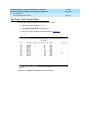
Check System Status for Each Cabinet
4-2
■
Check Circuit Pack Configuration
4-3
■
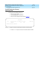
Test TDM Bus in PPN
4-4
■
Test Tone-Clock Circuit Packs
4-5
■
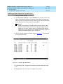
Test SPE Duplication Memory Shadowing Link
4-6
Issue 5
May 1998
DEFINITY Enterprise Communications Server Release 6
Installation and Test for Multi-Carrier Cabinets 555-230-112
Contents
Page v
Test Duplicated Switch Processing
Element Interchange
4-7
■
Test Expansion Interface Circuit Packs
4-8
■
Test TDM for each EPN
4-9
■
Test Tone-Clock for each EPN
4-10
■
Test Tone-Clock Interchange for each EPN
4-10
■
Test Expansion Interface Exchange for Each EPN
4-11
■
Check Circuit Pack Configuration Again
4-12
■
System Test Completion
4-12
■
LED Indicators
4-13
■
5
Install and Wire Telephones and
Other Equipment
5-1
■
Analog Station or 2-Wire Digital Station Example
5-5
■
Analog Tie Trunk Example
5-6
■
Digital Tie Trunk Example
5-7
■
DS1 Tie Trunk Example
5-8
■
Auxiliary Connector Outputs
5-10
■
Three-Pair and Four-Pair Modularity
5-13
■
Adjunct Power Connections
5-14
■
Attendant Console
5-16
■
26B1 Selector Console
5-16
■
Connect External Alarm Indicators
5-17
■
Connect Power Distribution Unit External Alarm Wires 5-19
■
Remote Network Interface
5-22
■
TN1654 DS1 Converter (Release 6r Only)
5-23
■
Off-Premises Station Wiring
5-30
■
Off-Premises or Out-of-Building Stations
5-30
■
Emergency Transfer Units and Associated Telephones 5-36
■
External Ringing
5-44
■
Queue Warning Indicator
5-44
■
1145B Power Supply
5-45
■
1151A Power Supply
5-54
■
BRI Terminating Resistor
5-57
■
Multi-point Adapters
5-61
■
Add Circuit Packs
5-64
■
List of Circuit Packs
5-65
Issue 5
May 1998
DEFINITY Enterprise Communications Server Release 6
Installation and Test for Multi-Carrier Cabinets 555-230-112
Contents
Page vi
6
■
Add the Fiber Optic Cable
5-70
■
Add CO, FX, WATS, and PCOL
5-85
■
Add DID Trunks
5-86
■
Add Tie Trunks
5-87
■
Add DS1 Tie and OPS
5-89
■
Add Code Calling Access
5-93
■
Add Speech Synthesis
5-93
■
Add Pooled Modem
5-93
■
Add External Modem to EPN
5-94
■
Add External Modem to PPN
5-95
■
Add External Modem to TN1648B
5-96
■
Add Multiple Announcement
5-106
■
Add ISDN — PRI
5-110
■
Add Packet Bus to R6si
5-113
■
Add CallVisor ASAI
5-117
■
Add ISDN—BRI
5-121
■
Add PRI Over PACCON to R6si
5-124
■
CAMA/E911 Installation
5-131
■
Connector and Cable Diagrams (Pinout Charts)
5-143
Test Telephones and Other Equipment
6-1
■
Make Test Calls
6-2
■
Test 302C Attendant Console
6-2
■
Test External Ringing
6-3
■
Test Queue Warning Indicator
6-3
■
Test Integrated Announcement
6-3
■
Test Music-on-Hold
6-4
■
Test Emergency Transfer
6-4
■
Test Remote Access Interface
6-4
■
Test Basic Rate Interface
6-5
■
Test Duplication Option Processing
Element Interchange
6-5
■
Test Terminating Trunk Transmission
6-6
■
Test Stratum 3 Clock
6-7
■
Perform Complete System Test
6-8
■
Activate and Test Alarm Origination Feature
6-9
Issue 5
May 1998
DEFINITY Enterprise Communications Server Release 6
Installation and Test for Multi-Carrier Cabinets 555-230-112
Contents
Page vii
A
B
Connecting Fiber Optic Cables
A-1
■
LASER Product
A-2
■
Fiber Optic Requirements
A-2
■
Optical Cross-Connect Hardware
A-6
■
Cleaning Fiber Optic Cables
A-16
■
Labels for Fiber Optic Cables
A-16
■
Making Changes at an LIU or Shelf
A-17
■
Routing Fiber Optic Cables
A-18
Option Switch Settings
B-1
■
External Modem Option Settings
B-2
■
Printer Option Settings
B-5
■
Call Detail Recording Option Settings
B-8
■
TN760D Tie Trunk Option Settings
B-10
■
TN464E/F Option Settings
B-12
C
Cable Ductwork
C-1
D
Connector and Cable Diagrams
D-1
E
References
E-1
■
Basic DEFINITY ECS Documents
E-1
■
Call Center Documents
E-5
■
Application-Specific Documents
E-6
■
Documents on CD-ROM
E-9
GL Glossary and Abbreviations
GL-1
IN
IN-1
Index
DEFINITY Enterprise Communications Server Release 6
Installation and Test for Multi-Carrier Cabinets 555-230-112
Issue 5
May 1998
About This Book
Page viii
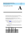
About This Book
This book provides procedures and information for installing and initially testing
the DEFINITY® Enterprise Communications Server Multi-Carrier Cabinets.
This document covers information related to DEFINITY ECS Release 6. For
details about changes for Release 6, refer to DEFINITY Enterprise
Communications Server Release 6.1, Change Description.
The following conventions describe the systems referred to in this book.
■
The word system, is a general term and includes references to the
DEFINITY Enterprise Communications Server
■
DEFINITY Systems are called: Release 5, Release 5r, Release 6, and
Release 6r
■
All occurrences of Release 5r, and Release 6r are called Release 6r
unless a specific configuration is required to differentiate between product
offerings
■
Information in this book is applicable for Release 5 through Release 6
unless otherwise specified
■
DEFINITY Enterprise Communications Server is abbreviated DEFINITY
ECS
This book describes installation and wiring including:
1. Placing and interconnecting the various cabinets and adjuncts.
2. Wiring from the telephone network interface to and including the 25-pair
cables that connect directly to the system.
3. The main equipment room main distribution frame and the associated
cabling to the system and/or 8-pin information outlets (modular wall jacks).
4. Testing of the completed installation.
DEFINITY Enterprise Communications Server Release 6
Installation and Test for Multi-Carrier Cabinets 555-230-112
Issue 5
May 1998
About This Book
Organization
Page ix
This issue replaces all previous issues of DEFINITY Communications System
Generic 1 and Generic 3 Installation and Test, 555-204-104.
NOTE:
This book is being modified for international translation. This means some
illustrations contain numbers instead of descriptive text. In the future, all
illustrations will contain numbers.
Organization
This book contains the following chapters:
Chapter 1, ‘‘Install and Connect Cabinets’’ — How to install the cabinets,
connect power, and connect the cabinets together.
Chapter 2, ‘‘Install Telecommunications Cabling’’ — How to install cabling
between the system and the Main Distribution Frame.
Chapter 3, ‘‘Install Management Terminal and Activate System’’ — How to install
the management terminal and how to activate and initialize the system.
Chapter 4, ‘‘Test the System’’ — How to initially test the system.
Chapter 5, ‘‘Install and Wire Telephones and Other Equipment’’— How to install
and wire telephones and other equipment to the system.
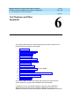
Chapter 6, ‘‘Test Telephones and Other Equipment’’ — How to test the
equipment installed in Chapter 5.
How to Comment on This Book
Lucent Technologies welcomes your feedback. Please fill out the reader
comment card at the front of this book and return it. Your comments are of great
value and help improve our documentation.
If the reader comment card is missing, fax your comments to 1-303-538-1741 or
to your Lucent Technologies representative, and mention this document’s name
and number, DEFINITY Enterprise Communication Server Release 6 Installation
and Test for Multi-Carrier Cabinets, 555-230-112.
DEFINITY Enterprise Communications Server Release 6
Installation and Test for Multi-Carrier Cabinets 555-230-112
About This Book
Related Books
Issue 5
May 1998
Page x
Related Books
The following books are useful for system-related information:
■
DEFINITY Enterprise Communications Server Release 6 System
Description Pocket Reference, 555-230-211
■
DEFINITY Enterprise Communications Server Release 6 Maintenance for
R6r, 555-230-126
■
DEFINITY Enterprise Communications Server Release 6 Maintenance for
R6vs/si, 555-230-127
■
AT&T Network and Data Connectivity Reference, 555-025-201
■
BCS Products Security Handbook, 555-025-600
■
DEFINITY Wireless Business System Users Guide, 555-232-105
■
DEFINITY Wireless Business System Installation and Test Guide,
555-232-102
■
DEFINITY Wireless Business Systems System Interface, 555-232-108
■
DEFINITY Enterprise Communications Server Release 6 Installation and
Test for Single-Carrier Cabinets, 555-230-894
■
DEFINITY Enterprise Communications Server Release 6 Administration
and Feature Description, 555-230-522
■
DEFINITY Enterprise Communications Server Release 6 Upgrades and
Additions for R6vs/si, 555-230-120
■
DEFINITY Enterprise Communications Server Release 6 Upgrades and
Additions for R6r, 555-230-121
■
Switch Administration for DEFINITY AUDIX, 585-300-509
How to Order Books
In addition to this book, other description, installation and test, maintenance, and
administration books are available. A complete list of DEFINITY books is
provided in the Business Communications System Publications Catalog ,
555-000-010.
This book and any other DEFINITY books can be ordered directly from the
Lucent Technologies Business Communications System Publications Fulfillment
Center at 1-317-322-6791 or toll free at 1-800-457-1235.
DEFINITY Enterprise Communications Server Release 6
Installation and Test for Multi-Carrier Cabinets 555-230-112
Issue 5
May 1998
About This Book
Trademarks
Page xi
Trademarks
This document contains references to the following Lucent Technologies
trademarked products:
■
ACCUNET®
■
AUDIX®
■
Callmaster®
■
CallVisor®
■
CONVERSANT®
■
DEFINITY®
■
FORUM™
■
LGX®
■
MEGACOM®
■
SYSTIMAX®
■
TRANSTALK™
The following products are trademarked by their appropriate vendor:
■
Audichron® is a registered trademark of Audichron Company
■
Music Mate® is a registered trademark of Harris Corporation
■
■
PagePac ® is a registered trademark of Harris Corporation, Dracon
Division
SHOCKWATCH ® is a registered trademark of Media Recovery,
Incorporated
■
Styrofoam® is a registered trademark of Styrofoam Corporation
■
TILTWATCH® is a registered trademark of Media Recovery, Incorporated
■
VELCRO® is a registered trademark of VELCRO U.S.A. Incorporated
■
Zone Mate® is a registered trademark of Harris Corporation
DEFINITY Enterprise Communications Server Release 6
Installation and Test for Multi-Carrier Cabinets 555-230-112
About This Book
Standards Compliance
Standards Compliance
The equipment presented in this book complies with the following (as
appropriate):
■
ITU-T (Formerly CCITT)
■
ECMA
■
ETSI
■
IPNS
■
DPNSS
■
National ISDN-1
■
National ISDN-2
■
ISO-9000
■
ANSI
■
FCC Part 15 and Part 68
■
EN55022
■
EN50081
■
EN50082
■
CISPR22
■
Australia AS3548 (AS/NZ3548)
■
Australia TS 001 (AS/NZS3260)
■
IEC 825
■
IEC 950
■
UL 1459
■
UL 1950
■
CSA C22.2 Number 225
Contact your Lucent Technologies representative for more information.
Issue 5
May 1998
Page xii
DEFINITY Enterprise Communications Server Release 6
Installation and Test for Multi-Carrier Cabinets 555-230-112
About This Book
LASER Product
Issue 5
May 1998
Page xiii
LASER Product
The DEFINITY ECS may contain a Class 1 LASER device if single-mode fiber
optic cable is connected to a remote Expansion Port Network (EPN). The LASER
device operates within the following parameters:
Power Output: -5 dBm
Wavelength: 1310 nm
Mode Field Diameter: 8.8 microns
CLASS 1 LASER PRODUCT
IEC 825 1993
! CAUTION:
Use of controls or adjustments or performance of procedures other than
those specified herein may result in hazardous radiation exposure.
Contact your Lucent Technologies representative for more information.
Electromagnetic Compatibility
Standards
This product complies with and conforms to the following:
■
Limits and Methods of Measurements of Radio Interference
Characteristics of Information Technology Equipment, EN55022
(CISPR22), 1993
■
EN50082-1, European Generic Immunity Standard
■
FCC Part 15
■
Australia AS3548
NOTE:
The system conforms to Class A (industrial) equipment. Voice terminals
meet Class B requirements.
■
Electrostatic Discharge (ESD) IEC 1000-4-2
■
Radiated radio frequency field IEC 1000-4-3
■
Electrical Fast Transient IEC 1000-4-4
■
Lightning effects IEC 1000-4-5
■
Conducted radio frequency IEC 1000-4-6
■
Mains frequency magnetic field IEC 1000-4-8
■
Low frequency mains disturbance
DEFINITY Enterprise Communications Server Release 6
Installation and Test for Multi-Carrier Cabinets 555-230-112
Issue 5
May 1998
About This Book
Electromagnetic Compatibility Standards
Page xiv
The system conforms to the following:
■
Electromagnetic compatibility General Immunity Standard, part 1;
residential, commercial, light industry, EN50082-1, CENELEC, 1991
■
Issue 1 (1984) and Issue 2 (1992), Electrostatic discharge immunity
requirements (EN55024, Part 2) IEC 1000-4-2
■
Radiated radio frequency field immunity requirements IEC 1000-4-3
■
Electrical fast transient/burst immunity requirements IEC 1000-4-4
European Union Standards
Lucent Technologies Business Communications Systems declares that the
DEFINITY equipment specified in this book bearing the Conformité Europeénne
(CE) mark conforms to the European Union Electromagnetic Compatibility
Directives.
The CE mark indicates conformance to the European Union Electromagnetic
Compatibility Directive (89/336/EEC) Low Voltage Directive (73/23/EEC) and
Telecommunication Terminal Equipment (TTE) Directive (91/263/EEC) and with
i-CTR3 Basic Rate Interface (BRI) and i-CTR4 Primary Rate Interface (PRI) as
applicable. The CE mark is applied to the following Release 6 products:
■
Global AC powered Multi-Carrier Cabinet (MCC)
■
DC powered Multi-Carrier Cabinet (MCC) with 25 Hz ring generator
■
AC powered Single-Carrier Cabinet (SCC) with 25 Hz ring generator
■
AC powered Compact Single-Carrier Cabinet (CSCC) with 25 Hz ring
generator
■
Enhanced DC Power System
■
Compact Modular Cabinet (CMC) with 25 Hz ring generator
Issue 5
May 1998
DEFINITY Enterprise Communications Server Release 6
Installation and Test for Multi-Carrier Cabinets 555-230-112
About This Book
Where to Call for Technical Support
Page xv
Where to Call for Technical Support
Use the following telephone numbers for the region in which the system is being
installed:
Telephone Number
Streamlined Implementation (for missing equipment)
1-800-772-5409
USA/Canada Technical Service Center
1-800-248-1234
Technical Service Center (INADS Database
Administration)
1-800-248-1111
Asia/Pacific Regional Support Center
65-872-8686
Western Europe/South Africa/Middle East
441-252-774-800
Business Communications Europe
441-252-391-789
Eastern/Central Europe
361-345-4334
ITAC
1-303-804-3777
Latin/Central America & Caribbean
1-303-804-3778
DEFINITY Helpline
1-800-225-7585
Lucent Technologies Toll Fraud Intervention
1-800-643-2353
Lucent Technologies Technical Service Center
1-800-242-2121
Lucent Technologies Corporate Security
1-800-822-9009
Anti-Static Protection
! CAUTION:
When handling circuit packs or any components of a DEFINITY System,
always wear an authorized wrist ground strap. Connect the strap to an
approved ground such as an unpainted metal surface on the DEFINITY
System.
Security Issues
To ensure the greatest security possible for customers, Lucent Technologies
offers services that can reduce toll-fraud liabilities. Contact your Lucent
Technologies representative for more security information.
Login security is an attribute of the DEFINITY ECS software. Existing passwords
expire 24 hours after installation.
DEFINITY Enterprise Communications Server Release 6
Installation and Test for Multi-Carrier Cabinets 555-230-112
About This Book
Federal Communications Commission Statement
Issue 5
May 1998
Page xvi
Federal Communications Commission
Statement
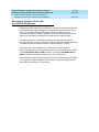
Part 68: Statement
Part 68: Answer-Supervision Signaling. Allowing this equipment to be operated in
a manner that does not provide proper answer-supervision signaling is in
violation of Part 68 rules. This equipment returns answer-supervision signals to
the public switched network when:
■
Answered by the called station
■
Answered by the attendant
■
Routed to a recorded announcement that can be administered by the CPE
user
This equipment returns answer-supervision signals on all DID calls forwarded
back to the public switched telephone network. Permissible exceptions are:
■
A call is unanswered
■
A busy tone is received
■
A reorder tone is received
Lucent Technologies attests that this registered equipment is capable of
providing users access to interstate providers of operator services through the
use of access codes. Modification of this equipment by call aggregators to block
access dialing codes is a violation of the Telephone Operator Consumers Act of
1990.
This equipment complies with Part 68 of the FCC Rules. On the rear of this
equipment is a label that contains, among other information, the FCC registration
number and ringer equivalence number (REN) for this equipment. If requested,
this information must be provided to the telephone company.
The REN is used to determine the quantity of devices which may be connected
to the telephone line. Excessive RENs on the telephone line may result in devices
not ringing in response to an incoming call. In most, but not all areas, the sum of
RENs should not exceed 5.0. To be certain of the number of devices that may be
connected to a line, as determined by the total RENs, contact the local telephone
company.
NOTE:
REN is not required for some types of analog or digital facilities.
Issue 5
May 1998
DEFINITY Enterprise Communications Server Release 6
Installation and Test for Multi-Carrier Cabinets 555-230-112
About This Book
Federal Communications Commission Statement
Page xvii
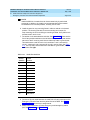
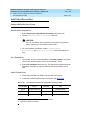
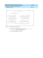
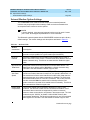
Means of Connection
Connection of this equipment to the telephone network is shown in the following
table (U.S. only).
Manufacturer’s Port Identifier
FIC Code
SOC/REN/
A.S. Code
Off/On Premises Station
OL13C
9.0F
RJ2GX, RJ21X,
RJ11C
DID Trunk
02RV2-T
0.0B
RJ2GX, RJ21X
CO Trunk
02GS2
0.3A
RJ21X
CO Trunk
02LS2
3.0A
RJ21X
Tie Trunk
TL31M
9.0F
RJ2GX
1.544 Digital Interface
04DU9-B,C
6.0F
RJ48C, RJ48M
1.544 Digital Interface
04DU9-BN,KN
6.0F
RJ48C, RJ48M
120A2 Channel Service Unit
04DU9-DN
6.0F
RJ48C
Network Jacks
If the terminal equipment (DEFINITY® System) causes harm to the telephone
network, the telephone company will notify you in advance that temporary
discontinuance of service may be required. But if advance notice is not practical,
the telephone company will notify the customer as soon as possible. Also, you
will be advised of your right to file a complaint with the FCC if you believe it is
necessary.
The telephone company may make changes in its facilities, equipment,
operations or procedures that could affect the operation of the equipment. If this
happens, the telephone company will provide advance notice in order for you to
make necessary modifications to maintain uninterrupted service.
If trouble is experienced with this equipment, for repair or warranty information,
please contact the Technical Service Center at 1-800-242-2121. If the equipment
is causing harm to the telephone network, the telephone company may request
that you disconnect the equipment until the problem is resolved.
It is recommended that repairs be performed by Lucent Technologies certified
technicians.
The equipment cannot be used on public coin phone service provided by the
telephone company. Connection to party line service is subject to state tariffs.
Contact the state public utility commission, public service commission or
corporation commission for information.
This equipment, if it uses a telephone receiver, is hearing aid compatible.
DEFINITY Enterprise Communications Server Release 6
Installation and Test for Multi-Carrier Cabinets 555-230-112
1
1
Install and Connect Cabinets
Unpack and Inspect Cabinets
Install and Connect Cabinets
Issue 5
May 1998
Page 1-1
1
This chapter discusses installation of Multi-Carrier Cabinets only. For information
on Single-Carrier Cabinets, refer to DEFINITY Enterprise Communications Server
Release 5 Installation and Test for Single-Carrier Cabinets.
Floor plans and equipment layouts for typical system installations are provided in
DEFINITY Enterprise Communications Server Release 6 System Description
Pocket Reference.
Unpack and Inspect Cabinets
Perform these steps for all cabinets.
! DANGER:
A cabinet may weigh as much as 800 lbs (363 kg) and may be top heavy.
Use extreme caution.
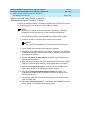
1. Check the status of the SHOCKWATCH and/or TILTWATCH indicators on
the container. If the container has been shaken or tilted beyond
specifications, the indicators are red, indicating potential damage. Report
any damage according to local shipping instructions.
! DANGER:
Take care to avoid injury while cutting and removing the 2 metal bands.
2. Unpack the cabinet and remove all packing material.
3. Move the cabinets into their proper positions.
4. Do not adjust the leveling feet at this time.
DEFINITY Enterprise Communications Server Release 6
Installation and Test for Multi-Carrier Cabinets 555-230-112
1
Install and Connect Cabinets
Check Customer’s Order
Issue 5
May 1998
Page 1-2
Unpack and Inspect Auxiliary Cabinet
The Auxiliary cabinet is normally positioned adjacent to the PPN cabinet or the
EPN cabinet, if provided.
1. Unpack the cabinets as outlined on the previous page.
2. Remove the lower rear panel from the Auxiliary cabinet. Install the lower
rear panel when the installation is completed.
Unpack and Inspect Stratum 3 Clock Cabinet
1. Check the status of the SHOCKWATCH and/or TILTWATCH indicators on
the cardboard container. If the container has been jarred or tilted beyond
specifications, the indicators are red, indicating possible damage.
2. Remove all packing material.
3. Remove front door and rear screw-on panels from the cabinet.
4. Inspect the cabinet for damage. Report any damage per local
instructions.
Check Customer’s Order
1. Check the customer’s order and the shipping packing lists to confirm all
equipment is present. If any equipment is missing, report the information
to your Lucent Technologies representative.
2. Ensure all circuit packs are fully inserted into the proper slots according to
the Customer Service Document (CSD). Report any discrepancies in
circuit pack type or quantity to your Lucent Technologies representative.
3. Check the system adjuncts for damage and report all damage according
to local shipping instructions.
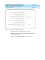
Correcting Shipping Errors
1. Red-tag all defective equipment and over-shipped equipment and return
per the nearest Material Stocking Location (MSL) instructions. For
international customers, contact your order service agent.
2. Direct all short-shipped reports to the nearest MSL. Contact the
appropriate location for specific instructions. For Streamlined
Implementation in the United States, call 1-800-772-5409.
DEFINITY Enterprise Communications Server Release 6
Installation and Test for Multi-Carrier Cabinets 555-230-112
1
Install and Connect Cabinets
Install System Cabinets
Issue 5
May 1998
Page 1-3
Install System Cabinets
Check the location of the AC power receptacles in the equipment room. The
receptacles must be on a separately fused circuit not controlled by a wall switch.
They must be located within 10 feet (3 m) of the cabinet and outside the Main
Distribution Frame (MDF) area.
Position the PPN Cabinet
1. If the system is supplied with cable ductwork, space the cabinets on 32
inch (81.3 cm) centers +-1/8 inch (0.3 cm), they must be level, and must
be square with respect to each other.
2. If the system is supplied with cable slack managers, place the cabinets far
enough from the connection field to lay down the 32 inch (81.3 cm) slack
managers and to provide a little extra room for the cables to access the
cable slack managers.
3. If earthquake protection is required, skip to ‘‘Earthquake Protection
Installation’’ on page 1-34.
4. If earthquake protection is not required, level the cabinets and adjust and
lock the cabinet stabilizing bolts to keep the cabinet from moving.
5. At the bottom of the cabinet, install hole plugs (provided with cabinet) in
the holes previously occupied by the 4 carriage bolts.
Position the EPN Cabinets
Each EPN cabinet is normally positioned adjacent to the PPN cabinet but may be
located remotely in a different room or a different building.
1. The procedure for installing an EPN cabinet is the same as for the PPN
cabinet.
2. If earthquake protection is required, skip to ‘‘Earthquake Protection
Installation’’ on page 1-34.
3. If earthquake protection is not required, level the cabinets and adjust and
lock the cabinet stabilizing bolts to keep the cabinets from moving.
NOTE:
To install a new EPN cabinet to an existing system, refer to DEFINTY
Enterprise Communications Server Release 6 Upgrades and
Additions for R6r.
DEFINITY Enterprise Communications Server Release 6
Installation and Test for Multi-Carrier Cabinets 555-230-112
1
Install and Connect Cabinets
Install System Cabinets
Issue 5
May 1998
Page 1-4
Position the Auxiliary Cabinet (Optional)
1. Position the Auxiliary cabinet next to the PPN cabinet (or EPN cabinet, if
installed). The location of equipment inside the Auxiliary cabinet is
specified in the Customer Service Document (CSD).
2. If earthquake protection is required, skip to ‘‘Earthquake Protection
Installation’’ on page 1-34. Return to this section when finished.
3. If earthquake protection is not required, level the cabinets and adjust and
lock the cabinet stabilizing bolts to keep the cabinet from moving.
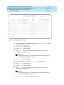
Install Auxiliary Cabinet Equipment
The Auxiliary cabinet allows for carrier, 23-inch (58.4 cm) rack, or panel
mounting of hardware. The following equipment is furnished with the cabinet.
■
■
■
■
Fuse panel — Distributes -48 VDC power to fused cabinet circuits
Power receptacle strip
receptacles
— Provides switched and unswitched 120 VAC
DC connector block — Required when Auxiliary cabinet is powered by an
external DC source
AC to DC power supply — Converts AC power provided by the AC power
strip switched outlet to the required DC voltage
1. Install equipment inside the cabinet as specified in the CSD. The following
optional equipment can be installed:
■
Audichron H9040 Wake-Up Announcement System
■
909A/B Universal Coupler
■
7400 Series Data Modules
■
Z77A Multiple Data Mounting
■
Fan Assembly — Requires 120 volt AC power
■
COMSPHERE 3000-series modems
■
■
External Channel Service Unit (CSU) — 1 is required for each T1
carrier link
PagePac Paging System — 3 models are available. All PagePac
models require 120 VAC power.
DEFINITY Enterprise Communications Server Release 6
Installation and Test for Multi-Carrier Cabinets 555-230-112
1
Install and Connect Cabinets
Install System Cabinets
■
Issue 5
May 1998
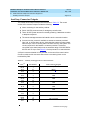
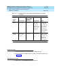
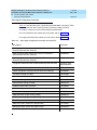
Page 1-5
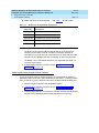
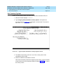
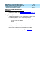
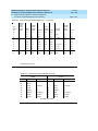
Model 15A Announcement System — See Table 1-1 for PEC codes.
Table 1-1.
Model 15A Announcement Equipment
PEC Code
Description
PEC 63240
1 chassis and 1 BLD1 circuit pack
PEC 63241
1 BLD1 circuit pack
PEC 63242
1 chassis and 1 BLD2 circuit pack
PEC 63243
1 BLD2 circuit pack
PEC 63246
1 remote record module
The BLD1 circuit pack provides 8 channels with up to 20 seconds of
recording time on each channel. The BLD2 circuit pack provides 8
channels with up to 40 seconds of recording time on each channel. Each
chassis can be populated with any combination of 2 BLD circuit packs.
The Model 15A Announcement System is FCC registered and does not
require a voice coupler.
2. If earthquake protection is required, skip to ‘‘Earthquake Protection
Installation’’ on page 1-34.
Install and Position Stratum 3 Clock Cabinet
Check the location of the AC power receptacle. The receptacle must be on a
separately fused circuit that is not controlled by a wall switch. It must be located
within 10 feet (3 m) of the cabinet and should be located outside the MDF area.
1. Position the clock cabinet in the designated location.
2. If earthquake protection is required, skip to ‘‘Earthquake Protection
Installation’’ on page 1-34.
3. If earthquake protection is not required, level the cabinets and adjust and
lock the cabinet stabilizing bolts to keep the cabinet from moving.
DEFINITY Enterprise Communications Server Release 6
Installation and Test for Multi-Carrier Cabinets 555-230-112
1
Install and Connect Cabinets
Connect AC Power and Ground
Issue 5
May 1998
Page 1-6
Connect AC Power and Ground
Power Requirements
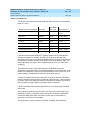
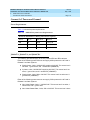
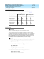
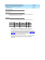
Table 1-2 shows the power requirements.
Table 1-2.
DEFINITY System Power Requirements
Maximum DEFINITY UL Rating Label Power Capacity
Vac In
Iac In
Max W In
BTU/Hr
208
24
3245
11071.26
240
21
3276
11177.71
120
40
3120
10645.44
J58890CE-1, J58890CE-2, and J58890CH-1
The following procedures apply to the AC-powered PPN and EPN cabinets.
Either of the following power sources can supply 60 Hz power to the AC load in
Release 5 and later systems:
■
Single-phase, 4-wire, 120/240 VAC supplying 240 VAC. This source has 2
hot wires, 1 ground wire, and 1 neutral wire (J58890CE).
■
3-phase, 4-wire, 120/208 VAC supplying 208 VAC. This source has 2 hot
wires, 1 ground wire, and 1 neutral wire (J58890CE).
■
Single-phase, 3-wire, 208 or 240 VAC. This source has 2 hot wires and 1
ground wire (J58890CH).
Either of the following power sources can supply 50 Hz power to the AC load in
Release 5 and later systems:
■
Non-United States 4-wire, Y, 220/380 VAC. This source has 3 hot wires, 1
neutral wire, and 1 ground wire.
■
Non-United States Delta, 3-wire, 220 or 240 VAC. This source has 3 wires.
Issue 5
May 1998
DEFINITY Enterprise Communications Server Release 6
Installation and Test for Multi-Carrier Cabinets 555-230-112
1
Install and Connect Cabinets
Connect AC Power and Ground
Page 1-7
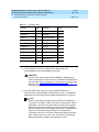
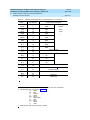
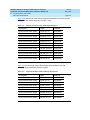
Table 1-3 describes the power sources and required AC input power.
Table 1-3.
AC Power Sources and Plug Type
Power Distribution
Unit
Power Sources
Power Input
AC power distribution
(J58890CE-1 and
J58890CE-2)
Multi-Carrier Cabinet
Single phase 120 VAC
with neutral
120 VAC, 60 Hz NEMA
5-50R
Single phase 240 VAC
with neutral, or single
phase of 3-phase, 208
VAC with neutral
208/240 VAC, 60 Hz NEMA
L14-30R
AC power distribution
(J58890CH-1)
Multi-Carrier Cabinet
Single Phase 176-264
VAC
200-240 Volts, 50-60 Hz
NEMA L6-30R. Installations
outside the United States
require a receptacle
suitable for use in the
country of installation.
NOTE:
The type of power required is shown on the cabinet’s rear door.
DEFINITY Enterprise Communications Server Release 6
Installation and Test for Multi-Carrier Cabinets 555-230-112
1
Install and Connect Cabinets
Connect AC Power and Ground
Issue 5
May 1998
Page 1-8
! CAUTION:
The equipment room AC power and ground wiring must be performed by a
qualified electrician. Refer to DEFINITY Enterprise Communications Server
Release 6 System Description Pocket Reference, for site requirement
information.
! CAUTION:
The power circuit must be dedicated to the system and must not be shared
with other equipment and must not be controlled by a wall switch. The AC
receptacle should not be located under the MDF.
! CAUTION:
System grounding must comply with the general rules for grounding
contained in Article 250 of the National Electrical Code (NEC), National Fire
Protection Agency (NFPA) 70, or the applicable electric code in the country
containing the equipment. For more information, refer to ‘‘Approved
Grounds’’ on page 1-23.
Connect Ground to AC-Powered System
(J58890CE)
Grounding is relatively simple for an AC-powered system. Basically, the cabinets
connect to the single-point ground terminal block located at either the AC load
center or to a separate single-point ground block wired to the AC load center (or
optional AC protector cabinet).
■
The approved ground wire must be a green (or green with yellow stripe), 6
AWG (#40) (16 mm2), copper, stranded wire.
■
Bond all approved grounds at the single-point ground to form a single
grounding electrode system.
AC Load Center is 50 Feet (15.2 m) or Less from
Cabinet
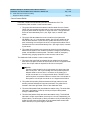
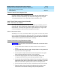
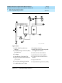
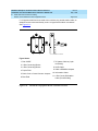
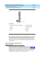
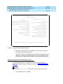
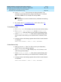
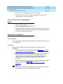
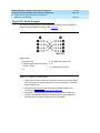
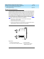
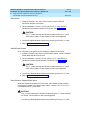
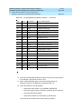
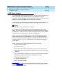
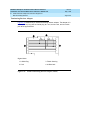
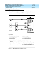
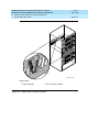
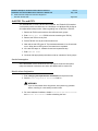
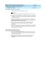
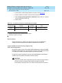
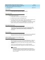
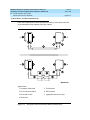
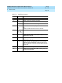
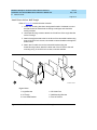
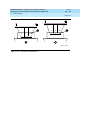
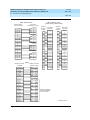
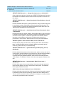
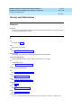
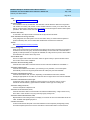
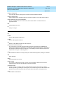
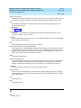
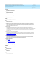
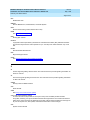
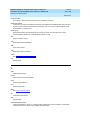
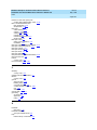
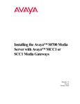
1. At the bottom rear of the PPN cabinet, connect a 6 AWG (#40) (16 mm 2)
CABINET GROUND wire to the cabinet ground terminal block. See Figure
1-1.
2. Route the CABINET GROUND wire to the single-point ground block at the
AC load center and connect.
3. At the bottom rear of the first EPN cabinet (if provided), connect a 6 AWG
(#40) (16 mm2) CABINET GROUND wire to the cabinet ground terminal
block.
4. Route the CABINET GROUND wire to the single-point ground block at the
AC load center and connect.
Issue 5
May 1998
DEFINITY Enterprise Communications Server Release 6
Installation and Test for Multi-Carrier Cabinets 555-230-112
1
Install and Connect Cabinets
Connect AC Power and Ground
Page 1-9
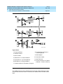
NOTE:
If the EPN cabinet is located remote from the PPN cabinet (in a
separate room or building), connect the CABINET GROUND wire to
an approved ground.
7
3
3
3
5
6
1
2
4
2
4
4
widmgrnd LJK 092697
Figure Notes
1. PPN Cabinet
2. EPN Cabinet (if Installed)
5. AC Load Center
Single-Point Ground
3. 6 AWG (#40) (16 mm2) CABINET GROUND
Wire
6. Less than 50 Wire Feet
(15.2 m)
4. Cabinet Ground Terminal Block
7. 10 AWG (#25) (6 mm2)
Ground Wire to CBC
Figure 1-1.
Typical Cabinet Ground Location
5. Repeat connecting each EPN cabinet to the single-point ground block.
DEFINITY Enterprise Communications Server Release 6
Installation and Test for Multi-Carrier Cabinets 555-230-112
1
Install and Connect Cabinets
Connect AC Power and Ground
Issue 5
May 1998
Page 1-10
6. At the AC load center, connect a 10 AWG (#25) (6 mm2) wire to the
single-point ground block. This ground wire will later be tie-wrapped to the
trunk cables and connected to the Coupled Bonding Conductor (CBC)
ground block at the MDF.
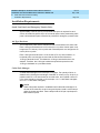
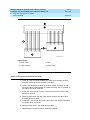
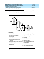
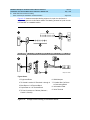
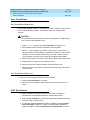
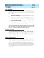
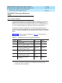
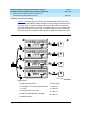
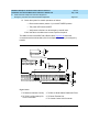
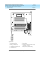
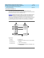
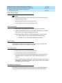
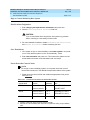
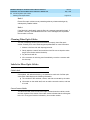
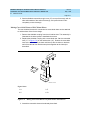
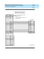
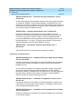
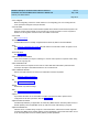
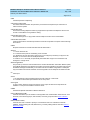
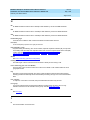
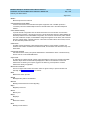
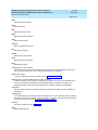
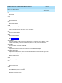
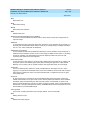
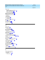
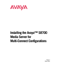
AC Load Center is More Than 50 Feet (15.2 m)
from Cabinet
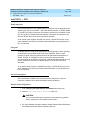
1. Mount the single-point ground block to any surface between the MCC
cabinets and the AC load center single-point ground. The single-point
ground block must be mounted to a non-metallic surface.
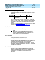
2. At the bottom rear of the PPN cabinet, connect a 6 AWG (#40) (16 mm 2)
CABINET GROUND wire to the cabinet ground block. See Figure 1-2.
3. Route the wire to the single-point ground block and connect.
4. At the first EPN cabinet (if provided), connect a 6 AWG (#40) (16 mm2)
CABINET GROUND wire to the cabinet ground terminal block.
5. Route the CABINET GROUND wire to the single-point ground block and
connect.
NOTE:
If the EPN cabinet is located remote from the PPN cabinet (in a
separate room or building), route the EPN CABINET GROUND wire
to an approved ground.
6. Repeat connecting each EPN cabinet to the single-point ground block.
7. Connect a 6 AWG (#40) (16 mm2) ground wire to an unused terminal on
the single-point ground block.
8. Route the ground wire to the AC load center ground and connect.
Issue 5
May 1998
DEFINITY Enterprise Communications Server Release 6
Installation and Test for Multi-Carrier Cabinets 555-230-112
1
Install and Connect Cabinets
Connect AC Power and Ground
Page 1-11
5
6
4
7
3
1
3
2
8
3
2
8
8
widfspgb KLC 100297
Figure Notes
1. PPN Cabinet
5. 6 AWG (#40) (16 mm2) Ground Wire
2. EPN Cabinet (if Installed)
6. AC Load Center Single-Point Ground
3. 6 AWG (#40) (16 mm2) CABINET
GROUND Wire
7. Over 50 Feet (15.2 m)
8. Cabinet Ground Terminal Block
4. Single-Point Ground Block
Figure 1-2.
Typical Cabinet Grounding Wiring Diagram
DEFINITY Enterprise Communications Server Release 6
Installation and Test for Multi-Carrier Cabinets 555-230-112
1
Install and Connect Cabinets
Connect AC Power and Ground
Issue 5
May 1998
Page 1-12
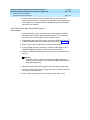
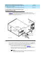
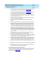
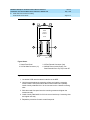
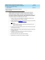
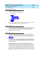
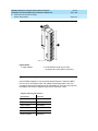
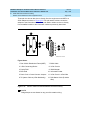
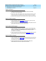
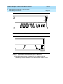
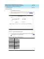
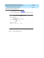
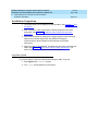
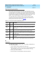
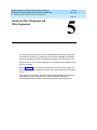
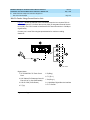
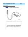
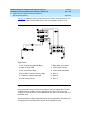
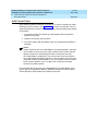
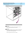
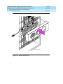
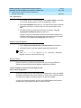
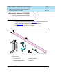
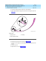
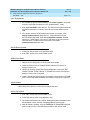
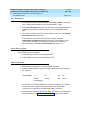
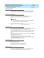
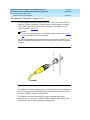
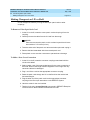
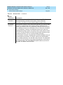
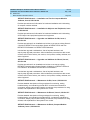
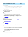
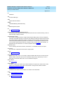
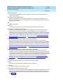
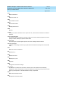
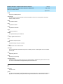
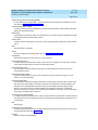
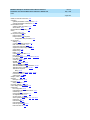
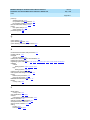
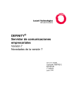
Connect Battery Leads (J58890CH-1)
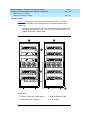
Figure 1-3 shows a typical optional small battery holdover assembly. These
assemblies may ship with the battery leads disconnected to prevent the batteries
from discharging.
1. Plug the battery connector into the -48 VDC Batteries connector on the
rear of the J58890CH-1 Power Distribution Unit.
Battery
connector
psdfbatb RPY 061797
Figure 1-3.
Typical Small Battery Assembly
! CAUTION:
Power is present in the cabinet even if the AC power cable is unplugged.
Turn off the main circuit breaker on the front of the power distribution unit
when procedures require ALL power to be removed from the cabinet.
Issue 5
May 1998
DEFINITY Enterprise Communications Server Release 6
Installation and Test for Multi-Carrier Cabinets 555-230-112
1
Install and Connect Cabinets
Connect AC Power and Ground
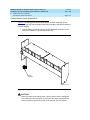
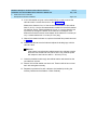
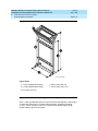
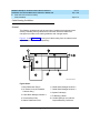
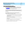
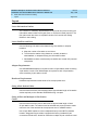
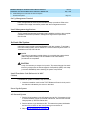
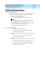
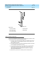
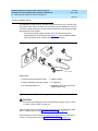
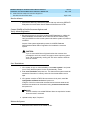
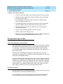
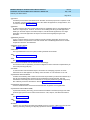
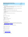
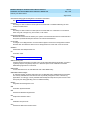
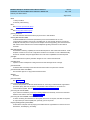
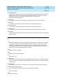
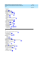
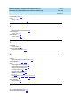
Page 1-13
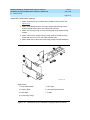
Figure Notes
1. Connect small battery holdover cable (or
temperature sensor cable from large battery
cabinet) to J20
2. Carrier Circuit Breakers
3. Ground Terminal Block
4. Connect large battery holdover cable here
Figure 1-4.
7. 1/0 AWG (50 mm2) 50 feet
(15.2 m) cable to large
battery cabinet. For
cables greater than 50
feet (15.2 m), contact your
Lucent Technologies
representative.
5. -48 VDC Return - 1/0 AWG (50 mm2) cable
8. Ground Terminal Block
6. -48 VDC - 1/0 AWG (50 mm2) cable
9. To AC load center or
approved single-point
ground block
Power Distribution Unit (J58890CH)
2. Be sure the main power to the power distribution unit is OFF.
3. At the power distribution unit, set all carrier circuit breakers OFF.
Small Battery Holdover
1. Connect the small battery holdover cable to J20. See Figure 1-4.
DEFINITY Enterprise Communications Server Release 6
Installation and Test for Multi-Carrier Cabinets 555-230-112
1
Install and Connect Cabinets
Connect AC Power and Ground
Issue 5
May 1998
Page 1-14
Large Battery Holdover
When using large battery holdover, 1 battery cabinet is required for every system
cabinet requiring holdover. The 24-cell battery cabinet must have a float voltage
of 54.2 VDC.
1. Connect the -48 VDC cable to the large battery connector. See Figure 1-4.
2. Connect the -48 VDC RETURN cable to the ground terminal block.
3. Connect the temperature sensor cable, from the battery cabinet, to J20.
NOTE:
An adapter cable may be required when connecting the temperature
sensor cable to the J58890CH unit. See Table 1-4.
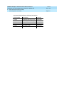
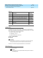
Table 1-4.
Temperature Sensor Cable Adapter Cables
H600-476 Adapter Cable
Usage
Group 1 (G1)
24-cell customer-provided battery
Group 3 (G3) (included
with battery cabinet)
24-cell Lucent Technologies battery
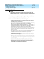
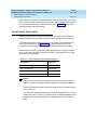
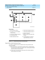
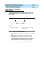
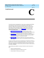
Connect Shorting Cable to J58890CE-2
! CAUTION:
For a cabinet with a battery charger, read the caution label on the 397C
battery charger before disconnecting batteries.
Some cabinets contain a J58890CE-2 AC Power Distribution Unit without an
optional battery charger. Install the shorting cable only when a battery charger is
not installed.
DEFINITY Enterprise Communications Server Release 6
Installation and Test for Multi-Carrier Cabinets 555-230-112
1
Install and Connect Cabinets
Connect AC Power and Ground
Issue 5
May 1998
Page 1-15
Figure Notes
1. Shorting Cable (H600-442-G1) (If
Battery Charger is Not Installed)
Figure 1-5.
2. J11
Shorting Cable Installation
1. Set the circuit breakers on the power distribution unit OFF. See Figure 1-5.
2. At the rear of the cabinet, insert the shorting cable (H600-442-G1) into
J11. The cable is keyed so it can fit only 1 way.
Connect AC Power
1. Set the main circuit breakers on the power distribution unit OFF.
2. Connect cabinet AC line cords to the AC power receptacles.
3. Do not power up the system at this time.
Issue 5
May 1998
DEFINITY Enterprise Communications Server Release 6
Installation and Test for Multi-Carrier Cabinets 555-230-112
1
Install and Connect Cabinets
Connect DC Power and Ground
Page 1-16
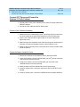
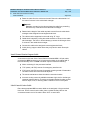
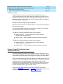
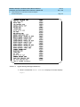
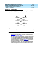
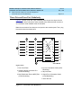
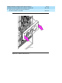
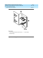
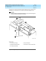
Connect DC Power and Ground
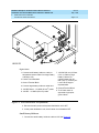
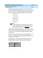
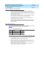
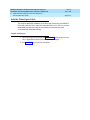
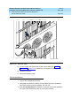
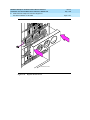
Power Distribution Unit (J58890CH-1 Only)
Rectifier Modules and Battery Interface Unit
Each rectifier module operates as an integral part of a complete power system
with battery backup. The modules operate in a redundant, high reliability mode to
provide -48 VDC at 850 Watts to a common power bus.
The Battery Interface Unit (BIU) controls the rectifier modules, manages the
batteries, and reports the status of system power. The BIU provides the Remote
Power Off (RPO) option and battery alarm interfaces for internal and external
alarms.
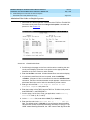
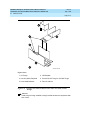
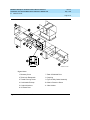
Figure Notes
1. Install Battery Interface Unit into Slot 1
4. Test Points
2. Install Rectifier Modules into Slots 2-5
5. Main Circuit Breakers
3. Rectifier Module 3 (in Slot 4)
Figure 1-6.
Rectifier Module Installation
Issue 5
May 1998
DEFINITY Enterprise Communications Server Release 6
Installation and Test for Multi-Carrier Cabinets 555-230-112
1
Install and Connect Cabinets
Connect DC Power and Ground
Page 1-17
1. Install the BU3200A Battery Interface Unit (comcode 107781502) in the
first slot of the power distribution unit. See Figure 1-6.
NOTE:
The BIU and the rectifier modules are keyed and can only install 1
way.
2. Install the first 2 RM0850HA100 Rectifier Modules (comcode 107793796)
into the second and third slots of the power distribution unit.
3. If 2 to 3 carriers are installed in the system, install a third rectifier module
(N+1).
4. If 4 to 5 carriers are installed in the system, install a fourth rectifier module.
5. The fifth rectifier module slot is reserved for future system growth.
Connect Power
1. Have a qualified electrician connect and route wires from the AC load
center to the dedicated electrical outlet for the power distribution unit.
Connect PPN Cabinet Ground
1. Connect 1 end of a 10 AWG (#25) (6 mm2) wire to the ground terminal
block on the rear of the cabinet. See Figure 1-4.
2. Route the wire to the Coupled Bonding Conductor (CBC), or to an
approved ground, and connect.
3. Connect 1 end of a 6 AWG (#40) (16 mm 2) CABINET GROUND wire to the
ground terminal block at the rear of the cabinet.
4. Route the CABINET GROUND wire to the AC load center single-point
ground block and connect.
Connect EPN Cabinet Ground(s)
1. Connect 1 end of a 6 AWG (#40) (16 mm 2) CABINET GROUND wire to the
ground terminal block at the bottom rear of the EPN cabinet. See Figure
1-2.
2. Route the CABINET GROUND wire to the AC load center single-point
ground and connect.
3. Connect each remaining EPN cabinet to the AC load center single-point
ground.
DEFINITY Enterprise Communications Server Release 6
Installation and Test for Multi-Carrier Cabinets 555-230-112
1
Install and Connect Cabinets
Connect DC Power and Ground
Issue 5
May 1998
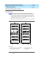
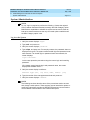
Page 1-18
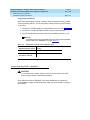
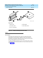
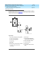
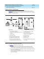
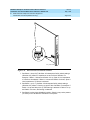
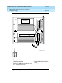
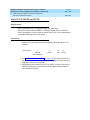
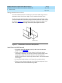
DC Power and Ground (J58890CF Only)
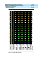
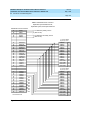
Figure 1-7 shows a typical power and ground layout for a DC-powered cabinet.
The size of the wire required for the -48 volt DC and -48 volt return must ensure
the -48 volt DC supplied by the battery plant is maintained between -42.5 and
-54.2 volts DC at all times for proper operation and to prevent hardware damage.
This procedure applies to both PPN and EPN cabinets.
Figure 1-7.
Typical Power and Ground for a DC-Powered Cabinet
DEFINITY Enterprise Communications Server Release 6
Installation and Test for Multi-Carrier Cabinets 555-230-112
1
Install and Connect Cabinets
Connect DC Power and Ground
Issue 5
May 1998
Page 1-19
Connect DC Power and Ground
The grounding methods for the DC-powered system are more complex than that
of an AC-powered system. The following installation procedures refer to Figure
1-7. The numbers 1-8 in Figure 1-7 match the following subsections 1-8. Other
figures may be referenced as required.
! CAUTION:
Grounding of the system shall comply with the general rules for grounding
contained in Article 250 of the National Electrical Code, NFPA 70. For more
information, refer to ‘‘Approved Grounds’’ on page 1-23.
1. Install Coupled Bonding Conductor Wires
This is a conductor that connects to the single-point ground block and run
adjacent to pairs in an associated cable. The mutual coupling between the CBC
and the pairs reduces potential differences in terminating equipment. The
conductor consists of a 10 AWG (#25) (6 mm 2) wire terminated at the CBC
ground terminal bar at the Main Distribution Frame (MDF).
1. At the DC Power Cabinet, connect a 10 AWG (#25) (6 mm2) ground wire to
the Ground Discharge Bar. See Figure 1-7.
2. Route the 10 AWG (#25) (6 mm2) ground wire to the CBC ground terminal
bar at the MDF. Be sure a minimum of 12 inches (30.5 cm) spacing is
maintained between the CBC and other power and ground leads.
3. Tie wrap the ground wire to the inside wiring cable.
NOTE:
The ground wires are connected to the CBC as instructed in Chapter 2,
‘‘Install Telecommunications Cabling’’.
2. Connect DC Battery and Power Cabinet
Grounds
1. Measure and cut a 6 AWG (#40) (16 mm2) wire (comcode 846110971)
long enough to reach between the ground connection terminal in the DC
Battery Cabinet and the Ground Discharge Bar in the DC Power Cabinet.
See Figure 1-7.
2. Crimp terminal lugs on each end of the wire. Terminal lugs are furnished
as part of D-181895, Kit of Parts (comcode 105434559).
3. At the DC Power Cabinet, connect the wire to the Ground Discharge Bar.
4. Route the wire through 1 of the holes in the side of the cabinets and
terminate it on the Ground Connection Terminal in the DC Battery Cabinet.
DEFINITY Enterprise Communications Server Release 6
Installation and Test for Multi-Carrier Cabinets 555-230-112
1
Install and Connect Cabinets
Connect DC Power and Ground
Issue 5
May 1998
Page 1-20
3. DC Power Cabinet Approved Ground
1. At the DC Power Cabinet, connect a 1 AWG (#70) (44 mm 2) ground wire to
the Ground Discharge Bar. See Figure 1-7.
2. Route the ground wire out of the cabinet and terminate it on the approved
ground. The approved ground must be identified with a grounding tag
(FORM 15657NR or equivalent). See ‘‘Approved Grounds’’ on page 1-23.
4. Connect Main AC Supply to DC Power Cabinet
1. Have a qualified electrician connect AC power leads to the rectifiers in the
DC Power Cabinet. Each rectifier should have its own branch circuit.
Terminate the leads on the AC INPUT terminal block of each rectifier.
2. Ensure the associated circuit breakers at the AC power panel are OFF.
5. Connect Ground Wires for DC-Powered
Systems
! CAUTION:
Do not connect any ground wires from an EPN cabinet to another EPN
cabinet or to a PPN cabinet. All ground wires must be terminated at the
single-point ground block at the main AC supply (AC mains).
1. Connect a 6 AWG (#40) (16 mm2) wire to the PPN cabinet ground terminal
block.
2. Route the wire to the AC mains single-point ground block and connect.
3. Connect a 6 AWG (#40) (16 mm 2) wire to each EPN’s cabinet ground
terminal block.
4. Route the wire(s) to the AC mains single-point ground block and connect.
6. Turn Circuit Breakers Off
The main circuit breaker on a DC-powered PPN/EPN cabinet is located on the
front of the power distribution unit. The circuit breakers on the rear of the power
distribution unit control the individual carriers. See Figure 1-4 for the location of
the carrier breakers.
1. Set the main circuit breaker to OFF.
2. Set the carrier circuit breakers to OFF.
DEFINITY Enterprise Communications Server Release 6
Installation and Test for Multi-Carrier Cabinets 555-230-112
1
Install and Connect Cabinets
Connect DC Power and Ground
Issue 5
May 1998
Page 1-21
7. Connect DC Power to PPN and EPN Cabinets
1. Be sure the main circuit breaker is OFF.
2. Measure and cut a piece of 6 AWG (#40) (16 mm2) wire long enough to
reach from the DC Power Cabinet to the PPN cabinet.
3. At the DC Power Cabinet, connect the -48 volt DC wire to the DC OUTPUT
circuit breaker. See Figure 1-7. Connect the -48 volt RTN (return) wire to
the ground discharge bar.
4. Route the wires out of the cabinet, through the hole in the lower rear cover,
and to the PPN cabinet.
5. Connect the -48 volt DC wire to the -48VDC terminal on the J58890CF
Power Distribution Unit.
6. Connect the -48 volt RTN wire to the -48RTN terminal on the J58890CF
Power Distribution Unit terminal block.
7. Repeat Steps 2 through 6 for each EPN and Auxiliary cabinet in the
system.
8. Connect DC Battery Cabinet to DC Power
Cabinet
! CAUTION:
When using battery backup, each cabinet in the system must have a
dedicated battery backup. The battery backup power cannot be shared
between cabinets.
1. Set the main circuit breaker on the DC Battery Cabinet and the DC Power
Cabinet to OFF.
2. Measure and cut a 6 AWG (#40) (16 mm2) wire long enough to reach from
the DC Battery Cabinet’s -48 Volt DC terminal to a DC OUTPUT circuit
breaker on the DC Power Cabinet.
3. At the DC Battery Cabinet, connect the -48 volt DC wire to the -48 VDC
connector. Connect the -48 volt RTN wire to the ground connection
terminal.
4. Route the wires out of the cabinet through the hole in the lower rear cover
and to the DC Power Cabinet.
5. At the DC Power Cabinet, terminate the -48 volt DC wire on a DC OUTPUT
circuit breaker. Terminate the -48 volt RTN (return) wire on the ground
discharge bar.
Issue 5
May 1998
DEFINITY Enterprise Communications Server Release 6
Installation and Test for Multi-Carrier Cabinets 555-230-112
1
Install and Connect Cabinets
Connect DC Power and Ground
Page 1-22
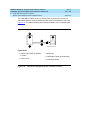
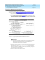
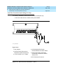
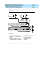
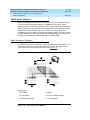
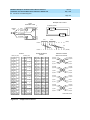
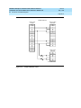
Mixed AC/DC Power and Ground
Figure 1-8 shows a power and ground layout for a mixed AC/DC-powered
cabinet configuration in the same equipment room with the PPN being DC
powered and the EPN being AC powered. If a second EPN is part of the system,
use the same basic connections shown in Figure 1-8.
1/0 AWG (50 mm2) up
to 50 feet (15.2 m) or
engineered for less than 0.5
voltage drop per conductor
Approved
ground
To
AC power
source
PPN
cabinet
Ground
discharge
bar
75A
EPN
cabinet
AC power cord
-48V
System
single-point
ground
-48V RTN
-48V
AC powerdistribution
unit
DC power supply
Cabinet Ground Block
To CBC terminal
block at MDF
Coupled Bonding Conductor
Figure 1-8.
cydfacdc RPY 021798
Typical Power and Ground for a Mixed AC/DC-Powered Cabinet
DEFINITY Enterprise Communications Server Release 6
Installation and Test for Multi-Carrier Cabinets 555-230-112
1
Install and Connect Cabinets
Approved Grounds
Issue 5
May 1998
Page 1-23
Approved Grounds
An approved ground is the closest acceptable medium for grounding the
building entrance protector, entrance cable shield, or single-point ground of
electronic telephony equipment. If more than 1 type of approved ground is
available on the premises, the grounds must be bonded together as required in
Section 250-81 of the National Electrical Code.
Grounded Building Steel — The metal frame of the building where it is
effectively grounded by 1 of the following grounds: acceptable metallic water
pipe, concrete encased ground, or a ground ring.
Acceptable Water Pipe — A metal underground water pipe, at least 1/2-inch
(1.3 cm) in diameter, in direct contact with the earth for at least 10 feet (3 m). The
pipe must be electrically continuous (or made electrically continuous by bonding
around insulated joints, plastic pipe, or plastic water meters) to the point where
the protector ground wire connects. A metallic underground water pipe must be
supplemented by the metal frame of the building, a concrete encased ground, or
a ground ring. If these grounds are not available, the water pipe ground can be
supplemented by 1 of the following types of grounds:
■
■
■
Other local metal underground systems or structures — Local
underground structures such as tanks and piping systems
Rod and pipe electrodes — A 5/8-inch (1.6 cm) solid rod or 3/4-inch (2
cm) conduit or pipe electrode driven to a minimum depth of 8 feet (2.4 m).
Plate electrodes — Must have a minimum of 2 square feet
(0.185 square m) of metallic surface exposed to the exterior soil
Concrete Encased Ground — An electrode encased by at least 2 inches
(5.1 cm) of concrete and located within and near the bottom of a concrete
foundation or footing in direct contact with the earth. The electrode must be at
least 20 feet (6.1 m) of 1 or more steel reinforcing bars or rods 1/2-inch (1.3 cm)
in diameter, or at least 20 feet (6.1 m) of bare, solid copper, 4 AWG (26 mm2)
wire.
Ground Ring — A buried ground that encircles a building or structure at a depth
of at least 2.5 feet (0.76 m) below the earth’s surface. The ground ring must be at
least 20 feet (6.1 m) of 2 AWG (35 mm2), bare, copper wire.
DEFINITY Enterprise Communications Server Release 6
Installation and Test for Multi-Carrier Cabinets 555-230-112
1
Install and Connect Cabinets
Approved Grounds
Issue 5
May 1998
Page 1-24
Approved Floor Grounds
Approved floor grounds are those grounds on each floor of a high-rise building
suitable for connection to the ground terminal in the riser closet and to the
cabinet equipment single-point ground terminal. Approved floor grounds may
include the following:
■
Building steel
■
The grounding conductor for the secondary side of the power transformer
feeding the floor
■
Metallic water pipes
■
Power feed metallic conduit supplying panel boards on the floor
■
A grounding point specifically provided in the building for the purpose
! WARNING:
If the approved ground or approved floor ground can only be accessed
inside a dedicated power equipment room, then connections to this ground
should be made by a licensed electrician.
Issue 5
May 1998
DEFINITY Enterprise Communications Server Release 6
Installation and Test for Multi-Carrier Cabinets 555-230-112
1
Install and Connect Cabinets
Connect Remote Power Off Cable and External Alarm Cable
Page 1-25
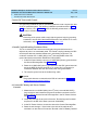
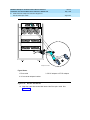
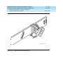
Connect Remote Power Off Cable and
External Alarm Cable
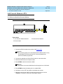
Figure 1-9 shows the location of the Remote Power Off (RPO) cable. The
opposite end of the cable connects to the Emergency Power Off (EPO) switch
located outside of the equipment room.
Carrier
circuit
breakers
Connect RPO
cable here (J21)
Connect external
alarm cable here
(J18)
Pin 6 (-RPO)
Pin 2 (+RPO)
psdf002 CJL 081596
Figure 1-9.
External
alarm cable
Remote Power Off Cable Connections — Part 1
Even though the equipment room EPO switch disconnects main AC power to the
equipment room, it cannot disconnect the battery power from the J58890CH. An
auxiliary set of contacts inside the EPO are used for this function.
1. Plug the RPO cable into the connector shown in Figure 1-9.
2. Route the opposite end of the wires to the EPO switch. The opposite end
of the RPO cable connects to the internal relay.
NOTE:
The EPO switch and the auxiliary contacts (inside the EPO switch
assembly) are customer-provided.
Issue 5
May 1998
DEFINITY Enterprise Communications Server Release 6
Installation and Test for Multi-Carrier Cabinets 555-230-112
1
Install and Connect Cabinets
Connect Remote Power Off Cable and External Alarm Cable
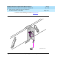
Page 1-26
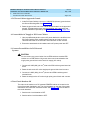
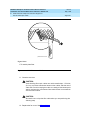
! CAUTION:
The auxiliary contacts inside the EPO switch assembly must close when the
switch is pressed. This contact closure energizes the relay inside the power
distribution unit, causing the connection to the battery holdover assembly to
open.
Figure 1-10 shows the cabling from the auxiliary contacts inside the EPO switch
assembly and how they connect to the internal relay.
Power Distribution Unit
TB3
Relay
(K1)
Battery
Cabinet
Ground
Terminal
Bar
Figure 1-10.
To Carriers
A to E
RPO Cable
TB1
Auxiliary Contacts
in EPO Switch
Shunt
2 6
0026_3 RBP 080196
Remote Power Off Cable Connections — Part 2
1. Connect the RPO wires to the auxiliary contacts on the EPO switch. See
Figure 1-10.
NOTE:
The EPO switch and the auxiliary contacts for the RPO connection
are customer-supplied.
DEFINITY Enterprise Communications Server Release 6
Installation and Test for Multi-Carrier Cabinets 555-230-112
1
Install and Connect Cabinets
Connect External Alarm Cable
Issue 5
May 1998
Page 1-27
Connect External Alarm Cable
1. Plug the external alarm cable into the connector shown in Figure 1-9.
2. Route the opposite end of the cable to the MDF. The alarm cable is
connected to the MDF in Chapter 5, ‘‘Install and Wire Telephones and
Other Equipment’’.
Connect AC Power to Stratum 3 Clock
Cabinet
The clock cabinet requires a 120 VAC, 15 Amp receptacle. The green wire
ground provided by the receptacle is sufficient. The clock cabinet does not
require a ground connection back to the single-point ground.
Check Commercial Power and Connect AC Power
Before powering up the system, check the AC power using a KS-20599 digital
voltmeter (DVM) (or equivalent).
1. Set the DVM to the 250 volt range.
2. Carefully measure the voltage between the hot and neutral side of the
receptacle. The neutral wire is white, the hot wire is black.
3. Verify the meter reads 106 to 128 VAC. If not, have a qualified electrician
correct the problem.
4. Measure the voltage between the neutral and ground side of the
receptacle. The ground wire is green.
5. Verify the meter reads 0 VAC. If not, have a qualified electrician correct the
problem.
6. Set all cabinet power modules OFF. Plug the AC power cable into the
receptacle.
DEFINITY Enterprise Communications Server Release 6
Installation and Test for Multi-Carrier Cabinets 555-230-112
Issue 5
May 1998
Install and Connect Cabinets
Connect DC Power and Ground to Stratum 3 Clock Cabinet
Page 1-28
1
Connect DC Power and Ground to
Stratum 3 Clock Cabinet
1. Provide power for the clock cabinet from the same DC power plant as the
DEFINITY System.
2. Ground the clock cabinet to the DC power plant.
Connect Clock Cabinet Grounding
1. Measure and cut a 6 AWG (#40) (16 mm2) wire long enough to reach from
the clock cabinet to the ground discharge bar in the DC power plant.
2. Insert 1 end of the wire into the ground lug on the clock cabinet and
tighten the screw.
3. Attach the lug to the receptacle cover. Be sure the lug and cabinet ground
wires are connected to separate screws on the receptacle cover.
4. Route the ground wire to the DC power plant and connect to DISCH GRD
inside the cabinet.
Connect Stratum 3 Clock DC Power
1. Set the clock cabinet circuit breaker at the DC power plant OFF.
2. At the clock cabinet, connect a 6 AWG (#40) (16 mm2) ground wire to the
-48V terminal on the terminal strip.
3. At the clock cabinet, connect a 6 AWG (#40) (16 mm2) wire to the
-48VRTN terminal on the terminal strip.
4. Route the wires out of the cabinet and to the DC power plant.
5. At the DC power plant, connect the -48V wire to the DC OUTPUT circuit
breaker.
6. At the DC power plant, connect the -48VRTN wire to the DISCH GRD bar.
DEFINITY Enterprise Communications Server Release 6
Installation and Test for Multi-Carrier Cabinets 555-230-112
1
Install and Connect Cabinets
Fiber Optic Interconnect Cabling
Issue 5
May 1998
Page 1-29
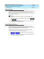
Fiber Optic Interconnect Cabling
Signals between the cabinets are carried by fiber optic cables. Lightwave
transceivers provide the required fiber optic interface.
The fiber optic cables from the DEFINITY System route to a Lightguide
Interconnect Unit (LIU) or fiber optic shelf. Refer to Appendix A, ‘‘Connecting
Fiber Optic Cables’’. Refer to this information for fiber optic equipment comcode
numbers, connecting to LIUs or shelves, and routing through lightguide
equipment.
Use multi-mode fiber transceivers and multi-mode fiber optic cables between
cabinets unless single-mode fiber is required (distance restrictions). Use metallic
cables between carriers.
! CAUTION:
The DEFINITY ECS may contain a Class 1 LASER device if single-mode
fiber optic cable is connected to a remote Expansion Port Network (EPN).
The LASER device operates within the following parameters:
■
Maximum Power Output: -5 dBm
■
Wavelength: 1310 nm
■
Mode Field Diameter: 8.8 microns
CLASS 1 LASER PRODUCT
IEC 825 1993
! CAUTION:
Use of controls or adjustments or performance of procedures other than
those specified herein may result in hazardous radiation exposure.
Contact your Lucent Technologies representative for more information.
DEFINITY Enterprise Communications Server Release 6
Installation and Test for Multi-Carrier Cabinets 555-230-112
1
Install and Connect Cabinets
Fiber Optic Interconnect Cabling
Issue 5
May 1998
Page 1-30
Connect Fiber Optic Cables
NOTE:
Always use the Cable Running List that accompanies the system when
installing fiber optic cables. The following procedure is a typical example of
how to cable a system.
If the cabinets are close together, the signal may go through a single, directlyconnected fiber optic cable. If the cabinets are far apart, it may be easier to
connect the cabinets through an LIU or fiber shelf.
For each fiber indicated in the fiber optic Cable Running List:
1. Install a lightwave transceiver on the cabinet connector at the position in
the FROM column in the running list.
2. Select a cable indicated by the CABLE CODE and LENGTH in the running
list. Connect 1 of the fibers to each connector on the lightwave
transceivers just installed. The fiber is numbered 1 or 2. The connector on
the transceiver is labeled TX or RX. Keep track of which fiber connects to
which transceiver connector. Label both ends of these cables.
3. Route the fiber optic cables from the transceiver out of the cabinet. Secure
the cables to the cable-tie rack. Keep the fiber optic cables clear of the
heavier I/O cables.
4. If the cabinet in the TO column in the running list is located remotely from
the FROM cabinet, connect to the TO cabinet by way of the LIU.
5. Install a lightwave transceiver on the cabinet connector at the position in
the TO column in the running list.
6. Route the cables from the FROM cabinet down into the cable trays of each
EPN cabinet. Connect the cables to the lightwave transceiver just installed
on the TO cabinet.
7. Connect the fiber that comes from the TX connector of the FROM
transceiver to the RX connector of the TO transceiver and vice versa.
8. Route the cables through the cabinet and through cable organizers as
provided. Secure the cables to the cable-tie rack.
Issue 5
May 1998
DEFINITY Enterprise Communications Server Release 6
Installation and Test for Multi-Carrier Cabinets 555-230-112
1
Install and Connect Cabinets
Fiber Optic Interconnect Cabling
Page 1-31
CSS-Connected System with 1 Switch Node
Standard-Reliability
Figure 1-11 shows typical fiber optic cabling between cabinets. The cable
between the EI and SNI on the PPN is a pre-installed metallic cable (H600-278).
1. If no running list is available, use the outer slots first in alternating order.
Connect the first 2 SNI slots to 3 and 20 (the leftmost and rightmost of the
unused slots). Next, use 4 and 19, and so forth.
2. Add links to the EPNs in alternating order (20, 3, 19, 4, 18, 5, and so forth).
Figure Notes
1. Cabinet 1 (PPN with 1 Switch Node)
3. H600-278 Metallic Cable
2. Cabinet 2 through 16 (EPN)
4. To other EPNs
Figure 1-11.
Standard Reliability CSS-Connected Release 6r with 1 Switch
Node
Issue 5
May 1998
DEFINITY Enterprise Communications Server Release 6
Installation and Test for Multi-Carrier Cabinets 555-230-112
1
Install and Connect Cabinets
Fiber Optic Interconnect Cabling
Page 1-32
High-Reliability
Figure 1-12 shows typical fiber optic cabling between cabinets. The cable
between the EI and SNI on the PPN cabinet is a pre-installed metallic cable
(H600-278).
1. Connect the cables between the PPN cabinet and each EPN cabinet in an
alternating port slot order: 3, 19; 4, 18; 5, 17; and so forth. Cabinet 1 is a
Release 6r PPN with 1 Switch Node.
Figure Notes
1. Cabinet 1 (PPN with 1 Switch Node)
3. H600-278 Metallic Cable
2. Cabinet 2 through 15 (EPN)
4. To other EPNs
Figure 1-12.
High-Reliability CSS-Connected with 1 Switch Node
Issue 5
May 1998
DEFINITY Enterprise Communications Server Release 6
Installation and Test for Multi-Carrier Cabinets 555-230-112
1
Install and Connect Cabinets
Fiber Optic Interconnect Cabling
Page 1-33
Critical Reliability
Figure 1-13 shows typical fiber optic cabling between cabinets. The cable
between port slots 1 and 2 on each switch node is a metallic cable (H600-278).
1. Connect the 2 groups of 1 to 15 cables between the PPN and each EPN in
an alternating port slot order: 20, 3; 19, 4; 18, 5; and so forth.
Figure Notes
1. Cabinet 1 (PPN with 1 Duplex Switch
Node)
3. H600-278 Metallic Cable
4. To other EPNs
2. Cabinet 2 through 16 (EPN)
Figure 1-13.
Critical-Reliability CSS-Connected with 1 Switch Node
2. Both connections from each EPN must go to the same slot number. For
example: EPN cabinet 2, 2A1 to 1E3 and cabinet 2, 2B2 to 1D3.
Issue 5
May 1998
DEFINITY Enterprise Communications Server Release 6
Installation and Test for Multi-Carrier Cabinets 555-230-112
1
Install and Connect Cabinets
Earthquake Protection Installation
Page 1-34
Earthquake Protection Installation
Install Concrete Floor Mounting
1. Position the cabinet in the exact position it is to occupy when the
installation is complete.
2. Insert a pencil or marker through the holes previously occupied by the
carriage bolts (front and rear) in the bottom of the cabinet and mark the
floor directly beneath each hole.
3. Roll the cabinet out of the way and drill four 1/2-inch (1.27 cm) diameter
holes about 1.5 inches (3.8 cm) deep at the locations marked in Step 2.
4. Insert concrete floor anchors (STARR part number 3425) into the holes.
5. Roll the cabinet back into place and align the cabinet holes over the
concrete floor anchors.
6. Adjust the leveling legs until the cabinet is level. See Figure 1-14.
NOTE:
If the system is supplied with cable ductwork, the cabinets must be
level from front to rear and from side to side. They must be square
with respect to each other to within ±1/8-inch (0.3 cm).
7. Secure the cabinet to the floor with the 4 supplied 3/8-16 x 4.5-inch (11.4
cm) bolts and four 3/8-inch flat washers.
8. Repeat this procedure for each cabinet to be installed.
Install Raised Computer Floor Mounting
1. Position the cabinet in the exact position it is to occupy when the
installation is complete.
2. Insert a pencil or marker through the holes previously occupied by the
carriage bolts (front and rear) in the bottom of the cabinets and mark the
raised floor panels directly beneath each hole.
3. Roll the cabinet out of the way and drill 4 holes 5/8-inch (1.6 cm) in
diameter through the raised floor panels marked in Step 2.
! CAUTION:
Take care while drilling the holes through the raised floor that the drill
bit does not penetrate any cables below the floor that could cause
damage to the cable or injury to the installer.
4. Insert a long punch through the holes drilled in Step 3 and mark the
concrete floor beneath the raised floor panels.
Issue 5
May 1998
DEFINITY Enterprise Communications Server Release 6
Installation and Test for Multi-Carrier Cabinets 555-230-112
1
Install and Connect Cabinets
Earthquake Protection Installation
Page 1-35
5. Remove the raised floor panels in which the holes were drilled.
6. Using 1/2-inch (1.3 cm) anchor bits, drill a hole at each of the locations
marked in Step 4. Stop drilling when the mark on the side of the bit
reaches the floor level.
7. Insert a concrete floor anchor (STARR part number 3425) into the hole until
the mark on the bit reaches floor level again. Snap the top of the anchor bit
off. Repeat for the remaining holes.
3/8 inch
flat washer
Nut welded
to frame
4 inches
(10.16 cm)
Leveling
foot
3/8 - 16
threaded rod
raised
floor
variable
height
concrete
subfloor
3/8 - 16
Concrete floor
anchor
cab_base CJL 052096
Figure 1-14.
Earthquake Mounting — Raised Computer Floor
DEFINITY Enterprise Communications Server Release 6
Installation and Test for Multi-Carrier Cabinets 555-230-112
1
Install and Connect Cabinets
Earthquake Protection Installation
Issue 5
May 1998
Page 1-36
8. A 3/8-16 threaded rod (part number 845557073) is used to secure the
cabinet to each concrete floor anchor. See Figure 1-14.
Measure the distance from 1 of the anchors to the bottom of the cabinet.
Add 1/2-inch (1.3 cm) to this measurement to allow the rod to be threaded
into the floor anchor. Add an additional 1/2-inch (1.3 cm) to allow the rod
to protrude up through the bottom of the cabinet. For example: if the
distance from the floor anchor to the bottom of the cabinet is 10 inches (25
cm), cut the threaded rod 11 inches (27.9 cm) long.
9. When all 4 threaded rods are cut, replace the raised floor panels removed
in Step 5.
10. Position the cabinet over the holes and adjust the leveling legs until the
cabinet is level.
NOTE:
If the system is supplied with cable ductwork, the cabinets must be
level from front to rear and from side to side. They must be square
with respect to each other to within +-1/8-inch (0.3 cm).
11. Insert the threaded rods through the cabinet bottom and thread into the
concrete floor anchors.
12. Place a 3/8-inch flat washer onto each rod. Thread a 3/8-16 hex nut onto
each rod and tighten securely.
13. Repeat this procedure for each cabinet to be installed (including the
Auxiliary Cabinet and the Stratum 3 Clock Cabinet).
DEFINITY Enterprise Communications Server Release 6
Installation and Test for Multi-Carrier Cabinets 555-230-112
2
2
Install Telecommunications Cabling
Equipment Room Hardware
Install Telecommunications Cabling
Issue 5
May 1998
Page 2-1
2
Equipment Room Hardware
SYSTIMAX 110-type hardware is used for the Main Distribution Frame (MDF).
110-type hardware is available in 2 basic types: the 110A and 110P. The 110A
requires less wall space than the 110P. The 110P includes horizontal and vertical
cable troughs for managing cross-connect cables. The system connects to the
MDF with the supplied B25A 25-pair cables.
Refer to DEFINITY Communications System Generic 1 and Generic 3 Main
Distribution Field Design, 555-230-630, for more information.
Figure 2-1 shows the cross-connections for common circuit packs. Refer to the
figure when cross-connecting wire pairs to the MDF.
DEFINITY Enterprise Communications Server Release 6
Installation and Test for Multi-Carrier Cabinets 555-230-112
2
Install Telecommunications Cabling
Equipment Room Hardware
Figure 2-1.
Example MDF Connections
Issue 5
May 1998
Page 2-2
DEFINITY Enterprise Communications Server Release 6
Installation and Test for Multi-Carrier Cabinets 555-230-112
2
Install Telecommunications Cabling
Equipment Room Hardware
Issue 5
May 1998
Page 2-3
Cross-Connect Fields
Each MDF contains a trunk/auxiliary field and a distribution field. The
trunk/auxiliary field contains 3 cross-connect areas:
1. The green field terminates the network interface leads from the Central
Office (CO) and provides the terminals to cross-connect the leads to the
purple or yellow fields as required. A single row of the 110-type terminal
block can terminate twenty-four 1-pair, eight 3-pair, or twelve 2-pair
trunks.
2. The purple field terminates the trunk circuits from the system with
WP-90929, List 1 or 3 concentrator cables. Also, 25-pair cables can be
used to terminate trunk circuits from the system with each trunk circuit
pack connecting to one 25-pair row of the 110-type terminal block. Each
terminal block row can terminate twenty-four 1-pair, eight 3-pair, or twelve
2-pair trunks.
3. The yellow field provides cross-connect terminals for all miscellaneous
leads from the system, such as alarm monitors, emergency transfer relay
power, and attendant console power. This field is used for emergency
transfer wiring, paging equipment, music sources, and so forth.
The distribution field contains 4 cross-connect areas:
1. The purple field (port field) terminates 25-pair cables from the system.
Each line circuit pack connects to one 25-pair row of the 110-type terminal
block. One 25-pair cable is required for each line circuit pack.
NOTE:
This is the case except for the 16 port analog circuit pack and the
MET circuit pack. The 16-port analog line circuit pack requires an
adapter cable to connect from 1 connector on the system to 2
25-pair connectors on a 110-type terminal block. Two MET circuit
packs require a concentrator cable to connect from 2 connectors on
the system to one 25-pair connector on a 110-type terminal block.
2. The yellow field (auxiliary field) terminates all 25-pair cables from the
auxiliary cabinet and adjunct equipment cabinets. The yellow field is
located in the lower right-hand corner of the distribution field.
3. The white field (station field) terminates the station wiring. The white field
indicates 3-pair station circuits (8 circuits per 25-pair cable) routed
through a satellite closet.
4. The blue field (station field) also terminates station wiring. The blue field
indicates 3- and/or 4-pair station circuits (8 or 6 circuits, respectively, per
25-pair cable). The fourth pair, of the 4-pair station circuit provides adjunct
power from the cross-connect field on an as-needed basis to terminals
within 250 feet (76 m) (wire length) of the MDF.
Issue 5
May 1998
DEFINITY Enterprise Communications Server Release 6
Installation and Test for Multi-Carrier Cabinets 555-230-112
2
Install Telecommunications Cabling
Main Distribution Frame
Page 2-4
Main Distribution Frame
The MDF is located directly behind the system cabinet. Figure 2-2 shows a
typical installation using 900-pair 110P-type terminal blocks.
mccmdf KLC 060596
Figure Notes
1. Multi-Carrier Cabinet
5. Station Distribution Field
2. Z113A Cable Slack Manager
6. Port Distribution Field
3. 25-Pair Cable to System Cabinet
7. Trunk/Auxiliary Field
4. Station Cables
Figure 2-2.
Typical 110A-Type Terminal Blocks
DEFINITY Enterprise Communications Server Release 6
Installation and Test for Multi-Carrier Cabinets 555-230-112
2
Install Telecommunications Cabling
Installation Requirements
Issue 5
May 1998
Page 2-5
Installation Requirements
Sneak Fuse Panels and Emergency Transfer Units
Approximately 8 inches (20 cm) of horizontal wall space is required for each
column of sneak fuse panels. Up to 25 connector pairs can be protected by each
panel. Horizontal wall space must also be provided for emergency transfer units.
110-Type Hardware
The trunk/auxiliary field and the distribution field are mounted on the same wall.
Each 110P-type terminal block is 8.5 inches (21.6 cm) wide. Vertical patch cord
troughs are 5.31 inches (13.4 cm) wide and horizontal patch cord troughs are 23
inches (58.4 cm) wide.
Each 110A-type terminal block is 10.81 inches (27.4 cm) wide; however, no
horizontal patch cord troughs are used and the blocks are shorter than
110P-type terminal blocks. This allows the 110A-type terminal blocks to be
stacked. Therefore, the 110A-type hardware requires less space than the
110P-type hardware on a per-station basis.
Cable Slack Manager
A Cable Slack Manager is 32 inches (81.3 cm) wide. The quantity of which is
determined by dividing the total length of the MDF in inches (cm) by 32 (81.3). A
partial number of 0.4 or less should be rounded down, and a partial number of
0.5 or more should be rounded up (for example: 2.4 = 2 cable slack managers
and 2.5 = 3 cable slack managers).
NOTE:
Cable clamps are required in installations with cable slack managers. At
the rear of the cabinets, on each rear ground plate, install 2 cable clamps
using the screws provided. These clamps hold the 25-pair input/output or
MDF cables in place.
DEFINITY Enterprise Communications Server Release 6
Installation and Test for Multi-Carrier Cabinets 555-230-112
2
Issue 5
May 1998
Install Telecommunications Cabling
Install Equipment and Cables
Page 2-6
Install Equipment and Cables
Hardware Installation
The following procedures assume 1 system technician is performing the
installation. Procedures are provided for installing the following:
■
Main Distribution Frame (MDF)
■
Cable Slack Managers
■
Sneak Fuse Panels
■
Labels for the Main Distribution Frame
Install the Main Distribution Frame
The preferred MDF location is directly behind the system cabinets.
Wall Mounting 110A-Type Terminal Blocks
The 110A-type hardware can be stacked in almost any arrangement at any
height or location on the wall. One arrangement is shown in Figure 2-3. The
distance between the mounting screw holes on the terminal blocks is 10.81
inches (27.4 cm). If a vertical patch cord trough is used, the distance between
the mounting screw holes is 5.31 inches (13.3 cm).
Issue 5
May 1998
DEFINITY Enterprise Communications Server Release 6
Installation and Test for Multi-Carrier Cabinets 555-230-112
2
Install Telecommunications Cabling
Install Equipment and Cables
Page 2-7
r758420b MMR 031496
Figure Notes
1. 4 Feet (1.22 m)
6. 47.5 Inches (120.6 cm)
2. 6.6 Feet (2 m)
7. Horizontal Line
3. 7.68 Inches (19.5 cm)
8. AC Power Strip
4. 7/8-Inch (2.22 cm)
9. Floor Line
5. 5.31 Inches (13.5 cm)
Figure 2-3.
110A-Type Terminal Blocks (300-Pair)
Issue 5
May 1998
DEFINITY Enterprise Communications Server Release 6
Installation and Test for Multi-Carrier Cabinets 555-230-112
2
Install Telecommunications Cabling
Install Equipment and Cables
Page 2-8
Wall Mounting 110P-Type Terminal Blocks
The first terminal block of the trunk/auxiliary field is aligned with the left side of
the system cabinet. See Figure 2-4. This arrangement allows for growth on the
right side of the MDF.
r758421b MMR 031496
Figure Notes
1. 4 Feet (1.22 m)
6. 7/8-Inch (2.22 cm)
2. Horizontal Line
7. 23 Inches (58.4 cm)
3. 7.68 Inches (19.5 cm)
8. 8 Feet (2.43 m)
4. 47.5 Inches (120.6 cm)
9. AC Power Strip
5. 5.31 Inches (13.5 cm)
Figure 2-4.
10. Floor Line
110P-Type Terminal Blocks (900-Pair)
DEFINITY Enterprise Communications Server Release 6
Installation and Test for Multi-Carrier Cabinets 555-230-112
2
Install Telecommunications Cabling
Install Equipment and Cables
Issue 5
May 1998
Page 2-9
1. If you are installing 300-pair terminal blocks, draw a level horizontal line on
the wall 47.5 inches (1.2 m) above the floor. See Figure 2-3.
If you are installing 900-pair terminal blocks, draw a level horizontal line on
the wall 23 inches (58.4 cm) above the floor. See Figure 2-4.
2. To mount the first trunk/auxiliary field terminal block, partially install 2
3/4-inch #12 wood screws, 7-11/16 inches (19.5 cm) apart on the left side
of the horizontal line on the wall.
3. Slide the bottom terminal block feet onto the mounting screws and mark
the upper mounting screw locations.
4. Remove the terminal block and partially install the upper mounting
screws.
5. Place the terminal block on the mounting screws and tighten the screws.
6. If installing a vertical patch cord trough, partially install the first screw for
the patch cord trough, on the line, 7/8-inch (2.2 cm) to the right of the
previous screw. Partially install the second mounting screw 5.31 inches
(13.5 cm) to the right of the screw just installed. Repeat Steps 3, 4, and 5.
7. If another trunk/auxiliary field terminal block is to be installed, partially
install the first screw for the terminal block, on the line, 7/8-inch (2.2 cm) to
the right of the previous screw. Partially install the second mounting screw
7-11/16 inches (19.5 cm) to the right of the screw just installed. Repeat
Steps 3, 4, and 5.
8. If a horizontal patch cord trough is to be installed, install it, on the line,
between the trunk/auxiliary field and the distribution field.
9. To install the first distribution field terminal block, partially install 2 3/4-inch,
#12 wood screws, 7-11/16 inches (19.5 cm) apart on the line, to the right
of the vertical patch cord trough. Repeat Steps 3, 4, and 5.
10. If installing another distribution field terminal block, partially install the first
screw for the terminal block, on the line, 7/8-inch (2.2 cm) to the right of
the previous screw. Partially install the second mounting screw 7-11/16
inches (19.5 cm) to right of the screw just installed. Repeat Steps 3, 4, and
5.
11. If installing a vertical patch cord trough in the distribution field, repeat Step
6.
12. Repeat Steps 10 and 11 until all the terminal blocks and vertical patch
cord troughs in the distribution field are installed.
Frame Mounting 110P-Type Terminal Blocks
The 900-pair 110P-type terminal blocks and the associated patch cord troughs
can also be mounted on a free-standing, floor-mounted 1110A2 Apparatus
Mounting Frame. See Figure 2-5.
Issue 5
May 1998
DEFINITY Enterprise Communications Server Release 6
Installation and Test for Multi-Carrier Cabinets 555-230-112
2
Install Telecommunications Cabling
Install Equipment and Cables
Page 2-10
r781401 LJK 040896
Figure Notes:
1. 1110C1 Apparatus Mounting
4. 88.5 Inches (225 cm)
2. 1110A2 Apparatus Mounting
5. 43.5 Inches (110.5 cm)
3. 76 Inches (193 cm)
Figure 2-5.
1110A2 and 1110C1 Apparatus Mountings
Each 1110A2 provides the space to mount 5 terminal blocks/patch cord troughs
on each side of the frame. A cable support structure, apparatus mounting
1110C1, mounts directly on top of the 1110A2 and provides support for all
cables routed to and from the frame.
Issue 5
May 1998
DEFINITY Enterprise Communications Server Release 6
Installation and Test for Multi-Carrier Cabinets 555-230-112
2
Install Telecommunications Cabling
Install Equipment and Cables
Page 2-11
Apparatus Mounting Frame Ordering Information
Code Number
Description
Comcode
1110A2
Apparatus Mounting Frame
104032495
1110C1
Cable Support Assembly
104175120
1110A1
End Dress Panel
104176268
2110A1
Top Dress Panel
104176276
2110B1
Bottom Dress Panel
104176284
DEFINITY Enterprise Communications Server Release 6
Installation and Test for Multi-Carrier Cabinets 555-230-112
2
Install Telecommunications Cabling
Install Cable Slack Managers
Issue 5
May 1998
Page 2-12
Install Cable Slack Managers
1. Place the Z113A Cable Slack Manager against the wall under the MDF.
See Figure 2-6. Align the left side of the cable slack manager with the first
terminal block of the trunk/auxiliary field.
2. Place the next cable slack manager beside the previously installed unit.
Align the tabs and interlocks and snap the units together.
3. Repeat Step 2 until all cable slack managers are installed.
NOTE:
Nine 1/4-inch holes (0.63 cm) are provided in a cable slack manager
base if earthquake mounting is required. If a base is mounted on an
uneven floor, shims may be required for leveling and to assure
proper fit of the covers.
Holes are provided in the sides of the base for bolting cable slack
manager together. Bolts and shims must be obtained locally.
4. The system cables will route through the cable slack manager as shown.
Complete cable routing is covered later in this chapter.
cbdfflr CJL 102396
Figure Notes:
1. System Cabinet
4. Spare Center Troughs
2. Cable Slack Manager
5. Cabinet Trough for Port Cables
3. Cable Clamp
Figure 2-6.
Cable Routing Through Cable Slack Manager
DEFINITY Enterprise Communications Server Release 6
Installation and Test for Multi-Carrier Cabinets 555-230-112
2
Install Telecommunications Cabling
Install Sneak Fuse Panels
Issue 5
May 1998
Page 2-13
Cable clamps are required in installations with cable slack managers. At the rear
of the cabinets, install 2 cable clamps using the screws provided. These clamps
hold the 25-pair input/output or MDF cables in place. Figure 2-6 shows cable
clamp placement and cable routing.
Install Sneak Fuse Panels
Sneak current protection is required between the incoming RJ21X or RJ2GX
network interface and the system for both trunk and off-premise circuit packs.
The Model 507B sneak current fuse panel, or equivalent, is recommended for
sneak current protection. See Figure 2-7. The panel contains two 25-pair
connectors, fuse removal tool, and fifty 220029 Sneak Fuses (and 2 spares).
B25A connector cables connect the network interface to the sneak fuse panel.
Also, 157B connecting blocks equipped with SCP-110 protectors can be used
for sneak current protection.
Table 2-1.
Sneak Fuse Panel Ordering Information
Description
Comcode
157B Connecting Block
403613003
SCP-110 Protector
406948976
507B Sneak Current Fuse Panel
107435091
220029 Sneak Current Fuse
407216316
NOTE:
Sneak current protectors with a rating of 350 mA at 600 Volts must be UL
listed for domestic installation and CSA certified for Canadian installation.
The 507B includes 52 sneak fuses and 2 cables and can be ordered using
PEC code 63210.
The SCP-110 protectors are used with 110-type hardware and on the 507B
Sneak Fuse Panel. The SCP-110 Protectors can be ordered separately and
installed on the 157B connecting block. Fifty protectors are required per
block.
DEFINITY Enterprise Communications Server Release 6
Installation and Test for Multi-Carrier Cabinets 555-230-112
2
Install Telecommunications Cabling
Install Sneak Fuse Panels
Issue 5
May 1998
Page 2-14
Sneak
Current
Protector
507B
sneak CJL 032096
Figure Notes:
1. Sneak Fuse Panel
3. 25-Pair Female Connector (Out)
2. 25-Pair Male Connector (In)
4. 220029 Fuses (Inside Panel). Use
Small Screwdriver to Pry Top Cover Off
Figure 2-7.
Model 507B Sneak Fuse Panel
1. Locate the 507B near the network interface or the MDF.
2. Hold the panel against the mounting surface and mark the mounting
screw locations. Drill pilot holes at the marked locations and partially
install a locally obtained #12 x 3/4-inch screw into the 2 bottom mounting
slots.
3. Slide the sneak fuse panel onto the mounting screws and tighten the
screws securely.
4. Install a locally obtained #12 x 3/4-inch screw into the top 2 mounting slots
and tighten securely.
5. Repeat the procedure for each sneak fuse panel.
DEFINITY Enterprise Communications Server Release 6
Installation and Test for Multi-Carrier Cabinets 555-230-112
2
Install Telecommunications Cabling
Install Sneak Fuse Panels
Table 2-2 is a pinout of the cable wiring and associated fuse numbers.
Table 2-2.
Sneak Fuse Connector Pinout
Connector
Pin
Numbers
Pair/Fuse
Number
26/1
1
27/2
2
28/3
3
29/4
4
30/5
5
31/6
6
32/7
7
33/8
8
34/9
9
35/10
10
36/11
11
37/12
12
38/13
13
39/14
14
40/15
15
41/16
16
42/17
17
43/18
18
44/19
19
45/20
20
46/21
21
47/22
22
48/23
23
49/34
24
50/25
25
6. Secure the top of each B25A cable with the captive screw on the
connector.
7. Secure the bottom of each cable with a supplied cable tie wrap.
Issue 5
May 1998
Page 2-15
DEFINITY Enterprise Communications Server Release 6
Installation and Test for Multi-Carrier Cabinets 555-230-112
2
Install Telecommunications Cabling
Cable Installation
Issue 5
May 1998
Page 2-16
Cable Installation
Labels
The purple port label shown in Figure 2-8 is installed on both ends of the 25-pair
cables connecting to the trunk/auxiliary field and/or distribution field.
The top blue/yellow building and floor labels are for cables connecting from the
equipment room to a site/satellite location on another floor or in another building.
The yellow label is for auxiliary circuits connecting to the trunk/auxiliary field. The
bottom blue/yellow label is for 25-pair cables connecting to site/satellite closets.
1A2
A
labels LJK 060396
Figure Notes:
1. Purple Label (Port Cable)
3. Yellow Label (Auxiliary)
2. Blue/Yellow Label (Building and
Floor)
4. Blue/Yellow Label (Site or Satellite)
Figure 2-8.
Equipment Room Cabling Labels
Issue 5
May 1998
DEFINITY Enterprise Communications Server Release 6
Installation and Test for Multi-Carrier Cabinets 555-230-112
2
Install Telecommunications Cabling
Cable Installation
Page 2-17
Table 2-3 details the label name and range of each label.
Table 2-3.
Equipment Room Labels
Label Name
Range
Port Cable
1A1-1A20, 1B1-1B20, 1C1-1C20,
1D1-1D20, 1E1-1E20
Building
Field Identified
Floor
Field Identified
Auxiliary Cable
Field Identified
Site or Satellite
A-F and/or Field Identified
Cable/Connector/Building Label Ordering Information
Description
Quantity
Comcode
201A Labels
34 Sheets
103969994
Figure 2-9 shows the proper way to install a label on a 25-pair cable connector.
Install the label near the rear of the connector so it is not obscured by the cabinet
connector retainers. It can also be installed on the skin of the cable near the
connector.
Figure 2-9.
Self-Stick Label on 25-Pair Cable Connector
Issue 5
May 1998
DEFINITY Enterprise Communications Server Release 6
Installation and Test for Multi-Carrier Cabinets 555-230-112
2
Install Telecommunications Cabling
Cable Installation
Page 2-18
Cable Routing Guidelines
General
The following guidelines should be used when installing the equipment room
cabling. Following these guidelines will maximize use of the cable slack
managers and make future cabling additions and changes easier.
Figure 2-10 and Figure 2-11 show typical cable routing from the cabinet to the
top and bottom of the MDF, respectively.
r758424b MMR 052996
Figure Notes:
1. Main Distribution Frame
6. Cable Slack Manager Number 2
2. AC Power Cord (AC-Powered
Cabinets Only)
7. Cable Slack Manager Number 3
3. Cable Slack Manager Number 1
4. Trunk/Auxiliary Field
5. Station Distribution Field
Figure 2-10.
8. System Cabinet(s)
9. To Building Cables
10. 10 AWG (#25) (6 mm2) Wire to
Coupled Bonding Conductor
Cable Routing to Top Terminal Blocks
DEFINITY Enterprise Communications Server Release 6
Installation and Test for Multi-Carrier Cabinets 555-230-112
2
Install Telecommunications Cabling
Cable Installation
Issue 5
May 1998
Page 2-19
r758432b MMR 052996
Figure Notes:
1. Main Distribution Frame
6. Cable Slack Manager Number 2
2. AC Power Cord (AC-Powered
Cabinets Only)
7. Cable Slack Manager Number 3
3. Cable Slack Manager Number 1
4. Trunk/Auxiliary Field
5. Station Distribution Field
Figure 2-11.
8. System Cabinet(s)
9. Building Cables (Through Cable
Trough)
10. 10 AWG (#25) (6 mm2) Wire to
Coupled Bonding Conductor
Cable Routing to Bottom Terminal Blocks
Route Cables to Main Distribution Frame
The following guidelines should be followed when routing cables from the
cabinet to the MDF.
■
Each port cable is connected at the cabinet and then routed along the
front trough of the cable slack manager to the connecting/terminal block
where the cable is to be terminated.
■
Enough slack must be left at the cabinet end of the cable to allow for
proper dressing of the cables.
DEFINITY Enterprise Communications Server Release 6
Installation and Test for Multi-Carrier Cabinets 555-230-112
2
Install Telecommunications Cabling
Cable Installation
■
Issue 5
May 1998
Page 2-20
Route the cable from the cabinet to the wall. Place the cable beside 1 of
the rows of columns in the cable slack manager.
NOTE:
Retainers mounted on the columns keep the cable from protruding
above the top of the base of the cable slack manager.
■
Determine the length of the cable required to reach from the cable slack
manager to the assigned connecting/terminal block.
■
The cable must be supported on the wall using “D” rings.
■
Cable slack is stored by coiling the cable around the columns in the cable
slack manager. The first run should always go across the full length of the
5 columns in the cable slack manager.
■
Connect the cable to the assigned connecting/terminal block.
■
Avoid placing copper cables where they may bend or strain fiber optic
cables.
Install Control Carrier Outputs Cable
A connector on the rear of the Control Carrier is labeled AUX. A 25-pair cable
connects the AUX connector to a 110-type terminal block in the yellow field of
the trunk/auxiliary field. The AUX connector outputs include the following:
■
Alarm monitoring for the processor interface
■
7 DC power (-48 VDC) sources for emergency transfer units
■
3 DC power (-48 VDC) sources for remotely powering a total of 3 attendant
consoles or executive voice terminal adjuncts
■
The remote maintenance internal modem connection location
■
Access to a relay contact is available to actuate a light, bell, or similar type
customer-supplied device. The relay can be administered to make contact
when a major, minor, or warning alarm condition occurs in the system
Label Control Carrier Cable
Place the appropriate AUX connector label on the assigned 110-type terminal
block row. On the control carrier cable, place a yellow auxiliary label on the
connectors at each end of the cable. Write “AUX” on each label.
DEFINITY Enterprise Communications Server Release 6
Installation and Test for Multi-Carrier Cabinets 555-230-112
2
Install Telecommunications Cabling
Cable Installation
Issue 5
May 1998
Page 2-21
Connect Control Carrier Outputs Cable
Plug the connector cable in the AUX connector on the rear of the Control Carrier.
Route the connector cable through the cable slack manager to the assigned
110-type terminal block in the yellow field of the trunk/auxiliary field.
Install Trunk Cables Among Network Interface,
Sneak Fuse Panel, and Cabinet
The 1-pair of Central Office (CO) trunks are installed by the network provider in
the green field. Up to 24 pairs may be terminated on each row of the 110-type
terminal block. Tie trunks also appear in the green field with up to eight 3-pair
trunks terminated on each row of the 110-type terminal block.
Select Concentrator Cables
WP-90929, List 1 and 3 concentrator cables can be used to connect the cabinet
to the 110-type terminal blocks in the purple field. The 1-pair patch cords/jumper
wires are then run from the purple terminal block rows to the green terminal block
rows in order to establish the correct 3-pair modularity.
Connect Trunk Pairs Using Concentrator Cables
Figure 2-12 shows trunk pairs connected to the cabinet with concentrator cables.
To install the cables:
1. Connect B25A cables between the network interface and sneak fuse
panels.
2. Connect A25D cables from the sneak fuse panels to the 110-type terminal
block connectors in the green field.
3. Connect patch cords/jumper wires from the terminal block in the green
field to the associated terminal block in the purple field.
4. Connect the single-fingered end of the concentrator cables to the
110-type terminal block connectors in the purple field in Step 3.
5. Connect the other end (2/3-fingered end) of the concentrator cables to the
appropriate carrier slots. Equipped carrier slots are identified on the CSD.
Mark the nomenclature strips above the carriers to identify the slots.
6. Label connectors on each end of the cables that connect to the cabinet.
7. Route the cables down the sides of the cabinet and store the excess
cable slack in the cable slack manager as previously described.
Issue 5
May 1998
DEFINITY Enterprise Communications Server Release 6
Installation and Test for Multi-Carrier Cabinets 555-230-112
2
Install Telecommunications Cabling
Cable Installation
Page 2-22
NEW796 THC 031296
Figure Notes:
1. Trunk/Auxiliary Field
7. RJ21X/RJ2GX Network Interface
2. To Control Carrier AUX Connector
8. Sneak Fuse Panel
3. Concentrator Cable (WP90929, List 1) 9. B25A Cable
4. Concentrator Cable (WP90929, List 3) 10. Central Office Trunks
5. A25D (Male-to-Male) Cable
11. System Cabinet
6. Alternate Block/Rows
Figure 2-12.
Connect Trunk Pairs Using Concentrator Cables
Issue 5
May 1998
DEFINITY Enterprise Communications Server Release 6
Installation and Test for Multi-Carrier Cabinets 555-230-112
2
Install Telecommunications Cabling
Cable Installation
Page 2-23
Connect Trunk Pairs to Cabinet Using Jumper
Wires To Establish 3-Pair Modularity
Figure 2-13 on page 2-23 and Figure 2-14 on page 2-24 show trunk pairs
connected to the cabinet with jumper wires to establish 3-pair modularity.
1 2 3 4 5 6 7 8
9 10 11 12 13 14 15 16
17 18 19 20 21 22 23 24
1 4 7 10 13 16 19 22
1 4 7 10 13 16 19 22
1 4 7 10 13 16 19 22
r758425b MMR 031496
Figure Notes:
1. Green Field
3. Pairs
2. 1-Pair Jumpers
4. Purple Field
Figure 2-13.
3-Pair Modularity for Trunk Pairs for 1-Pair Trunks
To connect the trunk pairs to the purple field:
1. Connect B25A cables between the network interface and the sneak fuse
panels. See Figure 2-13.
2. Connect A25D/B25A cables from the sneak fuse panels to the 110-type
terminal block-type connecting block connectors in the green field.
3. Connect 1-pair patch cords/jumper wires from each 110-type terminal
block row in the green field to the 110-type terminal block rows in the
purple field for 1-pair Central Office (CO) trunks or in Figure 2-14 on page
2-24 for 3-pair tie trunks.
Issue 5
May 1998
DEFINITY Enterprise Communications Server Release 6
Installation and Test for Multi-Carrier Cabinets 555-230-112
2
Install Telecommunications Cabling
Cable Installation
Page 2-24
3
1 2 3 4 5 6 7 8 9 10 11 12
13 14 15 16 17 18 19 20 21 22 23 24
1 2 3 4 5 6 7 8 9 10 11 12
1 2 3 4 5 6 7 8 9 10 11 12
r758537b MMR 031496
Figure Notes:
1. Green Field
3. Pairs
2. 1-Pair Jumpers
4. Purple Field
Figure 2-14.
3-Pair Modularity for Trunk Pairs for 3-Pair Tie Trunks
Install Cables Between Cabinet and MDF
1. Install “D” rings on the wall between the cable slack manager and the
terminal/connecting blocks mounted on the MDF.
2. Install a self-adhesive port label on the back of each connector on the
connector cable. Labels should be positioned so they are not covered by
the cabinet connector retainers.
3. At the rear of the cabinet, connect 1 end of the connector cable to the
assigned connector.
4. Route the cable down the rear of the cabinet, through the cable slack
manager, and to the MDF.
5. At the MDF, connect the other end of the cable to the assigned terminal/
connecting block connector.
6. Store the cable slack in the cable slack manager.
7. Repeat Steps 2 through 6 until all cables are installed.
DEFINITY Enterprise Communications Server Release 6
Installation and Test for Multi-Carrier Cabinets 555-230-112
2
Install Telecommunications Cabling
Cable Installation
Issue 5
May 1998
Page 2-25
Install Connector Cables Between Auxiliary
Cabinet and MDF
Auxiliary equipment that connects to the MDF can be mounted inside the
Auxiliary cabinet. The equipment connects to an ED-1E1443-10 (Group 1)
intraconnection panel mounted in the cabinet. This intraconnection panel
consists of a 110-type 100-pair wiring block. Auxiliary equipment is connected to
the 110-type wiring block. The wiring block is pre-wired to four 25-pair female
connectors mounted on the outside rear of the cabinet.
1. Install “D” rings on the wall between the cable slack manager and the
terminal/connecting blocks mounted on the MDF.
2. Install a self-sticking port label on the rear of each connector on the B25A
connector cable. See Figure 2-9 on page 2-17.
NOTE:
Labels should be positioned so they will not be obscured by the
cabinet connector retainers.
3. At the rear of the Auxiliary cabinet, connect 1 end of the connector cable
to the assigned connector.
4. Route the cable down the rear of the cabinet and through the cable slack
manager to the MDF.
5. At the MDF, connect the other end of the cable to the assigned
terminal/connecting block connector.
6. Store the excess cable in the cable slack manager.
7. Repeat Steps 2 through 6 until all cables are installed.
DEFINITY Enterprise Communications Server Release 6
Installation and Test for Multi-Carrier Cabinets 555-230-112
2
Install Telecommunications Cabling
Install Coupled Bonding Conductor
Issue 5
May 1998
Page 2-26
Install Coupled Bonding Conductor
The Coupled Bonding Conductor (CBC) connects to the single-point ground
block and runs adjacent to pairs in an associated telecommunications cable.
See Figure 2-15. The mutual coupling between the CBC and the wire pairs
reduces potential differences in terminating equipment.
The conductor consists of a 10 AWG (#25) (6 mm2) wire tie-wrapped to the inside
wiring cable and terminated at the CBC terminal bar at the MDF. Maintain a
minimum of 12 inches (30.5 cm) spacing between the CBC and other power and
ground leads.
The 10 AWG (#25) (6 mm2) wire must be long enough to reach the
telecommunications cables at the rear of the system cabinets, follow these
cables to the MDF, and to terminate at the CBC.
1. Cut a 10 AWG (#25) (6 mm2) wire long enough to reach from the system’s
single-point ground block or DC power cabinet ground discharge bar to
the MDF CBC block.
2. Connect 1 end of the 10 AWG (#25) (6 mm 2) wire to the single-point
ground block (or ground discharge bar).
3. Route the wire next to the 25-pair cables connecting to the trunk/auxiliary
(purple) field.
4. Tie wrap the 10 AWG (#25) (6 mm2) wire to the 25-pair cables.
5. Connect the 10 AWG (#25) (6 mm2) wire to the MDF CBC ground block.
6. Repeat the above steps for each CBC ground wire.
Issue 5
May 1998
DEFINITY Enterprise Communications Server Release 6
Installation and Test for Multi-Carrier Cabinets 555-230-112
2
Install Telecommunications Cabling
Install Coupled Bonding Conductor
Page 2-27
cbc_gnd_1 PDH 062696
Figure Notes:
1. 25-Pair Tip & Ring Cables to
Cabinets
2. Coupled Bonding Conductor (CBC)
Terminal Block
3. Tie Wraps
4. Cable Shield or Six Spare Pairs
5. Ground on Carbon Block Protector
or Equivalent
6. Trunk Cable to Network Interface
8. To Network Cabinets
9. Battery Plant Ground Discharge Bar
for Single-Point Ground
10. Cross-Connect Ground Block
11. Main Distribution Frame (MDF)
12. To Other Cross-Connect Ground
Blocks
13. Approved Ground
14. Coupled Bonding Conductor (CBC)
7. 10 AWG (#25) (6 mm2) Wire
Figure 2-15.
Coupled Bonding Conductor
DEFINITY Enterprise Communications Server Release 6
Installation and Test for Multi-Carrier Cabinets 555-230-112
2
Install Telecommunications Cabling
Station Wiring Design
Issue 5
May 1998
Page 2-28
Station Wiring Design
The following hardware and cabling is used:
■
Information outlets (modular wall jacks)
■
Station Cables
■
Closets
— Site locations
— Satellite locations
■
Adapters
■
Labels
A brief description of each of the above listed items follows. Ordering information
is not provided for station cables and information outlets.
Information Outlets
Information outlets are 8-pin modular wall jacks. Most of the outlets are wired with
push-on connections. Information outlets are also available that connect to a
double modular plug-ended 4-pair station cable routed from the MDF, a
site/satellite location, or an adapter.
Station Cables
For clarity, a station cable is either a 25-pair cable, multiple 25-pair cable, or
4-pair D-inside wire (DIW) run from the equipment room, site/satellite location, or
adapter to the information outlets. The following station cables are available. See
Figure 2-16.
25-pair station cable — Use between the equipment room and site/ satellite
locations or adapters. Use an A25D cable (male to male) between the equipment
room and satellite closet. Use a B25A cable between the equipment room and
site closet or adapter.
Multiple 25-pair station cable — Use between the equipment room and
site/satellite locations or adapters. This cable consists of individually sheathed
25-pair cables with a factory-installed 25-pair connector on each end. Use a
male to female cable to connect between the equipment room and site location
or adapter. Use a male to male cable to connect between the equipment room
and satellite location. Staggered-finger cables are recommended for all multiple
25-pair station cables and are available in both double-ended and single-ended
types.
DEFINITY Enterprise Communications Server Release 6
Installation and Test for Multi-Carrier Cabinets 555-230-112
2
Install Telecommunications Cabling
Station Wiring Design
Issue 5
May 1998
Page 2-29
Single modular plug-ended 4-pair station cable — Use this cable between
adapters and information outlets that require push-on connections. It can also be
used when 4-pair station cables are field- terminated on the 110-type terminal
blocks in the equipment room or satellite closet and modularly connected to
information outlets. The station cables are available in the following lengths:
— 10 feet (3.05 m)
— 25 feet (7.62 m)
— 50 feet (15.24 m)
— 75 feet (22.86 m)
— 100 feet (30.5 m)
— 150 feet (45.72 m)
— 200 feet (61 m)
NOTE:
If more than 200 feet (61 m) of 4-pair station cable is required, a
451A in-line adapter (double-ended modular female connector) is
attached to the cable and a second 4-pair cable of the required
length is plugged into the adapter. See Figure 2-16.
Double modular plug-ended 4-pair station cable — Use this cable to provide
nonstandard length runs between adapters and information outlets with push-on
connections. It can also be used between adapters and modularly connected
information outlets. It is available in the same lengths as the single modular
plug-ended cable.
Bulk Cable — Same as the 25-pair cable or multiple 25-pair cable; however, the
bulk cable is not equipped with connectors. Use this cable between the
equipment room and satellite closets when both are equipped with punch-down
type terminal/connecting blocks.
4-pair station cable — Use this cable when 4-pair station cables are to be
field-terminated on the 110-type terminal blocks in the equipment room or
satellite closet and the information outlets require push-on connections.
451A Adapter Ordering Information
Color
Comcode
Gray
103942272
Ivory
103786240
Issue 5
May 1998
DEFINITY Enterprise Communications Server Release 6
Installation and Test for Multi-Carrier Cabinets 555-230-112
2
Install Telecommunications Cabling
Station Wiring Design
Page 2-30
1
2
5
4
3
5
crdfad1 CJL 101596
Figure Notes:
1. Station Cable
4. 258A Adapter
2. Information Outlet
5. 4-Pair Station Cable
3. 451A In-Line Adapter
Figure 2-16.
Example of Extending 4-Pair Station Cables
Closets
Site Locations
Site locations are closets that provide a point in the station wiring for the
administration of remote powering. Adapters are used at site locations to
terminate the 25-pair station cables and provide connection points (modular
jacks) for power adapters and 4-pair station cables.
The 258A and BR2580A adapters plug into a 25-pair female cable connector.
These adapters divide the 25-pair cable into six 4-pair (modular jack) circuits.
See Figure 2-17.
Issue 5
May 1998
DEFINITY Enterprise Communications Server Release 6
Installation and Test for Multi-Carrier Cabinets 555-230-112
2
Install Telecommunications Cabling
Station Wiring Design
Page 2-31
1
2
3
4
4
crdfadp CJL 101596
Figure Notes:
1. BR2580A Adapter
3. 25-Pair Male Ribbon Connector
2. 258A Adapter
4. 4-Pair Modular Jacks (8 Pins)
Figure 2-17.
258A and BR2580A Adapters
The 356A adapter plugs into a 25-pair female cable connector. See Figure 2-18.
The 356A adapter divides the 25-pair cable into eight 3-pair circuits. Although
the circuits are 3-pair, the adapters modular jacks will accept the 8-wide modular
plug used on the 4-pair station cable.
! CAUTION:
Adapters wired similarly to the 356A should not be used. Their jacks do not
accept 4-pair plugs.
Issue 5
May 1998
DEFINITY Enterprise Communications Server Release 6
Installation and Test for Multi-Carrier Cabinets 555-230-112
2
Install Telecommunications Cabling
Station Wiring Design
Page 2-32
1
2
crdf356 CJL 101296
Figure Notes:
1. 356A Adapter
Figure 2-18.
2. 4-Pair Modular Jacks (6 pins each,
connected to 25-pair ribbon connector)
356A Adapter
Use the ZD8AJ adapter to connect a Multi-button Electronic Telephone (MET)
line cord to an information outlet. The adapter interchanges pairs 3 and 4 to
correspond with the pair assignments for the telephone. The line cord plugs into
the adapter, and then the adapter plugs into an information outlet.
Adapter Ordering Information
Description
Comcode
258A Adapter
102605136
BR2580A Adapter
403384720
356A Adapter
104158829
400B Adapter
103848859
400B2 Adapter
104152558
ZD8AJ Adapter
103881421
DEFINITY Enterprise Communications Server Release 6
Installation and Test for Multi-Carrier Cabinets 555-230-112
2
Install Telecommunications Cabling
Station Circuit Distribution from Equipment Room
Issue 5
May 1998
Page 2-33
Satellite Locations
Satellite locations are closets that provide an administration point (using
cross-connect equipment) for station cables and where adjunct power may be
applied. The station cable circuits from the equipment room MDF are 3-pair. At
the satellite location, 4-pair circuits run to the information outlets. The hardware
used is 110-type terminal blocks.
Satellite Locations Using 110-Type Hardware
Each terminal block has a 3-pair (white field) and a 4-pair (blue field) located on
the same terminal block.
The 110A-type terminal block that can be used is the 110AE1-75FT. It must be
field-terminated to both the white and blue fields.
The 300-pair 110P-type terminal blocks that can be used are:
■
■
110PE1-300CT/FT — 25-pair connector on the white field and
field-terminated on the blue field
110PE1-300FT — Field-terminated on both the white and blue fields
The 900-pair 110P-type terminal blocks that can be used are:
■
■
110PE1-900CT/FT — 25-pair connector on the white field and
field-terminated on the blue field
110PE1-900FT — Field-terminated on both the white and blue fields
Station Circuit Distribution from
Equipment Room
This section explains the station circuit distribution from the equipment room to
the information outlets for new wiring installations. Example connection diagrams
are provided to show the options for running and connecting the station cables.
If most of the telephones/voice terminals that require remote powering are within
250 feet (76.2 m) of the equipment room, 4-pair station circuits are run from the
equipment room to the information outlets. If this is not the case, or if the
customer requires 2-point administration, 3-pair station circuits are run from the
equipment room to satellite locations. Then, the 4-pair station circuits are run
from the satellite locations to the information outlets.
A list of voice and data terminals that can be connected to the system is
provided in Table 2-4 on page 2-40. A list of administration terminals that can be
connected to the system is provided in Table 2-5 on page 2-44.
Issue 5
May 1998
DEFINITY Enterprise Communications Server Release 6
Installation and Test for Multi-Carrier Cabinets 555-230-112
2
Install Telecommunications Cabling
Station Circuit Distribution from Equipment Room
Page 2-34
4-Pair Station Circuits
Four-pair circuits can be run directly from an equipment room MDF to a 258A or
BR2580A adapter as shown in Figure 2-19. The 4-pair station cables connect the
adapter to the information outlets.
1
2
3
7
6
4
8
8
10
11
12
13
9
12
r764797a CJL 031396
Figure Notes:
1. Part of Main Distribution Frame (MDF)
8. B25A Cable
2. 3-Pair Connecting Blocks
9. Connectorized (Staggered
Finger) Multiple 25-Pair Cable
3. 4-Pair Connecting Blocks
4. Purple Field
11. Information Outlet
5. Blue Field
6. Patch Cord or Cross-Connect Jumpers
7. To System Cabinet (Three-Pair
Modularity)
Figure 2-19.
10. 258A or BR2580A Adapter
12. 4-Pair Circuit
13. DIW Station Cable (D-Inside
Wire)
4-Pair Circuit Distribution and Connectivity
Issue 5
May 1998
DEFINITY Enterprise Communications Server Release 6
Installation and Test for Multi-Carrier Cabinets 555-230-112
2
Install Telecommunications Cabling
Station Circuit Distribution from Equipment Room
Page 2-35
The 4-pair station cables can be run directly from the equipment room to the
information outlets if 4-pair terminal blocks are used in the distribution field. See
Figure 2-20. The station cables must be field-terminated on the 110-type terminal
blocks.
2
1
5
2
4
3
r764798a CJL 030796
Figure Notes:
1. Station Side of MDF or Satellite
Location
2. 4-Pair Circuit
Figure 2-20.
3. Blue Field
4. DIW Station Cable (D-Inside Wire)
5. Information Outlet
4-Pair Run to Equipment Room or Satellite Location
Issue 5
May 1998
DEFINITY Enterprise Communications Server Release 6
Installation and Test for Multi-Carrier Cabinets 555-230-112
2
Install Telecommunications Cabling
Station Circuit Distribution from Equipment Room
Page 2-36
If 110-type terminal blocks are used with a modular plug-ended station cable, an
adapter can be connected directly to the 110-type terminal block connectors.
See Figure 2-21.
1
9
3
2
8
11
7
10
5
4
6
r758532a CJL 031196
Figure Notes:
1. Part of MDF
2. 3-Pair Connecting Blocks
3. 4-Pair Connecting Blocks
4. Purple Field
5. Patch Cord or Cross-Connect Jumpers
6. Blue Field
Figure 2-21.
7. To System Cabinet (3 pair
modularity)
8. A25D Cable
9. 258A or BR2580A Adapter
10. Information Outlet
11. 4-Pair Circuit (DIW station
cable (D-Inside Wire))
4-Pair Run to Equipment Room or Satellite Location
Issue 5
May 1998
DEFINITY Enterprise Communications Server Release 6
Installation and Test for Multi-Carrier Cabinets 555-230-112
2
Install Telecommunications Cabling
Station Circuit Distribution from Equipment Room
Page 2-37
3-Pair to 4-Pair Station Circuit Distribution
Figure 2-22 shows the 3-pair circuit distribution from an equipment room MDF to
a satellite location using 110-type hardware. Four-pair circuits are distributed
from the satellite location to the information outlets.
1
2
3
6
8
3
7
15
4
2
10
12
13
9
16
14
8
4
11
Figure Notes:
1. Part of MDF
2. 3-Pair Connecting Blocks
3. Purple Field
4. White Field
5. Patch Cord or Cross-Connect
Jumpers
9. Connectorized (staggered finger)
Multiple 25-Pair Cable
10. 4-Pair Connecting Blocks
11. Blue Field
12. 258A or BR2580A Adapter
13. Information Outlet
6. To System Cabinet (3 Pair Modularity) 14. 4-Pair Circuit [DIW Station Cable
(D-Inside Wire)]
7. A25D Cable (3-Pair Circuits)
15. Part of Satellite Location
8. B25A Cable
16. 4-Pair Circuits (B25A Cable)
Figure 2-22.
3-Pair to 4-Pair Satellite Location Connectivity
Issue 5
May 1998
DEFINITY Enterprise Communications Server Release 6
Installation and Test for Multi-Carrier Cabinets 555-230-112
2
Install Telecommunications Cabling
Station Circuit Distribution from Equipment Room
Page 2-38
Three-pair circuits can also be run directly from the equipment room MDF to a
356A adapter as shown in Figure 2-23. Four-pair station cables connect the
adapter to the information outlets. Four-pair station cables can be run directly
from a satellite location to the information outlets as previously described.
1
2
2
9
8
10
6
7
5
11
12
3
4
r758533a CJL 031196
Figure Notes:
1. Part of Main Distribution Frame (MDF)
7. B25A Cable
2. 3-Pair Connecting Blocks
8. 3-Pair Circuits
3. Purple Field
9. 356A Adapter
4. Blue Field
10. Information Outlet
5. Patch Cord or Cross-Connect Jumpers
11. 3-Pair Circuit in 4-Pair Wire
6. To System Cabinet (3-Pair Modularity)
12. DIW Station Cable (D-Inside
Wire)
Figure 2-23.
3-Pair to 4-Pair Circuit Distribution and Connectivity
NOTE:
Bridged taps are not allowed on any part of the station wiring.
DEFINITY Enterprise Communications Server Release 6
Installation and Test for Multi-Carrier Cabinets 555-230-112
2
Install Telecommunications Cabling
Layout
Issue 5
May 1998
Page 2-39
Layout
Locate Information Outlets
The customer or marketing representative must provide floor plans showing the
information outlet locations and types (flush- or surface-mounted) required. The
floor plans must also show a complete overview of all conduit and cabling
facilities in the building.
Locate Satellites and Sites
Use the following information when determining site, satellite, or adapter
locations.
a. Keep the number of locations to a minimum.
b. To minimize the station wiring distances, centrally locate the
sites/satellites, or adapters among the information outlets.
c. Site/satellite locations must be easily accessible and contain AC-powered
receptacles.
Adapter Requirements
One 258A/BR2580A adapter is required for each 25-pair station cable containing
4-pair station circuits. One 356A adapter is required for each 25-pair station
cable containing 3-pair station circuits.
Hardware Requirements
Hardware requirements are the same as for the equipment room.
Sizing 4-Pair Station Cables
Use the scale of the floor plan to determine the approximate length of the station
cables required per the standard SYSTIMAX wiring concepts.
Sizing 25-Pair and Multiple 25-Pair Station
Cables
Use the scale of the floor plan to determine the approximate length of each
25-pair station cable. The cables must be selected and properly sized to make
maximum use of the hardware at the equipment room or satellite location.
Use 25-pair B25A cables to connect adapters directly to the MDF or satellite
location. Staggered-finger cables, equipped with factory-installed 25-pair
connectors at both ends, should be used when multiple 25-pair cables are used
Issue 5
May 1998
DEFINITY Enterprise Communications Server Release 6
Installation and Test for Multi-Carrier Cabinets 555-230-112
2
Install Telecommunications Cabling
Voice and Data Terminals
Page 2-40
between the equipment room or satellite location and the adapters. B25A cables
are required at the equipment room or satellite location to connect the
staggered-finger cables to the 110-type terminal blocks.
Use the following information to determine the cable size (cable pairs) required
for either 3-pair or 4-pair circuits. Note the length and size on the floor plan to aid
in the ordering and installation of the station cables.
3-Pair Station Cable Circuits
To determine the size of station cables containing 3-pair circuits, multiply the
number of 3-pair circuits required at the satellite location by 3.5. Then, using the
minimum size cable requirement, round up the cable size requirement to the next
highest available cable bundle size. This will provide additional pairs for growth
and compensate for every twenty-fifth pair in a cable that is not used.
4-Pair Station Cable Circuits
To determine the size of station cables containing 4-pair circuits, find out how
many information outlets are served by the equipment room MDF or satellite
location MDF. Multiply the number of information outlets by 4. Then, using the
minimum size cable requirement, round up the cable size requirement to the next
highest available cable bundle size.
NOTE:
This formula may not compensate for the unused twenty-fifth pair in all
cases. If not, it must be allowed for.
Voice and Data Terminals
The system can connect to all DTE terminals and have RS-232 (or EIA-232) or
DCP interfaces. Table 2-4 lists some of the terminals that can connect to the
system. Contact your Lucent Technologies representative for more information.
Table 2-4.
Voice and Data Terminals
Station Type
Type
Analog sets:
500, 2500, 7101A, 7103A, 7104A, 8110, DS1SA, and
DS1FD
Analog voice
Other Analog Ports1, Wired Spare Ports, and Non-wired Analog voice
Spare Ports
Continued on next page
Issue 5
May 1998
DEFINITY Enterprise Communications Server Release 6
Installation and Test for Multi-Carrier Cabinets 555-230-112
2
Install Telecommunications Cabling
Voice and Data Terminals
Table 2-4.
Page 2-41
Voice and Data Terminals — Continued
Station Type
Type
10MET set — 10 buttons
20MET set — 20 buttons
30MET set — 30 buttons
Voice
Terminal — 510 BCT
Terminal — 515 BCT
Data
602A1 Callmaster I
603A1 Callmaster II
603D1 Callmaster III
603E1 Callmaster III
606A1 Callmaster IV
Data and voice
Digital set — 6402
Digital set — 6408
Digital set — 6408D
Digital set — 6408D+
Digital set — 6416D+
Digital set — 6416D+w/XM24B expansion module
Digital set — 6424D+
Digital set — 6424D+w/XM24B expansion module
Digital voice
Voice/data — 6538
Data and voice
Hybrid
Hybrid
Hybrid
Hybrid
Hybrid
Hybrid
Hybrid
Hybrid
Hybrid voice
set — 7303S
set — 7305S
set — 7309H
set — 7313H
set — 7314H
set — 7315H
set — 7316H
set — 7317H
Continued on next page
Issue 5
May 1998
DEFINITY Enterprise Communications Server Release 6
Installation and Test for Multi-Carrier Cabinets 555-230-112
2
Install Telecommunications Cabling
Voice and Data Terminals
Table 2-4.
Page 2-42
Voice and Data Terminals — Continued
Station Type
Type
Digital set — 7401D/7401+
Digital set — 7403D
Digital set — 7404D
Digital set — 7404D w/display
Digital set — 7405D
Digital set — 7405D w/display
Digital set — 7405D w/cov
Digital set — 7406D
Digital set — 7406D w/display
Digital set — 7406+
Digital set — 7406+ w/display
Digital set — 7407D
Digital set — 7407+
Digital set — 7410D
Digital set — 7410+
Digital set — 7434D
Digital set — 7434D w/display
Digital set — 7434D w/call coverage module
Digital set — 7444D
Digital voice
Digital set — 8403B
Digital set — 8405B/B+
Digital set — 8405D/D+
Digital set — 8410B
Digital set — 8410D
Digital set — 8411B
Digital set — 8411D
Digital set — 8434 D
Digital set — 8434 with XM24B Expansion Module
Digital set — 9403B
Digital set — 9410D
Digital set — 9434D
Digital voice
Basic attendant console (302A, 302B)
Enhanced attendant console (302C)
Attendant selector console (26B1)
Data and voice
ISDN-BRI
— 7505D
— 7506D
— 7507D
— 8503D
— 8510T w/display
— 8520T w/display
BRI voice
Wireless 9601A2
Voice
Continued on next page
Issue 5
May 1998
DEFINITY Enterprise Communications Server Release 6
Installation and Test for Multi-Carrier Cabinets 555-230-112
2
Install Telecommunications Cabling
Voice and Data Terminals
Table 2-4.
Page 2-43
Voice and Data Terminals — Continued
Station Type
Type
ADJLK3
Voice
ADX8D
ADX16A
ADX16D
ASAI
CP9530
DIG800
K2500
MDC9000
MDW9000
PC
VMI4
VMIFD4
VMISA4
VRU5
VRUFD
VRUSA
WCBRI
105TL
Voice
Continued on next page
1. Includes music-on-hold, recorded announcement, and loudspeaker paging.
2. The radio controller supports 24 simultaneous calls and 2 wireless fixed bases.
3. Needs ASAI interface and ASAI prop adjunct links turned on in “system-parameters
customer options.”
4. Turn on mode code in ”system-parameters customer options.”
5. Needs DTMF turned on in “system-parameters customer options.”
The following notes apply to the button and data module records in Table 2-4:
■
Any DCP station (except 8400-series) can add a 7400B, requiring 1 data
module record.
■
A data module can be added to a 7403D or 7405D, requiring 1 data
module record.
■
A data module (ADM-T) can be added to a 7505D, 7506D, or 7507D,
requiring 1 data module record.
■
An ISDN-BRI endpoint record is required for each distinct ISDN-BRI
endpoint. Thus each voice-only, data-only, or voice-data endpoint uses 1
of these records.
DEFINITY Enterprise Communications Server Release 6
Installation and Test for Multi-Carrier Cabinets 555-230-112
2
Install Telecommunications Cabling
Label the Main Distribution Frame
Issue 5
May 1998
Page 2-44
Administration Terminals
Table 2-5 lists the administration terminals that can be connected to the system.
Table 2-5.
Administration Terminals
Administration Terminal
Application
510D
Remote administration
610D, 513, 610, 615, 7151 BCT,
4410, 4425, and VT220
Management Terminal: administration and
general purpose
515 Business Communications
Terminal (BCT)
Remote administration, general purpose
615 Management Terminal
Management Terminal system
administration and maintenance terminal
715 BCS, 2900/715 BCS, and 715
BCS-2 Management Terminal
Management Terminal system
administration and maintenance terminal
1. The keyboards and terminals are interchangeable when an adapter cable is used.
NOTE:
The 715 BCS (406803148 and 406803155), has a 6-pin mini-DIN keyboard
connector. The 2900/715 BCS (4073113881 and 407313899), has a 6-pin
RJ-11 keyboard jack located on the side of the terminal.
Label the Main Distribution Frame
Figure 2-24 shows the graphic symbols used on labels for the system,
cross-connections, information outlets, and cables. The labels are color-coded to
identify system wiring:
■
Green — To Central Office (CO)
■
Purple — To system ports
■
Yellow
■
■
— To auxiliary equipment and miscellaneous system leads
Blue — To information outlets
White — From Main Distribution Frame to satellite locations (3-pair)
Issue 5
May 1998
DEFINITY Enterprise Communications Server Release 6
Installation and Test for Multi-Carrier Cabinets 555-230-112
2
Install Telecommunications Cabling
Patch Cord/Jumper Installation and Administration
Page 2-45
r758422i LJK 050996
Figure Notes:
1. Write Floor or Building Identification on
Label
2. Cabinet
6. Site/Satellite Closet
7. Tie Circuit
3. Carrier
8. Floor
4. Slot
Figure 2-24.
5. Information Outlet
9. Building
Label Graphic Symbols and Nomenclature
Each 110-type label identifies 2 rows on the 110-type terminal block. The upper
half identifies the row above it and the lower half identifies the row below it. The
labels are inserted into the clear plastic designation strips furnished with the
110-type terminal blocks. The strip is snapped in place between the terminal
block rows. Label code number 220A (comcode 103970000) contains all of the
110-type labels.
Patch Cord/Jumper Installation and
Administration
Before starting the patch cord installation, obtain a copy of the Port Assignment
Record forms from the customer or marketing representative. See Figure 2-25.
These forms contain the port assignments and identify the extension numbers
(Terminal No.) of the telephones/voice terminals. Enter the jack assignments at
the equipment room and indicate if adjunct power is required and where it is
provided (MDF, site/satellite closet, or information outlet).
Issue 5
May 1998
DEFINITY Enterprise Communications Server Release 6
Installation and Test for Multi-Carrier Cabinets 555-230-112
2
Install Telecommunications Cabling
Patch Cord/Jumper Installation and Administration
Page 2-46
PORT ASSIGNMENT RECORD
CARRIER
Extension
Number
Bldg
Flr
New Rm
Slot
Voice
Terminal
Port Jack* Old
Type
Color
01
02
03
04
05
06
07
08
09
10
11
12
Slot
13
14
CKT PK 15
Type
16
17
18
19
20
21
22
23
24
* To be completed by installation technician
Voice
Terminal
Adjunct
Module
Power*
Page
User Name/Use
r764787 PDH 071596
Figure 2-25.
Port Assignment Record Form
When satellite locations are provided, enter the satellite letter designation (“A”
through “F”) and the jack appearance in the equipment room on the form. Also,
enter the floor designation and/or building designation if appropriate. For 1-point
administration, this entry is all that is required.
Labeling
The white label identifying the terminal block row associated with circuits 17 to 24
connects to an identically labeled terminal block row at the satellite closet. See
Figure 2-26. This is always the case for either 1-point or 2-point administration.
Issue 5
May 1998
DEFINITY Enterprise Communications Server Release 6
Installation and Test for Multi-Carrier Cabinets 555-230-112
2
Install Telecommunications Cabling
Patch Cord/Jumper Installation and Administration
Page 2-47
crdf5pr CJL 103096
Figure Notes:
1. Equipment Room
2. Satellite Location
3. Work Location
4. White Row on 110 Terminal Block
5. Purple Row on 110 Terminal Block
6. Blue Row on 110 Terminal Block
8. D-Inside Wire Cut Down to
Connecting Block
9. 258A Adapter
10. Information Outlet
11. Voice Terminal
12. To Port Connector on Cabinet
(Cabinet 1, Carrier A, Slot 03)
7. Central Location for Terminals 1 through 6
Figure 2-26.
Example 3-Pair Labeling to Information Outlet
The satellite symbol must be installed at all connection points between the blue
field and the information outlet. It must also be installed at the information outlet
itself.
Issue 5
May 1998
DEFINITY Enterprise Communications Server Release 6
Installation and Test for Multi-Carrier Cabinets 555-230-112
2
Install Telecommunications Cabling
Patch Cord/Jumper Installation and Administration
Page 2-48
Figure 2-27 shows an example labeling scheme for 4-pair circuits from the
equipment room to the information outlets. The labeling scheme for 3-pair circuits
from the MDF to a satellite location.
crdf4pr CJL 102996
Figure Notes:
1. Equipment Room
6. 258A Adapter
2. To Central Location for Terminals 1 through 6
7. D-Inside Wire Cut Down
to Connecting Block
3. Blue Row on 110 Terminal Block
4. Purple Row on 110 Terminal Block
5. To Port Connector on Cabinet (Cabinet 1,
Carrier A, Slot 03)
Figure 2-27.
8. Information Outlet
9. Voice Terminal
Example 4-Pair Labeling to Information Outlet
DEFINITY Enterprise Communications Server Release 6
Installation and Test for Multi-Carrier Cabinets 555-230-112
2
Install Telecommunications Cabling
Create a Provisioning Plan
Issue 5
May 1998
Page 2-49
Create a Provisioning Plan
Determine an appropriate available port circuit on the system for each telephone,
trunk, and peripheral connection needed, and, in addition, plan for auxiliary
power for Basic Rate Interface (BRI) and certain display sets.
Create a Port Assignment Record to include the following. See Figure 2-25.
■
Station or trunk type or feature/service
■
Building location (floor/room/desk/information outlet)
■
Extension number or trunk group and member number
■
Port circuit location on the system for each endpoint (cabinet/carrier/
slot/circuit)
■
Route from equipment room through equipment closets to each endpoint
■
Auxiliary power supply, if required
DEFINITY Enterprise Communications Server Release 6
Installation and Test for Multi-Carrier Cabinets 555-230-112
2
Install Telecommunications Cabling
Create a Provisioning Plan
Issue 5
May 1998
Page 2-50
DEFINITY Enterprise Communications Server Release 6
Installation and Test for Multi-Carrier Cabinets 555-230-112
3
Issue 5
May 1998
Install Management Terminal and Activate System
Page 3-1
Install Management Terminal and
Activate System
3
3
This chapter contains procedures for installing the management terminal and
bringing the system up to a “no red LEDs” state. This chapter details how to:
■
Install Management Terminal
■
Activate the System
■
Power Up the System
■
Screens and Commands
■
System Administration
■
Set Country Options
■
Change Craft Password
■
Set Date and Time
■
Administer System Configurations (Release 6r)
■
Administer Fiber Links (Release 6r Only)
■
Set System Maintenance Parameters
■
Save Translations
■
Initiate DEFINITY AUDIX Power Procedures
■
Register the System
! CAUTION:
To prevent unnecessary trouble tickets, do not enable the system alarms
(Alarm Origination feature) before completing all installation and
administration procedures. This chapter describes basic system start-up
procedures only and is not intended to identify all system alarms or error
conditions.
DEFINITY Enterprise Communications Server Release 6
Installation and Test for Multi-Carrier Cabinets 555-230-112
3
Install Management Terminal and Activate System
Install Management Terminal
Issue 5
May 1998
Page 3-2
Install Management Terminal
Locate the management terminal within 50 feet (15.2 m) of the system. It may be
necessary to reduce the maximum distance limitation if higher gauge wire is
used or if the capacitive load on the line is increased. In general, connect the
terminal directly to the system with the shortest possible cable. For maintenance
purposes, locate the terminal in the same equipment room as the system or in
sight of the system.
NOTE:
The management terminal in Figure 3-1 is shown for illustration purposes
only and does not represent a specific terminal type.
Figure 3-1.
Typical Management Terminal
The following types of terminals can connect to a system:
— 715 BCS
— 2900/715 BCS
— 715 BCS-2
The following notes apply:
■
This chapter emphasizes terminal installation in Release 6 and later
systems.
■
If the terminal supports a DC-powered system, install a 116A Isolator
(comcode 106005242).
■
Connect an optional printer using a locally obtained EIA cord. See
Appendix B, ‘‘Option Switch Settings’’ for printer option switch settings.
DEFINITY Enterprise Communications Server Release 6
Installation and Test for Multi-Carrier Cabinets 555-230-112
3
Install Management Terminal and Activate System
Install Management Terminal
Issue 5
May 1998
Page 3-3
Unpack and Inspect
1. Unpack the terminal and inspect for damage. Report all damage
according to local requirements.
2. Remove and retain the installation and usage instructions from the carton.
These instructions are needed to set up the terminal after it is installed.
3. Set the terminal, keyboard, and all cables onto the equipment room table.
Install a 715 BCS Terminal
1. Plug the keyboard cable into the 6-pin mini-DIN jack on the rear of the
terminal. See Callout 2 in Figure 3-2 on page 3-4.
2. Plug the supplied 25-pin Data Terminal Equipment (DTE) cable into the P2
port (center connector) on the rear of the terminal.
Install a 2900/715 BCS Terminal
1. Plug the keyboard cable into the 6-pin RJ-11 jack on the left side of the
terminal. An adapter cable is available to convert a 6-pin mini DIN jack to
an RJ-11 jack to allow a 715 BCS keyboard to be used (comcode
847489895 or 847489903).
2. Plug the supplied 25-pin Data Terminal Equipment (DTE) cable into the P2
port (right side connector). See Callout 4 in Figure 3-2 on page 3-4.
Install a 715 BCS-2 Terminal
1. Plug the keyboard cable into the modular keyboard jack on the rear of the
terminal. See Callout 5 in Figure 3-2. This is a unique cable and must be
connected to the 715 BCS-2 only.
2. Plug the supplied 25-pin Data Terminal Equipment (DTE) cable
(H600-426) into the COM1 port (right side connector).
Issue 5
May 1998
DEFINITY Enterprise Communications Server Release 6
Installation and Test for Multi-Carrier Cabinets 555-230-112
3
Install Management Terminal and Activate System
Install Management Terminal
Page 3-4
2
1
1
P2-DTE
P1-DCE
AUX PORT
PAR
COM2
PARALLEL
P1-DCE
P2-DTE
MAIN PORT
COM1
0069_0 RBP 072296
Figure Notes
1. Rear Panel of 715 BCS Terminal
5. Modular Keyboard Jack
2. 6-Pin Mini DIN Connector
6. COM 1 Port
3. Rear Panel of 2900/715 BCS Terminal
7. Rear Panel of 715 BCS-2
Terminal
4. P2-DTE Port
Figure 3-2.
Rear Panels on Management Terminals
Connect to the System
1. Route the 25-pin DTE cable from the terminal to the rear of the system.
2. For Release 6si, connect the cable to the TERM connector. See Figure
3-3. For Release 6r, connect the cable to the Terminal Active connector.
See Figure 3-4.
3. Plug the AC power cord into the AC receptacle on the terminal. Plug the
opposite end of the power cord to the AC receptacle located at the bottom
rear of the cabinet, or into the selected AC receptacle.
4. Set the terminal power switch ON.
Issue 5
May 1998
DEFINITY Enterprise Communications Server Release 6
Installation and Test for Multi-Carrier Cabinets 555-230-112
3
Install Management Terminal and Activate System
Install Management Terminal
Page 3-5
P2
P1
9
8
7
6
5
4
3
2
1
CLOCK AUX
DATA
PROCESSOR COMMUNICATION
EQUIPMENT TERMINAL
INTERFACE
DUPLICATION
OPTION
TERMINAL
0063_0 RBP 071096
Figure 3-3.
Management Terminal Connections for Release 6si
Figure 3-4.
Management Terminal Connections for Release 6r
5. For a DC-powered system, install an EIA 116A Isolator (comcode
106005242) in series between the DTE cable and the TERM or Terminal
Active connector.
DEFINITY Enterprise Communications Server Release 6
Installation and Test for Multi-Carrier Cabinets 555-230-112
3
Issue 5
May 1998
Install Management Terminal and Activate System
Install Management Terminal
Page 3-6
Remotely Connect Terminal
A management terminal can be installed at some distance from the system.
Typical remote connections are shown in Figure 3-5.
Figure Notes
1. Compact Modular Cabinet (Slot 1)
7. Line Cord
2. DCE Connector (RS-232)
8. Remote Modem
3. M25B (25-Pin-to-RS-232) Cable
9. DB9 to DB25 Converter (ED3-1-70,
G115) (optional) to connect to PC
4. Main Distribution Frame (MDF)
5. Public Switched Telephone Network
(PSTN)
6. 103A or Modular Wall Jack
Figure 3-5.
10. Remote Management Terminal or
PC
11. Remote Location
Typical Connections to Remote Devices
1. Use Z3A2 Asynchronous Data Units (ADUs) and M25A cables on
CDRU/CAS+, PMS, SAT PC, BCMS terminal, and Remote SAT.
2. Use Z3A1 ADUs and M25B cables on System/Journal printers.
3. A TN556 ISDN BRI circuit pack is used with the 7500 Data Module.
DEFINITY Enterprise Communications Server Release 6
Installation and Test for Multi-Carrier Cabinets 555-230-112
3
Install Management Terminal and Activate System
Activate the System
Issue 5
May 1998
Page 3-7
Set Up Management Terminal
Each management terminal requires a different setup procedure. Refer to the
installation and usage instructions packed with the management terminal.
Install Management Applications
The PC-based Management Applications are installed according to the complete
installation instructions provided in Management Applications Operations,
585-229-202.
Activate the System
Instructions are provided to activate Release 6 and later systems. To activate a
G3V4 and earlier system, refer to DEFINITY Communications System Generic 3
Installation and Test, 555-230-104.
NOTE:
To prevent unnecessary trouble tickets, do not enable the system alarms
(Alarm Origination feature) until all installation and administration
procedures are completed.
! CAUTION:
It may be necessary to reseat circuit packs. To prevent damage from static
electricity, always wear an Electromagnetic Compatibility (EMC) wrist strap
(comcode 900698226) when handling all system components.
Install Translation Card (Release 6si in MCC
Cabinet)
If a Release 6r system is installed, skip this section.
1. Insert the translation card into the TN777B Network Control circuit pack in
the direction indicated by the arrow on the label.
Power Up the System
AC-Powered System
1. Set the circuit breakers on the AC power panel to ON. If the system is high
or critical reliability, power-up the EPN cabinet first, then the PPN cabinet.
Always power up the PPN cabinet last.
2. Set the cabinet circuit breakers to ON. This starts the system initialization
and test. All red LEDs on the circuit packs go on and then off.
3. Skip to ‘‘Verify Messages on Terminal’’.
DEFINITY Enterprise Communications Server Release 6
Installation and Test for Multi-Carrier Cabinets 555-230-112
3
Install Management Terminal and Activate System
Activate the System
Issue 5
May 1998
Page 3-8
DC-Powered System
1. At the DC Battery Cabinet (if installed), set the circuit breaker to ON.
2. At the DC Power Cabinet, set the circuit breaker(s) on the rectifiers ON.
This starts the system initialization and test. Some red LEDs may be on but
are turned off by other procedures in this chapter.
3. If the system is high or critical reliability, power-up the EPN cabinet first,
then the PPN cabinet. Always power up the PPN cabinet last.
Verify Messages on Terminal
1. After several minutes, verify all tests pass. Screen 3-1 displays the screen
contents of a typical Release 6r system with 3 memory circuit packs. The
Release 6si system screen is similar.
NOTE:
If any of the terminal messages indicate a test has failed or if the message
“spe down mode” is displayed, refer to DEFINITY Enterprise
Communications Server Release 6 Maintenance for R6r, or DEFINITY
Enterprise Communications Server Release 6 Maintenance for R6vs/si, to
clear the trouble.
DEFINITY Enterprise Communications Server Release 6
Installation and Test for Multi-Carrier Cabinets 555-230-112
3
Install Management Terminal and Activate System
Activate the System
Screen 3-1.
Issue 5
May 1998
Page 3-9
Typical Start-up Messages (Release 6r)
2. About 2 minutes after REBOOT PERFORMED displays, the screen displays:
Login:
DEFINITY Enterprise Communications Server Release 6
Installation and Test for Multi-Carrier Cabinets 555-230-112
3
Install Management Terminal and Activate System
Screens and Commands
Issue 5
May 1998
Page 3-10
Screens and Commands
Screens
The system is administered using screens displayed on the terminal. The
screens are used to add, change, display, list data, and to remove system and
telephone features. To access a screen, enter a valid system command in
response to the Command: prompt.
Commands
System commands are standard words and phrases instructing the system to
perform a specific function. The commands are arranged in a hierarchy of
keywords; that is, enter 1 command to go to a different level. The commands
contain three parts: ACTION, OBJECT, and QUALIFIER.
■
ACTION is the first part of the command. When Command: appears on the
screen. The ACTION specifies the operation desired. Examples include
add, duplicate, change, remove, display, list, and save.
■
OBJECT is the second part of the command and specifies the particular
object to be administered. Typical entries are hunt-group, coverage
path, and station.
■
QUALIFIER is the last part of the command. It is 1 or more words or digits
used to further identify or complete the OBJECT. For example, hunt group
15 or station 3600, where 15 and 3600 are qualifiers.
An example of the command line required to add a station with extension number
1234 is add station 1234. In this example, add is the ACTION, station is the
OBJECT, and 1234 is the QUALIFIER. In the command line, spaces are required
between the ACTION, OBJECT, and QUALIFIER.
To save time, enter enough letters for each part of the command to make it
unique. For example, if you want to enter the command change
system-parameters country-options, typing cha sys coun is acceptable.
However, typing the entire command is always best.
NOTE:
The craft login may not be allowed to perform some of the steps needed to
initialize the system. If access is denied to some of these procedures,
contact your Lucent Technologies representative for assistance.
Getting Help
Use the Help key for a list of options and the Cancel key to back out of any
command. Refer to DEFINITY Enterprise Communications Server Release 6
Administration and Feature Description, for detailed procedures.
DEFINITY Enterprise Communications Server Release 6
Installation and Test for Multi-Carrier Cabinets 555-230-112
3
Install Management Terminal and Activate System
System Administration
Issue 5
May 1998
Page 3-11
System Administration
NOTE:
An “init” login is required to perform the following. Contact the regional
CSA (Customer Software Associate) to assign the Offer Category option.
Maintenance capabilities to initialize the system and access to either an
internal or external modem are the only command options available until
the Offer Category option is set.
Log in to the System
1. Verify the screen displays: Login:
2. Type craft and press Enter.
3. Verify the screen displays: password:
4. Type crftpw and press Enter. For security reasons, the password does not
display as it is typed. The system verifies a valid login and password name
were entered. If an invalid login or password name was entered, the
screen displays:
login incorrect:
In this case, repeat the procedure using the correct login and matching
password.
If the system recognizes the login and password name, the screen
displays the software version.
5. Verify the screen display is similar to:
Terminal Type (513, 715, 4410, 4425, VT220): [513]
6. Type the number of the management terminal and press Enter.
7. Verify the screen displays: Command:
NOTE:
The following sections describe some of the procedures used to access
and change certain options. These sections are not intended to replace or
modify the instructions provided in DEFINITY Enterprise Communications
Server Release 6 Administration and Feature Description.
DEFINITY Enterprise Communications Server Release 6
Installation and Test for Multi-Carrier Cabinets 555-230-112
3
Install Management Terminal and Activate System
Set Country Options
Issue 5
May 1998
Page 3-12
Set Country Options
Certain country options need to be set to turn red failure indication LEDs off.
1. Verify the screen displays: Command:
2. Type change system-parameters country options and press Enter.
A screen similar to Screen 3-2 is displayed on the terminal. The cursor is
set on the Companding Mode line.
Screen 3-2.
Typical System Parameters Country-Options Screen
3. The default companding mode is µ-Law. If the country uses A-Law
companding, type A-Law.
4. Press Enter when this information is correct.
Other items eventually need to be entered on this screen, but this is all that
must be done to turn the red alarm LEDs off. Refer to Table 3-1 for a list of
the country codes.
Issue 5
May 1998
DEFINITY Enterprise Communications Server Release 6
Installation and Test for Multi-Carrier Cabinets 555-230-112
3
Install Management Terminal and Activate System
Set Country Options
Page 3-13
Table 3-1.
Country Codes
Country
Code
Country
Code
USA
1
France
12
Australia
2
Germany
13
Japan
3
Czechoslovakia
14
Italy
4
Russia
15
The Netherlands
5
Argentina
16
Singapore
6
Greece
17
Mexico
7
China
18
Belgium
8
Hong Kong
19
Saudi Arabia
9
Thailand
20
United Kingdom
10
Macedonia
21
Spain
11
5. If all red LEDs do not go off, reseat (unplug and reinsert) any
purple-labeled circuit packs displaying red LEDs.
! CAUTION:
To avoid a disk crash, never reset the DEFINITY AUDIX System
without first shutting it down. Shut down the DEFINITY AUDIX System
(and allow the disk to completely spin down) before unplugging the
assembly. See ‘‘DEFINITY AUDIX Power Procedures’’ on page 3-32
for the proper procedures.
6. If the red LEDs still do not go off, refer to DEFINITY Enterprise
Communications Server Release 6 Maintenance for R6r, or to DEFINITY
Enterprise Communications Server Release 6 Maintenance for R6vs/si.
NOTE:
Ignore the red alarm indication LED on the TN767 or TN464 DS1
circuit pack until after the DS1 circuit pack is administered. Alarms
will appear in the Alarm Log when power is applied to the system
before all equipment connecting to port circuit packs is installed.
Normally, some alarms will be logged when power is applied to the
system, but should be resolved quickly. If no equipment is
connected to the port circuit packs, alarms associated with these
ports can take up to four hours to log, but will clear automatically
after all equipment is installed and operating correctly.
DEFINITY Enterprise Communications Server Release 6
Installation and Test for Multi-Carrier Cabinets 555-230-112
3
Install Management Terminal and Activate System
Set Country Options
Issue 5
May 1998
Page 3-14
Change Craft Password
The password for the craft login must be changed by the installing technician to
prevent unauthorized administration changes.
! CAUTION:
After the password is changed, the new password must be safeguarded so
no unauthorized administration changes can be made. This password
MUST NOT BE REVEALED to the customer or to any unauthorized person.
1. Login as craft and enter change password craft. Press Enter.
Screen 3-3.
Typical Change Password Screen
2. Verify the Password Administration screen displays. See Screen 3-3. The
cursor is positioned on Password for Login Making Change:
3. Type the password for the craft login (assigned as crftpw when the system
is shipped) and press Enter. The cursor is positioned on Login’s
Password:.
4. Enter the new password. Valid passwords consist of a combination of 4 to
11 alpha or numeric characters. At least 1 letter and 1 number must be
used in each password. Press Enter.
5. The cursor is positioned on Reenter Login’s Password:. Type the
new password again and press Enter.
6. Verify the screen displays:
command successfully completed
DEFINITY Enterprise Communications Server Release 6
Installation and Test for Multi-Carrier Cabinets 555-230-112
3
Install Management Terminal and Activate System
Set Country Options
Issue 5
May 1998
Page 3-15
Set Date and Time
1. Enter set time and press Enter.
2. Verify the screen displays the Date and Time screen. See Screen 3-4. The
cursor is positioned on the Day of the Week: field.
Screen 3-4.
Typical Date and Time Screen
3. Type the day of the week in English (Sunday through Saturday). See Table
3-2 for English day of the week names.
Table 3-2.
English Day of the Week Names
Day Number
Day Name
1
Sunday
2
Monday
3
Tuesday
4
Wednesday
5
Thursday
6
Friday
7
Saturday
DEFINITY Enterprise Communications Server Release 6
Installation and Test for Multi-Carrier Cabinets 555-230-112
3
Install Management Terminal and Activate System
Set Country Options
Issue 5
May 1998
Page 3-16
4. The cursor is positioned on the Month: field. Type the current month in
English (January through December). See Table 3-3 for English month
names. After the month is entered, press Tab to move to next field.
Table 3-3.
English Month Names
Month Number
Month Name
1
January
2
February
3
March
4
April
5
May
6
June
7
July
8
August
9
September
10
October
11
November
12
December
5. The cursor is positioned on the Day of the Month: field. Type the day
of month (1 through 31) and press Tab to move to the next field.
6. The cursor is positioned on the Year: field. Type the current year and
press TAB to move to the next field.
7. The cursor is positioned on the Hour: field. Type the current hour for a
24-hour clock. Press Tab to move to the next field.
8. The cursor is positioned on the Minute: field. Type current minute (0
through 59). Seconds cannot be set.
9. Press Enter when the information is correct.
10. Type display time and press Enter to verify date/time data.
DEFINITY Enterprise Communications Server Release 6
Installation and Test for Multi-Carrier Cabinets 555-230-112
3
Install Management Terminal and Activate System
Circuit Pack Administration
Issue 5
May 1998
Page 3-17
Circuit Pack Administration
After the equipment is installed (including circuit packs), the circuit packs must
be administered. Refer to DEFINITY Enterprise Communications Server Release
6 Administration and Feature Description for more information.
The following information describes general administration information:
■
Use the Circuit Packs form to administer circuit packs to carrier slots. The
circuit packs must be installed (or assigned using the Circuit Packs form)
before administering voice terminals, attendant consoles, or trunks.
■
Each page of the form represents 1 carrier in the cabinet shown on the
command line. For Release 6si, all carriers and slots appear even if they
are not included in the hardware.
■
It is not necessary to fill in the Circuit Packs form if the circuit packs are
installed at the time of administration.
■
Refer to DEFINITY Communications System Generic 3 Planning and
Configuration, 555-230-601, for more information about circuit pack
administration and port assignment records.
■
For initial installation, assign circuit packs to slots using the hardware
configuration layout record from the factory or Customer Services
Organization. Do not arbitrarily assign circuit packs to slots.
■
For Release 6r, if the carrier type administered on the Cabinet
Administration form does not match the physical hardware, question
marks (??) may display in the Code fields.
■
When a circuit pack in a slot differs from what has been administered on
the form, a “#” displays between the “Sfx” and “Name” fields.
■
For Release 6r, the number of slot fields displayed represents
administrable slots for the given carrier type. For Release 6si
configurations, all slot fields are displayed.
DEFINITY Enterprise Communications Server Release 6
Installation and Test for Multi-Carrier Cabinets 555-230-112
3
Install Management Terminal and Activate System
Set System Maintenance Parameters
Issue 5
May 1998
Page 3-18
Set System Maintenance Parameters
If the system does not contain a TN778 Packet Control circuit pack, skip this
section and proceed to ‘‘Administer System Configurations (Release 6r)’’.
1. Verify the terminal screen displays: Command:
2. Type change system-parameters maintenance and press Enter. Verify
the screen displayed is similar to Screen 3-5. The screen shows default
values and the cursor is positioned on Product Identification: line.
Screen 3-5.
Typical System-Parameters Maintenance Screen
! CAUTION:
To prevent unnecessary trouble tickets, do not enable the system
alarms (Alarm Origination feature) until all installation and
administration procedures are completed.
3. Move the cursor by pressing Tab to move down the screen from field to
field and enter y in the Packet Bus Activated? field to indicate a
TN778 circuit pack is installed. This is the only field needing change on
this screen to turn the red LEDs off.
4. Press Enter when the information is correct.
DEFINITY Enterprise Communications Server Release 6
Installation and Test for Multi-Carrier Cabinets 555-230-112
3
Install Management Terminal and Activate System
Administer System Configurations (Release 6r)
Issue 5
May 1998
Page 3-19
Administer System Configurations
(Release 6r)
If a Release 6si is installed, skip to ‘‘Administer Attendant Console’’ on page 3-29.
Change Customer Options
The following features are part of the basic software package and do not need to
be activated. They default to y (yes) on the Optional Features Form.
■
Automatic Route Selection/Automatic Alternate Routing Partitioning
■
Emergency Access to the Attendant
■
Hospitality
■
Service Observing
An “init” password is required to modify customer options. Contact your regional
CSA for the password.
Use the following procedure to change the customer’s optional features.
1. At the Command: prompt, enter the change system-parameters
customer-options command. A display similar to Screen 3-6 appears.
Issue 5
May 1998
DEFINITY Enterprise Communications Server Release 6
Installation and Test for Multi-Carrier Cabinets 555-230-112
3
Install Management Terminal and Activate System
Administer System Configurations (Release 6r)
Page 3-20
Page
change system-parameters customer-options
1 of
4
OPTIONAL FEATURES
Maximum Ports:
G3 Version: V5
14000
Abbreviated Dialing Enhanced List? n
CAS Main? y
A/D Grp/Sys List Dialing Start at 01? n
Cvg Of Calls Redirected Off-net? n
DCS (Basic)? y
Answer Supervision by Call Classifier? n
ARS? y
ARS/AAR Partitioning? n
DCS Call Coverage? n
Emergency Access to Attendant? y
ASAI Interface? n
Extended Cvg/Fwd Admin? n
ASAI Proprietary Adjuncts Links? n
External Device Alarm Admin? n
ATMS? n
Flexible Billing? n
Audible Message Waiting? n
Forced Entry of Account Codes? n
Authorization Codes? n
Hospitality (Basic)? n
CAS Branch? n
Hopitality (G3V3 Enhancements)? n
Hopitality Parameter Reduction? n
(NOTE: You must logoff & login to effect the permission changes.)
Screen 3-6.
Typical Customer-Options Form
2. Enable the optional features purchased by the customer (as shown by
PEC codes on the Customer Order).
In Release 6 systems, a separate screen offers ASAI capability groups for
selection in cases where the ASAI interface has been enabled. Change
this screen in the same manner as Page 1 of the customer-options form.
Change and Logoff Critical Reliability System
If a critical reliability system is installed (1 with both processor and PNC
duplicated), follow these steps. Otherwise, proceed to ‘‘Change Site-Data’’ on
page 3-21.
NOTE:
Be sure PNC Duplication was set to y in the customer-options form.
1. Log off and log back in as craft.
Issue 5
May 1998
DEFINITY Enterprise Communications Server Release 6
Installation and Test for Multi-Carrier Cabinets 555-230-112
3
Install Management Terminal and Activate System
Administer System Configurations (Release 6r)
Page 3-21
Change Site-Data
This form initializes the building, floor, and color data to make them available
later in help messages that refer to site information.
1. At the Command: prompt, enter the change site-data command.
The first of 3 pages of site data appears:
2. Enter optional names for the buildings or offices served by the system.
3. Access the remaining site-data pages and fill them in appropriately.
Change Cabinet 1
1. Enter change cabinet 1. A screen similar to Screen 3-7 appears.
2. Fill in the blanks as required by the location and nature of the cabinet. If
the system is critical reliability, verify the B field is set to the processor
option, the D field is set to the dup-sw-node option, and the E field is set to
the switch-node option.
Screen 3-7.
Typical Change Cabinet 1 Form
DEFINITY Enterprise Communications Server Release 6
Installation and Test for Multi-Carrier Cabinets 555-230-112
3
Install Management Terminal and Activate System
Administer System Configurations (Release 6r)
Issue 5
May 1998
Page 3-22
Add Cabinet 2 through N (Release 6r)
1. Enter add cabinet <2-44>. See Screen 3-8.
2. Fill in the blanks as required by the location and nature of the cabinet.
Screen 3-8.
Typical Add Cabinet Form
DEFINITY Enterprise Communications Server Release 6
Installation and Test for Multi-Carrier Cabinets 555-230-112
3
Install Management Terminal and Activate System
Administer Fiber Links (Release 6r Only)
Issue 5
May 1998
Page 3-23
Administer Fiber Links (Release 6r
Only)
Administer system fiber link configurations to match the hardware installed and
according to the Fiber Optic Cable Running List.
NOTE:
Fiber link administration interacts with or depends upon other system
features that must be administered before it.
Fiber link administration creates translation data by identifying the endpoint pairs
for each link. Endpoints can be:
■
An Expansion Interface (EI) circuit pack
■
A Switch Node Interface (SNI) circuit pack
Circuit Pack Form
After installing the equipment (including circuit packs), the circuit packs must be
administered before the fiber link is administered. Refer to DEFINITY Enterprise
Communications Server Release 6 Administration and Feature Description for
more information.
The following information describes general circuit pack administration
information:
a. Use the Circuit Packs form to administer circuit packs to carrier slots.
Install or administer the circuit packs (or assigned using the Circuit Packs
form) before administering voice terminals, attendant consoles, or trunks.
b. Each page of the form represents 1 carrier in the cabinet shown on the
command line.
c. Refer to DEFINITY Communications System Generic 3 Planning and
Configuration, 555-230-601, for more information about circuit pack
administration and port assignment records.
d. For initial installation, assign circuit packs to slots using the hardware
configuration layout record from the factory or Customer Services
Organization. Do not arbitrarily assign circuit packs to slots.
e. If the carrier type administered on the Cabinet Administration form does
not match the physical hardware, question marks (??) may display in the
Code fields.
f. When a circuit pack in a slot differs from what has been administered on
the form, a “#” displays between the “Sfx” and “Name” fields to indicate a
conflict.
g. For Release 6r, the number of slot fields displayed represents
administrable slots for the given carrier type.
Issue 5
May 1998
DEFINITY Enterprise Communications Server Release 6
Installation and Test for Multi-Carrier Cabinets 555-230-112
3
Install Management Terminal and Activate System
Administer Fiber Links (Release 6r Only)
Page 3-24
Administer Fiber Links on Simplex Systems
1. Administer the TN570 Expansion Interface and the TN574 or TN1654 DS1
Converter circuit packs. Enter the change circuit packs command and
press Enter. See Screen 3-9.
Screen 3-9.
Circuit Packs Form
2. Scroll through the pages on the form until the carrier containing the new
circuit packs displays. Enter the circuit packs into the appropriate slot
locations on the form. Press Enter when finished.
3. Enter the list fiber command. All administered fiber connections display.
4. If a previously used fiber link is to be reused, enter the add fiber
<number> command. If this is a new fiber link, enter the add fiber next
command. The Fiber Link Administration screen appears. Use this form to
administer fiber links, each of which is identified by a fiber number.
5. Enter y or n in the field Is one endpoint remoted via DS1
Converter complex? and press Enter.
6. Enter the location of the TN570 and the TN574 or TN1654 circuit pack for
both ENDPOINT-1 and ENDPOINT-2.
7. Scroll to page 2 of the form. Enter y as applicable, in each Facility
Installed? field (A, B, C, and D).
8. In the Bit Rate: field, enter either 1.544 (T1) or 2.048 (E1).
9. Enter the idle code in the Idle Code MSB (1) . . . . LSB (8):
field. The default value is 11101000. It is recommended that the default
value be used unless it becomes absolutely necessary to change it. The
“MSB” means Most Significant Bit, the “LSB” means Least Significant Bit.
DEFINITY Enterprise Communications Server Release 6
Installation and Test for Multi-Carrier Cabinets 555-230-112
3
Install Management Terminal and Activate System
Administer Fiber Links (Release 6r Only)
Issue 5
May 1998
Page 3-25
10. In the Line Coding: field, enter the line coding information. This
information should match the line coding of the facility. For T1, example
line coding is b8zs. For E1, example line coding is hdb3.
NOTE:
If this data is not correct, wideband errors (multimedia call handling)
may occur.
11. For T1 sites, refer to ‘‘T1 Installations Only’’. For E1 sites, refer to ‘‘E1
Installations Only’’.
T1 Installations Only
a. The Framing Mode: field is display only and shows the hardware setting.
b. The DS1CONV-1 Line Compensation: and the DS1CONV-2 Line
Compensation: fields are display only and show the hardware setting.
c. In the Facility A Circuit ID: field, enter an optional facility name
that is unique to each facility (up to 40 alphanumeric characters). Press
Enter.
d. A display similar to the following appears after the fiber link administration
is completed:
RESET PORT-NETWORK 2 LEVEL 2 (COLD) PERFORMED.
E1 Installations Only
a. Enter y or n in the CRC? field. The “CRC” means Cyclic Redundancy
Check. This is an error detection algorithm.
b. The Line Termination: field is display only. A 75 (75 Ohms) or 120
(120 Ohms) typically displays.
c. In the Facility A Circuit ID: field, enter an optional facility name
that is unique to each facility (up to 40 alphanumeric characters). Press
Enter.
d. A display similar to the following appears after the fiber link administration
is completed:
RESET PORT-NETWORK 2 LEVEL 2 (COLD) PERFORMED.
DEFINITY Enterprise Communications Server Release 6
Installation and Test for Multi-Carrier Cabinets 555-230-112
3
Install Management Terminal and Activate System
Administer Fiber Links (Release 6r Only)
Issue 5
May 1998
Page 3-26
All Installations
1. When the system reset is finished, enter the status port-network 2
command. The Port Network Status screen appears. Verify that PNC
Active is “up” and that the Service State is “in.”
2. A Span LED, on the front of the DS1 Converter circuit pack, must be on for
each active facility administered. For example, if Facility A and Facility B
are administered, then the top 2 Span LEDs on the circuit pack must be on
(yellow). The yellow LEDs are on only if no problems were encountered
during the administration of hardware. Span LEDs associated with
non-administered facilities (C and D, in this example) should be off.
3. Perform a test call, if desired.
Administer Fiber Links on Duplex Systems
The PNC Duplication feature is enabled on the System-Parameters CustomerOptions form and Operation of Duplication is enabled on the Duplication-Related
System-Parameters form. All non-duplicated SNIs to SNI fiber links are
automatically duplicated.
When PNC Duplication is enabled on the System-Parameters Customer-Options
form, the following administration forms change:
■
■
■
Cabinet Form — Additional fields appear to allow administration of switch
nodes to A-PNC and B-PNC sides of the CSS. The B-PNC is the
duplicated hardware for the A-PNC. Either the A-PNC or the B-PNC can
provide full customized service. B-PNC cannot be used in a simplex PNC
configuration. Pairing of switch nodes is also defined here.
Fiber Link Administration Form — Additional fields appear to allow
administration of fiber links on the B-PNC side of the CSS. If an endpoint
on the A-PNC side is administered as an SNI, its corresponding endpoint
on the B-PNC side is determined (if switch nodes are paired in the cabinet
form prior to this administration) and displayed. However, administration
of the duplicate B-PNC link is not enforced until duplication is in full
operation.
Duplication-Related System-Parameters Form — An additional field
appears to enable operation of PNC duplication.
1. Enter the change system-parameters customer-options command. On
Page 2 of the form, set the PNC Duplication? field to y. Press Enter.
2. Enter the change system-parameters duplication command. Change
the Enable operation of PNC duplication? field to y. Press Enter.
3. Enter the status pnc command. Verify the Duplicated ? field is yes.
4. Enter the list fiber command. All administered fiber connections display.
5. If a previously used fiber link is to be reused, enter the add fiber
<number> command. If this is a new fiber link, enter add fiber next.
DEFINITY Enterprise Communications Server Release 6
Installation and Test for Multi-Carrier Cabinets 555-230-112
3
Install Management Terminal and Activate System
Administer Fiber Links (Release 6r Only)
Issue 5
May 1998
Page 3-27
6. The Fiber Link Administration form appears. On Page 1, enter the Board
Location: for ENDPOINT-1 and ENDPOINT-2. This is the cabinet,
carrier, and slot that identifies the physical location of an SNI or EI circuit
pack that is the first endpoint of the fiber link. Repeat for the remaining
endpoints.
7. The Board Type field is display only and shows the type of circuit pack in
Endpoint-1.
8. In the DS1CONV Board Location: field, enter the cabinet, carrier, and
slot that identifies the physical location of DS1 Converter circuit pack in
the first endpoint of the duplicate fiber link. Endpoint-1’s duplicate along
with Endpoint-2’s duplicate make up the duplicate fiber link called the
B-PNC link.
9. The DS1CONV Board Type: field is display only and shows the type of
DS1 Converter circuit pack in Endpoint-1. The circuit pack type in
Endpoint-1 (A-PNC) and Endpoint-1 (B-PNC) must be the same.
10. In the Is one endpoint remoted via a DS1 Converter
Complex? field, enter y to specify that a DS1 Converter complex is used
to remote 1 endpoint. If a y is entered, administer the A-PNC DS1
Converter Board Location on Page 1. The A-PNC DS1 Converter Board
Type displays. Administer the A-PNC DS1 Converter (DS1CONV)
Attributes on Page 2 of this form.
11. On Page 2 of the form, enter the DS1 Converter Facilities information. In
the Facility Installed? field, enter y for all installed facilities (A, B,
C, and D).
12. In the Bit Rate: field, enter 1.544 for T1 operation or 2.048 for E1
operation.
NOTE:
One bit rate applies for all facilities within the same DS1 Converter
complex. The Bit Rate: field displays only under Facility A.
13. Enter the idle code in the Idle Code MSB (1) . . . . LSB (8):
field. The default value is 11101000. It is recommended that the default
value be used unless it becomes absolutely necessary to change it. The
“MSB” means Most Significant Bit, the “LSB” means Least Significant Bit.
14. In the Line Coding: field, enter the line coding information. This
information should match the line coding of the facility. For T1, example
line coding is b8zs. For E1, example line coding is hdb3. Scroll to Page 3
and modify the fields as needed for the B-PNC.
NOTE:
If this data is not correct, wideband errors (such as multimedia call
handling) may occur.
15. For T1 sites, refer to ‘‘T1 Installations Only’’. For E1 sites, refer to ‘‘E1
Installations Only’’.
DEFINITY Enterprise Communications Server Release 6
Installation and Test for Multi-Carrier Cabinets 555-230-112
3
Install Management Terminal and Activate System
Administer Fiber Links (Release 6r Only)
Issue 5
May 1998
Page 3-28
T1 Installations Only
a. The Framing Mode: field is display only and shows the hardware setting.
b. The DS1CONV-1 Line Compensation: and the DS1CONV-2 Line
Compensation: fields are display only and show the hardware setting.
c. In the Facility A Circuit ID: field, enter an optional facility name
that is unique to each facility (up to 40 alphanumeric characters). Press
Enter.
d. A display similar to the following appears after the fiber link administration
is completed:
RESET PORT-NETWORK 2 LEVEL 2 (COLD) PERFORMED.
E1 Installations Only
a. Enter y or n in the CRC? field. The “CRC” means Cyclic Redundancy
Check. This is an error detection algorithm.
b. The Line Termination: field is display only. A 75 (75 Ohms) or 120
(120 Ohms) typically displays.
c. In the Facility A Circuit ID: field, enter an optional facility name
that is unique to each facility (up to 40 alphanumeric characters). Press
Enter.
d. A display similar to the following appears after the fiber link administration
is completed:
RESET PORT-NETWORK 2 LEVEL 2 (COLD) PERFORMED.
All Installations
1. When the system reset is finished, enter the status port-network 2
command. The Port Network Status screen appears. Verify that PNC
Active is “up” and that the Service State is “in.”
2. A Span LED, on the front of the DS1 Converter circuit pack, must be on for
each active facility administered. For example, if Facility A and Facility B
are administered, then the top 2 Span LEDs on the circuit pack must be on
(yellow). The yellow LEDs are on only if no problems were encountered
during the administration of hardware. Span LEDs associated with
non-administered facilities (C and D, in this example) should be off.
3. Perform a test call, if desired.
DEFINITY Enterprise Communications Server Release 6
Installation and Test for Multi-Carrier Cabinets 555-230-112
3
Install Management Terminal and Activate System
Reboot High Reliability System
Issue 5
May 1998
Page 3-29
Reboot High Reliability System
1. Enter reset system 4.
2. When the login: prompt appears, login as craft.
3. About eight minutes after booting and at the Command: prompt, enter the
status spe command.
4. Verify that handshake, shadowing, and refreshed are all shown to
be either yes or on.
Enable Duplication and Boot Critical Reliability
System (Release 6r)
1. Enter change system-parameters duplication.
2. Make sure duplication of both SPE and PNC are enabled on the screen
that follows the command. Confirm that a y is contained in both fields.
3. Enter save translation.
4. Enter reset system 4 to reboot the system.
5. When login: appears on the screen, login as craft.
6. About eight minutes after booting the system and at the Command:
prompt, enter the status spe command.
7. Verify that handshake, shadowing, and refreshed are all shown to
be either yes or on.
Administer Attendant Console
1. Enter display system-parameters country-options and press Enter to
verify the system’s companding mode for its local stations is set to the
desired value (usually, A-Law for Europe and mu-Law for North America
and Japan).
2. If necessary, enter change terminal-parameters 603/302B1 and press
Enter to change the default system-level parameters and audio levels for
these terminals.
NOTE:
For information about changing the default parameters and audio
levels, refer to DEFINITY Application Notes available through the
International Technical Assistance Center (ITAC).
3. Administer other forms listed under Attendant Console in DEFINITY
Enterprise Communications Server Release 6 Administration and Feature
Description.
DEFINITY Enterprise Communications Server Release 6
Installation and Test for Multi-Carrier Cabinets 555-230-112
3
Install Management Terminal and Activate System
Save Translations
Issue 5
May 1998
Page 3-30
Save Translations
Save Translations (Release 6si)
For standard reliability systems, 1 translation card plus 1 backup is required. For
high or critical reliability systems, 2 translation cards plus 2 backups are
required.
! CAUTION:
Do not attempt to save translations on the orange-labeled, 10 MB memory
card. Use the white translation card.
1. At the Command: prompt, enter save translation and press Enter.
2. After several minutes, the Save Translation screen appears.
3. Verify a “0” (zero) displays in the Error Code column for each SPE. A “0”
indicates that the save translation completed successfully. If not, the save
translation did not complete. Record the “error code number” and the
“error message” and notify your Lucent Technologies representative.
4. Remove the original card from the TN777B and replace with backup card.
5. Repeat Steps 1 through 4 for the backup card(s).
6. Remove the backup card and replace it with the original card.
7. Label the backup card with the date and time of the backup and store it in
a secure place.
Save Translations (Release 6r)
To copy the current system translations onto both disks:
1. Enter the save translation command.
2. Verify the save completes to both disks and returns a result code of “0”
(zero).
Add Translations
1. Refer to DEFINITY Enterprise Communications Server Release 6
Administration and Feature Description, to add new terminals.
2. Enter the save translation command to merge these translations with the
contents of disk or flash memory.
3. If a standard reliability Release 6r system is installed, enter the backup
disk incremental command. If a high or critical reliability Release 6r
system is installed, enter the backup disk incremental both command.
DEFINITY Enterprise Communications Server Release 6
Installation and Test for Multi-Carrier Cabinets 555-230-112
3
Install Management Terminal and Activate System
Installation Completion
Issue 5
May 1998
Page 3-31
Installation Completion
1. The system must now be tested for proper operation. See Chapter 4, ‘‘Test
the System’’.
2. After completion of the system tests, install the telephones and other
equipment. See Chapter 5, ‘‘Install and Wire Telephones and Other
Equipment’’.
3. Administer the system by adding the customer data to match the wiring,
telephones, and other equipment. See DEFINITY Enterprise
Communications Server Release 6 Administration and Feature
Description.
4. After the system is administered, the telephones and other equipment are
tested. See Chapter 6, ‘‘Test Telephones and Other Equipment’’. The
Alarm Origination feature is then activated and tested.
Logoff the System
Log off the system to prevent unauthorized changes to data. To log off:
1. Enter logoff at the Command: prompt.
2. The login: prompt appears on the screen.
DEFINITY Enterprise Communications Server Release 6
Installation and Test for Multi-Carrier Cabinets 555-230-112
3
Install Management Terminal and Activate System
DEFINITY AUDIX Power Procedures
Issue 5
May 1998
Page 3-32
DEFINITY AUDIX Power Procedures
Power Down the AUDIX System
A yellow caution sticker on the system’s power unit notifies technicians to shut
down the DEFINITY AUDIX System prior to powering down the system.
1. Log into the AUDIX System as craft.
2. Enter the reset system shutdown command. Press Enter once.
NOTE:
Do not press Enter again. This will force the AUDIX to shutdown
immediately, dropping all active calls on the AUDIX.
3. The “SHUTDOWN Completed” message appears when the AUDIX is
successfully shutdown. This takes about 2 minutes.
4. The AUDIX System can now be removed for service.
Power Up the AUDIX System
■
If the AUDIX was removed from the cabinet:
1. Re-install the AUDIX and allow it to boot up automatically.
2. Check for AUDIX System errors.
■
If the AUDIX remained in the cabinet but power was removed from the
cabinet:
1. Power up the cabinet. The AUDIX reboots automatically.
2. Check for AUDIX System errors.
■
If the AUDIX remained in the cabinet and the cabinet was not powered
down:
1. At the AUDIX console, hold the crtl key and enter cc.
2. Enter 5 at the prompt. In about 2 minutes, the AUDIX boots up.
3. When the system initialization is complete, log in as craft.
4. Check for AUDIX System errors.
Issue 5
May 1998
DEFINITY Enterprise Communications Server Release 6
Installation and Test for Multi-Carrier Cabinets 555-230-112
4
Test the System
Page 4-1
4
Test the System
4
The following tests provide verification of the TDM bus cables and terminators,
and fiber optic inter-cabinet cables. If a FAIL result code is seen or other
problems are indicated, check these cables. If problems continue, refer to
DEFINITY Enterprise Communications Server Release 6 Maintenance for R6r or
DEFINITY Enterprise Communications Server Release 6 Maintenance for R6vs/si.
NOTE:
Refer to ‘‘LED Indicators’’ on page 4-13 for information regarding the LED
status indicators for the different circuit packs.
1. The status of the system should be reviewed first.
2. Test the tone-clock, TDM bus, and duplication link in the PPN.
3. Test the Switch Node carrier (Release 6r only).
4. Test Expansion Interface circuit packs, tone-clock circuit packs, TDM
buses, and duplication in the EPNs.
Circuit pack positions are usually given by cabinet, carrier, and slot. They may
also be given by port.
The term “ cabinet” refers to 1 Multi-Carrier Cabinet making up 1 port network. A
port network is defined as a group of cabinets connected together with one TDM
bus.
DEFINITY Enterprise Communications Server Release 6
Installation and Test for Multi-Carrier Cabinets 555-230-112
4
Test the System
Check System Status for Each Cabinet
Issue 5
May 1998
Page 4-2
Check System Status for Each Cabinet
1. Verify the terminal screen displays: Command:
2. Type status cabinet <1-44> and press Enter.
3. Verify the screen displays system status screens similar to Screen 4-1:
Screen 4-1.
Example System Status Screen for Cabinet 1
DEFINITY Enterprise Communications Server Release 6
Installation and Test for Multi-Carrier Cabinets 555-230-112
4
Test the System
Check Circuit Pack Configuration
Issue 5
May 1998
Page 4-3
Check Circuit Pack Configuration
1. Verify the screen displays: Command:
2. Type list configuration all and press Enter.
3. Verify the screen displays list configuration screens similar to the example
shown below. Check the report on the screen with the equipment installed
and make sure the software is communicating with each circuit pack
(except power supply circuit packs). Wait until after the diagnostic tests
later in this chapter before attempting to correct any problems.
4. Note any circuit packs in the VINTAGE column stating: BOARD NOT
PRESENT or CONFLICT.
Screen 4-2.
Example System Configuration Screen
NOTE:
Under Assigned Ports, a “u” indicates unassigned ports and a number
indicates the port has been translated.
DEFINITY Enterprise Communications Server Release 6
Installation and Test for Multi-Carrier Cabinets 555-230-112
4
Test the System
Test TDM Bus in PPN
Issue 5
May 1998
Page 4-4
Test TDM Bus in PPN
1. Verify the screen displays: Command:
2. Type test tdm port-network 1 and press Enter.
3. Verify the screen displays the results similar to Screen 4-3.
Screen 4-3.
Example Test Results for TDM Port Network 1
4. If the result is FAIL for any test, check the connectors of the TDM bus
cables in PPN 1.
DEFINITY Enterprise Communications Server Release 6
Installation and Test for Multi-Carrier Cabinets 555-230-112
4
Test the System
Test Tone-Clock Circuit Packs
Test Tone-Clock Circuit Packs
This test also detects problems with the TDM bus cables.
1. Verify the screen displays: Command:
2. Type test tone-clock 1a and press Enter.
3. Verify the screen displays test results similar to Screen 4-4.
Screen 4-4.
Example Test Results for Tone-Clock 1A
Issue 5
May 1998
Page 4-5
Issue 5
May 1998
DEFINITY Enterprise Communications Server Release 6
Installation and Test for Multi-Carrier Cabinets 555-230-112
4
Test the System
Test SPE Duplication Memory Shadowing Link
Page 4-6
Test SPE Duplication Memory
Shadowing Link
For high and critical reliability systems only.
1. Verify the screen displays: Command:
2. Type test shadow-link and press Enter.
3. Verify the screen displays test results similar to Screen 4-5.
TEST RESULTS
Port
Maintenance Name
SHDW-LNK
Alt. Name Test No. Result
318
Error Code
PASS
Command successfully completed
Screen 4-5.
Example Test Results for SPE Duplication Memory Shadowing Link
4. If result is FAIL for any test, check the inter-cabinet cables in the PPN.
DEFINITY Enterprise Communications Server Release 6
Installation and Test for Multi-Carrier Cabinets 555-230-112
Issue 5
May 1998
Test the System
Test Duplicated Switch Processing Element Interchange
Page 4-7
4
Test Duplicated Switch Processing
Element Interchange
For high and critical reliability systems only.
1. Verify the screen displays: Command:
2. Type status cabinet <1-44> and press Enter.
3. Verify the screen displays test results similar to Screen 4-6.
Screen 4-6.
Example System Status Report for All Cabinets
4. Note the MODE of SPE 1A and 1B.
5. Type refresh spe and press Enter.
Command successfully completed should be displayed.
6. Type reset system interchange and press Enter. This causes the terminal
to log off.
7. Log in as craft again. Remember to use the new password established for
craft.
8. Note the MODE for SPE 1A and 1B should have changed from that noted
in Step 4.
DEFINITY Enterprise Communications Server Release 6
Installation and Test for Multi-Carrier Cabinets 555-230-112
4
Test the System
Test Expansion Interface Circuit Packs
Issue 5
May 1998
Page 4-8
Test Expansion Interface Circuit Packs
1. Verify the screen displays: Command:
2. Type test board <UUCCss> (where UUCCss is the cabinet, carrier, and
slot for an expansion interface circuit pack in the system) and press Enter.
Labels on the port network and carrier containing the board and the label
on the strip under the board contain this information.
NOTE:
Circuit pack positions are usually given by cabinet, carrier (within
cabinet), and slot (within carrier). They may also be given by port
(within slot). The term “cabinet” refers to one Multi-Carrier Cabinet
making up one port network. A port network is defined as a group of
cabinets connected together with one TDM bus.
3. Verify the screen displays test results similar to Screen 4-7. This example
is for circuit pack 1C03.
Screen 4-7.
Example Test Board 1C03
4. If any result is FAIL, check the connections for the associated fiber optic
link.
5. Repeat Steps 2 and 3 for each circuit pack in the system.
DEFINITY Enterprise Communications Server Release 6
Installation and Test for Multi-Carrier Cabinets 555-230-112
4
Test the System
Test TDM for each EPN
Issue 5
May 1998
Page 4-9
Test TDM for each EPN
1. Verify the screen displays: Command:
2. Type test tdm port-network 2 and press Enter.
3. Verify a test results screen similar to Screen 4-8 is displayed.
Screen 4-8.
Example Test Results for TDM Port Network 2
4. If result is FAIL for any test, check the connectors of the TDM bus cables
in PPN 2.
5. Repeat these steps for each EPN to check the TDM bus cables.
DEFINITY Enterprise Communications Server Release 6
Installation and Test for Multi-Carrier Cabinets 555-230-112
4
Test the System
Test Tone-Clock for each EPN
Issue 5
May 1998
Page 4-10
Test Tone-Clock for each EPN
1. Verify the screen displays: Command:
2. Type test tone-clock 2A (where 2A is the cabinet and carrier number for
one of the Tone-Clocks installed) and press Enter.
NOTE:
Circuit pack positions are usually given by cabinet, carrier, and slot.
They may also be given by port. The term “cabinet” refers to 1
Multi-Carrier Cabinet making up one port network. A port network is
defined as a group of cabinets connected together with 1 TDM bus.
If any result is FAIL, check the associated TDM bus cables and
intercabinet cables in the EPN.
3. Repeat Step 2 for each installed Tone-Clock circuit pack.
Test Tone-Clock Interchange for each
EPN
Critical reliability only.
1. Verify the screen displays: Command:
2. Type status system all-cabinets and press Enter. This displays the
location of the Standby Tone-Clock.
3. Type set tone-clock xxx (where xxx is the port network/carrier for the
standby tone-clock). Press Enter.
4. Type status system all-cabinets and press Enter.
5. Verify the duplicated Tone-Clock is active using the information displayed
on the screen.
If any problems are indicated, check the TDM cables in the associated
EPN.
Issue 5
May 1998
DEFINITY Enterprise Communications Server Release 6
Installation and Test for Multi-Carrier Cabinets 555-230-112
4
Test the System
Test Expansion Interface Exchange for Each EPN
Page 4-11
Test Expansion Interface Exchange for
Each EPN
Critical reliability only.
1. Verify the screen displays: Command:
2. Enter status cabinet <1-44> and press Enter. This displays the standby
expansion link (before changes are made). See Screen 4-9.
status system all-cabinets
SYSTEM STATUS CABINET 1
EMERGENCY
TRANSFER
1A
1B
SELECT
SWITCH
unavail
auto-on
EXP-LINK
01A01-02A01
01B01-02B02
Command successfully completed
SERVICE
STATE
in
in
MODE
standby
active
CABINET
TYPE
MCC
Command:
Screen 4-9.
Example of System Status Before Expansion Link is Set
3. Type set expansion-link xxxx (where xxxx is the either 1 of the cabinet,
carrier, and port locations of the standby expansion link).
4. Verify the screen displays:
Command successfully completed
Command:
5. Enter status cabinet <1-44> and press Enter. See Screen 4-10.
status system all-cabinets
SYSTEM STATUS CABINET 1
EMERGENCY
TRANSFER
1A
1B
Screen 4-10.
SELECT
SWITCH
auto-on
auto-on
EXP-LINK
01A01-02A01
01B01-02B02
SERVICE
STATE
in
in
MODE
active
standby
CABINET
TYPE
MCC
Example of System Status after Expansion Link is Set
DEFINITY Enterprise Communications Server Release 6
Installation and Test for Multi-Carrier Cabinets 555-230-112
4
Test the System
Check Circuit Pack Configuration Again
Issue 5
May 1998
Page 4-12
6. Verify the MODEs of the expansion links have changed.
7. If any problems are indicated, check the TDM cables and the intercabinet cables in the associated EPN.
Check Circuit Pack Configuration
Again
1. Verify the screen displays: Command:
2. Type list configuration all and press Enter.
3. Verify all circuit packs installed in the system are listed in the reports. Refer
to DEFINITY Enterprise Communications Server Release 6 Maintenance
for R6r, to resolve any discrepancies.
System Test Completion
Save Translations
If any administration changes have been made, save and make a back up copy
of the translations.
Next Steps
After the basic hardware is installed and tested, 3 more steps must be
completed:
1. Install the telephones and other equipment. See Chapter 5, ‘‘Install and
Wire Telephones and Other Equipment’’.
2. Administer the features, telephones, and other equipment according to
customer data on the provisioning plan. The data for system and
telephone features can be administered using DEFINITY Enterprise
Communications Server Release 6 Administration and Feature
Description.
3. After the system is administered, test the telephones and other equipment
using the procedures in Chapter 6, ‘‘Test Telephones and Other
Equipment’’.
NOTE:
It may be more efficient to install each hardware component, administer it,
and test it before going on to install another component.
DEFINITY Enterprise Communications Server Release 6
Installation and Test for Multi-Carrier Cabinets 555-230-112
4
Test the System
LED Indicators
Issue 5
May 1998
Page 4-13
LED Indicators
Refer to DEFINITY Enterprise Communications Server Release 6 Maintenance for
R6r for detailed alarm and LED descriptions. If a maintenance object begins to
fail some periodic tests, the system generates an alarm. The system identifies 3
levels of alarms:
■
■
■
Major Alarms — Failures that cause critical degradation of service and
require immediate attention.
Minor Alarms — Failures that cause some degradation of service, but do
not cause a critical portion of the system to be inoperable. This condition
requires action, but its consequences are not immediate. Problems might
be impaired service to a few trunks or stations or interfering with one
feature across the entire system.
Warning Alarms — Failures that cause no significant degradation of
service or failures in equipment external to the system. Warning alarms
are not reported to the attendant console or INADS.
Alarms are communicated to the system users and technicians by entries in the
alarm log and the lighting of LEDs located on the attendant console, on all circuit
packs, and, optionally, on customer-designated voice terminals.
Attendant Console LEDs
The console has 2 red LEDs, labeled “ALM” and “ACK”. The ALM LED lights
steadily when there is a major or minor alarm at the system cabinet. The ACK
LED lights steadily if the alarm has been successfully reported to INADS. If the
system is unable to report the alarm to INADS, the LED flashes; this signals the
attendant to call INADS and report the alarm.
Terminal Alarm Notification
Terminal Alarm Notification is an optional feature that displays several types of
alarms on voice terminals with administered feature buttons or the attendant
console. A maximum of 10 digital and/or hybrid voice terminals may be used.
When an alarm occurs, the green status LED associated with the assigned
button is in a steady state. The LED may be turned off by pressing the button
associated with the LED. If the LED is off and the alarm has not been resolved by
the time maintenance reschedules testing, the green status LED resumes its
steady state.
DEFINITY Enterprise Communications Server Release 6
Installation and Test for Multi-Carrier Cabinets 555-230-112
4
Test the System
LED Indicators
Issue 5
May 1998
Page 4-14
Circuit Pack LEDs
Typically, each circuit pack has 3 LEDs on the front panel. Table 4-1 describes
the red, green, and yellow LEDs and their meaning. Also see Figure 4-1.
Table 4-1.
Circuit Pack LEDs
LED
Color
Status
Description
Red
Alarm
The system has detected a fault in this circuit pack. The alarm log
should contain an on-board alarm. The red LED is also lit briefly
when a circuit pack is inserted or reset. If the circuit pack passes its
initialization tests, the LED goes out.
Green
Testing
The system is currently running tests on this circuit pack as part of
background maintenance or demand testing. This LED is also lit
during initialization tests when a circuit pack is inserted or reset.
Yellow
Busy
The circuit pack is currently in use by the system.
Figure Notes
1. Alarm LED (Red)
4. Latch Pin
2. Test LED (Green)
5. Locking Lever
3. Busy LED (Yellow)
Figure 4-1.
Circuit Pack LEDs
DEFINITY Enterprise Communications Server Release 6
Installation and Test for Multi-Carrier Cabinets 555-230-112
4
Test the System
LED Indicators
Issue 5
May 1998
Page 4-15
DS1 Converter Circuit Pack LEDs
Eleven LEDs provide an indication of the state of the TN1654 DS1 Converter
circuit pack and the T1/E1 facilities. The top group has the standard red, green
and yellow LEDs. The red LED indicates an alarm condition and the green LED
indicates testing in progress. The 4 SPAN LEDs indicate the status of the T1/E1
facilities. The four STATUS LEDs are currently unused and remain off.
The yellow LED is used to indicate the state of the fiber interface, the fiber
channel, the control channel, and the communications link to the SPE in the
following manner and order of priority. See Table 4-2.
Table 4-2.
DS1 Converter Yellow LED Flashing States
LED on
LED off
Condition
0.1
second
0.1
second
Fiber out-of-frame or fiber loss of signal
0.5
second
0.5
second
In frame, fiber channel down. The fiber channel communicating
between the DS1 Converter and the other fiber endpoint (EI or
SNI) is down.
1
second
1
second
In frame, control channel down. The control channel between the
2 DS1 Converters in the DS1 Converter complex is down.
2
seconds
0.2
second
No response from SPE. The SPE is not acknowledging
messages from the DS1 Converter or the communications link to
the SPE is down.
solid on
DS1 Converter active. This is the normal state for an active DS1
Converter.
solid off
DS1 Converter standby. This is the normal state for a standby
DS1 Converter in critical reliability systems (duplicated PNC).
SPAN LEDs
The 4 SPAN LEDs indicate the status of the 4 T1/E1 facilities. A SPAN LED is in
one of the following states:
1. Solid on yellow: Facility is operational and alarm free.
2. Blinking yellow for 2 seconds, off 0.1 seconds: Facility is operational and
alarm free AND is carrying the control channel (facility A or B only).
3. Solid on red: Facility is alarmed.
4. Solid off: Facility is not administered or has been busied out.
DEFINITY Enterprise Communications Server Release 6
Installation and Test for Multi-Carrier Cabinets 555-230-112
4
Test the System
LED Indicators
Issue 5
May 1998
Page 4-16
Figure Notes
1. Alarm LED (Red)
4. STATUS LEDs
2. Test LED (Green)
5. SPAN LEDs
3. Busy LED (Yellow)
Figure 4-2.
TN1654 DS1 Converter Circuit Pack LEDs
LEDs on Standby Components
In high and critical reliability systems, duplicated components on standby usually
have the yellow LEDs off, with the following exceptions:
■
The major, minor and warning alarm LEDs on the SYSAM circuit pack on
the standby SPE do not give reliable indications. Note only LEDs on the
active SYSAM circuit pack.
■
The yellow LED blinks on and off when the standby processor circuit pack
is up and standby maintenance is running.
■
In high reliability systems with a Center Stage Switch, (duplicated SPE,
simplex PNC), the standby Switch Node clock’s yellow LED is off. In
critical reliability systems, the standby SNC is located on a separate
carrier and normally remains lit.
■
Yellow LEDs on power units on standby carriers normally remain lit.
DEFINITY Enterprise Communications Server Release 6
Installation and Test for Multi-Carrier Cabinets 555-230-112
5
Issue 5
May 1998
Install and Wire Telephones and Other Equipment
Page 5-1
Install and Wire Telephones and
Other Equipment
5
5
The wiring procedures are the same for most telephones and other equipment.
This chapter provides wiring examples of these similar installation procedures.
These are examples only and actual wiring procedures may differ at each site.
Wiring pinouts for circuit packs mentioned in this chapter are in the tables at the
end of this chapter.
Refer to Figure 5-1 for punch-down information for common circuit packs. The
figure shows the colors of the punch-downs and is best viewed from CD-ROM or
on-line.
After installing the hardware, the data for the system and telephone features is
administered. These procedures are provided in DEFINITY Enterprise
Communications Server Release 6 Administration and Feature Description.
Figure 5-1.
Punch-downs for Common Circuit Packs
TN793
TN2224
24 Port Analog
24 Port Digital
TN464 TN722
TN767
TN2181
16 Port Digital
DS1
TN746
TN762
8 Port Hybrid
16 Port Analog
TN754
8 Port Digital
TN553
TN753
8 Port DID
12 Port Packet
Data
TN726
8 Port Data Line
TN556
TN747
8 Port CO
12 Port BRI
TN742
8 Port Analog
4 Port Tie Trunk w/ TN760
E&M Signaling
TN760
TN735
1
2
2
3
3
4
4
5
5
6
6
7
7
8
8
9
9
10
10
11
11
12
12
13
13
14
14
15
15
16
16
17
17
18
18
19
19
20
20
21
21
22
22
23
23
25
25
widfccf LJK 062497
24
24
5
4 Port Tie Trunk
4 Port MET Line
1
DEFINITY Enterprise Communications Server Release 6
Installation and Test for Multi-Carrier Cabinets 555-230-112
Issue 5
May 1998
Install and Wire Telephones and Other Equipment
Page 5-2
Issue 5
May 1998
DEFINITY Enterprise Communications Server Release 6
Installation and Test for Multi-Carrier Cabinets 555-230-112
5
Install and Wire Telephones and Other Equipment
Page 5-3
Telephone Connection Example
The 302C Attendant Console is used as an example telephone connection. This
is typical of the 603E, 84xx (4-wire), and 94xx telephones. The maximum cabling
distance for a console powered from the cabinet is 350 feet (100 meters) using
24 AWG (#5) (0.26 mm2) wire. The general steps to connect a telephone are:
1. Choose a device to connect such as a 302C Attendant Console.
2. Choose the port circuit pack, its carrier, slot number, and port; such as
TN754B, cabinet 1, carrier C, slot 02, port 05.
3. Install cross-connect jumpers to wire the pins on the terminal to the pins
on the port circuit pack. See Figure 5-2. This example is for the TN754B
Digital Line circuit pack.
TXT 1
39 TXT5
TXR 2
14 TXR5
PXT 3
40 PXT5
PXR 6
15 PXR5
7
8
302cwire RBP 040596
Figure Notes
1. 302C Attendant Console
3. -48 VDC (From Adjunct Power)
2. TN754B Digital Line Circuit Pack
4. Ground (From Adjunct Power)
Figure 5-2.
302C to TN754B Wiring
! CAUTION:
Do not use the 329A power unit for the attendant console. Use an 1151A,
1151A2, 1145A, or MSP-1 power unit.
DEFINITY Enterprise Communications Server Release 6
Installation and Test for Multi-Carrier Cabinets 555-230-112
5
Issue 5
May 1998
Install and Wire Telephones and Other Equipment
Page 5-4
Connect Adjunct Power
The attendant console requires -48 VDC adjunct power from pins 7 and 8 of the
information outlet. Only 3 consoles can be powered by the cabinet from the AUX
connector. Power the primary console from the cabinet so it has the same power
failure backup as the system.
1. For terminals needing adjunct power, wire -48 VDC and ground to
appropriate pins on the terminal. See Figure 5-3. Use the 400B2 adapter
when connecting local -48 VDC power to a modular plug.
r749428 KLC 060396
Figure Notes
1. Flush-Mounted Information Outlet
4. 400B2 Adapter
2. Surface-Mounted Information Outlet 5. To Telephone
3. To Individual Power Unit
Figure 5-3.
6. Destination Service Access Point
(DSAP) Power Cord
400B2 Adapter Connecting to a Modular Plug
! CAUTION:
Do not use the 329A power unit for the attendant console. Use an 1151A,
1151A2, 1145A, or MSP-1 power unit.
Adjunct power can be provided from the equipment room or equipment closet
with an 1145B power unit. See ‘‘1145B Power Supply’’ on page 5-45.
Adjunct power can also be provided locally at the telephone or console with a
1151A or 1151A2 power unit. See ‘‘1151A Power Supply’’ on page 5-54.
Issue 5
May 1998
DEFINITY Enterprise Communications Server Release 6
Installation and Test for Multi-Carrier Cabinets 555-230-112
5
Install and Wire Telephones and Other Equipment
Analog Station or 2-Wire Digital Station Example
Page 5-5
Analog Station or 2-Wire Digital
Station Example
This example is typical of the 2-wire digital stations (603E, 84xx, 94xx, 302C),
2-wire analog stations (500, 2500, 71xx), analog CO trunks, DID trunks, and
external alarms.
The wiring designations for this example are shown in Figure 5-4.
T 2
R 3
28 T.3
03 R.3
2500wire RBP 071996
Figure Notes
1. 2500-Type Analog Station
Figure 5-4.
2. TN2183 Analog Line Circuit Pack
(Position 1C01)
2500-Type Analog Telephone Wiring
1. Choose a peripheral to connect (such as an analog station or 2-wire digital
station).
2. Choose the port circuit pack, its carrier, slot number, and port. For
example TN2183 Analog Line, cabinet 1, carrier C, slot 1, port 03.
3. Install cross-connect jumpers to connect the pins from the analog station
or 2-wire digital station to the appropriate pins on the port circuit pack.
This pinout information is for the TN2183 Analog Line circuit pack.
4. Administer on the management terminal. See DEFINITY Enterprise
Communications Server Release 6 Administration and Feature
Description, for more details.
Issue 5
May 1998
DEFINITY Enterprise Communications Server Release 6
Installation and Test for Multi-Carrier Cabinets 555-230-112
5
Install and Wire Telephones and Other Equipment
Analog Tie Trunk Example
Page 5-6
Analog Tie Trunk Example
This example shows how to connect analog tie trunk wiring from one DEFINITY
System to another DEFINITY System.
T.1 26
29 T.2
R.1 1
4 R.2
T1.1 27
30 T1.2
R1.1 2
5 R1.2
E.1 28
31 E.2
M.1 3
6 M.2
tie_wire RBP 071796
Figure Notes
1. External Trunk or Adapter
Figure 5-5.
2. TN760 Tie Trunk Circuit Pack (Position 1C05)
Analog Tie Trunk Wiring
1. Set the option switches on the port circuit pack (TN760) as described in
Appendix B, ‘‘Option Switch Settings’’.
2. Install cross-connect jumpers to connect the named pins from the tie trunk
circuit pack to the appropriate leads on the external tie trunk. Names of
the tie trunk leads must be determined from the manufacturer or supplier
of the external trunk circuit. The example in Figure 5-5 shows a DEFINITY
System tie trunk connected to a DEFINITY System tie trunk.
3. Administer on the Trunk Group screen of the management terminal. See
DEFINITY Enterprise Communications Server Release 6 Administration
and Feature Description for more details.
DEFINITY Enterprise Communications Server Release 6
Installation and Test for Multi-Carrier Cabinets 555-230-112
5
Install and Wire Telephones and Other Equipment
Digital Tie Trunk Example
Issue 5
May 1998
Page 5-7
Digital Tie Trunk Example
This example shows how to connect digital tie trunk wiring from one DEFINITY
System to another DEFINITY System. See Figure 5-6.
Figure Notes
1. External Trunk
4. LO (Balanced Output Pair)
2. TN464F Digital Trunk Circuit Pack
(Position 1C06)
5. LI
6. LI (Balanced Input Pair)
3. LO
Figure 5-6.
Digital Tie Trunk Wiring
1. Install cross-connect jumpers to connect the named pins from the digital
trunk circuit pack to appropriate pins on the manufacturer’s or supplier’s
external digital trunk.
2. Set option switches on the port circuit pack (TN464F Digital Trunk)
according to Appendix B, ‘‘Option Switch Settings’’.
3. Administer on the DS1 and Trunk Group screens of the management
terminal. See DEFINITY Enterprise Communications Server Release 6
Administration and Feature Description for more details.
DEFINITY Enterprise Communications Server Release 6
Installation and Test for Multi-Carrier Cabinets 555-230-112
5
Install and Wire Telephones and Other Equipment
DS1 Tie Trunk Example
Issue 5
May 1998
Page 5-8
DS1 Tie Trunk Example
DS1 tie trunks provide a 1.544 Mbps digital data service between 2 collocated
systems or between the system and a data network using T1 carrier facilities.
DS1 tie trunk circuit packs provide connection capability to the DS1 facility.
The following cables can be used to connect DS1 tie trunk circuit packs to DS1
digital facilities:
■
■
■
■
C6C connector cable (comcode 104307327) — 50-foot (15.24 m)
shielded cable equipped with a 50-pin male connector on 1 end and a
15-pin male connector on the other end. Use this cable to connect a DS1
tie trunk circuit pack to a Channel Service Unit (CSU).
C6D connector cable (comcode 104307376) — 50-foot (15.24 m)
shielded cable equipped with a 50-pin male connector on each end. Use
this cable to connect a DS1 tie trunks in collocated Single-Carrier
Cabinets.
C6E connector cable (comcode 104307434) — 100-foot (30.48 m)
shielded cable equipped with a 50-pin male connector on 1 end and a
50-pin female connector on the other end. Use this cable as an
“extension” cable between the DS1 tie trunk circuit pack and other
connector cables.
C6F connector cable (comcode 104307475) — 50-foot (15.24 m)
shielded cable equipped with a 50-pin male connector on 1 end and a
3-inch (7.62 cm) stub on the other end. Use this cable to connect the DS1
tie trunk circuit pack to channel multiplexers requiring hardwired
connections. See Table 5-1 for a pinout of the C6F cable.
Table 5-1.
Pinout of C6F Cable
Wire Color
Lead Designation
Pin Number
White/Green
LI (High Side)
47
Green
LI
22
White/Brown
LO
48
Brown
LO (High Side)
23
White/Slate
LBACK2
49
Slate
LBACK1
24
Collocated DS1 Tie Trunks
Connection to 2 TN722B DS1 Tie Trunk circuit packs in collocated systems can
include a C6D cable for distances up to 50 feet (15.24 m). For distances over 50
feet (15.24 m) and up to 1310 Feet (399.3 m) maximum, use C6E cables.
Issue 5
May 1998
DEFINITY Enterprise Communications Server Release 6
Installation and Test for Multi-Carrier Cabinets 555-230-112
5
Install and Wire Telephones and Other Equipment
DS1 Tie Trunk Example
Page 5-9
DS1 Tie Trunks Using Channel Service Unit
Figure 5-7 shows an example of the connections required to connect a DS1 tie
trunk to an external T1 Channel Service Unit (CSU) or Integrated Channel Service
Unit (ICSU). The ICSU is used to interface the DS1 tie trunks with the 1.544 Mbps
digital facility.
Contact your Lucent Technologies representative for maximum cabling
distances.
POWER
AUX PORT COM PORT
MODEM
NETWORK
DTE
0012_1 RBP 062696
Figure Notes
1. To TN722B DS1 Tie Trunk Circuit
Pack
2. C6C Cable (For Distances Over 50
Feet (15.24 m), Use C6E Cables)
3. CSU or ICSU (3150 Shown)
4. T (Tip)
Figure 5-7.
5. R (Ring)
6. T1 (Tip 1)
7. R1 (Ring 1)
8. 1.544 Mbps Digital Service Interface
9. To T1 Carrier
Typical Connections to Channel Service Unit
Issue 5
May 1998
DEFINITY Enterprise Communications Server Release 6
Installation and Test for Multi-Carrier Cabinets 555-230-112
5
Install and Wire Telephones and Other Equipment
Auxiliary Connector Outputs
Page 5-10
Auxiliary Connector Outputs
The control carrier output cable pinouts are shown in Table 5-2. The control
carrier AUX connector outputs include the following:
■
Alarm monitoring for the auxiliary cabinet.
■
Seven -48 VDC power sources for emergency transfer units.
■
Three -48 VDC power sources for remotely powering 3 attendant consoles
or telephone adjuncts.
■
The remote management terminal interface trunk connection location.
■
Access to a relay contact is available to actuate a customer-provided
light, bell, or similar alarm device. Administer the system to make contact
when a major, minor or warning alarm condition occurs in the system. The
circuitry required for this feature is customer-provided. The device
connected to the alarm leads must not exceed a rating of 30 VAC RMS or
60 VDC at 0.75 Amps. See Table 5-2 for the pinouts for an external alarm.
A 25-pair connector labeled AUX is provided on the rear of the control carrier.
Connect a cable to this connector and route to a connecting block on the
trunk/auxiliary field.
Table 5-2.
Auxiliary Lead Appearances at AUX Connector
Color 1,2
W-BL
BL-W
W-O
O-W
W-G
G-W
W-BR
BR-W
W-S
S-W
R-BL
BL-R
R-O
O-R
R-G
G-R
R-BR
BR-R
R-S
S-R
Pin Number
26
1
27
2
28
3
29
4
30
5
31
6
32
7
33
8
34
9
35
10
AUX Connector Outputs
Major3
Minor3
GRD
GRD
GRD
GRD
GRD
Not Connected
Not Connected
Not Connected
Continued on next page
Issue 5
May 1998
DEFINITY Enterprise Communications Server Release 6
Installation and Test for Multi-Carrier Cabinets 555-230-112
5
Install and Wire Telephones and Other Equipment
Auxiliary Connector Outputs
Table 5-2.
Page 5-11
Auxiliary Lead Appearances at AUX Connector — Continued
Color 1,2
BK-BL
BL-BK
BK-O
O-BK
BK-G
G-BK
BK-BR
BR-BK
BK-S
S-BK
Y-BL
BL-Y
Y-O
O-Y
Y-G
G-Y
Y-BR
BR-Y
Y-S
S-Y
V-BL
BL-V
V-O
O-V
V-G
G-V
V-BR
BR-V
V-S
S-V
Pin Number
36
11
37
12
38
13
39
14
40
15
41
16
42
17
43
18
44
19
45
20
46
21
47
22
48
23
49
24
50
25
AUX Connector Outputs
-48
Emergency
GND
Transfer
-48
Relay
GND
-48
GND
-48
GND
-48
GND
-48
GND
-48
GND
Power
↓
Not Connected
GND
-48
GND
-48
GND
-48
AUX Power
Not Connected
Ext Alarm A3
Ext Alarm Return
Not Connected
INADS Tip
INADS Ring
Continued on next page
1. Color designation is the main wire color followed by the color of the stripe.
2. The following wire colors apply in Table 5-2:
W
White
BL
Blue
O
Orange
G
Green
BR
Brown
S
Slate (Grey)
R
Red
BK
Black
Y
Yellow
V
Violet
3. External alarm with signal incoming to system.
Issue 5
May 1998
DEFINITY Enterprise Communications Server Release 6
Installation and Test for Multi-Carrier Cabinets 555-230-112
Install and Wire Telephones and Other Equipment
Auxiliary Connector Outputs
5
Page 5-12
Table 5-3 provides port circuit pack and telephone pin designations.
Table 5-3.
Port Circuit Pack and Telephone Pin Designations
Pin on
Modular
plug
1
4-wire;
302C, 8403,
8410, 8411B/D,
8434, 603E,
9403, 9434
TXT
2
TXR
3
PXT
4
2-wire;
302C, 8403, 8410,
8411B/D, 8434,
603E, 9403,
9410, 9434
T
5
R
8510T Basic
Rate Interface
(BRI) (with
adjunct
speaker
phone)
Analog
Station,
Modem
T
TXR
TXT
R
PXT
PXR
T
PXT
No
TXR
Connection
6
PXR
7
-48VDC
(-48VDC)
(-48VDC)
8
GRD
GRD
GRD
NT1
Z3A1 & Z3A2
Asynchronous
Data Units
(ADU), Data
Modules
TXT
(4-pin
R
PXR
-48VDC
GRD
modular
jack)
Circuit
Pack
PX
TX
TN754 4-wire
digital (8 port)
TN2181 2-wire
digital (16 port)
TN2224 2-wire
digital (24 port)
private branch exchange transmitTTip (A)
Terminal transmit
R Ring
(B)
TN556,
ISDN-BRI
Line
TN2183
Analog
line (16
port)
TN2198
2-wire
Basic
Rate
Interface
line
TN726 Data Line
DEFINITY Enterprise Communications Server Release 6
Installation and Test for Multi-Carrier Cabinets 555-230-112
5
Install and Wire Telephones and Other Equipment
Three-Pair and Four-Pair Modularity
Issue 5
May 1998
Page 5-13
Three-Pair and Four-Pair Modularity
Figure 5-8 shows 3-pair and 4-pair modularity from the port circuit pack to the
terminal pins at the information outlet (modular jack). Most terminals connect to
an information outlet installed at the work location.
Make the connections from the port circuit pack to the modular jacks. Then, plug
the terminal into the modular jack.
Figure Notes
1. Port Circuit Pack
2. System Cabinet Connector Pins
(3-Pair Modularity)
3. Main Distribution Frame (MDF) Pins
(3-Pair Modularity)
4. Input to Information Outlet (4-Pair
Modularity)
5. Adjunct Power
6. Output From Information Outlet
(4-Pair Modularity)
7. Voice Terminal
Figure 5-8.
3-Pair and 4-Pair Modularity
Issue 5
May 1998
DEFINITY Enterprise Communications Server Release 6
Installation and Test for Multi-Carrier Cabinets 555-230-112
5
Install and Wire Telephones and Other Equipment
Adjunct Power Connections
Page 5-14
Adjunct Power Connections
Figure 5-9 shows 3 typical connection locations for adjunct power. Adjunct
power for station equipment may be supplied from the equipment room, satellite
location, or the work location.
4
adjunct_1 PDH 062696
Figure Notes
1. Typical Display Telephone
2. Adjunct Power Supply (Such as 1151A or
1151A2)
10. System Side of MDF
3. 400B2 Adapter
11. 25-Pair Cable to System Cabinet
Analog Line Circuit Pack
4. Information Outlet
12. Equipment Room
5. 4-Pair D-Inside Wire (DIW) Cable
13. Satellite Location
6. Satellite Site or Adapter Location
14. Work Location
7. 25-Pair D-Inside Wire (DIW) Cable
15. Power From Bulk Power Source (Such
as 1145B)
8. Station Side of Main Distribution Frame
Figure 5-9.
9. 100P6A Patch Cord or Jumpers
Example Adjunct Power Connections
For Figure 5-9, the following example is used:
a. If 25 telephones connect to the system and all 25 telephones need
adjunct power, install the adjunct power supply in the equipment room.
b. If only 10 of the telephones need adjunct power, install the adjunct power
supply at the satellite location.
c. If only 1 telephone needs adjunct power, install the adjunct power supply
at the work location.
Issue 5
May 1998
DEFINITY Enterprise Communications Server Release 6
Installation and Test for Multi-Carrier Cabinets 555-230-112
5
Install and Wire Telephones and Other Equipment
Adjunct Power Connections
Page 5-15
Local and Phantom Power
A console’s maximum distance from the system is limited. See Table 5-4.
Table 5-4.
Attendant Console Cabling Distances
24 AWG Wire (0.26 mm2)
26 AWG Wire (0.14 mm2)
Feet
Meters
Feet
Meters
Phantom powered
800
244
500
152
Locally powered
5000
1524
3400
1037
Phantom powered
1400
427
900
274
Locally powered
5000
1524
3400
1037
Enhanced Attendant
Console (302C1)
With Selector Console
Without Selector Console
Auxiliary Power
! CAUTION:
Do not use the 329A power unit for the attendant console.
The non-essential functions of an attendant console and its optional selector
console derive their power from an auxiliary power source. Up to 3 consoles can
use system power from through the auxiliary cable located in the trunk/auxiliary
field. Provide auxiliary power for a primary attendant console through this cable
so the console remains fully operational during short power outages.
NOTE:
For a console to realize the longest nominal battery holdover, the console’s
TN754B or TN413 Digital Line circuit pack should reside in an EPN’s
expansion control carrier.
An attendant console can also derive auxiliary power from either:
■
Individual 1151A or 1151A2 power supply
■
MSP-1 power supply
■
258A-type adapters
■
Bulk power supplies such as the 1145A1
A console’s maximum distance from its auxiliary power source is:
■
800 feet (244 m) for a 302A1
■
350 feet (107 m) for a 301B1 and 302C1
DEFINITY Enterprise Communications Server Release 6
Installation and Test for Multi-Carrier Cabinets 555-230-112
5
Install and Wire Telephones and Other Equipment
Attendant Console
Issue 5
May 1998
Page 5-16
Attendant Console
1. Install the attendant console and connect the modular cord to the
information outlet.
2. Install labels per the attendant console form and display module form
assignments.
3. Install a TN754B or TN413 Digital Line circuit pack in the assigned carrier
slot (if an additional circuit pack is required).
4. Administer forms listed under “Attendant Console” in DEFINITY Enterprise
Communications Server Release 6 Administration and Feature
Description.
Hard-Wire Bridging
Analog type hard-wire bridging is not allowed for 4-wire (only) DCP endpoints.
This is because hard-wire bridging has no way of combining the digital output of
2 bridged DCP sets. Also, bridged endpoints cause an added load that
degrades the DCP signal. 2-wire DCP interfaces require twice the spectrum of
4-wire interfaces.
! CAUTION:
Bridging or paralleling these endpoints can cause electrical damage to the
consoles or cause the circuit pack to remove power from the consoles.
Dual Wiring of Two-Wire and Four-Wire
Endpoints
A 2-wire and 4-wire endpoint cannot be simultaneously wired to the same
equipment location in an MDF, even though they connect to differently colored
wire pairs. The system uses separate circuit packs to interface 2- and 4-wire
endpoints, and none of these circuit packs are capable of interfacing both.
26B1 Selector Console
1. Connect the supplied 3-foot (0.9 m) D8AC cable to the modular jack on
the bottom of the 26B1 Selector Console. Route the cable to the attendant
console and connect to the DXS/BLF jack.
2. Attach labels according to the attendant console form.
3. Administer the console using DEFINITY Enterprise Communications
Server Release 6 Administration and Feature Description.
DEFINITY Enterprise Communications Server Release 6
Installation and Test for Multi-Carrier Cabinets 555-230-112
5
Install and Wire Telephones and Other Equipment
Connect External Alarm Indicators
Issue 5
May 1998
Page 5-17
Connect External Alarm Indicators
Alarm Input
Alarms can be generated on adjunct equipment, sent to the DEFINITY System,
and recorded and reported as “external alarms.” A typical major alarm input is
from an Uninterruptible Power Supply (UPS).
1. Connect 1 major and 1 minor alarm input pair to the trunk/auxiliary field
from the AUX connector. See Table 5-5.
Table 5-5.
Alarm Inputs at AUX Connector
Color
AUX Connector
White-Blue
AP1 (Pin 26) Major Alarm Input
Blue-White
Ground (Pin 1)
White-Orange
AP2 (Pin 27) Minor Alarm Input
Orange-White
Ground (Pin 2)
Alarm Output
The system provides a relay contact that can operate a customer-provided
alarm, such as a light or bell. The circuitry and power source are customerprovided. The alarm device must not exceed a rating of more than 30 VAC RMS
or 60 VDC at 0.75 Amp.
1. Connect an external alarm output through pins 48 and 23 of the AUX
connector. See Table 5-6.
2. Note which device connects to which alarm and give this information to
your Lucent Technologies representative for troubleshooting purposes.
Table 5-6.
Alarm Output at AUX Connector
Color
AUX Connector
Violet-Green
EXTALMA (Pin 48) Alarm Output
Green-Violet
EXTALMB (Pin 23) (Ground) Alarm Output
DEFINITY Enterprise Communications Server Release 6
Installation and Test for Multi-Carrier Cabinets 555-230-112
5
Install and Wire Telephones and Other Equipment
Connect External Alarm Indicators
Issue 5
May 1998
Page 5-18
Emergency Transfer and Auxiliary Power
Connect emergency transfer power and auxiliary power as shown in Table 5-7.
Auxiliary power includes power to an attendant console or adjunct device.
Table 5-7.
Emergency Transfer and Auxiliary Power
Color
AUX Connector
Black-Green
XFER48 (Emergency Transfer) (Pin 36)
Green-Black
Ground (Pin 11)
Black-Slate
ACC48A (Adjunct -48 VDC) (Pin 19)
Slate-Black
Ground (Pin 44)
DEFINITY Enterprise Communications Server Release 6
Installation and Test for Multi-Carrier Cabinets 555-230-112
5
Install and Wire Telephones and Other Equipment
Connect Power Distribution Unit External Alarm Wires
Issue 5
May 1998
Page 5-19
Connect Power Distribution Unit
External Alarm Wires
The external alarm plug should already be connected to the J58890CH-1 Power
Distribution Unit. The pinout for the connector is shown in Table 5-8.
Table 5-8.
External Alarm Connector Pinout
Pin
Designation
Definition
26
Not Used
1
Not Used
27
Not Used
2
Not Used
28
Not Used
3
Not Used
29
Not Used
4
Not Used
30
Not Used
5
Not Used
31
Not Used
6
Not Used
32
Not Used
7
Not Used
33
RFA2 +
Rectifier Failure (positive)
8
RFA2 -
Rectifier Failure (negative)
34
ACF2 +
AC Failure (positive)
9
ACF2 -
AC Failure (negative)
35
BIF2 +
Battery Interface Failure (positive)
10
BIF2 -
Battery Interface Failure (negative)
36
BOD2 +
Battery On Discharge (positive)
11
BOD2 -
Battery On Discharge (negative)
37
Not Used
12
RXD
Receive Data
38
TXD
Transmit Data
Continued on next page
DEFINITY Enterprise Communications Server Release 6
Installation and Test for Multi-Carrier Cabinets 555-230-112
5
Install and Wire Telephones and Other Equipment
Connect Power Distribution Unit External Alarm Wires
Table 5-8.
Issue 5
May 1998
Page 5-20
External Alarm Connector Pinout — Continued
Pin
Designation
Definition
13
DTR
Data Terminal Ready
39
RS-232 GRD
RS-232 Ground
14
DSR
Data Set Ready
40
RTS
Request To Send
15
Not Used
41
Not Used
16
Not Used
42
Not Used
17
Not Used
43
Not Used
18
Not Used
44
Not Used
19
Not Used
45
Not Used
20
Not Used
46
Not Used
21
Not Used
47
Not Used
22
Not Used
48
Not Used
23
Not Used
49
Not Used
24
Not Used
50
Not Used
25
Not Used
Continued on next page
NOTE:
RS-232 alarms (RXD, DTR, DSR, TXD, RS-232 GRD, and RTS) are not
supported on the BU3200A Battery Interface Unit.
Issue 5
May 1998
DEFINITY Enterprise Communications Server Release 6
Installation and Test for Multi-Carrier Cabinets 555-230-112
5
Install and Wire Telephones and Other Equipment
Connect Power Distribution Unit External Alarm Wires
Page 5-21
1. Choose an alarm to connect (such as Battery Interface Failure).
2. Choose the port circuit pack to use and its carrier and slot number (from
Table 5-3). For example TN2183 Analog Line, Cabinet 1, Carrier C, Slot 1.
3. Choose a port circuit on the port circuit pack, for example Port 3.
4. Install cross-connect jumpers to connect the named pins from the alarm
wires to the appropriate pins on the port circuit pack.
NOTE:
It is recommended that the RFA, ACF, and BIF alarm leads be
connected to the major alarm device and the BOD alarm leads be
connected to the minor alarm device.
5. Connect the major and minor alarm devices to the appropriate crossconnect pins on the MDF.
6. Administer the alarms using DEFINITY Enterprise Communications Server
Release 6 Administration and Feature Description.
Issue 5
May 1998
DEFINITY Enterprise Communications Server Release 6
Installation and Test for Multi-Carrier Cabinets 555-230-112
5
Install and Wire Telephones and Other Equipment
Remote Network Interface
Page 5-22
Remote Network Interface
The Remote Network Interface (formerly Initialization and Administration System
(INADS)) provides a 9600 bps modem connection for the remote management
terminal. The network interface trunk should appear on the twenty-fifth pair of a
RJ21X network interface jack. The trunk is a 2-way, rotary dial, loop start trunk
that connects to a TN731 Maintenance circuit pack, the processor circuit pack,
or the TN1648 System Access/Maintenance circuit pack through the network
interface terminals at the trunk/auxiliary Main Distribution Frame (MDF). Figure
5-10 shows a typical network interface trunk installation.
1. Determine the network interface trunk appearance at the green
trunk/auxiliary field of the MDF.
2. Label the terminals for the trunk appearance.
3. Install jumpers between the trunk appearance on the green field and the
Remote Network Interface terminals on the purple field.
25
50
IN
r758482b RBP 062696
Figure Notes
1. To Network Interface Facility
3. One Pair of Wires
2. To Control Carrier Auxiliary Connector
4. Twenty-fifth Pair of RJ21X
Network Interface Jack
Figure 5-10.
Connections at Trunk/Auxiliary Field
Issue 5
May 1998
DEFINITY Enterprise Communications Server Release 6
Installation and Test for Multi-Carrier Cabinets 555-230-112
5
Install and Wire Telephones and Other Equipment
TN1654 DS1 Converter (Release 6r Only)
Page 5-23
TN1654 DS1 Converter (Release 6r
Only)
Set Circuit Pack Switches
The configuration switches on the TN1654 must be set before the circuit pack is
installed. The TN1654 can be configured for either T1 or E1 operation. All 4
facilities on the circuit pack are configured as a group. It is not possible to have
T1 and E1 facilities supported on the same circuit pack at the same time.
E1 facility line termination impedances of 120 Ohms for twisted-pair and 75
Ohms for coax wiring are supported. The T1 line impedance is fixed at 100 Ohms
and the T1 framing is selectable for ESF (Extended Super Frame) or D4 for each
facility.
Figure 5-11 shows the location of the switches. Table 5-9 shows the switch
setting positions and functions.
Table 5-9.
TN1654 DS1 Converter Configuration Switches
Switch
Function
Up
Down
1
Type of Facility
T1
E1
2
Span A Line Impedance (E1 Only)
Span A Framing (T1 Only)
120 Ohm
ESF
75 Ohm
D4
3
Span B Line Impedance (E1 Only)
Span B Framing (T1 Only)
120 Ohm
ESF
75 Ohm
D4
4
Span C Line Impedance (E1 Only)
Span C Framing (T1 Only)
120 Ohm
ESF
75 Ohm
D4
5
Span D Line Impedance (E1 Only)
Span D Framing (T1 Only)
120 Ohm
ESF
75 Ohm
D4
6
Force Fiber Data-Stream
Scrambling
Enabled
Disabled
1. Set the configuration switches on the TN1654 as required per site.
2. Set Switch 6 down (disabled).
DEFINITY Enterprise Communications Server Release 6
Installation and Test for Multi-Carrier Cabinets 555-230-112
5
Install and Wire Telephones and Other Equipment
TN1654 DS1 Converter (Release 6r Only)
Issue 5
May 1998
Page 5-24
INSET
0015_0 RBP 052396
Figure 5-11.
DS1 Converter Circuit Pack Switches
1. Set Switch 1 down for E1 facilities. All subsequent facility switch settings
(Switches 2-5) reflect E1 impedance on each of the 4 facilities. For
example: If Switch 1 is down and Switch 2 is up, Span A Line Impedance
of 120 Ohms is selected. If Switch 1 is down and Switch 2 is down, Span A
Line Impedance of 75 Ohms is selected.
2. Set Switch 1 up for T1 facilities. All subsequent facility switch settings
(Switches 2-5) reflect T1 framing on each of the 4 facilities. For example: If
Switch 1 is up and Switch 2 is up, ESF framing is selected. If Switch 1 is up
and Switch 2 is down, D4 framing is selected.
3. Set Switch 6 to the down (disabled) position. Switch 6 may not be present
(or active) on all TN1654 DS1 Converter circuit packs.
Issue 5
May 1998
DEFINITY Enterprise Communications Server Release 6
Installation and Test for Multi-Carrier Cabinets 555-230-112
5
Install and Wire Telephones and Other Equipment
TN1654 DS1 Converter (Release 6r Only)
Page 5-25
Install the Circuit Pack and Cabling (T1 Only)
The following installation instructions are provided as examples only.
1. Be sure to label all of the cables as they are installed.
20
19
18
17
16
15
14
13
12
11
10
09
08
07 06
05
04
03
02 01
0017_0 RBP 061896
Figure Notes
1. Port Cabinet
2. 50-Pair Female Connector to
Expansion Interface Connector
3. 14-Inch (35.56 cm) “Y” Cable
4. 50-Pin Male/50-Pin Female
Double-Headed Connector Cable
5. Quad Cable (With 50-Pin Male
Connector) Connects to Channel
Service Unit
6. DS1 Converter Connector
Figure 5-12.
DS1 Converter Connections — Part 1
DEFINITY Enterprise Communications Server Release 6
Installation and Test for Multi-Carrier Cabinets 555-230-112
5
Install and Wire Telephones and Other Equipment
TN1654 DS1 Converter (Release 6r Only)
Issue 5
May 1998
Page 5-26
Port Carrier
1. Install the TN1654 in any slot in a Port Carrier, next to a TN570C
Expansion Interface circuit pack.
2. On the backplane, connect a 14-inch (35.56 cm) “Y” cable from the
TN1654 to the Expansion Interface circuit pack. See Figure 5-12.
! CAUTION:
The “Y” cable used with the TN1654 is different than the “Y” cable
used with the TN574. These cables are NOT interchangeable.
3. Connect an H600-348 Quad cable to the remaining end of the “Y” cable.
4. Skip to ‘‘Channel Service Unit Cabling’’.
Switch Node Carrier
Up to 2 TN1654 circuit packs can be installed in a Switch Node Carrier.
1. Install the TN1654 in any slot in the Switch Node Carrier, next to a TN573B
Switch Node Interface circuit pack.
2. On the backplane, connect a 14-inch (35.56 cm) “Y” cable from the
TN1654 to the Switch Node Interface circuit pack. See Figure 5-12.
! CAUTION:
The “Y” cable used with the TN1654 is different than the “Y” cable
used with the TN574. These cables are NOT interchangeable.
3. Connect an H600-348 Quad cable to the remaining end of the “Y” cable.
4. Skip to ‘‘Channel Service Unit Cabling’’.
Port Carrier to Switch Node Carrier
When the TN1654 is located in the Port Carrier and the Switch Node Interface
circuit pack is located in the Switch Node Carrier, connect a 70” (177.8 cm) “Y”
Cable between the 2 circuit packs.
! CAUTION:
The “Y” cable used with the TN1654 is different than the “Y” cable used with
the TN574. These cables are NOT interchangeable.
1. Connect an H600-348 Quad cable to the remaining end of the “Y” cable.
Issue 5
May 1998
DEFINITY Enterprise Communications Server Release 6
Installation and Test for Multi-Carrier Cabinets 555-230-112
5
Install and Wire Telephones and Other Equipment
TN1654 DS1 Converter (Release 6r Only)
Page 5-27
Channel Service Unit Cabling
Figure 5-13 shows a typical connection from the H600-348 Quad Cable to the
CSU, through the H600-307 Network Cable, and to the network interface through
the Smart Jacks. The double-headed cable plugs into the DS1 converter slot.
The quad cable provides up to 4 DS1 connections using a 15-pin connector that
plugs into the DTE jack on each CSU. An adapter cable (comcode 107063711)
may be required to connect the H600-348 and the H600-307 cables to the CSU.
POWER
AUX PORT COM PORT
MODEM
NETWORK
DTE
POWER
AUX PORT COM PORT
MODEM
NETWORK
DTE
POWER
AUX PORT COM PORT
MODEM
NETWORK
DTE
POWER
AUX PORT COM PORT
MODEM
NETWORK
DTE
3150csu RBP 062696
Figure Notes
1. H600-348 Quad Cable
6. Smart Jack
2. 15-Pin Male “D” Connectors (to DTE Jacks
on CSU)
7. Cable “A”
3. Channel Service Unit (CSU)
4. H600-307 Cable (RJ-48C to RJ-48C)
5. Network Interface
Figure 5-13.
DS1 Converter Connections — Part 2
8. Cable “B”
9. Cable “C”
10. Cable “D”
DEFINITY Enterprise Communications Server Release 6
Installation and Test for Multi-Carrier Cabinets 555-230-112
5
Install and Wire Telephones and Other Equipment
TN1654 DS1 Converter (Release 6r Only)
Issue 5
May 1998
Page 5-28
1. Connection to the remote-located system is the same as that shown in
Figure 5-12 and Figure 5-13.
Table 5-10 shows the “Y” cable lengths and associated comcode numbers.
Table 5-10.
“Y” Cable Lengths
Length
Description
Comcode
14 Inches (35.5 cm)
TN1654 to adjacent Expansion Interface
circuit pack or TN573B Switch Node
Interface circuit pack in same carrier
847245750
70 Inches (177.8 cm)
TN1654 to Expansion Interface circuit
pack or Switch Node Interface in another
carrier
847245768
14 Inches (35.5 cm)
TN1654 to fiber optic transceiver
(DC-powered cabinets only). This cable
is for intercabinet cabling only.
847245776
14 Inches (35.5 cm)
TN1654 to adjacent TN570C Expansion
Interface circuit pack
847746641
NOTE:
The distinction between facility types is important when using TN1654
circuit packs. The facility used to carry control channel messages between
the pair of DS1 converter circuit packs and all packet traffic is known as the
primary facility. The facility used to backup and takeover for the primary
facility in the event of primary facility failure is known as the secondary
facility. The TN1654 allows either facility, A or B, to be a primary channel.
The control channel is restricted to only the A or B facilities. This permits full
24-channel access (T1) or 31-channel access (E1) for facilities C and D to
support user traffic.
Install the Circuit Pack and Cabling (E1 Only)
The E1 installation is similar to the T1 installation except the H600-348 Quad
Cable and the Channel Service Unit are not used.
NOTE:
The H600-348 Quad Cable can be used on E1, 120 Ohm installations.
1. Install a “Y” cable between the DS1 Converter connector and the
Expansion Interface connector. See Figure 5-12. Also refer to Table 5-10
for the “Y” cable lengths and associated comcode numbers.
2. Be sure to label the cables as they are installed.
Issue 5
May 1998
DEFINITY Enterprise Communications Server Release 6
Installation and Test for Multi-Carrier Cabinets 555-230-112
5
Install and Wire Telephones and Other Equipment
TN1654 DS1 Converter (Release 6r Only)
Page 5-29
E1 Interface Cabling
Figure 5-14 shows typical E1 cabling to the network interface via the coaxial
adapter cable. The actual adapter may be different in appearance.
0027_0 RBP 061896
Figure Notes
1. 50-Pin Male Connector on Coaxial Adapter Cable
3. Connect to Quad Cable
2. Coaxial Adapter Cable (With 8 BNC Connectors)
4. Connect to E1 Network
Figure 5-14.
DS1 Converter Connections — E1 Only
1. Connect a coaxial adapter cable to the remaining end of the “Y” cable.
The opposite end of this cable is wired to a coaxial adapter assembly.
2. Plug a customer-provided quad cable onto the 4 BNC connectors
provided on the coaxial adapter.
3. Connect the opposite end of the quad cable to the network interface.
DEFINITY Enterprise Communications Server Release 6
Installation and Test for Multi-Carrier Cabinets 555-230-112
5
Install and Wire Telephones and Other Equipment
Off-Premises Station Wiring
Issue 5
May 1998
Page 5-30
Off-Premises Station Wiring
The cabling outside the building for off-premises stations is provided by the local
telephone company. The off-premises stations can appear on any of the RJ21X
network interfaces provided for the Central Office (CO) trunks.
! CAUTION:
Only an FCC-approved (or equivalent) analog type telephone, for example,
a 2500-type, can be used as an off-premises station. The TN746B and
TN2183 Analog Line circuit packs can be used for off-premises stations.
1. Connect an A25D cable between the RJ21X network interface and a
sneak fuse panel. See ‘‘Install Sneak Fuse Panels’’ in Chapter 2, ‘‘Install
Telecommunications Cabling’’.
2. At the MDF, connect jumper wires between 1 row/connecting block in the
green field and up to 3 rows/connecting blocks in the purple field to
concentrate the analog line pairs.
3. Connect an A25D cable between the sneak fuse panel and the 110-type
terminal block connector associated with the green row in Step 2.
4. Install a green label on the 110-type terminal block to identify the remote
location.
5. Administer per DEFINITY Enterprise Communications Server Release 6
Administration and Feature Description.
Off-Premises or Out-of-Building
Stations
Out-of-building campus stations are those telephones/voice terminals not
physically located in the same building as the equipment room but are located
on the same property.
Analog Off-Premises Stations
Figure 5-15 shows the connections for 1 to 8 off-premises analog telephones.
Only analog telephones connected to TN742, TN746B, TN2183, or TN769
Analog Line circuit packs can be installed out-of-building.
The maximum distance from the system cabinet to the out-of-building voice
terminal is 6000 feet (1828.8 meters) using 24 AWG (#5) (0.26 mm2)wire.
Issue 5
May 1998
DEFINITY Enterprise Communications Server Release 6
Installation and Test for Multi-Carrier Cabinets 555-230-112
5
Install and Wire Telephones and Other Equipment
Off-Premises or Out-of-Building Stations
Page 5-31
1
3
3
2
4
5
4
6
7
6
8
10
9
11
15
14
13
12
0043_0 RBP 062796
Figure Notes
1. Locally Engineered Cables and Equipment
8. Part of MDF
2. Out-of-Building Wiring
9. Station Side
3. 25-Pair Connector
10. System Side
4. Multi-Pair Protector Units (Primary
11. White Field
Protectors with Heat Coils or Equivalent with
12. Purple Field
Sneak Current Protection)
13. Cross-Connect Jumpers
5. 356A Adapter
14. Tip and Ring Wires
6. B25A Cable
15. To TN2183, TN769, TN742, TN746B,
7. Out-Of-Building Analog Telephones
or Analog Line Circuit Pack
Figure 5-15.
Connections for Up to 8 Out-of-Building Analog Telephones
Figure 5-16 shows the connections for up to 24 off-premises analog telephones.
Concentrations of analog line pairs are used at both buildings to minimize the
off-premises wiring required. At the MDF, connect jumpers between 1
row/connecting block in the white field and up to 3 rows/connecting blocks in the
purple field. At the station location, a WP-90929, List 1 Concentrator Cable is
used. There are 8 station appearances on each of the 3 fingers of the
concentrator cable.
Issue 5
May 1998
DEFINITY Enterprise Communications Server Release 6
Installation and Test for Multi-Carrier Cabinets 555-230-112
5
Install and Wire Telephones and Other Equipment
Off-Premises or Out-of-Building Stations
Page 5-32
1
2
7
2
4
3
5
3
6
4
8
6
4
9
10
4
11
16
15
14
12
13
0044_0 RBP 062796
Figure Notes
1. Locally Engineered Cables and
Equipment
2. 25-Pair Connector
3. Multi-Pair Protector Units
(Primary Protectors with Heat
Coils or Equivalent with Sneak
Current Protection)
4. B25A Cable
8. Out-Of-Building Analog Telephones
9. Part of Main Distribution Frame (MDF)
10. Station Side
11. System Side
12. White Field
13. Purple Field
14. Cross-Connect Jumpers
5. Concentrator Cable (WP90929
List 1)
15. Tip and Ring Wires
6. 356A Adapter
16. To TN742, TN769, TN746B, or TN2183
Analog Line Circuit Pack
7. Out-of-Building Wiring
Figure 5-16.
Connections to 24 Out-of-Building Telephones
Issue 5
May 1998
DEFINITY Enterprise Communications Server Release 6
Installation and Test for Multi-Carrier Cabinets 555-230-112
5
Install and Wire Telephones and Other Equipment
Off-Premises or Out-of-Building Stations
Page 5-33
Carbon block, or equivalent protection is required at both building entrances.
Also sneak current protection is required. Protection can be provided by a 4-type
protector or a 3-type protector plus a separate sneak current protector. The
4-type protector is equipped with a heat coil.
The 4-type protector is the preferred device. For installations not using primary
protection, 4-type protectors should always be used. When the 3-type protector
is already installed, a separate sneak current protector is required. The multi-pair
protector units and the off-premises cabling must be locally engineered.
Connectorized multi-pair protector units (female 25-pair connector) are
recommended. Table 5-11 shows the recommended protectors.
Table 5-11.
Analog Line Circuit Protectors
Protectors
Primary1
Primary
(with heat coil)
Sneak Current
Protectors2
3B1A (carbon)
4B1C (carbon)
220029 Fuse
3B1E-W
(wide gap gas tube)
4B1E-W
(wide gap gas tube)
SCP-1
3C1S
(solid state)
4C1S
(solid state)
1. The 3-type protectors should only be used if they are already part of the
existing protection system. A sneak current protector is always required when
a 3-type primary protector is used.
2. The 3-type protectors should only be used if they are already part of the
existing protection system. A sneak current protector is always required when
a 3-type primary protector is used.
The maximum range of out-of-building analog telephones (500-, 2500-, or
7100-types) connected to an analog line circuit pack should be such that the
maximum loop resistance does not exceed 1300 ohms.
The following voice terminals/telephones cannot be installed in an exposed
environment:
■
7300-type voice terminals connected to TN762 Hybrid Line circuit packs
■
Multi-button Electronic Telephone (MET) sets connected to TN735 MET
Line circuit packs
■
Analog telephones connected TN746 Analog Line circuit packs
Issue 5
May 1998
DEFINITY Enterprise Communications Server Release 6
Installation and Test for Multi-Carrier Cabinets 555-230-112
5
Install and Wire Telephones and Other Equipment
Off-Premises or Out-of-Building Stations
Page 5-34
Protector Ordering Information
Description
Comcode
3B1A (Carbon Block)
102381779
3B1E-W (Wide Gap Gas Tube)
104410147
3C1S (Solid State)
105514756
4B1C (Carbon Block with Heat Coil)
102904893
4B1E-W (Wide Gap Gas Tube w/Heat Coil)
104401856
4C1S (Solid State with Heat Coil)
104386545
SCP-110 Sneak Current Protector
406948976
220029 Fuse (sneak current protector)
407216316
Digital Out-of-Building Voice Terminals
Protection is required at both building entrances for digital out-of-building voice
terminals. There are 2 different types of protectors that can be used to protect
digital voice terminals and digital line circuit packs in an out-of-building
environment. The 2 enhanced protectors to use are the 4C3S-75 and the ITW
Linx. These units provide primary and sneak current protection. For sneak
current protection, the 4C3S-75 is equipped with a heat coil and the ITW Linx is
equipped with replaceable fuses.
The 4C3S-75 may only be used with Vintage 14 or newer TN754 circuit packs.
The 4C3S-75 can be used on all vintages of the TN754B circuit packs. The ITW
Linx may be used on all vintages of the TN754 and TN754B circuit packs. Table
5-12 lists the approved protectors.
Table 5-12.
Digital Voice Circuit Protectors
Circuit Pack
Enhanced Primary Protector
(With Sneak Current Protection)
TN754 V13 or earlier
ITW Linx Only
TN754 V14 or later
4C3S-75 or ITW Linx
TN754B all vintages
4C3S-75 or ITW Linx
TN2181 all vintages
4C3S-75 or ITW Linx
TN2224 all vintages
4C3S-75 or ITW Linx
Issue 5
May 1998
DEFINITY Enterprise Communications Server Release 6
Installation and Test for Multi-Carrier Cabinets 555-230-112
5
Install and Wire Telephones and Other Equipment
Off-Premises or Out-of-Building Stations
Page 5-35
When possible, all new and reused wiring installations should use blocks that
accept the standard 5-pin plug-in 4C3S-75 protector. However, there are reused
wiring installations where this may not be cost effective. For these installations,
the ITW Linx protector may be installed. An example of this is where screw-type
carbon block protectors (or other non plug-compatible types) are in place and it
is too costly to re-terminate the outside plant cable on a 5-pin mounting block for
only a few out-of-building terminals.
The ITW Linx Enhanced Protector may be installed in series with existing primary
protection. The 4C3S-75 protector cannot be installed in series with other types
of primary protection. It must be installed as the only protection on the line
entering the building. For the 4C3S-75 protector there are a variety of 25-, 50-,
and 100-pair protector panels equipped with 110-type connecting blocks and/or
RJ21X connectors. The ITW Linx Enhanced Protector mounts directly on
connecting blocks and requires a separate ground bar.
The maximum range for out-of-building digital voice terminals is 3400 feet (1036
m) when using 24 AWG (#5) (0.26 mm2) wire and 2200 feet (670 m) when using
26 AWG (#4) (0.14 mm2) wire. The range can be extended to 5000 feet (1524 m)
using 24 AWG (#5) (0.26 mm2) wire or 4000 feet (1219 m) using 26 AWG (#4)
(0.14 mm2) wire with the use of a Data Link Protector (DLP). The DLP is an
isolating transformer used to remove phantom power on the system side and
re-introduce it on the terminal side. When a protector is used, the voice terminal
must be locally powered by an external power supply or through the AC power
cord provided with some of the 7400-type voice terminals. The protector is
installed on the equipment side of the protection in both buildings.
Protector and Data Link Protector Ordering Information
Description
Comcode
4C3S-75 (Solid State with Heat Coil)
105581086
ITW LINX (Gas Tube, Avalanche Suppress)
406144907
ITW Linx Ground Bar (used with above)
901007120
ITW Linx Replacement Fuse
406304816
Data Link Protector (1 circuit)
103972758
Data Link Protector (8 circuits)
103972733
DEFINITY Enterprise Communications Server Release 6
Installation and Test for Multi-Carrier Cabinets 555-230-112
Issue 5
May 1998
Install and Wire Telephones and Other Equipment
Emergency Transfer Units and Associated Telephones
Page 5-36
5
Emergency Transfer Units and
Associated Telephones
Emergency transfer capability is provided by a transfer unit mounted next to the
trunk/auxiliary field. Analog telephones connected to the transfer panel can be
used. The 500-and 2500-type telephones can also be used as normal
extensions. Emergency transfer capability may be provided on analog Central
Office (CO) and Wide Area Telecommunications Service (WATS) trunks.
The 808A Emergency Transfer Panel provides emergency trunk bypass or
power-fail transfer for up to 5 incoming CO trunk loops to 5 selected station sets.
The 808A equipment’s Ringer Equivalency Number (REN) is 1.0 Amp.
At the MDF, the unit is controlled by a connection to a yellow terminal
row/connecting block in the trunk/auxiliary field. The unit is controlled by -48 VDC
from the EM TRANS RELAY PWR terminals. There are 7 EM TRANS RELAY
PWR terminal pairs that allow powering of up to 7 transfer units.
Should power be restored to the relays while a call connected through the 808A
is in progress, the 808A maintains the connection until the user goes on-hook.
Each 808A can handle up to 5 CO trunks.
DEFINITY Enterprise Communications Server Release 6
Installation and Test for Multi-Carrier Cabinets 555-230-112
Issue 5
May 1998
Install and Wire Telephones and Other Equipment
Emergency Transfer Units and Associated Telephones
Page 5-37
5
808A Emergency Transfer Panel
Figure 5-17 shows a typical 808A Emergency Transfer Panel. The 808A is
connected to the MDF with a B25A or A25B cable.
The following procedures are provided as a typical installation example.
EMERGENCY
TRANSFER
PANEL
POWER
TRUNK/TEST SWITCHES
CIRCUIT
1
TRUNK OPTION
1
2
LOOP
GROUND
1
3
START
START
2
2
4
5
3
6
BOTH SWITCHES MUST BE
7
THROWN TO ACTIVATE
4
TRUNK OPTION
8
9
5
10
12
TRANSFER TEST SWITCH
NORMAL
OPERATION
ACTIVATED
TRUNK IDENTIFICATION
TRUNK
LINE
EXT
LOC
808A
led808a LJK 040896
Figure Notes
1. 808A Emergency Transfer Panel
3. Trunk Identification Label
2. Circuit Start Selection Switches
4. 25-Pair Male Connector
Figure 5-17.
808A Emergency Transfer Panel
DEFINITY Enterprise Communications Server Release 6
Installation and Test for Multi-Carrier Cabinets 555-230-112
Issue 5
May 1998
Install and Wire Telephones and Other Equipment
Emergency Transfer Units and Associated Telephones
Page 5-38
5
NOTE:
Install the 808A in a location that can be accessed only by authorized
personnel. In addition, the location must meet standard environmental
considerations such as temperature, humidity, and so forth.
6. Install the panel on any mounting frame in either a vertical or horizontal
position. The housing has ears for screw-mounting and cutouts for
snap-mounting the unit in an 89-type mounting bracket. Verify dial tone is
present at each trunk circuit.
7. Locate the circuit start selection switches. See Figure 5-17. These are the
first 10 two-position switches on the left side of the panel. They are used to
set each of the 5 incoming trunk lines to either loop start or ground start.
Two switches are used for each circuit; switches 1 and 2 are used for
circuit 1, switches 3 and 4 are used for circuit 2, and so forth. See Table
5-13. For loop start, set the switches to the left. For ground start, set the
switches to the right.
.
Table 5-13.
Trunk/Test Switches
Switch
Number
Circuit
Number
1
1
2
1
3
2
4
2
5
3
6
3
7
4
8
4
9
5
10
5
11
Not Used
12
Test Switch
8. Connect a 25-pair cable between the male RJ21 25-pair connector on the
Emergency Transfer Panel and the yellow field of the MDF. See Figure
5-18. Table 5-14 shows the pin assignments.
9. Make cross-connections for each emergency trunk/emergency station
pair. See Figure 5-19 and Table 5-14.
DEFINITY Enterprise Communications Server Release 6
Installation and Test for Multi-Carrier Cabinets 555-230-112
Issue 5
May 1998
Install and Wire Telephones and Other Equipment
Emergency Transfer Units and Associated Telephones
Page 5-39
5
Table 5-14.
Pin Assignments for 25-Pair Connector
Pin
Color
Designation
Connector/Description
26
W-BL
TTC1
Tip-PBX Trunk Circuit 1
1
BL-W
RTC1
Ring-PBX Trunk Circuit 1
27
W-O
TTK1
Tip-CO Trunk Circuit 1
2
O-W
RTK1
Ring-CO Trunk Circuit 1
28
W-G
TLC1
Tip-PBX Line Port 1
3
G-W
RLC1
Ring-PBX Line Port 1
29
W-BR
TST1
Tip-Emergency Terminal 1
4
BR-W
RST1
Ring-Emergency Terminal 1
30
W-S
TTC2
Tip-PBX Trunk Circuit 2
5
S-W
RTC2
Ring-PBX Trunk Circuit 2
31
R-BL
TTK2
Tip-CO Trunk Circuit 2
6
BL-R
RTK2
Ring-CO Trunk Circuit 2
32
R-O
TLC2
Tip-PBX Line Port 2
7
O-R
RLC2
Ring-PBX Line Port 2
33
R-G
TST2
Tip-Emergency Terminal 2
8
G-R
RST2
Ring-Emergency Terminal 2
34
R-BR
TTC3
Tip-PBX Trunk Circuit 3
9
BR-R
RTC3
Ring-PBX Trunk Circuit 3
35
R-S
TTK3
Tip-CO Trunk Circuit 3
10
S-R
RTK3
Ring-CO Line Port 3
36
BK-BL
TLC3
Tip-PBX Line Port 3
11
BL-BK
RLC3
Ring-PBX Line Port 3
37
BK-O
TST3
Tip-Emergency Terminal 3
12
O-BK
RST3
Ring-Emergency Terminal 3
38
BK-G
TTC4
Tip-PBX Trunk Circuit 4
13
G-BK
RTC4
Ring-PBX Trunk Circuit 4
39
BK-BR
TTK4
Tip-CO Trunk Circuit 4
14
BR-BK
RTK4
Ring-CO Trunk Circuit 4
40
BK-S
TLC4
Tip-PBX Line Port 4
15
S-BK
RLC4
Ring-PBX Line Port 4
Continued on next page
DEFINITY Enterprise Communications Server Release 6
Installation and Test for Multi-Carrier Cabinets 555-230-112
Issue 5
May 1998
Install and Wire Telephones and Other Equipment
Emergency Transfer Units and Associated Telephones
Page 5-40
5
Table 5-14.
Pin Assignments for 25-Pair Connector — Continued
Pin
Color
Designation
Connector/Description
41
Y-BL
TST4
Tip-Emergency Terminal 4
16
BL-Y
RST5
Ring-Emergency Terminal 4
42
Y-O
TTC5
Tip-PBX Trunk Circuit 5
17
O-Y
RTC5
Ring-PBX Trunk Circuit 5
43
Y-G
TTK5
Tip-CO Trunk Circuit 5
18
G-Y
RTK5
Ring-CO Trunk Circuit 5
44
Y-BR
TLC5
Tip-PBX Line Port 5
19
BR-Y
RLC5
Ring-PBX Line Port 5
45
Y-S
TST5
Tip-Emergency Terminal 5
20
S-Y
RST5
Ring-Emergency Terminal 5
46
V-BL
COM1
Common 1 Relay Contact
21
BL-V
NO1
Normally Open 1 Contact
47
V-O
NC2
Normally Closed 2 Contact
22
O-V
NC1
Normally Closed 1 Contact
48
V-G
COM2
Common 2 Relay Contact
23
G-V
NO2
Normally Open 2 Contact
49
V-BR
24
BR-V
50
V-S
GRD
Ground From PBX
25
S-V
-48PX
-48V from Alm Panel
Continued on next page
10. On the trunk identification label at the bottom of the panel, record the trunk
line, extension, and location for each circuit.
11. Attach a label identifying each voice terminal designated as an
emergency terminal. The labels are provided with the unit.
12. Check the system for normal operation:
— Set the test switch (switch 12) to NORMAL OPERATION.
— Ensure the power supply is providing -48 VDC at 80 mA maximum.
— The power LED should be ON.
— Verify there is dial tone on all emergency transfer sets.
If all of the above conditions are not met, replace the panel.
DEFINITY Enterprise Communications Server Release 6
Installation and Test for Multi-Carrier Cabinets 555-230-112
Issue 5
May 1998
Install and Wire Telephones and Other Equipment
Emergency Transfer Units and Associated Telephones
Page 5-41
5
13. Check the system for transfer operation as follows:
— Place the test switch (switch 12) in the ACTIVATED position.
— The power LED should be OFF.
— Verify there is dial tone on all emergency transfer sets.
If all of the above conditions are not met, replace the panel.
The 808A connect to the MDF with a B25A cable. Figure 5-18 shows the
connections at the trunk/auxiliary field for a telephone used only for emergency
transfer.
25
50
2822
1
2
3
EMXR
2822
TC
TK
LC
ST
TC
TK
LC
1M
1m 2M 2m 3M 3m
ALARM MONITORS
3w
ST
TC
TK
LC
ST
TC
TK
LC
ST
EM TRANS RELAY PWR
TC
1
TK
LC
ST
C
O
M
1
N
O
1
N
C
2
N
C
1
C
O
M
2
N
O
2
C
O
M
3
N
C
3
G
R
D
-48
V
ACC PWR
r758580b MMR 042996
Figure Notes
1. To Network Interface Circuitry
3. To Blue or White Station Distribution Field
2. To TN747 (or Equivalent) CO
Trunk Circuit Pack
4. To Power Transfer Unit
Figure 5-18.
5. To Control Carrier AUX Connector
Connections for Telephone Used for Emergency Transfer
DEFINITY Enterprise Communications Server Release 6
Installation and Test for Multi-Carrier Cabinets 555-230-112
Issue 5
May 1998
Install and Wire Telephones and Other Equipment
Emergency Transfer Units and Associated Telephones
Page 5-42
5
Figure 5-19 shows the connections at the trunk/auxiliary field for a telephone
used for emergency transfer as well as a normal extension.
10
35
ST
2820
ST
EMXR
7
3
4
5
TC
TK
LC
ST
TC
TK
LC
1M
1m
2M
2m
3M
3m
3w
ALARM MONITORS
ST
TC
6
TK
LC
ST
7
TC
TK
LC
8
ST
EM TRANS RELAY PWR
TC
TK
LC
ST
C
O
M
1
N
O
1
N
C
2
N
C
1
C
O
M
2
N
O
2
C
O
M
3
N
C
3
G
R
D
-48
V
ACC PWR
r758582b MMR 042996
Figure Notes
1. To Network Interface Facility
2. To Blue or White Station Distribution
Field
3. To TN742, TN746B, or TN769 (or
Equivalent) Analog Line Circuit Pack
Figure 5-19.
4. To TN747 (or Equivalent) Central
Office Trunk Circuit Pack
5. To Power Transfer Unit
6. To Control Carrier AUX
Connector
Connections for Telephone Used for Emergency Transfer and as
Normal Extension
DEFINITY Enterprise Communications Server Release 6
Installation and Test for Multi-Carrier Cabinets 555-230-112
Issue 5
May 1998
Install and Wire Telephones and Other Equipment
Emergency Transfer Units and Associated Telephones
Page 5-43
5
Install Telephone for Power Transfer Unit
Trunk/Auxiliary Field: Telephone Used Only for Emergency Transfer
1. Connect a pair of wires between the -48V and GRD terminals on the
yellow emergency transfer row/connecting block and the EM TRANS
RELAY PWR terminal. See Figure 5-18.
2. Connect CO trunk leads from the purple field to TC terminals on the yellow
emergency transfer row/connecting block for each trunk.
3. Connect CO trunk leads from the green field to TK terminals on the yellow
emergency transfer row/connecting block for each trunk.
4. Connect ST leads on the yellow emergency transfer row/connecting block
for each emergency transfer telephone to the ST terminal appearance in
the yellow trunk/auxiliary field. The ST terminal leads should be terminated
on the following pairs: 1, 4, 7, 10, 13, 16, 19, or 22 (the first pair of any
3-pair group).
5. Connect the ST leads from the terminal in Step 4 to the assigned terminal
in the blue or white station distribution field.
Trunk/Auxiliary Field: Telephone Used for Emergency Transfer and as
Normal Extension
1. Connect a pair of wires between the -48V and GRD terminals on the
yellow emergency transfer row/connecting block to the EM TRANS
RELAY PWR terminal. See Figure 5-19 on page 5-42.
2. Connect CO trunk leads from the purple field to TC terminals on the yellow
emergency transfer row/connecting block for each trunk.
3. Connect CO trunk leads from the green field to TK terminals on the yellow
emergency transfer row/connecting block for each trunk.
4. Connect telephone leads from the purple analog line board row/
connecting block to the LC terminals on the yellow emergency transfer
row/connecting block for each telephone.
5. Connect ST leads on the yellow emergency transfer row/connecting block
for each emergency transfer telephone to the ST terminal appearance in
the purple trunk/auxiliary field.
6. Connect the ST leads from the terminal in Step 4 to the assigned terminal
in the blue or white station distribution field.
Telephone Installation
Install telephone assigned to emergency transfer as follows:
1. Connect telephone to the information outlet.
2. Install patch cords/jumper wires between the system side and the station
side of the station distribution field on the MDF.
Issue 5
May 1998
DEFINITY Enterprise Communications Server Release 6
Installation and Test for Multi-Carrier Cabinets 555-230-112
5
Install and Wire Telephones and Other Equipment
External Ringing
Page 5-44
External Ringing
Connections for external ringing provided by a device, such as a gong, chime, or
bell, are at an information outlet. The system side of the MDF connects to a
TN2183 or equivalent analog line circuit pack located in a port carrier. The circuit
packs contain 16 ports each.
NOTE:
A maximum of 3 devices can connect to 1 TN2183 circuit pack port.
1. Wire the ringing device to the information outlet as shown in Figure 5-8
and Figure 5-9.
2. Administer per DEFINITY Enterprise Communications Server Release 6
Administration and Feature Description.
Queue Warning Indicator
The connections for the queue warning indicator are the same as external
ringing. An AC indicator (lamp) such as a 21C49 can be used in a Uniform Call
Distribution/Direct Departmental Calling (UCD/DDC) queue.
The lamp connects to an information outlet. The system side of the MDF
connects to an analog line circuit pack in a port carrier.
1. Wire the queue warning indicator to the information outlet as shown in
Figure 5-8 and Figure 5-9.
2. Administer per DEFINITY Enterprise Communications Server Release 6
Administration and Feature Description.
DEFINITY Enterprise Communications Server Release 6
Installation and Test for Multi-Carrier Cabinets 555-230-112
5
Install and Wire Telephones and Other Equipment
1145B Power Supply
Issue 5
May 1998
Page 5-45
1145B Power Supply
The 1145B closet power arrangement provides an uninterruptible -48 VDC power
source with battery and 1145B distribution unit for ISDN/DCP, terminal
equipment, adjuncts, and other customer-supplied equipment. During AC power
interruptions, batteries automatically provide power to the load.
A manual switch on the distribution unit allows the user to redirect reserve power
to outputs 1 through 32 so all outputs are provided battery reserve power.
NOTE:
The switch must be set to the 1-32 position.
The 1145B/1146B is a -48V power supply with 200 Watts total output. Each
output circuit is current limited by a thermistor that limits the maximum output to
12 Watts. Each 1145B output has an LED to indicate the status of the thermistor.
If the LED is on, the thermistor has a short on that power pair.
Not all outputs can simultaneously provide 12 Watts. The average power per
output cannot exceed 6.25 Watts (200/32 = 6.25). The 1145B is designed to
power one ISDN terminal or DCP adjunct per output. The maximum number of
terminals or adjuncts is 32. The 1145B is required for installations outside the
United States.
Auxiliary power (local or bulk) is always required for the following:
■
Attendant Console 302C
■
Any 8520 terminal
■
Any 7500- or 8500-series terminal with an asynchronous data module
■
Any 7500-series terminal whether in passive bus, or point to point (1 per
BRI port)
■
Any 8510 terminal in passive bus or with an asynchronous data module
(unless the 8510 will not be used to support data or video)
■
PassageWay adapter interface
■
Any 8400-series terminal
■
Any 7400-series terminal
Figure 5-20 shows how the standard power supply and wall-mounting plates fit
together. Figure 5-21 shows the expanded power supply components (power
distribution unit and “T” cable).
DEFINITY Enterprise Communications Server Release 6
Installation and Test for Multi-Carrier Cabinets 555-230-112
5
Install and Wire Telephones and Other Equipment
1145B Power Supply
Issue 5
May 1998
Page 5-46
Wall-Mounting Plates
The top plate is used for mounting the back-up battery. The bottom plate is used
to mount the power supply and distribution units. The plates can be rackmounted using standard rack-mounting brackets.
1. Locate 1 plate directly below the other such that the AC power cord (6.5
feet or 2 meters) reaches the electrical outlet from a power supply
mounted on the bottom plate. Both plates should be located so the raised
letters are right side up.
NOTE:
A maximum of 4 power supplies can be powered from 1 dedicated
110 VAC, 20 amp (or 230 VAC, 15 amp) feeder. Use only unswitched
receptacles (receptacles not connected to a wall switch).
2. Secure the wall mounting plates to a standard 3/4 inch (2 cm) thick
plywood mounting board. Each mounting plate comes with four #10 x
1/2-inch wood screws.
3. The 1145B Power Supply is snap-fit onto the bottom wall mounting plate
without tools.
4. An installer-provided insulated ground wire, 16 AWG (1.5 mm2) or greater,
is required to connect the power supply frame ground lug to an approved
ground. The frame ground screw is located next to the AC receptacle, to
the left of the unit.
5. Mark the Unit Number and Connectivity information on the front label next
to the LEDs.
Issue 5
May 1998
DEFINITY Enterprise Communications Server Release 6
Installation and Test for Multi-Carrier Cabinets 555-230-112
5
Install and Wire Telephones and Other Equipment
1145B Power Supply
Page 5-47
1149 Battery
1
1145 Power Unit
On Battery Reserve
Charging Battery
Output Power On
2
-48V
-48V
RT N
RTN
17
18
3
19
4
20
5
21
6
22
7
23
8
24
9
25
10
26
11
27
12
28
13
29
14
30
31
15
32
16
Unit No.
Connected To:
1-8
1-32
0003_1 PDH 062596
Figure Notes
1. Wall Mounting Plate
5. Power Cable
2. Battery (1149B Shown)
6. Unswitched Outlet (120 VAC, 20 Amp
or 230 VAC, 15 Amp)
3. 1146B Power Distribution Unit
4. 1145B Power Unit
Figure 5-20.
7. Battery Backup Switch Setting
1145B/1146B Mounting Arrangement
DEFINITY Enterprise Communications Server Release 6
Installation and Test for Multi-Carrier Cabinets 555-230-112
5
Install and Wire Telephones and Other Equipment
1145B Power Supply
Issue 5
May 1998
Page 5-48
Mount the 1146B Power Distribution Unit
1. Insert and securely tighten the 2 supplied #8-32 x 1/2-inch shoulder
screws into the top holes designated for 1146B Power Distribution Unit on
the bottom plate. Mount the unit on these 2 shoulder screws, using the key
holes on the back of the unit.
2. Secure the unit by inserting the #8-32 x 1 inch screw through the bottom of
the unit (just above the wire clips) into the plate and tighten.
3. Set the battery back-up switch option to the 1-32 (down) position to
provide battery back-up to all outputs.
4. Connect the power distribution unit to the power supply with the power
cable. Refer to the power supply’s right-hand label to locate the output
power connection.
Battery Mounting/Wiring
Three types of back-up batteries are used; the 1148B, the 1149B, and the 1147B.
Table 5-15 provides the rating and PEC code of each battery.
Table 5-15.
Back-Up Battery PEC Codes
Battery
Rating
PEC Code
1148B
2.5 Amp Hour (AH)
24700
1149B
5 Amp Hour (AH)
24701
1147B
8 Amp Hour (AH)
24703
1. Loosely thread two #10-32 x 1/2-inch shoulder screws into the top
designated battery holes on the wall mounting plate.
2. Place the keyhole slots in the battery bracket on these 2 screws. The
battery cord exits from the right of the bracket. Make sure the label on the
battery is visible. Tighten the screws securely.
3. Plug the battery cord into the power supply’s right rear receptacle. The
rear receptacle is indicated on the right label.
DEFINITY Enterprise Communications Server Release 6
Installation and Test for Multi-Carrier Cabinets 555-230-112
5
Install and Wire Telephones and Other Equipment
1145B Power Supply
Issue 5
May 1998
Page 5-49
Install the Expanded Power Distribution Unit
A second power distribution unit can be installed to provide power to additional
8400-series and 8500-series terminals.
! CAUTION:
Total power cannot exceed 200 Watts. The maximum ISDN terminal mixture
is twenty four 7500-series and twenty four 8500-series terminals.
The maximum DCP terminal mixture is twenty four 7400-series and twenty
four 8400-series or sixty four 8400-series terminals.
The following items are supplied with each expanded power distribution unit kit:
— One 1146B Power Distribution Unit (comcode 107250995)
— One “T” Cable (comcode 847529872)
— Two #8-32 x 1/2-inch Shoulder Screws
— One #8-32 x 1 inch Screw
— One Spacer Bracket (comcode 847554441)
Refer to Figure 5-21 while installing the power distribution unit.
1. Set the spacer bracket onto the mounting plate and secure with the #8-32
x 1/2-inch shoulder screws. The spacer bracket is not shown in Figure
5-21 but is installed behind the top power distribution unit.
2. Slide the keyhole slots in the power distribution unit over the shoulder
screws.
3. Insert the #8-32 x 1 inch screw through the distribution unit, through the
spacer bracket, and into the plate. The mounting hole is located just
above the wire clip. Tighten the screw securely.
4. Set the battery back-up switch to the 1-32 (down) position.
5. Power-down the 1145B unit as described on the label on the side of the
unit.
6. Remove the output power cable between the 1145B and the 1146B units.
The cable will not be reused.
7. Connect the P1 connector end of the “T” cable to the bottom power
distribution unit. Connect the P2 connector to the top distribution unit.
Connect the P3 connector to the 1145B.
8. Power-up the 1145B as described on the label on the side of the unit.
Issue 5
May 1998
DEFINITY Enterprise Communications Server Release 6
Installation and Test for Multi-Carrier Cabinets 555-230-112
5
Install and Wire Telephones and Other Equipment
1145B Power Supply
Page 5-50
1149 Battery
-4 8V
-48V
RTN
RTN
1
17
2
18
3
19
4
20
5
21
6
22
7
23
8
24
9
25
10
26
11
27
12
28
13
29
14
30
15
31
16
32
Unit No.
Connected To :
-48V
-48V
RTN
RT N
1
1145 Power Unit
On Battery Reserve
Charging Battery
Output Power On
2
17
18
3
19
4
20
5
21
6
22
7
23
8
24
9
25
10
26
11
27
12
28
13
29
14
30
15
31
16
32
Unit N o.
Connected To:
0004_1 PDH 062596
Figure Notes
1. Wall-Mounting Plate
2. Second 1146B Power Distribution Unit
3. “T” Cable (H600-347-G7)
Figure 5-21.
4. First 1146B Power Distribution
Unit
5. 1145B Power Unit
Expanded Power Distribution Unit
DEFINITY Enterprise Communications Server Release 6
Installation and Test for Multi-Carrier Cabinets 555-230-112
5
Install and Wire Telephones and Other Equipment
1145B Power Supply
Issue 5
May 1998
Page 5-51
Power Up and Test
1. Connect the AC power cord to the power supply and route the cord to an
appropriate AC outlet using the clips provided on the unit.
NOTE:
A maximum of 4 power supplies can be powered from 1 dedicated
110 VAC, 20 Amp feeder. Use only unswitched receptacles.
2. Plug the cord into the outlet. This powers up the power supply.
3. Check AC operation of the 1145B Power Supply by monitoring the LEDs:
PASS: Green and yellow LEDs at the front of the unit should be lit
together. Green means the power supply is providing power. Yellow
means the battery is being charged. After the battery reaches full
charge (maximum of twenty hours), the yellow LED should go out.
FAIL: If either green or yellow LED is not lit after powering up,
check the connections. Test the AC outlet. If power is available and
the AC power cord and connections are good, replace the power
unit.
4. Disconnect the AC plug on the power supply, this activates the DC supply.
5. Check DC (battery back-up) operation of the 1145B Power Supply by
monitoring the LEDs:
PASS: The red and green LEDs should be lit together. Red means
the power supply is on battery back-up.
FAIL: If either green or red LED is not lit after disconnecting AC
power, check the connections. If the connections are good, replace
the power unit or batteries.
6. Reconnect AC power to the power supply.
DEFINITY Enterprise Communications Server Release 6
Installation and Test for Multi-Carrier Cabinets 555-230-112
5
Install and Wire Telephones and Other Equipment
1145B Power Supply
Issue 5
May 1998
Page 5-52
Wire the 1146B Power Distribution Unit
Wire endpoints to the 1146B while power from the 1145B is on. A red LED lights if
its associated circuit is connected to shorted wiring or to a shorted terminal.
1. Install cross-connect jumpers to wire from the unit (the label shows
polarity) to pins 7 and 8 of the appropriate information outlet. Route the
wires through the clip provided on the unit. If a red LED is on, see ‘‘Reset
LEDs on Power Distribution Unit’’.
2. Mark lead destinations on the label next to each connector. Also mark the
Unit Number and Connectivity information on the label.
Reset LEDs on Power Distribution Unit
A red LED next to any of the 32 power output connectors indicates a short circuit
in the building wiring or the terminal equipment. To reset the LED:
1. Disconnect the terminal equipment from the wall jack.
2. If the LED goes off, the terminal equipment is faulty and must be replaced.
If the LED is still lit, find and repair the short circuit in the building wiring.
3. Reconnect the terminal equipment to the wall jack and re-test terminal
equipment operation.
! WARNING:
Important Safety Instructions follow.
When operating this equipment, basic safety precautions must be followed to
reduce the risk of fire, electric shock and personal injury, including the following:
■
Read and understand all instructions.
■
Do not attach the power supply cord to building surfaces.
■
For continued back-up protection and battery reliability, replace batteries
every 4 years.
■
Follow all warnings and instructions marked on the products.
■
Clean products only with a dry rag.
■
Do not use this product near water.
■
For mounting security, follow all installation instructions when mounting
product.
■
Openings on top and bottom of power unit are provided for ventilation. Do
not block or cover these openings. Do not exceed recommended
environmental temperatures.
■
Operate these products only from the type of power source indicated on
the product labels.
DEFINITY Enterprise Communications Server Release 6
Installation and Test for Multi-Carrier Cabinets 555-230-112
5
Install and Wire Telephones and Other Equipment
1145B Power Supply
Issue 5
May 1998
Page 5-53
■
The power unit is equipped with a 3 wire grounding type plug; a plug
having a third (grounding) pin. This plug will only fit into a grounding type
power outlet. This is a safety feature. If you are unable to insert the plug
into the outlet, contact an electrician to replace the outlet. Do not defeat
the safety purpose of the grounding type plug.
■
Do not allow anything to rest on or spill into the products.
■
To reduce risk of fire and electrical shock, do not overload power outlets.
■
Never push objects of any kind through the power supply or distribution
unit slots as they may touch dangerous voltage points or short out parts
that could result in a risk of fire or electrical shock.
■
To reduce risk of electric shock, do not disassemble these products.
Return them for repair when needed. Opening or removing covers may
expose you to dangerous voltages or other risks. Incorrect reassembly
can cause electric shock when the products are subsequently used.
■
Power down the power unit (see label on power unit on how to do this) and
refer servicing under the following conditions:
— If liquid has been spilled into any of the products.
— If any of the products have been exposed to water.
— If any of the products do not operate normally.
— If any of the products have been dropped or damaged.
— If any of the products exhibits a change in performance.
■
Do not attempt to recharge batteries on your own. The batteries may leak
corrosive electrolyte or explode. The 1145B power unit recharges the
batteries safely.
■
Remove the batteries if the power unit will not be used for a long period of
time (several months or more) since during this time the battery may leak.
■
Discard discharged batteries as soon as possible. Discharged batteries
are more likely to leak.
■
Do not store batteries in high temperature areas. Batteries stored in a cold
environment should be protected from condensation during storage and
warming. Batteries should be stabilized at room temperature prior to use
after cold storage. Do not install batteries if the manufacturing date on the
label indicates that the batteries are more than 6 months old.
DEFINITY Enterprise Communications Server Release 6
Installation and Test for Multi-Carrier Cabinets 555-230-112
5
Install and Wire Telephones and Other Equipment
1151A Power Supply
Issue 5
May 1998
Page 5-54
1151A Power Supply
The 1151A and 1151A2 Power Supplies comply with the UL Standard UL 1459,
second edition. Safety instructions follow the table of certifications.
Complies
UL 1459
Certified
CSA 22.2
Approved
EN6950
Approved
CE
Important Safety Instructions
Please read the following helpful tips. Retain these tips for later use.
When using this power supply, the following safety precautions should always be
followed to reduce the risk of fire, electric shock, and injury to persons.
■
Read and understand all instructions.
■
Follow all warnings and instructions marked on this power supply.
■
This product can be hazardous if immersed in water. To avoid the
possibility of electrical shock, do not use it near water.
■
To reduce the risk of electric shock, do not disassemble this product
except to replace battery.
■
This product should be operated only from the type of AC power source
indicated on the label. If you are not sure of the type of AC power being
provided, contact a qualified service person.
■
Do not allow anything to rest on the power cord. Do not locate this product
where the cord will be abused by persons walking on it.
■
Do not overload wall outlets and extension cords as this can result in the
risk of line or electric shock.
■
Disconnect the cords on this product and refer servicing to qualified
service personnel under the following conditions:
— When the power supply cord or plug is damaged or frayed.
— If liquid has been spilled into the product.
— If the product has been exposed to rain or water.
— If the product was dropped or the housing has been damaged.
— If the product exhibits a distinct change in performance.
— If the product does not operate normally by following the operating
instructions.
DEFINITY Enterprise Communications Server Release 6
Installation and Test for Multi-Carrier Cabinets 555-230-112
5
Install and Wire Telephones and Other Equipment
1151A Power Supply
Issue 5
May 1998
Page 5-55
The 1151Aand 1151A2 Power Supplies
The 1151A and 1151A2 Power Supplies can be used to supply local power to
ISDN-T 65xx, 75xx, 84xx, and 85xx series voice terminals connected to a system
and to the DCP 7444 voice terminal or 302C Attendant Console that need
auxiliary power for its display. The unit can supply power to adjunct equipment
such as S201A and CS201A speakerphones or a 500A Headset Adapter
attached to any currently manufactured analog, DCP, or ISDN-T voice terminal
equipped with an adjunct jack.
! CAUTION:
The power supply can be used only with telecommunications equipment,
indoors, and in a controlled environment.
The power supply has a single output of -48 VDC, 0.4 Amps, and can operate
from either a 120 VAC 60 Hz power source (105 to 129 VAC) or a 220/230/240
VAC 50 Hz power source (198 to 264 VAC). Input voltage selection is automatic.
The output capacity is 19.2 Watts.
The power supply can be placed on a flat surface such as a desk. For
wall-mounting, keyhole slots are provided on the bottom of the chassis.
! CAUTION:
Do not locate the unit within 6 inches (15.2 cm) of the floor.
DEFINITY Enterprise Communications Server Release 6
Installation and Test for Multi-Carrier Cabinets 555-230-112
5
Install and Wire Telephones and Other Equipment
1151A Power Supply
Issue 5
May 1998
Page 5-56
Connect the 1151A or 1151A2 Power Supplies
The 1151A is a standard (no battery backup) power supply unit. The 1151A2 is a
battery backup version of the 1151A. Either power supply can support 1
telephone with or without an adjunct. The maximum loop range is 250 feet (76
meters). Two modular jacks are used. Power is provided on the PHONE jack,
pins 7 and 8 (- and +, respectively).
The PHONE and LINE jacks are 8-pin female non-keyed 657-type jacks that can
accept D4, D6, and D8 modular plug cables. Figure 5-22 shows an 1151A Power
Supply. The 1151A2 looks similar.
pwr_sup1 CJL 051496
Figure 5-22.
Typical 1151A Power Supply — Front
DEFINITY Enterprise Communications Server Release 6
Installation and Test for Multi-Carrier Cabinets 555-230-112
5
Install and Wire Telephones and Other Equipment
BRI Terminating Resistor
Issue 5
May 1998
Page 5-57
BRI Terminating Resistor
The resistors balance the cable plant between the receiver and the transmitter on
the interface. When using the TN2198 ISDN-BRI 2-Wire U Interface circuit pack,
an NT1 is required. A terminating resistor is always required near the terminal
when the BRI S-type interface circuit pack (TN556 BRI 4-Wire S-NT Line circuit
pack) is used (see #5ESS Switch Integrated Services Digital Network Customer
Premises Planning Guide, 533-700-100).
The resistor is built into the NT1 and can be 1 of 3 values, depending on the
configuration and the distance from the NT1 to the ISDN terminal. The resistor
value is controlled from the NT1. A terminating resistor adapter may be needed
near the terminal and can be placed in the satellite closet or work location.
NOTE:
The 440A4 terminating resistor and 110RA1-12 terminating resistor block
are UL listed. Most new installations are the 110RA1-12 terminating resistor
block. The following installation instructions should be observed.
■
Never install telephone wiring during a lightning storm.
■
Never install telephone jacks in wet locations unless the jack is specifically
designed for wet locations.
■
Never touch uninsulated wires or terminals unless the telephone line has
been disconnected at the network interface.
■
Use caution when installing or modifying telephone lines.
Issue 5
May 1998
DEFINITY Enterprise Communications Server Release 6
Installation and Test for Multi-Carrier Cabinets 555-230-112
5
Install and Wire Telephones and Other Equipment
BRI Terminating Resistor
Page 5-58
Terminating Resistor Adapter
Figure 5-23 shows an 8-pin 440A4 terminating resistor adapter. The adapter is 3
inches (7.6 cm) long with an 8-wide plug at 1 end, a short cord, and an 8-wide
jack at the opposite end.
3
2
R
1
C
R
C
1
1
2
2
3
3
4
4
5
5
6
6
7
7
8
8
Figure Notes
1. 8-Wide Plug
3. Plastic Housing
2. Cord
4. 8-Wide Jack
Figure 5-23.
8-Wide Terminating Resistor Adapter (440A4)
4
Issue 5
May 1998
DEFINITY Enterprise Communications Server Release 6
Installation and Test for Multi-Carrier Cabinets 555-230-112
5
Install and Wire Telephones and Other Equipment
BRI Terminating Resistor
Page 5-59
Closet Mounted (110RA1-12)
The 110RA1-12 terminating resistor block is designed to mount in the
telecommunications wire closet. It consists of twelve 2-pair circuits and provides
the 100 Ohm termination used for ISDN-BRI circuits.
Figure 5-24 shows the wiring of the 110RA1-12. Three rows of 110D-4 connector
blocks are mounted on a printed wire board along with circuit resistors and
capacitors. The bottom row is designated as the input row and the top and
middle rows are designated as the output rows. The circuit assembly is mounted
on a standard 110A-100 pair mounting base. The 110RA1-12 is shipped with
preprinted designation strips to simplify circuit identification and installation.
1
1 2 3
2
4
45 46 47 48
6
3
4
7
5
8
Figure Notes
1. Circuit 1
5. Input Row “C”
2. Circuit 12
6. Only First Circuit Shown to All 12 Circuits (2APR)
Per Block
3. Output Row “A”
4. Output Row “B”
7. 110D-4 Connector Block
8. Printed Circuit Board Mounted on Standard 110A
or 100APR Block
Figure 5-24.
Terminating Resistor Block (110RA1-12)
Issue 5
May 1998
DEFINITY Enterprise Communications Server Release 6
Installation and Test for Multi-Carrier Cabinets 555-230-112
5
Install and Wire Telephones and Other Equipment
BRI Terminating Resistor
Page 5-60
Figure 5-25 shows the wiring connections for the 110RA1-12 terminal block. The
TN556 Basic Rate Interface (BRI) switch port is terminated to bottom row C.
1
8
10
11
12
7
6
2
T R T1 R1
3
9
4
5
Figure Notes
1. Part of Terminating Resistor Block
7. Basic Multi-point Option
2. White or Purple Field
8. 2-Pair Cross-Connect
3. Part of 4-Pair Blue Field
9. 4-Pair Horizontal Cables
4. From ISDN T-interface Circuit (2-Pair)
10. Row “A”
5. To ISDN S/T-interface terminals
11. Row “B”
6. 2-Pair Cross-Connect
12. Row “C”
Figure 5-25.
Typical Installation of Terminating Resistor Block (110RA1-12)
For point-to-point wiring, the top row connects to the blue station field. The pair
connects from the 110RA1-12 to the standard 4-pair circuit. Pair 1 from the
110RA1-12 connects to Pair 1 of the station field, and Pair 2 connects to Pair 3 of
the station field.
Two terminal basic multipoint applications are accommodated by connecting row
B (output) to the second terminal common to the multipoint circuit.
Issue 5
May 1998
DEFINITY Enterprise Communications Server Release 6
Installation and Test for Multi-Carrier Cabinets 555-230-112
5
Install and Wire Telephones and Other Equipment
Multi-point Adapters
Page 5-61
Multi-point Adapters
Multi-point Adapters are used to provide signal fanout of the T-interface. Fanout
can be performed at the work station by the BR851-B or the 367A. These
adapters support more than one ISDN terminal per horizontal 4-pair D-inside wire
(DIW). To support multiple horizontal runs, perform fanout in the satellite closet by
an MDF with multiple common rows. The 110RA1-12 provides fanout for 2
horizontal runs and contains the 100 Ohm terminating resistor. This can be used
for Basic Multi-point or point-to-point with terminating resistor in the closet. Other
fanout blocks include the 110AB1-025M and the 110AB1-050M.
BR851-B Adapter (T-Adapter)
The BR851-B supports 2 terminals on 1 multi-point BRI at the work station. It is a
T-shaped device used to fanout transmission and power. The BR851-B is an
8-pin device with a single plug and 2 jacks. See Figure 5-26.
3
2
8 7 6 5 4 3 2 1
1
4 4 3 1 1 3 2 2
6
5
R T R T R T R T
R T R T R T R T
R T R T R T R T
1
4 4 3 1 1 3 2 2
2
8 7 6 5 4 3 2 1
1
4 4 3 1 1 3 2 2
2
8 7 6 5 4 3 2 1
4
4
Figure Notes
1. Wire Pairs
4. Female
2. Pin Numbers
5. Two 8-pin Modular Jacks
3. Modular Plug (Male)
6. T-Type Adapter
Figure 5-26.
Wiring Diagram of BR851-B
Issue 5
May 1998
DEFINITY Enterprise Communications Server Release 6
Installation and Test for Multi-Carrier Cabinets 555-230-112
5
Install and Wire Telephones and Other Equipment
Multi-point Adapters
Page 5-62
367A Adapter
The 367A adapter provides fanout. See Figure 5-27. It can provide inputs to up to
7 terminals. The 367A is an 8-conductor adapter and can be is used at the work
location for bridging 3 to 7 terminals.
4
8 7 6 5 4 3 2 1
8 7 6 5 4 3 2 1
8 7 6 5 4 3 2 1
1
2
3
Figure Notes
1. Jack 1
3. Jack 8
2. Jack 2
4. 367A Adapter
Figure 5-27.
Wiring Diagram of 367A
Issue 5
May 1998
DEFINITY Enterprise Communications Server Release 6
Installation and Test for Multi-Carrier Cabinets 555-230-112
5
Install and Wire Telephones and Other Equipment
Multi-point Adapters
Page 5-63
Basic Multipoint Installation Distances
Figure 5-28 provides cabling information for fan-out of ISDN-BRI multi-point
installations. The terminating resistor is generally located in the satellite closet. All
distances assume 24 AWG (#5) (0.26 mm2) D-Inside Wire (DIW).
9
4
6
7
11
10
1
2
11
3
5
8
inst_dis CJL 030796
Figure Notes
1. S-Interface Source (TN556)
6. System Cabinet
2. Terminating Resistor
7. Terminating Endpoint 1
3. Satellite Closet
8. Terminating Endpoint 2
4. Maximum Distance from S-Interface 9. Work Location
Source to Work Location (1600 Feet)
10. Maximum Distance from
(488 m)
Information Outlet to Terminating
5. Maximum Distance From Satellite
Endpoint (33 Feet) (10 m)
Closet to Work Location (250 Feet)
11. Information Outlet (Bridged Tap)
(76 m)
Figure 5-28.
Basic Multi-point with 1 Work Location
DEFINITY Enterprise Communications Server Release 6
Installation and Test for Multi-Carrier Cabinets 555-230-112
5
Install and Wire Telephones and Other Equipment
Add Circuit Packs
Issue 5
May 1998
Page 5-64
Add Circuit Packs
When installing additional features or equipment, it may be necessary to install
additional port circuit packs. See Figure 5-16 for a list of circuit packs. This is a
general procedure to use when adding features or equipment that require adding
circuit packs.
1. Log onto the system and answer y to the Suppress Alarm Origination
question during login.
2. Install the circuit pack into the carrier.
3. Log off the system after the addition (and any required administration) is
complete.
NOTE:
If North American and non-United States circuit packs appear in the same
row of a table, those circuit pack codes ordinarily used in North America
appear in bold font to help distinguish these circuit packs from their
non-United States counterparts. If only circuit packs commonly used for
non-United States applications appear in a row of a table, the circuit-pack
codes are enclosed in parentheses. If only circuit packs commonly used in
North America appear in a row of a table, the circuit pack codes are
enclosed in square brackets.
For information about connecting and administering non-United States circuit
packs, refer to the Application Notes in DEFINITY Enterprise Communications
Server Release 6 Administration and Feature Description.
Issue 5
May 1998
DEFINITY Enterprise Communications Server Release 6
Installation and Test for Multi-Carrier Cabinets 555-230-112
5
Install and Wire Telephones and Other Equipment
List of Circuit Packs
Page 5-65
List of Circuit Packs
Table 5-16 lists the circuit packs sorted by apparatus code, including circuit
packs used in non-United States installations. For more information on the circuit
packs and other equipment, refer to DEFINITY Enterprise Communications
Server Release 6 System Description Pocket Reference.
Table 5-16.
Circuit Packs and Circuit Modules
Apparatus
Code
Name
Type
631DA1
AC Power Unit
Power
631DB1
AC Power Unit
Power
644A1
DC Power Unit
Power
645B1
DC Power Unit
Power
649A
DC Power Unit
Power
650A
AC Power Unit
Power
676B
DC Power Supply
Power
982LS
Current Limiter
Power
CFY1B
Current Limiter
Power
CPP1
Memory Expansion
Control
ED-1E546
(TN2169)
(TN2170)
(TN566)
(TN567)
DEFINITY AUDIX R3 System
Port Assembly
ED-1E546
(TN2208)
(TN2170)
Call Visor ASAI over the DEFINITY (LAN) Gateway R1
Port Assembly
J58890MA-1
(TN800)
CallVisor over the DEFINITY LAN Gateway R2
Port Assembly
TN417
Auxiliary Trunk
Port
TN419B
Tone-Clock
Control
TN420B/C
Tone Detector
Service
TN429/B
Direct Inward/Outward Dialing (DIOD) Trunk
Port
TN429C
Analog Central Office Trunk
Port
TN429D
Analog DIOD Trunk - Analog Loop Start
Port
Continued on next page
Issue 5
May 1998
DEFINITY Enterprise Communications Server Release 6
Installation and Test for Multi-Carrier Cabinets 555-230-112
5
Install and Wire Telephones and Other Equipment
List of Circuit Packs
Table 5-16.
Page 5-66
Circuit Packs and Circuit Modules — Continued
Apparatus
Code
Name
Type
TN433
Speech Synthesizer
Service
TN436B
Direct Inward Dialing Trunk
Port
TN437
Tie Trunk
Port
TN438B
Central Office Trunk
Port
TN439
Tie Trunk
Port
TN447
Central Office Trunk
Port
TN457
Speech Synthesizer
Service
TN458
Tie Trunk
Port
TN459B
Direct Inward Dialing Trunk
Port
TN464C/D/E/F
DS1 Interface - T1, 24 Channel - E1, 32 Channel
Port
TN465/B/C
Central Office Trunk
Port
TN467
Analog Line
Port
TN468B
Analog Line
Port
TN479
Analog Line
Port
TN497
Tie Trunk
Port
TN553
Packet Data Line
Port
TN556/B
ISDN-BRI 4-Wire S/T-NT Line (A-Law)
Port
TN570/B/C
Expansion Interface
Port
TN572
Switch Node Clock
Control
TN573/B
Switch Node Interface
Control
TN574
DS1 Converter - T1, 24 Channel
Port
TN577
Packet Gateway
Port
TN722B
DS1 Tie Trunk
Port
TN725B
Speech Synthesizer
Service
TN726/B
Data Line
Port
TN735
MET Line
Port
TN742
Analog Line
Port
TN744/B/C
Call Classifier
Service
Continued on next page
Issue 5
May 1998
DEFINITY Enterprise Communications Server Release 6
Installation and Test for Multi-Carrier Cabinets 555-230-112
5
Install and Wire Telephones and Other Equipment
List of Circuit Packs
Table 5-16.
Page 5-67
Circuit Packs and Circuit Modules — Continued
Apparatus
Code
Name
Type
TN744/D
Call Classifier - Detector
Service
TN746/B
Analog Line
Port
TN747B
Central Office Trunk
Port
TN748/B/C/D
Tone Detector
Service
TN750/B/C
Announcement
Service
TN753/B
Direct Inward Dialing Trunk
Port
TN754/B/C
Digital Line 4-Wire DCP
Port
TN755B
Neon Power Unit
Power
TN756
Tone Detector
Service
TN758
Pooled Modem
Port
TN760B/C/D
Tie Trunk
Port
TN762B
Hybrid Line
Port
TN763B/C/D
Auxiliary Trunk
Port
TN765
Processor Interface
Control
TN767B/C/D/E
DS1 Interface - T1, 24 Channel
Port
TN768
Tone-Clock
Control
TN769
Analog Line
Port
TN771D
Maintenance/Test
Service
TN772
Duplication Interface
Control
TN773
Processor
Control
TN775/B/C
Maintenance
Service
TN776
Expansion Interface
Port
TN777/B
Network Control
Control
TN778
Packet Control
Control
TN780
Tone-Clock
Control
TN786
Processor
Control
TN786B
Processor
Control
TN787F/G/H/J/K
Multimedia Interface
Service
Continued on next page
Issue 5
May 1998
DEFINITY Enterprise Communications Server Release 6
Installation and Test for Multi-Carrier Cabinets 555-230-112
5
Install and Wire Telephones and Other Equipment
List of Circuit Packs
Table 5-16.
Page 5-68
Circuit Packs and Circuit Modules — Continued
Apparatus
Code
Name
Type
TN788B
Multimedia Voice Conditioner
Service
TN789
Radio Controller
Control
TN790
Processor
Control
TN791
Guest Line - Category B
Control
TN793
Analog Line, 24-Port, 2-Wire
Port
TN794
Network Control/Packet Interface (Net/Pkt)
Control
TN796B
Processor
Control
TN798
Processor
Control
TN799
Control-LAN Interface
Port
TN1648/B
System Access/Maintenance
Control
TN800
Multi-Application Platform for DEFINITY (MAPD)
Port
TN801
Multi-Application Platform for DEFINITY (MAPD)
Port
TN802
Multi-Application Platform for DEFINITY (MAPD)
Port
TN1650B
Memory
Control
TN1654
DS1 Converter - T1, 24 Channel/E1, 32 Channel
Port
TN1655
Packet Interface
Control
TN1656
Tape Drive
Control
TN1657
Disk Drive
Control
TN2135
Analog Line
Port
TN2136
Digital Line 2-Wire DCP
Port
TN2138
Central Office Trunk
Port
TN2139
Direct Inward Dialing Trunk
Port
TN2140/B
Tie Trunk
Port
TN2144
Analog Line
Port
TN2146
Direct Inward Dialing Trunk
Port
TN2147/C
Central Office Trunk
Port
TN2149
Analog Line
Port
TN2180
Analog Line
Port
Continued on next page
Issue 5
May 1998
DEFINITY Enterprise Communications Server Release 6
Installation and Test for Multi-Carrier Cabinets 555-230-112
5
Install and Wire Telephones and Other Equipment
List of Circuit Packs
Table 5-16.
Page 5-69
Circuit Packs and Circuit Modules — Continued
Apparatus
Code
Name
Type
TN2181
Digital Line 2-Wire DCP
Port
TN2182/B
Tone-Clock -Tone Detector and Call Classifier
Control
TN2183
Analog Line
Port
TN2184
DIOD Trunk
Port
TN2185
ISDN-BRI 4-Wire S/T-TE Interface
Port
TN2198
ISDN-BRI 2-Wire U Interface
Port
TN2199
Central Office Trunk
Port
TN2202
Ring Generator
Power
TN2207
DS1 Interface - T1, 24 Channel - E1, 32 Channel
Port
TN2209
Tie Trunk
Port
TN2210
Tone Generator
Service
TN2214
Digital Line, 24-Port, 2-Wire DCP - Category B
Port
TN2215
Analog Line, 16-Port, 2-Wire - Category B
Port
TN2224
Digital Line, 24-Port, 2-Wire DCP
Port
TN2238
ATM Trunk Interface
Port
TN2301
Survivable Remote Switch
Switch
TN2464
DS1 Interface - T1, 24 Channel - E1, 32 Channel
Port
TN2793
Analog Line 24-Port - Category B
Port
Continued on next page
DEFINITY Enterprise Communications Server Release 6
Installation and Test for Multi-Carrier Cabinets 555-230-112
5
Install and Wire Telephones and Other Equipment
Add the Fiber Optic Cable
Issue 5
May 1998
Page 5-70
Add the Fiber Optic Cable
This chapter details the installation of the fiber optic cable using the DEFINITY
fiber optic pass-thru kit for multicarrier cabinets (MCC) only. This kit (comcode
848029278) provides the equipment necessary to install the fiber optic
connectors and associated cabling.
Unpack and Inspect
1. Verify the equipment received. See Figure 5-29. Actual equipment may
vary in appearance and may ship in separate packages.
2. See Table 5-17 for a list of part comcodes.
Issue 5
May 1998
DEFINITY Enterprise Communications Server Release 6
Installation and Test for Multi-Carrier Cabinets 555-230-112
5
Install and Wire Telephones and Other Equipment
Add the Fiber Optic Cable
Page 5-71
2
1
3
6
5
7
8
4
indapkit RPY 012398
Figure Notes
Figure 5-29.
1. Pass-thru Tool
5. Fiber Optic Cable Disconnect Label
2. SC-SC Fiber Optic Adapter
6. I/O Connector Adapter Bracket
3. ST-SC Fiber Optic Adapter
7. Cable Tie
4. Fiber Optic Cable
8. Cable Tie Mount
Fiber Pass-Thru Kit Equipment
Issue 5
May 1998
DEFINITY Enterprise Communications Server Release 6
Installation and Test for Multi-Carrier Cabinets 555-230-112
5
Install and Wire Telephones and Other Equipment
Add the Fiber Optic Cable
Page 5-72
Table 5-17.
Quantity
Description
Comcode
1
Pass-thru Tool
847978715
1
Beige SC-SC Fiber Optic Adapter (multimode)
107118903
1
Beige ST-SC Fiber Optic Adapter (multimode)
107087967
1
Ten-foot (3 m) Fiber Optic Cable (multimode)
107122640
1
I/O Connector Adapter Bracket
847978673
1
Fiber Optic Cable Disconnect Label
848029286
10
Cable Ties
407814672
6
Cable Tie Mounts
403053150
LASER Product
The DEFINITY ECS may contain a Class 1 LASER device if single-mode fiber
optic cable is connected to a remote Expansion Port Network (EPN). The LASER
device operates within the following parameters:
■
Maximum Power Output: -5dBm
■
Wavelength: 1310 nm
■
Mode Field Diameter: 8.8 microns
CLASS 1 LASER PRODUCT
IEC 825 1993
! CAUTION:
Use of controls or adjustments or performance of procedures other than
those specified herein may result in hazardous radiation exposure.
Contact your Lucent Technologies representative for more information.
Cabinet Preparation
1. Open the front door.
NOTE:
Administration may be required before removing the circuit pack in
the following step.
DEFINITY Enterprise Communications Server Release 6
Installation and Test for Multi-Carrier Cabinets 555-230-112
5
Install and Wire Telephones and Other Equipment
Add the Fiber Optic Cable
Issue 5
May 1998
Page 5-73
2. Determine which slot (1 or 2) will contain the new fiber optic circuit pack.
Remove the circuit pack or the blanking plate from this slot.
NOTE:
If a circuit pack is removed from the required slot, it must be installed
into a different slot in the cabinet. All translations associated with this
circuit pack must also be moved.
3. Remove the circuit pack or the blanking plate from the slot next to the slot
determined in step 2. Two consecutive open slots are required to install
the fiber optic adapter.
NOTE:
If a circuit pack was removed in step 3, it will be replaced into the
same slot, later in this section.
4. Install the new circuit pack.
5. Open the rear door.
6. From the rear, remove the I/O cable connector associated with the slot that
will contain the new fiber optic circuit pack. See Figure 5-30.
7. Using a supplied cable tie, secure the removed I/O connector to nearby
cabling. See Figure 5-31.
DEFINITY Enterprise Communications Server Release 6
Installation and Test for Multi-Carrier Cabinets 555-230-112
5
Install and Wire Telephones and Other Equipment
Add the Fiber Optic Cable
Issue 5
May 1998
Page 5-74
1
2
lcda8fop RPY 021198
Figure Notes
1. Press tab down
Figure 5-30.
2. Pull connector forward
Remove the I/O Cable Connector
DEFINITY Enterprise Communications Server Release 6
Installation and Test for Multi-Carrier Cabinets 555-230-112
5
Install and Wire Telephones and Other Equipment
Add the Fiber Optic Cable
Page 5-75
1
Figure Notes
1. Tie wrap
Figure 5-31.
Issue 5
May 1998
Secure the I/O Cable Connector
8. From the front, remove the fan cover. See Figure 5-32.
lcda9fop RPY 021398
DEFINITY Enterprise Communications Server Release 6
Installation and Test for Multi-Carrier Cabinets 555-230-112
5
Install and Wire Telephones and Other Equipment
Add the Fiber Optic Cable
Issue 5
May 1998
Page 5-76
lcda3fop RPY 021198
Figure 5-32.
Remove the Fan Cover
Install the Pass-thru Kit
1. Snap the SC-SC fiber optic adapter on the pass-thru tool. See Figure 5-33.
Use the beige adapter even if single-mode fiber is being installed. The
SC-SC adapter is better suited for cable routing in the next steps.
NOTE:
If single-mode fiber is being installed, the beige adapter will be
replaced with a blue adapter, later in this section.
Issue 5
May 1998
DEFINITY Enterprise Communications Server Release 6
Installation and Test for Multi-Carrier Cabinets 555-230-112
5
Install and Wire Telephones and Other Equipment
Add the Fiber Optic Cable
Page 5-77
1
dafocoup RPY 062497
Figure Notes
1. Pass-thru Tool
Figure 5-33.
2. SC-SC Fiber Optic Adapter
Fiber Optic Adapter and Pass-Thru Tool
2. Slide the tool to the rear of the cabinet. See Figure 5-34.
Issue 5
May 1998
DEFINITY Enterprise Communications Server Release 6
Installation and Test for Multi-Carrier Cabinets 555-230-112
5
Install and Wire Telephones and Other Equipment
Add the Fiber Optic Cable
Page 5-78
lcda2fop RPY 021098
Figure 5-34.
Insert the Pass-thru Tool
! CAUTION:
Avoid bending fiber optic cables to a radius smaller than 1.5 inches
(3.8 cm), to prevent mechanical stress on the cables.
! CAUTION:
During the actual installation of fiber optic components, use either all beige
or all blue adapters. Beige denotes multimode fiber and blue denotes
single-mode fiber. Do not mix beige with blue.
3. Attach the supplied fiber optic cable to the adapter.
DEFINITY Enterprise Communications Server Release 6
Installation and Test for Multi-Carrier Cabinets 555-230-112
5
Install and Wire Telephones and Other Equipment
Add the Fiber Optic Cable
Issue 5
May 1998
Page 5-79
4. Pull the tool (with adapter and cable attached) out through the front of the
cabinet. See Figure 5-35.
5. From the rear, route the fiber optic cable through the opening vacated by
the I/O cable connector.
6. If necessary, remove the fiber adapter from the tool and plug the fiber
optic cable into the SC-SC (single-mode) or ST-SC (multimode) adapter.
See Figure 5-36. Check the house cabling before selecting a coupling to
use.
7. From the front of the I/O connector adapter bracket (with fiber cable),
snap the coupling into the supplied I/O connector adapter bracket.
8. Snap the I/O connector adapter bracket into the I/O connector opening.
9. Attach the outside fiber plant to the I/O connector on the rear of the
cabinet.
lcda6fop RPY 021698
Figure 5-35.
Fiber Optic Cable and Adapter
Issue 5
May 1998
DEFINITY Enterprise Communications Server Release 6
Installation and Test for Multi-Carrier Cabinets 555-230-112
5
Install and Wire Telephones and Other Equipment
Add the Fiber Optic Cable
Page 5-80
1
2
3
lcda7fop RPY 021698
Figure Notes:
1. Fiber cable
3. SC-SC adapter or ST-SC adapter
2. I/O connector adapter bracket
Figure 5-36.
Bracket Attachments
10. Wrap the cable disconnect label around the fiber optic cable. See
Figure 5-37.
Issue 5
May 1998
DEFINITY Enterprise Communications Server Release 6
Installation and Test for Multi-Carrier Cabinets 555-230-112
5
Install and Wire Telephones and Other Equipment
Add the Fiber Optic Cable
Page 5-81
1
prda0001 RPY 021898
Figure Notes
1. To outside plant fiber
Figure 5-37.
Cable Disconnect Label
11. Close the rear door.
! CAUTION:
Avoid bending fiber optic cables to a radius smaller than 1.5 inches
(3.8 cm), to prevent mechanical stress on the cables. Plan the use of
cable ties to avoid crimping the cable or creating a fixed stress point
where, at a later time, movement of the cable causes it to exceed the
minimum bend radius.
! CAUTION:
Be careful not to crimp the fiber cable when you are performing the
following step.
12. Replace the fan cover. See Figure 5-38.
Issue 5
May 1998
DEFINITY Enterprise Communications Server Release 6
Installation and Test for Multi-Carrier Cabinets 555-230-112
5
Install and Wire Telephones and Other Equipment
Add the Fiber Optic Cable
Page 5-82
lcda5fop RPY 021398
Figure 5-38.
Replace the Fan Cover
Issue 5
May 1998
DEFINITY Enterprise Communications Server Release 6
Installation and Test for Multi-Carrier Cabinets 555-230-112
5
Install and Wire Telephones and Other Equipment
Add the Fiber Optic Cable
Page 5-83
13. Connect the fiber cable to the angled connector on the front of the circuit
pack. See Figure 5-39.
1
TONECLOCK
2
3
EXPN
INTFC
EXPN
INTFC
4
5
6
7
8
9
10
11
12
13
14
15
16
17
18
POWER UNIT
scdafo_4 RPY 081997
Figure 5-39.
Connect Fiber Cable to Circuit Pack
14. Dress the cable using the supplied cable ties and cable tie mounts. See
Figure 5-40.
NOTE:
Dress the fiber optic cable straight down the front of the circuit pack.
Do not allow the cable to cross in front of another circuit pack.
DEFINITY Enterprise Communications Server Release 6
Installation and Test for Multi-Carrier Cabinets 555-230-112
5
Install and Wire Telephones and Other Equipment
Add the Fiber Optic Cable
Issue 5
May 1998
Page 5-84
lcda4fop RPY 021398
Figure 5-40.
Dress the Cable
15. If a circuit pack was removed to access 2 open slots (from ‘‘Cabinet
Preparation’’ on page 5-72), replace the circuit pack into its original slot.
16. Close the front door.
17. Discard the pass-thru tool.
Test the Installation
1. Login to the management terminal.
2. Administer the system by referring to the ATM section of the Installation
and Test for Adjuncts and Peripherals, 555-230-125.
3. Enter list configuration all to determine if the new circuit pack appears in
the correct slot and that there are no circuit pack conflicts.
Issue 5
May 1998
DEFINITY Enterprise Communications Server Release 6
Installation and Test for Multi-Carrier Cabinets 555-230-112
5
Install and Wire Telephones and Other Equipment
Add CO, FX, WATS, and PCOL
Page 5-85
Add CO, FX, WATS, and PCOL
Requirements
Each Central Office (CO), Foreign Exchange (FX), Wide Area
Telecommunications Service (WATS), or Personal Central Office Line (PCOL)
trunk is connected to 1 port of either an 8-port TN747 or to 1 of an assortment of
non-United States CO Trunk circuit packs.
Installation
1. Determine the port assignment of the trunk from Trunk Group form. For
example:
Port Number
3
A
07
01
Cabinet
(Port Network)
Carrier
Slot
Circuit
2. See ‘‘Off-Premises Station Wiring’’ on page 5-30 and install a TN747 or a
non-United States CO trunk circuit pack in the assigned carrier slot (if an
additional circuit pack is required).
3. Administer the forms listed under CO, FX, WATS, or PCOL Trunk Group in
DEFINITY Enterprise Communications Server Release 6 Administration
and Feature Description.
Issue 5
May 1998
DEFINITY Enterprise Communications Server Release 6
Installation and Test for Multi-Carrier Cabinets 555-230-112
5
Install and Wire Telephones and Other Equipment
Add DID Trunks
Page 5-86
Add DID Trunks
Requirements
Each Direct Inward Dial (DID) trunk connects to 1 port of an 8-port TN753 or to 1
of an assortment of non-United States DID trunk circuit packs.
Installation
1. Determine the port assignment of the trunk from Trunk Group form. For
example:
Port Number
3
A
07
01
Cabinet
(Port Network)
Carrier
Slot
Circuit
2. See‘‘Off-Premises Station Wiring’’ on page 5-30 and install a TN753 or a
non-United States DID trunk circuit pack in assigned carrier slot (if an
additional circuit pack is required).
3. Administer forms listed under “DID Trunk Group” in DEFINITY Enterprise
Communications Server Release 6 Administration and Feature
Description.
Issue 5
May 1998
DEFINITY Enterprise Communications Server Release 6
Installation and Test for Multi-Carrier Cabinets 555-230-112
5
Install and Wire Telephones and Other Equipment
Add Tie Trunks
Page 5-87
Add Tie Trunks
Requirements
Each tie trunk connects to 1 port of a 4-port TN760 or to an assortment of
non-United States tie trunk circuit packs.
Installation
1. Determine the port assignment of the trunk from Trunk Group form.
Port Number
3
A
02
01
Cabinet
Carrier
Slot
Circuit
(Port Network)
(or Single-Carrier
Cabinet)
2. Install a TN760 or a non-United States tie trunk circuit pack in the
assigned carrier slot (if an additional circuit pack is required).
3. For customer-owned (not leased) tie-trunk facilities (such as campus
environments), TN760 circuit packs provide signaling capabilities beyond
those specified by the industry-wide E & M standard. Use Figure 5-41 and
Table 5-18 to choose the preferred signaling format, set switches on the
TN760 circuit pack, and administer the port.
4. Administer forms listed under “Tie Trunk Group” in DEFINITY Enterprise
Communications Server Release 6 Administration and Feature
Description.
Issue 5
May 1998
DEFINITY Enterprise Communications Server Release 6
Installation and Test for Multi-Carrier Cabinets 555-230-112
5
Install and Wire Telephones and Other Equipment
Add Tie Trunks
Page 5-88
UNPROT
4 3 2 1
SMPLX
SMPLX
SMPLX
SMPLX
PROT
PORT 4
E&M
Figure 5-41.
Table 5-18.
PORT 3
E&M
E&M
PORT 1
E&M
TN760 Tie Trunk Circuit Packs (Component Side)
TN760D Option Switch Settings and Administration
Installation Situation
Preferred Signaling Format
Circumstance
To
System
Far-End
Co-Located
DEFINITY
E&M Type 1
E&M Type 1
Compatible
Standard
Protected
Type 1
Protected
Type 1
Compatible
Standard
Plus
Inter-Building
PORT 2
DEFINITY
E&M/SMPLX
Switch
Prot/Unprot
Switch
Administered
Port
E&M
Unprotected
Type 1
Compatible
E&M
Protected
Type 1
Compatible
Protection
Unit
Co-Located
Net
Integrated
E&M Type 1
Standard
Any PBX
E&M
Unprotected
Type 1
DEFINITY Enterprise Communications Server Release 6
Installation and Test for Multi-Carrier Cabinets 555-230-112
5
Install and Wire Telephones and Other Equipment
Add DS1 Tie and OPS
Issue 5
May 1998
Page 5-89
Add DS1 Tie and OPS
The TN722B DS1 Tie Trunk, TN767C DS1 Interface, and TN464C DS1 Interface
circuit packs provide connections to a 1.544 Mbps or 2.08 Mbps DS1 facility as
24 independent 64 kbps trunks. When upgrading from a TN722 to a TN767C:
1. Remove all TN722 trunk members from affected trunk groups.
2. Enter remove ds1 PCSS (PCSS is the slot containing the TN722).
3. Remove the TN722 circuit pack.
4. Put the TN767C circuit pack into the same slot.
5. Wait until the red LED goes off. The hardware tests take 12 to 20 seconds
to run. When the red LED goes off, the tests have completed.
6. If the red LED stays on, reseat the board and repeat this step.
7. Enter add ds1 PCSS.
8. Continue with appropriate procedures to set up members of trunk groups.
Service Interruption
Since the addition of DS1 tie-trunk service may require a service interruption,
notify the customer in advance as to when the addition will be carried out.
Disable Alarm Origination
1. Enter change system-parameters maintenance, and press RETURN.
2. Set the Alarm Origination Activated field to n.
!
WARNING:
If you do not disable Alarm Origination, the system may generate
alarms, resulting in unnecessary trouble tickets.
3. For some releases of software, disable Cleared Alarm Notification
and Restart Notification before submitting the form.
DEFINITY Enterprise Communications Server Release 6
Installation and Test for Multi-Carrier Cabinets 555-230-112
5
Install and Wire Telephones and Other Equipment
Add DS1 Tie and OPS
Issue 5
May 1998
Page 5-90
Save Translations
1. If the system is high or critical reliability, enter status system 1 and press
Enter to verify that the system is in the “active/standby” mode.
2. Enter save translation. Press Enter. This instructs the system to take all
translation information in memory and write it to the translation card or
tape.
3. If the system contains a TN750/B Announcement circuit pack, enter
display announcements and press Enter. If administered recorded
announcements are listed, enter list configuration software-version
press Enter. Check Page 2 of this form to see when the announcements
were last saved. To save the current announcements, enter save
announcements and press Enter.
Shut Down DEFINITY LAN Gateway System
! WARNING:
Neglecting to shut down a DEFINITY LAN Gateway assembly before powering down
the system cabinet where it resides can damage the LAN Gateway disk.
! CAUTION:
Save the system parameters if you plan to reuse the current system.
1. Log onto the DEFINITY LAN Gateway.
2. When the main menu appears, select Maintenance.
3. Select Reset System from the Maintenance menu.
4. Select Shutdown from the Reset System menu.
Shut Down DEFINITY AUDIX System
! WARNING:
Neglecting to shut down an AUDIX assembly before powering down the system
cabinet where it resides can damage the AUDIX disk.
1. If a DEFINITY AUDIX resides in the system to be upgraded, shut down the
AUDIX assembly and allow the disk to completely spin down.
DEFINITY Enterprise Communications Server Release 6
Installation and Test for Multi-Carrier Cabinets 555-230-112
5
Install and Wire Telephones and Other Equipment
Add DS1 Tie and OPS
Issue 5
May 1998
Page 5-91
Power Down System
NOTE:
Power down the PPN only if the existing Tone-Clock is being replaced in a
standard reliability system.
1. At the PPN, set the main circuit breaker to OFF.
2. At each EPN, set the main circuit breaker to OFF.
Add Circuit Packs
1. Determine the port assignments of the circuit packs to be added.
2. Install the TN722B DS1 Tie Trunk, the TN767C DS1 Interface, or TN464C
DS1 Interface circuit pack in assigned carrier slot.
3. Replace an existing TN756 Tone Detector/Generator circuit pack with:
a. TN768, TN780, or a non-United States TN419B Tone-Clock
b. TN748B or a non-United States TN420B Tone Detector
Install Cables
Install H600-307 cable from the cabinet to a Channel Service Unit (CSU) and
install cables from the CSU to the MDF as required.
Power Up System
1. At each EPN, set the main circuit breaker to ON.
2. At the PPN, set the main circuit breaker to ON.
3. The system performs the level 4 rebooting process, loading the system
translations from the translation card or tape. Rebooting takes 8 to 11
minutes.
4. After the system reboot is finished and all trouble is cleared, verify that the
EMERGENCY TRANSFER CONTROL switch is set to AUTO. This restores
the system to the normal mode.
Enter Added Translations
Administer forms listed under “DS1 Tie Trunk Service” in DEFINITY Enterprise
Communications Server Release 6 Administration and Feature Description.
DEFINITY Enterprise Communications Server Release 6
Installation and Test for Multi-Carrier Cabinets 555-230-112
5
Install and Wire Telephones and Other Equipment
Add DS1 Tie and OPS
Issue 5
May 1998
Page 5-92
Save Translations
1. If the system is high or critical reliability, enter status system 1 and press
Enter to verify that the system is in the “active/standby” mode.
2. Enter save translation and press Enter. This instructs the system to take all
translation information in memory and write it to the translation card or
tape.
3. If the PPN contains a TN750 Announcement circuit pack, enter list
configuration software-version and press Enter.
If Page 2 of this form shows that recorded announcements were saved,
these announcements can be restored using the restore announcements
command. Enter restore announcements and press Enter.
Enable Customer Options
1. Enter change system-parameters customer-options and press Enter.
2. Use these forms to verify the customer options are properly set.
NOTE:
In the Basic Call Setup field, if ISDN-PRI? was set to y before the
upgrade, be sure to set the field back to y.
Resolve Alarms
Examine the alarm log. Resolve any alarms that may exist using DEFINITY
Enterprise Communications Server Release 6 Maintenance R6vs/si.
Contact INADS to Enable Customer Options and
Verify Alarm Origination
Be sure the system is part of the existing INADS database by calling the INADS
Database Administrator at the Technical Service Center (TSC). Verify that INADS
can dial into the system and that the system can dial out to INADS.
As part of the system registration process, the INADS Database Administrator
enables Alarm Origination and enables customer options.
Issue 5
May 1998
DEFINITY Enterprise Communications Server Release 6
Installation and Test for Multi-Carrier Cabinets 555-230-112
5
Install and Wire Telephones and Other Equipment
Add Code Calling Access
Page 5-93
Add Code Calling Access
The tones for the Code Calling feature are generated by the TN756, TN768,
TN780, TN2182, or TN419B Tone-Clock circuit packs in the port networks.
Install a TN763 (or a non-United States TN417) Auxiliary Trunk circuit pack or a
TN457 Speech Synthesizer circuit pack and connect for Loudspeaker Paging.
The Code Calling Access feature shares the same ports as Loudspeaker Paging.
An Auxiliary Trunk circuit pack provides 4 ports for Loudspeaker Paging and
Code Calling Access.
Administer the form listed under “Code Calling Access” in DEFINITY Enterprise
Communications Server Release 6 Administration and Feature Description.
Add Speech Synthesis
The TN725B Speech Synthesizer circuit pack is required when the Voice
Message Retrieval, Automatic Wakeup, or Do Not Disturb features are activated.
The TN725B circuit pack does not require administration.
1. Determine the port assignment of the Speech Synthesizer circuit pack to
be added.
2. Install the TN725B Speech Synthesizer circuit pack in the designated
carrier slot.
Add Pooled Modem
Modem Pooling supports 2 kinds of conversion resources: “integrated” and
“combined.” The integrated type requires a TN758 Pooled Modem circuit pack
for each 2 conversion resources provided.
The combined type requires a port of a TN754, TN413, or TN2136 Digital Line
circuit pack and a port of either an 8-port TN742, TN769, or TN467 or a 16-port
TN746B, TN468B, TN2135, TN2144, or TN2149 Analog Line circuit pack for each
conversion resource provided.
1. Determine the port assignment of the circuit pack to be added (if
required).
2. Install the appropriate circuit pack in assigned carrier slot (if required).
3. Administer the forms listed under “Modem Pooling” in DEFINITY
Enterprise Communications Server Release 6 Administration and Feature
Description.
Issue 5
May 1998
DEFINITY Enterprise Communications Server Release 6
Installation and Test for Multi-Carrier Cabinets 555-230-112
5
Install and Wire Telephones and Other Equipment
Add External Modem to EPN
Page 5-94
Add External Modem to EPN
U.S. Robotics Model 839 External Modem
3
1
TERMINAL
2
cydfepnm KLC 100397
Figure Notes:
1. U.S. Robotics External Modem
3. Expansion Port Network
2. RS-232 Cable
Figure 5-42.
Connect External Modem to EPN
1. Connect an RS-232 cable to the modem. See Figure 5-42.
NOTE:
In the following steps, a PC with Windows 95 or Windows NT 4.0 may
be substituted for the dumb terminal. Use the Hyperterminal
(terminal emulation) application.
2. Connect the opposite end of the RS-232 cable to a dumb terminal.
3. Set the dumb terminal to full duplex mode.
4. Enter AT&N6 to set the baud rate to 9600.
NOTE:
The modem connects at 9600 baud but throughput is at 1200 baud.
5. Enter AT&W0 to save the setting into non-volatile RAM.
6. Set Switch 5 to the OFF (up) position to disable auto answer.
7. Disconnect the RS-232 cable from the terminal and connect it to the
TERMINAL connector on the rear of the system cabinet.
Issue 5
May 1998
DEFINITY Enterprise Communications Server Release 6
Installation and Test for Multi-Carrier Cabinets 555-230-112
5
Install and Wire Telephones and Other Equipment
Add External Modem to PPN
Page 5-95
Add External Modem to PPN
U.S. Robotics Model 839 External Modem
3
1
TERMINAL
2
cydfepnm KLC 100397
Figure Notes:
1. U.S. Robotics External Modem
3. Processor Port Network
2. RS-232 Cable
Figure 5-43.
Connect External Modem to PPN
1. Connect an RS-232 cable to the modem. See Figure 5-43.
NOTE:
In the following steps, a PC with Windows 95 or Windows NT 4.0 may
be substituted for the dumb terminal. Use the Hyperterminal
(terminal emulation) application.
2. Connect the opposite end of the RS-232 cable to a dumb terminal.
3. Set the dumb terminal to full duplex mode.
4. Enter AT&N6 to set the baud rate to 9600.
NOTE:
The modem connects at 9600 baud but throughput is at 1200 baud.
5. Enter AT&W0 to save the setting into non-volatile RAM.
6. Set Switch 5 to the OFF (up) position to disable auto answer.
7. Disconnect the RS-232 cable from the terminal and connect it to the
TERMINAL connector on the rear of the system cabinet.
Issue 5
May 1998
DEFINITY Enterprise Communications Server Release 6
Installation and Test for Multi-Carrier Cabinets 555-230-112
5
Install and Wire Telephones and Other Equipment
Add External Modem to TN1648B
Page 5-96
Add External Modem to TN1648B
Use a type approved external modem.
Unpack and Inspect
1. Verify the equipment received. See Figure 5-44. Actual equipment may
vary in appearance and may ship in separate packages.
2. See Table 5-19 for a list of part comcodes.
1
2
3
5
4
indakit2 RPY 021898
Figure Notes
1. Pass-thru Tool
4. Cable Tie Mount
2. Panel Adapter Bracket
5. Cable Tie
3. Cable Assembly
Figure 5-44.
Pass-Thru Kit Equipment
DEFINITY Enterprise Communications Server Release 6
Installation and Test for Multi-Carrier Cabinets 555-230-112
5
Install and Wire Telephones and Other Equipment
Add External Modem to TN1648B
Issue 5
May 1998
Page 5-97
Table 5-19.
Quantity
Description
Comcode
1
Pass-thru Tool
847978715
1
Panel Adapter Bracket
---------------
1
Cable Assembly
---------------
10
Cable Ties
407814672
6
Cable Tie Mounts
403053150
Cabinet Preparation
1. Open the front door.
NOTE:
Administration may be required before removing the circuit pack in
the following step.
2. Determine which slot will contain the new circuit pack. Remove the circuit
pack or the apparatus blank from this slot.
3. Install the new circuit pack.
4. From the front, remove the fan cover. See Figure 5-45.
DEFINITY Enterprise Communications Server Release 6
Installation and Test for Multi-Carrier Cabinets 555-230-112
5
Install and Wire Telephones and Other Equipment
Add External Modem to TN1648B
lcda3fop RPY 021198
Figure 5-45.
Remove the Fan Cover
Issue 5
May 1998
Page 5-98
DEFINITY Enterprise Communications Server Release 6
Installation and Test for Multi-Carrier Cabinets 555-230-112
5
Install and Wire Telephones and Other Equipment
Add External Modem to TN1648B
Issue 5
May 1998
Page 5-99
Install the Pass-thru Kit
1. Open the rear door.
2. Choose one of the following:
■
If mounting the cable assembly to a cabinet with a cutout in the rear
panel, attach it as shown in Figure 5-46. Then proceed to step 4.
■
If mounting the cable assembly to a cabinet without a cutout in
the rear panel, attach the panel adapter bracket as shown in
Figure 5-47. Then proceed to step 3.
prda0005 RPY 021298
Figure 5-46.
Insert the Cable Assembly through the Rear Panel
DEFINITY Enterprise Communications Server Release 6
Installation and Test for Multi-Carrier Cabinets 555-230-112
5
Install and Wire Telephones and Other Equipment
Add External Modem to TN1648B
Issue 5
May 1998
Page 5-100
prda0002 RPY 021198
Figure 5-47.
Attach the Panel Adapter Bracket
Issue 5
May 1998
DEFINITY Enterprise Communications Server Release 6
Installation and Test for Multi-Carrier Cabinets 555-230-112
5
Install and Wire Telephones and Other Equipment
Add External Modem to TN1648B
Page 5-101
3. Insert the cable assembly as shown in Figure 5-48.
prda0003 RPY 021798
Figure 5-48.
Insert the Cable Assembly through the Panel Adapter Bracket
Issue 5
May 1998
DEFINITY Enterprise Communications Server Release 6
Installation and Test for Multi-Carrier Cabinets 555-230-112
5
Install and Wire Telephones and Other Equipment
Add External Modem to TN1648B
Page 5-102
4. Connect the external modem cable to the cable assembly.
5. Attach the RJ (telephone plug) to the pass-thru tool using a tie wrap. See
Figure 5-49.
3
2
3
1
fodacup3 RPY 021698
Figure Notes
1. Pass-thru Tool
3. Tie Wrap
2. RJ45 (Telephone Plug)
Figure 5-49.
Attach the Cable to the Pass-Thru Tool
6. Slide the tool to the front of the cabinet. See Figure 5-50.
7. Pull the tool (with adapter and cable attached) out through the front of the
cabinet.
8. Close the rear door.
9. Replace the fan cover. See Figure 5-51.
DEFINITY Enterprise Communications Server Release 6
Installation and Test for Multi-Carrier Cabinets 555-230-112
5
Install and Wire Telephones and Other Equipment
Add External Modem to TN1648B
prda0009 RPY 021698
Figure 5-50.
Insert the Pass-thru Tool
Issue 5
May 1998
Page 5-103
DEFINITY Enterprise Communications Server Release 6
Installation and Test for Multi-Carrier Cabinets 555-230-112
5
Install and Wire Telephones and Other Equipment
Add External Modem to TN1648B
prda0006 RPY 021298
Figure 5-51.
Replace the Fan Cover
Issue 5
May 1998
Page 5-104
DEFINITY Enterprise Communications Server Release 6
Installation and Test for Multi-Carrier Cabinets 555-230-112
5
Install and Wire Telephones and Other Equipment
Add External Modem to TN1648B
Issue 5
May 1998
Page 5-105
10. Connect the cable to the front of the TN1648B circuit pack as shown in
Figure 5-52.
NOTE:
Dress the cable straight down the front of the circuit pack. Do not
allow the cable to cross in front of another circuit pack.
prda0007 RPY 021698
Figure 5-52.
Connect the Cable to the Circuit Pack
11. Close the front door.
12. Discard the pass-thru tool.
Test the Installation
1. Login to the management terminal.
2. Administer the system by referring to the Installation and Test for Adjuncts
and Peripherals, 555-230-125.
3. Enter list configuration all to determine if the new circuit pack appears in
the correct slot and that there are no circuit pack conflicts.
DEFINITY Enterprise Communications Server Release 6
Installation and Test for Multi-Carrier Cabinets 555-230-112
5
Install and Wire Telephones and Other Equipment
Add Multiple Announcement
Issue 5
May 1998
Page 5-106
Add Multiple Announcement
TN750C Multiple Announcement circuit packs are required if the system has
multiple announcement circuit packs. At least 1 TN750C circuit pack is required.
A maximum of 10 TN750C Announcement circuit packs are allowed in a system.
No more than 1 TN750 or TN750B can reside in the system. The TN750C can
install in any port or service (TDM) slot, and need not reside in a control carrier
for extra power holdovers.
The announcements from a TN750 or TN750B can be saved and then restored to
a TN750C.
NOTE:
Do not copy or restore announcements from a TN750C to a TN750 or
TN750B circuit pack, as this process may corrupt the announcement data.
TN750C Announcement Circuit Pack
The TN750C circuit pack contains on-board flash memory which provides
internal backup of announcements on the circuit packs. Thus, the TN750C circuit
pack does not need the save and restore processes. However, you can use the
save and restore processes to copy announcements from the TN750 or TN750B
to a TN750C circuit pack.
The TN750C circuit pack can replace a TN750 or TN750B circuit pack. The
difference in operation is that the TN750C circuit pack automatically restores and
reports the availability of announcements from its own internal flash memory in 5
minutes, rather than the approximately 40 minutes for the TN750 or TN750B
circuit pack reporting from the mass-storage system.
If a circuit pack already has announcements in its flash memory, the yellow LED
flashes as the announcements copy to the Voice RAM.
Save and Restore Recorded Announcements
! CAUTION:
If the yellow LED is on, do not remove the circuit pack. This will corrupt the
announcement data.
The syntax for saving from any TN750 circuit pack is save announcements
[from PCSS] and press Enter. Where P is the port network number (1 for PPN, and
2-4 for EPN), C is the carrier designation (A, B, C, D, or E), and SS is the number
of the slot in which the circuit pack resides (01 to 21).
The syntax for restoring to a TN750C circuit pack is restore announcements
[disk | tape [to PCSS]] and press Enter. Where P is the port network number (1 for
PPN, and 2-4 for EPN), C is the carrier designation (A, B, C, D, or E), and SS is
DEFINITY Enterprise Communications Server Release 6
Installation and Test for Multi-Carrier Cabinets 555-230-112
5
Install and Wire Telephones and Other Equipment
Add Multiple Announcement
Issue 5
May 1998
Page 5-107
the number of the slot in which the circuit pack resides (01 to 21). When
executing a restore command and there are existing announcements on the
circuit pack, the following warning message appears:
WARNING: This restore announcement command will overwrite
the existing announcements on the specified
board.
After 5 minutes (with no alterations to the announcements), the TN750C
automatically copies the announcements from the Voice RAM to the internal flash
memory. The yellow LED on the front of the TN750C flashes.
You can only save the announcement contents of 1 circuit pack to mass storage
at a time. For the contents of every circuit pack, save to separate translation
cards. Label each card to match the circuit pack saved to it.
TN750 and TN750B Announcement Circuit Packs
NOTE:
The following save and restore procedures are only necessary for TN750
and TN750B announcement circuit packs.
The recorded announcements in the system can be saved on the mass-storage
system by entering the save announcements spe-active/spe-standby
command. These commands should only be used after business hours or when
the system is operating during a low-usage period. The system takes about 40
minutes to transfer the recorded announcements from the announcement circuit
pack to the mass-storage system. During this time period, the management
terminal cannot be used to administer the system until the transfer finishes;
however, all other administration terminals, if provided, are allowed to perform
administration procedures.
The recorded announcements in the system can be restored to system memory
from the translation card by entering the restore announcements command.
DEFINITY Enterprise Communications Server Release 6
Installation and Test for Multi-Carrier Cabinets 555-230-112
5
Install and Wire Telephones and Other Equipment
Add Multiple Announcement
Issue 5
May 1998
Page 5-108
Replace a TN750B with a TN750C or Move all
Announcements from a TN750B to a TN750C
Use this procedure to replace a TN750B circuit pack with a TN750C circuit pack
or to move every announcement from a TN750B to a TN750C.
NOTE:
Do not copy or restore announcements from a TN750C to a TN750 or
TN750B circuit pack, as this may corrupt the announcement data.
1. Save announcements from the TN750/B to the mass-storage system.
2. Insert the TN750C circuit pack into a vacant slot of a carrier.
NOTE:
Any carrier is acceptable since power holdover is not a concern.
3. Lift the locking lever upward until the latch pin engages.
4. Administer a new data module on the TN750C circuit pack, as described
in DEFINITY Enterprise Communications Server Release 6 Administration
and Feature Description.
5. Execute the restore announcements command to the TN750C circuit
pack equipment location.
6. Wait until announcements copy from voice RAM to flash memory (yellow
LED on the TN750C stops flashing). This may take about 10 minutes.
7. Execute the busyout board 01c11 command for the TN750/B circuit
pack, where “01c11” is an example circuit pack location.
8. Execute the change integrated announcements command. This
modifies the translations for the TN750B circuit pack to reference the
TN750C circuit pack.
9. Verify proper playback of the announcements from the TN750C circuit
pack by calling them.
10. Execute the release board 01c11 command for the TN750/B circuit pack,
where “01c11” is an example circuit pack location.
DEFINITY Enterprise Communications Server Release 6
Installation and Test for Multi-Carrier Cabinets 555-230-112
5
Install and Wire Telephones and Other Equipment
Add Multiple Announcement
Issue 5
May 1998
Page 5-109
Add Additional TN750C Circuit Packs
1. Install the TN750C into a vacant slot in a carrier.
NOTE:
Any carrier is acceptable since power holdover is not a concern.
2. Administer a new data module on the TN750C circuit pack, as described
in DEFINITY Enterprise Communications Server Release 6 Administration
and Feature Description.
3. Administer new announcements to that TN750C slot by executing the
change announcements command and filling in the “designated board
location” field for the circuit pack’s location.
4. Record the announcements, as described in DEFINITY Enterprise
Communications Server Release 6 Administration and Feature
Description.
5. Wait until the announcements copy from voice RAM to the on-board flash
memory (the yellow LED on the TN750C starts and then stops flashing).
This may take about 10 minutes.
Move a Single Announcement from 1
Announcement Circuit Pack to Another
1. Execute the change announcements command to change the circuit
pack locations of a particular announcement. You may also change the
compression rate at this time.
2. Rerecord the announcement, as described in DEFINITY Enterprise
Communications Server Release 6 Administration and Feature
Description.
DEFINITY Enterprise Communications Server Release 6
Installation and Test for Multi-Carrier Cabinets 555-230-112
5
Install and Wire Telephones and Other Equipment
Add ISDN — PRI
Issue 5
May 1998
Page 5-110
Add ISDN — PRI
North American
Use a TN767C/D/E DS1 or a TN464C DS1/E1 circuit pack for the assignment of a
signaling link and up to 23 ISDN — PRI Trunk Group members. A TN768, TN780,
or TN2182 Tone-Clock circuit pack is required to provide synchronization for the
DS1 circuit pack. A TN765 Processor Interface circuit pack is required for use
with the TN767C DS1 circuit pack when PRI is activated.
As an option to the TN768 or TN2182 Tone-Clock, a TN780 Tone-Clock circuit
pack (installed in the PPN) can interface external Stratum 3 synchronization for
DS1 connections.
European
A TN464C DS1/E1 circuit pack is required for the assignment of the 2 signaling
channels and up to 30 ISDN—PRI Trunk Group members. Each E1 span
provides 32 ports. Except for North American private-network applications, a
TN780, TN2182, or TN419B Tone-Clock circuit pack normally provides
synchronization for the DS1/E1 circuit pack. A TN765 Processor Interface circuit
pack is required for use with the TN464C DS1/E1 circuit pack when PRI is
activated.
As an option to the TN2182 or TN419B Tone-Clock, a TN780 Tone-Clock circuit
pack (installed in the PPN) can interface external Stratum 3 synchronization for
DS1 connections.
Service Interruption
Since the addition of ISDN—PRI requires a service interruption, notify the
customer in advance as to when the addition will be carried out.
Disable Alarm Origination
1. Enter change system-parameters maintenance and press Enter.
2. Set the Alarm Origination Activated field to n.
! CAUTION:
If you do not disable Alarm Origination, the system may generate
alarms, resulting in unnecessary trouble tickets.
3. For some releases of system software, disable Cleared Alarm Notification
and Restart Notification before submitting the form.
DEFINITY Enterprise Communications Server Release 6
Installation and Test for Multi-Carrier Cabinets 555-230-112
5
Install and Wire Telephones and Other Equipment
Add ISDN — PRI
Issue 5
May 1998
Page 5-111
Save Translations
1. If the system is high or critical reliability, enter status system 1 and press
RETURN to verify that the system is in the “active/standby” mode.
2. Enter save translation and press Enter. This instructs the system to take all
translation information in memory and write it to the translation card or
tape.
3. If the system contains a TN750/B Announcement circuit pack, enter
display announcements and press Enter. If administered recorded
announcements are listed, enter list configuration software- version
press Enter. Check Page 2 of this form to see when the announcements
were last saved. To save the announcements, enter save
announcements and press Enter.
Power Down System
1. At the PPN, set the main circuit breaker to OFF.
2. At an EPN, set the main circuit breaker to OFF.
Add Circuit Packs
1. Determine port assignment of circuit packs to be added.
2. Install the TN767C DS1 or TN464C DS1/E1 Interface circuit pack in
assigned carrier slot.
3. Remove an existing TN756 Tone Detector/Generator circuit pack and
install the TN768, TN780, TN2182, or TN419B Tone-Clock circuit pack in
assigned carrier slots, if required.
4. Install a TN765 Processor Interface circuit pack if required and a TN748B
(or the non-United States TN420B) Tone Detector circuit pack if required.
Install Cables
Install cables from cabinet to cross-connect field as required.
Power Up System
1. At an EPN, set the main circuit breaker to ON.
2. At the PPN, set the main circuit breaker to ON.
3. The system performs a level 4 reboot, loading the system translations from
the translation card or the tape. Rebooting takes 8 to 20 minutes.
4. After all trouble is cleared, verify the EMERGENCY TRANSFER CONTROL
switch is set to AUTO. This restores the system to the normal mode.
DEFINITY Enterprise Communications Server Release 6
Installation and Test for Multi-Carrier Cabinets 555-230-112
5
Install and Wire Telephones and Other Equipment
Add ISDN — PRI
Issue 5
May 1998
Page 5-112
Enter Added Translations
1. Administer the forms listed under “Integrated Services Digital Network —
Primary Rate Interface” in DEFINITY Enterprise Communications Server
Release 6 Administration and Feature Description.
Resolve Alarms
1. Examine the alarm log. Resolve any alarms that may exist using DEFINITY
Enterprise Communications Server Release 6 Maintenance R6vs/si.
Contact INADS to Enable Customer Options and
Verify Alarm Origination
Be sure the system is part of the existing INADS database by calling the INADS
Database Administrator at the Technical Service Center (TSC). Verify that INADS
can dial into the system and that the system can dial out to INADS.
As part of the system registration process, the INADS Database Administrator
enables Alarm Origination and enables customer options.
! CAUTION:
If you do not enable Alarm Origination when the customer has purchased a
services contract, the system cannot report any alarm to the TSC
automatically, causing the TSC to be unable to fulfill the services contract.
Save Translations
1. If the system is high or critical reliability, enter status system 1 and press
Enter to verify that the system is in the “active/standby” mode.
2. Enter save translation and press Enter. This instructs the system to take all
translation information in memory and write it to the translation memory
card or the tape.
3. If the system contains a TN750 Announcement circuit pack, enter list
configuration software-version and press Enter. If Page 2 of this form
shows that recorded announcements were saved, these announcements
can be restored using restore announcements and press Enter.
4. Update backup tape, if necessary.
Issue 5
May 1998
DEFINITY Enterprise Communications Server Release 6
Installation and Test for Multi-Carrier Cabinets 555-230-112
5
Install and Wire Telephones and Other Equipment
Add Packet Bus to R6si
Page 5-113
Add Packet Bus to R6si
Standard Reliability R6si System
Disable Alarm Origination
1. Enter change system-parameters maintenance and press Enter.
2. Set the Alarm Origination Activated field to n.
! CAUTION:
If you do not disable Alarm Origination, the system may generate
alarms, resulting in unnecessary trouble tickets.
3. For some releases of software, disable Cleared Alarm
Notification and Restart Notification before submitting the
form.
Save Translations
1. If the system is high or critical reliability, enter status system 1 and press
Enter to verify that the system is in the “active/standby” mode.
2. Enter save translation and press Enter. This instructs the system to take all
translation information in memory and write it to the translation card or
tape.
Install Circuit Packs
1. Power down the PPN, then EPN1, and then EPN2 as required.
2. At the PPN, install the appropriate circuit packs. See Table 5-20.
Table 5-20.
Circuit Pack Locations for Packet Bus in R5si+m PPN
Circuit Pack
Carrier
Quantity
Slot
TN778
Control Carrier A
1
PACKET CONT
TN570
Control Carrier A
1 or 21
EXPN INTFC/1 and /2
TN771C
Control Carrier A
1
2
1. Quantity of this pack should equal the number of EPNs.
2. Optional for digital trunk testing.
Any Available Port Slot
Issue 5
May 1998
DEFINITY Enterprise Communications Server Release 6
Installation and Test for Multi-Carrier Cabinets 555-230-112
5
Install and Wire Telephones and Other Equipment
Add Packet Bus to R6si
Page 5-114
3. At each EPN, install the appropriate circuit packs. See Table 5-21.
4. Power up EPN2, then EPN1, then the PPN as required.
5. Enter change system-parameters maintenance and press Enter. Use this
form to enable the packet bus.
6. Perform tests.
Table 5-21.
Circuit-Pack Locations for Packet Bus in Each EPN
Circuit Pack
Carrier
Quantity
TN570
Expansion Control Carrier A
1 or 2
TN771C
Expansion Control Carrier A
12
1
Slot
EXPN INTFC/1 and /2
Any Available Port Slot
1. Quantity of this pack should equal the number of EPNs.
2. Optional for digital trunk testing.
Resolve Alarms
Examine the alarm log. Resolve any alarms that may exist using DEFINITY
Enterprise Communications Server Release 6 Maintenance for R6vs/si.
Contact INADS to Enable Customer Options and
Verify Alarm Origination
Be sure the system is part of the existing INADS database by calling the INADS
Database Administrator at the Technical Service Center (TSC). Verify that INADS
can dial into the system and that the system can dial out to INADS.
As part of the system registration process, the INADS Database Administrator
enables Alarm Origination and enables customer options.
! CAUTION:
If you do not enable Alarm Origination when the customer has purchased a
services contract, the system cannot report any alarm to the TSC
automatically, causing the TSC to be unable to fulfill the services contract.
Issue 5
May 1998
DEFINITY Enterprise Communications Server Release 6
Installation and Test for Multi-Carrier Cabinets 555-230-112
5
Install and Wire Telephones and Other Equipment
Add Packet Bus to R6si
Page 5-115
High or Critical Reliability R6si System
Disable Alarm Origination
1. Enter change system-parameters maintenance and press Enter.
2. Set the Alarm Origination Activated field to n.
! CAUTION:
If you do not disable Alarm Origination, the system may generate
alarms, resulting in unnecessary trouble tickets.
3. For some releases of software, disable Cleared Alarm Notification
and Restart Notification before submitting the form.
Save Translations
1. If the system is high or critical reliability, enter status system 1 and press
Enter to verify that the system is in the “active/standby” mode.
2. Enter save translation and press Enter. This instructs the system to write
all translation information to the translation card or the tape.
Power Down the Control Carrier
NOTE:
For a high or critical reliability system, do not power down both control
carriers at the same time. This defeats the duplication feature of the system.
1. Power down the control carrier and install the appropriate circuit packs.
See Table 5-22.
Table 5-22.
Circuit Pack Locations for Packet Bus in PPN
Circuit Pack
Carrier
Quantity
Slot
TN778
Control Carrier A
2
PACKET CONT
Control Carrier B
2
PACKET CONT
Control Carrier A
1 or 21
EXPN INTFC/1 and /2
Control Carrier B
1 or 2
EXPN INTFC/1 and /2
Control Carrier A
12
Any Available Port Slot
TN570
TN771C
1. Quantity of this pack should equal the number of EPNs.
2. Required for critical reliability PPN. Optional for digital trunk testing in high reliability
PPN.
Issue 5
May 1998
DEFINITY Enterprise Communications Server Release 6
Installation and Test for Multi-Carrier Cabinets 555-230-112
5
Install and Wire Telephones and Other Equipment
Add Packet Bus to R6si
Page 5-116
.
Table 5-23.
Circuit-Pack Locations for Packet Bus in Each EPN
Circuit Pack
Carrier
Quantity
Slot
TN570
Expansion Control
Carrier A
1 or 21
EXPN INTFC/01 and /02
Port Carrier B
1 or 2
EXPN INTFC/02 and /03
Expansion Control
Carrier A
12
Any Available Port Slot
TN771C
1. Quantity of this pack should equal the number of EPNs.
2. Required for critical reliability EPN. Optional for digital trunk testing in high reliability
EPN.
Power Up System
1. Power up the system.
2. Enter change system-parameters maintenance and press Enter. Use this
form to enable the packet bus.
3. Perform tests.
Resolve Alarms
1. Examine the alarm log. Resolve any alarms that may exist using DEFINITY
Enterprise Communications Server Release 6 Maintenance for R6r.
Contact INADS to Enable Customer Options and
Verify Alarm Origination
Be sure the system is part of the existing INADS database by calling the INADS
Database Administrator at the Technical Service Center (TSC). Verify that INADS
can dial into the system and that the system can dial out to INADS.
As part of the system registration process, the INADS Database Administrator
enables Alarm Origination and enables customer options.
! CAUTION:
If you do not enable Alarm Origination when the customer has purchased a
services contract, the system cannot report any alarm to the TSC
automatically, causing the TSC to be unable to fulfill the services contract.
DEFINITY Enterprise Communications Server Release 6
Installation and Test for Multi-Carrier Cabinets 555-230-112
5
Install and Wire Telephones and Other Equipment
Add CallVisor ASAI
Issue 5
May 1998
Page 5-117
Add CallVisor ASAI
Service Interruption
1. Since, if the packet bus is being added, the addition of CallVisor ASAI
requires a service interruption, notify the customer in advance as to when
the addition will be carried out.
Disable Alarm Origination
1. Enter change system-parameters maintenance and press Enter.
2. Set the Alarm Origination Activated field to n.
! CAUTION:
If you do not disable Alarm Origination, the system may generate
alarms, resulting in unnecessary trouble tickets.
3. For some releases of software, disable Cleared Alarm Notification
and Restart Notification before submitting the form.
Enter Added Translations
1. On the System-Parameters Customer-Options form, be certain that the
Calling Party Number/Billing Number (CPN/BN) option is disabled, and
enable the CallVisor ASAI Interface option. (Either CallVisor ASAI or
CPN/BN can be enabled on the switch, but not both.)
2. Also, enable the Packet Bus Activated option on the System-Parameters
Maintenance form.
3. See DEFINITY Enterprise Communications Server Release 6
Administration and Feature Description, for details on disabling and
enabling options on these forms.
Issue 5
May 1998
DEFINITY Enterprise Communications Server Release 6
Installation and Test for Multi-Carrier Cabinets 555-230-112
5
Install and Wire Telephones and Other Equipment
Add CallVisor ASAI
Page 5-118
Save Translations
1. If the system is high or critical reliability, enter status system 1 and press
Enter to verify that the system is in the “active/standby” mode.
2. Enter save translation and press Enter. This instructs the system to take all
translation information in memory and write it to the translation card or
tape.
3. If the system contains a TN750 Announcement circuit pack, enter display
announcements and press Enter.
If administered recorded announcements are listed, enter list
configuration software-version and press Enter. Check Page 2 of this
form to see when the announcements were last saved. To save the
announcements, enter save announcements and press Enter.
Power Down System
If the packet bus is being added:
1. At the PPN, set the main circuit breaker to OFF.
2. At each EPN, set the main circuit breaker to OFF.
Add Circuit Packs
1. Determine port assignment of circuit packs to be added.
2. Install the appropriate circuit pack in assigned cabinet slot (as required).
For example:
Port Number
3
B
02
01
Cabinet
(Port Network)
Carrier
Slot
Circuit
The TN748C or TN744 Call Classifier circuit pack is required. The TN744 is
required for those customers who desire switch call classification.
A vacant port is required on a TN556 ISDN—BRI circuit pack.
3. A Packet Bus is required with CallVisor ASAI. If the system is not equipped
with a Packet Bus, see “Add Packet Bus to R6si” earlier in this chapter.
DEFINITY Enterprise Communications Server Release 6
Installation and Test for Multi-Carrier Cabinets 555-230-112
5
Install and Wire Telephones and Other Equipment
Add CallVisor ASAI
Issue 5
May 1998
Page 5-119
Install Cables
1. Install cables from cabinet to the MDF as required.
Power Up System
If the packet bus was added:
1. At each EPN, set the main circuit breaker to ON.
2. At the PPN, set the main circuit breaker to ON.
3. The system performs a level 4 reboot, loading the system translations from
the translation card or tape. Rebooting takes several minutes.
4. After all trouble is cleared, verify the EMERGENCY TRANSFER CONTROL
switch is set to AUTO. This restores the system to the normal mode.
Enter Added Translations
1. Administer the required translation data using the forms listed under
“Adjunct/Switch Applications Interface (ASAI)” in DEFINITY Enterprise
Communications Server Release 6 Administration and Feature
Description.
Resolve Alarms
1. Examine the alarm log. Resolve any alarms that may exist using DEFINITY
Enterprise Communications Server Release 6 Maintenance R6r.
Contact INADS to Enable Customer Options and
Verify Alarm Origination
1. Be sure the system is part of the existing INADS database by calling the
INADS Database Administrator at the Technical Service Center (TSC).
Verify that INADS can dial into the system and that the system can dial out
to INADS.
As part of the system registration process, the INADS Database
Administrator enables Alarm Origination and enables customer options.
! CAUTION:
If you do not enable Alarm Origination when the customer has
purchased a services contract, the system cannot report any alarm
to the TSC automatically, causing the TSC to be unable to fulfill the
services contract.
DEFINITY Enterprise Communications Server Release 6
Installation and Test for Multi-Carrier Cabinets 555-230-112
5
Install and Wire Telephones and Other Equipment
Add CallVisor ASAI
Issue 5
May 1998
Page 5-120
Save Translations
1. If the system is high or critical reliability, enter status system 1 and press
Enter to verify that the system is in the “active/standby” mode.
2. Enter save translation and press Enter. This instructs the system to take all
translation information in memory and write it to the translation card or
tape.
3. If the system contains a TN750 Announcement circuit pack, enter list
configuration software-version and press Enter. If Page 2 of this form
shows that recorded announcements were saved, restore these
announcements using restore announcements and press Enter.
4. Update backup tape, if required.
DEFINITY Enterprise Communications Server Release 6
Installation and Test for Multi-Carrier Cabinets 555-230-112
5
Install and Wire Telephones and Other Equipment
Add ISDN—BRI
Issue 5
May 1998
Page 5-121
Add ISDN—BRI
Service Interruption
1. Since, if the packet bus is being added, the addition of ISDN—BRI
requires a service interruption, notify the customer in advance as to when
the addition will take place.
Disable Alarm Origination
1. Enter change system-parameters maintenance and press Enter.
2. Set the Alarm Origination Activated field to n.
! CAUTION:
If you do not disable Alarm Origination, the system may generate
alarms, resulting in unnecessary trouble tickets.
3. For some releases of system software, disable Cleared Alarm
Notification and Restart Notification before submitting the
form.
Save Translations
1. If the system is high or critical reliability, enter status system 1 and press
Enter to verify that the system is in the “active/standby” mode.
2. Enter save translation and press Enter. This instructs the system to take all
translation information in memory and write it to the translation card or
tape.
3. If the system contains a TN750 Announcement circuit pack, enter display
announcements and press Enter.
If administered recorded announcements are listed, enter list
configuration software-version and press Enter. Check Page 2 of this
form to see when the announcements were last saved. To save the
announcements, enter save announcements and press Enter.
Power Down System
1. If the packet bus is being added, set the main circuit breaker to OFF.
Issue 5
May 1998
DEFINITY Enterprise Communications Server Release 6
Installation and Test for Multi-Carrier Cabinets 555-230-112
5
Install and Wire Telephones and Other Equipment
Add ISDN—BRI
Page 5-122
Add Circuit Packs
1. Determine port assignment of circuit packs to be added.
2. Install the appropriate circuit pack in assigned cabinet slot (as required).
For example:
Port Number
3
B
02
01
Cabinet
(Port Network)
Carrier
Slot
Circuit
3. The TN778 Packet Control circuit pack and the TN556 or TN2198 ISDN
BRI circuit pack are required. Add the TN778 Packet Control circuit pack
first. If an EPN is present, a TN570 Expansion Interface circuit pack is
required.
4. The packet bus is required with BRI. If the system is not equipped with a
packet bus see ‘‘Add Packet Bus to R6si’’ on page 5-113.
Install Cables
1. Install cables from cabinet to the MDF as required.
NOTE:
BRI requires a 12-port backplane cable terminator (breakout
connector). Connect this terminator to the 25-pair cable. This is
different from the 8-port connector used for DCP.
Power Up System
1. At each EPN, set the main circuit breaker to ON.
2. At the PPN, set the main circuit breaker to ON.
3. The system performs a level 4 reboot, loading the system translations from
the translation card or tape. Rebooting takes several minutes.
4. After the system reboot is finished and all trouble is cleared, verify the
EMERGENCY TRANSFER CONTROL switch is set to AUTO. This restores
the system to the normal mode.
Enter Added Translations
1. Administer the required translation data using the forms listed under
7500D voice terminals and 8500 voice terminals in DEFINITY Enterprise
Communications Server Release 6 Administration and Feature
Description.
DEFINITY Enterprise Communications Server Release 6
Installation and Test for Multi-Carrier Cabinets 555-230-112
5
Install and Wire Telephones and Other Equipment
Add ISDN—BRI
Issue 5
May 1998
Page 5-123
Resolve Alarms
1. Examine the alarm log. Resolve any alarms that may exist using DEFINITY
Enterprise Communications Server Release 6 Maintenance for R6r.
Contact INADS to Enable Customer Options and
Verify Alarm Origination
1. Be sure the system is part of the existing INADS database by calling the
INADS Database Administrator at the Technical Service Center (TSC).
Verify that INADS can dial into the system and that the system can dial out
to INADS.
As part of the system registration process, the INADS Database
Administrator enables Alarm Origination and enables customer options.
! CAUTION:
If you do not enable Alarm Origination when the customer has
purchased a services contract, the system cannot report any alarm
to the TSC automatically, causing the TSC to be unable to fulfill the
services contract.
Save Translations
1. If the system is high or critical reliability, enter status system 1 and press
Enter to verify that the system is in the “active/standby” mode.
2. Enter save translation and press Enter. This instructs the system to take all
translation information in memory and write it to the translation card or
tape.
3. If the system contains a TN750/B Announcement circuit pack, enter list
configuration software-version and press Enter. If Page 2 of this form
shows that recorded announcements were saved, these announcements
can be restored using restore announcements and press Enter.
4. Update backup tape, if required.
DEFINITY Enterprise Communications Server Release 6
Installation and Test for Multi-Carrier Cabinets 555-230-112
5
Install and Wire Telephones and Other Equipment
Add PRI Over PACCON to R6si
Issue 5
May 1998
Page 5-124
Add PRI Over PACCON to R6si
The optional asynchronous packet bus provided by a TN778 Packet Control
circuit pack (rather than the synchronous TDM bus provided by TN765 Processor
Interface circuit packs) can allow TN464 ISDN-PRI interfaces on an R6si system
to communicate with the system’s SPE.
Tone-Clock Circuit Packs
A TN756 Tone Detector/Generator circuit pack cannot be used with PRI Over
PACCON interfaces. Therefore, replace the TN756 circuit pack with both:
■
TN768, TN780, TN419B, or TN2182 Tone-Clock circuit pack
■
TN748B, TN420B, or TN744C Tone Detector circuit pack
NOTE:
If a TN756 tone-detector/generator is removed from the R5si control
cabinet, the TN2182 tone clock should replace this circuit pack. The
TN2182 Tone-Clock serves to replace the tone detector circuits on
the TN756. If using a TN2182, no TN748B is required.
Expansion Interface (EI) Circuit Packs
If a new packet bus is being added to provide PRI Over PACCON for an R6si
system with an EPN, replace every TN776 EI circuit pack in the system with a
TN570 EI circuit pack. The TN570s allow packet-based communication between
the PPN and each EPN in the system.
DS1/E1 Interface Circuit Packs
Like ISDN-PRI using a TN765 Processor Interface, a TN464C (or later) DS1/E1
circuit pack is required to assign a European 32-port E1 interface.
PRI Over PACCON Versus "PRI Over Processor
Interface”
For simpler call processing, Release 6 administration does not allow packet
interface and processor interface circuit packs to control ISDN-PRI calls for the
same system at the same time. Therefore, during a PRI Over PACCON addition,
replace every TN767C DS1 circuit pack used to provide a D-channel signaling
for ISDN-PRI with a TN464F DS1 circuit pack. This frees up PI circuits to control
other important links such as DCS, CMS, and AUDIX.
In an R6si system with Non-Facility-Associated Signaling, a TN767C DS1 circuit
pack may still provide B channels for a PRI Over PACCON link as long as each
controlling D channel for the link (primary and optional backup) resides on a
TN464F DS1 circuit pack.
DEFINITY Enterprise Communications Server Release 6
Installation and Test for Multi-Carrier Cabinets 555-230-112
5
Install and Wire Telephones and Other Equipment
Add PRI Over PACCON to R6si
Issue 5
May 1998
Page 5-125
Service Interruption
1. Since the addition of PRI Over PACCON requires a service interruption,
notify the customer in advance as to when the addition will take place.
Disable Alarm Origination
1. Enter change system-parameters maintenance and press Enter.
2. Set the Alarm Origination Activated field to n.
! CAUTION:
If you do not disable Alarm Origination, the system may generate
alarms, resulting in unnecessary trouble tickets.
3. For some releases of software, disable Cleared Alarm Notification
and Restart Notification before submitting the form.
Save Translations
1. If the system is high or critical reliability, enter status system 1 and press
Enter to verify that the system is in the “active/standby” mode.
2. Enter save translation and press Enter. This instructs the system to take all
translation information in memory and write it to the translation card or
tape.
3. If the system contains a TN750 Announcement circuit pack, enter display
announcements and press Enter.
If administered recorded announcements are listed, enter list
configuration software-version press Enter. To save the announcements,
enter save announcements and press Enter.
Power Down System
If the packet bus is being added:
1. At the PPN, set the main circuit breaker to OFF.
2. At each EPN, set the main circuit breaker to OFF.
Add Circuit Packs
1. To control every ISDN-PRI link in the system, a TN778 Packet Control
circuit pack and TN464 ISDN-PRI circuit packs are required.
Issue 5
May 1998
DEFINITY Enterprise Communications Server Release 6
Installation and Test for Multi-Carrier Cabinets 555-230-112
5
Install and Wire Telephones and Other Equipment
Add PRI Over PACCON to R6si
Page 5-126
Since the packet bus is required with PRI Over PACCON, the TN778
Packet Control circuit pack should be added first. If the system is not
equipped with a packet bus see ‘‘Add Packet Bus to R6si’’ on page 5-113.
If EPNs reside in the system, replace every TN776 EI circuit pack with a
TN570 EI to provide packet-based communication between the PPN and
each EPN.
2. Remove an existing TN756 Tone Detector/Generator circuit pack and
install the TN768, TN780, or TN419B Tone-Clock circuit pack in assigned
carrier slot, if required.
3. Determine port assignment of port circuit packs to be added.
4. Install the TN464 circuit pack in assigned carrier slot (as required). For
example:
Port Number
3
B
02
01
Cabinet
(Port Network)
Carrier
Slot
Circuit
5. Install the TN748B (or the non-United States TN420B) Tone Detector
circuit packs, as required.
Install Cables
1. Install cables from the cabinet to the MDF as required.
Power Up System
1. At each EPN, set the main circuit breaker to ON.
2. At the PPN, set the main circuit breaker to ON.
3. The system performs a level 4 reboot, loading the system translations from
the translation card or tape. Rebooting takes several minutes.
4. After the system reboot is finished and all trouble is cleared, verify the
EMERGENCY TRANSFER CONTROL switch is set to AUTO. This restores
the system to the normal mode.
DEFINITY Enterprise Communications Server Release 6
Installation and Test for Multi-Carrier Cabinets 555-230-112
5
Install and Wire Telephones and Other Equipment
Add PRI Over PACCON to R6si
Issue 5
May 1998
Page 5-127
Enter Added Translations
1. Log in as craft. For a system where ISDN-PRI interfaces were previously
controlled by a TN765 PI circuit pack, preliminary administration must first
remove any:
■
Existing PI-controlled ISDN-PRI links
■
TN767C DS1 Interface circuit packs used to provide D-channel
signaling for ISDN-PRI links
The preliminary administration includes:
2. Remove the existing PI-controlled ISDN-PRI link translations
■
busyout link <n> — For each PRI link assigned
■
change trunk <nn> — To not reference the signaling groups
associated with each trunk’s B channel
■
remove signaling-group <nn> — For each signaling group
assigned
■
change communications link — To set the “Enable” field to n for
each link of type “ISDN”
■
change communications processor-channel — To clear all fields
for each processor channel of type “ISDN”
■
change communications link — To vacate all fields for each link
of type “ISDN”
3. For each TN767C previously used to provide D-channel signaling for
ISDN-PRI, remove its existing DS1 translations, and reassign circuit pack
as a TN464
Assign ISDN-PRI and PRI Over PACCON
Options
1. If ISDN-PRI is being assigned as a new feature on the system, get the
DOSS order number of the ISDN-PRI addition.
2. Call the regional CSA to request an “init” login. The CSA should enter
change system-parameters customer-options and press Enter to enable
the “ISDN-PRI” (if necessary) and the “PRI Over PACCON” option. For
details on enabling this option, see DEFINITY Enterprise Communications
Server Release 6 Administration and Feature Description.
Assign or Reassign ISDN-PRI Feature
1. Assign or reassign ISDN-PRI using the forms listed under “Integrated
Services Digital Network — Primary Rate Interface” in DEFINITY
Enterprise Communications Server Release 6 Administration and Feature
Description.
DEFINITY Enterprise Communications Server Release 6
Installation and Test for Multi-Carrier Cabinets 555-230-112
5
Install and Wire Telephones and Other Equipment
Add PRI Over PACCON to R6si
Issue 5
May 1998
Page 5-128
Resolve Alarms
1. Examine the alarm log. Resolve any alarms that may exist using DEFINITY
Enterprise Communications Server Release 6 Maintenance for R6r.
Contact INADS to Enable Customer Options and
Verify Alarm Origination
1. Be sure the system is part of the existing INADS database by calling the
INADS Database Administrator at the Technical Service Center (TSC).
Verify that INADS can dial into the system and that the system can dial out
to INADS.
As part of the system registration process, the INADS Database
Administrator enables Alarm Origination and enables the customer
options.
! CAUTION:
If you do not enable Alarm Origination when the customer has
purchased a services contract, the system cannot report any alarm
to the TSC automatically, causing the TSC to be unable to fulfill the
services contract.
Save Translations
1. If the system is high or critical reliability, enter status system 1 and press
Enter to verify that the system is in the “active/standby” mode.
2. Enter save translation and press Enter. This instructs the system to take all
translation information in memory and write it to the translation card or
tape.
3. If the system contains a TN750 Announcement circuit pack, enter list
configuration software-version and press Enter.
If Page 2 of this form shows that recorded announcements were saved,
these announcements can be restored using restore announcements
and press Enter.
NOTE:
TN750C contains non-volatile RAM and does not require the “restore
announcements” command.
4. Update backup tape, if required.
Reboot the System
1. Behind the PPN, set the circuit breaker to ON.
DEFINITY Enterprise Communications Server Release 6
Installation and Test for Multi-Carrier Cabinets 555-230-112
5
Install and Wire Telephones and Other Equipment
Add PRI Over PACCON to R6si
Issue 5
May 1998
Page 5-129
2. The system performs a reset level 4 reboot, loading translations from the
translation card. Rebooting requires 8 to 11 minutes.
3. Login at the login: prompt on the management terminal, and set the
time to ensure that the system is booted properly.
4. Enter list configuration software-version and press Enter to compare the
version number of the software program (displayed on the terminal) with
the TN790 version number (written on a label on the TN790’s faceplate). If
the version numbers are not the same, change the version number on the
TN790 label so that they agree.
NOTE:
Certain forms have changed for Release 6. Upgraded translations
may appear on a different form, fields may shift within a form, or the
names assigned to particular fields may change. Refer to DEFINITY
Enterprise Communications Server Release 6 Transition Reference,
and DEFINITY Enterprise Communications Server Release 6
Administration and Feature Description, and make the necessary
changes.
Enable Customer Options
1. Enter change system-parameters customer-options and press Enter.
2. Use these forms to verify the customer options are properly set.
NOTE:
If the customer was using Supplementary Services Protocol “b” or
“d” on an ISDN-PRI trunk group before the upgrade, set the Basic
Call Setup field to y.
Resolve Alarms
1. Examine the alarm log. Resolve any alarms that may exist using DEFINITY
Enterprise Communications Server Release 6 Maintenance for R6r.
DEFINITY Enterprise Communications Server Release 6
Installation and Test for Multi-Carrier Cabinets 555-230-112
5
Install and Wire Telephones and Other Equipment
Add PRI Over PACCON to R6si
Issue 5
May 1998
Page 5-130
Contact INADS to Enable Customer Options and
Verify Alarm Origination
1. Be sure the system is part of the existing INADS database by calling the
INADS Database Administrator at the Technical Service Center (TSC).
Verify that INADS can dial into the system and that the system can dial out
to INADS.
As part of the system registration process, the INADS Database
Administrator enables Alarm Origination and enables the customer
options.
! CAUTION:
If you do not enable Alarm Origination when the customer has
purchased a services contract, the system cannot report any alarm
to the TSC automatically, causing the TSC to be unable to fulfill the
services contract.
2. Logoff and log back in as craft.
DEFINITY Enterprise Communications Server Release 6
Installation and Test for Multi-Carrier Cabinets 555-230-112
5
Install and Wire Telephones and Other Equipment
CAMA/E911 Installation
Issue 5
May 1998
Page 5-131
CAMA/E911 Installation
Configuration
The CAMA/E911 feature will only work on DEFINITY ECS if TN429C CO circuit
packs (or later suffix) is used.
Port Networks (PNs) that include TN429C circuit packs used to interface to
CAMA trunks may require some CPTR resources to be either TN744D V2 or
TN2182B circuit packs, since TTR/CPTR or General Purpose Tone Receiver
(GPTR) resources are selected from the pool available in the PN when needed.
Table 5-24 denotes which of these circuit packs are compatible and which are
not affected.
Issue 5
May 1998
DEFINITY Enterprise Communications Server Release 6
Installation and Test for Multi-Carrier Cabinets 555-230-112
5
Install and Wire Telephones and Other Equipment
CAMA/E911 Installation
Table 5-24.
Circuit
Pack
Page 5-132
Compatibility Tone Clock, TTR/CPTR, and GPTR Circuit Packs
Description
Compatibility
with CAMA
Trunks in
Same PN
Application
Notes
TN420
TN420B
TN420C
Touch Tone
Detector / Call
Progress Tone
Detector
Not Compatible
Not used in the
U.S.
4TTR and 2 CPTR
ports. Used in
combination with
the TN780 in
many countries
initially in versions prior to
G3V3.3. Use
TN744DV2 if
CAMA feature is
to be supported.
TN744
TN7744B
TN744C
TN744DV1
Call Classifier Detector
Not Compatible
Used globally
8 GPTR/call classification ports.
Used for call classification only initially prior to
G3V3.3. Becomes
a GPTR resource
in G3V3.3 and
later. Use
TN744DV2 if
CAMA feature is
to be supported.
TN744DV2
Call Classifier Detector
Compatible
Used globally
8 GPTR/call classification ports.
Required in PN
supporting
CAMA trunks if
GPTR resources
are required in
excess of those on
the TN2182BV2.
Also required (if
the TN768 or
TN780 tone clocks
are used) in place
of TN748,
TN744, and
TN744B and
TN744C.
Continued on next page
Issue 5
May 1998
DEFINITY Enterprise Communications Server Release 6
Installation and Test for Multi-Carrier Cabinets 555-230-112
5
Install and Wire Telephones and Other Equipment
CAMA/E911 Installation
Table 5-24.
Page 5-133
Compatibility Tone Clock, TTR/CPTR, and GPTR Circuit Packs
— Continued
Circuit
Pack
Description
TN748
TN748B
TN748C
TN748D
Touch Tone
Detector / Call
Progress Tone
Detector
TN756
TN768
Compatibility
with CAMA
Trunks in
Same PN
Application
Notes
Not Compatible
Used in the
U.S. and a few
other countries
4 TTR and 2
CPTR ports. Used
in combination
with the TN756,
TN768, or
TN780 in many
countries initially
in versions prior to
G3V3.3. Use
TN744DV2 if
CAMA feature is
to be supported.
Tone Detector
Generator
Not Compatible
Used in the
U.S. and a few
other countries
Tone detector/tone clock with
4 TTR and 2
CPTR ports. Used
in combination
with the TN748 in
many countries
initially in versions prior to
G3V3.3. Used
only with
SCC/ESCC cabinets with no
EPNs, no duplication, no ASAI.
Use TN2182BV2
if CAMA feature
is to be supported.
Tone Clock
Not Affected
Used in the
U.S. and many
other countries
Tone clock only,
no TTR/CPTR
functionality. Typically found with
TN748 circuit
packs in the U.S.
Use TN7744DV2
instead of TN748
with CAMA.
Continued on next page
Issue 5
May 1998
DEFINITY Enterprise Communications Server Release 6
Installation and Test for Multi-Carrier Cabinets 555-230-112
5
Install and Wire Telephones and Other Equipment
CAMA/E911 Installation
Table 5-24.
Page 5-134
Compatibility Tone Clock, TTR/CPTR, and GPTR Circuit Packs
— Continued
Circuit
Pack
Description
Compatibility
with CAMA
Trunks in
Same PN
TN780
Tone Clock
TN2182
TN2182B
Tone Clock /
Call Classifier Detector
Application
Notes
Not Affected
Used in the
U.S. (infrequently) for
stratum 3 clocking and used in
many other
countries
Tone clock only,
no TTR/CPTR
functionality. Typically found with
TN748 circuit
packs in the U.S.
Use TN7744DV2
instead of TN748
with CAMA.
Compatible
Used globally
Tone clock plus 8
GPTR/call classification ports. Use
TN2182B if
CAMA feature is
to be supported.
Continued on next page
Hardware Setup
1. Insert the TN429C CO circuit pack in any available port slot.
2. Wire the TN429C to the MDF (the trunk from the CO). Refer to the pinouts
in Table 5-34.
Administration Setup
1. At the prompt, type add trunk next and press Enter.
Issue 5
May 1998
DEFINITY Enterprise Communications Server Release 6
Installation and Test for Multi-Carrier Cabinets 555-230-112
5
Install and Wire Telephones and Other Equipment
CAMA/E911 Installation
Page 5-135
Page 1 of 11
TRUNK GROUP
Group Number: 1
Group Type:
Group Name: cama Trunk Group - E911 COR:
Direction: outgoing
Outgoing Display?
Busy Threshold:
cama
CDR Reports: y
1
TN: 1
TAC: 701
y CESID I Digits Sent: 0
99
TRUNK PARAMETERS
Trunk Type: wink-start
Outgoing Dial Type: r1mf
Trunk Termination: rc
Screen 5-1.
CAMA Trunk Group form (page 1)
2. On Trunk Group screen (page 1), in the Group Type: field, enter cama.
3. In the Group Name: field, enter the desired name.
4. In the TAC: field, enter the desired trunk access code.
5. In the Outgoing Display: field, enter y.
6. In the CESID I Digits Sent: field, enter the number directed by the
Central Office (CO) or the Public Safety Answering Point (PSAP).
7. Scroll to page 3 of the form.
Page 3 of 11
TRUNK GROUP
ADMINISTRABLE TIMERS
Outgoing Disconnect (msec): 400
Cama Outgoing Dial Guard (msec): 75
Outgoing Glare Guard (msec): 1000
Outgoing End of Dial (sec): 1
Screen 5-2.
Cama Wink Start Time (msec): 5000
Outgoing Seizure Response (sec): 4
Disconnect Signal Error (sec): 30
Administrable Timers form (page 3)
Issue 5
May 1998
DEFINITY Enterprise Communications Server Release 6
Installation and Test for Multi-Carrier Cabinets 555-230-112
5
Install and Wire Telephones and Other Equipment
CAMA/E911 Installation
Page 5-136
8. On the Administrable Timers screen (page 3), you may need to adjust
these fields according to your CO. Scroll to page 5.
Page 5 of 11
TRUNK GROUP
GROUP MEMBER ASSIGNMENTS
Port
Code
Sfx Name
1: 01C0401 TN429
2: 01C0402 TN429
3:
4:
5:
6:
7:
8:
9.
10:
11:
12:
13:
Screen 5-3.
Administered Members (min/max):
Total Administered Members:
1/2
2
C
C
Group Member Assignments form (page 5)
9. On the Group Member Assignments screen, in the Port field, add the
trunk members and press Enter when finished.
10. At the prompt, type change feature-access-code and press Enter.
DEFINITY Enterprise Communications Server Release 6
Installation and Test for Multi-Carrier Cabinets 555-230-112
5
Install and Wire Telephones and Other Equipment
CAMA/E911 Installation
Issue 5
May 1998
Page 5-137
Page 1 of 5
FEATURE ACCESS CODE (FAC)
Abbreviated Dialing List1 Access Code: ____
Abbreviated Dialing List2 Access Code: ____
Abbreviated Dialing List3 Access Code: ____
Abbreviated Dial - Prgm Group List Access Code: ____
Announcement Access Code: ____
Answer Back Access Code: ____
Auto Alternate Routing (AAR) Access Code: ____
Auto Route Selection (ARS) Access Code 1: 9___ Access Code 2: ____
Automatic Callback Activation: ____
Deactivation: ____
Call Forwarding Activation Busy/DA: ____
All: ____
Deactivation: ____
Call Park Access Code: ____
Call Pickup Access Code: ____
CAS Remote Hold/Answer Hold-Unhold Access Code: ____
CDR Account Code Access Code: ____
Change Coverage: ____
Data Origination Access Code: ____
Data Privacy Access Code: ____
Directed Call Pickup Access Code: ____
Emergency Access To Attendant Access Code: ____
Extended Call Fwd Activate Busy D/A: ____ All: ____
Deactivation: ____
Facility Test Calls Access Code: ____
Flash Access Code: ____
Screen 5-4.
Feature Access Code (FAC) form (page 1)
11. The Feature Access Code (FAC) screen (page 1) appears.
12. In the Auto Route Selection (ARS) Access Code 1: field,
administer the ARS access code (in the example above, type 9) and press
Enter (must match dial plan).
13. At the prompt, enter change ars analysis <9> and press Enter.
Issue 5
May 1998
DEFINITY Enterprise Communications Server Release 6
Installation and Test for Multi-Carrier Cabinets 555-230-112
5
Install and Wire Telephones and Other Equipment
CAMA/E911 Installation
ARS DIGIT ANALYSIS TABLE
Partitioned Group Number: _
Page 5-138
Percent Full:
Dialed
Total Rte Call Nd ANI
Dialed
Total
String
Mn Mx Pat Type Num Rq
String
Mn Mx
9________________ 7_ 7_ 2__ hnpa ___ n __________________ __ __
976______________ 7_ 7_ den hnpa ___ n __________________ __ __
11_______________ 2_ 2_ 11_ emer ___ n __________________ __ __
911______________ 3_ 3_ 12_ emer ___ n __________________ __ __
_________________ __ __ ___ ____ ___ _ __________________ __ __
_________________ __ __ ___ ____ ___ _ __________________ __ __
_________________ __ __ ___ ____ ___ _ __________________ __ __
_________________ __ __ ___ ____ ___ _ __________________ __ __
_________________ __ __ ___ ____ ___ _ __________________ __ __
_________________ __ __ ___ ____ ___ _ __________________ __ __
_________________ __ __ ___ ____ ___ _ __________________ __ __
_________________ __ __ ___ ____ ___ _ __________________ __ __
_________________ __ __ ___ ____ ___ _ __________________ __ __
_________________ __ __ ___ ____ ___ _ __________________ __ __
_________________ __ __ ___ ____ ___ _ __________________ __ __
Screen 5-5.
Rte
Pat
___
___
___
___
___
___
___
___
___
___
___
___
___
___
___
Call
Type
____
____
____
____
____
____
____
____
____
____
____
____
____
____
____
___
Nd ANI
Num Rq
___ _
___ _
___ _
___ _
___ _
___ _
___ _
___ _
___ _
___ _
___ _
___ _
___ _
___ _
___ _
ARS Digit Analysis Table
14. An ARS Digit Analysis Table screen appears. In the Dialed String field,
in the first empty row, enter 11.
15. In the Total Mn field, enter 2.
16. In the Total Mx field, enter 2.
17. In the Rte Pat field, enter the desired Route Pattern (in the example
above the route pattern is 11).
NOTE:
For the following step, if you are using the Attendant Crisis Alerting
feature, type alrt instead of “emer.”
18. In Call Type field, enter emer.
19. On the next empty row, in the Dialed String field, type 911.
20. In the Total Mn field, enter 3.
21. In the Total Mx field, enter 3.
22. In the Rte Pat field, type the desired Route Pattern (in the example
above the route pattern is 12).
NOTE:
For the following step, if you are using the Attendant Crisis Alerting
feature, type alrt instead of “emer.”
23. In the Call Type field, enter emer and press Enter.
Issue 5
May 1998
DEFINITY Enterprise Communications Server Release 6
Installation and Test for Multi-Carrier Cabinets 555-230-112
5
Install and Wire Telephones and Other Equipment
CAMA/E911 Installation
Page 5-139
24. At the prompt, type change route-pattern <number> (the route pattern to
be changed; in the example above, the route pattern is 11) and press
Enter.
Page 1 of X
Pattern Number: 11
1:
2:
3:
4:
5:
6:
1:
2:
3:
4:
5:
6:
Grp.
No.
1__
___
___
___
___
___
0
y
y
y
y
y
y
FRL NPA Pfx Hop
Mrk Lmt
0 ___ _ __
_ ___ _ __
_ ___ _ __
_ ___ _ __
_ ___ _ __
_ ___ _ __
Toll No. Del Inserted
List Digits Digits
__
__
____________________________________
__
__
____________________________________
__
__
____________________________________
__
__
____________________________________
__
__
____________________________________
__
__
____________________________________
BCC VALUE TSC CA-TSC
1 2 3 4 W
Request
y y y y n y none_____
y y y y n n
y y y y n n
y y y y n n
y y y y n n
y y y y n n
Screen 5-6.
ITC
IXC
user
user
user
user
user
user
BCIE Service/Feature
both ept
rest
rest
rest
rest
rest
Numbering
Format
outwats-bnd____ BAND: ___ ________
_______________
________
_______________
________
_______________
________
_______________
________
_______________
________
LAR
none
next
rehu
none
none
none
Route Pattern form (Page 1)
25. On the Route Pattern screen, in Grp. No. field, enter the CAMA trunk
group number.
26. In the FRL field, enter 0.
NOTE:
For the following step, if the Central Office (CO) wants KP11ST as
the dialed digit string, then leave blank. If the CO wants KP911ST,
then insert a “9” in the Inserted Digits field.
27. Administer the Inserted Digits field if needed and press Enter.
28. At the prompt, type change route-pattern <number> (the route pattern to
be changed; in the example above, the route pattern is 12) and press
Enter.
Issue 5
May 1998
DEFINITY Enterprise Communications Server Release 6
Installation and Test for Multi-Carrier Cabinets 555-230-112
5
Install and Wire Telephones and Other Equipment
CAMA/E911 Installation
Page 5-140
Page 1 of X
Pattern Number: 12
1:
2:
3:
4:
5:
6:
1:
2:
3:
4:
5:
6:
Grp.
No.
1__
___
___
___
___
___
0
y
y
y
y
y
y
FRL NPA Pfx Hop
Mrk Lmt
0 ___ _ __
_ ___ _ __
_ ___ _ __
_ ___ _ __
_ ___ _ __
_ ___ _ __
Toll No. Del Inserted
List Digits Digits
__
1_
____________________________________
__
__
____________________________________
__
__
____________________________________
__
__
____________________________________
__
__
____________________________________
__
__
____________________________________
BCC VALUE TSC CA-TSC
1 2 3 4 W
Request
y y y y n y none_____
y y y y n n
y y y y n n
y y y y n n
y y y y n n
y y y y n n
Screen 5-7.
ITC
BCIE Service/Feature
both ept
rest
rest
rest
rest
rest
Numbering
Format
outwats-bnd____ BAND: ___ ________
_______________
________
_______________
________
_______________
________
_______________
________
_______________
________
IXC
user
user
user
user
user
user
LAR
none
next
rehu
none
none
none
Route Pattern form (Page 1)
29. On the Route Pattern screen, in Grp. No. field, type the CAMA trunk
group number and press Enter.
30. In the FRL field, type 0.
NOTE:
For the following step, if the Central Office (CO) wants KP911ST as
the dialed digit string, then leave blank. If the CO wants KP11ST,
then delete one digit.
31. Administer No. Del Digits field if needed and press Enter.
32. At the prompt, type change cama-numbering and press Enter.
Issue 5
May 1998
DEFINITY Enterprise Communications Server Release 6
Installation and Test for Multi-Carrier Cabinets 555-230-112
5
Install and Wire Telephones and Other Equipment
CAMA/E911 Installation
Page 5-141
Page 1 of 3
CAMA NUMBERING - E911 FORMAT
System CESID Default: 5241100______
Ext
Len
4_
4_
__
__
__
__
__
__
__
__
__
__
Ext
Code
101__
1____
_____
_____
_____
_____
_____
_____
_____
_____
_____
_____
Screen 5-8.
CESID
5381234_____
555_________
____________
____________
____________
____________
____________
____________
____________
____________
____________
____________
Total
Length
7_
7_
__
__
__
__
__
__
__
__
__
__
Ext Ext
Len Code
__ _____
__ _____
__ ______
__ ______
__ ______
__ ______
__ ______
__ ______
__ ______
__ ______
__ ______
__ ______
CESID
__________
___________
___________
___________
___________
___________
___________
___________
___________
___________
___________
___________
Total
Length
__
__
__
__
__
__
__
__
__
__
__
__
CAMA Numbering Format form
33. In the CAMA Numbering - E911 Format screen (page 1), in System
CESID Default: field, enter your own system default and press Enter.
This is the number outpulsed when the extension code is not found in the
CAMA Numbering table. See Screen 5-8.
34. In the Ext Len, Ext Code, CESID, and Total Length fields, fill out to
your own CAMA numbering plan and press Enter. Be sure to cover all
extensions.
35. At the prompt, type change cor <number> (the class of restriction (COR)
to be changed) and press Enter. Change all CORs that are defined for
stations in order to remove any calling party restrictions for 911 calls.
Issue 5
May 1998
DEFINITY Enterprise Communications Server Release 6
Installation and Test for Multi-Carrier Cabinets 555-230-112
5
Install and Wire Telephones and Other Equipment
CAMA/E911 Installation
Page 5-142
Page 1 of 3
CLASS OF RESTRICTION
COR Number: 10
COR Description: supervisor
FRL: 0
APLT?
Can Be Service Observed? n
Calling Party Restriction:
Can Be A Service Observer? n
Called Party Restriction:
Time of Day Chart: 1
Forced Entry of Account Codes?
Priority Queuing? n
Direct Agent Calling?
Restriction Override: none
Facility Access Trunk Test?
Restricted Call List? n
Can Change Coverage?
Unrestricted Call List?
Access to MCT? y
Fully Restricted Service?
Category For MFC ANI:
7
Hear VDN of Origin Annc.?
Send ANI for MFE? n_
Add/Remove Agent Skills?
Hear System Music on Hold? y
PASTE (Display PBX Data on Phone)?
Automatic Charge Display? n
Can Be Picked Up By Directed Call Pickup?
Can Use Directed Call Pickup?
Screen 5-9.
y
none
none
n
n
n
n
n
n
n
n
n
n
Class of Restriction form (page 1)
36. On the Class of Restriction screen (page 1), in the Calling Party
Restriction: field, type none and press Enter.
37. Type Save Translation and press Enter.
Issue 5
May 1998
DEFINITY Enterprise Communications Server Release 6
Installation and Test for Multi-Carrier Cabinets 555-230-112
5
Install and Wire Telephones and Other Equipment
Connector and Cable Diagrams (Pinout Charts)
Page 5-143
Connector and Cable Diagrams
(Pinout Charts)
See Table 5-25 for lead designations. The circuit packs and auxiliary equipment
are classified as shown in the tables at the end of this chapter.
‘
Table 5-25.
Lead and Color Designations
Cross- Connect Pin
Color
Amphenol Pin
Backplane Pin
1
W-BL
26
102
2
BL-W
01
002
3
W-O
27
103
4
O-W
02
003
5
W-G
28
104
6
G-W
03
004
7
W-BR
29
105
8
BR-W
04
005
9
W-SL
30
106
10
SL-W
05
006
11
R-BL
31
107
12
BL-R
06
007
13
R-O
32
108
14
O-R
07
008
15
R-G
33
109
16
G-R
08
009
17
R-BR
34
110
18
BR-R
09
010
19
R-SL
35
111
20
SL-R
10
011
21
BK-BL
36
112
22
BL-BK
11
012
23
BK-O
37
113
24
O-BK
12
013
25
BK-G
38
302
26
G-BK
13
202
27
BK-BR
39
303
28
BR-BK
14
203
29
BK-SL
40
304
Continued on next page
Issue 5
May 1998
DEFINITY Enterprise Communications Server Release 6
Installation and Test for Multi-Carrier Cabinets 555-230-112
5
Install and Wire Telephones and Other Equipment
Connector and Cable Diagrams (Pinout Charts)
Table 5-25.
Page 5-144
Lead and Color Designations — Continued
Cross- Connect Pin
Color
Amphenol Pin
Backplane Pin
30
SL-BK
15
204
31
Y-BL
41
305
32
BL-Y
16
205
33
Y-O
42
306
34
O-Y
17
206
35
Y-G
43
307
36
G-Y
18
207
37
Y-BR
44
308
38
BR-Y
19
208
39
Y-SL
45
309
40
SL-Y
20
209
41
V-BL
46
310
42
BL-V
21
210
43
V-O
47
311
44
O-V
22
211
45
V-G
48
312
46
G-V
23
212
47
V-BR
49
313
48
BR-V
24
213
49
V-SL
50
300
50
SL-V
25
200
Continued on next page
Issue 5
May 1998
DEFINITY Enterprise Communications Server Release 6
Installation and Test for Multi-Carrier Cabinets 555-230-112
5
Install and Wire Telephones and Other Equipment
Connector and Cable Diagrams (Pinout Charts)
Page 5-145
Table 5-26 shows the pinouts for the TN2185 ISDN-BRI 4-wire S Interface.
Table 5-26.
TN2185 ISDNBRI — 4-Wire S Interface Pinout
Port
Signal
Cross-Connect Pin
Color
Amphenol Pin
Backplane Pin
1
TXT.1
1
W-BL
26
102
TXR.1
2
BL-W
01
002
PXT.1
3
W-O
27
103
PXR.1
4
O-W
02
003
TXT.2
5
W-G
28
104
TXR.2
6
G-W
03
004
PXT.2
7
W-BR
29
105
PXR.2
8
BR-W
04
005
TXT.3
9
W-SL
30
106
TXR.3
10
SL-W
05
006
PXT.3
11
R-BL
31
107
PXR.3
12
BL-R
06
007
TXT.4
13
R-O
32
108
TXR.4
14
O-R
07
008
PXT.4
15
R-G
33
109
PXR.4
16
G-R
08
009
TXT.5
17
R-BR
34
110
TXR.5
18
BR-R
09
010
PXT.5
19
R-SL
35
111
PXR.5
20
SL-R
10
011
TXT.6
21
BK-BL
36
112
TXR.6
22
BL-BK
11
012
PXT.6
23
BK-O
37
113
PXR.6
24
O-BK
12
013
TXT.7
25
BK-G
38
302
TXR.7
26
G-BK
13
202
PXT.7
27
BK-BR
39
303
PXR.7
28
BR-BK
14
203
TXT.8
29
BK-SL
40
304
TXR.8
30
SL-BK
15
204
PXT.8
31
Y-BL
41
305
PXR.8
32
BL-Y
16
205
2
3
4
5
6
7
8
Issue 5
May 1998
DEFINITY Enterprise Communications Server Release 6
Installation and Test for Multi-Carrier Cabinets 555-230-112
5
Install and Wire Telephones and Other Equipment
Connector and Cable Diagrams (Pinout Charts)
Page 5-146
Table 5-27 shows the pinouts for the TN2198 ISDN-BRI 2-wire U Interface.
Table 5-27.
TN2198 ISDN-BRI — 2-Wire U Interface Pinout
Port
Signal
Cross-Connect
Pin
Color
Amphenol
Pin
Backplane Pin
1
T.1
1
W-BL
26
102
R.1
2
BL-W
01
002
T.2
3
W-O
27
103
R.2
4
O-W
02
003
T.3
5
W-G
28
104
R.3
6
G-W
03
004
T.4
7
W-BR
29
105
R.4
8
BR-W
04
005
T.5
9
W-SL
30
106
R.5
10
SL-W
05
006
T.6
11
R-BL
31
107
R.6
12
BL-R
06
007
T.7
13
R-O
32
108
R.7
14
O-R
07
008
T.8
15
R-G
33
109
R.8
16
G-R
08
009
T.9
17
R-BR
34
110
R.9
18
BR-R
09
010
T.10
19
R-SL
35
111
R.10
20
SL-R
10
011
T.11
21
BK-BL
36
112
R.11
22
BL-BK
11
012
T.12
23
BK-O
37
113
R.12
24
O-BK
12
013
2
3
4
5
6
7
8
9
10
11
12
* Pins 25 and 50 are grounded by the backplane.
Issue 5
May 1998
DEFINITY Enterprise Communications Server Release 6
Installation and Test for Multi-Carrier Cabinets 555-230-112
Install and Wire Telephones and Other Equipment
Connector and Cable Diagrams (Pinout Charts)
5
Page 5-147
Table 5-28. Port Circuit Pack Lead Designations
CrossConnect
Pin
TN742/B
TN747B
TN753
TN769
TN2147
TN465
1
2
TN760/B
TN760C
TN760D
TN2209
T.1
R.1
TN754
TN726
TN762/B
TN763
TN763B
TN763C
TN735
TN767B
TN464E
TN746/B
TN2183
TN793
TN2793
T.1
T.1
T.1
T.1
C_5
T.1
T.1
R.1
R.1
R.1
R.1
R.1
R.1
T1.1
TXT.1
SZ.1
BT.1
T.2
T.2
R.2
R.2
3
TXT.1
4
TXR.1
R1.1
TXR.1
SZ1.1
BR.1
5
PXT.1
E.1
PXT.1
S.1
LT.1
6
PXR.1
M.1
PXR.1
S1.1
LR.1
C_ENAB
C_SYNC*
TN2224
T.3
T.3
R.3
R.3
7
T.2
T.2
T.2
T.2
T.2
C2D-DATA
T.4
T.4
8
R.2
R.2
R.2
R.2
R.2
RDATA*
R.4
R.4
9
TXT.2
T1.2
TXT.2
SZ.2
BT.2
TDATA*
T.5
10
TXR.2
R1.2
TXR.2
SZ1.2
BR.2
TRSYSNC
R.5
11
PXT.2
E.2
PXT.2
S.2
LT.2
GRD
T.6
12
PXR.2
M.2
PXR.2
S1.2
LR.2
SCLK*
R.6
13
T.3
T.3
T.3
T.3
T.3
T.7
14
R.3
R.3
R.3
R.3
R.3
R.7
15
TXT.3
T1.3
TXT.3
SZ.3
BT.3
16
TXR.3
R1.3
TXR.3
SZ1.3
BR.3
17
PXT.3
E.3
PXT.3
S.3
LT.3
18
PXR.3
M.3
PXR.3
S1.3
LR.3
T.4
T.4
T.4
T.4
19
T.4
20
R.4
T.8
PAHER*
R.8
T.5
C_48V
T.9
R.5
R.9
T.6
T.10
R.6
R.10
R.4
R.4
R.4
R.4
21
TXT.4
T1.4
TXT.4
SZ.4
BT.4
C_P2SCLK
T.7
T.11
22
TXR.4
R1.4
TXR.4
SZ1.4
BR.4
LI (RX)
R.7
R.11
23
PXT.4
E.4
PXT.4
S.4
LT.4
LO* (TX)
T.8
T.12
24
PXR.4
25
T.5
26
R.5
M.4
PX4.4
S1.4
LR.4
LBACK1
R.8
R.12
T.5
T.5
T.5
T.5
GND
T.9
T.13
C_5V
R.9
R.13
R.5
R.5
R.5
R.5
27
TXT.5
T1.5
TXT.5
SZ.5
BT.5
T.10
T.14
28
TXR.5
R1.5
TXR.5
SZ1.5
BR.5
R.10
R.14
29
PXT.5
E.5
PXT.5
S.5
LT.5
T.11
T.15
R.11
R.15
30
M.5
PXR.5
S1.5
LR.5
31
T.6
PXR.5
T.6
T.6
T.6
T.6
C_RST
T.12
T.16
32
R.6
R.6
R.6
R.6
R.6
R.12
R.16
33
TXT.6
T1.6
TXT.6
SZ.6
BT.6
RDATA
T.17
34
TXR.6
R1.6
TXR.6
SZ1.6
BR.6
TDATA
R.17
35
PXT.6
E.6
PXT.6
S.6
LT.6
TRSYNC
T.18
36
PXR.6
M.6
PXR.6
S1.6
LR.6
GRD
R.18
SCLK
37
T.7
T.7
T.7
T.7
T.7
38
R.7
R.7
R.7
R.7
R.7
R.19
T1.7
TXT.7
SZ.7
BT.7
T.20
39
TXT.7
T.19
Continued on next page
Issue 5
May 1998
DEFINITY Enterprise Communications Server Release 6
Installation and Test for Multi-Carrier Cabinets 555-230-112
Install and Wire Telephones and Other Equipment
Connector and Cable Diagrams (Pinout Charts)
5
Page 5-148
Table 5-28. Port Circuit Pack Lead Designations — Continued
TN742/B
TN747B
TN753
TN769
TN2147
TN465
TN754
TN726
TN760/B
TN760C
TN760D
TN2209
40
TXR.7
R1.7
41
PXT.7
E.7
PXT.7
S.7
LT.7
42
PXR.7
M.7
PXR.7
S1.7
LR.7
CrossConnect
Pin
TN762/B
TN763
TN763B
TN763C
TN735
TXR.7
SZ1.7
BR.7
43
T.8
T.8
T.8
T.8
T.8
44
R.8
R.8
R.8
R.8
R.8
TN767B
TN464E
TN746/B
TN2183
TN793
TN2793
TN2224
R.20
GRD
C_PRES*
T.13
T.21
R.13
R.21
T.14
T.22
R.14
R.22
45
TXT.8
T1.8
TXT.8
SZ.8
BT.8
T.15
T.23
46
TXR.8
R1.8
TXR.8
SZ1.8
BR.8
DC2_DATA
R.15
R.23
47
PXT.8
E.8
PXT.8
S.8
LT.8
LI* (RX)
T.16
T.24
48
PXR.8
M.8
PXR.8
S1.8
LR.8
LO (TX)
R.16
R.24
49
GRD
GRD
GRD
GRD
GRD
GRD
LBACK2
GRD
GRD
50
GRD
GRD
GRD
GRD
GRD
GRD
GRD
GRD
GRD
Continued on next page
* Denotes high side of line.
Table 5-29. DS1 Interface Cable H600-307 (and C6C)
50-Pin
Pin
02
03
47
22
48
23
49
24
Color
W-BL
BL-W
W-G
G-W
W-BR
BR-W
W-SL
SL-W
15-Pin
Designation
Pin
LI (High)
11
LI
03
LO
09
LO (High)
01
LOOP2
06
LOOP1
05
All other pins empty.
Color
Designation
W-G
G-W
W-BR
BR
W-SL
SL-W
LI (High)
LI
LO
LO (High)
LOOP2
LOOP1
Issue 5
May 1998
DEFINITY Enterprise Communications Server Release 6
Installation and Test for Multi-Carrier Cabinets 555-230-112
5
Install and Wire Telephones and Other Equipment
Connector and Cable Diagrams (Pinout Charts)
Page 5-149
Table 5-30. DS1 Interface Cable H600-348
50-Pin
Pin
Color
15-Pin
Designation
Pin
38
13
39
14
W-BL
BL-W
W-O
O-W
LI (High)
LI
LO
LO (High)
11
03
09
01
41
16
42
17
W-G
G-W
W-BR
BR-W
LI (High)
LI
LO
LO (High)
11
03
09
01
44
19
45
20
W-SL
SL-W
R-BL
BL-R
LI (High)
LI
LO
LO (High)
11
03
09
01
47
22
48
23
R-O
O-R
R-G
G-R
LI (High)
LI
LO
LO (High)
11
03
09
01
Color
Plug
W-BL
BL-W
W-O
O-W
Plug
W-G
G-W
W-BR
BR-W
Plug
W-SL
SL-W
R-BL
BL-R
Plug
R-O
O-R
R-G
G-R
Designation
04
LI (High)
LI
LO
LO (High)
03
LI (High)
LI
LO
LO (High)
02
LI (High)
LI
LO
LO (High)
01
LI (High)
LI
LO
LO (High)
Issue 5
May 1998
DEFINITY Enterprise Communications Server Release 6
Installation and Test for Multi-Carrier Cabinets 555-230-112
5
Install and Wire Telephones and Other Equipment
Connector and Cable Diagrams (Pinout Charts)
Table 5-31.
Page 5-150
TN1654 Lead Designations
Pin
Color
Designation
Pin
Color
Designation
26
W-BL
+5E
01
BL-W
+5E
27
W-O
GRD
02
O-W
XMITDAT -
28
W-G
GRD
03
G-W
GRD
29
W-BR
XMITDAT +
04
BR-W
RCVDAT -
30
W-SL
GRD
05
SL-W
GRD
31
R-BL
RCVDAT +
06
BL-R
GRD
32
R-O
+5E
07
O-R
+5E
33
R-G
CCSYNC
08
G-R
CDSYNC
34
R-BR
C2DCDATA
09
BR-R
C2DDDATA
35
R-SL
CASYNC
10
SL-R
CBSYNC
36
BK-BL
D2CDATA
11
BL-BK
ISCLOCK
37
BK-O
CCPRES
12
O-BK
CDPRES
38
BK-G
LID *
13
G-BK
LID
39
BK-BR
LOD
14
BR-BK
LOD*
40
BK-SL
CCRESET
15
SL-BK
CDRESET
41
Y-BL
LIC*
16
BL-Y
LIC
42
Y-O
LOC
17
O-Y
LOC*
43
Y-G
CARESET
18
G-Y
CBRESET
44
Y-BR
LIB*
19
BR-Y
LIB
45
Y-SL
LOB
20
SL-Y
LOB*
46
V-BL
C2DADATA
21
BL-V
C2DBDATA
47
V-O
LIA*
22
O-V
LIA
48
V-G
LOA
23
G-V
LOA*
49
V-BR
CAPRES
24
BR-V
CBPRES
50
V-SL
GRD
25
SL-V
GRD
* Denotes an active low signal.
Issue 5
May 1998
DEFINITY Enterprise Communications Server Release 6
Installation and Test for Multi-Carrier Cabinets 555-230-112
5
Install and Wire Telephones and Other Equipment
Connector and Cable Diagrams (Pinout Charts)
Table 5-32.
Page 5-151
TN793 24-Port Analog Line Lead Designations
Pin
Color
Pin
Color
26
W-BL
Designation
01
BL-W
27
W-O
02
O-W
28
W-G
03
G-W
29
W-BR
04
BR-W
30
W-SL
05
SL-W
31
R-BL
06
BL-R
32
R-O
07
O-R
33
R-G
08
G-R
34
R-BR
09
BR-R
35
R-SL
10
SL-R
36
BK-BL
11
BL-BK
37
BK-O
12
O-BK
38
BK-G
13
G-BK
39
BK-BR
14
BR-BK
40
BK-SL
15
SL-BK
41
Y-BL
16
BL-Y
42
Y-O
17
O-Y
43
Y-G
18
G-Y
44
Y-BR
19
BR-Y
45
Y-SL
20
SL-Y
46
V-BL
21
BL-V
47
V-O
22
O-V
48
V-G
23
G-V
49
V-BR
24
BR-V
50
V-SL
25
SL-V
Designation
TN465C
TN747B
TN2138
TN2147C
TN746B
TN2181
TN2183
TN793
TN2793
3. MET means Multibutton Electronic Telephone
2. DIOD means Direct Inward Outward Dialing
1. DID means Direct Inward Dialing
.
TN447
TN746
TN769
TN763D
TN2148
TN438B
TN421
TN422
TN493
TN429
TN742
TN413
TN564B
TN763
TN417
TN448
TN735
TN468B
TN762B
TN762
TN411B
TN2224
TN431
TN754B
TN726B
TN2135
AUX
Trunk
TN2149
MET
Line
TN432
Hybrid
Line
Central
Office
Trunk
TN467
Digital
Line
2-Wire
24 Ports
Analog
Line (8)
Data
Line &
Digital
Line
4-Wire
2-Wire
Digital
&
Analog
Line
(16)
and (24)
TN2199
Central
Office
Trunk
3-Wire
Circuit Pack and Auxiliary Equipment Classifications
TN414
TN2146
TN753
TN436B
TN459B
TN2139
TN429
DID/
DIOD
Trunk
TN415
TN434
TN760C
TN760D
TN449
TN458
TN478
Tie
Trunk
TN464F
TN722B
TN767
TN722
TN483
DS1
Tie
Trunk
TN556B
ISDN
BRI
Line
4-wire
TN2198
ISDN
BRI
Line
2-wire
TN553
Packet
Data
Line
TN2184
Four
Port
DIOD
5
Table 5-33.
DEFINITY Enterprise Communications Server Release 6
Installation and Test for Multi-Carrier Cabinets 555-230-112
Issue 5
May 1998
Install and Wire Telephones and Other Equipment
Connector and Cable Diagrams (Pinout Charts)
Page 5-152
31
06
32
R-BL
BL-R
R-O
09
35
10
36
11
BR-R
R-S
S-R
BK-BL
BL-BK
34
05
S-W
R-BR
30
W-S
08
04
BR-W
G-R
29
W-BR
07
03
G-W
33
28
W-G
R-G
02
O-W
O-R
01
27
W-BL
W-O
26
Color
BL-W
Connector
Pin
Numbers
R4
T4
R3
T3
R2
T2
R1
T1
Analog
Line
8 ports
R7
T7
R6
T6
R5
T5
R4
T4
R3
T3
R2
T2
R1
T1
2-Wire
Digital
Line and
Analog
Line
16 ports
TXR4
TXT4
PXR3
PXT3
TXR3
TXT3
PXR2
PXT2
TXR2
TXT2
PXR1
PXT1
TXR1
TXT1
Data
Line
and
Digital
Line
4-wire
R11
T11
R10
T10
R9
T9
R8
T8
R7
T7
R6
T6
R5
T5
R4
T4
R3
T3
R2
T2
R1
T1
Digital
Line
2-Wire
24 Ports
CR4
CT4
V1R4
V1T4
P+3
P-3
CR3
CT3
V1R3
V1T3
P+2
P-2
CR2
CT2
V1R2
V1T2
P+1
P-1
CR1
CT1
V1R1
V1T1
Hybrid
Line
TXR4
TXT4
R4
T4
PXR3
PXT3
TXR3
TXT3
R3
T3
PXR2
PXT2
TXR2
TXT2
R2
T2
PXR1
PXT1
TXR1
TXT1
R1
T1
MET
Line
SZ14
SZ4
R4
T4
S13
S3
SZ13
SZ3
R3
T3
S12
S2
SZ12
SZ2
R2
T2
S11
S1
SZ11
SZ1
R1
T1
AUX
Trunk
R4
T4
R3
T3
R2
T2
R1
T1
CO
Trk.
Circuit Pack and Auxiliary Equipment Leads (Pinout Charts)
B4
A4
C3
B3
A3
C2
B2
A2
C1
B1
A1
CO
Trunk
3-wire
R4
T4
R3
T3
R2
T2
R1
T1
DID/
DIOD
Trunk
R14
T14
R4
T4
M3
E3
R13
T13
R3
T3
M2
E2
R12
T12
R2
T2
M1
E1
R11
T11
R1
T1
Tie
Trk.
DS1
Tie
Trunk
PXT6
PXR6
TXR5
TXT5
PXT5
PXR5
TXR4
TXT4
PXT4
PXR4
TXR3
TXT3
PXT3
PXR3
TXR2
TXT2
PXT2
PXR2
TXR1
TXT1
PXT1
PXR1
ISDN
BRI
Line
4-wire
R11
T11
R10
T10
R9
T9
R8
T8
R7
T7
R6
T6
R5
T5
R4
T4
R3
T3
R2
T2
R1
T1
TXR6
TXT6
PXR5
PXT5
TXR5
TXT5
PXR4
PXT4
TXR4
TXT4
PXR3
PXT3
TXR3
TXT3
PXR2
PXT2
TXR2
TXT2
PXR1
PXT1
TXR1
TXT1
Packet
Data
Line
R4
T4
R3
T3
R2
T2
R1
T1
Four
Port
DIOD
Continued on next page
ISDN
BRI
Line
2-wire
5
Table 5-34.
5
DEFINITY Enterprise Communications Server Release 6
Installation and Test for Multi-Carrier Cabinets 555-230-112
Issue 5
May 1998
Install and Wire Telephones and Other Equipment
Page 5-153
37
12
38
13
39
14
40
15
41
16
42
17
43
18
44
19
45
20
46
21
47
22
48
Color
BK-O
O-BK
BK-G
G-BK
BK-BR
BR-BK
BK-S
S-BK
Y-BL
BL-Y
Y-O
O-Y
Y-G
G-Y
Y-BR
BR-Y
Y-S
S-Y
V-BL
BL-V
V-O
O-V
V-G
R8
T8
R7
T7
R6
T6
R5
T5
Analog
Line
8 ports
T15
R14
T14
R13
T13
R12
T12
R11
T11
R10
T10
R9
T9
R8
T8
2-Wire
Digital
Line and
Analog
Line
16 ports
TXT8
PXR7
PXT7
TXR7
TXT7
PXR6
PXT6
TXR6
TXT6
PXR5
PXT5
TXR5
TXT5
PXR4
PXT4
Data
Line
and
Digital
Line
4-wire
T23
R22
T22
R21
T21
R20
T20
R19
T19
R18
T18
R17
T17
R16
T16
R15
T15
R14
T14
R13
T13
R12
T12
Digital
Line
2-Wire
24 Ports
CT8
V1R8
V1T8
P+7
P-7
CR7
CT7
V1R7
V1T7
P+6
P-6
CR6
CT6
V1R6
V1T6
P+5
P-5
CR4
CT4
V1R5
V1T5
P+4
P-4
Hybrid
Line
PXR4
PXT4
MET
Line
S14
S4
AUX
Trunk
R8
T8
R7
T7
R6
T6
R5
T5
CO
Trk.
Circuit Pack and Auxiliary Equipment Leads (Pinout Charts)
CO
Trunk
3-wire
R8
T8
R7
T7
R6
T6
R5
T5
DID/
DIOD
Trunk
M4
E4
Tie
Trk.
LO
LI
LI*
DS1
Tie
Trunk
PXR12
TXR11
TXT11
PXT11
PXR11
TXR10
TXT10
PXT10
PXR10
TXR9
TXT9
PXT9
PXR9
TXR8
TXT8
PXT8
PXR8
TXR7
TXT7
PXT7
PXR7
TXR6
TXT6
ISDN
BRI
Line
4-wire
R12
T12
TXT12
PXR11
PXT11
TXR11
TXT11
PXR10
PXT10
TXR10
TXT10
PXR9
PXT9
TXR9
TXT9
PXR8
PXT8
TXR8
TXT8
PXR7
PXT7
TXR7
TXT7
PXR6
PXT6
Packet
Data
Line
Four
Port
DIOD
Continued on next page
ISDN
BRI
Line
2-wire
5
Connector
Pin
Numbers
Table 5-34.
DEFINITY Enterprise Communications Server Release 6
Installation and Test for Multi-Carrier Cabinets 555-230-112
Issue 5
May 1998
Install and Wire Telephones and Other Equipment
Page 5-154
24
50
25
V-BR
BR-V
V-S
S-V
R16
T16
R15
PXR8
PXT8
TXR8
Data
Line
and
Digital
Line
4-wire
R24
T24
R23
Digital
Line
2-Wire
24 Ports
P+8
P-8
CR8
Hybrid
Line
MET
Line
AUX
Trunk
CO
Trk.
CO
Trunk
3-wire
DID/
DIOD
Trunk
Tie
Trk.
PBX receive voice
PBX transmit signal
PBX receive signal
Terminal transmit
Digital Trunk IN
T1,R1
M
E
TX
LI, LI*
LO, LO* Digital Trunk OUT
PXPBX transmit
SSleeve
RRing(B)Red
TTip(A)Green
R
BK
Y
V
BL Blue
O Orange
G Green
BR Brown
Violet
Yellow
Black
Red
The following wire colors apply in the above chart:
W White
S
Slate (Grey)
PBX transmit voice
T,R
The following abbreviations apply for all circuit packs unless otherwise noted:
wire colors in this chart apply only to B25A and A25B cables. H600-307 cable colors are not shown.
49
G-V
†The
23
Color
Analog
Line
8 ports
2-Wire
Digital
Line and
Analog
Line
16 ports
Circuit Pack and Auxiliary Equipment Leads (Pinout Charts)
LBACK1
LBACK2
LO*
DS1
Tie
Trunk
TXR12
TXT12
PXT12
ISDN
BRI
Line
4-wire
PXR12
PXT12
TXR12
Packet
Data
Line
Four
Port
DIOD
Continued on next page
ISDN
BRI
Line
2-wire
5
Connector
Pin
Numbers
Table 5-34.
DEFINITY Enterprise Communications Server Release 6
Installation and Test for Multi-Carrier Cabinets 555-230-112
Issue 5
May 1998
Install and Wire Telephones and Other Equipment
Page 5-155
DEFINITY Enterprise Communications Server Release 6
Installation and Test for Multi-Carrier Cabinets 555-230-112
5
Issue 5
May 1998
Install and Wire Telephones and Other Equipment
Page 5-156
DEFINITY Enterprise Communications Server Release 6
Installation and Test for Multi-Carrier Cabinets 555-230-112
6
Issue 5
May 1998
Test Telephones and Other Equipment
Page 6-1
Test Telephones and Other
Equipment
6
6
This chapter describes how to test the telephones and other equipment. The
following tests are included in this chapter:
1. Make Test Calls
2. Test 302C Attendant Console
3. Test Selector Console
4. Test External Ringing
5. Test Queue Warning Indicator
6. Test Integrated Announcement
7. Test Music-on-Hold
8. Test Emergency Transfer
9. Test Remote Access Interface (formerly INADS)
10. Test Basic Rate Interface (BRI)
11. Test Duplication Option Processing Element Interchange
12. Test Terminating Trunk Transmission
13. Test Stratum 3 Clock
The following tests are acceptance tests and provide some assurance the
system will perform properly after installation and administration.
If problems occur or more extensive tests are required, refer to DEFINITY
Enterprise Communications Server Release 6 Maintenance for R6r, or to
DEFINITY Enterprise Communications Server Release 6 Maintenance for R6vs/si.
DEFINITY Enterprise Communications Server Release 6
Installation and Test for Multi-Carrier Cabinets 555-230-112
6
Test Telephones and Other Equipment
Make Test Calls
Issue 5
May 1998
Page 6-2
Make Test Calls
Make 2 calls from 1 telephone to another telephone. Make the first call by dialing
a telephone and make the second call by dialing a trunk access code and a
Listed Directory Number (LDN).
Test 302C Attendant Console
Check all lamps are operational and call another telephone in the system.
1. Simultaneously press and hold the Ringer Volume up button and the POS
BUSY button. This puts the console in the self-test mode.
NOTE:
Releasing the buttons causes the console to return to normal mode.
2. Verify all lamps on display light and remain lighted. Each row of lamps on
the console lights and goes dark in sequence from top to bottom.
3. Press Start. Listen for dial tone. The green lamp associated with idle call
appearance button lights. The Position Available lamp goes dark.
4. Dial number associated with a working telephone. Audible ringing tone is
heard in ear piece.
5. Press Release. Audible ringing tone is silenced. The green lamp
associated with idle call appearance button goes dark. The Position
Available lamp lights.
Test Selector Console
Check all selector console lamps are operational. Make call to a telephone in the
system.
1. Simultaneously press and hold the Ringer Volume up button and the POS
BUSY button on the attendant console. This puts the console in the
self-test mode.
2. Each row of lamps on the selector console lights and goes dark in
sequence from top to bottom.
3. Press hundreds group select button. The hundreds group select lamp
lights and any lamps associated with busy telephone light.
4. Press Direct Extension Selection (DXS) button for the desired extension.
Audible ringing tone is heard in the earpiece on attendant console.
5. On attendant console, press Release. Audible ringing tone is silenced.
DEFINITY Enterprise Communications Server Release 6
Installation and Test for Multi-Carrier Cabinets 555-230-112
6
Test Telephones and Other Equipment
Test External Ringing
Issue 5
May 1998
Page 6-3
Test External Ringing
Make a test call to the attendant console to verify ringing device sounds when the
Night lamp on console is lighted. If ringing device has not been installed by
customer, connect spare telephone to information outlet reserved for ringing
device and make test call.
Test Queue Warning Indicator
Make a test call to an extension associated with a Uniform Call Distribution (UCD)
or Direct Department Calling (DDC) group, and verify the queue warning
indicator lamp lights. If the queue warning indicator has not been installed by
customer, connect a spare telephone to the information outlet reserved for queue
warning indicator and make a test call.
Test Integrated Announcement
The TN750/B/C Announcement circuit pack provides the ability to store
messages. The messages can be recorded from telephones on- or off-premises
and have flexible message lengths. The telephone selected as the test telephone
must have a class of service (COS) with console permission enabled.
Record Announcement
1. Select test telephone with console permission enabled.
2. Dial the access code followed by the integrated announcement extension
number. Dial tone is heard.
3. Dial “1.” A short burst of tone is heard and recording begins. Speak the
announcement into the telephone.
4. Dial “#” or hang up. Recording stops and dial tone is heard.
Playback Announcement
1. Dial access code followed by the integrated announcement extension
number. Dial tone is heard.
2. Dial “2.” The announcement is heard and dial tone is heard at completion
of announcement.
Delete Announcement
1. Dial access code followed by the integrated announcement extension
number. Dial tone is heard.
2. Dial “3.” A confirmation tone is heard and announcement is deleted.
DEFINITY Enterprise Communications Server Release 6
Installation and Test for Multi-Carrier Cabinets 555-230-112
6
Test Telephones and Other Equipment
Test Music-on-Hold
Issue 5
May 1998
Page 6-4
Test Music-on-Hold
Verify music is provided to a held party during any hold interval.
Test Emergency Transfer
Put system in emergency transfer mode and make call using emergency transfer
telephone. There may be up to 4 Emergency Transfer switches depending on the
system configuration. The switch is located on the Processor circuit pack(s) in
the Processor Port Network (PPN) Control Carrier.
Test Remote Access Interface
Test the communication link between the system and the remote interface
(formerly INADS) and verify the alarm notification process. Make a remote test
from the remote interface to the DEFINITY System and a local test from the
DEFINITY System to the remote interface.
In some countries, this remote access interface is not allowed. Contact your
Lucent Technologies representative.
Remote Test
1. Call outside personnel who will be accessing the system remotely to
perform administration, maintenance, and testing.
2. Ask remote personnel to call system and login and display System
Parameters Maintenance screen. The login must be successful.
NOTE:
Product Identification on the System Parameters screen must match
the Product Identification administered by the local technician.
3. Have the remote personnel enter the test inads-link command, terminate
the login, and disconnect.
4. Have the remote personnel check the appropriate trouble ticket. The
trouble ticket should show “INADS,n,MINOR” in the description field to
indicate a minor off-board alarm was reported to the remote personnel.
There may be more text in the description field if other resolved alarms
were reported.
5. Have the remote personnel make second call and login to the system and
check the error log to verify no problems. See DEFINITY Enterprise
Communications Server Release 6 Maintenance for R6r, for error log and
error code information.
6. Have the remote access personnel terminate logoff and disconnect.
DEFINITY Enterprise Communications Server Release 6
Installation and Test for Multi-Carrier Cabinets 555-230-112
6
Test Telephones and Other Equipment
Test Basic Rate Interface
Issue 5
May 1998
Page 6-5
Local Test
1. Log in and enter the test inads-link command.
2. Request remote access personnel to verify a trouble ticket was created.
3. Check error log to verify no problems.
4. Log off the system.
Test Basic Rate Interface
Check for normal voice telephone function (dial tone, ability to make and receive
calls). Check for the correct Service Profile Identifier (SPID) on a display
telephone and the management terminal.
Test Duplication Option Processing
Element Interchange
The process of the standby Processing Element (PE) taking over for the active PE
is referred to as a PE Interchange. This interchange should not be performed
immediately after powering up the system. Wait a few minutes to allow the system
to complete its internal tests. The system default is PE_B after powering up the
system, so the active PE should be the B processor for this test, and the
interchange should make PE_A the active PE. Verify the system can successfully
perform a PE interchange.
1. At the management terminal, verify the screen displays PE_B in the upper
right corner.
2. Enter check status command. Verify PE_B is in the standby mode. If it is,
proceed to Step 4. If it is not, proceed to Step 3.
3. Enter refresh-spr-standby command.
4. Enter reset system interchange command. The management terminal
will be logged off and a beep will be heard.
5. Login and verify that the screen displays PE_A in the upper right corner.
NOTE:
Processor A’s yellow light is on and its green LED is off. Processor
B’s yellow and green LEDs are off. The system is alarm free.
6. Make system test call. The call must complete and the conversation must
be satisfactory.
Issue 5
May 1998
DEFINITY Enterprise Communications Server Release 6
Installation and Test for Multi-Carrier Cabinets 555-230-112
6
Test Telephones and Other Equipment
Test Terminating Trunk Transmission
Page 6-6
Test Terminating Trunk Transmission
The Terminating Trunk Transmission Test provides for extension number access
to 3 tone sequences that can be used for trunk transmission testing from the
distant end of the trunks.
The 3 test types must have extension numbers assigned on the
system-parameters maintenance form:
Test Type 100:_______
Test Type 102:_______
Test Type 105:_______
Test type 100 provides:
■
5.5 Seconds of 1004 Hz tone at 0 dB
■
Quiet until disconnect; disconnect is forced after 1 minute
Test Type 102 provides:
■
9 Seconds of 1004 Hz tone at 0 dB
■
1 Second of silence
■
Cycle is repeated until disconnect, which is forced after 24 hours
Test Type 105 provides:
■
9 Seconds of 1004 Hz tone at -16 dB
■
1 Second of silence
■
9 Seconds of 404 Hz tone at -16 dB
■
1 Second of silence
■
9 Seconds of 2804 Hz tone at -16 dB
■
30 Seconds of silence
■
0.5 Seconds of test progress tone (2225 Hz)
■
Approximately 5 seconds of silence
■
Forced disconnect
DEFINITY Enterprise Communications Server Release 6
Installation and Test for Multi-Carrier Cabinets 555-230-112
6
Test Telephones and Other Equipment
Test Stratum 3 Clock
Issue 5
May 1998
Page 6-7
Test Stratum 3 Clock
This sections tests the ability of the Stratum 3 clock to correctly provide timing
and alarms to the system.
! CAUTION:
The following procedures are destructive to DS1 data and should not be
attempted while there are DS1 facilities in active use.
Check for Red LEDs
1. Turn on the Stratum 3 clock and wait 40-50 seconds to allow the system to
complete the on-board diagnostics before checking LEDs.
2. If there are any red LEDs, follow the procedures in Table 6-1.
Table 6-1.
Stratum 3 Clock LED Indicators
Card
LED Label
Procedure
PAI
REF A
Check that the CI circuit pack on the left is inserted properly.
Check wiring for DS1 in carrier “A” which connects the system to
the CSU and the External Synchronization Clock at the MDF
through a Y-cable assembly. If all else fails to clear the LED then
replace the circuit pack.
PAI
REF B
Check that the CI circuit pack on the right is inserted properly.
Check wiring for DS1 in carrier B which connects the system to
the CSU and the External Synchronization Clock at the MDF
through a Y-cable assembly. If all else fails to clear the LED then
replace the circuit pack.
PAI
ST A
Replace the ST3 card
PAI
ST B
Replace the ST3 card
CI
FAIL
Check wiring for its associated DS1 reference and replace the
circuit pack if necessary
ST3
FAIL
Replace the circuit pack
ST3
LOCK
Ignore this LED
ST3
HOLDOVER
Ignore this LED
ST3
FREE RUN
Ignore this LED
TOCA
FAIL
Replace the circuit pack
TOCA
PORT ALM
Replace the circuit pack if necessary
DEFINITY Enterprise Communications Server Release 6
Installation and Test for Multi-Carrier Cabinets 555-230-112
6
Test Telephones and Other Equipment
Perform Complete System Test
Issue 5
May 1998
Page 6-8
Verify Timing to the System
1. Administer the Stratum 3 clock by issuing the change synchronization
command at the management terminal.
2. Enter a 3 in the stratum field.
3. Type the port network number where the TN780 Tone-Clock circuit packs
reside in the port network field.
NOTE:
Wait 1 minute for the software to reconfigure the system
synchronization.
4. Verify the results of test 649. If test 649 fails with a code of 2101, then
check the wiring for EXTSYN0 and EXTSYN1. Refer to DEFINITY
Enterprise Communications Server Release 6 Maintenance for R6r.
5. If test 649 is successful, then the system is getting correct timing from the
Stratum 3 clock.
Perform Complete System Test
Run the complete system test with the “Allports” option in the “SPE Interchange”
and “Long Test” modes. The hardware group tests are described in DEFINITY
Enterprise Communications Server Release 6 Maintenance for R6r or DEFINITY
Enterprise Communications Server Release 6 Maintenance for R6vs/si.
NOTE:
This test takes several hours. It may be best to run the test in the
background, or at night, or both.
Resolve Alarms
After the test has completed, inspect the alarms log. Type display alarms and
resolve the alarms in the usual manner.
Check the error log for evidence of failure. The only failure results logged should
be the outcome of tests requiring a connected station, where a station is not
connected to the port under test. Repair all other failures or refer them to a
maintenance technician for repair.
Resolve any alarms that may exist using DEFINITY Enterprise Communications
Server Release 6 Maintenance for R6r.
DEFINITY Enterprise Communications Server Release 6
Installation and Test for Multi-Carrier Cabinets 555-230-112
6
Test Telephones and Other Equipment
Activate and Test Alarm Origination Feature
Issue 5
May 1998
Page 6-9
Activate and Test Alarm Origination
Feature
1. Activate the Alarm Origination feature from the change system-parameter
maintenance form.
2. Run test inads link to verify the system can reach the INADS Database
Administrator at the Technical Service Center (TSC).
3. Be sure the system is part of the existing INADS database by calling the
INADS Database Administrator to verify the system can be dialed into and
that the system can dial out to INADS.
As part of the system registration process, the INADS Database
Administrator enables Alarm Origination.
Have the serial number of the system and the software version number
available at the time of the call.
DEFINITY Enterprise Communications Server Release 6
Installation and Test for Multi-Carrier Cabinets 555-230-112
6
Test Telephones and Other Equipment
Activate and Test Alarm Origination Feature
Issue 5
May 1998
Page 6-10
Issue 5
May 1998
DEFINITY Enterprise Communications Server Release 6
Installation and Test for Multi-Carrier Cabinets 555-230-112
A Connecting Fiber Optic Cables
Page A-1
A
Connecting Fiber Optic Cables
A
Signals between cabinets are carried by fiber optic cables. The electronic
signals at 1 cabinet must be converted into optical signals. These optical signals
are converted back into electronic signals at another cabinet.
The fiber optic cables from the DEFINITY System route to a Lightguide
Interconnect Unit (LIU), connect to the outside fiber plant, and then connect to
the remote DEFINITY System via an LIU.
Two types of fiber optic cables are used on DEFINITY Systems: multi-mode and
single-mode. See Table A-1.
■
Multi-mode fiber uses LEDs as its light source and is less expensive than
single-mode fiber. There are 2 common types of multi-mode fiber:
— 62.5 micron core
— 50.0 micron core
■
Single-mode fiber is more expensive than multi-mode because it uses
LASER light as its light source. Single-mode fiber typically uses the 8-10
micron core fiber.
Table A-1.
Fiber Optic Reference
Fiber Core
Size
Transceiver
Model
Operating
Wavelength
(Nanometers)
Fiber Type
50 or 62.5
9823A
850 nm
Multi-mode
50 or 62.5
9823B
1300 nm
Multi-mode
8.3 -9.0
300A
1300 nm
Single-mode
DEFINITY Enterprise Communications Server Release 6
Installation and Test for Multi-Carrier Cabinets 555-230-112
Issue 5
May 1998
A Connecting Fiber Optic Cables
LASER Product
Page A-2
LASER Product
The DEFINITY ECS may contain a Class 1 LASER device if single-mode fiber
optic cable is connected to a remote Expansion Port Network (EPN). The LASER
device operates within the following parameters:
■
Maximum Power Output: -5dBm
■
Wavelength: 1310 nm
■
Mode Field Diameter: 8.8 microns
CLASS 1 LASER PRODUCT
IEC 825 1993
! CAUTION:
Use of controls or adjustments or performance of procedures other than
those specified herein may result in hazardous radiation exposure.
Contact your Lucent Technologies representative for more information.
Fiber Optic Requirements
If estimated fiber losses are suspected of exceeding loss limits due to excessive
length, splices, and so forth, perform OTDR (Optical Time Domain
Reflectometer) or Optical Power Meter tests to ensure a successful installation of
a remote EPN fiber link.
The requirements that determine the maximum fiber optic cabling distances are:
■
The mean loss and the length of the outside plant fiber cable
■
The mean loss and the length of fiber cable shipped with the cabinet
(including any fiber riser cable)
■
The mean loss of an ST connector and the number of ST connections
■
The mean loss due to the total number of splices
■
Higher-order mode loss
DEFINITY Enterprise Communications Server Release 6
Installation and Test for Multi-Carrier Cabinets 555-230-112
Issue 5
May 1998
A Connecting Fiber Optic Cables
Fiber Optic Requirements
Page A-3
Fiber Optic Cable Connections
The Customer Service Document (CSD) provides an “Inter-Carrier Cable
Running List.” Each row on the list represents a cable connection. Use the
running list to determine where to connect each fiber optic cable.
Multi-Mode Fiber Optic Connections
Multi-mode fiber cables are generally colored gray or orange. The following
components are used in multi-mode fiber optic connections:
■
Expansion Interface (EI) circuit packs in port slots in cabinet carriers
■
Switch Node Interface (SNI) circuit packs in the Switch Node Carrier
■
The 9823A lightwave transceiver transmits up to 4,900 feet (1500 m). The
9823B lightwave transceiver transmits up to 25,000 feet (7600 m).
■
Multi-mode fiber optic cable consisting of 2 separate 62.5 micron or 50
micron core fiber optic cables.
Single-Mode Fiber Optic Connections
! CAUTION:
Do not use Dispersion Shifted or Wave Diversion Multiplexing fiber. Use
only dispersion unshifted fiber such as Depressed Clad and Matched Clad
fiber (EIA/TIA Class IVa).
Single-mode fiber cables are generally colored yellow. The following components
are used in single-mode fiber optic connections:
■
Expansion Interface (EI) circuit packs in port slots in cabinet carriers
■
Switch Node Interface (SNI) circuit packs in the Switch Node Carrier
■
The 300A lightwave transceivers. Each 300A transmits light up to 115,000
feet or 22 miles (35 km). Fiber loss must be less than 17dB. Saturation
may occur if distances are short; attenuators may be required if the total
loss on the fiber link is less than 10dBm. An OTDR or Optical Power Meter
test is recommended to determine specific fiber optic hardware
requirements.
NOTE:
Using the 300A may require 5, 10, or 15dB attenuators. See ‘‘When
to Use Single-Mode Fiber Attenuators’’ on page A-7. Also, contact
your Lucent Technologies representative for attenuator requirements
on single-mode links.
■
Single-mode fiber optic cable consisting of 2 separate 8 to 10 micron core
cables.
Issue 5
May 1998
DEFINITY Enterprise Communications Server Release 6
Installation and Test for Multi-Carrier Cabinets 555-230-112
A Connecting Fiber Optic Cables
Fiber Optic Requirements
Page A-4
Fiber Optic Component Comcodes
Table A-2 provides fiber optic components and associated comcodes. These
comcodes are from the Lucent Fiber Optics Product Catalog . For BCS
comcodes, contact your Lucent Technologies representative.
For multi-mode fiber optic cables and comcodes, refer to Table A-3.
For single-mode fiber optic cables and comcodes, refer to Table A-4.
Table A-2.
Fiber Optic Component Comcodes (ST and STII)
Description
Comcode
100A Lightguide Interconnect Unit (LIU) 12 Terminations
(Preterminated with Mini Fanouts)
104325600
200A Lightguide Interconnect Unit (LIU) 24 Terminations
(Preterminated with Mini Fanouts)
106658545
400A Lightguide Interconnect Unit (LIU) 48 Terminations
(Preterminated with Mini Fanouts)
106266901
Lightguide Distribution Shelf (Preterminated with Mini Fanouts)
Contact Lucent
Representative
10A Lightguide Coupling Panel for 100A and 200A (6 Couplings)
104141858
1000ST Lightguide Coupling Panel for 400A (6 Couplings)
105392005
1A4 Vertical Trough for 100A
104141866
1A6 Horizontal Trough for 100A
104141874
2A4 Vertical Trough for 200A
106497753
2A6 Horizontal Trough for 200A
106497761
C2000A-2 Multi-mode Connector
104148028
C3000A-2 Single-mode Connector
105271142
5dB Attenuator (Single-mode) (Yellow)
106060718
10dB Attenuator (Single-mode) (Yellow)
106060734
15dB Attenuator (Single-mode) (Yellow)
106061021
Fiber Protector Cover
846929883
300A Fiber Optic Transceiver (Single-mode)
107731853
9823A Fiber Optic Transceiver (Multi-mode)
106455348
9823B Fiber Optic Transceiver (Multi-mode)
106455363
Issue 5
May 1998
DEFINITY Enterprise Communications Server Release 6
Installation and Test for Multi-Carrier Cabinets 555-230-112
A Connecting Fiber Optic Cables
Fiber Optic Requirements
Page A-5
Table A-3 provides multi-mode cable lengths and associated comcode numbers.
Multi-mode fiber cables are gray or orange in color.
Table A-3.
Multi-mode Fiber Cable Ordering Information
Description
Length
Comcode
Fiber Interconnection Cable
20 Feet (6.1 m)
407439975
Fiber Interconnection Cable
25 Feet (7.62 m)
407441427
Fiber Interconnection Cable
30 Feet (9.14 m)
407441435
Fiber Interconnection Cable
35 Feet (10.67 m)
407441443
Fiber Interconnection Cable
40 Feet (12.2 m)
407441450
Fiber Interconnection Cable
50 Feet (15.2 m)
407441468
Fiber Interconnection Cable
75 Feet (22.8 m)
407441476
Fiber Interconnection Cable
100 Feet (30.48 m)
407441484
Fiber Interconnection Cable
125 Feet (38.1 m)
407441492
Fiber Interconnection Cable
150 Feet (45.7 m)
407441500
Fiber Interconnection Cable
175 Feet (53.3 m)
407441518
Fiber Interconnection Cable
200 Feet (61 m)
407441666
Table A-4 provides single-mode cable lengths and associated comcode
numbers. Single-mode fiber cables are yellow.
Table A-4.
Single-mode Fiber Cable Ordering Information
Description
Length
Comcode
Fiber Optic Patch Cord
2 Feet (0.6 m)
105357727
Fiber Interconnection Cable
20 Feet (6.1 m)
407598325
Fiber Interconnection Cable
30 Feet (9.14 m)
407598333
Fiber Interconnection Cable
40 Feet (12.2 m)
407598341
Fiber Interconnection Cable
50 Feet (15.2 m)
407598358
Fiber Interconnection Cable
75 Feet (22.8 m)
407598366
Fiber Interconnection Cable
100 Feet (30.48 m)
407598374
Fiber Interconnection Cable
125 Feet (38.1 m)
407598390
Fiber Interconnection Cable
150 Feet (45.7 m)
407598408
DEFINITY Enterprise Communications Server Release 6
Installation and Test for Multi-Carrier Cabinets 555-230-112
Issue 5
May 1998
A Connecting Fiber Optic Cables
Optical Cross-Connect Hardware
Page A-6
Optical Cross-Connect Hardware
Optical cross-connects consist of a preterminated lightguide shelf or Lightguide
Interconnect Unit (LIU) with lightguide troughs. A multi-mode or single-mode
fiber optic cable connects the lightwave transceivers on the DEFINITY System to
connector panels inside the shelf or LIU. Circuits can be changed by moving the
patch cord from 1 point on the connector panel to another.
Measuring Single-Mode Power in the Field
The data pattern on the link influences the optical power measurement. The duty
cycle that the transceiver is sending when the DEFINITY System is idle is a 30%
on (“1”) and 70% off (“0”) data pattern. This implies that the optical reading will
be about 2.3dB less than the typical output power specification (-8dBm).
Calculate all power budget analysis at 50% duty cycle for both transmitter output
power and receiver sensitivity.
The following information is provided for field troubleshooting use only and is not
intended for fiber budget analysis.
The power measurement is taken from the TX connector, through the entire fiber
link, and to the RX connector on the opposite end of the link (remote EPN). Refer
to Figure A-2 for a typical fiber route.
1. Remove the fiber cable from the RX connector at the local 300A.
2. Attach the power meter to the fiber cable. Note the reading.
3. Reconnect the RX cable.
4. Repeat the test at the RX connector at the remote 300A. Note the reading.
5. Reconnect the RX cable.
6. Using Figure A-1, determine the type of in-line attenuator required for each
direction in the tested fiber link.
NOTE:
Using the maximum power budget of 17dB in any fiber link may
cause problems if the fiber plant is damaged and additional
connectors or splices are added. Maintain a margin of at least 1dB;
2dB is the industry standard.
DEFINITY Enterprise Communications Server Release 6
Installation and Test for Multi-Carrier Cabinets 555-230-112
Issue 5
May 1998
A Connecting Fiber Optic Cables
Optical Cross-Connect Hardware
Page A-7
When to Use Single-Mode Fiber Attenuators
For 300A operation, single-mode fiber loss must be between 10dB and 17dB (at
1300 to 1310 nm). Since saturation may occur if distances are short, attenuators
may be required if the total loss on the fiber link is less than 10dB. Perform an
OTDR or Optical Power Meter test to determine specific requirements. Typically,
fiber distances of 9 miles (14 km) or less require an in-line attenuator.
Using Figure A-1, find the line that most closely matches the customer’s fiber
plant, or overlay your own load line. Using the measured loss of 0.33dB/km as an
example, install a 10dB attenuator if the distance is about 9 miles (14 km) or less.
Use a 5dB attenuator if the distance is from 9 to 18 miles (14.4 to 30 km).
Figure A-1.
Single-Mode Attenuator Requirements
DEFINITY Enterprise Communications Server Release 6
Installation and Test for Multi-Carrier Cabinets 555-230-112
Issue 5
May 1998
A Connecting Fiber Optic Cables
Optical Cross-Connect Hardware
Page A-8
Single-Mode Fiber Link (with Attenuators)
Figure Notes
1. 300A Lightwave Transceiver
5. TX Connector
2. 2-Foot (0.6 m) Patchcord
6. RX Connector
3. In-Line Attenuator
7. Lightguide Interconnect Unit
4. Fiber Plant
8. Fiber Optic Cable
Figure A-2.
Typical Single-Mode Connection with Attenuator
1. Connect a 2-foot (0.6 m) patchcord to the TX connector on the local 300A
transceiver. See Figure A-2.
2. Connect the patchcord to the required attenuator. The attenuator must be
installed in series with the strand of fiber connecting to the TX connector.
3. Repeat for the TX connector at the opposite end of the fiber link (remote
EPN). A different value attenuator may be required, depending on the
amount of fiber loss back to the local system.
NOTE:
If the fiber link is duplicated, route the fiber via a separate
geographical path, if possible. This way, if the standard fiber link is
damaged, the duplicated fiber remains in service.
DEFINITY Enterprise Communications Server Release 6
Installation and Test for Multi-Carrier Cabinets 555-230-112
Issue 5
May 1998
A Connecting Fiber Optic Cables
Optical Cross-Connect Hardware
Page A-9
Lightguide Distribution Shelf
The preterminated lightguide distribution shelf can mount to LGX® fiber optic
distribution frames or can mount directly to a wall. The shelf can also mount in
23-inch (58.4 cm) or 19-inch (48.2 cm) equipment cabinets or racks. The shelf
accommodates single-mode and/or multi-mode fiber connections. See Figure
A-3.
Figure Notes:
1. To PPN or Remote EPN Cabinet
3. Circuit Labels
2. Retainer Rings
4. From Outside Cable Plant
Figure A-3.
Typical Preterminated Lightguide Distribution Shelf
NOTE:
If you are not viewing this book on CD-ROM, Figure A-3 shows orange fiber
connections, denoting multi-mode fiber.
DEFINITY Enterprise Communications Server Release 6
Installation and Test for Multi-Carrier Cabinets 555-230-112
Issue 5
May 1998
A Connecting Fiber Optic Cables
Optical Cross-Connect Hardware
Page A-10
100A and 200A Lightguide Equipment
Optical interconnects consist of LIUs without a trough between them. Incoming
and outgoing cables connect directly to each other. This arrangement makes
circuit changes more difficult, but reduces optical losses.
Optical cross-connect and interconnect fields are made up of the following:
■
100A or 200A LIU
■
10A Lightguide Coupling Panel
■
C2000A-2 Connector Coupling (Multi-Mode) or C3000A-2 Connector
Coupling (Single-Mode)
■
1A4 Lightguide Trough
■
1A6 Lightguide Trough
■
Fiber Interconnect Cable (Multi-Mode or Single-Mode)
Lightguide Interconnect Units
The 100A LIU consists of a cabinet with retainer rings to hold slack fiber cables,
mounting cutouts for two 10A lightguide connector panels, and a door with circuit
labels on each side. See Figure A-4. The 100A provides up to 12 terminations.
The 200A Lightguide Interconnect Unit (LIU) can terminate up to 24 fiber
connections. These fiber connections can be either single-mode or multi-mode.
Lightguide Troughs
Two types of troughs are used with optical cross-connect hardware. The vertical
trough secures single fiber optic jumpers routed between LIU columns, and the
horizontal trough is used at the bottom of an LIU column to store cable slack.
Issue 5
May 1998
DEFINITY Enterprise Communications Server Release 6
Installation and Test for Multi-Carrier Cabinets 555-230-112
A Connecting Fiber Optic Cables
Optical Cross-Connect Hardware
Page A-11
Figure Notes:
1. 100A Lightguide Interconnect Unit (LIU)
3. Circuit Labels
2. Retainer Rings
Figure A-4.
100A Lightguide Interconnection Unit
DEFINITY Enterprise Communications Server Release 6
Installation and Test for Multi-Carrier Cabinets 555-230-112
Issue 5
May 1998
A Connecting Fiber Optic Cables
Optical Cross-Connect Hardware
Page A-12
10A and 1000ST Lightguide Coupling Panel
The 10A Lightguide Coupling Panel mounts in the cutouts of a 100A LIU and a
200A LIU. A 100A LIU requires 2 coupling panels. A 200A requires 4 coupling
panels. Each panel can hold 6 connector couplings. A connection to an ST
coupler is shown in Figure A-5.
NOTE:
If you are not viewing this book on CD-ROM, the fiber cable shown in Figure
A-5 is yellow, denoting single-mode fiber.
The 1000ST Lightguide Coupling Panel mounts in the cutouts of a 400A LIU. A
400A LIU requires 8 coupling panels. Each coupling panel can hold 6 connector
couplings.
Figure A-5.
10A and 1000ST Lightguide Connector Coupling
The C2000A-2 Connector Coupling joins multi-mode fiber optic cables equipped
with ST connectors. It has a threaded midsection that allows it to be secured to
the 10A or 1000ST Lightguide Coupling Panel.
The C3000A-2 Connector Coupling joins single-mode fiber optic cables
equipped with ST connectors. It has a threaded midsection that allows it to be
secured to the 10A or 100ST Lightguide Coupling Panel.
DEFINITY Enterprise Communications Server Release 6
Installation and Test for Multi-Carrier Cabinets 555-230-112
Issue 5
May 1998
A Connecting Fiber Optic Cables
Optical Cross-Connect Hardware
Page A-13
400A Lightguide Equipment
The 400A Lightguide Interconnect Unit (LIU) can terminate up to 48 fiber
connections. These fiber connections can be either single-mode or multi-mode
(not both).
NOTE:
If you are not viewing this book on CD-ROM, the fiber cable shown in Figure
A-6 is yellow, denoting single-mode fiber.
Figure Notes:
Figure A-6.
1. 400A Lightguide Interconnect Unit
(LIU)
4. Demarcation Point (between
network and DEFINITY)
2. Circuit Label
5. Fiber Plant (Network Side)
3. Fiber Optic Cable Connectors
6. To 300A Fiber Optic Transceivers
400A LIU Equipment
1. Label each fiber cable as it is installed.
2. Route the fiber cables from the fiber optic transceivers and connect as
shown in Figure A-6.
Issue 5
May 1998
DEFINITY Enterprise Communications Server Release 6
Installation and Test for Multi-Carrier Cabinets 555-230-112
A Connecting Fiber Optic Cables
Optical Cross-Connect Hardware
Page A-14
General Rules and Recommendations
Fiber optic cable requires careful handling and routing. Follow these rules and
recommendations when installing fiber optic cables:
Figure Notes
1. Lightwave Transceiver
5. TX Connector
2. To I/O Connector Panel
6. RX Connector
3. Fiber Optic Cable
7. Lightguide Interconnect Unit
4. Fiber Plant
Figure A-7.
Fiber Optic Cable Connections Between Transceivers
DEFINITY Enterprise Communications Server Release 6
Installation and Test for Multi-Carrier Cabinets 555-230-112
Issue 5
May 1998
A Connecting Fiber Optic Cables
Optical Cross-Connect Hardware
Page A-15
Rule 1
Cross-connect the fiber optic cable between 2 lightwave transceivers. That is,
run the cable from the TX connector on 1 transceiver to the RX connector on the
other transceiver, and in reverse for the other cable. See the top half of Figure
A-7. Multi-mode connections using an LIU for fiber cross-connects to remote
EPNs are shown in the bottom half of Figure A-7. For single-mode connections,
refer to Figure A-2.
Cross-connect the fiber optic cable between 2 lightwave transceivers for each
connection (row) on the fiber optic cable running list as shown in the Customer
Service Document.
Rule 2
For multi-mode fiber, use the 9823A (shortwave) transceiver for distances of up
to 4900 feet (1494 m). Use the 9823B (longwave) transceiver for distances of up
to 25,000 feet (7620 m). Ensure all 9823As connect to 9823As and all 9823Bs
connect to 9823Bs.
For single-mode fiber, use the 300A single-mode fiber optic transceivers.
Single-mode fiber is generally used to connect remote EPNs at distances of up to
115,000 feet (22 miles or 35 km). Single-mode fiber may require attenuators. It is
usually more cost effective to use multi-mode fiber between cabinets when
possible.
Rule 3
! CAUTION:
Do not route fiber optic cables and the B25A cables together.
Route fiber optic cables away from groups of other cables where they may be
stretched by the weight of metal cable bundles. It may be necessary to run fiber
optic cables with the I/O cables, such as in the cable slack manager or under a
raised floor. In these cases, protect the cable by running it in a dedicated area if
possible. When the cable must be run with other cabling, protect it by running it
through flexible conduit. Use the following steps to route the cable:
1. Route the fiber optic cable up toward the top of the cabinet. The excess
cable should be looped and draped from the B25A cable clamp.
2. Dress the cable running up the back of the cabinets by loosely tie
wrapping the cable to the outside of the B25A cable clamp (do not put the
cable inside the clamp holding the B25A cables).
Rule 4
Avoid bending fiber optic cables to a radius smaller than 1.5 inches (3.8 cm), to
prevent mechanical stress on the cables. Plan the use of cable ties to avoid
crimping the cable or creating a fixed stress point where, at a later time,
movement of the cable causes it to exceed the minimum bend radius.
DEFINITY Enterprise Communications Server Release 6
Installation and Test for Multi-Carrier Cabinets 555-230-112
Issue 5
May 1998
A Connecting Fiber Optic Cables
Cleaning Fiber Optic Cables
Page A-16
Rule 5
Ensure fiber optic cables are not pressed against any sheet metal edges by
subsequently installed cables.
Rule 6
If the fiber link is duplicated, route the fiber via a separate geographical path, if
possible. This way, if the standard fiber link is cut or damaged, the duplicated
fiber remains in service.
Cleaning Fiber Optic Cables
The use of isopropyl alcohol is recommended to properly clean fiber optic
cables. Contact your Lucent Technologies representative for more information.
1. Moisten a lint-free cloth with isopropyl alcohol.
2. Gently wipe the ceramic ferrule with the cloth. Be sure to wipe the entire
length of the ferrule and the ferrule tip.
3. Dry the ferrule with air.
4. If the connector is not being used immediately, cover the connector with
the dust cap.
Labels for Fiber Optic Cables
Cable Labels
Cable labels, with adhesive backing, are installed on each end of a fiber optic
cable. Each label displays the following information:
■
The numbers of the cabinets, carriers, and slots connected by the cable
■
Information on the cable itself, such as cable comcode number, and how
it is used
Cross-Connect Labels
The label used with cross-connect fiber optic cables shows the cabinet, carrier
and slot numbers of the source of the cable. It also indicates that the cable goes
to the LIU. The type of cable is indicated by its comcode number.
DEFINITY Enterprise Communications Server Release 6
Installation and Test for Multi-Carrier Cabinets 555-230-112
Issue 5
May 1998
A Connecting Fiber Optic Cables
Making Changes at an LIU or Shelf
Page A-17
Making Changes at an LIU or Shelf
Circuit changes are made by moving the fiber optic patch cords to other
couplings.
To Remove a Fiber Optic Patch Cord
1. At the LIU or shelf, locate the correct patch cord and unplug it from the
coupling.
2. Carefully remove the cable from the LIU and from the trough.
NOTE:
Take care to ensure the patch cord is not bent beyond the minimum
bend radius of 1.5 inches (3.8 cm).
3. Trace the other end of the patch cord to its termination point and unplug it.
4. Remove the label associated with the removed patch cord.
5. Place plastic covers over the connectors to prevent dust or damage.
To Make a New Cross-Connection
1. At the LIU or shelf, locate the connector couplings associated with the
circuit to be added.
2. Select a patch cord of the appropriate length for the cross-connection to
be made. Excess cord length causes congestion in the trough and may
cause the cable to be damaged.
3. Plug 1 end of the cord into the appropriate connector coupling.
4. Route the patch cord through the LIU or shelf and into the vertical and
horizontal troughs.
5. Plug the other end of the patch cord into the appropriate connector
coupling on the fiber optic transceiver on the DEFINITY System.
6. Label the cable for the circuit added.
7. Test the circuit using the test fiber link commands in DEFINITY Enterprise
Communications Server Release 6 Maintenance for R6r.
DEFINITY Enterprise Communications Server Release 6
Installation and Test for Multi-Carrier Cabinets 555-230-112
Issue 5
May 1998
A Connecting Fiber Optic Cables
Routing Fiber Optic Cables
Page A-18
To Make a New Interconnection
1. At the LIU, locate the cable to be moved and unplug it from the coupling.
2. Carefully unwind the cable from around the retainer rings, remembering
the minimum bend radius.
3. If it is necessary to remove the cable from the LIU, carefully guide it
through the split rings in the LIU.
4. Locate the appropriate connection on the other side of the interconnect
field and carefully route the cable through the split rings of the LIU.
5. Carefully unwind the cable from the retainer rings, remembering the
minimum bend radius.
6. Plug the cable into the appropriate connector coupling.
7. Label the cable for the changed circuit.
8. Test the circuit using the test fiber link commands in DEFINITY Enterprise
Communications Server Release 6 Maintenance for R6r.
Routing Fiber Optic Cables
Cable Slack Managers or Raised Floors
When using either cable slack managers or raised floors, route the fiber cable to
the outside of the carriers behind the rear connector panel and cable troughs. Do
not route fiber in the side cable troughs used for the B25A cables. However,
since the B25A cables route out of the bottom of the trough, loop slack fiber at
the top of the trough.
Protect cables routed between cabinets with a fiber protector cover. When
routing fiber to a cabinet that is not adjacent, route the fiber back into and under
the top of the intermediate cabinet.
Fiber optic cable requires connection to an LIU or shelf for connection to remote
cabinets or for connection to the outside fiber plant. In some systems, it may be
necessary to run fiber with the I/O cables such as in the cable slack manager or
under a raised floor. In these cases protect the fiber by running it in a dedicated
area if possible. In any situation where the fiber optic cable must be run with
other cabling, protect it by first running it through flexible conduit.
Overhead Ductwork
With overhead ductwork, route the fiber cable to the outside of the carriers, along
the cable troughs, and into the shielded ductwork.
Do not route fiber in the side cable troughs that are used for the B25A cables.
Use the shielded ductwork to manage slack fiber at the top of the cabinet.
DEFINITY Enterprise Communications Server Release 6
Installation and Test for Multi-Carrier Cabinets 555-230-112
Issue 5
May 1998
B Option Switch Settings
Page B-1
B
Option Switch Settings
B
Some of the interface units used between the Multi-Carrier Cabinets and other
types of equipment require specific option switch settings.
This section lists the settings required for the Comsphere external modems, 572
printers, and TN760 and TN464 Tie Trunk circuit packs.
Refer to the user’s guide for each type of equipment for information on how to
locate and set the option switches.
DEFINITY Enterprise Communications Server Release 6
Installation and Test for Multi-Carrier Cabinets 555-230-112
Issue 5
May 1998
B Option Switch Settings
External Modem Option Settings
Page B-2
External Modem Option Settings
The COMSPHERE 3700, 3800, and 3900 series (recommended) external
modems may require option switch settings. Refer to the documentation that
accompanies each modem to set the options.
NOTE:
A locally obtained, type-approved external modem may be used. Contact
your Lucent Technologies representative for more information.
The Release 6 systems operate with the COMSPHERE modems set to the factory
default settings. The modem settings and descriptions are listed in Table B-1.
Table B-1.
Modem Fields
Modem
Connection
Description
Modem Name
This field is 20 characters long and permits alphanumeric characters to
provide a unique qualifier for a given modem (such as INTEL).
RTS/CTS
Enabled
Informs the modem that communication with the data source UART is
driven with RTS/CTS flow control. The field name has a default of \Q3 in a
field 6 characters long. This field is not case sensitive. Default is upper
case.
Asynchronous
Data Mode
Configures modem as an asynchronous communications device. The
field name has a default value of &M0&Q0 in a field 8 characters long.
This field is not case sensitive. Default is upper case.
DTE
Auto-Data
Speed
Adjusts the speed of the data source (DTE) UART to the outgoing
(modem-to-modem) data rate. At maximum, this speed is 9600 baud. It is
not desirable to have the serial data fill the modem buffer faster than the
outgoing data rate, since data compression is disabled. The field name
has a blank default value in a field of 6 characters. The Lucent products
use the command S90=1 to enable this functionality while the Intel
product uses the command \J1 to enable similar functionality. This field is
not case sensitive. Default is upper case.
Disable Data
Compression
Turns off the default data compression algorithms in use by most
modems. The field has a blank field of 6 characters as default. The AT
commands that control this are supported by similar commands;
however, these commands do not operate in the same manner. The Intel
modems require “H0%C0” to disable V.42bis & MNP Class 5 data
compression algorithms. The Paradyne products only use %C0 to disable
both algorithms. This field is not case sensitive. Default is upper case.
Continued on next page
DEFINITY Enterprise Communications Server Release 6
Installation and Test for Multi-Carrier Cabinets 555-230-112
Issue 5
May 1998
B Option Switch Settings
External Modem Option Settings
Table B-1.
Page B-3
Modem Fields — Continued
Modem
Connection
Enable Error
Control
Description
Turns on the V.42 LAPM and MNP error control protocols, if available. The
field has a blank field of 6 characters as default. The Paradyne products
use the command \N5 to enable V.42/MNP/Buffer error control while the
Intel product uses \N3 to provide similar functionality.
This V.42/MNP/Buffer mode attempts to negotiate V.42 error control with
the remote modem. If this fails, the modem changes to MNP, if this fails,
no error control is used. This field is not case sensitive. Default is upper
case.
Misc. Init.
Param
This field has a blank as a default and a field length of 20 characters. This
field supports any initialization parameters not already specified. The AT
commands specified in this free-form field is always the last initialization
parameters to be sent to the external modem. This field is not case
sensitive. Default is upper case.
Auto-Answer
Ring Number
This field controls the number of rings required before the modem
answers an incoming call. This field has a blank default value in a field 6
characters long. Typically, the maximum permissible value for this register
is 255. The values 1-255 denote the number of incoming ring cycles. This
field is not case sensitive. Default is upper case.
Dial Type
This field controls the type of interregister signaling to be used between
the modem and the Central Office. The field has a default of ”T“ for tone
dialing. Pulse dialing is indicated by “P”. The field length should be 3
characters long. This field is concatenated with the dial string. This field is
not case sensitive. Default is upper case.
Adjustable
Make/Break
Ratio
This field controls the make/break ratios of pulses and DTMF dialing. The
Intel product information has support for different make/ break options for
pulse dialing only. Intel uses &P0 to select a ratio of 39% make and 61%
break for communication within the United States and Canada. The option
&P1 sets a ratio of 33% make and 67% break for the United Kingdom and
Hong Kong. This field has a blank default and a 5 character long entry.
This field is not case sensitive. Default is upper case.
Continued on next page
DEFINITY Enterprise Communications Server Release 6
Installation and Test for Multi-Carrier Cabinets 555-230-112
Issue 5
May 1998
B Option Switch Settings
External Modem Option Settings
Table B-1.
Page B-4
Modem Fields — Continued
Modem
Connection
Description
Dial
Command
This field has a default of “D” in a field 3 characters long. This field
denotes the dialing command of the modem. This is a standard
command. This field is not case sensitive. Default is upper case.
No Answer
Time-Out
Most external modems provide a timer that abandons any outbound data
call after a predetermined interval. Some modems disable this timer,
allowing an outbound call to ring indefinitely. Paradyne does not provide
this capability because it is undesirable to have an outbound call attempt
to ring indefinitely. Therefore, the initialization string must contain the
following ASCII string to set the “No-Answer Timer” to the maximum value:
S7=255. The internal modem must have this parameter disabled or set to
at least 255 seconds. This is a non-administrable parameter.
For the modem connection, this parameter is the first initialization string to
be transmitted to the modem. This field is visible on the administration
form in display mode only. The new field is set to S7=255. This hardcoded
constant can be overridden for type approval applications, specifically in
the United Kingdom and other Western European nations, by the use of
the “Misc. Init. Param:” field. (S7=255)
Continued on next page
Issue 5
May 1998
DEFINITY Enterprise Communications Server Release 6
Installation and Test for Multi-Carrier Cabinets 555-230-112
B Option Switch Settings
Printer Option Settings
Page B-5
Printer Option Settings
Printers can be used with a management terminal as journal printers for the
hospitality feature and also as an output device for Call Detail Recording (CDR).
A 572 printer can function as a CDR device, system printer, or journal printer.
The options are set with function keys rather than DIP switches. Figure B-1 shows
the arrangement of the function keys on the printer control panel.
Power
On
Alarm
Print
Quality
On
Line
Line
Feed
Form
Feed
r781610 RBP 071096
Figure Notes
1. Power On Button
4. On Line Button
2. Alarm Button
5. Line Feed Button
3. Print Quality Button
6. Form Feed Button
Figure B-1.
Control Panel for 572 Printer
1. Load the printer with paper and turn the power off (Callout 1).
2. Simultaneously press and hold the Print Quality and On Line buttons.
3. Press the Power On button. Release all three buttons. The printer is now in
set-up mode and it prints the following settings:
Form length
Lines per inch
Characters per inch
Buzzer on/off
Letter quality or near letter quality
If the printer is used with a management terminal, CDR, or as a Journal
printer, set the options as shown in Table B-2. If the printer is used as the
system printer, set the options as shown in Table B-3 on page B-7.
4. Use Line Feed to step forward through the list of functions or use Form
Feed to step backward.
5. Press On Line. This activates the menu for the function. Use Line Feed
and Form Feed to step through the options for the function.
6. When a desired option is located, press Print Quality. Each time an option
is set, the setting is printed. Repeat Step 4 for each option to be set.
7. When finished, press Print Quality. The printer changes to normal mode.
Issue 5
May 1998
DEFINITY Enterprise Communications Server Release 6
Installation and Test for Multi-Carrier Cabinets 555-230-112
B Option Switch Settings
Printer Option Settings
Table B-2.
Page B-6
572 Printer Used with Management Terminal
Function
Function Name
Menu
Menu Status
01
FORM LENGTH
09
11
02
LPI
01
6
03
CPI
01
10
04
LQ or NLQ
01
LQ
05
BUZZER
01
ON
06
FONT
02
FONTCART
07
RESOLUTION
01
144
11
BUFFER
02
N-LINE
13
PW ON MODE
01
ON-LINE
14
DIRECTION
01
B1-DIR.1
15
BUFF FULL
02
LF + CR
16
P.E.
01
ACTIVE
17
AUTO CARRIAGE RETURN (CR)
01
CR + LF
18
ZERO
01
0
22
AUTO LINE FEED
01
CR ONLY
31
1" SKIP
01
OFF
32
CHAR.SET (GO, GL)
02
USA
33
CHAR.SET (G1, GR)
01
UK
34
CHAR SET (G2)
03
GE
35
CHAR SET (G3)
07
LINE DRAWING
81
OFF-LINE STATE
01
ALL RECEIVE
82
DSR
02
OFF
83
REQUEST TO SEND (RTS) TIMING
01
RTS
84
CD
02
OFF
85
CLEAR TO SEND (CTS)
02
OFF
91
OVER RUN
02
256
92
DATA BIT
02
8
93
PROTOCOL
03
XON/XOFF
94
STOP BIT
01
1
95
PARITY
01
NONE
96
PBS (matches connected device)
01
9600
Issue 5
May 1998
DEFINITY Enterprise Communications Server Release 6
Installation and Test for Multi-Carrier Cabinets 555-230-112
B Option Switch Settings
Printer Option Settings
Table B-3.
Page B-7
572 Printer used as System Printer
572 Printer Option Settings
Function
Function Name
Menu
Menu Status
01
FORM LENGTH
09
11
02
LPI
01
6
03
CPI
01
10
04
LQ or NLQ
01
LQ
05
BUZZER
01
ON
06
FONT
02
FONTCART
07
RESOLUTION
01
144
11
BUFFER
02
N-LINE
13
PW ON MODE
01
ON-LINE
14
DIRECTION
01
B1-DIR.1
15
BUFF FULL
02
LF + CR
16
P.E.
01
ACTIVE
17
AUTO CARRIAGE RETURN (CR)
01
CR + LF
18
ZERO
01
0
22
AUTO LINE FEED
01
CR ONLY
31
1" SKIP
01
OFF
32
CHAR.SET (GO, GL)
02
USA
33
CHAR.SET (G1, GR)
01
UK
34
CHAR SET (G2)
03
GE
35
CHAR SET (G3)
07
LINE DRAWING
81
OFF-LINE STATE
01
ALL RECEIVE
82
DSR
02
OFF
83
REQUEST TO SEND (RTS) TIMING
01
RTS
84
CD
02
OFF
85
CLEAR TO SEND (CTS)
02
OFF
91
OVER RUN
02
256
92
DATA BIT
02
8
93
PROTOCOL
03
XON/XOFF
94
STOP BIT
01
1
95
PARITY
01
NONE
96
PBS
04
1200
Issue 5
May 1998
DEFINITY Enterprise Communications Server Release 6
Installation and Test for Multi-Carrier Cabinets 555-230-112
B Option Switch Settings
Call Detail Recording Option Settings
Page B-8
Call Detail Recording Option Settings
The interface between the system and CDR equipment may be 1 of the following:
■
Data Module — recommended option settings are shown in Table B-3.
■
Modem — recommended option settings are in modem vendor document
■
■
TN726 Data Line circuit pack and an Asynchronous Data Unit — data
modules or modems are not required.
Connected directly to the DCE connector (EIA Port) located on the rear of
the Control Carrier — data modules or modems are not required.
A 572 Printer can be used as an output receiving device for CDR. The
recommended option settings for this printer is shown in Table B-4. Also, a
TELESEER, CDR, 94A Local Storage Unit (LSU), or Customer Premises
Equipment (CPE) can be used as the output receiving device.
Administration procedures for CDR equipment are provided in DEFINITY
Enterprise Communications Server Release 6 Administration and Feature
Description.
Table B-4.
572 Printer Used with Management Terminal, CDR,
or Journal Printer
Function
Function Name
Menu
Menu Status
01
FORM LENGTH
09
11
02
LPI
01
6
03
CPI
01
10
04
LQ or NLQ
01
LQ
05
BUZZER
01
ON
06
FONT
02
FONTCART
07
RESOLUTION
01
144
11
BUFFER
02
N-LINE
13
PW ON MODE
01
ON-LINE
14
DIRECTION
01
B1-DIR.1
15
BUFF FULL
02
LF + CR
16
P.E.
01
ACTIVE
17
AUTO CARRIAGE RETURN (CR)
01
CR + LF
18
ZERO
01
0
22
AUTO LINE FEED
01
CR ONLY
Continued on next page
Issue 5
May 1998
DEFINITY Enterprise Communications Server Release 6
Installation and Test for Multi-Carrier Cabinets 555-230-112
B Option Switch Settings
Call Detail Recording Option Settings
Table B-4.
Page B-9
572 Printer Used with Management Terminal, CDR,
or Journal Printer — Continued
Function
Function Name
Menu
Menu Status
31
1" SKIP
01
OFF
32
CHAR.SET (GO, GL)
02
USA
33
CHAR.SET (G1, GR)
01
UK
34
CHAR SET (G2)
03
GE
35
CHAR SET (G3)
07
LINE DRAWING
81
OFF-LINE STATE
01
ALL RECEIVE
82
DSR
02
OFF
83
REQUEST TO SEND (RTS) TIMING
01
RTS
84
CD
02
OFF
85
CLEAR TO SEND (CTS)
02
OFF
91
OVER RUN
02
256
92
DATA BIT
02
8
93
PROTOCOL
03
XON/XOFF
94
STOP BIT
01
1
95
PARITY
01
NONE
96
PBS
01
9600
Continued on next page
Issue 5
May 1998
DEFINITY Enterprise Communications Server Release 6
Installation and Test for Multi-Carrier Cabinets 555-230-112
B Option Switch Settings
TN760D Tie Trunk Option Settings
Page B-10
TN760D Tie Trunk Option Settings
The TN760D Tie Trunk circuit pack interfaces between four tie trunks and the
TDM bus. Two tip and ring pairs form a 4-wire analog transmission line. An E and
M pair are DC signaling leads used for call setup. The E-lead receives signals
from the tie trunk and the M-lead transmits signals to the tie trunk.
To choose the preferred signaling format (Table B-5 and Table B-6), set the
switches on the TN760D and administer the port using Figure B-2 and Table B-7.
Table B-5.
Mode
Type
E&M
Type I Standard (unprotected)
E&M
Type I Compatible (unprotected)
Protected
Table B-6.
Signaling Formats for TN760D
Type I Compatible, Type I Standard
Simplex
Type V
E&M
Type V
E&M
Type V Revised
Signaling Type Summary
Signaling Type
Transmit (M-Lead)
On-Hook
Receive (E-Lead)
Off-Hook
On-Hook
1
Off-Hook
Type I Standard
ground
battery
open /battery
ground
Type I Compatible
open1/battery
ground
ground
open1/battery
Type V
open1/battery
ground
open
ground
Type V Reversed
ground
open
ground
open
1.
An open circuit is preferred instead of battery voltage.
Issue 5
May 1998
DEFINITY Enterprise Communications Server Release 6
Installation and Test for Multi-Carrier Cabinets 555-230-112
B Option Switch Settings
TN760D Tie Trunk Option Settings
Page B-11
UNPROT
SMPLX
4 3 2 1
PROT
SMPLX
PORT 4
E&M
SMPLX
SMPLX
PORT 3
E&M
PORT 1
PORT 2
E&M
E&M
r758183 RBP 050896
Figure B-2.
Table B-7.
TN760D Tie Trunk Circuit Pack (Component Side)
TN760D Option Switch Settings and Administration
Installation Situation
Preferred Signaling Format
Circumstance
To
System
Far-End
Co-Located
DEFINITY
E&M Type 1
E&M Type 1
Compatible
Standard
Protected
Type 1
Protected
Type 1
Compatible
Standard
Plus
Inter-Building
DEFINITY
E&M/SMPLX
Switch
Prot/Unprot
Switch
Administered
Port
E&M
Unprotected
Type 1
Compatible
E&M
Protected
Type 1
Compatible
Protection
Unit
Co-Located
Net
Integrated
E&M Type 1
Standard
Any PBX
E&M
Unprotected
Type 1
Issue 5
May 1998
DEFINITY Enterprise Communications Server Release 6
Installation and Test for Multi-Carrier Cabinets 555-230-112
B Option Switch Settings
TN464E/F Option Settings
Page B-12
TN464E/F Option Settings
The TN464E/F DS1/E1 Interface - T1/E1 circuit pack interfaces between a 24 or
32 channel Central Office/ISDN or tie trunk and the TDM bus.
Set the switches on the circuit pack to select bit rate and impedance match. See
Table B-8 and Figure B-3.
Table B-8.
Option Switch Settings on TN464E/F
120 Ohms
Twisted pair
75 Ohms
Coaxial requiring 888A adapter
32 Channel
2.048 megabits per second
24 Channel
1.544 megabits per second
10
4
9
1
2
5
7
6
8
3
Figure Notes
1. Backplane Connectors
6. 120 Ohm (shown selected)
2. 24/32 Channel Selector
7. 24 Channel (shown selected)
3. 75/120 Ohm Selector
8. 75 Ohm
4. Faceplate
9. Connector
5. 32 Channel
Figure B-3.
10. TN464E/F DS1/E1 Interface Circuit Pack
TN464E/F Option Settings
DEFINITY Enterprise Communications Server Release 6
Installation and Test for Multi-Carrier Cabinets 555-230-112
Issue 5
May 1998
C Cable Ductwork
Page C-1
C
Cable Ductwork
C
The cable ductwork is assembled from various group numbers from ED-1E465
(facia paneling to cover the I/O ducts is assembled from ED-1E464). The
assembly, installed after the cabinets have been installed, provides ducts for
three types of cables: intercabinet cables, I/O cables (tip and ring), and AC
power cables. DC power cables are installed in ductwork per local codes.
Typical assembled ductwork is shown in Figure C-1. The 3 primary types of
ductwork are detailed below:
■
Shielded intercabinet cable duct — Provides the path for cables
connected between cabinets. This duct is the first installed. Covers for this
duct should be stored until the intercabinet cabling is completed.
■
I/O cable duct — Provides the path for I/O cables to the Main Distribution
Frame (MDF). The I/O cables originate at connectors on the rear of the
cabinets and terminate on connectors at the MDF.
■
AC power duct — Provides the path for the AC wiring that powers the
system. This duct mounts to the rear of the shielded duct that runs across
each cabinet.
Five group numbers provide various arrangements of receptacles necessary for
different types of cabinets. Knockouts are provided for 1-inch (2.54 cm), 1.5-inch
(3.81 cm), or 2-inch (5 cm) conduits that provide AC power connection at one
end of each cabinet lineup. Covers for the power duct should be stored until the
AC wiring is completed.
Three methods are available for running I/O cables from the I/O ducts to the
MDF:
1. Using an overhead cable rack
2. Using cable duct groups 22 through 26, and 39
3. Using multiples of either group as required
DEFINITY Enterprise Communications Server Release 6
Installation and Test for Multi-Carrier Cabinets 555-230-112
Issue 5
May 1998
C Cable Ductwork
Page C-2
Equipment room layout and expected growth determines which method to use.
Installation of an overhead rack is covered by Cable Racks (800-614-157).
NOTE:
Install all screws in all appropriate places to comply with electromagnetic
interference (EMI) requirements for shielding.
duct1 KLC 071796
Figure Notes
1. I/O Cross-Isle Trough
4. Front of Cabinets
2. Shielded Intercabinet Duct
5. I/O Ducts to Cross-Connect Field
3. AC Power Cable Duct
Figure C-1.
Typical Layout of Assembled Ductwork
Issue 5
May 1998
DEFINITY Enterprise Communications Server Release 6
Installation and Test for Multi-Carrier Cabinets 555-230-112
C Cable Ductwork
Page C-3
Installation
This ductwork consists of ED-1E465 group numbers (facia paneling to cover the
I/O ducts is assembled from ED-1E464). The group numbers match those in the
Customer Service Document (CSD) and floor plan layout.
Inventory the materials received and mark a copy of the floor plan with the
location of each group number to be installed. Hardware used to assemble each
item is packaged with the individual groups.
Table C-1 shows the available group numbers and a brief description of each
group. Some ducts are equipped with covers which should be stored until all
cabling is completed. When storing, tag the covers with their associated group
numbers for ease in identification.
Table C-1.
ED-1E465 Group Numbers and Descriptions
Group
Description
6
Rear or front end plate for I/O ductwork
8
I/O cable rack coupling to rear of cabinet
9
I/O cable rack riser to side of cabinet
10
I/O cross-aisle ductwork
12
AC power duct
13
AC power duct with one 3-wire twist-lock receptacle (right side)
14
AC power duct with one 3-wire twist-lock receptacle (left side)
15
AC power duct with two 3-wire twist-lock receptacles (right side)
16
AC power duct with four 3-wire twist-lock receptacles (left side)
17
Raceway cover
18
Raceway cover with utility outlet
19
AC power duct combination end
21
AC power duct with one 4-wire twist-lock receptacle (right side)
22
I/O duct-side of cabinet to wall (43 inch (109.2 cm ) aisle)
23
I/O duct-side of cabinet to wall over one cabinet
24
I/O duct-side of cabinet to wall over two cabinets
25
I/O duct-side of cabinets to wall over three cabinets
26
I/O duct-rear of cabinet to wall (43 inch (109.2 cm ) aisle)
27
Transition between older DIMENSION system-type cabinet and new DEFINITY
system cabinets for shielded cable ducts
Continued on next page
Issue 5
May 1998
DEFINITY Enterprise Communications Server Release 6
Installation and Test for Multi-Carrier Cabinets 555-230-112
C Cable Ductwork
Page C-4
Table C-1.
ED-1E465 Group Numbers and Descriptions — Continued
Group
Description
28
Transition between older DIMENSION system-type cabinet and new DEFINITY
system cabinets for I/O cables
29
Shielded duct assembly transition from the front of a System 85-R1 cabinet to
the rear of a DEFINITY cabinet
30
I/O duct transition assembly for cross-aisle (System 85-R1 lineup to bridge a
DEFINITY lineup)
31
Shielded duct assembly transition from rear of a System 85-R1 to front of a
DEFINITY cabinet
32
AC power with a 4-wire twist-lock receptacle (left side viewed from rear)
33
Ladder rack supported 86 or 88.5 inches (218.4 cm or 224.7 cm) from floor
34
AC power duct with two 3-wire receptacles (250 VAC) (right side)
35
AC power duct with one 3-wire receptacle (250 VAC) (right side)
37
AC power duct with one 3-wire receptacle (30 A, 208 VAC) for CC
39
I/O cross-aisle ductwork (48 inch (109.2 cm ) aisle)
41
Basic hardware for one cabinet
42
Right or left end plate for shielded ductwork
44
Front and rear end plate for shielded ductwork
51
Shielded cross-aisle ductwork
78
Shielded cross-aisle ductwork (48 inch (122 cm) aisle)
Continued on next page
Install the various cable ducts in the order shown in Table C-2. Figure C-2 shows
an overhead view of a typical ductwork installation.
! WARNING:
To prevent damage to the cabinet circuitry or cables, place cardboard or
equivalent in the cable ducts to catch any metal filings that may fall from the
self-threading screws.
Issue 5
May 1998
DEFINITY Enterprise Communications Server Release 6
Installation and Test for Multi-Carrier Cabinets 555-230-112
C Cable Ductwork
Page C-5
Table C-2.
Installation Sequence
Step
Group
Remarks
1
41
Install basic ductwork on each cabinet
2
51
Install cross-aisle shielded ductwork
3
10 or 26
Install I/O cross-aisle or cabinet to wall cable trough
22-25
Install I/O cross-aisle to wall trough duct
4
8
or
9
Install I/O cable rack coupling to rear of cabinet
or
install I/O cable rack riser to end of cabinet
5
12-19,
21, 32,
34, & 35
Install AC power ducts
6
27
Install shielded cable ducts between DEFINITY and
DIMENSION cabinets
7
28
Install I/O cable ducts between DEFINITY and
DIMENSION cabinets
8
29 & 31
Install shielded duct assembly from front of system
cabinet to rear of a DEFINITY cabinet (group 29) or
front of a DEFINITY cabinet to rear of system cabinet
(group 31)
9
30
I/O transition assembly for cross-aisle (DEFINITY)
10
33
Ladder rack supported 86 or 88.5 inches (218.4 cm
or 224.8 cm) from floor
Continued on next page
DEFINITY Enterprise Communications Server Release 6
Installation and Test for Multi-Carrier Cabinets 555-230-112
Issue 5
May 1998
C Cable Ductwork
Page C-6
Figure Notes
1. Wall
2. Space for Future Cabinet
3. Plywood Wall and Cross-Connect
Field
4. I/O Cable Rack Coupling to Rear of
Cabinet
6. Shielded Intercabinet Fiber Optic
Cables
7. I/O Duct to Cross-Connect Field
8. I/O Cross-Isle Trough
9. Front of Cabinets
5. AC Power Cable Duct
Figure C-2.
Overhead View of a Typical Ductwork Layout
Issue 5
May 1998
DEFINITY Enterprise Communications Server Release 6
Installation and Test for Multi-Carrier Cabinets 555-230-112
C Cable Ductwork
Page C-7
Install Intercabinet Shielded Ducts
1. Loosen (do not remove) the four bolts holding the dust cover to the cable
access hole in the top of the cabinet.
plate KLC 071696
Figure C-3.
Dust Cover Removal
2. Remove the dust cover by sliding it in the direction shown by the arrow in
Figure C-3. Move the dust cover until it clears the bolts.
3. Set the cabinet riser (“A” in Figure C-4) with its base in place of the dust
cover just removed. The four slots in its base should be just behind the
bolts and the heads of the two middle bolts should have cleared the holes
provided for them. Push the riser forward to seat the bolts in the four slots
in the base of the riser. Then tighten the bolts.
Issue 5
May 1998
DEFINITY Enterprise Communications Server Release 6
Installation and Test for Multi-Carrier Cabinets 555-230-112
C Cable Ductwork
Page C-8
ductcip KLC 071796
Figure Notes
1. A
4. D
2. B
5. E
3. C
Figure C-4.
Assembly of Intercabinet Shielded Ducts
4. Install risers on any other cabinets that require shielded-duct connections.
5. Set a shielded trough ("B") between two cabinet risers (“A”). Push down on
the trough so the slots in the ends of the trough engage the ears at the
corners of the risers. The walls of the trough go inside the walls of the
risers and outside of the ears of the risers.
6. Seat the bottom of the shielded trough on the support walls of the two
cabinet risers that it connects. Attach the trough to each riser with a
self-tapping screw.
7. Install shielded troughs on any other pairs of cabinets that require
shielded-duct connections.
DEFINITY Enterprise Communications Server Release 6
Installation and Test for Multi-Carrier Cabinets 555-230-112
Issue 5
May 1998
C Cable Ductwork
Page C-9
8. Route the appropriate cables between the cabinets just connected.
9. If a given cabinet is to support a cross-aisle shielded duct, set a
cross-aisle riser (“C” in Figure C-4) on the cabinet riser (“A”). Otherwise
set a shielded coupling (“D”) on the cabinet riser. In either case, position
the device so the two holes on the back wall line up with the holes on the
back wall of the cabinet riser. Bolt the two pieces together at the holes just
described.
10. If there is no trough to install in one end of the cabinet riser, press a
shielded end cap (“E”) on the unused end of the riser. The side walls of
the end cap go inside the walls of the riser and outside of the ears of the
riser. The top of the end cap should rest on top of the shielded coupling or
cross-aisle riser previously installed. Bolt the bottom of the end cap to the
cabinet riser with a self-tapping screw.
11. Set the shielded cover (“D”) on the shielded trough (“B”) and press it
down so the dimples on the cover engage the holes in the trough.
Install Cross-Aisle Shielded Ducts
The inter-cabinet ducts and cross-aisle risers must be installed before any
cross-aisle ductwork is installed.
1. Set the tongue on the bottom of a cross-aisle trough (“G” in Figure C-5)
into the platform of the cross-aisle riser (“C”). From above the trough, run a
self-tapping screw through the slot in the trough and into the hole in the
riser.
Issue 5
May 1998
DEFINITY Enterprise Communications Server Release 6
Installation and Test for Multi-Carrier Cabinets 555-230-112
C Cable Ductwork
Page C-10
xductcip KLC 071796
Figure Notes
1. A
5. E
2. B
6. F
3. C
7. H
4. G
Figure C-5.
Assembly of Cross-Aisle Shielded Ducts
2. Install cross-aisle troughs on any other cabinets requiring such
connections.
3. If there is no trough ("G") to install in one end of the cross-aisle riser ("C"),
press a cross-aisle shielded end cap ("F") on the unused end of the riser.
Unlike earlier ductwork, the endcap fits either end of the cross-aisle riser.
The side walls of the end cap go outside the walls of the riser. The ears on
the bottom of the end cap go outside of the riser’s bottom plate, and the
bottom plate of the end cap goes inside of the riser’s bottom plate.
4. Route the appropriate cables between the cabinets just connected.
Issue 5
May 1998
DEFINITY Enterprise Communications Server Release 6
Installation and Test for Multi-Carrier Cabinets 555-230-112
C Cable Ductwork
Page C-11
5. Set the shielded cross-aisle trough cover ("H") on top of the trough with its
side walls outside of the walls of the trough, and press it down until it
completely covers the trough.
Mating Cross-Aisle Risers to Old Cabinet Risers
The new shielded ductwork is constructed so cross-aisle risers can be attached
to cabinet risers of the former design.
1. Remove the shielded coupling from the old cabinet riser. This assembly is
illustrated in the older system’s installation document.
2. Replace the shielded coupling with a cross-aisle riser. Set the cross-aisle
riser (“C” in Figure C-6) on the cabinet riser (“A”). Position the cross-aisle
riser so the two holes on the back wall line up with the holes on the back
wall of the cabinet riser. Bolt the two pieces together at the holes just
described.
oldduct KLC 071796
Figure Notes
1. A
3. F
2. C
4. G
Figure C-6.
Mating Cross-Aisle Risers to System 85-R2 Cabinet Risers
3. Assemble cross-aisle ductwork as already described.
DEFINITY Enterprise Communications Server Release 6
Installation and Test for Multi-Carrier Cabinets 555-230-112
Issue 5
May 1998
C Cable Ductwork
Page C-12
Mating Shielded Ducts to Risers
The new shielded ductwork is constructed so new cross-aisle troughs can be
attached to risers of the former design. They fit outside of the older risers.
To attach the new shielded trough to a riser, first set it under the trough on the
riser and install the other side of the trough as already described. Lift the trough
as shown in Figure C-7, with the walls of the trough outside of the walls of the
riser. Hold a nut under the trough, and bolt the parts together as shown.
newduct KLC 071696
Figure C-7.
Shielded Duct Connected to Old Style Riser
Install Cross Aisle I/O Ductwork
1. If required, attach I/O endplate (group 6) to the cross-aisle brackets
(group 10). See Figure C-8.
2. Install a cross-aisle bracket on both sides of the I/O trough where
cross-aisle or wall trough is to be used. Place the bracket inside the I/O
trough with its angle end outside. Secure the bracket using three
thread-forming screws in each trough (use the holes in the bracket closest
to the angle).
3. If cross-aisle, install brackets on I/O trough of cross-aisle cabinet.
4. Place I/O cross-aisle trough (group 10) or I/O wall trough (group 26) on
brackets and secure with thread-forming screws.
Issue 5
May 1998
DEFINITY Enterprise Communications Server Release 6
Installation and Test for Multi-Carrier Cabinets 555-230-112
C Cable Ductwork
Page C-13
duct3 KLC 071796
Figure Notes
1. I/O Trough
4. I/O Endplate
2. Use Only When Required
5. Cross-Aisle I/O Trough or I/O Wall Trough
3. Cross-Aisle Brackets
6. Front of Cabinet
Figure C-8.
Install Cross-Aisle I/O Ductwork or I/O Cross-Aisle to Wall
Trough
NOTE:
If wall trough is being installed, locally provided hardware is required at wall
end of duct.
DEFINITY Enterprise Communications Server Release 6
Installation and Test for Multi-Carrier Cabinets 555-230-112
Issue 5
May 1998
C Cable Ductwork
Page C-14
Install Cross-Aisle to Wall Trough
Refer to Figure C-9 to assemble the ductwork:
1. Install wall mounting bracket to designated location. Hardware to mount
bracket should be determined according to wall type and should be
locally provided.
2. Use thread-forming screws to attach the 3-hole face of the angle bracket
to the I/O trough.
3. Attach the angle bracket to the 6-hole face of the cross-aisle bracket using
three 10-24 X 3/4 inch screws, connected to nuts and washers through the
bottom holes.
4. Attach the I/O cable duct to the cross-aisle bracket using the
thread-forming screws. Attach the other end of the I/O duct to the wall
mounting using 10-24 X 3/4 inch screws, nuts and washers.
duct5 KLC 071796
Figure Notes
Figure C-9.
1. Angle Bracket
4. I/O Cable Duct
2. I/O Trough
5. Wall Mounting Bracket
3. Cross-Aisle Bracket
6. Front of Cabinet
Installation of I/O Cross-Aisle to Wall Trough
Issue 5
May 1998
DEFINITY Enterprise Communications Server Release 6
Installation and Test for Multi-Carrier Cabinets 555-230-112
C Cable Ductwork
Page C-15
Install I/O Cable Rack Coupling
1. Attach I/O trough to top of cabinet using thread-forming screws. See
Figure C-10.
2. Attach cross-aisle bracket to I/O trough using thread-forming screws
through the top three holes on the bracket’s 6-hole face.
3. Attach I/O coupling trough to cross-aisle bracket using thread-forming
screws.
4. Attach cable rack to coupling trough using locally-provided coupling
plates and 3/8-18 x 1/2 inch hex head bolts with nuts.
5. Attach other end of cable rack to wall using locally-provided hardware.
duct6 KLC 071796
Figure Notes
1. Cross-Aisle Bracket
5. I/O Trough
2. Coupling Plate
6. Use Only When Required
3. Cable Rack
7. To Wall
4. I/O Coupling Trough
Figure C-10.
Installation of I/O Cable Rack Coupling to Rear of Cabinet
Issue 5
May 1998
DEFINITY Enterprise Communications Server Release 6
Installation and Test for Multi-Carrier Cabinets 555-230-112
C Cable Ductwork
Page C-16
Install I/O Cable Rack Riser
Refer to Figure C-11 and assemble the ductwork:
1. Attach angle bracket (group 9) to I/O trough using thread-forming screws.
2. Attach cross-aisle bracket to angle bracket using thread-forming screws.
Attach the angle bracket to the 6-hole face of the cross-aisle bracket using
three thread-forming screws through the bottom holes.
3. Attach I/O coupling trough (group 8) to cross-aisle bracket using
thread-forming screws.
4. Attach cable rack to coupling trough using locally-provided coupling
plates and 3/8-18 x 1/2 inch hex bolts and nuts.
5. Attach other end of cable rack to wall using locally provided hardware
suitable to type of wall.
duct7 KLC 071796
Figure Notes
1. I/O Trough
5. I/O Coupling Trough
2. Angle Bracket
6. Cross-Aisle Bracket
3. Coupling Plate
7. Front of Cabinet
4. Cable Rack
Figure C-11.
Installation of I/O Cable Rack Riser to End of Cabinet (Group 9)
DEFINITY Enterprise Communications Server Release 6
Installation and Test for Multi-Carrier Cabinets 555-230-112
Issue 5
May 1998
C Cable Ductwork
Page C-17
Install AC Power Duct
Refer to Figure C-12 and assemble the ductwork:
1. Hang AC power duct (group 12 through 16 and 21) on back of shielded
duct and anchor in place using one thread-forming screw at each cabinet.
2. If required, slide utility outlet assembly (part of group 18) into the duct from
the end.
3. Repeat steps 1 and 2 for each cabinet.
4. Interconnect ducts with couplings using four round-head machine screws.
5. Insert 4 wire holders into each duct spaced evenly along duct.
6. If equipped with an AC outlet, snap two group 18 raceway covers into
place onto the AC power ducts.
7. If not equipped with an AC outlet, snap a group 17 raceway cover into
place onto the AC power ducts.
8. If required, attach group 19 (combination end cap) by using two round
head machine screws.
9. Assemble the ladder rack as shown in Figure C-13 on page C-19.
Issue 5
May 1998
DEFINITY Enterprise Communications Server Release 6
Installation and Test for Multi-Carrier Cabinets 555-230-112
C Cable Ductwork
Page C-18
duct8 KLC 071796
Figure Notes
1. Raceway Cover
7. Rear of Shielded Duct
2. Twist-Lock Receptacle
8. Coupling
3. Thread-Forming Screw
9. Typical Utility Outlet Assembly
4. Combination Endcap
10. Slide in Direction Shown
5. Conduit Knockout
11. Wire Holders
6. I/O Power Duct
Figure C-12.
Install AC Power Duct
DEFINITY Enterprise Communications Server Release 6
Installation and Test for Multi-Carrier Cabinets 555-230-112
Issue 5
May 1998
C Cable Ductwork
Page C-19
duct9 KLC 071696
Figure C-13.
Assembly of Ladder Rack
DEFINITY Enterprise Communications Server Release 6
Installation and Test for Multi-Carrier Cabinets 555-230-112
Issue 5
May 1998
C Cable Ductwork
Page C-20
Issue 5
May 1998
DEFINITY Enterprise Communications Server Release 6
Installation and Test for Multi-Carrier Cabinets 555-230-112
D Connector and Cable Diagrams
Page D-1
D
Connector and Cable Diagrams
D
This chapter provides connector and cable diagrams for the DEFINITY
Enterprise Communications Server.
For circuit pack and auxiliary equipment classifications, see the tables at the end
of Chapter 5, ‘‘Install and Wire Telephones and Other Equipment’’.
Issue 5
May 1998
DEFINITY Enterprise Communications Server Release 6
Installation and Test for Multi-Carrier Cabinets 555-230-112
D Connector and Cable Diagrams
Page D-2
See Figure D-1 for Expansion Interface to Expansion Interface fiber interconnect.
FS 1 - EI to EI fiber cable
Backplane
Front
+5V
+5V
GRD
XMT_DAT
GRD
GRD
TA*
TL*
GRD
GRD
GRD
RCV_DAT
+5V
+5V
Rear
002
102
003
103
004
104
005
105
006
106
007
107
008
108
Backplane
9823A/B
9823A/B
(P1) 1
(P1) 26
(P1) 2
(P1) 27
(P1) 3
(P1) 28
(P1) 4
(P1) 29
(P1) 5
(P1) 30
(P1) 6
(P1) 31
(P1) 7
(P1) 32
(P1) 1
(P1) 26
(P1) 2
(P1) 27
(P1) 3
(P1) 28
(P1) 4
(P1) 29
(P1) 5
(P1) 30
(P1) 6
(P1) 31
(P1) 7
(P1) 32
Fiber
Front
+5V
+5V
GRD
XMT_DAT
GRD
GRD
TA*
TL*
GRD
GRD
GRD
RCV_DAT
+5V
+5V
Rear
002
102
003
103
004
104
005
105
006
106
007
107
008
108
EI
EI
FS 2 - SNI to EI fiber cable
Backplane
Front
+5V
+5V
GRD
XMT_DAT
GRD
GRD
TA*
TL*
GRD
GRD
GRD
RCV_DAT
+5V
+5V
Backplane
Rear
9823A/B
9823A/B
Rear
Front
000
100
001
101
002
102
003
103
004
104
005
105
006
106
(P1) 1
(P1) 26
(P1) 2
(P1) 27
(P1) 3
(P1) 28
(P1) 4
(P1) 29
(P1) 5
(P1) 30
(P1) 6
(P1) 31
(P1) 7
(P1) 32
(P1) 1
(P1) 26
(P1) 2
(P1) 27
(P1) 3
(P1) 28
(P1) 4
(P1) 29
(P1) 5
(P1) 30
(P1) 6
(P1) 31
(P1) 7
(P1) 32
002
102
003
103
004
104
005
105
006
106
007
107
008
108
+5V
+5V
GRD
XMT_DAT
GRD
GRD
TA*
TL*
GRD
GRD
GRD
RCV_DAT
+5V
+5V
Fiber
SNI
EI
Backplane
Front
Rear
+5V
000
100
+5V
001
GRD
002
GRD
102
GRD
TA*
003
TL*
103
004
GRD
104
GRD
005
GRD
006
+5V
+5V
106
XMT_DAT
101
105
RCV_DAT
FS 3 - SNI to EI metallic cable H600-278
(J1) 1
(J1) 26
(J1) 2
(J1) 3
(J1) 28
(J1) 4
(J1) 29
(J1) 5
(J1) 30
(J1) 6
(J1) 7
(J1) 32
(J1) 27
(J1) 31
+5V
+5V
GRD
GRD
GRD
TA*
TL*
GRD
GRD
GRD
+5V
+5V
(J2) 1
(J2) 26
(J2) 2
(J2) 3
(J2) 28
(J2) 4
(J2) 29
(J2) 5
(J2) 30
(J2) 6
(J2) 7
(J2) 32
(J2) 27
(J2) 31
SNI
Backplane
Front
Rear
+5V
002
102
+5V
003
GRD
004
GRD
104
GRD
TA*
005
TL*
105
006
GRD
106
GRD
007
GRD
008
+5V
+5V
108
XMT_DAT
103
107
RCV_DAT
EI
r975bb1a MMR 061396
Figure D-1.
Expansion Interface to Expansion Interface Fiber (Part 1)
Issue 5
May 1998
DEFINITY Enterprise Communications Server Release 6
Installation and Test for Multi-Carrier Cabinets 555-230-112
D Connector and Cable Diagrams
Page D-3
Backplane
Front
Rear
002
+5V
102
+5V
003
GRD
004
GRD
GRD
104
TA*
005
105
TL*
006
GRD
106
GRD
007
GRD
+5V
008
+5V
108
103
XMT_DAT
107
RCV_DAT
FS 4 - EI to EI metallic cable H600-278
+5V
+5V
GRD
GRD
GRD
TA*
TL*
GRD
GRD
GRD
+5V
+5V
(J1) 1
(J1) 26
(J1) 2
(J1) 3
(J1) 28
(J1) 4
(J1) 29
(J1) 5
(J1) 30
(J1) 6
(J1) 7
(J1) 32
(J1) 27
(J1) 31
(J2) 1
(J2) 26
(J2) 2
(J2) 3
(J2) 28
(J2) 4
(J2) 29
(J2) 5
(J2) 30
(J2) 6
(J2) 7
(J2) 32
(J2) 27
(J2) 31
Rear
002
102
003
004
104
005
105
006
106
007
008
108
103
107
EI
Backplane
Front
+5V
+5V
GRD
GRD
GRD
TA*
TL*
GRD
GRD
GRD
+5V
+5V
XMT_DAT
RCV_DAT
EI
Backplane
FS 5 - SNI to SNI fiber cable
Front
Rear
9823A/B
9823A/B
Rear
+5V
+5V
GRD
XMY_DAT
GRD
GRD
TA*
TL*
GRD
GRD
GRD
RCV_DAT
+5V
+5V
000
100
001
101
002
102
003
103
004
104
005
105
006
106
(P1)
(P1)
(P1)
(P1)
(P1)
(P1)
(P1)
(P1)
(P1)
(P1)
(P1)
(P1)
(P1)
(P1)
(P1)
(P1)
(P1)
(P1)
(P1)
(P1)
(P1)
(P1)
(P1)
(P1)
(P1)
(P1)
(P1)
(P1)
000
100
001
101
002
102
003
103
004
104
005
105
006
106
1
26
2
27
3
28
4
29
5
30
6
31
7
32
Fiber
1
26
2
27
3
28
4
29
5
30
6
31
7
32
SNI
Backplane
Front
+5V
+5V
GRD
XMT_DAT
GRD
GRD
TA*
TL*
GRD
GRD
GRD
RCV_DAT
+5V
+5V
SNI
r975bb1b MMR 061396
Figure D-2.
Expansion Interface to Expansion Interface Fiber (Part 2)
Issue 5
May 1998
DEFINITY Enterprise Communications Server Release 6
Installation and Test for Multi-Carrier Cabinets 555-230-112
D Connector and Cable Diagrams
Page D-4
Example cross connect
103A
information outlet
Amphenol pinouts
T
Modular
cord
T
(red)
R
(green)
26
27
1
2
R
TN553
27
2
28
3
TN762B
C1 (yellow)
C1
C2 (black)
C2
Port 1
110 block
1
2
Port 2
3
4
5
6
7
8
9
10
11
12 (TN553)
Etc.
110 block
Pinouts
TN553 (12 ports)
1
2
3
26
27
28
4
5
6
7
29
30
31
32
8
9
10
11
12
33
34
35
36
37
13
14
15
16
17
38
39
40
41
42
18
19
20
21
22
43
44
45
46
47
23
24
25
48
49
50
1
2
3
4
5
6
7
8
9
10
11
12
G
Figure D-3.
26
27
28
BLANK
4
5
6
7
29
30
31
32
BLANK
8
9
10
11
12
33
34
35
36
37
13
14
15
16
17
38
39
40
41
42
18
19
20
21
22
43
44
45
46
47
23
24
25
48
49
50
1
2
BLANK
3
BLANK
4
BLANK
5
BLANK
6
BLANK
7
BLANK
8
BLANK
2
3
4
5
6
7
8
TN1654 Amphenol
pinouts
TN726 (8 ports)
1
2
3
1
25
24
23
GRD
GRD
50
GSP0/2
GSP0*
LOA*
LOA
22
21
20
19
LIA
LIA*
GSP1/3
GSP1*
LOB*
LOB
49
48
47
46
45
LIB
LIB*
18
17
16
15
14
GSP3*
GSP2*
LOC*
LOC
LIC
LIC*
RSS0*
RSS1*
LOD*
LOD
13
12
11
10
9
LID
LID*
CPERXD
CPETXD
PTD*
BAT DISC*
RES FLT* ON RES*
CHG RT*
ENVB*
8
7
6
5
4
PSSG
PSS
+5E
+5E
GRDE
RCV DAT*
GRDE
GRDE
TA*
TL*
3
2
1
GRDE
GRDE
GRDE
XMT DAT*
+5E
+5E
Sample Cross-Connects
44
43
42
41
40
39
38
37
36
35
34
33
32
31
30
29
28
27
26
9
10
11
12 (TN726B)
TN1654 to TN1654
direct cross connect
(48)LOA
(23)LOA*
(48)LOA
(23)LOA*
(22)LIA
(22)LIA
(47)LIA*
(47)LIA*
(45)LOB
(20)LOB*
(45)LOB
(20)LOB*
(19)LIB
(44)LIB*
(19)LIB
(44)LIB*
(42)LOC
(17)LOC*
(42)LOC
(17)LOC*
(16)LIC
(41)LIC*
(16)LIC
(41)LIC*
(39)LOD
(14)LOD*
(39)LOD
(14)LOD*
(13)LID
(38)LID*
(13)LID
(38)LID*
r975bb2 MMR 061396
Issue 5
May 1998
DEFINITY Enterprise Communications Server Release 6
Installation and Test for Multi-Carrier Cabinets 555-230-112
D Connector and Cable Diagrams
Page D-5
FS 11 H600-347 cable
(packet gateway interface cable)
FS 10 H600-348 cable
50-pin Amphenol
connector TN1654
15-pin D-sub
DS1 interface to a CSU
Connector 01
23
LOA*
48
22
47
LOA
LIA
LIA*
LOA*
LOA
LIA
LIA*
1
9
3
11
Amphenol
connector
to TN577
1
2
3
Connector 02
LOB*
LOB
LIB
LIB*
20
45
19
44
LOB*
1
LOB
LIB
LIB*
9
3
11
4
5
6
7
8
9
Connector 03
LOC*
1
LOC
9
LIC
3
LIC*
11
LOC*
LOC
LIC
LIC*
17
42
16
41
10
11
LOD*
LOD
LID
LID*
14
39
13
38
14
LOD*
LOD
1
9
15
LID
LID*
3
11
17
16
18
19
20
Amphenol connector
to TN1654
2
27
21
FS 12
Amphenol connector
to TN570 or TN573
GRDE
GRDE
XMT_DAT*
RCV_DAT*
2
3
GRD
GRDE
3
GRD
GRDE
28
5
GRD
GRDE
5
30
GRD
GRDE
30
6
GRD
GRDE
31
RCV_DAT*
XMT_DAT*
27
23
LOA*
LOA*
23
48
LOA
LOA
48
22
LIA
LIA
22
47
LIA*
LIA*
47
20
LOB*
LOB*
20
45
LOB
LOB
45
19
LIB
LIB
19
44
LIB*
LIB*
44
17
LOC*
LOC*
17
42
LOC
LOC
42
16
LIC
LIC
16
41
LIC*
LIC*
41
14
LOD*
LOD*
14
39
LOD
LOD
39
13
LID
LID
13
38
LID*
LID*
38
Sample Cable Pinouts
DCD0
RC0
CTS0
RD0
SG0
TD0
DTR0
TT0
LL0
RTS0
22
TC1
DCD1
RC1
CTS1
RD1
SG1
TD1
DTR1
TT1
LL1
RTS1
Amphenol
connector
to TN577
Connector 1
15
26
8
27
17
28
5
29
3
30
7
31
2
32
20
33
24
34
18
35
4
36
No connection
37
Connector 2
15
38
8
39
17
40
5
41
3
42
7
43
2
44
20
45
24
46
18
47
TC2
DCD2
RC2
CTS2
RD2
SG2
TD2
DTR2
TT2
LL2
RTS2
25-pin D-sub
connectors
Connector 3
15
8
17
5
3
7
2
20
24
18
4
No connection
TC3
DCD3
RC3
CTS3
RD3
SG3
TD3
DTR3
TT3
LL3
RTS3
Connector 4
15
8
17
5
3
7
2
20
24
18
4
48
24
No connection
49
No connection
25
No connection
50
No connection
23
4
31
28
Figure D-4.
TC0
12
13
Connector 04
25-pin D-sub
connectors
6
Pass thru to Amphenol
connector to H600-348
or to cross connect
r975bb3 MMR 051096
Issue 5
May 1998
DEFINITY Enterprise Communications Server Release 6
Installation and Test for Multi-Carrier Cabinets 555-230-112
D Connector and Cable Diagrams
Page D-6
FS 14 846448652
FS 13 600-307 cable
50-pin Amphenol
connector to
TN767,TN722,TN464
2
3
22
47
23
48
24
49
GRD
GRD
LI
LI*
LO*
L0
LOOP1
LOOP2
Amphenol
connection
to TN1654
15-pin D-sub
to a CSU
LI
3
LI*
11
LO*
1
L0
9
LOOP1
5
6
LOOP2
FS 15 Clock
(STRATUM 3
clock interface)
FS 16 TERMINAL
PPN & EPN
terminal connections
PPN control carrier
25
24
23
22
21
20
19
18
17
16
15
14
13
12
11
10
09
08
07
06
05
04
03
02
01
ALRM5A
ALRM5B
EXTSYN0R EXTSYN0T
EXTSYN1T EXTSYN1R
ALRM1A
ALRM1B
ALRM4A
ALRM4B
ALRM3A
ALRM3B
ALRM2A
ALRM0A
ALRM2B
ALRM0B
50
49
48
47
46
45
44
43
42
41
40
39
38
37
36
35
34
33
32
31
30
29
28
27
26
Pin
number
1
2
TD
3
RD
4
RTS
5
CTS
6
DSR
7
SGRD
8
CD
9
10
11
12
13
14
1
26
2
27
3
28
4
29
5
30
6
31
7
32
+5
+5
GRD
TX
GRD
GRD
TA*
TL*
GRD
GRD
GRD
RX
+5
+5
+5
+5
GRD
TX
GRD
GRD
TA*
TL*
GRD
GRD
GRD
RX
+5
+5
1
26
2
27
3
28
4
29
5
30
6
31
7
32
23
48
22
47
20
45
19
44
17
42
16
41
14
39
13
38
LOA*
LOA
LIA
LIA*
LOB*
LOB
LIB
LIB*
LOC*
LOC
LIC
LIC*
LOD*
LOD
LID
LID*
LOA*
LOA
LIA
LIA*
LOB*
LOB
LIB
LIB*
LOC*
LOC
LIC
LIC*
LOD*
LOD
LID
LID*
23
48
22
47
20
45
19
44
17
42
16
41
14
39
13
38
Pass thru to
Amphenol
connection to
H600-348 or to
cross connect
15
16
17
18
19
DTR
20
21
22
23
24
Figure D-5.
Lead
designation
Amphenol connection
to fiber transceiver
Sample Pinouts
r975bb4 MMR 061396
Issue 5
May 1998
DEFINITY Enterprise Communications Server Release 6
Installation and Test for Multi-Carrier Cabinets 555-230-112
D Connector and Cable Diagrams
Page D-7
FS 17 H600-210 cable
25-pin D-sub
FS 18 H600-362 cable
37-pin D-sub
1 - shield
2
15
3
4
17
5
18
6
20
8
22
24
7
1
4
5
6
7
8
9
10
11
12
13
15
17
19
37
35
33
31
30
29
27
26
24
23
22
21
25-pin D-sub
1 - shield
3
15
2
4
17
5
18
6
20
8
22
24
7
21
Strapped
wire leads
37-pin D-sub
4
5
6
7
8
9
10
11
12
13
15
17
19
37
35
33
31
30
29
27
26
24
23
22
Strapped
wire leads
FS 19 ED1E434-11,G175
25-pin D-sub
1
2
15
3
17
5
20
8
24
4
7
Figure D-6.
37-pin D-sub
1
4
5
6
7
8
9
12
13
17
18
19
31
27
26
24
23
Sample Cable Pinouts
Resistor
Strapped
wire leads
r975bb5 MMR 051396
DEFINITY Enterprise Communications Server Release 6
Installation and Test for Multi-Carrier Cabinets 555-230-112
Issue 5
May 1998
D Connector and Cable Diagrams
Page D-8
FS 20 STRATUM 3 clock connector
Duplicated synchronization clock,
simplex system, dual input references
STRATUM 3 clock connector
01
26
TREF1
RREF1
To H600-274 primary source
(See FS 22)
02
27
TREF2
RREF2
To H600-274 secondary source
(See FS 22)
’A’ carrier TN780
25 pair pin conn.
32
07
34
09
29
04
31
06
33
08
28
03
10
35
11
36
BCLKRTN
BCLKLST
BPWRRTN
BPWRLST
REF2RTN
REF2LST
SCLKRTN
SCLKLST
SPWRRTN
SPWRLST
REF1RTN
REF1LST
CCA01T
CCA01R
CCB01T
CCB01R
12
37
13
38
14
39
15
40
16
41
17
42
30
05
CCA02T
CCA02R
CCB02T
CCB02R
CCA03T
CCA03R
CCB03T
CCB03R
CCA04T
CCA04R
CCB04T
CCB04R
BREFRTN
BREFLST
Figure D-7.
ALRM5B
ALRM5A
ALRM4B
ALRM4A
ALRM3B
ALRM3A
ALRM2B
ALRM2A
ALRM1B
ALRM1A
ALRM0B
ALRM0A
EXTSYN0T
EXTSYN0R
EXTSYN1T
EXTSYN1R
NC
NC
NC
NC
NC
NC
NC
NC
NC
NC
NC
NC
NC
NC
STRATUM 3 Clock Connector Pinout
48
23
36
11
34
09
31
06
41
16
29
04
46
21
43
18
r975bb6 MMR 051396
DEFINITY Enterprise Communications Server Release 6
Installation and Test for Multi-Carrier Cabinets 555-230-112
Issue 5
May 1998
D Connector and Cable Diagrams
Page D-9
FS 21 STRATUM 3 clock connector
Duplicated synchronization clock,
duplicated system, dual input references
STRATUM 3 clock connector
01
26
TREF1
RREF1
To H600-274 primary source
(See FS 22)
02
27
TREF2
RREF2
To H600-274 secondary source
(See FS 22)
’A’ carrier TN780
25 pair pin conn.
32
07
34
09
29
04
31
06
33
08
28
03
10
35
11
36
BCLKRTN
BCLKLST
BPWRRTN
BPWRLST
REF2RTN
REF2LST
SCLKRTN
SCLKLST
SPWRRTN
SPWRLST
REF1RTN
REF1LST
CCA01T
CCA01R
CCB01T
CCB01R
ALRM5B
ALRM5A
ALRM4B
ALRM4A
ALRM3B
ALRM3A
ALRM2B
ALRM2A
ALRM1B
ALRM1A
ALRM0B
ALRM0A
EXTSYN0T
EXTSYN0R
EXTSYN1T
EXTSYN1R
48
23
36
11
34
09
31
06
41
16
29
04
46
21
43
18
’B’ carrier TN780
25 pair pin conn.
12
37
13
38
14
39
15
40
16
41
17
42
30
05
CCA02T
CCA02R
CCB02T
CCB02R
CCA03T
CCA03R
CCB03T
CCB03R
CCA04T
CCA04R
CCB04T
CCB04R
BREFRTN
BREFLST
NC
NC
NC
NC
NC
NC
NC
NC
NC
NC
r975bb7 MMR 051396
Figure D-8.
STRATUM 3 Clock Connector
ALRM5B
ALRM5A
ALRM4B
ALRM4A
ALRM3B
ALRM3A
ALRM2B
ALRM2A
ALRM1B
ALRM1A
ALRM0B
ALRM0A
EXTSYN0T
EXTSYN0R
EXTSYN1T
EXTSYN1R
48
23
36
11
34
09
31
06
41
16
29
04
46
21
43
18
Issue 5
May 1998
DEFINITY Enterprise Communications Server Release 6
Installation and Test for Multi-Carrier Cabinets 555-230-112
D Connector and Cable Diagrams
Page D-10
FS 22 H600-274
15-pin D-sub
to CSU
Pin
number
1
50-pin system
connector
Pin
number
1
2
22
4
3
4
23
5
6
7
8
9
26
10
47
11
5
48
12
13
14
15
422
422
50-pin clock
connector
Pin
number
26
47
1
22
r975bb8 MMR 051396
Figure D-9.
Sample H600-274 Cable
DEFINITY Enterprise Communications Server Release 6
Installation and Test for Multi-Carrier Cabinets 555-230-112
Issue 5
May 1998
E References
Basic DEFINITY ECS Documents
E
References
Page E-1
E
This section contains a list of user documents for the DEFINITY Enterprise
Communications Server (ECS) Release 6. (Most of these documents are
backward compatible with, and can be used with, the DEFINITY ECS Release 5
systems.)
To order these or other DEFINITY documents, contact the Lucent Technologies
Publications Center at the address and phone number on the back of the title
page of this document. A complete catalog of Business Communications
Systems (BCS) documents, including previous issues of the documents listed
here, is available on the World Wide Web. Ask your account team for the web
address.
Basic DEFINITY ECS Documents
These documents are issued for all new and upgrade DEFINITY ECS Release 6
systems.
Administration
DEFINITY ECS Release 6 — Overview, Issue 5, 555-230-024
Provides a detailed overview of the ECS including descriptions of many of the
major features, applications, hardware, system capabilities, and the support
provided with the system. This document is available in the following languages:
English, German (DE), Dutch (NL), Brazilian Portuguese (PTB), European French
(FR), Latin Spanish (SPL), Italian (IT), Russian (RU), and Japanese (JA). To order,
append the language suffix to the document number; for example,
555-230-894DE for German. No suffix is needed for the English version.
DEFINITY Enterprise Communications Server Release 6
Installation and Test for Multi-Carrier Cabinets 555-230-112
Issue 5
May 1998
E References
Basic DEFINITY ECS Documents
Page E-2
DEFINITY ECS Release 6.2 — Change Description, Issue 1, 555-230-476
Gives a high-level overview of what is new in DEFNITY ECS Release 6. Describes
the hardware and software enhancements and lists the problem corrections for
this release.
DEFINITY ECS Release 6 — System Description Pocket Reference, Issue 2,
555-230-211
Provides hardware descriptions, system parameters, listing of hardware required
to use features, system configurations, and environmental requirements. This
compact reference combines and replaces Release 6 System Description and
Specifications and Release 6 Pocket Reference.
DEFINITY ECS Release 6 — Administration and Feature Description, Issue
3, 555-230-522
Provides descriptions of system features. Also provides step-by-step procedures
for preparing the screens that are required to implement the features, functions,
and services of the system. Includes the applications and benefits, feature
interactions, administration requirements, hardware requirements, and
procedures for voice terminal, data module, and trunk group administration.
DEFINITY System’s Little Instruction Book, Issue 3, 555-230-727
Provides step-by-step procedures for performing basic switch administration
tasks. Includes managing phones, managing features, generating reports,
enhancing system security, and troubleshooting.
DEFINITY ECS Release 5 — System Monitoring and Reporting, Issue 4,
555-230-511
Provides detailed descriptions of the measurement, status, security, and recent
change history reports available in the system and is intended for administrators
who validate traffic reports and evaluate system performance. Includes
corrective actions for potential problems. Issue 2 of this document was titled
Traffic Reports. The Release 5 version of this document applies to Release 6 as
well.
DEFINITY ECS Release 6 — Implementation Blank Forms, Issue 3,
555-230-303
Provides blank paper forms corresponding to the screens that are required to
implement the features, functions, and services of the system. The Release 5
forms apply to Release 6 as well.
BCS Products Security Handbook, Issue 6, 555-025-600
Provides information about the risks of telecommunications fraud and measures
for addressing those risks and preventing unauthorized use of BCS products.
This document is intended for telecommunications managers, console operators,
and security organizations within companies.
DEFINITY Enterprise Communications Server Release 6
Installation and Test for Multi-Carrier Cabinets 555-230-112
Issue 5
May 1998
E References
Basic DEFINITY ECS Documents
Page E-3
DEFINITY ECS Release 6— Terminals and Adjuncts Reference, Issue 9,
555-015-201
Provides descriptions of the peripheral equipment that can be used with System
75, System 85, DEFINITY Communications System, and DEFINITY ECS. This
document is intended for customers and Lucent Technologies account teams for
selecting the correct peripherals to accompany an ECS. The Release 5 version of
this document applies to Release 6 as well.
DEFINITY ECS — Telephone Guide Builder, Issue 4, 555-230-755
Provides capability to produce laser-printed documentation for specific
telephones. The software is supported by a comprehensive user’s guide and
on-line help. This product requires a 386 PC, minimum of 6MB disk space,
minimum of 4MB RAM, a printer supported by Microsoft GDI printer drive, and
Microsoft Windows 3.1 or higher. A mouse is recommended. This document
applies to Release 6 as well as earlier DEFINITY systems.
DEFINITY ECS — International Telephone Guide Builder, Issue 1,
555-230-742
Same as 555-230-755 but customized for international locations.
Installation and Maintenance
DEFINITY ECS Release 6 — Installation and Test for Single-Carrier Cabinets,
Issue 3, 555-230-894
Provides procedures and information for hardware installation and initial testing
of single-carrier cabinets.The Release 5 version of this document applies to
Release 6 as well.
This document is available in the following languages: English, German (DE),
Dutch (NL), Brazilian Portuguese (PTB), European French (FR), Castillian
Spanish (SP), Italian (IT), Russian (RU), and Japanese (JA). To order, append the
language suffix to the document number; for example, 555-230-894DE for
German. No suffix is needed for the English version.
DEFINITY ECS Release 6 — Installation and Upgrades for CSCC, Issue 1,
555-230-124
Provides procedures and information for hardware installation, upgrades, and
initial testing of compact single-carrier cabinets. The Release 5 version of this
document applies to Release 6 as well.
DEFINITY ECS Release 6 — Installation and Test for Multi-Carrier Cabinets,
Issue 4, 555-230-112
Provides procedures and information for hardware installation and initial testing
of multi-carrier cabinets.
DEFINITY Enterprise Communications Server Release 6
Installation and Test for Multi-Carrier Cabinets 555-230-112
Issue 5
May 1998
E References
Basic DEFINITY ECS Documents
Page E-4
DEFINITY ECS Release 6 — Installation and Test for Compact Modular
Cabinets, Issue 2, 555-230-128
Provides procedures and information for hardware installation and initial testing
of compact modular cabinets.
DEFINITY ECS Release 6 — Installation for Adjuncts and Peripherals, Issue
3, 555-230-125
Provides procedures and information for hardware installation and initial testing
of ECS adjunct and peripheral systems and equipment.
DEFINITY ECS Release 6 — Upgrades and Additions for R6r, Issue 4,
555-230-121
Provides procedures for an installation technician to convert an existing Generic
3 Version 4 DEFINITY Communications System to DEFINITY ECS and from
DEFINITY ECS Release 5 to DEFINITY ECS Release 6.
Included are upgrade considerations, lists of required hardware, and
step-by-step upgrade procedures. Also included are procedures to add control
carriers, switch node carriers, port carriers, circuit packs, auxiliary cabinets, and
other equipment.
DEFINITY ECS Release 6 — Upgrades and Additions for R6vs/si, Issue 4,
555-230-120
Provides procedures for an installation technician to convert an existing
DEFINITY Communications System Generic 3 Version 4 to DEFINITY ECS and
from DEFINITY ECS Release 5 to DEFINITY ECS Release 6.
Included are upgrade considerations, lists of required hardware, and
step-by-step upgrade procedures. Also included are procedures to add control
carriers, switch node carriers, port carriers, circuit packs, auxiliary cabinets, and
other equipment.
DEFINITY ECS Release 6 — Maintenance for R6r, Issue 2, 555-230-126
Provides detailed descriptions of the procedures for monitoring, testing,
troubleshooting, and maintaining the R6r ECS. Included are maintenance
commands, step-by-step trouble-clearing procedures, the procedures for using
all tests, and explanations of the system’s error codes.
DEFINITY ECS Release 6 — Maintenance for R6vs/si, Issue 2 , 555-204-127
Provides detailed descriptions of the procedures for monitoring, testing,
troubleshooting, and maintaining the R6vs/si ECS. Included are maintenance
commands, step-by-step trouble-clearing procedures, the procedures for using
all tests, and explanations of the system’s error codes.
DEFINITY ECS Release 6 — Maintenance for R6csi (Compact Modular
Cabinets), Issue 2, 555-204-129
DEFINITY Enterprise Communications Server Release 6
Installation and Test for Multi-Carrier Cabinets 555-230-112
Issue 5
May 1998
E References
Call Center Documents
Page E-5
Provides detailed descriptions of the procedures for monitoring, testing,
troubleshooting, and maintaining the R6csi ECS. Included are maintenance
commands, step-by-step trouble-clearing procedures, the procedures for using
all tests, and explanations of the system’s error codes.
DEFINITY ECS — International Telephone Guide Builder, Issue 1,
555-230-742
Same as 555-230-755 above but customized for international locations.
Call Center Documents
These documents are issued for DEFINITY ECS Call Center applications.
DEFINITY
DEFINITY ECS Release 6 — Call Vectoring/EAS Guide, Issue 1, 585-230-521
Provides information on how to write, use, and troubleshoot vectors, which are
command sequences that process telephone calls in an Automatic Call
Distribution (ACD) environment. This document applies to Release 6 as well as
earlier DEFINITY systems.
It is provided in two parts: tutorial and reference. The tutorial provides
step-by-step procedures for writing and implementing basic vectors. The
reference includes detailed descriptions of the call vectoring features, vector
management, vector administration, adjunct routing, troubleshooting, and
interactions with management information systems (including the Call
Management System).
DEFINITY ECS Release 6 — Basic Call Management System (BCMS)
Operations, Issue 1, 555-230-706
Provides detailed instructions on how to generate reports and manage the
system. It is intended for telecommunications managers who wish to use BCMS
(Basic Call Management System) reports and for system managers responsible
for maintaining the system. This documentation applies to Release 6 as well as
earlier DEFINITY systems.
CentreVu CMS
CentreVu Call Management System Release 3 Version 5 — Administration,
Issue 1, 585-215-820
CentreVu Call Management System Release 3 Version 5 — Reports, Issue 1,
585-215-821
CentreVu Call Management System Release 3 Version 5 — Custom Reports,
Issue 1, 585-215-822
DEFINITY Enterprise Communications Server Release 6
Installation and Test for Multi-Carrier Cabinets 555-230-112
Issue 5
May 1998
E References
Application-Specific Documents
Page E-6
CentreVu Call Management System Release 3 Version 5 — Upgrades and
Migrations, Issue 3, 585-215-826
CentreVu Call Management System Release 3 Version 5 — External Call
History Reference, Issue 1, 585-215-824
CentreVu Call Management System Release 3 Version 5 — Forecast,
Issue 1, 585-215-825
Application-Specific Documents
These documents support specific DEFINITY applications.
DEFINITY ECS Generic 2 to Release 5 — Transition Reference, Issue 1,
555-230-523
Provides information on the differences in features and administration between
the old and new systems when upgrading from a Generic 2 system to DEFINITY
ECS Release 5.
ASAI
DEFINITY ECS Release 6 — CallVisor ASAI Planning Guide, Issue 4,
555-230-222
Provides procedures and directions for the account team and customer
personnel for effectively planning and implementing the CallVisor Adjunct/Switch
Application Interface (ASAI) PBX-Host environment. The CallVisor ASAI is a
communications interface that allows adjunct processors to access switch
features and to control switch calls. It is implemented using an Integrated
Services Digital Network (ISDN) Basic Rate Interface (BRI). Hardware and
software requirements are included.
DEFINITY ECS Release 6 — CallVisor ASAI Protocol Reference, Issue 7,
555-230-221
Provides detailed layer 3 protocol information regarding the CallVisor
Adjunct/Switch Application Interface (ASAI) for the systems and is intended for
the library or driver programmer of an adjunct processor to create the library of
commands used by the applications programmers. Describes the ISDN
message, facility information elements, and information elements.
DEFINITY ECS Release 6 — CallVisor ASAI Technical Reference, Issue 7,
555-230-220
Provides detailed information regarding the CallVisor Adjunct/Switch Application
Interface (ASAI) for the systems and is intended for the application designer
responsible for building and/or programming custom applications and features.
DEFINITY Enterprise Communications Server Release 6
Installation and Test for Multi-Carrier Cabinets 555-230-112
Issue 5
May 1998
E References
Application-Specific Documents
Page E-7
DEFINITY ECS Release 6 — CallVisor ASAI DEFINITY LAN Gateway over
MAP-D Installation, Administration, and Maintenance of, Issue 1,
555-230-114
Provides procedures for installation, administration, and maintenance of the
CallVisor Adjunct/Switch Application Interface (ASAI) Ethernet application over
the DEFINITY LAN Gateway and is intended for system administrators,
telecommunications managers, Management Information System (MIS)
managers, LAN managers, and Lucent personnel. The ASAI-Ethernet application
provides ASAI functionality using 10Base-T Ethernet rather than BRI as a
transport media.
DEFINITY ECS Release 6 — CallVisor ASAI PC LAN over MAP-D Installation,
Administration, and Maintenance of, Issue 1, 555-230-113
Provides procedures for installation, administration, and maintenance of the
CallVisor Adjunct/Switch Application Interface (ASAI) Ethernet application over
the PC LAN and is intended for system administrators, telecommunications
managers, Management Information System (MIS) managers, LAN managers,
and Lucent personnel. The ASAI-Ethernet application provides ASAI functionality
using 10Base-T Ethernet rather than BRI as a transport media.
DEFINITY ECS Release 6 — Call Visor ASAI Overview, Issue 2, 555-230-225
Provides a general description of Call Visor ASAI.
This document is available in the following languages: English, German (DE),
Dutch (NL), Brazilian Portuguese (PTB), European French (FR), Colombian
Spanish (SPL), and Japanese (JA). To order, append the language suffix to the
document number; for example, 555-230-894DE for German. No suffix is needed
for the English version.
DEFINITY ECS Release 6 — CallVisor PC ASAI Installation and Reference,
Issue 3, 555-230-227
Provides procedural and reference information for installers, Tier 3 support
personnel, and application designers.
ACD
DEFINITY ECS Release 6 — Automatic Call Distribution (ACD) Agent
Instructions, Issue 5, 555-230-722
Provides information for use by agents after they have completed ACD training.
Includes descriptions of ACD features and the procedures for using them.
DEFINITY ECS Release 6 — Automatic Call Distribution (ACD) Supervisor
Instructions, Issue 4, 555-230-724
Provides information for use by supervisors after they have completed ACD
training. Includes descriptions of ACD features and the procedures for using
them.
DEFINITY Enterprise Communications Server Release 6
Installation and Test for Multi-Carrier Cabinets 555-230-112
Issue 5
May 1998
E References
Application-Specific Documents
Page E-8
Call Detail Recording
Call Detail Acquisition & Processing Reference, Issue 2, 555-006-202
Provides a general technical description of the ECS call detail recording feature
and of the products that collect, store, poll, and process call records.
Console Operations
DEFINITY ECS Console Operations, Issue 3, 555-230-700
Provides operating instructions for the attendant console. Included are
descriptions of the console control keys and functions, call-handling procedures,
basic system troubleshooting information, and routine maintenance procedures.
DEFINITY ECS Release 6 — Console Operations Quick Reference, Issue 2,
555-230-890
Provides operating instructions for the attendant console. Included are
descriptions of the console control keys and functions, call handling, basic
system-troubleshooting information, and routine maintenance procedures.
This document is available in the following languages: English, German (DE),
Dutch (NL), Brazilian Portuguese (PTB), European French (FR), Colombian
Spanish (SPL), and Japanese (JA). To order, append the language suffix to the
document number; for example, 555-230-894DE for German. No suffix is needed
for the English version.
Hospitality
An Introduction to DEFINITY Communications System Generic 3 Hospitality
Services, Issue 1, 555-230-021
Provides an overview of the features available for use by the lodging and health
industries to improve their property management and to provide assistance to
their employees and clients. Included are brief definitions of many of the system
features, descriptions of the hardware, planning considerations, and list of the
system capabilities. This documentation also applies to Release 6.
DEFINITY ECS Release 6 — Hospitality Operations, Issue 4, 555-230-723
Provides step-by-step procedures for using the features available for the lodging
and health industries to improve their property management and to provide
assistance to their employees and clients. Includes detailed descriptions of
reports.
DEFINITY Enterprise Communications Server Release 6
Installation and Test for Multi-Carrier Cabinets 555-230-112
Issue 5
May 1998
E References
Documents on CD-ROM
Page E-9
Documents on CD-ROM
The following CD-ROMs are available from the Publications Center.
Administration and Call Center CD-ROM, Issue 3, 555-230-828
Includes the documents listed in the Administration, Call Center, Console
Operations, and Hospitality sections above.
DEFINITY ECS Release 6 Documentation Library CD-ROM, Issue 1,
555-230-833
A comprehensive set of DEFINITY documentation. Includes the documents in the
Administration and Call Center CD-ROM and the documents listed in the
Installation and Maintenance sections above.
DEFINITY Enterprise Communications Server Release 6
Installation and Test for Multi-Carrier Cabinets 555-230-112
Issue 5
May 1998
E References
Documents on CD-ROM
Page E-10
DEFINITY Enterprise Communications Server Release 6
Installation and Test for Multi-Carrier Cabinets 555-230-112
Issue 5
May 1998
Glossary and Abbreviations
Page GL-1
Glossary and Abbreviations
GL
Numerics
800 service
A service in the United States that allows incoming calls from certain areas to an assigned number
for a flat-rate charge based on usage.
A
AA
Archangel. See angel.
AAC
ATM access concentrator
AAR
See Automatic Alternate Routing (AAR).
abandoned call
An incoming call in which the caller hangs up before the call is answered.
Abbreviated Dialing (AD)
A feature that allows callers to place calls by dialing just one or two digits.
AC
1. Alternating current.
2. See Administered Connection (AC).
AAR
Automatic Alternate Routing
ACA
See Automatic Circuit Assurance (ACA).
ACB
See Automatic Callback (ACB).
ACD
See Automatic Call Distribution (ACD).
ACD agent
See agent.
ACU
See Automatic calling unit (ACU)
ACW
See after-call work (ACW) mode.
access code
A 1-, 2-, or 3-digit dial code used to activate or cancel a feature, or access an outgoing trunk.
DEFINITY Enterprise Communications Server Release 6
Installation and Test for Multi-Carrier Cabinets 555-230-112
Issue 5
May 1998
Glossary and Abbreviations
Page GL-2
access endpoint
Either a nonsignaling channel on a DS1 interface or a nonsignaling port on an analog tie-trunk
circuit pack that is assigned a unique extension.
access tie trunk
A trunk that connects a main communications system with a tandem communications system in an
electronic tandem network (ETN). An access tie trunk can also be used to connect a system or
tandem to a serving office or service node. Also called access trunk.
access trunk
See access tie trunk.
ACCUNET
A trademarked name for a family of digital services offered by AT&T in the United States.
ACD
See Automatic Call Distribution (ACD). ACD also refers to a work state in which an agent is on an
ACD call.
ACD work mode
See work mode.
active-notification association
A link that is initiated by an adjunct, allowing it to receive event reports for a specific switch entity,
such as an outgoing call.
active-notification call
A call for which event reports are sent over an active-notification association (communication
channel) to the adjunct. Sometimes referred to as a monitored call.
active notification domain
VDN or ACD split extension for which event notification has been requested.
ACU
See Automatic calling unit (ACU).
AD
See Abbreviated Dialing (AD).
ADAP
AUDIX Data Acquisition Package
ADC
See analog-to-digital converter (ADC).
adjunct
A processor that does one or more tasks for another processor and that is optional in the
configuration of the other processor. See also application.
adjunct-control association
A relationship initiated by an application via Third Party Make Call, the Third Party Take Control, or
Domain (Station) Control capabilities to set up calls and control calls already in progress.
adjunct-controlled call
Call that can be controlled using an adjunct-control association. Call must have been originated
via Third Party Make Call or Domain (Station) Control capabilities or must have been taken control
of via Third Party Take Control or Domain (Station) Control capabilities.
Issue 5
May 1998
DEFINITY Enterprise Communications Server Release 6
Installation and Test for Multi-Carrier Cabinets 555-230-112
Glossary and Abbreviations
Page GL-3
adjunct-controlled split
An ACD split that is administered to be under adjunct control. Agents logged into such splits must
do all telephony work, ACD login/ logout, and changes of work mode through the adjunct (except
for auto-available adjunct-controlled splits, whose agents may not log in/out or change work
mode).
adjunct-monitored call
An adjunct-controlled call, active-notification call, or call that provides event reporting over a
domain-control association.
Adjunct-Switch Application Interface (ASAI)
A recommendation for interfacing adjuncts and communications systems, based on the CCITT
Q.932 specification for layer 3.
ADM
Asynchronous data module
administer
To access and change parameters associated with the services or features of a system.
Administered Connection (AC)
A feature that allows the switch to automatically establish and maintain end-to-end connections
between access endpoints (trunks) and/or data endpoints (data modules).
administration group
See capability group.
administration terminal
A terminal that is used to administer and maintain a system. See also terminal.
Administration Without Hardware (AWOH)
A feature that allows administration of ports without associated terminals or other hardware.
ADU
See asynchronous data unit (ADU).
AE
See access endpoint.
after-call work (ACW) mode
A mode in which agents are unavailable to receive ACD calls. Agents enter the ACW mode to
perform ACD-related activities such as filling out a form after an ACD call.
AG
ASAI Gateway
agent
A person who receives calls directed to a split. A member of an ACD hunt group or ACD split. Also
called an ACD agent.
agent report
A report that provides historical traffic information for internally measured agents.
AIM
Asynchronous interface module
AIOD
Automatic Identification of Outward Dialing
DEFINITY Enterprise Communications Server Release 6
Installation and Test for Multi-Carrier Cabinets 555-230-112
Issue 5
May 1998
Glossary and Abbreviations
Page GL-4
ALBO
Automatic Line Build Out
All trunks busy (ATB)
The state in which no trunks are available for call handling.
ALM-ACK
Alarm acknowledge
American Standard Code for Information Interchange
See ASCII (American Standard Code for Information Interchange).
AMW
Automatic Message Waiting
AN
Analog
analog
The representation of information by continuously variable physical quantities such as amplitude,
frequency, and phase. See also digital.
analog data
Data that is transmitted over a digital facility in analog (PCM) form. The data must pass through a
modem either at both ends or at a modem pool at the distant end.
analog telephone
A telephone that receives acoustic voice signals and sends analog electrical signals along the
telephone line. Analog telephones are usually served by a single wire pair (tip and ring). The
model-2500 telephone set is a typical example of an analog telephone.
analog-to-digital converter (ADC)
A device that converts an analog signal to digital form. See also digital-to-analog converter (DAC).
angel
A microprocessor located on each port card in a processor port network (PPN). The angel uses
the control-channel message set (CCMS) to manage communications between the port card and
the archangel on the controlling switch-processing element (SPE). The angel also monitors the
status of other microprocessors on a port card and maintains error counters and thresholds.
ANI
See Automatic Number Identification (ANI).
ANSI
American National Standards Institute. A United States professional/technical association
supporting a variety of standards.
answerback code
A number used to respond to a page from a code-calling or loudspeaker-paging system, or to
retrieve a parked call.
AOL
Attendant-offered load
AP
Applications processor
APLT
Advanced Private-Line Termination
DEFINITY Enterprise Communications Server Release 6
Installation and Test for Multi-Carrier Cabinets 555-230-112
Issue 5
May 1998
Glossary and Abbreviations
Page GL-5
appearance
A software process that is associated with an extension and whose purpose is to supervise a call.
An extension can have multiple appearances. Also called call appearance, line appearance, and
occurrence. See also call appearance.
application
An adjunct that requests and receives ASAI services or capabilities. One or more applications can
reside on a single adjunct. However, the switch cannot distinguish among several applications
residing on the same adjunct and treats the adjunct, and all resident applications, as a single
application. The terms application and adjunct are used interchangeably throughout this
document.
applications processor
A micro-computer based, program controlled computer providing application services for the
DEFINITY switch. The processor is used with several user-controlled applications such as traffic
analysis and electronic documentation.
application service element
See capability group.
architecture
The organizational structure of a system, including hardware and software.
ARS
See Automatic Route Selection (ARS).
ASAI
See Adjunct-Switch Application Interface (ASAI)
ASCII (American Standard Code for Information Interchange)
The standard code for representing characters in digital form. Each character is represented by an
8-bit code (including parity bit).
association
A communication channel between adjunct and switch for messaging purposes. An active
association is one that applies to an existing call on the switch or to an extension on the call.
asynchronous data transmission
A method of transmitting data in which each character is preceded by a start bit and followed by a
stop bit, thus permitting data characters to be transmitted at irregular intervals. This type
transmission is advantageous when transmission is not regular (characters typed at a keyboard).
Also called asynchronous transmission. See also synchronous data transmission.
asynchronous data unit (ADU)
A device that allows direct connection between RS-232C equipment and a digital switch.
asynchronous Transfer Mode (ATM)
A packet-like switching technology in which data is transmitted in fixed-size (53-byte) cells. ATM
provides high-speed access for data communication in LAN, campus, and WAN environments.
ATB
See All trunks busy (ATB).
ATD
See Attention dial (ATD).
attendant
A person at a console who provides personalized service for incoming callers and voice-services
users by performing switching and signaling operations. See also attendant console.
DEFINITY Enterprise Communications Server Release 6
Installation and Test for Multi-Carrier Cabinets 555-230-112
Issue 5
May 1998
Glossary and Abbreviations
Page GL-6
ATM
See asynchronous Transfer Mode (ATM).
attendant console
The workstation used by an attendant. The attendant console allows the attendant to originate a
call, answer an incoming call, transfer a call to another extension or trunk, put a call on hold, and
remove a call from hold. Attendants using the console can also manage and monitor some system
operations. Also called console. See also attendant.
Attention dial (ATD)
A command in the Hayes modem command set for asynchronous modems.
Audio Information Exchange (AUDIX)
A fully integrated voice-mail system. Can be used with a variety of communications systems to
provide call-history data, such as subscriber identification and reason for redirection.
AUDIX
See Audio Information Exchange (AUDIX).
auto-in trunk group
Trunk group for which the CO processes all of the digits for an incoming call. When a CO seizes a
trunk from an auto-in trunk group, the switch automatically connects the trunk to the destination —
typically an ACD split where, if no agents are available, the call goes into a queue in which callers
are answered in the order in which they arrive.
Auto-In Work mode
One of four agent work modes: the mode in which an agent is ready to process another call as
soon as the current call is completed.
Automatic Alternate Routing (AAR)
A feature that routes calls to other than the first-choice route when facilities are unavailable.***
Automatic Callback (ACB)
A feature that enables internal callers, upon reaching a busy extension, to have the system
automatically connect and ring both parties when the called party becomes available.
Automatic Call Distribution (ACD)
A feature that answers calls, and then, depending on administered instructions, delivers
messages appropriate for the caller and routes the call to an agent when one becomes available.
Automatic Call Distribution (ACD) split
A method of routing calls of a similar type among agents in a call center. Also, a group of
extensions that are staffed by agents trained to handle a certain type of incoming call.
Automatic calling unit (ACU)
A device that places a telephone call.
Automatic Circuit Assurance (ACA)
A feature that tracks calls of unusual duration to facilitate troubleshooting. A high number of very
short calls or a low number of very long calls may signify a faulty trunk.
Automatic Number Identification (ANI)
Representation of the calling number, for display or for further use to access information about the
caller. Available with Signaling System 7.
automatic restoration
A service that restores disrupted connections between access endpoints (nonsignaling trunks)
and data endpoints (devices that connect the switch to data terminal and/or communications
DEFINITY Enterprise Communications Server Release 6
Installation and Test for Multi-Carrier Cabinets 555-230-112
Issue 5
May 1998
Glossary and Abbreviations
Page GL-7
equipment). Restoration is done within seconds of a service disruption so that critical data
applications can remain operational.
Automatic Route Selection (ARS)
A feature that allows the system to automatically choose the least-cost way to send a toll call.
automatic trunk
A trunk that does not require addressing information because the destination is predetermined. A
request for service on the trunk, called a seizure, is sufficient to route the call. The normal
destination of an automatic trunk is the communications-system attendant group. Also called
automatic incoming trunk and automatic tie trunk.
AUX
Auxiliary
auxiliary equipment
Equipment used for optional system features, such as Loudspeaker Paging and Music-on-Hold.
auxiliary trunk
A trunk used to connect auxiliary equipment, such as radio-paging equipment, to a
communications system.
Aux-Work mode
A work mode in which agents are unavailable to receive ACD calls. Agents enter Aux-Work mode
when involved in non-ACD activities such as taking a break, going to lunch, or placing an outgoing
call.
AVD
Alternate voice/data
AWOH
See Administration Without Hardware (AWOH).
AWG
American Wire Gauge
AWT
Average work time
B
B8ZS
Bipolar Eight Zero Substitution.
bandwidth
The difference, expressed in hertz, between the defined highest and lowest frequencies in a
range.
barrier code
A security code used with the Remote Access feature to prevent unauthorized access to the
system.
baud
A unit of transmission rate equal to the number of signal events per second. See also bit rate and
bits per second (bps).
DEFINITY Enterprise Communications Server Release 6
Installation and Test for Multi-Carrier Cabinets 555-230-112
Issue 5
May 1998
Glossary and Abbreviations
Page GL-8
BCC
See Bearer capability class (BCC).
BCMS
Basic Call Management System
BCT
See business communications terminal (BCT).
Bearer capability class (BCC)
Code that identifies the type of a call (for example, voice and different types of data).
Determination of BCC is based on the caller’s characteristics for non-ISDN endpoints and on the
Bearer Capability and Low-Layer Compatibility Information Elements of an ISDN endpoint. Current
BCCs are 0 (voice-grade data and voice), 1 (DMI mode 1, 56 kbps data transmission), 2 (DMI
mode 2, synchronous/asynchronous data transmission up to 19.2 kbps) 3 (DMI mode 3, 64 kbps
circuit/packet data transmission), 4 (DMI mode 0, 64 kbps synchronous data), 5 (temporary
signaling connection, and 6 (wideband call, 128–1984 kbps synchronous data).
BER
Bit error rate
BHCC
Busy-hour call completions
bit (binary digit)
One unit of information in binary notation, having two possible values: 0 or 1.
bits per second (bps)
The number of binary units of information that are transmitted or received per second. See also
baud and bit rate.
bit rate
The speed at which bits are transmitted, usually expressed in bits per second. Also called data
rate. See also baud and bits per second (bps).
BLF
Busy Lamp Field
BN
Billing number
BOS
Bit-oriented signaling
BPN
Billed-party number
bps
See bits per second (bps).
bridge (bridging)
The appearance of a voice terminal’s extension at one or more other voice terminals.
BRI
The ISDN Basic Rate Interface specification.
bridged appearance
A call appearance on a voice terminal that matches a call appearance on another voice terminal
for the duration of a call.
DEFINITY Enterprise Communications Server Release 6
Installation and Test for Multi-Carrier Cabinets 555-230-112
Issue 5
May 1998
Glossary and Abbreviations
Page GL-9
BTU
British Thermal Unit
buffer
1. In hardware, a circuit or component that isolates one electrical circuit from another. Typically, a
buffer holds data from one circuit or process until another circuit or process is ready to accept the
data.
2. In software, an area of memory that is used for temporary storage.
bus
A multiconductor electrical path used to transfer information over a common connection from any
of several sources to any of several destinations.
business communications terminal (BCT)
A digital data terminal used for business applications. A BCT can function via a data module as a
special-purpose terminal for services provided by a processor or as a terminal for data entry and
retrieval.
BX.25
A version of the CCITT X.25 protocol for data communications. BX.25 adds a fourth level to the
standard X.25 interface. This uppermost level combines levels 4, 5, and 6 of the ISO reference
model.
bypass tie trunks
A 1-way, outgoing tie trunk from a tandem switch to a main switch in an ETN. Bypass tie trunks,
provided in limited quantities, are used as a last-choice route when all trunks to another tandem
switch are busy. Bypass tie trunks are used only if all applicable intertandem trunks are busy.
byte
A sequence of (usually eight) bits processed together.
C
CACR
Cancellation of Authorization Code Request
cabinet
Housing for racks, shelves, or carriers that hold electronic equipment.
cable
Physical connection between two pieces of equipment (for example, data terminal and modem) or
between a piece of equipment and a termination field.
cable connector
A jack (female) or plug (male) on the end of a cable. A cable connector connects wires on a cable
to specific leads on telephone or data equipment.
CAG
Coverage answer group
call appearance
1. For the attendant console, six buttons, labeled a–f, used to originate, receive, and hold calls.
Two lights next to the button show the status of the call appearance.
2. For the voice terminal, a button labeled with an extension and used to place outgoing calls,
receive incoming calls, or hold calls. Two lights next to the button show the status of the call
appearance.
DEFINITY Enterprise Communications Server Release 6
Installation and Test for Multi-Carrier Cabinets 555-230-112
Issue 5
May 1998
Glossary and Abbreviations
Page GL-10
call-control capabilities
Capabilities (Third Party Selective Hold, Third Party Reconnect, Third Party Merge) that can be
used in either of the Third Party Call Control ASE (cluster) subsets (Call Control and Domain
Control).
Call Detail Recording (CDR)
A feature that uses software and hardware to record call data (same as CDRU).
Call Detail Recording utility (CDRU)
Software that collects, stores, optionally filters, and outputs call-detail records.
Call Management System (CMS)
An application, running on an adjunct processor, that collects information from an ACD unit. CMS
enables customers to monitor and manage telemarketing centers by generating reports on the
status of agents, splits, trunks, trunk groups, vectors, and VDNs, and enables customers to
partially administer the ACD feature for a communications system.
call-reference value (CRV)
An identifier present in ISDN messages that associates a related sequence of messages. In ASAI,
CRVs distinguish between associations.
call vector
A set of up to 15 vector commands to be performed for an incoming or internal call.
callback call
A call that automatically returns to a voice-terminal user who activated the Automatic Callback or
Ringback Queuing feature.
call-waiting ringback tone
A low-pitched tone identical to ringback tone except that the tone decreases in the last 0.2
seconds (in the United States). Call-waiting ringback tone notifies the attendant that the Attendant
Call Waiting feature is activate and that the called party is aware of the waiting call. Tones in
international countries may sound different.
call work code
A number, up to 16 digits, entered by ACD agents to record the occurrence of customer-defined
events (such as account codes, social security numbers, or phone numbers) on ACD calls.
CAMA
Centralized Automatic Message Accounting
carrier
An enclosed shelf containing vertical slots that hold circuit packs.
carried load
The amount of traffic served by traffic-sensitive facilities during a given interval.
CARR-POW
Carrier Port and Power Unit for AC Powered Systems
CAS
Centralized Attendant Service or Call Accounting System
CCS or hundred call seconds
A unit of call traffic. Call traffic for a facility is scanned every 100 seconds. If the facility is busy, it is
assumed to have been busy for the entire scan interval. There are 3600 seconds per hour. The
Roman numeral for 100 is the capital letter C. The abbreviation for call seconds is CS. Therefore,
100 call seconds is abbreviated CCS. If a facility is busy for an entire hour, then it is said to have
been busy for 36 CCS. See also Erlang.
DEFINITY Enterprise Communications Server Release 6
Installation and Test for Multi-Carrier Cabinets 555-230-112
Issue 5
May 1998
Glossary and Abbreviations
Page GL-11
capability
A request or indication of an operation. For example, Third Party Make Call is a request for setting
up a call; event report is an indication that an event has occurred.
capability group
Set of capabilities, determined by switch administration, that can be requested by an application.
Capability groups denote association types. For example, Call Control is a type of association that
allows certain functions (the ones in the capability group) to be performed over this type of
association. Also referred to as administration groups or application service elements (ASEs).
CA-TSC
Call-Associated Temporary Signaling Connection
cause value
A value is returned in response to requests or in event reports when a denial or unexpected
condition occurs. ASAI cause values fall into two coding standards: Coding Standard 0 includes
any cause values that are part of AT&T and CCITT ISDN specifications; Coding standard 3
includes any other ASAI cause values. This document uses a notation for cause value where the
coding standard for the cause is given first, then a slash, then the cause value. Example: CS0/100
is coding standard 0, cause value 100.
CBC
Call-by-call or coupled bonding conductor
CC
Country code
CCIS
Common-Channel Interoffice Signaling
CCITT
CCITT (Comitte Consultatif International Telephonique et Telegraphique), now called International
Telecommunications Union (ITU). See International Telecommunications Union (ITU).
CCMS
Control-Channel Message Set
CCS
See CCS or hundred call seconds.
CCSA
Common-Control Switching Arrangement
CDM
Channel-division multiplexing
CDOS
Customer-dialed and operator serviced
CDR
See Call Detail Recording (CDR).
CDRP
Call Detail Record Poller
CDRR
Call Detail Recording and Reporting
CDRU
See Call Detail Recording utility (CDRU).
Issue 5
May 1998
DEFINITY Enterprise Communications Server Release 6
Installation and Test for Multi-Carrier Cabinets 555-230-112
Glossary and Abbreviations
Page GL-12
CEM
Channel-expansion multiplexing
center-stage switch (CSS)
The central interface between the processor port network and expansion port networks in a
CSS-connected system.
central office (CO)
The location housing telephone switching equipment that provides local telephone service and
access to toll facilities for long-distance calling.
central office (CO) codes
The first three digits of a 7-digit public-network telephone number in the United States.
central office (CO) trunk
A telecommunications channel that provides access from the system to the public network through
the local CO.
CEPT1
European Conference of Postal and Telecommunications Rate 1
channel
1. A circuit-switched call.
2. A communications path for transmitting voice and data.
3. In wideband, all of the time slots (contiguous or noncontiguous) necessary to support a call.
Example: an H0-channel uses six 64-kbps time slots.
4. A DS0 on a T1 or E1 facility not specifically associated with a logical circuit-switched call;
analogous to a single trunk.
channel negotiation
The process by which the channel offered in the Channel Identification Information Element (CIIE)
in the SETUP message is negotiated to be another channel acceptable to the switch that receives
the SETUP message and ultimately to the switch that sent the SETUP. Negotiation is attempted
only if the CIIE is encoded as Preferred . Channel negotiation is not attempted for wideband calls.
CI
Clock input
circuit
1. An arrangement of electrical elements through which electric current flows.
2. A channel or transmission path between two or more points.
circuit pack
A card on which electrical circuits are printed, and IC chips and electrical components are
installed. A circuit pack is installed in a switch carrier.
CISPR
International Special Committee on Radio Interference
Class of Restriction (COR)
A feature that allows up to 64 classes of call-origination and call-termination restrictions for voice
terminals, voice-terminal groups, data modules, and trunk groups. See also Class of Service
(COS).
Class of Service (COS)
A feature that uses a number to specify if voice-terminal users can activate the Automatic
Callback, Call Forwarding All Calls, Data Privacy, or Priority Calling features. See also Class of
Restriction (COR).
DEFINITY Enterprise Communications Server Release 6
Installation and Test for Multi-Carrier Cabinets 555-230-112
Issue 5
May 1998
Glossary and Abbreviations
Page GL-13
cm
Centimeter
CM
Connection Manager
CMC
Compact Modular Cabinet
CMDR
Centralized Message Detail Recording
CMS
Call Management System
CO
See central office (CO).
common-control switching arrangement (CCSA)
A private telecommunications network using dedicated trunks and a shared switching center for
interconnecting company locations.
communications system
The software-controlled processor complex that interprets dialing pulses, tones, and keyboard
characters and makes the proper connections both within the system and external to the system.
The communications system itself consists of a digital computer, software, storage device, and
carriers with special hardware to perform the connections. A communications system provides
voice and data communications services, including access to public and private networks, for
telephones and data terminals on a customer’s premises. See also switch.
confirmation tone
A tone confirming that feature activation, deactivation, or cancellation has been accepted.
connectivity
The connection of disparate devices within a single system.
console
See attendant console.
contiguous
Adjacent DS0s within one T1 or E1 facility or adjacent TDM or fiber time slots. The first and last
TDM bus, DS0, or fiber time slots are not considered contiguous (no wraparound). For an E1
facility with a D-channel, DS0s 15 and 17 are considered contiguous.
control cabinet
See control carrier.
control carrier
A carrier in a multi-carrier cabinet that contains the SPE circuit packs and, unlike an R5r control
carrier, port circuit packs. Also called control cabinet in a single-carrier cabinet. See also
switch-processing element (SPE).
controlled station
A station that is monitored and controlled via a domain-control association.
COR
See Class of Restriction (COR).
COS
See Class of Service (COS).
DEFINITY Enterprise Communications Server Release 6
Installation and Test for Multi-Carrier Cabinets 555-230-112
Issue 5
May 1998
Glossary and Abbreviations
Page GL-14
coverage answer group
A group of up to eight voice terminals that ring simultaneously when a call is redirected to it by Call
Coverage. Any one of the group can answer the call.
coverage call
A call that is automatically redirected from the called party’s extension to an alternate answering
position when certain coverage criteria are met.
coverage path
The order in which calls are redirected to alternate answering positions.
coverage point
An extension or attendant group, VDN, or ACD split designated as an alternate answering position
in a coverage path.
covering user
A person at a coverage point who answers a redirected call.
CP
Circuit pack
CPE
Customer-premises equipment
CPN
Called-party number
CPN/BN
Calling-party number/billing number
CPTR
Call-progress-tone receiver
CRC
Cyclical Redundancy Checking
critical-reliability system
A system that has the following duplicated items: control carriers, tone clocks, EI circuit packs,
and cabling between port networks and center-stage switch in a CSS-connected system. See also
duplicated common control, and duplication.
CSA
Canadian Safety Association or Customer Software Administrator
CSCC
Compact single-carrier cabinet
CSCN
Center-stage control network
CSD
Customer-service document
CSM
Centralized System Management
CSS
See center-stage switch (CSS).
CSSO
Customer Services Support Organization
DEFINITY Enterprise Communications Server Release 6
Installation and Test for Multi-Carrier Cabinets 555-230-112
Issue 5
May 1998
Glossary and Abbreviations
Page GL-15
CSU
Channel service unit
CTS
Clear to Send
CWC
See call work code.
D
DAC
1. Dial access code or Direct Agent Calling
2. See digital-to-analog converter (DAC).
data channel
A communications path between two points used to transmit digital signals.
data-communications equipment (DCE)
The equipment (usually a modem, data module, or packet assembler/disassembler) on the
network side of a communications link that makes the binary serial data from the source or
transmitter compatible with the communications channel.
data link
The configuration of physical facilities enabling end terminals to communicate directly with each
other.
data module
An interconnection device between a BRI or DCP interface of the switch and data terminal
equipment or data communications equipment.
data path
The end-to-end connection used for a data communications link. A data path is the combination of
all elements of an interprocessor communication in a DCS.
data port
A point of access to a computer that uses trunks or lines for transmitting or receiving data.
data rate
See bit rate.
data service unit (DSU)
A device that transmits digital data on transmission facilities.
data terminal
An input/output (I/O) device that has either switched or direct access to a host computer or to a
processor interface.
data terminal equipment (DTE)
Equipment consisting of the endpoints in a connection over a data circuit. In a connection
between a data terminal and host, the terminal, the host, and their associated modems or data
modules make up the DTE.
dB
Decibel
DEFINITY Enterprise Communications Server Release 6
Installation and Test for Multi-Carrier Cabinets 555-230-112
Issue 5
May 1998
Glossary and Abbreviations
Page GL-16
dBA
Decibels in reference to amperes.
dBrnC
Decibels above reference noise with C filter.
DC
Direct current
DCE
Data-communications equipment
D-channel backup
Type of backup used with Non-Facility Associated Signaling (NFAS). A primary D-channel
provides signaling for an NFAS D-channel group (two or more PRI facilities). A second D-channel,
on a separate PRI facility of the NFAS D-channel group, is designated as backup for the
D-channel. Failure of the primary D-channel causes automatic transfer of call-control signaling to
the backup D-channel. The backup becomes the primary D-channel. When the failed channel
returns to service, it becomes the backup D-channel.
DCO
Digital central office
DCP
Digital Communications Protocol
DCS
Distributed Communications System
DDC
Direct Department Calling
DDD
Direct Distance Dialing
delay-dial trunk
A trunk that allows dialing directly into a communications system (digits are received as they are
dialed).
denying a request
Sending a negative acknowledgement (NAK), done by sending an FIE with a return error
component (and a cause value). It should not be confused with the denial event report that applies
to calls.
designated voice terminal
The specific voice terminal to which calls, originally directed to a certain extension, are redirected.
Commonly used to mean the forwarded-to terminal when Call Forwarding All Calls is active.
dial-repeating trunks
A PBX tie trunk that is capable of handling PBX station-signaling information without attendant
assistance.
dial-repeating tie trunk
A tie trunk that transmits called-party addressing information between two communications
systems.
DID
Direct Inward Dialing
DEFINITY Enterprise Communications Server Release 6
Installation and Test for Multi-Carrier Cabinets 555-230-112
Issue 5
May 1998
Glossary and Abbreviations
Page GL-17
digit conversion
A process used to convert specific dialed numbers into other dialed numbers.
digital
The representation of information by discrete steps. See also analog.
digital communications protocol (DCP)
■
A proprietary protocol used to transmit both digitized voice and digitized data over
the same communications link. A DCP link is made up of two 64-kbps information
(I-) channels and one 8-kbps signaling (S-) channel. Digital Communications
Protocol. The DCP protocol supports 2 information-bearing channels, and
thus two telephones/data modules. The I1 channel is the DCP channel
assigned on the first page of the 8411 station form. The I2 channel is the
DCP channel assigned on the analog adjunct page of the 8411 station
form or on the data module page.
■
Digital Communications Protocol. The DCP protocol supports 2
information-bearing channels, and thus two telephones/data modules. The
I1 channel is the DCP channel assigned on the first page of the 8411
station form. The I2 channel is the DCP channel assigned on the analog
adjunct page of the 8411 station form or on the data module page.
digital data endpoints
In DEFINITY ECS, devices such as the 510D terminal or the 515-type business communications
terminal (BCT).
digital multiplexed interface (DMI)
An interface that provides connectivity between a communications system and a host computer or
between two communications systems using DS1 24th-channel signaling. DMI provides 23
64-kbps data channels and 1 common-signaling channel over a twisted-pair connection. DMI is
offered through two capabilities: bit-oriented signaling (DMI-BOS) and message-oriented signaling
(DMI-MOS).
digital signal level 0 (DS0)
A single 64-kbps voice channel. A DS0 is a single 64-kbps channel in a T1 or E1 facility and
consists of eight bits in a T1 or E1 frame every 125 microseconds.
digital signal level 1 (DS1)
A single 1.544-Mbps (United States) or 2.048-Mbps (outside the United States) digital signal
carried on a T1 transmission facility. A DS1 converter complex consists of a pair, one at each end,
of DS1 converter circuit packs and the associated T1/E1 facilities.
digital terminal data module (DTDM)
An integrated or adjunct data module that shares with a digital telephone the same physical port
for connection to a communications system. The function of a DTDM is similar to that of a PDM and
MPDM in that it converts RS-232C signals to DCP signals.
digital-to-analog converter (DAC)
A device that converts data in digital form to the corresponding analog signals. See also
analog-to-digital converter (ADC).
digital transmission
A mode of transmission in which information to be transmitted is first converted to digital form and
then transmitted as a serial stream of pulses.
DEFINITY Enterprise Communications Server Release 6
Installation and Test for Multi-Carrier Cabinets 555-230-112
Issue 5
May 1998
Glossary and Abbreviations
Page GL-18
digital trunk
A circuit that carries digital voice and/or digital data in a telecommunications channel.
DIOD
Direct Inward and Outward Dialing
direct agent
A feature, accessed only via ASAI, that allows a call to be placed in a split queue but routed only to
a specific agent in that split. The call receives normal ACD call treatment (for example,
announcements) and is measured as an ACD call while ensuring that a particular agent answers.
Direct Extension Selection (DXS)
A feature on an attendant console that allows an attendant direct access to voice terminals by
pressing a group-select button and a DXS button.
Direct Inward Dialing (DID)
A feature that allows an incoming call from the public network (not FX or WATS) to reach a specific
telephone without attendant assistance.
Direct Inward Dialing (DID) trunk
An incoming trunk used for dialing directly from the public network into a communications system
without help from the attendant.
disk drive
An electromechanical device that stores data on and retrieves data from one or more disks.
distributed communications system (DCS)
A network configuration linking two or more communications systems in such a way that selected
features appear to operate as if the network were one system.
DIVA
Data In/Voice Answer
DLC
Data line circuit
DLDM
Data-line data module
DMI
Digital-multiplexed interface
DND
Do not disturb
DNIS
Dialed-Number Identification Service
DOD
Direct Outward Dialing
domain
VDNs, ACD splits, and stations. The VDN domain is used for active-notification associations. The
ACD-split domain is for active-notification associations and domain-control associations. The
station domain is used for the domain-control associations.
domain-control association
A Third Party Domain Control Request capability initiates a unique CRV/link number combination,
which is referred to as a domain-control association.
DEFINITY Enterprise Communications Server Release 6
Installation and Test for Multi-Carrier Cabinets 555-230-112
Issue 5
May 1998
Glossary and Abbreviations
Page GL-19
domain-controlled split
A split for which Third Party Domain Control request has been accepted. A domain-controlled split
provides an event report for logout.
domain-controlled station
A station for which a Third_Party_Domain_Control request has been accepted. A
domain-controlled station provides event reports for calls that are alerting, connected, or held at
the station.
domain-controlled station on a call
A station that is active on a call, and which provides event reports over one or two domain-control
associations.
DOSS
Delivery Operations Support System
DOT
Duplication Option Terminal
DPM
Dial Plan Manager
DPR
Dual-port RAM
DS1
Digital Signal Level 1
DS1C
Digital Signal Level-1 protocol C
DS1 CONV
Digital Signal Level-1 converter
DSI
Digital signal interface
DSU
Data service unit
DTDM
Digital-terminal data module
DTE
Data-terminal equipment
DTGS
Direct Trunk Group Select
DTMF
Dual-tone multifrequency
DTS
Disk-tape system
duplicated common control
Two processors ensuring continuous operation of a communications system. While one processor
is online, the other functions as a backup. The backup processor goes online periodically or when
a problem occurs.
DEFINITY Enterprise Communications Server Release 6
Installation and Test for Multi-Carrier Cabinets 555-230-112
Issue 5
May 1998
Glossary and Abbreviations
Page GL-20
duplication
The use of redundant components to improve availability. When a duplicated subsystem fails, its
backup redundant system automatically takes over.
duplication option
A system option that duplicates the following: control carrier containing the SPE, EI circuit packs in
carriers, fiber-optic cabling between port networks, and center-stage switch in a CSS-connected
system.
DWBS
DEFINITY Wireless Business System
DXS
Direct extension selection
E
E1
A digital transmission standard that carries traffic at 2.048 Mbps. The E1 facility is divided into 32
channels (DS0s) of 64 kbps information. Channel 0 is reserved for framing and synchronization
information. A D-channel occupies channel 16.
E&M
Ear and mouth (receive and transmit)
EA
Expansion archangel
EAL
Expansion archangel link
ear and mouth (E & M) signaling
Trunk supervisory signaling, used between two communications systems, whereby signaling
information is transferred through 2-state voltage conditions (on the E and M leads) for analog
applications and through a single bit for digital applications.
EBCDIC
Extended Binary-Coded Decimal Interexchange Code
ECC
Error Correct Code
ECMA
European Computer Manufacturers Association
EFP
Electronic power feed
EI
Expansion interface
EIA
Electronic Industries Association
DEFINITY Enterprise Communications Server Release 6
Installation and Test for Multi-Carrier Cabinets 555-230-112
Issue 5
May 1998
Glossary and Abbreviations
Page GL-21
EIA-232
A physical interface specified by the EIA. EIA-232 transmits and receives asynchronous data at
speeds of up to 19.2 kbps over cable distances of up to 50 feet. EIA-232 replaces RS-232 protocol
in some DEFINITY applications.
electronic tandem network (ETN)
A tandem tie-trunk network that has automatic call-routing capabilities based on the number
dialed and the most preferred route available. Each switch in the network is assigned a unique
private network office code (RNX), and each voice terminal is assigned a unique extension.
Electronics Industries Association (EIA)
A trade association of the electronics industry that establishes electrical and functional standards.
emergency transfer
If a major system failure occurs, automatic transfer is initiated to a group of telephones capable of
making outgoing calls. The system operates in this mode until the failure is repaired and the
system automatically returns to normal operation. Also called power-failure transfer.
EMI
Electromagnetic interference
end-to-end signaling
The transmission of touch-tone signals generated by dialing from a voice terminal to remote
computer equipment. These digits are sent over the trunk as DTMF digits whether the trunk
signaling type is marked as tone or rotary and whether the originating station is tone or rotary.
Example: a call to a voice-mail machine or automated-attendant service. A connection is first
established over an outgoing trunk. Then additional digits are dialed to transmit information to be
processed by the computer equipment.
enhanced private-switched communications service (EPSCS)
An analog private telecommunications network based on the No. 5 crossbar and 1A ESS that
provides advanced voice and data telecommunications services to companies with many
locations.
EPN
Expansion-port network
EPROM
Erasable programmable read-only memory
EPSCS
Enhanced Private Switched Communications Services
ERL
Echo return loss
Erlang
A unit of traffic intensity, or load, used to express the amount of traffic needed to keep one facility
busy for one hour. One Erlang is equal to 36 CCS. See also CCS or hundred call seconds.
ESF
Extended superframe format
ESPA
European Standard Paging Access
ETA
Extended Trunk Access; also Enhanced Terminal Administration
DEFINITY Enterprise Communications Server Release 6
Installation and Test for Multi-Carrier Cabinets 555-230-112
Issue 5
May 1998
Glossary and Abbreviations
Page GL-22
ETN
Electronic tandem network
ETSI
European Telecommunications Standards Institute
expansion archangel (EAA)
A network-control microprocessor located on an expansion interface (EI) port circuit pack in an
expansion port network. The EA provides an interface between the EPN and its controlling
switch-processing element.
expansion-archangel link (EAL)
A link-access function on the D-channel (LAPD) logical link that exists between a
switch-processing element and an expansion archangel (EA). The EAL carries control messages
from the SPE to the EA and to port circuit packs in an expansion port network.
expansion control cabinet
See expansion control carrier.
expansion control carrier
A carrier in a multicarrier cabinet that contains extra port circuit packs and a maintenance
interface. Also called expansion control cabinet in a single-carrier cabinet.
expansion interface (EI)
A port circuit pack in a port network that provides the interface between a PN’s TDM bus/ packet
bus and a fiber-optic link. The EI carries circuit-switched data, packet-switched data, network
control, timing control, and DS1 control. In addition, an EI in an expansion port network
communicates with the master maintenance circuit pack to provide the EPN’s environmental and
alarm status to the switch-processing element.
expansion port network (EPN)
A port network (PN) that is connected to the TDM bus and packet bus of a processor port network
(PPN). Control is achieved by indirect connection of the EPN to the PPN via a port-network link
(PNL). See also port network (PN).
extension-in
Extension-In (ExtIn) is the work state agents go into when they answer (receive) a non-ACD call. If
the agent is in Manual-In or Auto-In and receives an extension-in call, it is recorded by CMS as an
AUX-In call.
extension-out
The work state that agents go into when they place (originate) a non-ACD call.
external measurements
Those ACD measurements that are made by the External CMS adjunct.
extension
A 1- to 5-digit number by which calls are routed through a communications system or, with a
Uniform Dial Plan (UDP) or main-satellite dialing plan, through a private network.
external call
A connection between a communications system user and a party on the public network or on
another communications system in a private network.
Issue 5
May 1998
DEFINITY Enterprise Communications Server Release 6
Installation and Test for Multi-Carrier Cabinets 555-230-112
Glossary and Abbreviations
Page GL-23
F
FAC
Feature Access Code
facility
A telecommunications transmission pathway and associated equipment.
facility-associated signaling (FAS)
Signaling for which a D-channel carries signaling only for those channels on the same physical
interface.
FAS
Facility-associated signaling
FAT
Facility access trunk
FAX
Facsimile
FCC
Federal Communications Commission
FEAC
Forced Entry of Account Codes
feature
A specifically defined function or service provided by the system.
feature button
A labeled button on a telephone or attendant console used to access a specific feature.
FEP
Front-end processor
FIC
Facility interface codes
fiber optics
A technology using materials that transmit ultrawideband electromagnetic light-frequency ranges
for high-capacity carrier systems.
fixed
A trunk allocation term. In the fixed allocation scheme, the time slots necessary to support a
wideband call are contiguous, and the first time slot is constrained to certain starting points.
flexible
A trunk allocation term. In the flexible allocation scheme, the time slots of a wideband call can
occupy noncontiguous positions within a single T1 or E1 facility.
floating
A trunk allocation term. In the floating allocation scheme, the time slots of a wideband call are
contiguous, but the position of the first time slot is not fixed.
FNPA
Foreign Numbering-Plan Area
DEFINITY Enterprise Communications Server Release 6
Installation and Test for Multi-Carrier Cabinets 555-230-112
Issue 5
May 1998
Glossary and Abbreviations
Page GL-24
foreign-exchange (FX)
A CO other than the one providing local access to the public telephone network.
foreign-exchange trunk
A telecommunications channel that directly connects the system to a CO other than its local CO.
foreign numbering-plan area code (FNPAC)
An area code other than the local area code, that must be dialed to call outside the local
geographical area.
FRL
Facilities Restriction Level
FX
Foreign exchange
G
G3-MA
Generic 3 Management Applications
G3-MT
Generic 3 Management Terminal
G3r
Generic 3, RISC (Reduced Instruction Set Computer)
generalized route selection (GRS)
An enhancement to Automatic Alternate Routing/Automatic Route Selection (AAR/ARS) that
performs routing based on call attributes, such as Bearer Capability Classes (BCCs), in addition to
the address and facilities restriction level (FRL), thus facilitating a Uniform Dial Plan (UDP) that is
independent of the type of call being placed.
glare
The simultaneous seizure of a 2-way trunk by two communications systems, resulting in a standoff.
GM
Group manager
GPTR
General-purpose tone receiver
grade of service
The number of call attempts that fail to receive service immediately. Grade of service is also
expressed as the quantity of all calls that are blocked or delayed.
ground-start trunk
A trunk on which, for outgoing calls, the system transmits a request for services to a distant
switching system by grounding the trunk ring lead. To receive the digits of the called number, that
system grounds the trunk tip lead. When the system detects this ground, the digits are sent.
GRS
Generalized Route Selection
DEFINITY Enterprise Communications Server Release 6
Installation and Test for Multi-Carrier Cabinets 555-230-112
Issue 5
May 1998
Glossary and Abbreviations
Page GL-25
H
H0
An ISDN information transfer rate for 384-kbps data defined by CCITT and ANSI standards.
H11
An ISDN information transfer rate for 1536-kbps data defined by CCITT and ANSI standards.
H12
An ISDN information transfer rate for 1920-kbps data defined by CCITT and ANSI standards.
handshaking logic
A format used to initiate a data connection between two data module devices.
hertz (Hz)
A unit of frequency equal to one cycle per second.
high-reliability system
A system having the following: two control carriers, duplicate expansion interface (EI) circuit packs
in the PPN (in R5r with CSS), and duplicate switch node clock circuit packs in the switch node (SN)
carriers. See also duplicated common control, duplication, duplication option, and
critical-reliability system.
HNPA
See home numbering-plan area code (HNPA).
holding time
The total length of time in minutes and seconds that a facility is used during a call.
home numbering-plan area code (HNPA)
The local area code. The area code does not have to be dialed to call numbers within the local
geographical area.
hop
Nondirect communication between two switch communications interfaces (SCI) where the SCI
message passes automatically without intermediate processing through one or more intermediate
SCIs.
host computer
A computer, connected to a network, that processes data from data-entry devices.
hunt group
A group of extensions that are assigned the Station Hunting feature so that a call to a busy
extension reroutes to an idle extension in the group. See also ACD work mode.
Hz
See hertz (Hz).
I
I1
The first information channel of DCP.
DEFINITY Enterprise Communications Server Release 6
Installation and Test for Multi-Carrier Cabinets 555-230-112
Issue 5
May 1998
Glossary and Abbreviations
Page GL-26
I2
The second information channel of DCP.
I2 Interface
A proprietary interface used for the DEFINITY Wireless Business System for the radio-controller
circuit packs. Each interface provides communication between the radio-controller circuit pack
and up to two wireless fixed bases.
I3 Interface
A proprietary interface used for the DEFINITY Wireless Business System for the cell antenna units.
Each wireless fixed base can communicate to up to four cell antenna units.
IAS
Inter-PBX Attendant Service
ICC
Intercabinet cable or intercarrier cable
ICD
Inbound Call Director
ICDOS
International Customer-Dialed Operator Service
ICHT
Incoming call-handling table
ICI
Incoming call identifier
ICM
Inbound Call Management
IDDD
International Direct Distance Dialing
IDF
Intermediate distribution frame
IE
Information element
immediate-start tie trunk
A trunk on which, after making a connection with a distant switching system for an outgoing call,
the system waits a nominal 65 ms before sending the digits of the called number. This allows time
for the distant system to prepare to receive digits. On an incoming call, the system has less than
65 ms to prepare to receive the digits.
IMT
Intermachine trunk
in
Inch
INADS
Initialization and Administration System
incoming gateway
A PBX that routes an incoming call on a trunk not administered for Supplementary Services
Protocol B to a trunk not administered for Supplementary Services Protocol B.
DEFINITY Enterprise Communications Server Release 6
Installation and Test for Multi-Carrier Cabinets 555-230-112
Issue 5
May 1998
Glossary and Abbreviations
Page GL-27
information exchange
The exchange of data between users of two different systems, such as the switch and a host
computer, over a LAN.
Information Systems Network (ISN)
A WAN and LAN with an open architecture combining host computers, minicomputers, word
processors, storage devices, PCs, high-speed printers, and nonintelligent terminals into a single
packet-switching system.
INS
ISDN Network Service
inside call
A call placed from one telephone to another within the local communications system.
Integrated Services Digital Network (ISDN)
A public or private network that provides end-to-end digital communications for all services to
which users have access by a limited set of standard multipurpose user-network interfaces
defined by the CCITT. Through internationally accepted standard interfaces, ISDN provides digital
circuit-switched or packet-switched communications within the network and links to other ISDNs to
provide national and international digital communications. See also Integrated Services Digital
Network Basic Rate Interface (ISDN-BRI) and Integrated Services Digital Network Primary Rate
Interface (ISDN-PRI).
Integrated Services Digital Network Basic Rate Interface (ISDN-BRI)
The interface between a communications system and terminal that includes two 64-kbps
B-channels for transmitting voice or data and one 16-kbps D-channel for transmitting associated
B-channel call control and out-of-band signaling information. ISDN-BRI also includes 48 kbps for
transmitting framing and D-channel contention information, for a total interface speed of 192 kbps.
ISDN-BRI serves ISDN terminals and digital terminals fitted with ISDN terminal adapters. See also
Integrated Services Digital Network (ISDN) andIntegrated Services Digital Network Primary Rate
Interface (ISDN-PRI).
Integrated Services Digital Network Primary Rate Interface (ISDN-PRI)
The interface between multiple communications systems that in North America includes 24
64-kbps channels, corresponding to the North American digital signal level-1 (DS1) standard rate
of 1.544 Mbps. The most common arrangement of channels in ISDN-PRI is 23 64-kbps B-channels
for transmitting voice and data and 1 64-kbps D-channel for transmitting associated B-channel call
control and out-of-band signaling information. With nonfacility-associated signaling (NFAS),
ISDN-PRI can include 24 B-channels and no D-channel. See alsoIntegrated Services Digital
Network (ISDN) andIntegrated Services Digital Network Basic Rate Interface (ISDN-BRI).
intercept tone
An tone that indicates a dialing error or denial of the service requested.
interface
A common boundary between two systems or pieces of equipment.
internal call
A connection between two users within a system.
International Telecommunications Union (ITU)
Formerly known as International Telegraph and Telephone Consultative Committee (CCITT), ITU is
an international organization that sets universal standards for data communications, including
ISDN. ITU members are from telecommunications companies and organizations around the world.
See alsoBX.25.
DEFINITY Enterprise Communications Server Release 6
Installation and Test for Multi-Carrier Cabinets 555-230-112
Issue 5
May 1998
Glossary and Abbreviations
Page GL-28
International Telegraph and Telephone Consultative Committee
See International Telecommunications Union (ITU).
interflow
The ability for calls to forward to other splits on the same PBX or a different PBX using the Call
Forward All Calls feature.
intraflow
The ability for calls to redirect to other splits on the same PBX on a conditional or unconditional
basis using call coverage busy, don’t answer, or all criteria.
internal measurements
BCMS measurements that are made by the system. ACD measurements that are made external to
the system (via External CMS) are referred to as external measurements.
in-use lamp
A red light on a multiappearance voice terminal that lights to show which call appearance will be
selected when the handset is lifted or which call appearance is active when a user is off-hook.
INWATS
Inward Wide Area Telephone Service
IO
Information outlet
ISDN
See Integrated Services Digital Network (ISDN).
ISDN Gateway (IG)
A feature allowing integration of the switch and a host-based telemarketing application via a link to
a gateway adjunct. The gateway adjunct is a 3B-based product that notifies the host-based
telemarketing application of call events.
ISDN trunk
A trunk administered for use with ISDN-PRI. Also called ISDN facility.
ISDN-PRI terminal adapter
An interface between endpoint applications and an ISDN PRI facility. ISDN-PRI terminal adapters
are currently available from other vendors and are primarily designed for video conferencing
applications. Accordingly, currently available terminal adapters adapt the two pairs of video codec
data (V.35) and dialing (RS-366) ports to an ISDN PRI facility.
IS/DTT
Integrated Services/digital tie trunk
ISN
Information Systems Network
ISO
International Standards Organization
ISV
Independent software vendor
ITP
Installation test procedure
ITU
International Telecommunications Union
DEFINITY Enterprise Communications Server Release 6
Installation and Test for Multi-Carrier Cabinets 555-230-112
Issue 5
May 1998
Glossary and Abbreviations
Page GL-29
IXC
Interexchange carrier code
K
kHz
Kilohertz
kbps
Kilobits per second
kbyte
Kilobyte
kg
Kilogram
L
LAN
Local area network
LAP-D
Link Access Procedure on the D-channel
LAPD
Link Access Procedure data
LATA
Local access and transport area
lb
Pound
LBO
Line buildout
LDN
Listed directory number
LDS
Long-distance service
LEC
Local exchange carrier
LED
See light-emitting diode (LED).
light-emitting diode (LED)
A semiconductor device that produces light when voltage is applied. LEDs provide a visual
indication of the operational status of hardware components, the results of maintenance tests, the
alarm status of circuit packs, and the activation of telephone features.
DEFINITY Enterprise Communications Server Release 6
Installation and Test for Multi-Carrier Cabinets 555-230-112
Issue 5
May 1998
Glossary and Abbreviations
Page GL-30
lightwave transceiver
Hardware that provides an interface to fiber-optic cable from port circuit packs and DS1 converter
circuit packs. Lightwave transceivers convert electrical signals to light signals and vice versa.
line
A transmission path between a communications system or CO switching system and a voice
terminal or other terminal.
line appearance
See appearance.
line buildout
A selectable output attenuation is generally required of DTE equipment because T1 circuits
require the last span to lose 15–22.5 dB.
line port
Hardware that provides the access point to a communications system for each circuit associated
with a telephone or data terminal.
link
A transmitter-receiver channel that connects two systems.
link-access procedure on the D-channel (LAPD)
A link-layer protocol on the ISDN-BRI and ISDN-PRI data-link layer (level 2). LAPD provides data
transfer between two devices, and error and flow control on multiple logical links. LAPD is used for
signaling and low-speed packet data (X.25 and mode 3) on the signaling (D-) channel and for
mode-3 data communications on a bearer (B-) channel.
LINL
Local indirect neighbor link
local area network (LAN)
A networking arrangement designed for a limited geographical area. Generally, a LAN is limited in
range to a maximum of 6.2 miles and provides high-speed carrier service with low error rates.
Common configurations include daisy chain, star (including circuit-switched), ring, and bus.
logical link
The communications path between a processor and a BRI terminal.
loop-start trunk
A trunk on which, after establishing a connection with a distant switching system for an outgoing
call, the system waits for a signal on the loop formed by the trunk leads before sending the digits
of the called number.
LSU
Local storage unit
LWC
Leave Word Calling
M
MAC
Medium access
DEFINITY Enterprise Communications Server Release 6
Installation and Test for Multi-Carrier Cabinets 555-230-112
Issue 5
May 1998
Glossary and Abbreviations
Page GL-31
MADU
Modular asynchronous data unit
main distribution frame (MDF)
A device that mounts to the wall inside the system equipment room. The MDF provides a
connection point from outside telephone lines to the PBX switch and to the inside telephone
stations.
main-satellite-tributary
A private network configuration that can either stand alone or access an ETN. A main switch
provides interconnection, via tie trunks, with one or more subtending switches, called satellites; all
attendant positions for the main/satellite configuration; and access to and from the public network.
To a user outside the complex, a main/satellite configuration appears as one switch, with one listed
directory number (LDN). A tributary switch is connected to the main switch via tie trunks, but has
its own attendant positions and LDN.
maintenance
Activities involved in keeping a telecommunications system in proper working condition: the
detection and isolation of software and hardware faults, and automatic and manual recovery from
these faults.
management terminal
The terminal that is used by the system administrator to administer the switch. The terminal may
also be used to access the BCMS feature.
major alarm
An indication of a failure that has caused critical degradation of service and requires immediate
attention. Major alarms are automatically displayed on LEDs on the attendant console and
maintenance or alarming circuit pack, logged to the alarm log, and reported to a remote
maintenance facility, if applicable.
Manual-In work mode
One of four agent work modes: the mode in which an agent is ready to process another call
manually. See Auto-In Work mode for a contrast.
MAP
Maintenance action process
MAPD
Multiapplication platform for DEFINITY
MA-UUI
Message-Associated User-to-User Signaling
Mbps
Megabits per second
M-Bus
Memory bus
Mbyte
Megabyte
MCC
Multicarrier cabinet
MCS
Message Center Service
DEFINITY Enterprise Communications Server Release 6
Installation and Test for Multi-Carrier Cabinets 555-230-112
Issue 5
May 1998
Glossary and Abbreviations
Page GL-32
MCT
Malicious Call Trace
MCU
Multipoint control unit
MDF
Main distribution frame
MDM
Modular data module
MDR
Message detail record
MEM
Memory
memory
A device into which information can be copied and held, and from which information can later be
obtained.
memory shadowing link
An operating-system condition that provides a method for memory-resident programs to be more
quickly accessed, allowing a system to reboot faster.
message center
An answering service that supplies agents to and stores messages for later retrieval.
message center agent
A member of a message-center hunt group who takes and retrieves messages for voice-terminal
users.
MET
Multibutton electronic telephone
MF
Multifrequency
MFB
Multifunction board
MFC
Multifrequency code
MHz
Megahertz
MIM
Management information message
minor alarm
An indication of a failure that could affect customer service. Minor alarms are automatically
displayed on LEDs on the attendant console and maintenance or alarming circuit pack, sent to the
alarm log, and reported to a remote maintenance facility, if applicable.
MIPS
Million instructions per second
MIS
Management information system
DEFINITY Enterprise Communications Server Release 6
Installation and Test for Multi-Carrier Cabinets 555-230-112
Issue 5
May 1998
Glossary and Abbreviations
Page GL-33
MISCID
Miscellaneous identification
MMCS
Multimedia Call Server
MMCH
Multimedia call handling
MMI
Multimedia interface
MMS
Material Management Services
MO
Maintenance object
modem
A device that converts digital data signals to analog signals for transmission over telephone
circuits. The analog signals are converted back to the original digital data signals by another
modem at the other end of the circuit.
modem pooling
A capability that provides shared conversion resources (modems and data modules) for
cost-effective access to analog facilities by data terminals. When needed, modem pooling inserts
a conversion resource into the path of a data call. Modem pooling serves both outgoing and
incoming calls.
modular processor data module (MPDM)
A processor data module (PDM) that can be configured to provide several kinds of interfaces
(RS-232C, RS-449, and V.35) to customer-provided data terminal equipment (DTE). See also
processor data module (PDM).
modular trunk data module (MTDM)
A trunk data module that can be configured to provide several kinds of interfaces (RS-232,
RS-449, and V.35) to customer-provided data terminal equipment.
modulator-demodulator
See modem.
monitored call
See active-notification call.
MOS
Message-oriented signaling
MPDM
Modular processor data module
MS
Message server
ms
Millisecond
MS/T
Main satellite/tributary
DEFINITY Enterprise Communications Server Release 6
Installation and Test for Multi-Carrier Cabinets 555-230-112
Issue 5
May 1998
Glossary and Abbreviations
Page GL-34
MSA
Message servicing adjunct
MSG
Message service
MSL
Material stocking location
MSM
Modular System Management
MSS
Mass storage system
MSSNET
Mass storage/network control
MT
Management terminal
MTDM
Modular trunk data module
MTP
Maintenance tape processor
MTT
Multitasking terminal
multiappearance voice terminal
A terminal equipped with several call-appearance buttons for the same extension, allowing the
user to handle more than one call on that same extension at the same time.
Multicarrier cabinet
A structure that holds one to five carriers. See also single-carrier cabinet.
Multifrequency Compelled (MFC) Release 2 (R2) signaling
A signal consisting of two frequency components, such that when a signal is transmitted from a
switch, another signal acknowledging the transmitted signal is received by the switch. R2
designates signaling used in the United States and in countries outside the United States.
multiplexer
A device used to combine a number of individual channels into a single common bit stream for
transmission.
multiplexing
A process whereby a transmission facility is divided into two or more channels, either by splitting
the frequency band into a number of narrower bands or by dividing the transmission channel into
successive time slots. See also time-division multiplexing (TDM).
multirate
The new N x DS0 service (see N x DS0).
MWL
Message-waiting lamp
DEFINITY Enterprise Communications Server Release 6
Installation and Test for Multi-Carrier Cabinets 555-230-112
Issue 5
May 1998
Glossary and Abbreviations
Page GL-35
N
N+1
Method of determining redundant backup requirements. Example: if four rectifier modules are
required for a DC-powered single-carrier cabinet, a fifth rectifier module is installed for backup.
N x DS0
N x DS0, equivalently referred to as N x 64 kbps, is an emerging standard for wideband calls
separate from H0, H11, and H12 ISDN channels. The emerging N x DS0 ISDN multirate circuit
mode bearer service will provide circuit-switched calls with data-rate multiples of 64 kbps up to
1536 kbps on a T1 facility or up to 1920 kbps on an E1 facility. In the switch, N x DS0 channels will
range up to 1984 kbps using NFAS E1 interfaces.
NANP
North American Numbering Plan
narrowband
A circuit-switched call at a data rate up to and including 64 kbps. All nonwideband switch calls are
considered narrowband.
native terminal support
A predefined terminal type exists in switch software, eliminating the need to alias the terminal (that
is, manually map call appearances and feature buttons onto some other natively supported
terminal type).
NAU
Network access unit
NCA/TSC
Noncall-associated/temporary-signaling connection
NCOSS
Network Control Operations Support Center
NCSO
National Customer Support Organization
NEC
National Engineering Center
NEMA
National Electrical Manufacturer’s Association
NETCON
Network-control circuit pack
network
A series of points, nodes, or stations connected by communications channels.
network-specific facility (NSF)
An information element in an ISDN-PRI message that specifies which public-network service is
used. NSF applies only when Call-by-Call Service Selection is used to access a public-network
service.
network interface
A common boundary between two systems in an interconnected group of systems.
DEFINITY Enterprise Communications Server Release 6
Installation and Test for Multi-Carrier Cabinets 555-230-112
Issue 5
May 1998
Glossary and Abbreviations
Page GL-36
NFAS
See Nonfacility-associated signaling (NFAS).
NI
Network interface
NID
Network Inward Dialing
NM
Network management
NN
National number
node
A switching or control point for a network. Nodes are either tandem (they receive signals and pass
them on) or terminal (they originate or terminate a transmission path).
Nonfacility-associated signaling (NFAS)
A method that allows multiple T1 and/or E1 facilities to share a single D-channel to form an
ISDN-PRI. If D-channel backup is not used, one facility is configured with a D-channel, and the
other facilities that share the D-channel are configured without D-channels. If D-channel backup is
used, two facilities are configured to have D-channels (one D-channel on each facility), and the
other facilities that share the D-channels are configured without D-channels.
NPA
Numbering-plan area
NPE
Network processing element
NQC
Number of queued calls
NSE
Night-service extension
NSU
Network sharing unit
null modem cable
Special wiring of an RS-232-C cable such that a computer can talk to another computer (or to a
printer) without a modem.
NXX
Public-network office code
O
OA
Operator assisted
occurrence
See appearance.
DEFINITY Enterprise Communications Server Release 6
Installation and Test for Multi-Carrier Cabinets 555-230-112
Issue 5
May 1998
Glossary and Abbreviations
Page GL-37
OCM
Outbound Call Management
offered load
The traffic that would be generated by all the requests for service occurring within a monitored
interval, usually one hour.
ONS
On-premises station
OPS
Off-premises station
OPX
Off-premises extension
OQT
Oldest queued time
OSHA
Occupational Safety and Health Act
OSI
Open Systems Interconnect
OSS
Operations Support System
OSSI
Operational Support System Interface
OTDR
Optical time-domain reflectometer
othersplit
The work state that indicates that an agent is currently active on another split’s call, or in ACW for
another split.
OTL
Originating Test Line
OTQ
Outgoing trunk queuing
outgoing gateway
A PBX that routes an incoming call on a trunk administered for Supplementary Services Protocol B
to a trunk not administered for Supplementary Services Protocol B.
P
PACCON
Packet control
packet
A group of bits (including a message element, which is the data, and a control information element
(IE), which is the header) used in packet switching and transmitted as a discrete unit. In each
DEFINITY Enterprise Communications Server Release 6
Installation and Test for Multi-Carrier Cabinets 555-230-112
Issue 5
May 1998
Glossary and Abbreviations
Page GL-38
packet, the message element and control IE are arranged in a specified format. See also packet
bus and packet switching.
packet bus
A wide-bandwidth bus that transmits packets.
packet switching
A data-transmission technique whereby user information is segmented and routed in discrete data
envelopes called packets, each with its own appended control information, for routing,
sequencing, and error checking. Packet switching allows a channel to be occupied only during
the transmission of a packet. On completion of the transmission, the channel is made available for
the transfer of other packets. See also BX.25and packet.
PAD
Packet assembly/disassembly
paging trunk
A telecommunications channel used to access an amplifier for loudspeaker paging.
party/extension active on call
A party is on the call if he or she is actually connected to the call (in active talk or in held state). An
originator of a call is always a party on the call. Alerting parties, busy parties, and tones are not
parties on the call.
PBX
Private branch exchange
PC
See personal computer (PC).
PCM
See pulse-code modulation (PCM).
PCOL
Personal central-office line
PCOLG
Personal central-office line group
PCS
Permanent switched calls
PDM
See processor data module (PDM).
PDS
Premises Distribution System
PE
Processing element
PEC
Price element code
PEI
Processor element interchange
personal computer (PC)
A personally controllable microcomputer.
DEFINITY Enterprise Communications Server Release 6
Installation and Test for Multi-Carrier Cabinets 555-230-112
Issue 5
May 1998
Glossary and Abbreviations
Page GL-39
PGATE
Packet gateway
PGN
Partitioned group number
PI
Processor interface
PIB
Processor interface board
pickup group
A group of individuals authorized to answer any call directed to an extension within the group.
PIDB
Product image database
PKTINT
Packet interface
PL
Private line
PLS
Premises Lightwave System
PMS
Property Management System
PN
Port network
PNA
Private network access
POE
Processor occupancy evaluation
POP
Point of presence
port
A data- or voice-transmission access point on a device that is used for communicating with other
devices.
port carrier
A carrier in a multicarrier cabinet or a single-carrier cabinet containing port circuit packs, power
units, and service circuits. Also called a port cabinet in a single-carrier cabinet.
port network (PN)
A cabinet containing a TDM bus and packet bus to which the following components are
connected: port circuit packs, one or two tone-clock circuit packs, a maintenance circuit pack,
service circuit packs, and (optionally) up to four expansion interface (EI) circuit packs in DEFINITY
ECS. Each PN is controlled either locally or remotely by a switch processing element (SPE). See
also expansion port network (EPN) and processor port network (PPN).
port-network connectivity
The interconnection of port networks (PNs), regardless of whether the configuration uses direct or
switched connectivity.
Issue 5
May 1998
DEFINITY Enterprise Communications Server Release 6
Installation and Test for Multi-Carrier Cabinets 555-230-112
Glossary and Abbreviations
Page GL-40
PPM
1. Parts per million
2. Periodic pulse metering
PPN
See processor port network (PPN).
PRI
See Primary Rate Interface (PRI).
primary extension
The main extension associated with the physical voice or data terminal.
Primary Rate Interface (PRI)
A standard ISDN frame format that specifies the protocol used between two or more
communications systems. PRI runs at 1.544 Mbps and, as used in North America, provides 23
64-kbps B-channels (voice or data) and one 64-kbps D-channel (signaling). The D-channel is the
24th channel of the interface and contains multiplexed signaling information for the other 23
channels.
PRI endpoint (PE)
The wideband switching capability introduces PRI endpoints on switch line-side interfaces. A PRI
endpoint consists of one or more contiguous B-channels on a line-side T1 or E1 ISDN PRI facility
and has an extension. Endpoint applications have call-control capabilities over PRI endpoints.
principal
A terminal that has its primary extension bridged on one or more other terminals.
principal (user)
A person to whom a telephone is assigned and who has message-center coverage.
private network
A network used exclusively for the telecommunications needs of a particular customer.
private network office code (RNX)
The first three digits of a 7-digit private network number.
PROCR
Processor
processor carrier
See control carrier.
processor data module (PDM)
A device that provides an RS-232C DCE interface for connecting to data terminals, applications
processors (APs), and host computers, and provides a DCP interface for connection to a
communications system. See also modular processor data module (MPDM).
processor port network (PPN)
A port network controlled by a switch-processing element that is directly connected to that PN’s
TDM bus and LAN bus. See also port network (PN).
processor port network (PPN) control carrier
A carrier containing the maintenance circuit pack, tone/clock circuit pack, and SPE circuit packs
for a processor port network (PPN) and, optionally, port circuit packs.
Property Management System (PMS)
A stand-alone computer used by lodging and health-services organizations for services such as
reservations, housekeeping, and billing.
Issue 5
May 1998
DEFINITY Enterprise Communications Server Release 6
Installation and Test for Multi-Carrier Cabinets 555-230-112
Glossary and Abbreviations
Page GL-41
protocol
A set of conventions or rules governing the format and timing of message exchanges to control
data movement and correction of errors.
PSC
Premises service consultant
PSDN
Packet-switch public data network
PT
Personal terminal
PTC
Positive temperature coefficient
PTT
Postal Telephone and Telegraph
public network
The network that can be openly accessed by all customers for local and long-distance calling.
pulse-code modulation (PCM)
An extension of pulse-amplitude modulation (PAM) in which carrier-signal pulses modulated by an
analog signal, such as speech, are quantized and encoded to a digital, usually binary, format.
Q
QPPCN
Quality Protection Plan Change Notice
QSIG
A set of open standards for Enterprise Networking. QSIG is a protocol defining message
exchanges (signalling) at the “Q” reference point between two PBXs.
quadrant
A group of six contiguous DS0s in fixed locations on an ISDN-PRI facility. Note that this term
comes from T1 terminology (one-fourth of a T1), but there are five quadrants on an E1 ISDN-PRI
facility (30B + D).
queue
An ordered sequence of calls waiting to be processed.
queuing
The process of holding calls in order of their arrival to await connection to an attendant, to an
answering group, or to an idle trunk. Calls are automatically connected in first-in, first-out
sequence.
R
RAM
See random-access memory (RAM).
DEFINITY Enterprise Communications Server Release 6
Installation and Test for Multi-Carrier Cabinets 555-230-112
Issue 5
May 1998
Glossary and Abbreviations
Page GL-42
random-access memory (RAM)
A storage arrangement whereby information can be retrieved at a speed independent of the
location of the stored information.
RBS
Robbed-bit signaling
RC
Radio controller
RCL
Restricted call list
read-only memory (ROM)
A storage arrangement primarily for information-retrieval applications.
recall dial tone
Tones signalling that the system has completed a function (such as holding a call) and is ready to
accept dialing.
redirection criteria
Information administered for each voice terminal’s coverage path that determines when an
incoming call is redirected to coverage.
Redirection on No Answer
An optional feature that redirects an unanswered ringing ACD call after an administered number of
rings. The call is then redirected back to the agent.
remote home numbering-plan area code (RHNPA)
A foreign numbering-plan area code that is treated as a home area code by the Automatic Route
Selection (ARS) feature. Calls can be allowed or denied based on the area code and the dialed
CO code rather than just the area code. If the call is allowed, the ARS pattern used for the call is
determined by these six digits.
Remote Operations Service Element (ROSE)
A CCITT and ISO standard that defines a notation and services that support interactions between
the various entities that make up a distributed application.
REN
Ringer equivalency number
reorder tone
A tone to signal that at least one of the facilities, such as a trunk or a digit transmitter, needed for
the call was not available.
report scheduler
Software that is used in conjunction with the system printer to schedule the days of the week and
time of day that the desired reports are to be printed.
RFP
Request for proposal
RHNPA
See remote home numbering-plan area code (RHNPA).
RINL
Remote indirect neighbor link
RISC
Reduced-instruction-set computer
DEFINITY Enterprise Communications Server Release 6
Installation and Test for Multi-Carrier Cabinets 555-230-112
Issue 5
May 1998
Glossary and Abbreviations
Page GL-43
RLT
Release-link trunk
RMATS
Remote Maintenance, Administration, and Traffic System
RNX
Route-number index (private network office code)
ROM
See read-only memory (ROM).
RPN
Routing-plan number
RS-232C
A physical interface specified by the Electronic Industries Association (EIA). RS-232C transmits
and receives asynchronous data at speeds of up to 19.2 kbps over cable distances of up to 50
feet.
RS-449
Recommended Standard 449
RSC
Regional Support Center
ROSE
See Remote Operations Service Element (ROSE).
S
S1
The first logical signalling channel of DCP. The channel is used to provide signaling information for
DCP’s I1 channel.
S2
The second logical signaling channel of DCP. The channel is used to provide signaling information
for DCP’s I2 channel.
SABM
Set Asynchronous Balance Mode
SAC
Send All Calls
SAKI
See sanity and control interface (SAKI).
sanity and control interface (SAKI)
A custom VLSI microchip located on each port circuit pack. The SAKI provides address
recognition, buffering, and synchronization between the angel and the five control time slots that
make up the control channel. The SAKI also scans and collects status information for the angel on
its port circuit pack and, when polled, transmits this information to the archangel.
SAT
System access terminal
DEFINITY Enterprise Communications Server Release 6
Installation and Test for Multi-Carrier Cabinets 555-230-112
Issue 5
May 1998
Glossary and Abbreviations
Page GL-44
SCC
1. See single-carrier cabinet.
2. Serial communications controller
SCD
Switch-control driver
SCI
Switch communications interface
SCO
System control office
SCOTCH
Switch Conferencing for TDM Bus in Concentration Highway
SCSI
See small computer system interface (SCSI).
SDDN
Software-Defined Data Network
SDI
Switched Digital International
SDLC
Synchronous data-link control
SDN
Software-defined network
SFRL
Single-frequency return loss
SID
Station-identification number
simplex system
A system that has no redundant hardware.
simulated bridged appearance
The same as a temporary bridged appearance; allows the terminal user (usually the principal) to
bridge onto a call that had been answered by another party on his or her behalf.
single-carrier cabinet
A combined cabinet and carrier unit that contains one carrier. See also Multicarrier cabinet.
single-line voice terminal
A voice terminal served by a single-line tip and ring circuit (models 500, 2500, 7101A, 7103A).
SIT
Special-information tones
small computer system interface (SCSI)
An ANSI bus standard that provides a high-level command interface between host computers and
peripheral devices.
SMDR
Station Message Detail Recording
DEFINITY Enterprise Communications Server Release 6
Installation and Test for Multi-Carrier Cabinets 555-230-112
Issue 5
May 1998
Glossary and Abbreviations
Page GL-45
SN
Switch Node
SNA
Systems Network Architecture
SNC
Switch Node Clock
SNI
Switch Node Interface
SNMP
Simple Network Management Protocol
software
A set of computer programs that perform one or more tasks.
SPE
Switch Processing Element
SPID
Service Profile Identifier
split
See ACD work mode.
split condition
A condition whereby a caller is temporarily separated from a connection with an attendant. A split
condition automatically occurs when the attendant, active on a call, presses the start button.
split number
The split’s identity to the switch and BCMS.
split report
A report that provides historical traffic information for internally measured splits.
split (agent) status report
A report that provides real-time status and measurement data for internally measured agents and
the split to which they are assigned.
SSI
Standard serial interface
SSM
Single-site management
SSV
Station service
ST3
Stratum 3 clock board
staffed
Indicates that an agent position is logged in. A staffed agent functions in one of four work modes:
Auto-In, Manual-In, ACW, or AUX-Work.
STARLAN
Star-Based Local Area Network
DEFINITY Enterprise Communications Server Release 6
Installation and Test for Multi-Carrier Cabinets 555-230-112
Issue 5
May 1998
Glossary and Abbreviations
Page GL-46
Station Message Detail Recording (SMDR)
An obsolete term now called CDR — a switch feature that uses software and hardware to record
call data. See Call Detail Recording (CDR).
standard serial interface (SSI)
A communications protocol developed for use with 500-type business communications terminals
(BCTs) and 400-series printers.
status lamp
A green light that shows the status of a call appearance or a feature button by the state of the light
(lit, flashing, fluttering, broken flutter, or unlit).
stroke counts
A method used by ACD agents to record up to nine customer-defined events per call when CMS is
active.
SVN
Security-violation notification
switch
Any kind of telephone switching system. See also communications system.
switchhook
The buttons located under the receiver on a voice terminal.
switch-node (SN) carrier
A carrier containing a single switch node, power units, and, optionally, one or two DS1 converter
circuit packs. An SN carrier is located in a center-stage switch.
switch-node (SN) clock
The circuit pack in an SN carrier that provides clock and maintenance alarm functions and
environmental monitors.
switch-node interface (SNI)
The basic building block of a switch node. An SNI circuit pack controls the routing of circuit,
packet, and control messages.
switch-node link (SNL)
The hardware that provides a bridge between two or more switch nodes. The SNL consists of the
two SNI circuit packs residing on the switch nodes and the hardware connecting the SNIs. This
hardware can include lightwave transceivers that convert the SNI’s electrical signals to light
signals, the copper wire that connects the SNIs to the lightwave transceivers, a full-duplex
fiber-optic cable, DS1 converter circuit cards and DS1 facilities if a company does not have rights
to lay cable, and appropriate connectors.
switch-processing element (SPE)
A complex of circuit packs (processor, memory, disk controller, and bus-interface cards) mounted
in a PPN control carrier. The SPE serves as the control element for that PPN and, optionally, for one
or more EPNs.
SXS
Step-by-step
synchronous data transmission
A method of sending data in which discrete signal elements are sent at a fixed and continuous rate
and specified times. See also association.
SYSAM
System Access and Administration
Issue 5
May 1998
DEFINITY Enterprise Communications Server Release 6
Installation and Test for Multi-Carrier Cabinets 555-230-112
Glossary and Abbreviations
Page GL-47
system administrator
The person who maintains overall customer responsibility for system administration. Generally, all
administration functions are performed from the Management Terminal. The switch requires a
special login, referred to as the system administrator login, to gain access to
system-administration capabilities.
system printer
An optional printer that may be used to print scheduled reports via the report scheduler.
system report
A report that provides historical traffic information for internally measured splits.
system-status report
A report that provides real-time status information for internally measured splits.
system manager
A person responsible for specifying and administering features and services for a system.
system reload
A process that allows stored data to be written from a tape into the system memory (normally after
a power outage).
T
T1
A digital transmission standard that in North America carries traffic at the DS1 rate of 1.544 Mbps.
A T1 facility is divided into 24 channels (DS0s) of 64 kbps. These 24 channels, with an overall
digital rate of 1.536 Mbps, and an 8-kbps framing and synchronization channel make up the
1.544-Mbps transmission. When a D-channel is present, it occupies channel 24. T1 facilities are
also used in Japan and some Middle-Eastern countries.
TAAS
Trunk Answer from Any Station
TABS
Telemetry asynchronous block serial
TAC
Trunk-access code
tandem switch
A switch within an electronic tandem network (ETN) that provides the logic to determine the best
route for a network call, possibly modifies the digits outpulsed, and allows or denies certain calls
to certain users.
tandem through
The switched connection of an incoming trunk to an outgoing trunk without human intervention.
tandem tie-trunk network (TTTN)
A private network that interconnects several customer switching systems.
TC
Technical consultant
TCM
Traveling class mark
DEFINITY Enterprise Communications Server Release 6
Installation and Test for Multi-Carrier Cabinets 555-230-112
Issue 5
May 1998
Glossary and Abbreviations
Page GL-48
TDM
See time-division multiplexing (TDM).
TDR
Time-of-day routing
TEG
Terminating extension group
terminal
A device that sends and receives data within a system. See also administration terminal.
tie trunk
A telecommunications channel that directly connects two private switching systems.
time-division multiplex (TDM) bus
A bus that is time-shared regularly by preallocating short time slots to each transmitter. In a PBX,
all port circuits are connected to the TDM bus, permitting any port to send a signal to any other
port.
time-division multiplexing (TDM)
Multiplexing that divides a transmission channel into successive time slots. See also multiplexing.
time interval
The period of time, either one hour or one-half hour, that BCMS measurements are collected for a
reports.
time slice
See time interval.
time slot
64 kbps of digital information structured as eight bits every 125 microseconds. In the switch, a
time slot refers to either a DS0 on a T1 or E1 facility or a 64-kbps unit on the TDM bus or fiber
connection between port networks.
time slot sequence integrity
The situation whereby the N octets of a wideband call that are transmitted in one T1 or E1 frame
arrive at the output in the same order that they were introduced.
to control
An application can invoke Third Party Call Control capabilities using either an adjunct-control or
domain-control association.
to monitor
An application can receive event reports on an active-notification, adjunct-control, or
domain-control association.
TOD
Time of day
tone ringer
A device with a speaker, used in electronic voice terminals to alert the user.
TOP
Task-oriented protocol
trunk
A dedicated telecommunications channel between two communications systems or COs.
DEFINITY Enterprise Communications Server Release 6
Installation and Test for Multi-Carrier Cabinets 555-230-112
Issue 5
May 1998
Glossary and Abbreviations
Page GL-49
trunk allocation
The manner in which trunks are selected to form wideband channels.
trunk-data module
A device that connects off-premises private-line trunk facilities and DEFINITY ECS. The trunk-data
module converts between the RS-232C and the DCP, and can connect to DDD modems as the
DCP member of a modem pool.
trunk group
Telecommunications channels assigned as a group for certain functions that can be used
interchangeably between two communications systems or COs.
TSC
Technical Service Center
TTI
Terminal translation initialization
TTR
Touch-tone receiver
TTT
Terminating trunk transmission
TTTN
See tandem tie-trunk network (TTTN).
TTY
Teletypewriter
U
UAP
Usage-allocation plan
UART
Universal asynchronous transmitter
UCD
Uniform call distribution
UCL
Unrestricted call list
UDP
See Uniform Dial Plan (UDP).
UL
Underwriter Laboratories
UM
User manager
Uniform Dial Plan (UDP)
A feature that allows a unique 4- or 5-digit number assignment for each terminal in a multiswitch
configuration such as a DCS or main-satellite-tributary system.
DEFINITY Enterprise Communications Server Release 6
Installation and Test for Multi-Carrier Cabinets 555-230-112
Issue 5
May 1998
Glossary and Abbreviations
Page GL-50
UNMA
Unified Network Management Architecture
UNP
Uniform numbering plan
UPS
Uninterruptible power supply
USOP
User service-order profile
UUCP
UNIX-to-UNIX Communications Protocol
UUI
User-to-user information
V
VAR
Value-added reseller
VDN
See vector directory number (VDN).
vector directory number (VDN)
An extension that provides access to the Vectoring feature on the switch. Vectoring allows a
customer to specify the treatment of incoming calls based on the dialed number.
vector-controlled split
A hunt group or ACD split administered with the vector field enabled. Access to such a split is
possible only by dialing a VDN extension.
VIS
Voice Information System
VLSI
Very-large-scale integration
VM
Voltmeter
VNI
Virtual nodepoint identifier
voice terminal
A single-line or multiappearance telephone.
W
WATS
See Wide Area Telecommunications Service (WATS).
DEFINITY Enterprise Communications Server Release 6
Installation and Test for Multi-Carrier Cabinets 555-230-112
Issue 5
May 1998
Glossary and Abbreviations
Page GL-51
WCC
World-Class Core
WCR
World-Class Routing
WCTD
World-Class Tone Detection
WFB
Wireless fixed base
Wide Area Telecommunications Service (WATS)
A service in the United States that allows calls to certain areas for a flat-rate charge based on
expected usage.
wideband
A circuit-switched call at a data rate greater than 64 kbps. A circuit-switched call on a single T1 or
E1 facility with a bandwidth between 128 and 1536 (T1) or 1984 (E1) kbps in multiples of 64 kbps.
H0, H11, H12, and N x DS0 calls are wideband.
wideband access endpoint
Access endpoints, extended with wideband switching to include wideband access endpoints. A
wideband access endpoint consists of one or more contiguous DS0s on a line-side T1 or E1 facility
and has an extension. The Administered Connections feature provides call control for calls
originating from wideband access endpoints.
wink-start tie trunk
A trunk with which, after making a connection with a distant switching system for an outgoing call,
the system waits for a momentary signal (wink) before sending the digits of the called number.
Similarly, on an incoming call, the system sends the wink signal when ready to receive digits.
work mode
One of four states (Auto-In, Manual-In, ACW, AUX-Work) that an ACD agent can be in. Upon
logging in, an agent enters AUX-Work mode. To become available to receive ACD calls, the agent
enters Auto-In or Manual-In mode. To do work associated with a completed ACD call, an agent
enters ACW mode.
work state
An ACD agent may be a member of up to three different splits. Each ACD agent continuously
exhibits a work state for every split of which it is a member. Valid work states are Avail, Unstaffed,
AUX-Work, ACW, ACD (answering an ACD call), ExtIn, ExtOut, and OtherSpl. An agent’s work
state for a particular split may change for a variety of reasons (example: when a call is answered or
abandoned, or the agent changes work modes). The BCMS feature monitors work states and uses
this information to provide BCMS reports.
write operation
The process of putting information onto a storage medium, such as a hard disk.
WSA
Waiting session accept
WSS
Wireless Subscriber System
DEFINITY Enterprise Communications Server Release 6
Installation and Test for Multi-Carrier Cabinets 555-230-112
Issue 5
May 1998
Glossary and Abbreviations
Page GL-52
Z
ZCS
Zero Code Suppression
DEFINITY Enterprise Communications Server Release 6
Installation and Test for Multi-Carrier Cabinets 555-230-112
Issue 5
May 1998
Index
Page IN-1
Index
Numerics
IN
103A wall jack, 3-6
1110A2 Apparatus Mounting Frame, 2-9
1110C1 cable support, 2-10
1145B power supply, 5-45
1146B "T" Cable, 5-49
1146B power distribution unit, 5-48, 5-52
1147B battery, 5-48
1148B battery, 5-48
1149B battery, 5-48
1151A loop range, 5-56
1151A Power Supply, 5-54, 5-55
1151A2 Power Supply, 5-54, 5-55
2.5 amp hour batteries, 5-45
2.5 Amp Hour battery, 5-48
26B1 Selector Console, 5-16
2-wire digital station wiring example, 5-5
300A single-mode transceiver, A-3
367A adapter, 5-62
5 Amp Hour battery, 5-48
572 printer, B-5
7400 Series Data Module, 1-4
8 Amp Hour battery, 5-48
909A/B Universal Coupler, 1-4
9823A multi-mode transceiver, A-3, A-15
9823B multi-mode transceiver, A-3, A-15
A
AC power
ground wiring
AC, 1-8 to 1-10
grounding , 1-8
single phase, 1-6
three-phase, 1-6
AC-powered system, 3-7
activate the system , 3-7
adapter
258A, 2-30
356A, 2-31
400B2, 5-4
451A, 2-29
BR2580A, 2-30
ZD8AJ, 2-32
adding
circuit packs, 5-64
CO trunk, 5-85, 5-89
code calling access, 5-93
DID trunk, 5-86
DS1 tie trunk, 5-89
FX trunk, 5-85, 5-89
DEFINITY Enterprise Communications Server Release 6
Installation and Test for Multi-Carrier Cabinets 555-230-112
Issue 5
May 1998
Index
Page IN-2
adding (con’t)
ISDN-PRI over PACCON, 5-124
OPS trunk, 5-89
PCOL trunk, 5-85
pooled modem, 5-93
PRI over PACCON, 5-124
speech synthesis, 5-93
tie trunk, 5-87
WATS trunk, 5-85, 5-89
adjunct power, 5-4
alarm
connections, 5-17
relay contact, 5-17
wiring example, 5-5
alarms
categories, 4-13
levels, 4-13
log of, 3-13
Terminal Alarm Notification, 4-13
warning , 4-13
A-Law companding , 3-12
analog station
2-wire, 5-5
wiring example, 5-5
analog tie trunk
wiring example, 5-6
announcement
delete procedure, 6-3
integrated test procedure, 6-3
playback procedure, 6-3
record procedure, 6-3
APP connector information, 5-143, 5-153 to 5-155, D-1
approved floor grounds, 1-24
approved ground , 1-23
approved grounds, 1-8
Argentina
country code, 3-13
attendant console, 5-3
302C1, 5-3
example wiring , 5-3
maximum cabling distance, 5-3
test procedure, 6-2
attendant console, LEDs, 4-13
attenuators
single-mode, A-7
Audichron H9040 Wake-Up Announcement System, 1-4
AUDIX
important caution about powering down, 3-13
Australia
country code, 3-13
Auxiliary cabinet AC to DC power supply, 1-4
Auxiliary cabinet DC connector block, 1-4
Auxiliary cabinet fuse panel, 1-4
Auxiliary cabinet power receptacle strip , 1-4
auxiliary connector outputs, 5-10
auxiliary equipment pin designations, 5-143, 5-153 to 5-155, D-1
DEFINITY Enterprise Communications Server Release 6
Installation and Test for Multi-Carrier Cabinets 555-230-112
Issue 5
May 1998
Index
Page IN-3
B
back-up battery, 5-46
back-up battery, PEC codes, 5-48
backup translations, 3-30
basic rate interface
see also BRI
test procedure, 6-5
battery
1147B, 5-48
1148B, 5-48
1149B, 5-48
battery back-up , 5-48
battery back-up switch, 5-49
battery holdover, 1-12
Battery Interface Unit (BIU), 1-16
battery leads, 1-12
Belgium
country code, 3-13
bit rate
setting , B-12
bracket attachments for fiber pass-thru kit, 5-80
BRI
multipoint cabling distances, 5-63
terminating resistor, 5-57
test procedure, 6-5
BRI terminating resistor, 5-57
BU3200A Battery Interface Unit, 1-17
C
cabinet
attaching to floor, 1-36
cable clamps, 2-5, 2-13
definition of, 4-1, 4-8, 4-10
cabinet stabilizing bolts, 1-3, 1-4
cable clamps, 2-5, 2-13
cable disconnect label, 5-80
cable ductwork, 1-3, 1-34
Cable Slack Manager, 2-5, 2-12
cables
25-pair I/O, 2-5, 2-13
diagrams, 5-143, 5-153 to 5-155, D-1
fiber-optic , 1-30
outputs for control carrier, 5-10
wall field , 2-5, 2-13
cabling
fiber optic distances, A-2
Call Detail Recording (CDR), B-5
calling queue, 5-44
caution
safeguarding craft password , 3-14
CDR, B-5
option settings, B-8
printer, B-5
DEFINITY Enterprise Communications Server Release 6
Installation and Test for Multi-Carrier Cabinets 555-230-112
Issue 5
May 1998
Index
Page IN-4
CDRU, for remote connection, 3-6
changing
system-parameters country options, 3-12
system-parameters maintenance, 3-18
Channel Service Unit
cabling to DS1 Converter, 5-27
Smart Jacks, 5-27
Channel Service Unit (CSU), 1-4
China
country code, 3-13
circuit pack configuration
test procedure, 4-3
test procedure, circuit packs
configuration test procedure, 4-12
circuit packs
adding , 5-64
configuration test procedure, 4-3
DS1 Converter LEDs, 4-15
duplication interface LEDs, 4-15
expansion interface (EI) LEDs, 4-15
green LEDs, 4-14
ISDN wiring , 5-12
LEDs, 4-14
maintenance/test LEDs, 4-16
NT1 wiring , 5-12
pin designations, 5-143, 5-153 to 5-155, D-1
red LEDs, 4-14
sorted by code, 5-65
SYSAM, 4-16
TN1654 DS1 CONV, 5-23
TN2183 Analog Line, 5-44
TN2185 ISDN-BRI 4-wire S Interface, 5-145
TN2198 2-wire U Interface, 5-146
TN2198 circuit pack
wiring , 5-12
TN2224 Digital Line, 5-12, 5-147, 5-152
tone-clock LEDs, 4-16
yellow LEDs, 4-14
clamps, cable, 2-5, 2-13
cleaning
fiber optic cables, A-16
CO trunk, B-12
wiring example, 5-5
CO trunk, adding , 5-85, 5-89
code calling access, adding , 5-93
commands
list configuration, 4-12
management terminal introduction, 3-10
refresh spe, 4-7
reset system interchange, 4-7
set expansion-link, 4-11
set tone-clock, 4-10
status system all-cabinets, 4-7, 4-10, 4-11
test board , 4-8
test inads-link, 6-4
test shadow-link, 4-6
test tdm port-network, 4-9
test tone-clock 1a, 4-5
DEFINITY Enterprise Communications Server Release 6
Installation and Test for Multi-Carrier Cabinets 555-230-112
Issue 5
May 1998
Index
Page IN-5
companding
mode, 3-12
COMSPHERE 3000, 1-4
COMSPHERE modem, B-2
concrete floor anchor, 1-34, 1-35
conductor, coupled bonding , 2-26
connecting
administration terminals, 2-44
terminals, 2-40
connections
fiber optic , A-2
connectors
data communications equipment, B-8
console
attendant, test procedure, 6-2
selector, test procedure, 6-2
control carrier outputs cable, 5-10
country codes, 3-13
country options, setting , 3-12
coupled bonding conductor, 2-26
description, 2-26
craft password, changing , 3-14
critical reliability
testing systems, 4-6, 4-7, 4-10, 4-11
Czechoslovakia
country code, 3-13
D
data communications equipment connector, B-8
date, set procedure, 3-15
day of the week
table of English names, 3-15
DB9 (on back of PC), 3-6
DC power
ground wiring
DC, 1-19
signaling leads, B-10
DC-powered system, 3-8
DEFINITY documentation, list of, E-1
Depressed Clad and Matched Clad single-mode fiber, A-3
designations
port board and telephone, 5-12
DID trunk
wiring example, 5-5
digital station
2-wire, 5-5
digital station wiring example (2-wire), 5-5
digital tie trunk, wiring example, 5-7
direct connect systems, 1-29
direct department calling
testing queue warning indicator, 6-3
distances
fiber optic cabling , A-2
documentation, related , E-1
DEFINITY Enterprise Communications Server Release 6
Installation and Test for Multi-Carrier Cabinets 555-230-112
Issue 5
May 1998
Index
Page IN-6
DS1
facility LEDs, 4-16
interface, B-12
DS1 Converter
"Y" cable, 5-28
cabling , 5-25
circuit pack LEDs, 4-15
coaxial adapter cable, 5-29
E1, 5-24, 5-28
option switches, 5-23
quad cable, 5-27
T1, 5-24
DS1 tie trunk, adding , 5-89
duplicated SPEs, 4-15
E
E1 interface, B-12
EIA port, B-8
Electronic Industries Association, see EIA, B-8
emergency transfer, test procedure, 6-4
English day names
table of, 3-15
English month names
table of, 3-16
Equador
country code, 3-13
examples
2-wire digital station wiring , 5-5
302C Attendant Console, 5-3
analog station wiring , 5-5
analog tie trunk wiring , 5-6
CO trunk wiring , 5-5
DID trunk wiring , 5-5
digital tie trunk wiring , 5-7
telephone connection wiring , 5-3
expanded power distribution unit, 5-49
expanded power distribution unit spacer bracket, 5-49
expansion interface
boards, test procedure, 4-8
exchange, test procedure, 4-11
expansion port network
testing systems, 4-9, 4-10
external alarm
wiring example, 5-5
external modem
COMSPHERE, B-2
external modem option settings, B-2
external ringing , 5-44
external ringing, test procedure, 6-3
F
Fan Assembly, 1-4
DEFINITY Enterprise Communications Server Release 6
Installation and Test for Multi-Carrier Cabinets 555-230-112
Issue 5
May 1998
Index
Page IN-7
Feature Access Code (FAC) form
screens and implementation notes, 5-137
Fiber Link Administration form
PNC duplication, 3-26
simplex PNC, 3-26
fiber optic
cable cleaning , A-16
cables, 1-29 to 1-33
cabling distances, A-2
multi-mode, A-3
multi-mode transceiver, A-3
single-mode, A-3
fiber optic cable
direct connect systems, 1-29
installation, 1-30
fiber optic cable handling and routing , A-14
fiber optic cable pass-thru kit, 5-70
fiber optic cables, 1-30
fiber optic mean loss, A-2
fiber optic shelf, A-6
fiber optic splices, A-2
fiber pass-thru kit bracket attachments, 5-80
fiber pass-thru tool, 5-77
France
country code, 3-13
FX trunk, adding , 5-85, 5-89
G
Germany
country code, 3-13
graded index multi-mode fiber, A-1
Greece
country code, 3-13
ground
approved floor, 1-24
building steel, 1-23
concrete encased , 1-23
coupled bonded conductor, 2-26
ring , 1-23
water pipe, 1-23
ground plate, 2-5, 2-13
grounding
AC power, 1-8
approved , 1-8
rules, 1-8
H
hardware
fiber optic , 1-30
hardware installation
110-type terminal blocks, 2-6
help
terminal set-up commands, 3-10
DEFINITY Enterprise Communications Server Release 6
Installation and Test for Multi-Carrier Cabinets 555-230-112
Issue 5
May 1998
Index
Page IN-8
high reliability
testing systems, 4-6, 4-7
hole plugs, 1-3
Hong Kong
country code, 3-13
Hungary
country code, 3-13
I
I/O cables, 2-5, 2-13
impedance, setting , B-12
INADS
register system, 5-92, 5-112, 5-114, 5-116, 5-119, 5-123, 5-128, 5-130, 6-9
test procedure, 6-4
information outlets, 2-28
integrated announcement
test procedure, 6-3
ISDN, B-12
2-wire BRI line, wiring , 5-12
BRI
fanout of multipoint installations, 5-63
port board and telephone pin designations, 5-12
terminating resistor, 5-57
test procedure, 6-5
PRI interface, B-12
ISDN-PRI over PACCON, adding , 5-124
Italy
country code, 3-13
J
J58890CE, 1-14
Japan
country code, 3-13
L
labels
110-type terminal block, 2-45
Main Distribution Frame, 2-44
large battery holdover, 1-14
lead designations, 5-143
port board , 5-12
port board and telephone, 5-12
telephones, 5-12
LEDs
attendant consoles, 4-13
circuit packs, 4-14
DS1 Converter circuit packs, 4-15
DS1 facility, 4-16
expansion interface (EI) circuit packs, 4-15
interface circuit packs, 4-15
DEFINITY Enterprise Communications Server Release 6
Installation and Test for Multi-Carrier Cabinets 555-230-112
Issue 5
May 1998
Index
Page IN-9
LEDs (con’t)
maintenance/test circuit packs, 4-16
standby components, 4-16
switch node interface, 4-15
tone-clock circuit packs, 4-16
lightguide connector panel, A-12
lightguide distribution shelf, A-9
Lightguide Interconnect Unit
see LIU
lightguide shelf
fiber optic , A-6
list configuration all
command , 4-3
list configuration command , 4-12
LIU, A-6
log in procedure, 3-11
log in to system, 3-11
loop range, 1151A, 5-56
M
M25A cable, 3-6
Macedonia
country code, 3-13
main circuit breaker, 1-20
Main Distribution Frame, 2-1
maintenance
test circuit pack LEDs, 4-16
major alarm contact, 5-17
major alarms, 4-13
management terminal
commands, introduction, 3-10
management terminal installation, 3-2 to 3-7
Mexico
country code, 3-13
minor alarms, 4-13
Model 15A Announcement System , 1-5
modem
external, switch settings, B-2
modem, pooled , 5-93
month names
table of English, 3-16
Mu-Law companding , 3-12
multi-mode fiber optic transceiver, A-3
multi-mode transceiver, A-15
multipoint
figure, 5-63
music-on-hold, test procedure, 6-4
N
National Electrical Code
grounding rules, 1-8
Netherlands
country code, 3-13
DEFINITY Enterprise Communications Server Release 6
Installation and Test for Multi-Carrier Cabinets 555-230-112
Issue 5
May 1998
Index
Page IN-10
night ringing, test procedure, 6-3
NT1 network interface, 5-57
NT1 wiring , 5-12
O
off-premises stations, 5-30
OPS, adding , 5-89
optical circuit changes, A-17
optical connector couplings, A-12
optical power measurement, A-6
Optical Time Domain Reflectometer (OTDR), A-2
option switch settings
data module, B-1
outputs cable for control carrier, 5-10
P
pass-thru kit, 5-70, 5-99
pass-thru tool, 5-77, 5-102
password , 3-11
changing , 3-14
craft, changing , 3-14
requirements for valid , 3-14
PCOL trunk, adding , 5-85
pin designations, 5-143
auxiliary equipment, 5-143, 5-153 to 5-155, D-1
circuit packs, 5-143, 5-153 to 5-155, D-1
telephones, 5-12
pinout information
port circuit pack, 5-12
telephones, 5-12
TN2185 ISDN-BRI, 5-145
pinouts, 5-143
auxiliary, 5-153 to 5-155
circuit packs, 5-153 to 5-155
playback announcement, test procedure, 6-3
Poland
country code, 3-13
pooled modem, adding , 5-93
port board and telephone pin designations, 5-12
port circuit pack pin designations, 5-12
port network
definition, 4-1, 4-8, 4-10
power
single-phase 240VAC, 1-6
power down AUDIX, procedure, 3-32
power supply
1145B -48V, 5-45
1146B -48V, 5-45
1151A -48V, 5-54
1151A2 -48V, 5-54
Issue 5
May 1998
DEFINITY Enterprise Communications Server Release 6
Installation and Test for Multi-Carrier Cabinets 555-230-112
Index
Page IN-11
power up
AUDIX procedure, 3-32
CC-powered system, procedure, 3-7
DC-powered system, procedure, 3-8
PRI over PACCON, adding , 5-124
printer
572 option settings, B-5
option settings, B-5
provisioning plan, 2-49
Q
queue calling , 5-44
queue warning indicator, 5-44
queue warning indicator, test procedure, 6-3
R
recorded announcement, test procedure, 6-3
rectifier module, 1-16
red lights
what to do about, 3-13
references to other DEFINITY documentation, E-1
refresh spe command , 4-7
registering system with INADS, 5-92, 5-112, 5-114, 5-116, 5-119, 5-123, 5-128, 5-130, 6-9
reliability
critical
testing systems, 4-6, 4-7, 4-10, 4-11
high
testing systems, 4-6, 4-7
remote access, test procedure, 6-4
reset system interchange command , 4-7
ringing
external, test procedure, 6-3
night, test procedure, 6-3
RM0750HA100 Rectifier Module, 1-17
Russia
country code, 3-13
S
Saudi Arabia
country code, 3-13
save translations, 3-30, 3-31
screens
management terminal introduction, 3-10
Selector Console, 5-16
selector console, test procedure, 6-2
set expansion-link command , 4-11
set tone-clock command , 4-10
setting
bit rate, B-12
line impedance, B-12
DEFINITY Enterprise Communications Server Release 6
Installation and Test for Multi-Carrier Cabinets 555-230-112
Issue 5
May 1998
Index
Page IN-12
setting date and time, procedure, 3-15
shadow link
test procedure, 4-6
shipping packing list, 1-2
signaling leads, DC power, B-10
Singapore
country code, 3-13
single-mode attenuator, A-7
single-mode fiber, A-1, A-15
single-mode fiber transceiver, A-15
single-mode optical power measurement, A-6
single-phase 240VAC, 1-6
small battery holdover, 1-13
sneak current fuse panel, 2-13
sneak current protection, 2-13
Sneak Fuses, 2-13
Spain
country code, 3-13
speech synthesis, adding , 5-93
standby components
LEDs, 4-16
station cable
, 2-28
25-pair, 2-28
4-pair, 2-29
bulk, 2-29
double modular plug-ended 4-pair, 2-29
multiple 25-pair, 2-28
single modular plug-ended 4-pair, 2-29
status system all-cabinets
command , 4-2, 4-7, 4-10, 4-11
switch node interface (SNI), LEDs, 4-15
switch processing element
interchange test procedure, 4-7
test procedure, 4-6
switch settings
572 printer, B-5
CDR, B-8
external modem, B-2
printer, B-5
TN464 circuit pack, B-12
TN760 tie trunk, B-10
SYSAM circuit packs, 4-16
system grounding , 1-8
system maintenance, 3-18
system printer, B-5
system-parameters maintenance, 3-18
T
T1 Channel Service Unit, 5-9
Taiwan
country code, 3-13
TDM bus, B-12
telephone
pin designations, 5-12
DEFINITY Enterprise Communications Server Release 6
Installation and Test for Multi-Carrier Cabinets 555-230-112
Issue 5
May 1998
Index
Page IN-13
telephone calls
making test calls, 6-2
making test calls for single-cabinet system, 6-2
telephone connection example, 5-3
terminal
connections, 2-40
type, 3-11
Terminal Alarm Notification
alarms, 4-13
description, 4-13
terminating resistor, 5-57
terminating resistor adapter, 5-58
terminating resistor block, 5-59
test
system overview, 4-1
test board command , 4-8
test inads-link command , 6-4
test shadow-link command , 4-6
test tdm port-network 1 command , 4-4
test tdm port-network 2 command , 4-9
test tone-clock 1a command , 4-5
test tone-clock command , 4-10
Thailand
country code, 3-13
three-phase VAC power, 1-6
tie trunk
adding , 5-87
analog wiring example, 5-6
circuit pack option settings, B-10
digital wiring example, 5-7
time division multiplexing
test procedure, 4-4, 4-9
time, set procedure, 3-15
TN1648B, 5-96
TN1654 circuit pack, 5-23
TN2181 circuit pack
pin designations, 5-12
TN2183 Analog Line circuit pack, 5-44
TN2198 circuit pack
wiring , 5-12
TN2224 circuit pack, 5-12
TN2224 Digital Line, 5-147, 5-152
TN464 circuit pack
option settings, B-12
TN760 circuit pack
option settings, B-10
TN777B circuit pack, 3-7, 3-30
TN778 circuit pack
administration required , 3-18
tone clock
interchange, test procedure, 4-10
test procedure, 4-10
tone clock boards, test procedure, 4-5
tone-clock circuit packs
LEDs, 4-16
transfer, emergency
test procedure, 6-4
translations
backup procedure, 3-30
save procedure, 3-31
DEFINITY Enterprise Communications Server Release 6
Installation and Test for Multi-Carrier Cabinets 555-230-112
Issue 5
May 1998
Index
Page IN-14
trunk/auxiliary field , 2-1
trunks
adding , 5-85
type-approved external modem , B-2
U
uniform call distribution
testing queue warning indicator, 6-3
United Kingdom
country code, 3-13
United States
country code, 3-13
USA, country code, 3-13
V
Venezuela
country code, 3-13
voice and data terminals
connection information, 2-40
W
warning
safety instructions for power supply, 5-52
warning alarms, 4-13
WATS trunk, adding , 5-85, 5-89
wiring
2-wire digital station example, 5-5
analog station wiring example, 5-5
analog tie trunk example, 5-6
CO trunk example, 5-5
DID trunk example, 5-5
digital tie trunk example, 5-7
ISDN BRI 2-wire line, 5-12
NT1, 5-12
pin designations, 5-143, 5-153 to 5-155, D-1
procedures, 5-1
telephone connection example, 5-3
wiring example
103A wall jack, 3-6
Z
Z113A Cable Slack Manager, 2-12
Z77A Multiple Data Mounting , 1-4