1
Network
Interface Card
User’s Manual
© 1999 Hitachi Koki Imaging Solutions, Inc.
1757 Tapo Canyon Road
Simi Valley, CA 93063
December 1999
336824-001, Revision A
© 1999 Hitachi Koki Imaging Solutions, Inc. All rights reserved.
No part of this document may be reproduced without the
expressed permission of Hitachi Koki Imaging Solutions, Inc.
The material in this document is for informational purposes and
is subject to change without notice. Hitachi Koki Imaging
Solutions, Inc. assumes no responsibility for errors or
omissions in this document. No liability is assumed for any
damages resulting from the use of the information it contains.
TRADEMARK
Digital Document Copier, DDC, DDC 35n, and their associated
logo marks, are trademarks of Hitachi Koki Imaging Solutions,
Inc.
Hitachi and the Hitachi logo are trademarks of Hitachi, Ltd. All
rights reserved.
All other terms and product names may be trademarks or
registered trademarks of their respective owners, and are
hereby acknowledged.
NOTICE TO USER
In an effort to meet the demands of a rapidly changing
technology, the manufacturer is continually developing new
features and functions to meet your changing printing or printer
needs. As a result, this manual may not exactly reflect future
changes made to the product. Please be sure to consult all
manual updates or addenda when using this product’s
documentation.
Foreword
Software License Agreement and Warranty
(i)For the US and Canada
Software License Agreement
Important:
Before installing the software please carefully read this License Agreement. The installation of this software indicates your acceptance of the
terms and conditions of this License. If you do not agree with the terms and
conditions, you should return the software to Hitachi Koki Imaging Solutions, Inc., for a full refund.
Ownership:
The software is owned and copyrighted by Hitachi Koki Imaging Solutions, Inc., and its third party suppliers. Your license confers no title or
ownership in the Software and should not be construed as a sales of any
right in the Software. Hitachi Koki Imaging Solutions, Inc., third party suppliers may protect their rights in the event of any violation of these terms.
The License permits you to:
1.
Use this software in the conduct of business without limit when the
software is used with the intended Hitachi Koki Imaging Solutions, Inc.,
Product.
2.
SOFTWARE: You may install and use the SOFTWARE on a computer to
which the Hitachi Koki Imaging Solutions, Inc., Printer is attached.
OR
NETWORK: If the software is installed on a computer acting as a network
server, any number of computers or workstations may access or utilize the
printer services of that server. The printer services are described in the
printed materials accompanying the Printer Network Card.
i
Foreword
The following are not permitted:
1.
The making of alternations to the software.
2.
The right to grant sub-license, leases or other rights to others.
3.
The merging of this software product or any portion of it into another
product or program.
4.
The reverse engineering, decompilation or disassembly of the software.
Export Requirements:
You may not export or re-export the software or any copy or adaptation in
violation of any applicable laws or regulations.
Notes:
By installing this software, you acknowledge that you have read this agreement, understand it and agree to be bound by its terms and conditions. You
further agree that this is the complete and exclusive statement of the agreement between us and supersedes any proposal or prior agreement either
oral or written, and any other communication between us relating to the
subject matter of this agreement. You further agree that if Hitachi Koki
Imaging Solutions, Inc., is required to engage in any proceeding, legal or
otherwise to enforce its rights under this agreement, Hitachi Koki Imaging
Solutions, Inc., shall be entitled to recover from License, in addition to any
other sums due, reasonable Attorney fees, cost and disbursements.
ii
Foreword
Limited Software Warranty
Limited Warranty
Hitachi Koki Imaging Solutions, Inc., warrants that the software will perform in accordance with the accompanying written materials for a period of
(90) ninety days from the date of purchase. Hitachi Koki Imaging Solutions,
Inc., does not warrant that the operation of the program will meet your
requirements. This limited warranty gives you specific legal rights. You
may have others, which vary from state/jurisdiction to state/jurisdiction.
Purchase Remedies
Hitachi Koki Imaging Solutions’ entire liability and your exclusive remedy
with respect to the software shall be at Hitachi Koki Imaging Solutions’
option either, repair or replacement of the software. The software must be
returned to Hitachi Koki Imaging Solutions, Inc., with a copy of your proof
of purchase. The Limited Warranty is void if failure of the software has
resulted from accident, abuse, or misapplication. Any replacement software will be warranted for the remainder of the original warranty period or
(30) thirty days, whichever is longer.
The remedies provided herein are customer’s sole and exclusive remedies.
In no event shall Hitachi Koki Imaging Solutions, Inc., be liable for any
lost profits, direct, indirect, special, incidental, or consequential damages,
whether based on contract, tort, or any other legal theory.
Hitachi Koki Imaging Solutions Network Card Warranty
Warranty Term
Hitachi Koki Imaging Solutions Network Cards have a (1) One Year Warranty. The Network Card must be returned to Hitachi Koki Imaging Solutions,
Inc., for repair or replacement at Hitachi Koki Imaging Solutions’ discretion.
Warranty Coverage
Hitachi Koki Imaging Solutions, Inc., warrants this product to be free from
defects in workmanship and materials for a period of one year from the
date of receipt of the unit. If the unit fails to function as written in the
User’s manual, Hitachi Koki Imaging Solutions, Inc., will repair or replace
the unit at no charge. Hitachi Koki Imaging Solutions, Inc., will ship at
their expense an exchange unit overnight to replace the defective unit.
The remedies provided herein are the customer’s sole and exclusive remedies. In no event shall Hitachi Koki Imaging Solutions, Inc., be liable for
any lost profits, direct or indirect, special, incidental, or consequential
damages, whether based on contract, tort, or other legal history.
iii
Foreword
Software License Agreement and Warranty
(ii)For all other countries including Europe
Software License Agreement
Important:
Before installing the software please carefully read this License Agreement. The installation of this software indicates your acceptance of the
terms and conditions of this License. If you do not agree with the terms and
conditions, you should return the software to Hitachi Koki Imaging Solutions, Inc., for a full refund.
1.
SOFTWARE
Software means the computer program contained in this package (which
may include digitally encoded, machine readable, scalable outline font data
as encoded in a special format), together with all codes, techniques, software tools, format, design, concepts, methods and ideas associated with the
computer program and all documentation related thereto.
2.
LICENSE AGREEMENT
This is a license agreement and not an agreement for sale. Hitachi Koki
Imaging Solutions, Inc., owns, or has been licensed from other owners,
copyrights in the Software. Except as stated in this Agreement, you are not
granted any rights to patents, copyrights, trade names, trademarks (whether
registered or unregistered), or any other rights, franchises or license in
respect of the Software. Title to the Software and any copy made from it is
retained by Hitachi Koki Imaging Solutions, Inc., or such other owners.
3.
LICENSE
Hitachi Koki Imaging Solutions, Inc., hereby grants to you, and you agree
to accept a non-exclusive, non transferable and limited license and you
may:
(1) install and use the Software on a single computer and one associated
printer.
(2) use the Software only for your own customary business or personal
purpose.
(3) make a copy of the Software for backup or installation purposes only in
support of the normal and intended use of the Software.
iv
Foreword
(4) transfer possession of copies of the Software to another party by
transferring a copy of this Agreement and all other documentation along
with at least one complete unaltered copy of the Software, provided that
(i) you either transfer Software to such other party or destroy all your
other copies of the Software (ii) such transfer of procession terminates
your license from Hitachi Koki Imaging Solutions, Inc., and (iii) such
other party shall accept and be bound by these license terms by its initial
use of the Software.
4.
RESTRICTIONS
(1) You shall not without the written consent of Hitachi Koki Imaging
Solutions:
(i) use, copy, modify, merge or transfer copies of the Software except as
provided herein.
(ii) reverse assemble or reverse compile the Software except as permitted by
law; or
(iii)Sublicense, rent, lease or distribute the Software or any copy thereof.
(2) You shall not export or re-export the Software in any form under
violation of export restrictions by the government of your country.
5.
LIMITED WARRANTY
Hitachi Koki Imaging Solutions, Inc., warrants the media on which the Software is recorded to be free from defects in materials and workmanship under
normal use. Warranty details and limitations for the Software are described
in the Statement of Limited Warranty which was supplied with the hardware.
With the exception of the foregoing express warranties applicable to hardware and media only, the Software is not warranted but provided.
SUCH WARRANTIES ARE IN LIEU OF ALL OTHER WARRANTIES,
EXPRESSED OR IMPLIED, INCLUDING, BUT NOT LIMITED TO,
THE IMPLIED WARRANTIES OF MERCHANTABILITY AND FITNESS FOR A PARTICULAR PURPOSE.
6.
LIMITATION OF REMEDIES
IN NO EVENT WILL HITACHI KOKI IMAGING SOLUTIONS, INC.,
BE LIABLE FOR ANY LOST PROFITS, LOST DATA, OR ANY
OTHER INCIDENTAL OR CONSEQUENTIAL DAMAGES THAT
RESULT FROM USE OR INABILITY TO USE THE SOFTWARE,
EVEN IF HITACHI KOKI IMAGING SOLUTIONS, INC., OR ITS
AUTHORIZED REMARKETERS HAVE BEEN ADVISED TO THE
POSSIBILITY OF SUCH DAMAGES OR FOR ANY CLAIM BY YOU
BASED ON A THIRD PARTY CLAIM.
v
Foreword
7.
TERMINATION
You may terminate your license at any time by destroying the Software and
all your copies of it or as otherwise described in these terms. Hitachi Koki
Imaging Solutions, Inc., may terminate your license if you fail to comply
with these terms. Upon such termination, you agree to destroy all copies of
the Software in your possession.
8.
GOVERNING LAW
This Agreement shall be governed by the laws of the country where the
delivery is made to the original customer.
9.
GOVERNMENT END USERS
If you are acquiring the Software on behalf of any unit or agency of the
United States Government, the following provisions apply. Use, duplication or disclosure by the Government is subject to restrictions as set forth in
the Rights in Technical Data and Computer Software clause at FAR
252.227-7013, subdivision(b)(3)(ii) or subparagraph (c)(1)(ii), as appropriate. Further use, duplication or disclosure is subject to restrictions applicable to restricted rights software as set forth in FAR 52.227-19(c)(2).
YOU ACKNOWLEDGE THAT YOU HAVE READ THIS AGREEMENT, UNDERSTAND IT, AND AGREE TO BE BOUND BY ITS
TERMS AND CONDITIONS. NEITHER PARTY SHALL BE BOUND
BY ANY STATEMENT OR REPRESENTATION NOT CONTAINED IN
THIS AGREEMENT. NO CHANGE IN THIS AGREEMENT IS EFFECTIVE UNLESS WRITTEN AND SIGNED BY PROPERLY AUTHORIZED REPRESENTATIVES OF EACH PARTY. BY INSTALLING
THIS SOFTWARE, YOU AGREE TO ACCEPT THE TERMS OF THIS
AGREEMENT.
vi
Foreword
1) 10/100Base-T
USER INSTRUCTIONS (For U.S.A.)
FCC PART 15- RADIO FREQUENCY DEVICES WARNINGFCC: Declaration of Conformity
Product Type
Network Interface Card
Product Name
4179-435
This device complies with Part 15 of the FCC Rules. Operation
is subject to the following two conditions:(1) This device may
not cause harmful interference, and (2) this device must accept
any interference received, including interference that may
cause undesired operation.
Hitachi Koki Imaging Solutions, Inc.
1757 Tapo Canyon Road, Simi Valley, California 93063
Note
• This equipment has been tested and found to comply with the limits for
a Class A digital device, pursuant to part 15 of the FCC Rules. These
limits are designed to provide reasonable protection against harmful
interference when the equipment is operated in a commercial environment. This equipment generates, users and can radiate radio frequency
energy and, if not installed and used in accordance with the instruction
manual, may cause harmful interference to radio communications.
Operation of this equipment in a residential area is likely to cause
harmful interference in which case the user will be required to correct
the interference at his own expense.
WARNING
• The design and production of this unit conform to FCC regulations,
and any changes or modifications must be registered with the FCC and
are subject to FCC control.
• Any changes made by the purchaser or user without first contacting the
manufacturer will be subject to penalty under FCC regulations.
vii
Foreword
USER INSTRUCTIONS (For Canada)
INTERFERENCE-CAUSING EQUIPMENT STANDARD
(ICES-003 ISSUE 3) WARNING
• This Class A digital apparatus complies with Canadian ICES-003.
• Cet appareil numérique de la classe A est conforme à la norme NMB-003
du Canada.
viii
Foreword
USER INSTRUCTIONS (For Europe)
CE Marking (Declaration of Conformity)
We declare under our sole responsibility that the Network Interface Card
for use with Hi-35pc Printer Controller, to which this declaration relates are
in conformity with the specifications below.
This declaration is valid for the area of the European Union (EU) only.
Product Type
Network Interface Card
Product Name 4179-436
Standard
Safety *2: EN60 950 / 1992 (A1:1993, A2:1993, A3:1995,
A4:1997)
(Safety of information technology equipment,
including electrical business equipment)
EN 60825 / 1992 (A11:1996)
(Safety of laser products-Part 1:Equipment
classification, requirements and users guide)
EMC*1:
EN 55 022 (Class B) / 1994 (A1:1995, A2:1997)
(Limits and method for measurement of radio
disturbance characteristics of information
technology equipment (ITE))
EN61000-3-2 / 1995
(Electromagnetic compatibility (EMC) - Part 3:
Limits, Section 2: Limits for harmonic current
emissions (equipment input current ≤ 16A per
phase))
EN 50 082-1 / 1992
(Electromagnetic compatibility - Generic immunity
standard Part 1: Residential, commercial and light
industry)
IEC 801-2 / 1991 (Electrostatic discharge
requirement)
IEC801-3 / 1984 (Radiated electromagnetic field
requirement)
IEC 801-4 / 1988 (Electrical fast transient / burst
requirement)
Notes
: *1) EMC performance: This product was designed
for operation in a typical office environment.
*2) First year of labeling according to EC-directive
73/23/EEC and 93/68/EEC: 98
3) This product was designed for operation in a
typical office environment.
EC Directive
EMC: 89/336/EEC and 93/68/EEC
ix
Foreword
This device must be used with shielded network (10/100Base-T) cable.
The use of non-shield cables is likely to result in interference with radio
communications and is prohibited under 89/336/EEC rules.
x
Foreword
2) 10BaseT/2
USER INSTRUCTIONS (For U.S.A.)
FCC PART 15- RADIO FREQUENCY DEVICES WARNINGFCC: Declaration of Conformity
Product Type
Network Interface Card
Product Name
4179-425
This device complies with Part 15 of the FCC Rules. Operation
is subject to the following two conditions:(1) This device may
not cause harmful interference, and (2) this device must accept
any interference received, including interference that may
cause undesired operation.
Hitachi Koki Imaging Solutions, Inc.
1757 Tapo Canyon Road, Simi Valley, California 93063
Note
• This equipment has been tested and found to comply with the limits for
a Class A digital device, pursuant to part 15 of the FCC Rules. These
limits are designed to provide reasonable protection against harmful
interference when the equipment is operated in a commercial environment. This equipment generates, users and can radiate radio frequency
energy and, if not installed and used in accordance with the instruction
manual, may cause harmful interference to radio communications.
Operation of this equipment in a residential area is likely to cause
harmful interference in which case the user will be required to correct
the interference at his own expense.
WARNING
• The design and production of this unit conform to FCC regulations,
and any changes or modifications must be registered with the FCC and
are subject to FCC control.
• Any changes made by the purchaser or user without first contacting the
manufacturer will be subject to penalty under FCC regulations.
xi
Foreword
USER INSTRUCTIONS (For Canada)
INTERFERENCE-CAUSING EQUIPMENT STANDARD
(ICES-003 ISSUE 3) WARNING
• This Class A digital apparatus complies with Canadian ICES-003.
• Cet appareil numérique de la classe A est conforme à la norme NMB-003
du Canada.
xii
Foreword
USER INSTRUCTIONS (For Europe)
CE Marking (Declaration of Conformity)
We declare under our sole responsibility that the Network Interface Card
for use with Hi-35pc Printer Controller, to which this declaration relates are
in conformity with the specifications below.
This declaration is valid for the area of the European Union (EU) only.
Product Type
Network Interface Card
Product Name 4179-426
Standard
Safety *2: EN60 950 / 1992 (A1:1993, A2:1993, A3:1995,
A4:1997)
(Safety of information technology equipment,
including electrical business equipment)
EN 60825 / 1992 (A11:1996)
(Safety of laser products-Part 1:Equipment
classification, requirements and users guide)
EMC*1:
EN 55 022 (Class B) / 1994 (A1:1995, A2:1997)
(Limits and method for measurement of radio
disturbance characteristics of information
technology equipment (ITE))
EN61000-3-2 / 1995
(Electromagnetic compatibility (EMC) - Part 3:
Limits, Section 2: Limits for harmonic current
emissions (equipment input current ≤ 16A per
phase))
EN 50 082-1 / 1992
(Electromagnetic compatibility - Generic immunity
standard Part 1: Residential, commercial and light
industry)
IEC 801-2 / 1991 (Electrostatic discharge
requirement)
IEC801-3 / 1984 (Radiated electromagnetic field
requirement)
IEC 801-4 / 1988 (Electrical fast transient / burst
requirement)
Notes
: *1) EMC performance: This product was designed
for operation in a typical office environment.
*2) First year of labeling according to EC-directive
73/23/EEC and 93/68/EEC: 98
3) This product was designed for operation in a
typical office environment.
EC Directive
EMC: 89/336/EEC and 93/68/EEC
xiii
Foreword
This device must be used with shielded network (10Base-T and 10Base2)
cable.
The use of non-shield cables is likely to result in interference with radio
communications and is prohibited under 89/336/EEC rules.
xiv
Foreword
Welcome
Congratulations on your selection of this quality Hitachi Koki Imaging
Solutions, Inc., Network Interface Card.
This User’s Manual provides information about set-up the Network
Interface Card and operating the printer in the network environment.
Trademark Acknowledgements
AppleTalk is a trademark of Apple Computer, Inc.
Ethernet is a registered trademark of Xerox Corporation.
HP LaserJet III, HPLaserJet IIISi, HPLaserJet 4Si, are registered trademarks of Hewlett-Packard Company. HP UNIX is a trademark of
Hewlett-Packard Company.
Microsoft is a registered trademark of Microsoft Corporation. Windows, Windows NT, and Internet Explorer are trademarks of Microsoft
Corporation.
Novell, NetWare, and UNIX are registered trademarks of Novell, Inc.
Token Ring is a registered trademark of International Business
Machines Corporation. PC is a trademark of International Business
Machines Corporation.
PostScript is a registered trademark of Adobe Systems, Inc.
SCO UNIX is a trademark of The Santa Cruz Operation, Inc.
SUN and Solaris are trademarks of SUN Microsystems, Inc.
ULTRIX is a trademark of Digital Equipment Corporation.
Netscape Communications, the Netscape Communications logo,
Netscape Navigator, Netscape Communicator, and Netscape are trademarks of Netscape Communications Corporation.
All other product names are trademarks or registered trademarks of
their respective holders.
Copyright 1999 Hitachi Koki Imaging Solutions, Inc.
The information contained in this manual is subject to change without
notice to incorporate improvements made on the product or products
the manual covers.
xv
CONTENTS
CONTENTS
Chapter 1: Introduction
1.1 What’s in the Package ..................................... 1-2
1.2 Hardware/NOS Requirements......................... 1-4
Chapter 2: Installing the Network Interface Card
2.1 Preparing the Printer ....................................... 2-1
2.2 Powering Up the Printer .................................. 2-1
2.3 Connecting to a Network the NIC ................... 2-2
Chapter 3: Utilizing Windows Programs
3.1 Discovery Program – Management Access
Program (MAP) –.............................................. 3-2
3.1.1 Installing the MAP.................................... 3-2
3.1.2 Configuring the MAP................................ 3-3
3.1.3 Using the MAP......................................... 3-4
3.2 IP Peer-to-Peer Printing Program................... 3-5
3.2.1 Installing the IP Peer-to-Peer Printing
Program ................................................... 3-5
3.2.2 Setting Up IP Peer-to-Peer Printing......... 3-6
3.2.3 Adding Printers for IP Peer-to-Peer
Printing..................................................... 3-8
3.3 IPX Peer-to-Peer Printing Program .............. 3-10
3.3.1 Installing the IPX Peer-to-Peer
Printing Program.....................................3-11
3.3.2 Installing the Printer Driver and
Setting the Printer Port .......................... 3-12
3.4 Using a Web Browser .................................... 3-13
xvi
CONTENTS
Chapter 4: NetWare Configuration
4.1 Configuring NetWare 2.15 and 3.x.................. 4-1
4.1.1 Start PCONSOLE and Select File Server .. 4-2
4.1.2 Create Print Queues ................................ 4-2
4.1.3 Enter the Print Server Name.................... 4-3
4.1.4 Configure the Print Server ....................... 4-4
4.1.5 Assign Print Queues to the Printer .......... 4-5
4.1.6 Set Up Notify Options for the Printer
(Optional) ................................................. 4-6
4.1.7 Installing the Print Server on Multiple
File Servers.............................................. 4-8
4.1.8 Primary File Server .................................. 4-9
4.1.9 Preferred File Servers.............................. 4-9
4.2 Configuring NetWare 4.x —
Bindery Emulation ......................................... 4-10
4.2.1 Confirm Bindery Context........................ 4-10
4.2.2 Configure in Bindery Mode with
PCONSOLE............................................4-11
4.3 Configuring the NIC in Novell Directory
Services .......................................................... 4-13
4.3.1 Create Printer Object ............................. 4-14
4.3.2 Create Print Server Object..................... 4-15
4.3.3 Create Print Queue Object .................... 4-16
4.3.4 Assign Printer Object ............................. 4-17
4.3.5 Assign Print Server Object..................... 4-19
4.3.6 Check Assignments ............................... 4-20
4.3.7 Set Up and Reset the Printer................. 4-21
4.4 NIC Configuration .......................................... 4-22
4.5 Using the Novell PCONSOLE Utility............. 4-24
4.5.1 Changing the File Server ....................... 4-24
4.5.2 Changing Print Queues ......................... 4-25
4.5.3 How to Set Up Notify ............................. 4-25
xvii
CONTENTS
Chapter 5: AppleTalk Configuration
5.1 Choosing the Printer ....................................... 5-1
5.2 Loading the AppleTalk NIManage
Utility Program ................................................. 5-2
5.3 Configuring the NIC ........................................ 5-4
5.3.1 Configuration ........................................... 5-4
5.3.2 Error Log.................................................. 5-4
5.3.3 Protocol Setup ......................................... 5-5
5.3.4 Options .................................................... 5-5
Chapter 6: TCP/IP Configuration
6.1 Installation in a Windows Environment ......... 6-1
6.1.1 Setting up the NIC ................................... 6-4
6.1.2 Assigning IP Address with arp & ping...... 6-4
6.1.3 Assigning the IP Address with BOOTP.... 6-5
6.1.4 Setting Up IP and lpr Parameters ............ 6-7
6.1.5 Creating an lpr Queue on the
Workstation.............................................. 6-7
6.2 UNIX Printing.................................................. 6-10
6.2.1 Configuring the IP Address on the NIC.. 6-12
6.2.1.1 Using BOOTP.................................. 6-12
6.2.1.2 Using rarp........................................ 6-14
6.2.1.3 Using arp & ping.............................. 6-15
6.2.2 lpd Printing............................................. 6-17
6.2.2.1 Setting Up a BSD Remote
Printer to Use lpd............................. 6-17
6.2.2.2 Setting Up an AIX 2.5 Remote
Printer to Use lpd............................. 6-18
6.2.2.3 Setting Up an AIX 4.0 System......... 6-19
6.2.2.4 Setting Up an HP/UX Remote
Printer to Use lpd............................. 6-20
xviii
CONTENTS
6.2.2.5 Setting Up an AS/400 Systems
to Use lpd ........................................ 6-21
6.2.2.6 Setting Up a DEC ULTRIX 4.3
RISC or OSF1/ALPHA Remote
Printer.............................................. 6-21
6.2.2.7 Setting Up a SCO UNIX Remote
Printers to Use lpd........................... 6-22
6.2.2.8 Setting Up System V Rel.4 and
Solaris 2.X to Use lpd...................... 6-23
6.2.3 Installing TCP/IP for NIC If Not
Running lpd............................................ 6-24
6.2.3.1 Loading the Software ...................... 6-25
6.2.3.2 Script Selection of Filters................. 6-25
6.2.3.3 Manual Selection of Filters .............. 6-26
6.2.3.4 Installing and Printing on
Solaris 1.X and OSF1/ALPHA
Systems........................................... 6-26
6.2.3.5 Installing & Printing on an
DEC ULTRIX 4.3 RISC System ...... 6-28
6.2.3.6 Installing and Printing on the
HP/UX System ................................ 6-29
6.2.3.7 Installing and Printing on a System V
(Solaris 2.X)/System V Rel.4
386-based Machine......................... 6-31
6.2.3.8 Installing & Printing on a SCO UNIX
System ............................................ 6-33
6.2.3.9 Installing and Printing on an AIX RISC
System/6000 ................................... 6-35
6.3 Running Telnet ............................................... 6-39
6.3.1 Making Connection and Main Menu ...... 6-39
6.3.2 Configure IP Parameters ....................... 6-40
6.3.3 Select Printer Languages ...................... 6-41
6.3.4 Enable/Disable Network Protocols ........ 6-43
xix
CONTENTS
6.3.5 Reset Unit .............................................. 6-43
6.3.6 Restore Factory Defaults ....................... 6-43
6.3.7 Change Password ................................. 6-43
6.3.8 Exit Telnet .............................................. 6-44
6.4 FTP Printing.................................................... 6-45
6.5 Dynamic Host Configuration Protocol......... 6-46
Chapter 7: Operation and Troubleshooting
7.1 LED Status Indicator........................................ 7-1
7.2 Status/Configuration Report........................... 7-3
7.3 Resetting the NIC to Factory Default ............. 7-5
7.4 How to Diagnose Problems ............................ 7-6
7.5 Troubleshooting Checklists............................ 7-7
7.5.1 Troubleshooting Network Hardware
Connections............................................. 7-7
7.5.2 Troubleshooting NetWare Protocol.......... 7-7
7.5.2.1 NetWare Checklist............................. 7-7
7.5.2.2 File Server Checklist ......................... 7-8
7.5.2.3 Workstation Checklist........................ 7-8
7.5.2.4 NIC Configuration Checklist .............. 7-9
7.5.2.5 Printer Server/File Server/Printer
Checklist............................................ 7-9
7.5.2.6 Workstation to NIC Connection
Checklist.......................................... 7-10
7.5.2.7 NIC Loses Its File Server
Connection ...................................... 7-10
7.5.2.8 Unable to Print from a Different
Context ............................................ 7-10
7.5.3 Troubleshooting AppleTalk Protocol .......7-11
xx
CONTENTS
Appendix A: Jumper Settngs
A.1 Network Interface Cards and
Jumper Locations ............................................ A-2
A.2 Reset to Factory Default.................................. A-3
A.3 Address Select ................................................. A-3
A.4 BUS Handshake ............................................... A-3
Appendix B: Specifications
B.1 Network Interface Card....................................B-1
B.2 10/100BaseT/UTP Cables ................................ B-1
Appendix C: Using a Web Browser
C.1 Accessing the HTTP Server Screens .............C-1
C.1.1 Network page........................................... C-3
C.1.1.1 Reset ................................................ C-4
C.1.1.2 Factory Defaults ............................... C-4
C.1.1.3 Unit Status........................................ C-4
C.1.1.4 Network Address ............................. C-4
C.1.1.5 Change Password ............................ C-4
C.1.1.6 Setup NetWare................................. C-5
C.1.1.7 Setup TCP/IP ................................... C-5
C.1.1.8 Setup AppleTalk ............................... C-5
C.1.1.9 Test Print .......................................... C-5
C.1.1.10 Configure Status Page .................... C-5
C.1.1.11 Unit info ........................................... C-6
C.1.1.12 Language ........................................ C-6
C.2 Supported Web Browsers ............................... C-6
Appendix D: Index
xxi
MEMO
Chapter
Introduction
1
Introduction
Chapter 1
Introduction
Chapter 1
•
Auto recognition of 10Base2 and 10BaseT Ethernet types by the
10BaseT/2 Type card, and auto recognition of 10BaseT and
100BaseT Ethernet types by the 10/100BaseT Type card.
•
Fully transparent AppleTalk printing support for the Macintosh,
including support for binary PostScript printing.
•
Peer-to-Peer (serverless) discovery printing from Windows 95 or
Windows NT 4.0 workstations, without a Novell file server
present and without using IP is made possible through using IPX.
•
Novell NetWare PSERVER on both bindery based and Novell
Directory Services (NDS).
•
lpr/lpd over TCP/IP for UNIX platforms and Microsoft’s Windows.
•
Raw sockets support over selectable TCP/IP port with filters for
selected UNIX environments.
•
IP and IPX SNMP support of MIB-2 and DPI proprietary NIC
MIB.
•
SNMP support of standard MIB and proprietary printer MIB’s on
compatible printers.
•
Flash memory to allow field upgrades, with capability for either
IPX/SPX or TCP/IP (FTP) download of executable code.
•
Network and printer settings from a Web Browser.
•
FTP printing to allow users to print directly from their Web
Browser or other FTP client.
1-1
Introduction
This Network Interface Card (NIC) is a multi protocol device that is
designed to support an Ethernet connection exclusively with the Printer
Controller. This Network Interface Card (NIC) has the following
features:
Chapter 1
Introduction
1.1 What’s in the Package
Introduction
Chapter 1
1.1 What’s in the Package
The Print Server contains the following:
•
Network Interface Card (NIC)
•
Setup Guide
•
Quick Configuration Guide
•
CD-ROM
– Network Interface Card User’s Manual
– Printer Management Utility
– Quick Configuration Guide
– NIC MIB Definition
– Utility Software
IP Peer-to-Peer Printing Program
IPX/IP Management Access Program (MAP)
IPX Peer-to-Peer Printing Program
AppleTalk NIManage Utility
UNIX TCP/IP Utility
•
2 Spacers (to adjust NIC height)
•
Flat cable (for connecting the NIC and printer unit)
•
2 Screws (for spacer)
•
Ferrite core
•
2 Tie band (for securing the ferrite core.)
The CD-ROM contains the ASN.1 coded SNMP MIB for the NIC.
This MIB can be loaded into a standard SNMP console to provide
SNMP access to all NIC parameters.
BOOTP programs for Windows (to assist entering IP parameters in a
Windows environment) are also included on the CD-ROM.
1-2
1.1 What’s in the Package
Chapter 1
The CD-ROM may contain a ReadMe file containing the latest
information about installation and operation. Check for these files
before going any further with installation.
Introduction
Instructions and software to perform flash downloads are provided
with any update or upgrade package and are not included in this
manual.
1-3
1.2 Hardware/NOS Requirements
Introduction
Chapter 1
1.2 Hardware/NOS Requirements
The Network Interface Card hardware and software require the
following:
Version of
Protocol or NOS
Software
Hardware
1-4
Novell NetWare Version 2.15, 3.x, or 4.x.
Macintosh System 7.x, MacOS8.x
UNIX, Windows, or LAN Server systems
supporting lpr over TCP/IP
DEC ULTRIX 4.3 or 4.4, DEC OSF/1 2.0 or
3.0, Solaris 1.1.3 or 2.3, (SUN OS 4.1.3 or
5.3), System V Release 4, HP-UX 9.01, IBM
AIX 3.2.5, or SCO UNIX 2 for DPI TCP/IP
port 10001.
Novell NetWare printing requires NetWare
Capture, NPRINT and PCONSOLE (later
than 1.0) utilities.
IPX/IP Management Access Program (MAP),
IP discovery Program, IPX Peer to Peer
Printing Program, and IP Peer to Peer Printing
require Windows 95 or Windows NT4.0.
TCP/IP setup and maintenance may be done
with Telnet. Monitoring and maintenance with
HTTP requires a suitable internet Web
Browser program supporting HTML.
AppleTalk printing requires printer PPD
appropriate to the printer. AppleTalk
NIManage Utility Program is provided for
setup and maintenance.
CD-ROM drive on the workstation to accept
Windows, Macintosh, or UNIX utilities.
When using cards that are 10 BaseT/2
compliant:
10 MB Ethernet that uses a twisted pair cable
or a 10Base2 Ethernet (also known as a
Thinnet)
1-5
Introduction
Network
Environment
When using cards that are 10/100BaseT
compliant:
10 MB or 100 MB Ethernet that uses a twisted
pair cable
Chapter 1
1.2 Hardware/NOS Requirements
Introduction
Chapter 1
1.2 Hardware/NOS Requirements
1-6
Chapter
Installing the Network
Interface Card
2
Installing the Network
Interface Card
Chapter 2
Installing the Network
Interface Card
Chapter 2
2.1 Preparing the Printer
Note
• Handling Precautions for Static Sensitive Devices: The NIC is
designed to protect sensitive components from damage due to electrostatic discharge (ESD) during normal operation. When performing
installation procedures, however, take proper static control precautions
to prevent damage to equipment.
2.2 Powering Up the Printer
Use the following procedures to power up the printer. Do this before
the printer is attached to the network to verify the physical installation
of the NIC.
1. Plug in the power cord.
2. Turn on power and wait for the printer to warm up. The printer
may print out a status report (if this option is not disabled). The
NIC then provides a print job to the printer which contains the
NIC status information. Refer to 7.2 Status/Configuration Report,
for more information.
3. Check the NIC status report. Record the serial number and the
Network address or save the status report. You need this information when you configure the printer for your network.
4. Power down the printer.
5. Connect the network cable between the NIC and a network drop.
See 2.3 Connecting to a Network the NIC, for network connection
information.
2-1
Installing the Network
Interface Card
If the printer can generate a test or status report, you should generate
one before you begin. This will give you detailed information on the
identification and configuration of your printer, as well as ensuring that
the printer is properly set up and operating.
1. Make sure that the printer is operating properly. Check to see that
paper is in the paper drawer and toner cartridge is full.
2. Turn off the printer and remove the power cord.
3. Install the NIC in the option port.
Chapter 2
2.1 Preparing the Printer
2.3 Connecting to a Network the NIC
2.3 Connecting to a Network the NIC
Installing the Network
Interface Card
Chapter 2
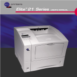
Use an RJ45 connector (10/100BaseT) or BNC connector (10Base2) to
connect to an Ethernet.
1.
2.
Turn off the printer.
Connect the connector to the NIC.
Feritecore
Tie band
10/100BaseT:
10Base2:
Plug an RJ45 connector into the Use a BNC T adapter to connect
10/100BaseT port on the back of to the BNC connector on the back
the NIC. Attach the ferrite core so of the NIC.
that it is near the connector. Next,
secure the ferrite core so that it
cannot move out of position using
the tie band.
3.
After you make the connection, perform the procedure under 2.2
Powering Up the Printer.
Note
• Use a Category 5 cable when connecting with a 10/100BaseT.
• Be sure to use a cable with a ferrite core when making a 10/
100BaseT connection.
2-2
Chapter
Utilizing Windows
Programs
3
Utilizing Windows Programs
Chapter 3
Utilizing Windows Programs
Chapter 3
The CD-ROM contains the following programs for the Windows
environment.
•
Discovery Program
•
Peer-to-Peer Printing Program
This program provides peer-to-peer printing capabilities, without
having to go through the server. Peer-to-peer printing can be enabled
by installing IP peer-to-peer printing under a TCP/IP environment, or
by installing IPX Peer-to-Peer printing program under an IPX/SPX
environment.
3-1
Utilizing Windows Programs
The Discovery Program generally utilizes the MAP (Management
Access Program) to find an IP or IPX based NIC. Once found, the
Discovery Program allows you to make setting changes through the
NIC’s built-in Web page.
Chapter 3
This program automatically searches for NICs on a network. Found
NICs are listed in the Web Browser being used. Clicking a NIC name
accesses the card’s onboard HTTP server, which you can use to make
various NIC settings. See Appendix C of this manual for details.
3.1 Discovery Program
Program –– Management
Management Access
AccessProgram
Program(MAP)
(MAP)
Utilizing Windows Programs
Chapter 3
3.1 Discovery Program – Management
Access Program (MAP) –
The Management Access Program (MAP) uses a Windows-based Web
Browser linked with a proprietary bi-directional IPX/IP channel
program to allow access to the NIC’s HTML-based monitoring and
maintenance capabilities. It is possible to search and manage IPX and
IP based printers with this program, however it is necessary to first
install TCP/IP, and preferably IPX/SPX protocols and a Web Browser
onto your PC. This program allows you to:
•
Configure your network protocols for the NIC.
•
Reset the NIC remotely to either clear an error condition, or return
the print server to its factory default settings.
•
Troubleshoot problems in the NIC.
•
Enable or disable the status report printout.
Note
• To be able to change parameter values with the MAP or the Web
Browser, you must know the NIC management password. The factory
default password is “sysadm”.
3.1.1 Installing the MAP
Use the following procedure for an automatic installation of the MAP.
If the opening screen does not appear as described in step 1, follow the
instructions for the manual installation procedure.
1. Insert the CD-ROM into your workstation’s CD-ROM drive. The
opening screen appears automatically.
2. Click the CD-ROM Contents button to display the Introduction
screen.
3. Click Installation/Configuration Programs located at the bottom
of the Introduction screen.
4. Select the program that you want to install and follow the instructions displayed on the screen.
3-2
3.1 Discovery
Discovery Program
Program––Management
ManagementAccess
AccessProgram
Program(MAP)
(MAP)
You can use the following procedure to manually install the MAP.
1. Insert the CD-ROM into your workstation’s CD-ROM drive.
2. Run the program. (In this example, we assume that drive D: is
your workstation’s CD-ROM drive.)
D:\Map\Setup.exe
3.
Follow the instructions that appear on the screen.
Chapter 3
The default installation directory is C:\Program Files\Map. You can
change to a different directory if you want.
3.1.2 Configuring the MAP
Click Start, point to Programs, and then point to MAP.
Click MAP Setup.
Utilizing Windows Programs
1.
2.
Search for IPX based printers:
Check this option to search for IPX/SPX based printers.
Search for IP based printers:
Check this option to search for TCP/IP based printers.
Max Hops for IP Search:
Type in a maximum hop value. The initial default value is 2.
3-3
3.1 Discovery Program
Program –– Management
Management Access
AccessProgram
Program(MAP)
(MAP)
Note
Utilizing Windows Programs
Chapter 3
• The maximum hop value defines the maximum number of subnetworks
the program will search to find a NIC. Setting a value 0 tells discovery
program to search only within the subnet to which the workstation is
connected. A hop value of 2 tells discovery program to search all networks accessible through as many as two routers. A value of 15 or
greater specifies automatic search of all connected networks, but this is
not recommended because of the amount of traffic it generates.
3.
After the settings are the way you want, click OK to set them and
close the dialog box.
3.1.3 Using the MAP
Use the following procedure to start up MAP and search for all
compatible NICs that are available on a network.
1. Click Start, point to Programs, and then point to MAP.
2. Click MAP.
A list of NICs found by the MAP search appears on the Web Browser
installed on the workstation.
To configure or reconfigure a particular NIC, click its serial number in
the Web Browser list.
Clicking a NIC serial number displays the Printer Management page of
the card’s onboard HTTP server. See Appendix C for details of how to
use this page to configure or reconfigure the NIC.
3-4
3.1 Discovery Program – Management
3.2 IP Peer-to-Peer
Access Printing
ProgramProgram
(MAP)
3.2 IP Peer-to-Peer Printing Program
This section describes how to set up and use the IP Peer-to-Peer
Printing program. With the setup procedure, you set up your print
server ports for printing from a Windows environment.
You can use the following procedure to manually install the IP Peer-toPeer Printing program.
1. Insert the CD-ROM into your workstation’s CD-ROM drive.
2. Run the program. (In this example, we assume that D: is drive
your workstation’s CD-ROM drive.)
D:\Ip-P2p\Setup.exe
3-5
Utilizing Windows Programs
Use the following procedure for automatic installation of the IP Peerto-Peer Printing Program. If the opening screen does not appear as
described in step 1, follow the instructions for the manual installation
procedure.
1. Insert the CD-ROM into your workstation’s CD-ROM drive. The
opening screen appears automatically.
2. Click the CD-ROM Contents button to display the Introduction
screen.
3. Click Installation/Configuration Programs located at the bottom
of the Introduction screen.
4. Select the program that you want to install and follow the instructions displayed on the screen.
Chapter 3
3.2.1 Installing the IP Peer-to-Peer Printing
Program
3.2 Discovery
3.1
IP Peer-to-Peer
Program
Printing
– Management
Program Access Program (MAP)
Follow the instructions that appear on the screen.
Utilizing Windows Programs
Chapter 3
3.
The default installation directory is C:\Program Files\IP-P2P. You can
change to a different directory if you want.
3.2.2 Setting Up IP Peer-to-Peer Printing
1.
2.
3.
3-6
Click Start, point to Programs, and then point to IP-P2P.
Click IP-P2P.
This displays the setup dialog box.
3.2 IP Peer-to-Peer Printing Program
Max Hops for Search:
Type in a maximum hop value. The initial default value is 2. See
the note under 3.1.2 Configuring the MAP for an explanation about
maximum hops.
IP Port Base:
This is the starting port number for the printserver. The default is
10000 (corresponding to a TCP/IP port of 10001) but you can
change it if you need to.
Based on Serial Numbers
Select this option to identify printers according to printer server
serial number. If SN991354 is the printer serial number, for example, SN991354 is the printer port.
Based on IP Address
Select this option to identify printers according to IP address. If
199.99.92.99 is the printer IP address, for example, 199.99.92.99 is
the printer port.
Based on DNS (Domain Name Server)
Select this option to identify printers according to DNS name.
Example:
<PTR-MKTG.DOMAIN.COM>.
Based on Unit Name
Select this option to identify printers according to unit name.
Example:
<MLT_999999>.
4.
After the settings are the way you want, click OK to set them and
close the dialog box.
3-7
Utilizing Windows Programs
These settings let you select what format to use when displaying
the printer list.
Chapter 3
Printer Names:
3.2 IP Peer-to-Peer Printing Program
3.2.3 Adding Printers for IP Peer-to-Peer
Printing
Utilizing Windows Programs
Chapter 3
The following steps can be used to manually add a printer that cannot be
found automatically due to router setup or the maximum hop count
setting. Note, however, that manual addition of printer is normally not
required.
Step 1:Use P2P-IP to make the printer an IP peer-to-peer printer.
1. Click Start, point to Programs, and then point to IP-P2P.
2. Click IP-P2P to display the Peer-to-Peer IP Setup dialog box.
3.
3-8
Click the Printers button to display a dialog box for input of a
new printer.
3.2 IP Peer-to-Peer Printing Program
4.
Click the Find Printers button to automatically search the network for a printer as well as to register it.
When registering a printer manually, enter the appropriate information for the following field descriptions and click the Add button.
Field Descriptions
IP Address:
Type in the name you want to assign to the printer. Assign a name
you feel best identifies the printer.
Port Number:
Type in the port number of the printer. The default port number setting is 10001.
Description:
5.
Type in text that describes the printer.
Click OK after you have finished adding all the printers you want.
Setp2: Installing the Printer Driver and Setting the Printer Port
1. Using the install program, install the printer driver that comes with
the printer.
Refer to the manual that came with the printer for details.
2. Open the Properties menu item of the printer icon.
3. Select the Detail tab.
4. Select the port that you want from the Print to the following port
item.
3-9
Utilizing Windows Programs
Name:
Chapter 3
Type in the IP address of the printer you want to add.
3.3 IPX Peer-to-Peer Printing Program
3.3 IPX Peer-to-Peer Printing Program
Utilizing Windows Programs
Chapter 3
The IPX Peer-to Peer Printing Program enables IPX Peer-to-Peer
printing in a Windows 95 or Windows NT 4.0 environment.
The following are the characteristics of IPX Peer-to-Peer printing.
•
IPX Peer-to-Peer printing implements peer-to-peer bi-directional
printing between Windows workstations and NIC printers.
•
The Peer-to-Peer implementation uses the IPX/SPX stacks that are
provided with Windows 95 or Windows NT4.0.
•
The IPX Peer-to-Peer Printing program establishes a connection
with the printers supporting Peer-to-Peer, without using an intermediate file server, whether or not your network uses Novell NetWare.
•
If you are not using NetWare, you do not need to activate any NetWare Client application.
Note
• The IPX Peer-to-Peer Printing program uses IPX/SPX Compatible Protocol, so you must install IPX/SPX Compatible Protocol on your workstation if it is not already installed. See the documentation that comes
with Windows for details about installation.
• Because Peer-to-Peer uses the IPX/SPX Protocol, Novell operation
must remain enabled on the NIC, even if traditional Novell printing
facilities are not being used. The name of the Peer-to-Peer printer, as it
appears in the Windows Port List, is the same as the Novell Print
Server name, and may be changed by changing the Novell Print Server
name using the Web-based management or MAP Program.
On power up, the NIC checks the network to see if there is Novell
activity. If there is, it will use the same frame type and the local
network number that it senses. If, in addition, the NIC can log on to a
file server, it will assume that Novell is normally used and will store
this frame type and new number in NVRAM so that, when it comes up
again, it will not have to spend the time sensing (which can take some
time). However, if the NIC cannot attach to a file server, it will use the
sensed values, but will not store them.
3-10
3.3 IPX Peer-to-Peer Printing Program
If the NIC does not see any Novell activity, it will use 802.2 on 802.3
as a frame type and will assign itself a network number of 0. The frame
type and network number being used is shown on the status report.
Note
Use the following procedure for an automatic installation of the IPX
Peer-to Peer printing Program. If the opening screen does not appear as
described in step 1, follow the instructions for the manual installation
procedure.
1. Insert the CD-ROM into your workstation’s CD-ROM drive. The
opening screen appears automatically.
2. Click the CD-ROM Contents button to display the Introduction
screen.
3. Click Installation/Configuration Programs located at the bottom
of the Introduction screen.
4. Select the program that you want to install and follow the instructions displayed on the screen.
You can use the following procedure to manually install the IPX Peerto-Peer Printing program.
1. Insert the CD-ROM into your workstation’s CD-ROM drive.
2. Run the program. (In this example, we assume that drive D: is
your workstation’s CD-ROM drive.)
D:\Ipx-P2p\Setup.exe
3. Follow the instructions that appear on the screen.
Once the redirector is installed, each printer on the network that supports this Peer-to-Peer capability will appear as a Port under Printer. To
use the Peer-to-Peer connection, create a logical printer using the
driver installation program according to the instructions for your
printer. Set up the printer as a LOCAL printer.
3-11
Utilizing Windows Programs
3.3.1 Installing the IPX Peer-to-Peer Printing
Program
Chapter 3
• If a NIC is being moved from a site that had active Novell to a site that
does not, the unit should be reset to the factory default to clear the
frame type and network number information.
3.3 IPX Peer-to-Peer Printing Program
3.3.2 Installing the Printer Driver and Setting
the Printer Port
1.
Utilizing Windows Programs
Chapter 3
2.
3.
4.
Using the install program, install the printer driver that comes with
the printer.
Refer to the manual that came with the printer for details.
Open the Properties menu item of the printer icon.
Select the Detail tab.
Select the port that you want from the Print to the following port
item.
3-12
3.4 Using a Web Browser
3.4 Using a Web Browser
Utilizing Windows Programs
Chapter 3
Once you have assigned an IP address to your NIC, you can use a Web
browser such as Netscape Navigator or Microsoft Internet Explorer to
access the NIC’s onboard HTTP server. The HTTP server can be used
to perform various maintenance procedures. See Appendix C of this
manual for details.
3-13
Utilizing Windows Programs
Chapter 3
3.4 Using a Web Browser
3-14
Chapter
NetWare Configuration
4
NetWare Configuration
Chapter 4
NetWare Configuration
Chapter 4
4.1 Configuring NetWare 2.15 and 3.x
Use this chapter if you will be printing from Novell NetWare. This
chapter is divided into the following sections:
•
Configuring NetWare 2.15 and 3.x describes how to configure
the NIC for use with Versions 2.15 or 3.x. Use PCONSOLE to set
up the print server function.
•
Configuring NetWare 4.x in Bindery Emulation describes how
to configure the NIC for use with Version 4.x —Bindery Services.
Use PCONSOLE to set up the print server function.
•
Configuring Novell Directory Services describes how to config-
ure the NIC for use with Version 4.x Directory Services. Use
NWADMIN to set up the print server function.
MAP or a Web Browser used to configure the Print Server for NetWare.
•
Using NetWare Utilities explains how to use standard Novell NetWare utilities to make changes to the configuration of the Print
Server function.
4.1 Configuring NetWare 2.15 and 3.x
Before configuring NetWare, you must determine if the NIC has its
desired name. Use MAP or a Web Browser to change the name if you
want. Refer to section 3.1 for this setting.
The following steps are the general procedures for configuring the
NIC, which require supervisor privileges. These steps are covered in
detail in the following paragraphs:
1. Start PCONSOLE and select the file server you want to use.
2. Create the print queues.
3. Specify the NIC as a print server.
4. Configure the print server and printer.
5. Assign the print queues.
6. Set up the NOTIFY options.
7. Repeat the procedure for other file servers.
4-1
Chapter 4
NIC Setup Parameters describes the parameters accessible via
NetWare Configuration
•
4.1 Configuring NetWare 2.15 and 3.x
When you are finished, turn the printer off and on again. The printer
creates a status report that indicates the file servers to which the unit is
attached and the queues which it services.
Before you begin:
•
Verify that you have supervisor privileges on the file servers on
which the NIC print server is to be entered.
•
Verify that your version of PCONSOLE is later than 1.0.
NetWare Configuration
Chapter 4
4.1.1 Start PCONSOLE and Select File Server
Follow these steps to start PCONSOLE:
1. Log in to the network, type PCONSOLE and press Enter .
2. Choose Change Current File Server from the Available Options
menu. This displays a list of file servers.
3. Select the file server on which you want to install the print server
and press Enter . If the name of the file server you want is not displayed, press Insert to get a list of file servers.
4. Log in to the file server.
5. Press Esc to return to the Available Options menu.
4.1.2 Create Print Queues
The NIC must be assigned to at least one print queue on the file server.
•
If the print queue that you want the NIC to service already exists,
and you know the name of this queue, go to 4.1.3 Enter the Print
Server Name.
•
If you do not know the name of the queue, or it does not exist, use
the following procedure:
Choose Print Queue Information from the Available Options
menu, and press Enter . This displays a list of existing queues.
To create a new queue, press Insert . Type the name of the queue
and press Enter . You do not need to enter any more information at
this time.
Press Esc to return to the Available Options menu.
1.
2.
3.
4-2
4.1 Configuring NetWare 2.15 and 3.x
4.1.3 Enter the Print Server Name
3.
Type the name of the print server into the entry box. The Novell
print server name is printed under Novell NetWare information on
the status report.
Note
• If desired, this name can be changed using MAP or Web Browser. The
screen example shows how to enter the print server name for a print
server with a serial number of MLT_160151.
4.
Press
Enter
to add the print server name to the Print Servers list.
4-3
NetWare Configuration
Chapter 4
A print server takes the print jobs from queues and sends them to the
printer. Use this procedure to specify the name of the print server:
1. Choose Print Server Information from the Available Options
menu, and press Enter . This displays a list of existing print servers.
2. press Insert . The New Print Server Name box is displayed.
4.1 Configuring NetWare 2.15 and 3.x
4.1.4 Configure the Print Server
NetWare Configuration
Chapter 4
Use the following procedure to configure the Print Server’s function:
1. Choose the print server name from the Print Servers list and press
Enter .
The Print Server Information menu appears.
2. Choose Print Server Configuration from the menu and press Enter .
3. Choose Printer Configuration from the menu and press Enter .
This displays the Configured Printers menu. Since this is a new
Print Server entry, all printers are labeled “Not Installed”.
4. Choose the printer and press Enter . The Printer 0 Configuration
screen appears with a title of Printer 0, as shown in the following
example.
5.
6.
7.
4-4
If you choose to, change the default in the Name field on this form
to MFP or something else that helps you identify the printer. The
print server uses this name in its message back to the users on the
Notify list. Select Name, enter a name, and then press Enter .
Select Type and press Enter . This displays a list of printer types.
Choose Remote Other/Unknown and press Enter . This creates
default entries in the other fields. These defaults are usually optimal, so do not change them without specific knowledge of the
effects.
Press Esc . At the prompt, choose to save your changes.
4.1 Configuring NetWare 2.15 and 3.x
8.
Press
Esc
to return to the Print Server Configuration menu.
4.1.5 Assign Print Queues to the Printer
When you assign queues to the defined printer, you authorize the print
server to service these queues.
Note
• Do not assign the same queue to two different print servers. If a queue
is assigned to multiple print servers, print jobs may not go to the
intended printer.
Choose Queues Serviced By Printer from the Print Server Configuration menu.
2.
3.
Select the printer name from the list of defined printers.
Press Insert to display the Available Queues list for the printer.
NetWare Configuration
Chapter 4
1.
4-5
4.1 Configuring NetWare 2.15 and 3.x
NetWare Configuration
Chapter 4
4.
5.
Select the queue you want and then assign a priority level from 1
to 10. It is recommended that you accept the default priority level.
Press Enter . The queue appears on the list for the printer.
Press Insert again to assign additional queues.
When you finish assigning queues, press Esc and then save your
changes. Continue to press Esc to return to the Print Server
Configuration menu. If you want to set Notify options, go to Section. 4.1.6. If you are finished, continue to press Esc and then
save your changes.
4.1.6 Set Up Notify Options for the Printer
(Optional)
To enable the print server to notify users or user groups if a problem
occurs with the printer, set up the Notify options. The print server
supports the enhanced NOTIFY options for printers, including
informing users when the printer:
•
Is off-line, jammed, opened, or out of paper
•
Requires a manual paper feed or a form change
•
1.
Has had an engine failure
Choose Notify List for Printer on the Print Server Configuration
menu.
4-6
4.1 Configuring NetWare 2.15 and 3.x
4.
5.
Insert
to
Set the First and Next intervals in the Notify Intervals screen. It is
recommended that you use the defaults. The First interval is the
number of seconds the network waits before it notifies candidates
about a print job problem. The Next interval specifies how often in
seconds candidates are notified. Enter a number for each interval
and press Enter .
Press Esc and then choose Save Changes. Press Esc at each
screen until you reach the Print Server Configuration menu. After
you have finished the configuration, press Esc and then save the
changes.
4-7
Chapter 4
3.
Select the printer from the Defined Printers list. Press
view a list of Notify Candidates.
Select the user or group from the list.
NetWare Configuration
2.
4.1 Configuring NetWare 2.15 and 3.x
4.1.7 Installing the Print Server on Multiple
File Servers
NetWare Configuration
Chapter 4
To install the print server on more than one file server, perform the
procedures described in Sections 4.1.1 through 4.1.6 for each file
server. You must use the same name and password for the print server
(or no password) on all file servers. You set the password for the NIC
using the MAP or a Web Browser (refer to 4.3 Configuring the NIC in
Novell Directory Services). If you use a password, specify it on each
file server using the Change Password option on the Print Server
Information menu of the PCONSOLE utility.
When the NIC comes up, it automatically searches for and attaches to
the file servers that are no more than four hops and have no more than
eight ticks propagation delay. For extremely large or complex
networks, this allows a bounded search time on start-up. If the print
server must attach to file servers beyond this range, or, if you wish to
accelerate start-up by eliminating the need to search all file servers in
the four hops/eight ticks radius, the file servers with which the print
server is to operate may be entered into the Print Server Configuration
of a “primary” file server. The primary file server can be any file server
within the four hops/eight ticks propagation time limits, but ideally is
as close as possible to the print server. Once the print server locates the
primary file server and the list of file servers to be serviced, the
automatic search is dropped and the print server will go directly to
those file servers listed (and to no others).
4-8
4.1 Configuring NetWare 2.15 and 3.x
4.1.8 Primary File Server
To use the primary file server option, use the following procedure on a
file server close to the printer:
1. List the file servers to be serviced by the primary file server by
selecting File Server To Be Serviced option from the Print
Server Configuration Menu.
2. Press Insert to display the Available File Servers list.
3. Select the name if each file server to be serviced and press Enter to
add it to the File Servers To Be Serviced list.
4. When the list is complete, press Esc to return to the menu.
5. Install the NIC on each of the primary file servers.
Note
• The Preferred File Server is only applicable to bindery-based queues.
Entering it has no affect on NDS queues.
4-9
NetWare Configuration
The Management Access Program MAP or Web Browser allow you to
identify a “preferred” file server, to be identified within the NIC itself.
If a preferred file server is listed, the NIC will attach to this identified
file server instead of initiating the automatic search. If the preferred file
server is also a primary file server (for example, has file servers listed
under file servers to be serviced), the NIC will connect directly to these
file servers.
Chapter 4
4.1.9 Preferred File Servers
4.2 Configuring NetWare 4.x — Bindery Emulation
4.2 Configuring NetWare 4.x — Bindery
Emulation
Novell’s NetWare 4.x can operate in two modes — Novell Directory
Services (NDS) and Bindery Services Emulation. For Directory
Services, see 4.3 Configuring the NIC in Novell Directory Services.
These services run simultaneously and transparently to each other. The
NIC may be configured to operate with Bindery Services mode only
(this section), or to operate under NDS (4.3 Configuring the NIC in
Novell Directory Services). When configured under NDS, the NIC will
also service older file servers operating in bindery mode.
NetWare Configuration
Chapter 4
Note
• If the NIC is not properly set up for NDS and the Bindery Services
mode is not running, the NIC can not find its file servers, and the status
report indicates the Novell NetWare protocol is not active.
4.2.1 Confirm Bindery Context
Before installing the NIC on a Novell NetWare 4.x server in Bindery
Emulation mode, check that the server has a Bindery Context (name
for the server under Bindery Services mode). If the server does not
have Bindery Context, it may be preferable to install in NDS mode. If
the NIC must be installed in the Bindery Emulation mode, the server
must have Bindery Context. Perform the following steps to confirm the
server has Bindery Context:
1. Go to the 4.x server and at the system console type: load install
2. Select Maintenance/Selective Install from the menu.
3. Select NCF Files Options from the menu.
4. Select Edit AUTOEXEC.NCF from the menu.
5. Search the file to see if you have a statement similar to the following included:
6.
SET BINDERY CONTEXT=OU=ENG
Where =OU=ENG is an example of a name for the file server context. Use your own file server context in place of =OU=ENG.
At the console prompt, type the SET BINDERY CONTEXT state-
ment that you entered in the autoexec.ncf file.
4-10
4.2 Configuring NetWare 4.x — Bindery Emulation
Note
• The command at the console prompt takes effect immediately. The definition in the autoexec.ncf file takes effect when the server is shut
down and then restarted.
4.2.2 Configure in Bindery Mode with
PCONSOLE
Once you confirm the server has Bindery Context, use the following
procedure to configure the NIC.
1. Log into the network as ADMIN.
2. Type PCONSOLE and press Enter . The following screen appears.
Print Queues
Printers
Print Drivers
Quick Setup
Change Context
3.
When the Available Options menu appears, press
Bindery Mode).
F4
(for the
Note
• If you receive a message asking you to login to a server with Bindery
connections, the server you are attached to does not have Bindery
Mode enabled. Follow the procedures in 4.2.1 Confirm Bindery Context or log onto a server with Bindery Services activated.
4.
From the Available Options screen, select Quick Setup and press
Enter .
4-11
NetWare Configuration
Chapter 4
Available Options
4.2 Configuring NetWare 4.x — Bindery Emulation
NetWare Configuration
Chapter 4
Use Quick Setup to connect your print server, print queue and
printer correctly. You can modify these later if you need to.
5.
6.
Select Print server and press F3 to modify the entry.
Type the name of the print server in the Print server field and
press Enter .
Note
• The print server name is printed under the Novell Network Information
on the status report. The factory default name is MLT_<serial number>.
7.
Press
to move to the New printer field. Type a name and press
Enter .
8. Press
to move to the New print queue field. Type a name and
Enter
press
.
9. Press
to move to the Printer type field and press Enter . From
the list of printer types, select Other/Unknown and press Enter .
10. When you are finished, press F10 to save the configuration.
Repeat steps 5 through 10 for each file server that the printer
server services.
11. To view, add, delete, or modify print servers or queues after the
initial setup, select either the Print Queues or Print Servers
option on the Available Options screen.
4-12
4.3 Configuring the NIC in NetWare
4.3 Configuring the NIC in Novell Directory
Directory Services
Services
The Directory Information Base (DIB) is used to store information
about servers and services, users, printers, gateways, etc. It is a
distributed database, allowing access to data anywhere on the network
wherever it is stored. Pre-4.x NetWare versions provide the same data
found in the DIB but the data is stored in the NetWare Bindery. The
DIB was designed with more flexible access, more specific security,
and, since it is distributed, it was designed to be partitioned. The
Directory uses an object-oriented structure rather than the flat-file
structure of the Bindery, and offers network-oriented access, rather
than server-oriented access found in the Bindery.
The Directory is backward-compatible with the NetWare Bindery
through Bindery emulation mode. Section 4.2 describes Print Server
Operation with a 4.x NetWare system in bindery emulation mode.
When Bindery emulation is enabled, Directory Services will accept
Bindery requests and respond just as if a Bindery existed on the
NetWare server being accessed. Be aware that information obtained
from the Bindery query may not be stored in the server since the
Directory is a partitioned and distributed database. Even though the
NetWare 4.x server is not operating from a Bindery, the applications
making Bindery requests will not know the difference.
4-13
NetWare Configuration
Novell Directory Services (NDS) offers a different, more advanced
approach to network management than previous NetWare versions.
Generally, it stores and tracks all network objects. As a rule, all 4.x
servers must have NDS loaded in order to function. In this way, every
NetWare 4.x server is a Directory server, because it services named
Directory objects such as printers, print servers and print queues. With
the appropriate privileges, you can create a print server object, which,
once configured in its context (or location) on the network, eliminates
the cumbersome setup of print servers on every network server. NDS
provides true enterprise networking based on a shared network
database rather than a individually defined physical sites. The result is
greatly improved print server setup and management.
Chapter 4
4.3 Configuring the NIC in Novell
Directory Services
4.3 Configuring the NIC in NetWare
4.3 Directory
Configuring
the NIC in Novell Directory Services
Services
NetWare Configuration
Chapter 4
You may use NWADMIN to configure the printer in NDS. Prior to
printing, NDS must be set up as follows and the NIC must be set up
with NDS Context and Tree. See Section 4.4. The steps below describe
the use of NWADMIN configuration to create printer, print server, and
print queue objects. Then, you will assign, or associate those objects
with each other. If you wish to keep Bindery resources on any server,
you can under NetWare 4.x if you declare a SET statement in your
AUTOEXEC.NCF file.
For those who prefer, NetWare does offer PCONSOLE as an
alternative to NWADMIN. PCONSOLE can be used to set up static
information about print servers such as: which queues to service, and
whom to notify in the event of a problem. See Novell NetWare
documentation for more information about the use of PCONSOLE for
NDS.
4.3.1 Create Printer Object
1.
2.
Click on the NWADMIN icon in the NetWare Tools group in Windows. The NetWare Administrator window will appear. To bring
up your Directory Tree, open a Browser window by clicking on
the Tools menu item and, the Browse item.
Highlight the Organizational Unit or Organization where you want
to create the print service in the Directory Tree, select the Object
item from the main menu and choose Create...
Note
• If you wish, you can create objects another way in NWADMIN by:
selecting an Organizational Unit, clicking on the right mouse button
(which produces a pop-up menu), and clicking on Create... use the left
mouse button to bring up the New Object window). From this point,
the procedure continues as described.
4-14
4.3 Configuring the NIC in NetWare
4.3 Configuring the NIC in Novell Directory
Directory Services
Services
When the New Object window appears, scroll down the Class of
New Object icon list, select the Printer icon and click on the OK
button.
4.
When the Create Printer window appears, type a value in the
Printer Name field and click on the Create button.
4.3.2 Create Print Server Object
1.
2.
3.
Again, highlight the Organizational Unit, select the Object item
from the menu and choose Create...
At the New Object window, scroll down the Class of New Object
icon list, select the Print Server icon, and click on the OK button.
At the Create Print Server window, type a value in the Print
Server Name field and click on the Create button.
4-15
NetWare Configuration
Chapter 4
3.
4.3 Configuring the NIC in NetWare
4.3 Directory
Configuring
the NIC in Novell Directory Services
Services
4.3.3 Create Print Queue Object
1.
2.
NetWare Configuration
Chapter 4
3.
Once again, highlight the Organizational Unit, select the Object
item from the menu and choose Create...
At the New Object window, scroll down the Class of New Object
icon list, select the Print Queue icon, and click on the OK button.
At the Create Print Queue screen, click on the Directory Service
Queue button, then type in values for Print Queue Name and
Print Queue Volume and click on the Create button. If you don’t
know the Print Queue Volume name (the hard drive you will be
accessing), click on the icon to the right of the volume field. The
Select Object window will appear with the volume listed in
Objects. If the volume is not listed, scroll the Directory Context
items until you find the volume where you want the queue to
reside.
4-16
4.3 Configuring the NIC in NetWare
4.3 Configuring the NIC in Novell Directory
Directory Services
Services
4.3.4 Assign Printer Object
1.
Go to the Directory Tree. Double click on the printer object just
created and bring up the Printer window. See below. Find the
Assignments button on the right-side of the window and click on
the Add button.
4-17
NetWare Configuration
Chapter 4
Click on the object (hard drive) of your choice and it will appear in the
Selected Object: field. Click on the OK button. The full volume will
now appear in the Print Queue Volume field. Finally, click on the
Create button.
4.3 Configuring the NIC in NetWare
4.3 Directory
Configuring
the NIC in Novell Directory Services
Services
When the Select Object window appears, find the print queue
object just created among the choices listed in the Objects box
and select it.
NetWare Configuration
Chapter 4
2.
Click on the OK button and the print queue just created is added to
the Print Queues: box in the Printer: window. Click on the OK
button again.
4-18
4.3 Configuring the NIC in NetWare
4.3 Configuring the NIC in Novell Directory
Directory Services
Services
4.3.5 Assign Print Server Object
At the Directory Tree, double click on the print server object you
just created and bring up the Print Server window.
2.
At the Print Server: window, click on the Assignments button
and Add button to bring up the Select Object window. Select the
printer object just created from the Objects: box and click on the
OK button. Now the printer (with its context) appears in the Printers: box of the Print Server window. Click on the OK button.
4-19
NetWare Configuration
Chapter 4
1.
4.3 Configuring the NIC in NetWare
4.3 Directory
Configuring
the NIC in Novell Directory Services
Services
4.3.6 Check Assignments
NetWare Configuration
Chapter 4
At the Directory Tree, double click on the Print Queue object you just
created. At the Print Queue window, click on the Assignments button.
If you configured the print queue and printer correctly they will appear
in the proper boxes on the Print Queue window. Press the Cancel
button.
4-20
4.3 Configuring the NIC in NetWare
4.3 Configuring the NIC in Novell Directory
Directory Services
Services
4.3.7 Set Up and Reset the Printer
NetWare Configuration
Chapter 4
NWADMIN configuration is complete. Before you can begin printing,
though, be sure to set up and reset (power cycle) the printer.
4-21
4.4 NIC Configuration
4.4 NIC Configuration
NetWare Configuration
Chapter 4
The MAP or a Web Browser must be used to define the context and
tree of the Print Server. It is also used to change the Print Server name,
set in a password, modify scan and frame search parameters, and sent
in bindery-mode specific values.
Use the MAP or Web Browser (refer to Chapter 3) to access the Setup
pages of the NIC. Once you have accessed the Network Setting pages
or the Main Menu, do the following:
1. Select Setup NetWare under Protocols.
2. Click on Enable NetWare. If it is not selected, the NetWare protocols will not come up, the NIC will not appear as an advertised
device, and the NIC will not be accessible using IPX SNMP.
3. The default name for the NetWare Print Server is MLT_123456,
123456 is the serial number of the NIC. This is also the name of
the printer in peer-to-peer mode. If you want to change the default
Print Server name, type this name in the Print Server Name
space. Leave the space blank if the default name is to be used.
4. If you want the NIC login with a password, this password may be
entered in the Print Server Password field, and again in the
Password Retype field. If a password is used, this password must
be the same password for all bindery-based and NDS-based Print
Server entries.
5. Type the name of a preferred bindery-based file server in the Preferred File Server field. The Preferred File Server entry is significant only for bindery or bindery emulation based operations. Refer
to 4.1.9 Preferred File Servers for the significance of a Preferred
File Server. The Print Server must be configures on the Preferred
File Server. Incorrect setup of a Preferred File Server can interfere
with NetWare printing.
4-22
4.4 NIC Configuration
6.
If the Print Server is to be operated under Novell Directory Services, type in a Context entry and Preferred NDS Tree entry in
the appropriate fields. Be sure to give the whole context, whether
typed or typeless, and do not begin your context path with a trailing period (.). If you don’t know your tree, type: whoami at the
DOS command line. A typed context name example is:
ou=standard.ou=organization_1
4-23
NetWare Configuration
In the default mode, the Print Server scans each queue which it is
to service once per second. If you prefer a longer scan rate, you
may enter the time between scans in seconds in the Print Queue
Scan Rate field.
8. The NIC will normally monitor the network to determine which
frame type is being used for NetWare. When it recognizes a type,
it will assume the same frame type. Once it selects a frame type,
the NIC will only operate over that NetWare frame type. Monitoring normally starts looking for IEEE 802.3, then Ethernet II, then
802.3 SNAP, etc. If your network is using multiple frame types for
NetWare, you should bias the frame search to the desired type by
setting the button next to the designation under Ethernet Frame
Type.
9. You can Disable Bindery mode on the Print Server if you are
operating in NDS mode only. To do so, click on that box. If you
disable Bindery, the NIC will not support Print Servers on a Bindery file server.
10. Once you have selected all desired settings and entered the desired
NetWare information, you may cause this information to be
entered in the NIC NVRAM by clicking on Accept Settings. As
with all value changes, if you have not entered the NIC Management Password before, you must enter it in the appropriate space
before clicking on Accept Settings.
11. Entered values do not take effect until the NIC is reset or power
cycled. You may reset from MAP or the Web Browser by returning to the Network Settings page, and click on Reset under System. Now click on Reset Unit. Alternatively, you may power
cycle the printer. The new NetWare values should now be in
effect.
Chapter 4
7.
4.5 Using the Novell PCONSOLE Utility
4.5 Using the Novell PCONSOLE Utility
This section explains how to use the PCONSOLE utility to perform the
following tasks:
•
Attach and select a file server
•
Select or delete queues for the print server
•
Set-up the Notify function
See the NetWare Print Server Manual for detailed information on this
utility.
Note
NetWare Configuration
Chapter 4
• You must have Supervisor privileges to perform many PCONSOLE
operations.
4.5.1 Changing the File Server
You can specify a file server as the current one. To change the file
server, use the following procedure:
1. Log into the current file server and start the PCONSOLE utility.
2. Select Change Current File Server from the Available Options
menu.
3. Press Insert to display the available file servers.
4. Select the file server you want as the current one and press Enter .
5. Type your username and press Enter . If the username requires a
password, the Password screen is displayed. Type the password
and press Enter .
6. Select Change Current File Server from the Available Options
menu. A list of the attached file servers is displayed.
7. Select the current file server from the File Server/Username
screen.
4-24
4.5 Using the Novell PCONSOLE Utility
4.5.3 How to Set Up Notify
You can specify users or groups of users that are notified if a problem
occurs when a print job is sent to the printer. If the print server is
servicing queues on multiple file servers, you must set up a NOTIFY
list for each file server. To set up NOTIFY, use the following
procedure:
1. Start the PCONSOLE utility.
2. Select Print Server Information from the Available Options menu.
3. Select the print server from the menu.
4. Select Print Server Configuration from the menu.
4-25
NetWare Configuration
When you print a file, your system sends the file to a print queue. The
print server assigned to that queue extracts the print job and sends it to
the assigned printer. If a print server is servicing queues on multiple
file servers, you must assign queues to the printer on each file server.
To change the print queues, use the following procedure:
1. Start the PCONSOLE utility.
2. Select Print Server Information from the Available Options
menu.
3. Select the print server from the list.
4. Select Print Server Configuration from the menu.
5. Select Queues Serviced by Printer from the menu.
6. Select a printer from the Defined Printers list.
7. Press Insert at the File Server/Queue/Priority screen. The Available Queues list appears.
8. Select a queue from the list.
9. Press Enter at the Priority screen to leave the priority setting at 1.
The highest priority is 1; 10 is the last. To change the priority of a
queue, press Enter at the File Server/Queue/Priority screen to disto delete the current setplay the Priority setting screen. Press
ting. Type a new number from 1 to 10 and press Enter .
Repeat steps 7, 8, and 9 to assign additional queues to the printer.
10. Press Esc and save all changes.
Chapter 4
4.5.2 Changing Print Queues
4.5 Using the Novell PCONSOLE Utility
Select Notify List for Printer from the menu.
Select the printer from the Defined Printers menu.
Press Esc at the File Server/Notify Name/Notify Type/First/
Next screen. The Notify Candidates screen appears.
8. Select the user or user group from the Notify Candidates screen.
The Notify Intervals screen displays.
9. Set the First and Next intervals for notifying users about printer
problems. The First interval is the number of seconds the network
waits before it notifies users about a print job problem. The Next
interval specifies how often in seconds users are notified. Enter a
number for each interval and press Enter .
10. Press Esc and save all changes.
11. Press Esc until you see the prompt to exit PCONSOLE. Select
Yes and then press Enter .
NetWare Configuration
Chapter 4
5.
6.
7.
4-26
Chapter
AppleTalk Configuration
5
AppleTalk Configuration
Chapter 5
AppleTalk Configuration
Chapter 5
5.1 Choosing the Printer
Use this chapter if you will be printing from a Macintosh. This chapter
explains how to configure the NIC using AppleTalk and how to use the
AppleTalk NIManage utility program.
Note
• The printer must be equipped with the PS option when operating in an
AppleTalk environment.
Note
• The Chooser screen will not show AppleTalk zones if your network
does not have more than one zone.
8.
9.
Select the AppleTalk Zone containing the printer from the list at
the lower left of the screen. Select the device driver type corresponding to your printer from those indicated at the upper left of
the screen. A list of printers will appear in the display panel at the
right of the screen.
From the display panel at the right of the screen, choose the name
of the printer from the list of printers. The AppleTalk printer name
for your printer is printed out on the status report under AppleTalk
Connection Information.
5-1
AppleTalk Configuration
To choose the printer, use the following procedure:
1. Make sure you have loaded the printer driver appropriate to your
printer.
2. Select the AppleTalk link for AppleTalk by clicking on the Apple
icon in the Macintosh menu bar.
3. Select Control Panel.
4. Click on Apple Talk.
5. Choose AppleTalk as the AppleTalk connection.
6. Click on the Apple menu.
7. Select Chooser to display the Chooser screen.
Chapter 5
5.1 Choosing the Printer
5.2 Loading the AppleTalk NIManage Utility Program
10. The options available at this point depend on your printer driver.
With a typical driver, you may select SETUP. Then select AUTO
SETUP. There will be a series of messages as the Chooser communicates with the printer and locates the proper PPD. The setup
screen will return, listing the PPD file selected. Select OK. Then
exit from Chooser.
5.2 Loading the AppleTalk NIManage
Utility Program
AppleTalk Configuration
Chapter 5
The AppleTalk NIManage utility program has the following functions:
•
View the names of the printer or printer zone.
•
Enable or disable the status report.
•
View the error log.
•
Enable or disable other protocols and view or modify the TCP/IP
address, subnet mask, and default gateway address.
Use the following procedure to get access to AppleTalk NIManage
utility program:
1. Insert the CD-ROM into the CD-ROM drive.
2. Double-click the NIC mac icon from the CD-ROM.
3. Click the CD-ROM Contents button to display the Introduction
screen.
4. Click Installation/Configuration Program located at the bottom
of the Introduction screen.
5. Select the NIManage AppleTalk Administration Program item
to start the NIManage program. The Zone and Device screen is
displayed.
5-2
5.2 Loading the AppleTalk NIManage Utility Program
You can use the following procedure to start the NIManage program
instead of step 1 to 5 above.
Insert the CD-ROM into the CD-ROM drive, and double-click the
APPLTLK folder from the CD-ROM. Double-click the NIManage
icon
•
The Zone and Device screen appears on the display.
Chapter 5
•
• If you have one zone, the above screen will not appear.
6.
From the Device display panel, select the NIC. After you select
the device, a menu of options is added to the menu bar at the top of
your screen.
5-3
AppleTalk Configuration
Note
5.3 Configuring the NIC
5.3 Configuring the NIC
You use the options added to the menu bar to configure the print server.
Depending on your printer, certain operations may not be available.
These functions will be “grayed” out and cannot be selected.
5.3.1 Configuration
Use the Configuration function to change the names of the device and
AppleTalk Zone.
AppleTalk Configuration
Chapter 5
5.3.2 Error Log
The Error Log function is used to view a log of events that the NIC has
registered. The log contains information as well as errors. Customer
Support may need the information on this screen if your NIC
encounters problems.
Choosing this function displays a screen containing the text of the log.
You can print the error log contents by using the Print option under the
File menu. To save the contents of the error log, do one of the following:
•
Use the Save As option from the File menu to save the entire log
file.
•
Use the Edit option to cut, copy, and paste some or all of the log
file.
Note
• This does not enter data into the error log itself. The data is cleared
each time the printer is power cycled.
5-4
5.3 Configuring the NIC
5.3.3 Protocol Setup
Use the Protocol Setup option to configure network protocols other
than AppleTalk. Selecting the Protocol Setup function displays the
following screen:
1.
2.
3.
4.
Click the protocols to On if you want them to be active. Click
those protocols that you do not want to use to Off. The utility will
not let you make active any protocol that the NIC does not support
or cannot handle because of active protocol limitations.
Type the IP address and subnet mask if you have enabled TCP/IP.
Type the default gateway address, if you have one.
Click on OK when you have finished using this screen.
You must power the printer off and on to make the changes take
effect.
5.3.4 Options
Click on Status Sheets: Enable to send a status report to the printer
each time you power it on, or click on Disable to disable this option.
Click on OK. The change takes effect the next time you power on the
printer.
5-5
AppleTalk Configuration
• The default values for the IP address and Subnet Mask are shown as
zeros. However, this represents a “no IP address” condition, not an IP
address.
Chapter 5
Note
AppleTalk Configuration
Chapter 5
MEMO
Chapter
TCP/IP Configuration
6
TCP/IP Configuration
Chapter 6
TCP/IP Configuration
Chapter 6
6.1 Installation in a Windows Environment
This chapter explains how to configure the NIC and your network for
use with TCP/IP communication in various environments. Independent
setup and installation procedures are provided for Windows systems
and for most popular UNIX systems. The NIC TCP/IP capability will
also operate with lpr spoolers on other systems, and with spooler/
supervisor capabilities that communicate raw print jobs to the Print
Server TCP/IP Port. This port number defaults to 10001, but may be
changed to any desired number using the Telnet utility, SNMP, or the
HTML pages accessible via MAP or a Web Browser. Section 6.3
Running Telnet, describes the interactive setup capability accessible
through the Telnet utility on any TCP/IP platform, and is equally
applicable to Windows, UNIX, and other TCP/IP environments. The
use of MAP or a Web Browser to access Web pages in the NIC is
described in Chapter 3.
6-1
TCP/IP Configuration
The several versions and variations of Microsoft Windows may be
used on a NetWare and/or TCP/IP networks, as well as in a native
Microsoft Windows network. This flexibility allows various options
for setting up the network printing system even though this NIC does
not support NetBEUI. If the Windows workstations are connected to a
NetWare network, configure the printer interfaces for NetWare, and
use standard Windows/NetWare utilities to provide access to the
printer. If NetWare is not to be used, the users may access the printer
using TCP/IP. Windows 95 and Windows NT4.0 users can also use the
NIC Peer-to-Peer capability as described in Chapter 3. The following
sections describe installation using TCP/IP under Windows for
Workgroups, Windows 95, and Windows NT.
Chapter 6
6.1 Installation in a Windows Environment
6.1 Installation in a Windows Environment
Note
• See the documentation that comes with Windows for details about
installing TCP/IP on each workstation.
• Printing with TCP/IP requires that the workstation have TCP/IP capability and the corresponding spooler, lpr; or that the workstation can
share an lpr queue on a Windows NT server (for example) that has one.
In general, if printers are not shared, an lpr queue must be created on
each workstation from which printing is initiated. See the Windows
documentation about sharing printers.
Windows for Workgroups
Windows for Workgroups does not normally come with TCP/IP.
However, various TCP/IP facilities are available for Windows for
Workgroups workstations, including a free TCP/ IP provided by
Microsoft. There are third party lpr spoolers available. The following instructions are based on the Microsoft TCP/IP and a shareware lpr application that is available from various sources. You
will need the files WFWTCP32.zip and WFWTCP32.txt for the
TCP/IP, and Windows lpr Spooler Version 4.1 (wlprs41.zip and
wlprspl.txt) for the lpr.
Chapter 6
See the file named wlprspl.txt for details about installing Windows lpr Spooler Version 4.1.
If you wish to use the BOOTP, you also need the BOOTPL16.exe
file provided with this NIC.
Windows 95
TCP/IP Configuration
Windows 95 comes with a TCP/IP stack. To print with this protocol, a client also requires an lpr utility. This program is available
from various sources. The lpr queue can be created on each workstation or the lpr queue can be created on one workstation and
shared on the network. Windows 95 workstations can also share an
lpr printer installed on a Windows NT server on the network.
The following instructions are based on the a shareware lpr application that is available from various sources. You will need the
6-2
6.1 Installation in a Windows Environment
Windows lpr Spooler Version 4.1 (wlprs41.zip and wlprspl.txt)
for the lpr.
See the file named wlprspl.txt for details about installing Windows lpr Spooler Version 4.1.
If you wish to use the BOOTP, you also need the BOOTPL32.exe
file provided with this NIC.
Windows NT
Windows NT (version 3.5 or higher) does come with TCP/IP and
lpr capabilities, although these must be installed when the unit is
configured. You must install the TCP/IP Protocol, Simple TCP/IP
Services, and Microsoft TCP/IP Printing prior to entering the network printer on the workstation.
If you wish to use the BOOTP, you also need the BOOTPL32.exe
file provided with this NIC.
Note
TCP/IP Configuration
Chapter 6
• Once you have lpr installed on an Windows NT Server workstation and
have allowed printer sharing, other workstations may use the printer
through the Microsoft Windows Network without having to have separate lpr queues installed on each workstation.
6-3
6.1 Installation in a Windows Environment
6.1.1 Setting up the NIC
The NIC must be given IP address and routing information to be
used with TCP/IP. This can be done with MAP if you have a NetWare connection on your network, or with AppleTalk NIManage for
Macintosh utility program if there is an Apple Macintosh on the network. Follow the instructions for these programs which are documented elsewhere in this manual. If you cannot use these programs,
you can use either the ARP procedure or the BOOTP.
Prior to running these programs, install the NIC in your printer.
Power-up the printer. Keep the status report handy for the Ethernet
MAC Address. It should show that TCP/IP is enabled, but that the
IP address is not configured. If the unit already has an IP address,
these procedures will not work. However, you can Telnet to the unit
or use the Web pages accessed by MAP or a Web Browser to change
the IP parameters.
6.1.2 Assigning IP Address with arp & ping
See 6.1.3 Assigning the IP Address with BOOTP for details on using
BOOTP instead of ARP to assign IP addresses.
1.
2.
From Windows, enter the MS-DOS box.
At the command prompt type:
>ping <any valid IP address on your network
- not the NIC>
TCP/IP Configuration
Chapter 6
The NIC must be on the same network segment as the workstation
that you are using to configure it. The TCP/IP stack must be
installed and operating.
The identified unit should reply.
>arp -s <NIC IP address> <NIC MAC Address>
The entry should be accepted.
6-4
6.1 Installation in a Windows Environment
For example:
>arp -s 192.9.200.200 00-20-6b-aa-bb-cc
>ping <NIC IP address>
Request should time out.
For example:
>ping 192.9.200.200
3.
4.
Recycle the power on the printer, or let the NIC reset itself. The
NIC will produce a status report that should include the entered
IP address.
When the NIC is up again, type the following at the command
prompt:
>ping <NIC IP address>
(continue until you get a reply)
Note
BOOTP programs use the BOOTP protocol. The NIC must be on
the same network segment as the workstation that you are using to
configure it. The TCP/IP stack must be installed and operating. The
BOOTP program will not work in a Windows PC Operating as a
DHCP Server.
The BOOTP program you should use depends on the version of
Windows on the workstation.
BOOTPL16.exe Work with a 16 Bit TCP/IP Stack (Windows For
Workgroup).
BOOTPL32.exe Work with a 32 Bit TCP/IP Stack (Windows NT &
Windows 95).
6-5
TCP/IP Configuration
6.1.3 Assigning the IP Address with BOOTP
Chapter 6
• This only enters the IP address; you must use the Telnet facility or
the Web pages accessed by MAP or a Web Browser to complete
the IP setup for networks where subnets are used. See 6.3 Running
Telnet, for instructions on how to enter the other IP parameters.
6.1 Installation in a Windows Environment
BOOTP programs are located on the CD-ROM in the directory named
bootp.
5. Copy BOOTPL16.exe or BOOTPL32.exe into a directory on
6.
your workstation’s hard disk.
Reset the printer.
Note
• The NIC issues the BOOTP request for a finite period of time. The
NIC must be freshly reset for this program to work.
Run the program.
Pull down the Admin menu to Configure option.
Enter the IP address that you want to assign to the NIC, its Subnet Mask (make sure it matches what you are using on your
subnet), the Default gateway (your router’s IP address), and the
MAC Address of the NIC (listed on the status report as MAC
Address). Use colons as delimiters as shown on the status report
rather than the dashes that Windows uses.
10. Click on Go. You will get a message that the program is Verifying, and then it will tell you whether the unit is active or not.
11. Wait for about five minutes for the NIC to reset. The newly
entered IP information should be shown on the status report.
12. Enter the MS-DOS box. At the command prompt type:
Chapter 6
7.
8.
9.
>ping <NIC IP address>
(continue until you get a reply)
TCP/IP Configuration
If it does not respond, verify that TCP/IP is enabled on the
status report. If the status report does not show the IP
information, then repeat the above procedures.
6-6
6.1 Installation in a Windows Environment
6.1.4 Setting Up IP and lpr Parameters
The NIC provides for a setup connection via the standard Telnet
port. To be able to make changes to a unit with factory default settings, you must logon as “sysadm”. The default password is also
“sysadm” (This password can be changed from the Telnet utility).
Section 6.3 Running Telnet, describes the use of the Telnet utility.
1. Telnet to the NIC (the login and password are both sysadm).
2. Turn off the protocols that you are not utilizing (option 3).
3. Setup the subnet mask and default gateway for the NIC if applicable (option 1). (If you used BOOTP, this will already have
been done).
4. Exit, Save and Reset the NIC
You can also use the HTML pages accessible via MAP or a Web
Browser to setup lpr. The password to change parameters with the
Web pages is the same as the Telnet password.
6.1.5 Creating an lpr Queue on the Workstation
Once you install the spooler onto the workstation, the setup program
will create a group and icon.
1. Double click on the spooler icon.
2. Click on setup, and define a new queue.
3. At the Remote Host Name prompt type the NIC IP Address.
Enter PORT1 for the Remote Printer Name
4. Go to Control Panel, Printers, and choose Connect.
5. Select your driver and click on Next.
At this point, you should see an entry for your Windows lpr
Spooler’s printer in the “Available ports” listing. For example,
C:\SPOOL\PRINTER_NAME.
6-7
TCP/IP Configuration
Windows for Workgroup
Chapter 6
The method for setting up lpr queue depends on the Windows version running on the workstation. Confirm the Windows version on
the workstation and use one of the setup procedures below.
6.1 Installation in a Windows Environment
Windows 95
Once you install the spooler onto the workstation; the setup program
will create a group and icon.
1. Double click on the spooler icon.
2. Click on setup, define new queue.
3. At the Remote Host Name prompt type the NIC’s IP Address,
and for the Remote Printer Name enter PORT1.
4. Using the install program, install the printer driver that comes
with the printer.
Refer to the manual that came with the printer for details.
5. Open the Properties menu item of the printer icon.
6. Select the Detail tab.
7. Select the port that you want from the Print to the following
port item.
TCP/IP Configuration
Chapter 6
Windows NT3.51
The following procedure is used to set up the lpr spooler on the Windows NT server.
1. Open Control Panel.
2. Go to Printers.
3. Choose Printer Menu.
4. Choose Create Printer.
5. Enter a printer name (for example, lprprinter).
6. Select the proper printer driver.
7. Type a description. This is optional.
8. In the Print To dialog, choose Other.
9. In Print Destinations window, select lpr port. This leaves you
with add lpr compatible printer window.
10. Line 1: Address of host providing lpd (Print server); type IP
address.
11. Line 2: Name of printer on that machine - type PORT1 (the
word PORT MUST be in uppercase).
12. Choose OK to exit.
Your NIC is now configured to operate Windows NT. You may print
from any application by the following the normal print instructions for
that application.
6-8
6.1 Installation in a Windows Environment
6-9
TCP/IP Configuration
The following procedure is used to set up the lpr spooler on the Windows NT server.
1. Using the install program, install the printer driver that comes
with the printer.
Refer to the manual that came with the printer for details.
2. Open the Printer Properties dialog box for the printer. Click
Ports to display the Ports property tab.
3. Click Add Port.
The available port types are displayed.
4. Select LPR Port and click New Port.
If the LPR port is not listed, install the TCP/IP protocols. For
details, see your Windows NT documentation.
5. In the Add LPR compatible printer dialog box, enter the NIC
IP address.
If your network uses Domain Name Services (DNS), enter the
DNS name assigned to the NIC instead of the IP address.
6. Press Tab and type the internal name of the printer in lowercase
letters.
7. Click OK.
The workstation checks the address or DNS name that you
entered and notifies you if it cannot resolve the address.
8. Close the Printer Ports property tab.
The Ports property tab shows the new port configuration.
9. Click OK to close the Ports property tab.
The new port has been configured. You should now print a test
page to verify the connection.
10. Open the Printer Properties dialog box for the printer. Click
General to display the General property tab and click Print
Test Page.
When you print, your files are transmitted over the LPR Port
connection to the printer.
11. Click OK to exit the Printer Properties dialog box.
Chapter 6
Windows NT4.0
6.2 UNIX Printing
6.2 UNIX Printing
Note
• This manual cover general settings only. See your UNIX system manual for full details about setting procedures.
The NIC can support UNIX TCP/IP printing in two modes:
•
Host-based lpd where a supplied line printer daemon is running on
one or more workstations and print data is communicated to the
NIC via a TCP/IP port or,
•
Printer-based lpd where the printer appears as a host running a line
printer daemon.
TCP/IP Configuration
Chapter 6
In general, printer-based lpd is easiest to use on BSD UNIX systems,
requiring an entry in the printcap file once the NIC has its IP
information. Some UNIX System V systems have restrictions on
support of remote LPD printers, requiring that the host-based LPD
approach be used. For many operating systems, you have the option of
using host-resident printing or print server-resident printing. Each
mode has certain advantages.
•
The host-resident method can print the username and filename on
its banner page; the print server-resident method prints a banner
page with the host’s name.
•
The print server-resident method requires you to configure the
printer only one time, when you install the print server. The hostresident method requires that a printing daemon be installed on
every host that you want to be able to print jobs.
Note
• The NIC will also operate with other host-resident print supervisor/
spooler programs that present a print image to the printer over a TCP/
IP port. The base TCP/IP port number can be changed via Telnet, or the
NIC HTML setup pages accessed by MAP or a Web Browser. Remember, the actual port is always one higher than the base port number. The
status report indicates the actual port number.
6-10
6.2 UNIX Printing
Between the host-based and printer-based TCP/IP printing capabilities,
the NIC works with:
•
All UNIX systems that support lpd
•
System V Rel. 4 (on 386 platforms)
•
DEC ULTRIX RISC Versions 4.3 and 4.4
•
DEC OSF/1 Versions 2.0 and 3.0
•
Solaris:
Version 1.1.3 (SunOS 4.1.3),
Version 2.3 (SunOS 5.3),
Version 2.4, and
Version 2.5
•
HP-UX Series 700 and 800 Version 9.01 and Version 10.0
•
IBM AIX Version 3.2.5
•
SCO UNIX Version 3.2
•
AS/400
TCP/IP Configuration
Chapter 6
The CD-ROM also includes source code that you can recompile hostbased code for configuring on other System V platforms.
6-11
6.2 UNIX Printing
6.2.1 Configuring the IP Address on the NIC
Regardless of the printing mode selected, the NIC must be given IP
address and routing parameters. You can configure the IP address for
the NIC in one of the following ways:
•
Use MAP, as described in Chapter 3.
•
Use AppleTalk NIManage utility program, as described in Chapter 5.
•
Use the BOOTP (Bootstrap Protocol).
•
Use the RARP (Reverse ARP) capability (Ethernet II frame type only).
•
Use arp and ping capability.
For each method, you will need to provide the MAC Address of the
NIC. The MAC Address is the 12-character code that is printed under
MAC Address on the status report each time the printer is turned on.
TCP/IP Configuration
Chapter 6
You can use the BOOTP, RARP, or ping procedures only when the
Print Server is in its factory default state (no IP information entered).
After the Print Server has an IP address, you must use the Telnet utility,
the AppleTalk NIManage utility for the Macintosh, or the NIC HTML
pages accessed through the MAP or a Web Browser to change an IP
address, Subnet Mask and Default gateway.
6.2.1.1 Using BOOTP
The BOOTP daemon is a native TCP/IP option for configuring the
IP address of a diskless network device. To communicate the IP
address, use the following procedure:
1. Turn off the printer.
2. Log in as superuser (root) on a host on the same subnet as the
print server. However, if the server resides on another subnet,
complete this procedure to store the IP address in the print
server. Reconnect the print server anywhere on the network,
and then use Telnet or the HTML pages accessed by MAP or a
Web Browser to change the IP address. See 6.3 Running Telnet,
for instructions on using Telnet.
3. Find the MAC Address of the NIC. The address is printed on
the status report each time you turn on the printer.
6-12
6.2 UNIX Printing
4.
Edit the hosts file (usually /etc/hosts) or use NIS or DIS to add
the IP address and NIC’s node name. See the network administrator for the IP address. For example, you would type in the
following for NIC named printfast with an IP address of
192.9.200.200:
192.9.200.200 printfast
5.
6.
Stop the BOOTP daemon if it is running.
Edit the /etc/BOOTPtab file and add the following information:
<NIC_host name>:\
:ht = <hardware type>:\
:ha = <MAC Address>:\
:ip = <IP address>:\
:sm = <subnet mask>:\
:gw = <gateway address>:
For example, for an RFC 1048 system:
If running with a more recent BOOTP implementation, such as with
SCO UNIX, add:
:vm = rfc1048:
The same information uses the following format on an RFC 951 system:
host
htype
printfast
1
7.
haddr
iaddr
bootfile
00:20:6b:aa:bb:cc 192.9.200.200 defaultboot
Start the BOOTP daemon by typing:
#bootpd -s
6-13
Chapter 6
ether:\
00206BAABBCC:\
192.9.200.200:\
255.255.255.0:\
192.9.200.254:
TCP/IP Configuration
printfast:\
:ht =
:ha =
:ip =
:sm =
:gw =
6.2 UNIX Printing
8.
Check the printer to verify that the NIC is connected to the network. Turn on the printer.
9. Wait until the printer powers up and finishes initializing to allow
enough time for the IP address to become known and to be saved
in NVRAM. The NIC should reinitialize itself.
10. After the NIC has been reinitialized, send a ping command to
verify that the print server obtained its IP address. For example:
#ping 192.9.200.200
If the print server has the address, the result is a confirmation
message:
192.9.200.200 is alive
11. Remove, or comment out your changes to the /etc/BOOTPtab file.
12. Stop the BOOTP daemon and, if you want it to run, restart it.
TCP/IP Configuration
Chapter 6
6.2.1.2 Using rarp
The RARP (Reverse ARP) allows network devices to query a server
for their IP addresses on start-up. For this procedure, there needs to
be a workstation with a rarp server. To store the IP address, use the
following procedure:
1. Turn off the printer.
2. Log in as superuser (root) on the rarp server in the same subnet
on the print server. However, if the server resides on another
subnet, complete this procedure to store the IP address in the
print server. Reconnect the print server anywhere on the network, and then use the Telnet or the HTML pages accessed by
MAP or a Web Browser to adjust the IP parameters for the subnet on which the NIC is to operate.
3. Find the MAC Address of the NIC. The address is printed on
the status report when you power on the printer.
4. Edit the hosts file (usually /etc/hosts) or use NIS or DIS to add
the IP Address and NIC’s node name. See the network administrator for the IP address. For example, you would type in the
following for a print server with the name of printfast:
192.9.200.200 printfast
6-14
6.2 UNIX Printing
5.
Edit the /etc/ethers file or use NIS or DIS to add the MAC
Address. To continue the example, for the printfast card with an
MAC Address of 00:20:6b:aa:bb:cc:
00:20:6b:aa:bb:cc printfast
6.
7.
8.
9.
If the rarp daemon is running, stop it and restart it. Verify that
the daemon is running.
Check the printer to see that the print server is connected to the
network. Turn on the printer.
Wait until the printer powers up and finishes initializing to
allow enough time for the IP address to become known and to
be saved in NVRAM. The NIC should then reset itself.
After the NIC has reset, send a ping command to verify that the
print server obtained its IP address. For example:
#ping 192.9.200.200
If the print server has the address, the result is a confirmation
message:
192.9.200.200 is alive
Use the following procedure to enter the IP Address:
1. Turn off the printer.
2. Log in as superuser (root) on a host on the same subnet as the
print server. However, if the server resides on another subnet,
complete this procedure to store the IP address in the print
server. Reconnect the print server anywhere on the network,
and then use Telnet or the HTML pages accessed by MAP or a
Web Browser to change the IP address. See 6.3 Running Telnet,
for instructions on using Telnet.
3. Find the MAC Address of the NIC. The address is printed on
the status report each time you turn the printer on.
6-15
TCP/IP Configuration
6.2.1.3 Using arp & ping
Chapter 6
10. Remove, or comment out your changes to the /etc/ethers file.
11. Stop the rarp daemon and, if you want it to run, restart it.
6.2 UNIX Printing
4.
Edit the hosts file (usually /etc/hosts) or use NIS or DIS to add
the IP address and print server’s node name. See the network
administrator for the IP address. For example, you would type
in the following for a NIC with a name of printfast and an IP
address of 192.9.200.200:
192.9.200.200 printfast
5.
Add an entry to the arp cache for the Print Server’s IP address
and MAC Address. For example:
#arp -s 192.9.200.200 00:20:6b:aa:bb:cc
6.
7.
Check the printer to see that the NIC is connected to the network. Turn on the printer.
Send a ping command the NIC.
For example:
#ping 192.9.200.200
or
#ping printfast
Chapter 6
8.
The NIC will not respond to this ping command but it will read
its IP address from the packets.
Turn the printer off and back on again and then send the ping
command again to verify that the print server obtained its IP
address. If the NIC has the address, the result is a confirmation
message:
192.9.200.200 is alive
TCP/IP Configuration
9.
Remove the entry from the arp cache using the following command. Specify the NIC either by its IP address or by its name.
For example:
#arp -d printfast
6-16
6.2 UNIX Printing
6.2.2 lpd Printing
lpd is an implementation of the standard UNIX line printer daemon
which lets you print across a TCP/IP network without the need to
install software on your workstation with all filtering and banners done
by NIC. Remote printing uses the same commands (lpr, lpq, lpc) as
local printing.
The process begins when the lpr call finds a printer on a remote system
by looking at the remote (rm) entry in the /etc/printcap file for that
printer. lpr handles a print job for a remote printer by opening a
connection with the lpd process on the remote system and sending the
data file (followed by the control file containing control information
for this job) to the remote system. The printer-based lpd then filters the
data and prints the job according to information contained in the
control file and its own printcap file.
6.2.2.1 Setting Up a BSD Remote Printer to Use lpd
To set up a remote printer on the host that sends jobs to NIC using
printer resident lpd, add an entry to the /etc/printcap file on your
host for each printer you use. The steps are described below.
6-17
TCP/IP Configuration
The following sections give specific lpd setup instructions for various
systems.
Chapter 6
NIC lpd recognizes the format of a certain printer emulations and
filters the data, if possible, so it can be printed on the printer type you
specify. You can indicate to the NIC lpd what type of printer is attached
to by either:
1. Accepting the default port setting (PCL, PostScript and other), or
2. Changing the listed emulations via the Telnet or the HTML pages
accessed by MAP or a Web Browser.
6.2 UNIX Printing
1.
Open the /etc/printcap file. Make an entry naming the NIC as
the remote host and PORT1 as the remote printer name. A typical printcap entry is shown below:
<printer_name>:\
(for example, printer1)
:lp=:\
:rm=<remote_host>:\
(for example, name as entered in /etc/hosts)
:rp=PORT1:\
:sd=/usr/spool/lpd/<printer_name>:
(for example, spool directory on system used to
spool data and control files)
This sends jobs spooled at /usr/spool/lpd/<printer_name> to the
printer designated <printer_name> to be printed at port 1 (the internal connection to the printer) of the NIC designated as
<remote_host>.
2. Create the spooling directory. For example, type:
#mkdir /usr/spool/lpd/<printer_name>
3.
To print via the spooler, use the lpr command. Type:
Chapter 6
Installation and testing is done. You are now ready to print.
TCP/IP Configuration
#lpr -P<printer_name> <file_name>
Set up a remote printer on the host that sends jobs to the NIC using
the NIC’s lpd. Use the following procedure to do this:
1. At the prompt, type:
6.2.2.2 Setting Up an AIX 2.5 Remote Printer to Use
lpd
#smit spooler
2.
3.
4.
5.
6-18
When a window appears, select Manage Remote Printers.
When a menu appears, select Client Services.
Another menu appears. Select Remote Printer Queues.
Another menu appears. Select Add a Remote Queue.
6.2 UNIX Printing
6.
When a window appears, change the values shown to configure
the NIC. The values displayed are default values. You must
replace the short and long form filter values with the values
shown below.
Requested Information Input Data
Description of
Input Data
Example
Name of queue to add printer1
Name of local
printer
queue Destination
Host
printfast
NIC hostname as in
/etc/hosts
Short Form Filter
/usr/lpd/bsdshort Required value
Long Form Filter
/usr/lpd/bsdlong
Required value
Name of remote
printer queue
PORT1
NIC
Name of device to add print1
7.
After you have replaced all values, press
Name of local
queue
Enter
.
You can now print.
6-19
TCP/IP Configuration
Use the following procedures to install a NIC in an AIX 4.0 system:
1. Run SMIT Printer.
2. Select Print Spooling.
3. Select Add a Print Queue.
4. Select Remote.
5. Use Standard Processing.
6. Assign a queue name.
7. Use the host address of the NIC for the Remote System.
8. Use PORT1 for the queue on the remote system.
9. Add a description (optional).
10. Press Enter to generate.
Chapter 6
6.2.2.3 Setting Up an AIX 4.0 System
6.2 UNIX Printing
Installation is complete. Test your printer by executing the following
command:
#lp -d<queue_name> <file_name>
6.2.2.4 Setting Up an HP/UX Remote Printer to Use
lpd
Set up a remote printer on the host that sends jobs to a NIC using the
NIC lpd.
1. At the prompt, type:
#sam
2.
3.
4.
5.
6.
When a window appears, select Printer/Plotter Manager.
When the menu appears, select List printer and plotters.
When a list appears, select Actions in the title bar.
From the pull-down menu, select Add Remote Printer.
When a window appears, add values to configure NIC. See the
following example.
TCP/IP Configuration
Chapter 6
Input Requested
Example
Description of Input Data
Printer Name
printer1
Remote System
Name
printfast NIC hostname as in /etc/hosts
Remote printer Name
PORT1
7.
name to be used in lp command
lpd queue name
At the bottom of the screen, select Remote Printer is on BSD systhe three choices available.
Click on the OK button.
Ping the unit to test communications. Type:
tem from
8.
9.
#ping <NIC IP address>
10. Ping should confirm your IP address with the message:
<NIC IP address> is alive
11. If the connection is confirmed, you can now print.
6-20
6.2 UNIX Printing
6.2.2.5 Setting Up an AS/400 Systems to Use lpd
When working with the output queue description (WORKOUTQD),
there are several fields that must be defined for the NIC to function
properly as a remote printer device.
When prompted for the remote system, type INTNETADR so the
AS/400 recognizes the device as an IP device.
12. Type PORT1
13. Connection type must be IP.
14. Internet address must be the IP address of the NIC.
15. Destination type must be OTHER.
16. When prompted for transforming SCS to ASCII, type YES to
allow the AS/400 do the character translation.
17. Manufacturer type and model must be the print driver that goes
with your printer.
6.2.2.6 Setting Up a DEC ULTRIX 4.3 RISC or OSF1/
ALPHA Remote Printer
Set up a remote printer on the host that sends jobs to a NIC.
1. At the prompt, type:
Select add.
Enter a name for your printer and press Enter .
“Do you want more information on specific printer types?”
Press Enter .
5. A list of ULTRIX-supported printers is listed. Type remote and
press Enter .
6. Enter a printer synonym (alias) and press Enter .
7. Designate a spooler directory or accept the default spooler
directory displayed and press Enter .
8. Designate a remote system name and press Enter .
9. Designate PORT1 as the remote system printer name and press
Enter .
10. You are asked to enter the name of a printcap symbol from a
displayed list. Type Q and press Enter .
6-21
TCP/IP Configuration
2.
3.
4.
Chapter 6
#lprsetup
6.2 UNIX Printing
11. Your configuration is displayed. You are asked whether these
values are final. Type Y or N and press Enter . An example is
shown below.
Printer #7 Symbol
Type
Representative Value
lp (line printer)
STR
rm (remote host)
STR
<NIC IP address>
rp (remote printer)
STR
PORT1
sd (spooler directory)
STR
/usr/spool/lpd7
12. Add comments to the printcap file. For example, you can type:
Dick’s printer down the hall
Enter
13. Select exit to save your configuration and press
Enter
.
You are now prepared to print.
6.2.2.7 Setting Up a SCO UNIX Remote Printers to
Use lpd
Set up a remote printer on the host that sends jobs to a NIC using
lpd. Use the following procedures to do this:
1. At the prompt, type:
TCP/IP Configuration
Chapter 6
#mkdev rlp
Note
• You cannot run mkdev rlp twice. If you have additional printers to
be configured, use the rlpconf command.
2.
3.
4.
5.
6.
6-22
You will now be asked a series of questions. Respond as follows. “Do you want to install or remove a remote printer?”
Type: I
“Do you want to change printer description file /etc/printcap?”
Type: Y
Type in a printer name. For example, type: printer1
“Is printer1 a remote printer or a local printer?” Type: R
Enter remote host name: type host name entered in printcap for
NIC. For example, type: printfast
6.2 UNIX Printing
7.
8.
Confirm the information you have entered. Type: Y
Confirm the preceding connection as your system default.
Type: Y
9. Enter another printer name or quit setup. Type: Q
10. “Do you want to start the remote daemon now?” Type: Y
11. Using a line editor of your choice, edit the /etc/printcap file by
changing the :rp= entry to PORT1. For example,
printer1:\
:lp=:\
(used to specify the device name for a local
printer; this field must be empty)
:rm=printfast:\
(NIC hostname as in /etc/hosts)
:rp=PORT1:\
:sd=/usr/spool/lpd/printer1:
(name of the spool directory on the client)
6.2.2.8 Setting Up System V Rel.4 and Solaris 2.X to
Use lpd
If your system recognizes the LPSYSTEM command, you can use
lpd. Another option is the admintool if your system supports it.
Use the following procedures to install LPSYSTEM:
Note
• The following must be executed from the Bourne Shell. Type:
#sh
to enter the Bourne Shell program.
1.
At the prompt, type:
#lpsystem -t bsd <NIC IP address>
2.
Enter NIC host name in /etc/hosts file. Your system may want
its IP address instead of the remote host name.
6-23
TCP/IP Configuration
Chapter 6
LPSYSTEM Installation
6.2 UNIX Printing
3.
At the prompt, type:
#lpadmin -p <local printername> -s <remote
host name or IP address>!PORT1
Note
• There is no space after the remote host name.
4.
At the prompt, type:
#enable <local printername>
#accept <local printername>
6.2.3 Installing TCP/IP for NIC If Not Running
lpd
TCP/IP Configuration
Chapter 6
The CD-ROM provided with the NIC includes install scripts for
various UNIX systems. This section describes how to install TCP/IP
printing to the NIC on any of the following operating systems:
•
DEC ULTRIX 4.3 RISC
•
System V Rel. 4
•
Solaris (Ver. 1.x, 2.x)
•
SCO UNIX
•
OSF1/ALPHA
•
IBM AIX
•
HP/UX
Once the NIC has its IP information loaded, the following steps are
necessary for Host-Side TCP/IP printing:
1. Load the print server software on your workstation. It is presented
as a tar file on the CD-ROM.
2. Run the appropriate installation script, if available.
3. Complete the configuration for your operating system.
6-24
6.2 UNIX Printing
6.2.3.1 Loading the Software
The following procedures are only necessary when using the supplied host-based lpr capability. Loading the software is not necessary if printer-based lpr is used.
1. Log in as superuser (root) to the system that spools directly to
the print server.
2. Insert the CD-ROM in the host drive.
3. Go to or create the directory in which you want to install the
software. For example:
#mkdir /usr/MLT_install
Note
• If you already have a NIC at your site and you are now installing
another one, delete the files in the installation directory (not /usr/
nic). If these files remain, they can prevent the installation of a subsequent print server.
6.2.3.2 Script Selection of Filters
There will be certain options in executing the script for various systems.
One of the questions posed by the install script is whether the printer
is a PostScript printer. If you answered no to this question, the install
script uses an input filter (infilter) that supplies CR/LF translation to
print ASCII files on a PCL printer. If you answered yes to this question, your printcap file will reference psfilter which offers easy
ASCII-to-PostScript conversion. Normal PostScript format files are
not affected. Proprietary and public domain filters are available for
broader filtering capabilities.
6-25
Chapter 6
Use the tar command to load the software from the CD-ROM.
After performing the tar, the system will display a list of NIC
files copied by the tar. At this point, go to the specific section
for your system for instructions on running the installation
script.
TCP/IP Configuration
4.
5.
6.2 UNIX Printing
6.2.3.3 Manual Selection of Filters
The NIC ships with an input filter called psfilter and an output filter
called psbanner to print PostScript banners.
You may wish to change infilter or outfilter entries in the /etc/printcap file. The following is a sample printcap entry using these filters:
<printer_name> | NIC printer:\
:lp=/dev/nic/<printer_name>:\
:if=/usr/nic/psfilter:\
:of=/usr/nic/psbanner:\
:sd=/usr/spool/<printer_name>:
6.2.3.4 Installing and Printing on Solaris 1.X and
OSF1/ALPHA Systems
1.
Run the Installation script by typing:
#nicinst
The script automatically downloads the correct NIC utilities
for your particular system and prompts you for information
as needed.
Chapter 6
2.
Type the node name entered in /etc/hosts. For example:
Enter .
printfast and press
3.
“What is the printer name?”
Type the desired printer name and press
4.
TCP/IP Configuration
“What is the node name of the Print Server unit? “
Enter
.
Your screen will now display the information you provided to
the install script. For example:
Node name of the NIC: printfast
Printer name to be used: <printer_name>
The printer is attached on: PORT 1
You are asked to OK this configuration. Type yes or no and press
Enter .
6-26
6.2 UNIX Printing
5.
“Is this printer PostScript?”
Type yes or no and press
6.
Enter
.
The script creates a printcap entry for the printer just configured. The screen displays the entry and asks if you want the
script to append it to your /etc/printcap file. See below for a
sample printcap file. Type yes or no and press Enter . If you type
no, you may perform manual edits.
In your /etc/printcap file, be sure not to change the name of the
device given NIC in Step 2. You must reference the same lp:
entry you wrote on the lp command line of the printcap file.
For example:
<printer_name> | NIC printer:\
:lp=/dev/<printer_name>:\
:if=/usr/nic/infilter:\
:sd=/usr/spool/<printer_name>:
All printcap entries must be prefaced with a tab except for
the entry on the first line.
The script creates a spool directory in /usr/spool and starts the
daemon for the newly configured printer. It also displays the
path used if you ever need to restart the daemon. For example:
/usr/nic/lpr_print /dev/nic/<printer_name>
printfast 10001 &
8.
Run the ps command so that you can view all your lpd processes. Type:
9.
TCP/IP Configuration
#ps -ax | grep lpd
Chapter 6
7.
Kill all of your lpd processes. Type:
#kill -9 <Process ID>
(this will stop ALL printing).
10. Restart the daemon. Type:
#/usr/lib/lpd
6-27
6.2 UNIX Printing
11. Installation for the system is done. You are prompted to configure any more printers.
Type yes or no and press Enter . We also suggest you ping
the NIC to test communications.
6.2.3.5 Installing & Printing on an DEC ULTRIX 4.3
RISC System
1.
Run the Installation script by typing:
#nicinst
The script automatically downloads the correct NIC utilities
for your particular system and prompts you for information
as needed.
2.
“What is the node name of the Print Server unit?”
Type the node name entered in /etc/hosts. For example:
printfast and press Enter .
3.
“What is the printer name?”
Type the desired printer name and press
4.
.
Your screen will now display the information you provided to
the install script. For example:
Node name of the NIC: printfast
Printer name to be used: <printer_name>
The printer is attached on: PORT 1
Chapter 6
TCP/IP Configuration
Enter
You are asked to OK this configuration. Type yes or no and
press Enter .
5.
“Is this printer PostScript?”
Type yes or no and press
6-28
Enter
.
6.2 UNIX Printing
6.
The script creates a printcap entry for the printer just configured. The screen displays the entry and asks if you want the
script to append it to your /etc/printcap file. See below for a
sample printcap file.
Type yes or no and press Enter . If you type no, you may perform manual edits.
<printer_name> | NIC printer:\
:lp=/dev/<printer_name>:\
:if=/usr/nic/infilter:\
:sd=/usr/spool/<printer_name>:
7.
Installation for the system is done. The program prompts you to
configure any more printers. Type yes or no and press Enter .
We suggest pinging the NIC to test communications.
Like all BSD systems, ULTRIX uses the /etc/printcap file to configure a printer. The interface to the installation script is the same for
all BSD systems, however, the printcap entry is different.
If you use the printcap entry generated automatically by the installation script, this will be transparent to you.
6.2.3.6 Installing and Printing on the HP/UX System
#nicinst
2.
3.
The script automatically downloads the correct NIC utilities for
your particular system and prompts you for information as
needed.
“What is the node name of the Print Server unit?”
Type the node name entered in /etc/hosts. For example:
printfast and press Enter .
6-29
Chapter 6
Run the Installation script by typing:
TCP/IP Configuration
1.
6.2 UNIX Printing
4.
“What is the printer name?”
Type the desired printer name and press Enter .
Your screen will now display the information you provided
to the install script. For example:
Node name of the NIC: printfast
Printer name to be used: <printer_name>
The printer is attached on: PORT 1
5.
You are asked to OK this configuration. Type yes or no and
press Enter .
The script starts the daemon for the newly configured printer
automatically. It also displays the path used should you ever
need to restart the daemon. In the following example, the path
would be:
/usr/nic/lpr_print /dev/nic/<printer_name>
printfast 10001 &
This example reflects names supplied to the script earlier.
TCP/IP Configuration
Chapter 6
When the installation script is complete, you must configure
the printer and make it known to the lp system. The HP/UX
lp system uses the lpadmin maintenance command to
configure a printer (there is not a /etc/printcap file). The
specific commands to do this are:
#lpadmin -p <printer_name> -v /dev/nic/
<printer_name>
#enable <printer_name>
#accept <printer_name>
You can also use other options for the lpadmin command. See
your system documentation for details.
Note
• The printer name must be the same as the one you entered during
the NIC installation. HP supplies the sam program as an alternative
to configure the printer.
6-30
6.2 UNIX Printing
When using sam, specify everything as if the printer were directly
connected to /dev/lprprinter/<printer_name>.
The software installed with your HP system can satisfy most of your
printing needs. HP supplies ASCII-to-PostScript filters and the system
will invoke them automatically if you define the content type of the
printer as PostScript. The HP/UX lp system also supplies interface
scripts that produce PostScript banners. Use the lpfilter command to
define new filters and content types if necessary. The full power and
flexibility of the lp print service is now available to you. The fact that
you are printing across the network is completely transparent.
6.2.3.7 Installing and Printing on a System V (Solaris
2.X)/System V Rel.4 386-based Machine
Installation and setup is exactly the same for System V Solaris and
SVR4 i386-based machines. Solution uses a network direct filter
called nicfilter. The system invokes nicfilter directly from the
printer interface file. To load the software, create a /usr/nic directory
and tar the CD-ROM to it.
1. Go to the /usr/nic directory by entering the following:
#cd /usr/nic
#nicinst
Once the operating system has been identified, the script downloads
the files for your particular system, to the /usr/nic directory, and
prompts you for information as needed.
3.
At the prompt, type:
#cp /usr/spool/lp/model/standard /usr/nic/
port1_interface
6-31
Chapter 6
Run the Installation script by typing:
TCP/IP Configuration
2.
6.2 UNIX Printing
Note
• Use of this default interface in most cases will suffice for generic or
routine printing of most PostScript, PCL, and ASCII files. In order
to utilize a printer specific interface other than the default interface
script (named standard), you must have a copy of that printer interface edited and installed in the /usr/nic directory.
Next, you will need to edit the printer interface program you created
in step 3.
4.
At the prompt, type:
#cd /usr/nic
and using your favorite editor, open and edit the port1_interface
file.
5. Search on FILTER=” and insert the following line above or
below the # FILTER=”${LPCAT} section of the file. Remark
out (using the # sign) any other FILTER entries present in this
section of the file.
FILTER=“/usr/nic/infilter | /usr/nic/
nicfilter printer_server_name 10001”
TCP/IP Configuration
Chapter 6
Note
• The <printer_server_name> must be the same as the one present in
the /etc/hosts file. Optional arguments to be inserted after the 10001
entry and before the trailing “are ${banner}, ${user_name},
${request_ID}, and ${files}. For further explanation of these and
the statement above, refer to the System 5 Release 4 System Administration Manual.
6.
Save the file and close the editor.
You need to configure the host-side printer using lpadmin.
7.
Type the following:
#lpadmin -p <printer name> -v /dev/null -i
/usr/nic/port1_interface
6-32
6.2 UNIX Printing
Note
• lpadmin configures the printer name and associates it with a given
device and printer interface program. There is no /etc/printcap file
involved with this method of configuration.
8.
Next, you need to initialize the printer
Type the following commands:
#accept <printer name>
#enable <printer name>
Note
• After each entry, lpadmin should provide an acknowledgment of the
command invoked.
9.
Type the command:
#lp -d<printer name> /etc/hosts
Check for output, or type the following:
#lpstat <printer name>
or
Installation and setup is similar for HP/UX and SCO UNIX systems.
The NIC solution uses a network direct filter called nicfilter. The
system invokes nicfilter directly from the printer interface file.
After completing software download in Section 6.2.3.1 Loading the
Software, you must configure the printer and make it known to the lp
system. Follow the steps below:
1. Run the Installation script by typing:
#nicinst
The script automatically downloads the correct NIC utilities
for your particular system and prompts you for information
as needed.
6-33
TCP/IP Configuration
6.2.3.8 Installing & Printing on a SCO UNIX System
Chapter 6
#lpstat -t
6.2 UNIX Printing
2.
Select your system. Choose one from these options:
1) AT&T/SVR4; 386
2) SCO UNIX System V
3) None of the above
Type 1, 2, or 3 and press
3.
Enter
.
“What is the node name of the NIC?”
Type the name assigned in the /etc/hosts file and press
For example: Type printfast and press Enter .
4.
.
“What is the printer name for this NIC-linked printer?”
Type a printer name and press
5.
Enter
Enter
.
Your screen will now display the information you provided the
install script. For example:
Node name of the NIC: printfast
Printer name to be used: <printer_name>
The printer is attached on: PORT 1
6.
“Do you want to accept this configuration?”
Type yes or no and press
TCP/IP Configuration
Chapter 6
7.
.
Enter
.
“Is this printer PostScript?”
Type yes or no and press
8.
Enter
The script automatically starts the daemon for the newly configured printer. It also displays the path used should you ever need to
restart the daemon. In the preceding example, the path would be:
/usr/nic/lpr_print /dev/nic/<printer_name>
printfast 10001 &
This example reflects names supplied the script earlier.
When the installation script is complete, you must still configure the
printer and make it known to the lp system.
6-34
6.2 UNIX Printing
The SCO UNIX lp system uses the lpadmin maintenance command
to configure a printer (there is no /etc/printcap file). The specific
commands to do this are:
#lpadmin -p <printer_name> -v /dev/nic/
<printer_name>
Note
• Your host may require you to specify the model by using the -i command.
#enable <printer_name>
#accept <printer_name>
You can also use other options for the lpadmin command. See your
system documentation for details. Note that the printer name must
be the same as the one you entered during NIC installation. SCO
supplies the sam program as an alternative to configure the printer.
6.2.3.9 Installing and Printing on an AIX RISC
System/6000
The AIX printing subsystem is driven by the qdaemon program. The
qdaemon uses configuration information stored in the /usr/lpd/qconfig file to manage queues and route jobs to the proper devices. This
information includes entries for each virtual printer and physical
device known to the system.
6-35
TCP/IP Configuration
The software installed with your SCO system can satisfy most of
your printing needs. SCO supplies ASCII-to-PostScript filters and
the system will invoke them automatically if you define the content
type of the printer as PostScript. The SCO UNIX lp system also supplies interface scripts that produce PostScript banners. Use the lpfilter command to define new filters and content types if necessary.
The full power and flexibility of the lp print service is now apparent.
Your printing across the network is completely transparent.
Chapter 6
When using sam, specify everything as if the printer were directly
connected to /dev/nic/<printer_name>.
6.2 UNIX Printing
An AIX virtual printer is simply a high level software view of a data
stream, queue, and device that controls how a given job will be processed. A different virtual printer should be defined for each data
stream that a real printer supports. For example, you would use different virtual printers for PostScript and PCL jobs even though they
are destined for the same physical printer.
Configuring a NIC printer on an AIX system approximates configuration of a local printer as closely as possible. The only difference is
that the physical device associated with your NIC printer must be a
named pipe used by the print daemon to route data to NIC. The most
straightforward way to add a printer to your system is:
1. Run the Install script by typing:
#nicinst
The script automatically downloads the correct NIC utilities
for your particular system and prompts you for information
as needed.
2.
“What is the node name of the Print Server unit?”
Type the node name entered in /etc/hosts, For example:
Type printfast and press Enter .
TCP/IP Configuration
Chapter 6
3.
“What is the printer name?”
Type the desired printer name and press
4.
Enter
.
Your screen will now display the information you provided to
the install script. For example:
Node name of the NIC: printfast
Printer name to be used: <printer_name>
The printer is attached on: PORT 1
You are asked to OK this configuration. Type yes or no and
press Enter .
5.
6-36
Configure a virtual printer using <printer_name> as the physical device, where <printer_name> is the same printer name
chosen during install.
6.2 UNIX Printing
6.
Shut down the qdaemon using the command
#stopsrc -s qdaemon
7.
8.
Edit /usr/lpd/qconfig to change the special file for device
<printer_name> from /dev/<printer_name> to /dev/nic/
<printer_name>.
Restart the daemon with:
#startsrc -s qdaemon
The installation script then will create the named pipe and starts the
supplied print daemon using the printer name and NIC information
you supplied. Since the AIX System Management Interface Tool
(SMIT) will not accept a named pipe as a printer device, the installation script also creates a null character device in /dev/
<printer_name>.
<printer_name>:
file=/dev/<printer_name>
backend=/usr/lpd/piobe
Edit /usr/qconfig and change
file=/dev/<printer_name> to file=/dev/nic/
<printer_name>
6-37
TCP/IP Configuration
Virtual printers can be added either through SMIT or through the
mkvirprt command, entering the device name <printer_name> for
configuration purposes. During this process you also select a particular printer type for the new printer, which inherits the set of predefined attributes for that printer type. In most cases, this set of
attributes will be sufficient, but it can be changed either through
SMIT or by using the chvirprt command. If you need more extensive
changes on your printer, see the AIX RISC System/6000 documentation for assistance. After the virtual printer has been added, there will
be a stanza in /usr/lpd/qconfig for device <printer_name> that looks
like the following:
Chapter 6
6.2.3.9.1 Virtual Printer Commands
6.2 UNIX Printing
Output spooled on the virtual printer as defined above, will now be
sent to the named pipe and routed to NIC. Before you edit the files
above, be sure that the following daemon is running:
/usr/nic/lpr_print /dev/nic/<printer_name>
printfast 10001 &
6.2.3.9.2 AIX Print Commands
The AIX lp command works slightly differently than the lp command for other System V Release 4 systems. The following lp commands can be used to print files:
#lp -d<queue_name> <filename>
or
TCP/IP Configuration
Chapter 6
#lp -d<queue_name>:<device_name> <file_name>
6-38
6.3 Running Telnet
6.3 Running Telnet
The Telnet utility uses the standard remote terminal protocol to
configure the IP address, lpd printers, and other parameters on your
system. Use the following guidelines to run Telnet. You have the same
functionality with the HTML pages accessed by MAP or a Web
Browser, as described in Chapter 3.
•
Most often, you make selections from menus by toggling between
one choice or another, by selecting/deselecting or enabling/disabling an item.
•
Press Enter , when not selecting an item. This will return you to a
previous menu.
•
If you do not make a menu selection for 2 minutes, you get a “Two
Minute Warning” that within 2 more minutes your Telnet session
will end. This ensures that one user does not leave a session idle
for too long.
6.3.1 Making Connection and Main Menu
1.
At the prompt, type:
3.
When login: appears, type guest if you are only interested in
browsing the menus or sysadm if you want to change the configuration. Press Enter . When password: appears, again type guest or
sysadm and press Enter .
The main menu is displayed. This utility lets you change the IP
Parameters, lpd printers, protocols, restore to factory defaults, and
change password. Press the number for the parameter you wish to
check or change and press Enter .
6-39
TCP/IP Configuration
2.
Chapter 6
#telnet <NIC IP address>
6.3 Running Telnet
The Configuration Utility
Unit Serial no. 460121 V5.04
Main Menu
1.
2.
3.
4.
5.
6.
E.
4.
IP Parameters
LPD Printers
Protocols
Reset Unit
Restore Factory Defaults
Change Password
Exit
To end your Telnet session, type E at the Main Menu. If you have
made any changes you are prompted to either Save Changes and
Exit or Exit Without Saving Changes. Choose your option and
press Enter .
Note
• Press ? to access the Telnet help utility.
Chapter 6
6.3.2 Configure IP Parameters
Although the NIC must have an IP address before a Telnet Connection
can be made, you can use the utility to change the address or the other
IP parameters. The NIC will automatically initiate a soft reset when the
IP address change is sensed.
TCP/IP Configuration
Note
• This will cause the Telnet connection to be broken. It is advisable to
make all other desired changes before changing the IP address.
1.
At the Main Menu, type 1 and press Enter to bring up the IP
Parameters menu (shown on the next page).
6-40
6.3 Running Telnet
2.
Type 1 again and press
appear:
Enter
. The IP Address submenu will
The Configuration Utility
Unit Serial no. 460121 V5.04
1.
2.
3.
4.
3.
4.
IP Address
192.9.200.200
Subnet Mask
255.255.255.0
Default Gateway 199.9.200.254
Base Port Number 10000
Enter a new IP Address and press Enter . Repeat the previous steps
to change Subnet Mask and Default gateways.
Enter 4 to change the base port number.
Note
• The base port number is one less than the actual TCP/IP port number
used by the printer. For example, to set the port number to 9100, enter
9099.
The emulation choices are Printer Control Language (PCL), PostScript
(PS), ASCII (simple text) and Other (any print job not recognized as
PCL, PS, or ASCII). The file modifications and conditions are:
6-41
TCP/IP Configuration
Selection 2 in the Main Menu allows you to designate which
emulations (printer interpreter languages) the printer supports. This is
to allow the resident lpd to modify files intended for other emulations
so that they may be printed. The menu also allows you to enable or
disable banners attached to lpd handled jobs.
Chapter 6
6.3.3 Select Printer Languages
6.3 Running Telnet
Print Server Setup Job Detected to be
1.
Action
PCL
ASCII
<CR> changed to
<CR><LF>
not PostScript
PostScript
Job discarded
PostScript
ASCII
PostScript header
added, <CR> changed
to <CR><LF>
PCL, PS, ASCII
any
no action
To access the LPD Printers menu, type 2 and press Enter . For a
unit at factory default, the menu shown below appears.
LPD Printers
1. Printer 1
2. Banners
2.
To change the set of emulations, type 1 and press
options shown below appears.
TCP/IP Configuration
Chapter 6
Printer 1
1.
2.
3.
4.
3.
4.
PCL PS OTHER
DISABLED
Enter
. The
PCL PS OTHER
PCL
PS
ASCII
OTHER
To delete an emulation, select the number opposite the language
listed. For example, type 1 and press Enter to delete PCL. Typing 1
again will again selects PCL.
From the LPD Printers menu, press 2 to toggle Banners between
Enabled/Disabled.
6-42
6.3 Running Telnet
6.3.4 Enable/Disable Network Protocols
To enable network protocols, at the Main menu type 3 and press Enter .
You are given the choice of disabling either NetWare or AppleTalk.
6.3.5 Reset Unit
In order to reset the NIC, type 4 into the main menu and press
the keyboard.
Enter
on
Note that resetting the NIC initializes the network interface without
effecting the printer interface.
6.3.6 Restore Factory Defaults
When it is necessary to restore factory defaults on your print server,
choose 5 on the Main Menu and press Enter . All NVRAM stored
parameters return to their factory default values. The factory default
values will not take effect until the Telnet program is exited and the
unit is power cycled.
Note
• There is a single maintenance access password to the NIC. This password is used for both Telnet and HTML pages. This password may be
changed from Telnet or from HTML pages (accessed either via MAP
or Web Browser).
6-43
TCP/IP Configuration
When you want to establish a new password, enter 6 from the Main
menu. Type up to eight characters after the New Password query and
press Enter . Retype the same characters at the Retype New Password
query and press Enter . Use the Save Changes and Exit option. Once
you have established your password using Change Password, the
password sysadm will be rejected.
Chapter 6
6.3.7 Change Password
6.3 Running Telnet
6.3.8 Exit Telnet
Use the following procedures to exit Telnet:
1. To end your Telnet session, type E at the main menu. If you have
made any changes, the following menu appears:
The Configuration Utility
Unit Serial no. 460121 V5.04
Exit
1. Save Changes and Exit
2. Save Changes and Reset
3. Exit Without Saving Changes
Choose your option and press Enter . For example, type 2 and press
Enter . The program saves your changes and resets the print server
so that the changes take effect.
TCP/IP Configuration
Chapter 6
2.
6-44
6.4 FTP Printing
6.4 FTP Printing
Use the following procedure for using FTP (File Transfer Protocol) to
print.
1. Start up the FTP client and look into the print server card using the
following setting.
Host Name:
Login Name:
Password:
Upload (PUT) the file you want to print.
The printer prints the uploaded (PUT) file.
Note
• FTP Printing does not support selecting multiple file names.
• Only one person can be logged on to a port at any particular
Chapter 6
time.
TCP/IP Configuration
2.
3.
<NIC IP address>
port1
(none)
6-45
6.5 Dynamic Host Configuration Protocol
6.5 Dynamic Host Configuration Protocol
TCP/IP Configuration
Chapter 6
DHCP is a service much like bootp that provides a method for
assignment and maintenance of IP addresses. The NIC is able to obtain
IP information from this service.
There are two user settable variables related to the DHCP function.
These are accessible in the TCP section of Network Administration, in
the HTML pages.
1. DHCP enable; and
2. Use IP info in NVRAM
a. If DHCP is not enabled, the NIC sends no DHCP requests under
any circumstances. If the NIC does not have an IP address stored,
or if “Use IP info in NVRAM” is OFF, the NIC issues BOOTP
requests, etc.
b. If DHCP is enabled, the NIC sends DHCP requests when the NIC
is reset or on power up, provided that the NIC does not have an IP
address stored, or that “Use IP info in NVRAM” is OFF. If the IP
address cannot be obtained by DHCP, an attempt to obtain the IP
address using BOOTP and RARP is made.
c. If DHCP is enabled, and the NIC had an IP address in NVRAM,
and “Use IP info in NVRAM” is ON, then the NIC uses the IP
information from NVRAM and there is no DHCP activity on the
part of the NIC.
The factory default is with both DHCP enable ON and Use IP info in
NVRAM ON. In this case, the NIC issues DHCP requests if it does not
already have IP identification information stored in its NVRAM.
Important!
• If DHCP and the NIC is in the default mode (“Use IP info in
NVRAM”= ON), you must establish a permanent lease or reservation for the NIC in the DHCP server. Failure to do this may cause the
same address to be given out to another host.
6-46
Chapter
Operation and
Troubleshooting
7
Operation and Troubleshooting
Chapter 7
Operation and Troubleshooting
Chapter 7
7.1 LED Status Indicator
The NIC has two LED status indicators: amber and green. The amber
LED generally indicates job activity; it flashes when a print job is
being communicated to the NIC; it is off when no activity is occurring.
The green LED indicates the operating condition of the NIC when it is
powered on during normal operation. The following table provides the
conditions that this LED may indicate.
LED Patterns
And the printer
is...
Then The NIC...
Operating
Condition
First powered
on.
Is performing selftests.
Normal
Awaiting print
jobs.
Is functioning properly.
Normal
Green LED - blinks
3 times and stays
on.
Finished with
self-tests.
Prints out status
report.
Normal
Green LED blinks
rapidly.
Performing
self-tests.
Detects bad RAM
chip.
Error
Green LED blinks
rapidly 4 times then
pauses.
Performing
self-tests.
Failed the Ethernet Error
hardware self-test.
Check the network.
Amber LED blinks
short for 10 seconds. Amber LED
goes off and the
Green LED blinks
continuously.
Performing
flashmemory
self-tests.
Did not pass the
Error
checksum test. Unit
automatically goes
into download
mode and awaits
flash update.
Green LED is ON
solid.
7-1
Operation and Troubleshooting
This chapter describes normal operation of the NIC in the printer, and
also provides information on how to troubleshoot any problems you
might have with the NIC.
Chapter 7
7.1 LED Status Indicator
Operation and Troubleshooting
Chapter 7
7.1 LED Status Indicator
LED Patterns
Green LED blinks
slowly.
Green LED blinks
rapidly.
Green LED alternately blinks with
amber indicator.
7-2
And the printer
is...
Then The NIC...
Operating
Condition
Awaiting print
jobs sometime
after power-on
completes.
Some printer interface error.
Error
Awaiting print
jobs.
Has lost its NetWare connection to
file server.
Error
Finished with
power-on
sequence.
Has been reset to
factory defaults.
Power off and
move jumper JP2
to OFF position.
Error
7.2 Status/Configuration Report
It is strongly recommended that you review this report immediately
after installation and any time the setup has been changed. If the report
does not include a protocol that was configured, check that the
procedure was done properly.
Unit Serial No: 460121
Version: 02.11
Network Address: 00:20:6b:aa:bb:cc
Network Topology:Ethernet
Connector: RJ45
Network Speed:10 Megabits
Novell Network Information
enabled
Print Server Name: MLT_460121
Password Defined: No
Preferred Server Name: SERVER1
Directory Services Tree: DSTREE1
Directory Services Context: DSCONTEXT1
Frame Type: Novell 802.3
Peer-to-Peer Information
enabled
Frame Type: Novell 802.3
Network ID: 3221866504
TCP/IP Network Information
enabled
Frame Type: Ethernet II
Protocol Address:192.9.200.200
Subnet Mask: 255.255.255.0
Default Gateway: 192.9.200.254
7-3
Operation and Troubleshooting
The Status/Configuration report is sent as a print job to the printer
when the print server is powered on. For example, the report on the
next page shows the configuration of the print server immediately
before the report is printed. Some printers also allow you to use a
command from the front panel that produce a Status/Configuration
report.
Chapter 7
7.2 Status/Configuration Report
7.2 Status/Configuration Report
Chapter 7
AppleTalk Network Information
enabled
Frame Type: 802.2 SNAP On 802.3
Protocol Address: Net Number 010 Node Number 19 Socket Number
129
Operation and Troubleshooting
Preferred Appletalk Zone: *
Novell Connection Information
Printer Name: P1
File Server: LEFT
Queue: Q1
Priority: 1 Attached: Yes
No Notify Defined
File Server: RIGHT
Queue: Q2
Priority: 1 Attached: Yes
No Notify Defined
Peer-to-Peer Connection Information
Printer Name: P2
AppleTalk Connection Information
AppleTalk Printer Name: Acme Page Printer
TCP/IP Connection Information
Port Number: 10001
7-4
7.3 Resetting the NIC to Factory Default
This process is called “Reset to Factory”. It can be done with the
standard Telnet or Web pages (accessed via MAP or a Web Browser)
utility. However, if network access is not possible, the following
method may be used.
Note
• Resetting to factory default means that the print server loses all data
such as names and IP addresses. It does not lose its serial number and
MAC Address.
7-5
Operation and Troubleshooting
You can cause the NIC to restore all parameters to factory default
values, so the NIC appears just as it came from the factory. You may
choose to do this when the NIC is moved to a new location where the
environment (NetWare file servers, IP subnets, and so on) is different.
Chapter 7
7.3 Resetting the NIC to Factory Default
7.4 How to Diagnose Problems
Operation and Troubleshooting
Chapter 7
7.4 How to Diagnose Problems
Use the following list to determine the cause of printing problems:
1. Verify that the printer is functioning properly.
•
Is the printer printing?
Make sure the printer is operating properly by causing it to generate a test page. See your printer's owner's manual for instructions
on generating a test page.
•
Is the printer on-line?
Verify that the printer is on-line or else nothing will print.
•
Did you get a NIC status page?
On power-up, the Print Server sends a status page which may contain information that can be useful for troubleshooting. Keep the
status page available until a problem is resolved.
Note
• The start-up Configuration and Status Page from the NIC may be disabled via the maintenance access provisions.
2.
Check the NIC’s LED status indicator to ensure that there is no
error condition. See 7.1 LED Status Indicator, for more information.
3. Check the status report to see what protocols are enabled and
active. See the appropriate chapter to confirm that you have
installed and configured your network protocol correctly for the
NIC. See 7.2 Status/Configuration Report, for an example of the
status report.
4. If you added, changed, or removed any new hardware on the network, verify that it was installed correctly.
5. If you added any new software applications, make sure the program is compatible and installed correctly on the network. See
your network protocol documentation to confirm.
6. Determine if other users can print. If they can’t and they are all on
the same NOS, go to the troubleshooting section for that NOS.
When you have determined the nature of the problem, use the
checklists in the next section.
7-6
7.5 Troubleshooting Checklists
7.5.1 Troubleshooting Network Hardware Connections
Be sure that the NIC has properly selected the connector type that you
are using.
•
Check that the network connector is plugged into the RJ connector
on the NIC.
•
Try another cable to make sure you do not have a bad cable.
If you are using a 10BaseT concentrator hub that does not support the
link signal, use Manual Ethernet Port selection instead of the factory
default or the Automatic Ethernet Port selection. Refer to Appendix A.
7.5.2 Troubleshooting NetWare Protocol
It is recommended to use MAP to get the NetWare setup and parameter
values. If you have not resolved the problem after running MAP, go
through the checklists in this section.
7.5.2.1 NetWare Checklist
•
Is the print server name entered correctly?
The factory-default name is MLT_<serial number>. The
serial number is located on the NIC.
•
Did you assign print queues to the printer?
It is recommended to assign each print queues to only one NICconnected printer. If print queues are assigned to other network
printers, the print jobs may be going to an other network printer.
7-7
Operation and Troubleshooting
Use the checklists in this section to identify and solve problems.
Chapter 7
7.5 Troubleshooting Checklists
7.5 Troubleshooting Checklists
Did you assign the printer to the type Remote Other /Unknown?
If the PCONSOLE settings are correct, the connection between the
printer and network may have been broken. Turn the printer off
and, using PCONSOLE, wait for the status message Not Connected. Turn the printer on and the status should change to Waiting
for Job.
Operation and Troubleshooting
Chapter 7
•
7.5.2.2 File Server Checklist
•
Is there enough disk space on the file server and is it running?
•
Is the correct file server associated with the printer?
Use PCONSOLE to check this.
•
Did you have the proper rights to configure the printer?
•
Are the File Server and the Print Server communicating?
Run NetWare’s COMCHECK utility from any network workstation to check this.
•
Are there enough user positions on the File Server?
The Print Server function logs on as a user.
7.5.2.3 Workstation Checklist
•
Is the network loaded onto the workstation?
See the NetWare documentation.
•
Is the application set up to print to the printer?
For instance, are you using the correct driver?
•
Is the workstation connected to the correct print queue?
Print a file and verify that the file goes to the queue.
•
Are the print queues assigned to the NIC-connected printer also
assigned to another network printer?
If they are, the print jobs may be going to that printer.
•
From PCONSOLE, enter a sample print job directly into an
assigned queue. Does the job become Active?
Is job printed?
7-8
7.5 Troubleshooting Checklists
Is AUTO ENDCAP enabled?
Chapter 7
Auto Endcap lets you send data to a network printer. Use
PRINTCON to check. If not, enable it.
7.5.2.4 NIC Configuration Checklist
If all your hardware connections are correct, check the following:
•
Use MAP to check the status of the print server.
The Report Print Server Status screen shows the status for the
selected NIC. This report includes a status of file servers and
queues assigned to a printer along with a description of any
problems.
•
The printer may not be assigned to the correct print queues.
Use PCONSOLE to direct print jobs to the correct queues, then
check to see if the print job is in the queue.
•
If devices were added or changed, use PCONSOLE to make
sure you configured the new devices correctly.
•
Make sure the NIC's name has been entered correctly. If you
changed the name in MAP Program, you must also change the
name in PCONSOLE before you can print.
•
Use PCONSOLE to check the Printer Status. Make sure it is not
stopped or paused.
•
You cannot use PCONSOLE Version 1.0 to configure the NIC.
Contact Novell for an upgrade.
7.5.2.5 Printer Server/File Server/Printer Checklist
Check the following to see if:
•
The NIC can not log into the file server, or cannot service jobs
from a File Server.
•
The Print Server name is listed on that File Server, or cannot
service jobs from a File Server.
7-9
Operation and Troubleshooting
•
Operation and Troubleshooting
Chapter 7
7.5 Troubleshooting Checklists
•
The password assigned to the NIC through PCONSOLE
matches the password assigned through MAP Program. Use
MAP to update the password stored in the network Print
Server’s memory.
•
The print job is in the print queue and waiting to be printed. Use
PCONSOLE to check if the print jobs are being sent to the
printer.
7.5.2.6 Workstation to NIC Connection Checklist
To make sure the workstation is communicating with the NIC, check
the following:
•
Print a file from the workstation and make sure the print job
gets to the print queue using PCONSOLE. If the print job does
get to the queue, the problem is not with the workstation/print
server connection.
•
Use CAPTURE to send data to the printer from a workstation
software application. See your NetWare print server manual for
information.
•
Make sure another printer is not taking the print jobs from the
queues BEFORE the NIC can service the job. To do this, disable the other printer until you can verify the NIC-connected
printer setup.
7.5.2.7 NIC Loses Its File Server Connection
If the NIC loses its connection to the file server, it can take
approximately 5 to 10 minutes to reconnect. If the connection is not
made after a reasonable amount of time, check the error conditions
to troubleshoot the problem.
7.5.2.8 Unable to Print from a Different Context
The NIC does not support printing from a context different from the
context you are installed upon. If you want to do this, you must
7-10
7.5 Troubleshooting Checklists
7.5.3 Troubleshooting AppleTalk Protocol
•
Is the Macintosh computer connected to the network through
Ethernet, and, has the Macintosh AppleTalk driver been selected?
Go to the Control Panel, then go to Networks to check.
•
Did you select the correct NIC and correct zone?
•
Is AppleTalk enabled on the Macintosh?
Use Chooser to check this.
•
If you are on a network with multiple zones, is the zone correct?
•
Did you select the correct printer driver in Chooser? You must first
select the printer icon and then select the printer name.
Note
• Not all printers can communicate with the default Macintosh driver.
•
If you placed the printer in a new zone, did you reselect the zone?
•
Are other printers with similar names in Chooser? Make sure you
chose the NIC-connected printer.
7-11
Operation and Troubleshooting
Chapter 7
create an alias queue. See your NetWare Manual for more
information.
Operation and Troubleshooting
Chapter 7
7.5 Troubleshooting Checklists
7-12
Appendix
Jumper Settings
A
Jumper Settings
Appendix A
Jumper Settings
Appendix A
Jumper Settings
HANDLING PRECAUTIONS
FOR
STATIC SENSITIVE DEVICES
The Network Interface Card is normally contained within the
printer which acts to protect sensitive components from damage
due to electrostatic discharge (ESD) during normal operation.
When performing installation procedures, however, take proper
static control precautions to prevent damage to equipment.
Make sure you do not have the printer plugged into a wall outlet. If it
is, unplug the power cord BEFORE you open the unit. Remove the
NIC according to the printer instructions.
A-1
Jumper Settings
Appendix A
The NIC will normally automatically configure the network
configuration without the need to access internal jumpers. However,
there are certain jumpers on the card that you may have to access under
certain circumstances. If you need to change the jumpers, follow the
steps in this section.
A.1 Network Interface Cards and Jumper Locations
The illustration below shows the location of each of the jumpers on the
Ethernet NIC.
TEST
BYPASS
FACT
P.ACK
T.B.
ON
ON
Jumper Settings
CS1
JP2
OP1
OP6
OP2
OP3
OP4
OP5
OP7
Appendix A
A.1 Network Interface Cards and Jumper
Locations
CS2
10/100BaseT
OP1
OP6
CUS
P.W.
S.R.
OFF
OFF
CS1
JP2
TEST
BYPASS
FACT
P.ACK
T.B.
ON
ON
AUTO MAN
JP3
JP4
10BT THIN
CS2
10BaseT/2
Note
• The shaded areas indicate the default pin positions.
A-2
A.2 Reset to Factory Default
If the unit is powered up with a jumper in the OP2, the board will go
into a “reset all parameters to Factory Default” state. This will be
indicated by the three quick green flashes followed by the alternating
red and green indications (once per second rate). This special indicator
sequence means that the NVRAM parameters have been reset to
factory default values. Now turn off power and shift the OP2 jumper to
the default position. The unit will operate normally when you turn the
power on again.
A.3 Address Select
Access to the shared memory interface by the printer can be within one
of two memory address blocks. They are identified as CS1 and CS2. If
just one card is used, the CS1 space is used. The address space is
selected by JP2. With the jumper set to pins 1-2, CS2 is selected. With
the jumper set to pins 2-3, CS1 is selected.
A.4 BUS Handshake
The bus handshake signal may be altered to match with your printer
controller. Normal handshake signal is WAIT- signal (OP3 set to pins 2
and 3). Check your printer manual to determine if your controller
requires the alternate handshake signal ACK/RDY- (OP3 set to pins 1
and 2).
A-3
Jumper Settings
The NIC may be restored to factory default conditions by jumper
(OP2). The function of OP2 is to reconfigure NVRAM. This is done
when a unit is moved from one site to another and should be restored to
as “as-new” condition.
Appendix A
A.2 Reset to Factory Default
Jumper Settings
Appendix A
A.4 BUS Handshake
A-4
Appendix
Specifications
B
Specifications
Appendix B
Specifications
Appendix B
B.1 Network Interface Card
B.1 Network Interface Card
The following tables provide general specifications for the NIC.
125.00 mm length × 95 mm height
Weight:
10Base T/2 : 3 10/16 oz. (102.5 g)
10/100 Base T: 3 3/16 oz. (89.5 g)
Environment:
0 to 50 degrees Centrigrade, 5% to
80% humidity
Controls and Indicators:
One green LED and one amber LED
Configuration:
Stored in non-volatile memory
Connectors:
Ethernet: 8-wire RJ45 10/100BaseT or
BNC 10Base2
B.2 10/100BaseT/UTP Cables
Use the following universal Ethernet standard when configuring your
10/100BaseT/UTP cables to connect to the RJ45 connector on the NIC.
The cable should be Category 5.
Pin Number
Color
8
blue/white
7
blue
6
orange/white
5
green/white
4
green
Ethernet
Receive –
3
orange
Receive +
2
brown/white
Transmit –
1
brown
Transmit +
B-1
Specifications
Size:
Appendix B
Network Interface Card General Specifications
Specifications
Appendix B
MEMO
Appendix
Using a Web Browser
C
Using a Web Browser
Appendix C
Using a Web Browser
Appendix C
C.1 Accessing the HTTP Server Screens
The NIC and printer have an onboard HTTP server, so a standard Web
browser can be used to make printer status monitor and network related
settings. For details, see the PageScope Light User’s Manual.
C.1 Accessing the HTTP Server Screens
Perform the following steps to access the HTTP Server screens from
your browser.
1. Start up your browser.
2. Enter the URL below:
http://<NIC IP address>
3.
The top page that is shown below will appear on your monitor..
Top
menu
The top menu appears in the upper-right area of the top page.
C-1
Using a Web Browser
http://192.9.200.200
Appendix C
For example, you would input the following if your NIC has the IP
address: 192.9.200.200.
C.1 Accessing the HTTP Server Screens
Menu Options
System
Displays various information regarding the configuration of the printer including options, trays and memory
capacity.
Job Info Allows you to manage the print jobs that are being processed by the printer.
Printer Allows you to specify all of the basic settings of the
printer.
Network Allows you to specify all of the basic settings of the
NIC.
Using a Web Browser
Appendix C
Note
• The contents of this manual explain the settings of the NIC only. Please
see the PageScope Light Manual for other references.
4.
Jump to the Network page by clicking Network the last item to
the right on the top menu. For details, see C1.1 Network page.
Note
• By pointing your browser to the URL below, it is possible to enter settings exclusively for the NIC.
http://<NIC IP address>/nic/
For example, you would input the following if your NIC has the IP
address 192.9.200.200:
http://192.9.200.200/nic/
However, the top menu will not appear when using this procedure and
the System, Job Info and Printer menu items will be unavailable.
C-2
C.1 Accessing the HTTP Server Screens
C.1.1 Network page
Note
• Depending on the version of the utility you are using, the appearance of
the screen may differ from that shown above.
Click on a link to jump to the corresponding page, where you can make
the settings indicated by the link text. Of course, you can also use the
navigation features (Back, Forward, etc.) of your Web Browser to
move between screens.
Note
• You need Supervisor or Administrator privileges to have full use of
Web browser capabilities. The factory default management password
is: “sysadm”.
C-3
Using a Web Browser
Appendix C
Network functions are performed from the Network Settings page.
C.1 Accessing the HTTP Server Screens
Important!
• To change network settings you must first type the correct password
(same as the management password) in the password field provided.
• Clicking a button to execute a network setting change operation while
the wrong password is in the password field causes the password error
screen to appear, without changing the setting.
C.1.1.1 Reset
Use this screen when you need to reset the NIC to allow newly set
parameter values to take effect.
Appendix C
Note that resetting the NIC fully initializes the network interface,
without initializing the interface with the printer.
C.1.1.2 Factory Defaults
Use this screen when you need to restore the factory defaults when
you move the NIC to a new location or to clear incorrect settings.
Using a Web Browser
Note
• Settings made will not be recognized by the printer until the power to
the printer is turned off and then on again.
C.1.1.3 Unit Status
This screen shows the status of each protocol.
C.1.1.4 Network Address
The serial number of the unit as well as the MAC Address can be
confirmed from this screen.
C.1.1.5 Change Password
The password you specify here is the one you type in before
changing NIC parameters and printer settings.
C-4
C.1 Accessing the HTTP Server Screens
Your password can contain letters, numbers, and punctuation.
Note that the password is case-sensitive, which means that the
system distinguishes between upper-case and lower-case letters.
C.1.1.6 Setup NetWare
This screen is for making NetWare environment settings.
See Chapter 4 NetWare Configuration for details on configuring
NetWare.
C.1.1.7 Setup TCP/IP
This screen is for making TCP/IP environment settings.
Appendix C
See Chapter 6 TCP/IP Configuration for details on configuring
TCP/IP.
C.1.1.8 Setup AppleTalk
This screen is for making AppleTalk environment settings.
Using a Web Browser
Important!
• This function cannot be used in combination with the printer. To
change the printer name, use the LaserWriter Utility or other printer
utility.
See Macintosh documentation and Chapter 5 AppleTalk
Configuration for details on configuring AppleTalk.
C.1.1.9 Test Print
Click this option to print a test page.
C.1.1.10 Configure Status Page
Click this option to specify whether or not a status report should be
printed whenever printer power is turned on.
C-5
C.2 Supported Web Browsers
C.1.1.11 Unit info
This screen shows you the version of your Network Interfacecard.
Clicking on the Unit Serial Number jumps to the Network Address
screen.
C.1.1.12 Language
This network card supports the following language modes.
• French
• UK-English
• Italian
• German
• Dutch
The default language mode is US-English.
To change to another language mode, click the Language menu item
and select the mode you want on the screen that appears.
Appendix C
Using a Web Browser
• US-English
Note
• When power to the printer is turned on, the language mode of the NIC
will automatically correspond to the language setting of the printer.
However, if the printer is set for a language other than one of the six
listed above, the language mode for the NIC will revert to US-English.
• When only the NIC is rebooted, the language mode that is saved
in the NVRAM of the NIC will be restored.
C.2 Supported Web Browsers
The Network Administration page can be accessed via the following
Web browsers:
•
Netscape Navigator 3.x, 4.x
•
Microsoft Internet Explorer 3.02, 4.x
Use of a Web browser other than those listed above may result in loss
of some browser functions.
C-6
Appendix
Index
D
Index
Appendix D
Index
Appendix D
Index
10/100BaseT 1-1, 2-2, A-2, B-1
10Base2 1-1, 2-2, A-2
E
7-1, 7-11, A-2, B-1
F
6-37
AppleTalk 1-1, 5-1, C-5
Choosing the Printer 5-1
Configuring C-5
NIManage 5-1
Troubleshooting 7-11
Zone 5-1, 5-4
arp & ping 6-4, 6-15
AS/400
Setting Up 6-21
ASCII 6-32, 6-41
Electrostatic Discharge A-1
Ethernet 2-2, 4-23, 6-4, 6-12,
H
I
Factory Default A-3, C-4
Reset 6-43, 7-5
FTP 6-45
Printing 6-45
printing 1-1
HP/UX System
Installing 6-29
Setting Up 6-20
HTTP server 3-13, C-1
IP Address 3-7, 3-13
Assigning 5-5, 6-4, 6-5, 6-12,
6-40
B
C
D
BNC Connector 2-2
BNC T adapter 2-2
BOOTP 6-5, 6-12, 6-46
BUS Handshake A-3
Control Panel 5-1
DEC ULTRIX 4.3 RISC
Installing 6-28
Printing 6-28
Setting Up 6-21
Default gateway 5-2, 5-5, 6-6,
6-7, 6-12, 6-41
IP Peer-to-Peer Printing program 1-2, 3-5
Description 3-9
Installing 3-5
IP Address 3-9
IP Port Base 3-7
Max Hop 3-7
Port Number 3-9
Printer Name 3-7, 3-9
Setting Up 3-6
IPX Peer-to-Peer Printing program 1-2, 3-10
Installing 3-11
IPX/SPX 3-10
Diagnosis 7-6
Discovery Program 1-1, 3-1,
3-2
D-1
Appendix D
Address Select A-3
AIX System
AIX 2.5 6-18
AIX 4.0 6-19
AIX RISC System/6000 6-35
Print Commands 6-38
Setting Up 6-18, 6-19
Virtual Printer Commands
Index
A
DNS 3-7
Dynamic Host Configuration
Protocol (DHCP) 6-5, 6-46
Index
J
Index
Appendix D
L
M
Jumper
Locations A-2
Settings A-1
Language 6-41, C-6
Select 6-41
LED Status Indicator 7-1
lpd Printing 6-17
AIX 2.5 6-18
AIX System 6-18
AS/400 Systems 6-21
BSD 6-17
HP/UX System 6-20
SCO UNIX 6-22
Solaris 2.X 6-23
System V Rel.4 6-23
lpr 6-7, 6-17
Parameter 6-7
Queue 6-7
Spooler 6-7
Windows 95 6-8
Windows for Workgroup 6-7
Windows NT 6-8, 6-9
MAC Address 6-4, 6-6, 6-12,
6-16, 7-5, C-4
MAP (Management Access
Program) 1-2, 3-1, 3-2, 3-3,
3-4, 3-5, 3-6, 4-3, 4-22, 6-10,
7-7
Configuring 3-3
Installing 3-2
IP based printer 3-3
IPX based printer 3-3
Max Hop 3-3, 3-4
Using 3-4
Max Hop 3-4
MIB 1-1
Microsoft Internet Explorer C-6
D-2
N
Netscape Navigator C-6
NetWare 4-1
Bindery Context 4-10
Bindery Emulation 4-1, 4-10
Configuring 4-1, C-5
Directory Information Base
4-13
File Server 4-2
Multiple File Server 4-8
Notify Options 4-6
Novell Directory Service
(NDS) 1-1, 4-1, 4-10, 4-13,
4-23
NWADMIN 4-14
PCONSOLE 4-2, 4-11, 4-14,
4-24, 4-25
Preferred File Servers 4-9
Primary File Server 4-9
Print Server Information 4-3
Print Server Names 4-3
Print Server Object 4-15,
4-19
Printer Object 4-17
Printer Server 4-4, 4-6
Queue 4-2, 4-5, 4-9, 4-16,
4-23, 4-25
Troubleshooting 7-7
Network Protocol 6-43
Disable 6-43
Enable 6-43
NIC (Network Interface Card)
AppleTalk C-5
Configuration 4-22, 5-4, 7-9
Factory Default C-4
IP Address 3-13, 6-12
MAC Address 6-4, 6-6, 6-12,
6-14, 6-15, 6-16, C-4
Network Address C-4
Reset 6-43, C-4
Index
R
S
OSF1/ALPHA 6-21
Installing 6-26
Setting Up 6-21
OTS Multiprotocol 5-1
PageScope utility C-1
Password C-4
Change 4-8, 6-43
Factory default 3-2, 6-7, C-3
PCL 6-32, 6-41
Peer-to-Peer Printing 1-1, 3-1
IP 3-1
IPX 3-1, 3-10
PostScript 6-32, 6-41
printcap file 6-10, 6-17, 6-18
Printer
Powering Up 2-1
Preparing 2-1
Test C-5
Printer Management page 3-4
PS option 5-1
System V Rel.4
Installing 6-31
LPSYSTEM 6-23
Printing 6-31
Setting Up 6-23
T
TCP/IP 3-2, 6-1, 6-2, 6-4, 6-5
Network Protocol 6-43
NIC (Network Interface
Card) 6-4
Printer Languages 6-41
Setting C-5
Windows Environment 6-1,
6-2, 6-3
Windows lpr Spooler 6-2, 6-3
Telnet 6-5
Exit 6-44
Running 6-39
Troubleshooting 7-7
D-3
Appendix D
NVRAM 3-10, 6-43, 6-46, A-3
P
SCO UNIX 6-13, 6-33
Setting Up 6-22
SNMP 1-1, 6-1
Solaris 6-23, 6-26
Installing 6-26, 6-31
lpd Printing 6-23
Setting Up 6-23
Status report 2-1, 3-2, 3-11, 4-2,
4-3, 4-10, 4-12, 5-1, 5-2, 5-5,
6-4, 6-6, 6-10, 6-12, 7-3, C-5
Enable/Disable 5-2, 5-5, C-5
Subnet mask 5-2, 5-5, 6-6, 6-7,
6-12, 6-41
4-23
O
RARP 6-12
RJ45 Connector 2-2, B-1
Index
Setting Up 6-4
Unit Info C-4
URL C-1
NIC (Network Interface
Card)IP Address 6-4
NIManage 1-2, 5-1
Configuration 5-4
Error Log 5-4
Loading 5-2
Protocol Setup 5-5
Novell Directory Service
(NDS) 1-1, 4-1, 4-10, 4-13,
Index
U
Unit info C-6
UNIX
arp & ping 6-15
BOOTP 6-12
RARP 6-14
UNIX Printing 6-10
AIX 2.5 6-18
AIX 4.0 6-19
AIX RISC System/6000 6-35
BSD 6-17
Filter 6-25
Host-based 6-10
HP/UX System 6-20, 6-29,
6-33
Appendix D
lpd 6-10, 6-17
Printer-based 6-10
SCO UNIX 6-22
URL C-1
UTP cable B-1
V
W
Virtual Printer Commands 6-37
Web Browser 4-3, 4-22, 6-5,
6-10, C-6
Index
Microsoft Internet Explorer
C-6
Netscape Navigator C-6
Network Address C-4
Password C-4
Supported C-6
TCP/IP C-5
Unit Info C-4
URL C-1
Using 3-13
Web BrowserNetWare C-5
Windows Environment
arp & ping 6-4
BOOTP 6-3, 6-5
Installation 6-1
D-4
lpr Spooler 6-2, 6-3
NetBEUI 6-1
TCP/IP 6-1, 6-2
Windows 95 6-2, 6-8
Windows for Workgroup 6-2,
6-7
Windows NT 6-3, 6-8, 6-9
Z
Zone 5-1, 5-4