1
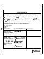
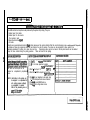
COMDIAL
DIGITECH
Digital Telephone System
System Manual
This publiiion is @icable to the
following COmmoR #IQ@mmt:
- CQ408 Rev. A and l8ter
( -‘.CX!6$6 Rev. A and kter
’ 4$&Z@ Rev. A and later
PKOlO-004
12
MI 66-083.01
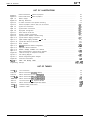
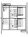
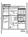
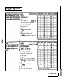
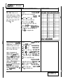
Table Of Contents
TABLE OF CONTENTS
CHAPTER 1 SYSTEM OVERVIEW
. . . . . . . . . . . . . . . . . . . . . . . . . . . . .
1-l
SECTION 1 INTRODUCTION . . . . . . . . . . . . . . . . . . . . . . . . . . . . . . . . . . . . . . . . . l - l
SECTION 2 PUBLICATIONS OVERVIEW . . . . . . . . . . . . . . . . . . . . . . . . . . . . . . . . . . 1-2
..l- 2
ManualScope
. . . . . . . . . . . . . . . . . . . . . . . . . . . . . . . . . . . . . . . . . . . . . . . . . . . .
l-2
Related Publications . . . . . . . . . . . . . . . . . . . . . . . . . . . . . . . . . . . . . . . . . . . . . . . . . . .
SECTION 3 HARDWARE SUMMARY . . . . . . . . . . . . . . . . . . . . . . . . . . . . . . . . . . . . 1-3
l-3
Common Equipment Description . . . . . . . . . . . . . . . . . . . . . . . . . . . . . . . . . . . . . . . . . . . .
l-3
Station Description . . . . . . . . . . . . . . . . . . . . . . . . . . . . . . . . . . . . . . . . . . . . . . . . . . . .
SECTION 4 GENERAL SPECIFICATIONS . . . . . . . . . . . . . . . . . . . . . . . . . . . . . . . . . . 1-8
CHAPTER 2 DESCRIPTION OF SYSTEM FEATURES
. . . . . . . . . . . . . . . . . . 2-I
Abandoned Hold Release . . . . . . . . . . . . . . . . . . . . . . . . . . . . . . . . . . . . . . . . . . . . . . . .
Access Denied . . . . . . . . . . . . . . . . . . . . . . . . . . . . . . . . . . . . . . . . . . . . . . . . . . . . . .
Account Code Button . . . . . . . . . . . . . . . . . . . . . . . . . . . . . . . . . . . . . . . . . . . . . . . . . .
Account Codes Positive Verification . . . . . . . . . . . . . . . . . . . . . . . . . . . . . . . . . . . . . . . . . . .
AtI-Call Paging . . . . . . . . . . . . . . . . . . . . . . . . . . . . . . . . . . . . . . . . . . . . . . . . . . . . . .
Area Paging Interface . . . . . . . . . . . . . . . . . . . . . . . . . . . . . . . . . . . . . . . . . . . . . . . . . .
AssistButton.. . . . . . . . . . . . . . . . . . . . . . . . . . . . . . . . . . . . . . . . . . . . . . . . . . . .
Automatic Call-Back . . . . . . . . . . . . . . . . . . . . . . . . . . . . . . . . . . . . . . . . . . . . . . . . . . .
~~~~t-rdc Dialing . . . . . . . . . . . . . . . . . . . . . . . . . . . . . . . . . . . . . . . . . . . . . . . . . . . .
Automatic Hold For Intercom . . . . . . . . . . . . . . . . . . . . . . . . . . . . . . . . . . . . . . . . . . . . . .
Automatic Hold -Transfer To Intercom . . . . . . . . . . . . . . . . . . . . . . . . . . . . . . . . . . . . . . . . .
Automatic Hold - Transfer To Line . . . . . . . . . . . . . . . . . . . . . . . . . . . . . . . . . . . . . . . . . . . .
Automatic Pause Insertion . . . . . . . . . . . . . . . . . . . . . . . . . . . . . . . . . . . . . . . . . . . . . . . .
Automatic Prbcy ....................................................
Automatic Redial . . . . . . . . . . . . . . . . . . . . . . . . . . . . . . . . . . . . . . . . . . . . . . . . . . . . .
Automatic Station Relocation . . . . . . . . . . . . . . . . . . . . . . . . . . . . . . . . . . . . . . . . . . . . . .
Auxiliary Equipment interface . . . . . . . . . . . . . . . . . . . . . . . . . . . . . . . . . . . . . . . . . . . . . .
Auxiliary Ringer Interface . . . . . . . . . . . . . . . . . . . . . . . . . . . . . . . . . . . . . . . . . . . . . . . .
Background Music . . . . . . . . . . . . . . . . . . . . . . . . . . . . . . . . . . . . . . . . . . . . . . . . . . . .
Basic Key Service (lA2) Emulation . . . . . . . . . . . . . . . . . . . . . . . . . . . . . . . . . . . . . . . . . . .
Battery Back-Up . . . . . . . . . . . . . . . . . . . . . . . . . . . . . . . . . . . . . . . . . . . . . . . . . . . . . .
Battery Back-Up Interface . . . . . . . . . . . . . . . . . . . . . . . . . . . . . . . . . . . . . . . . . . . . . . . .
Block Programming . . . . . . . . . . . . . . . . . . . . . . . . . . . . . . . . . . . . . . . . . . . . . . . . . . .
Call Announce Wiih Handsfree Answerback . . . . . . . . . . . . . . . . . . . . . . . . . . . . . . . . . . . . . .
Call Costing And SMDA Reports . . . . . . . . . . . . . . . . . . . . . . . . . . . . . . . . . . . . . . . . . . . .
Call Forwarding On All Calls . . . . . . . . . . . . . . . . . . . . . . . . . . . . . . . . . . . . . . . . . . . . . . .
Call Forwarding - Personal . . . . . . . . . . . . . . . . . . . . . . . . . . . . . . . . . . . . . . . . . . . . . . .
CallPark . . . . . . . . . . . . . . . . . . . . . . . . . . . . . . . . . . . . . . . . . . . . . . . . . . . . . . .
Call Pickup - Directed . . . . . . . . . . . . . . . . . . . . . . . . . . . . . . . . . . . . . . . . . . . . . . . . . .
Call Pickup - Group . . . . . . . . . . . . . . . . . . . . . . . . . . . . . . . . . . . . . . . . . . . . . . . . . . .
Call Transfer - Screened . . . . . . . . . . . . . . . . . . . . . . . . . . . . . . . . . . . . . . . . . . . . . . . . .
Call Transfer - Unscreened . . . . . . . . . . . . . . . . . . . . . . . . . . . . . . . . . . . . . . . . . . . . . . .
CalI Waiting Tone
. . . . . . . . . . . . . . . . . . . . . . . . . . . . . . . . . . . . . . . . . . . . . . . . . . . .
Calling Station Identification On BLF . . . . . . . . . . . . . . . . . . . . . . . . . . . . . . . . . . . . . . . . . .
Class Of Service Programming (From Main Station) . . . . . . . . . . . . . . . . . . . . . . . . . . . . . . . . . . .
Class Of Service Programming (From VDT) . . . . . . . . . . . . . . . . . . . . . . . . . . . . . . . . . . . . . .
Class of Service Program Printout . . . . . . . . . . . . . . . . . . . . . . . . . . . . . . . . . . . . . . . . . . .
Common Audible Ringer Interface . . . . . . . . . . . . . . . . . . . . . . . . . . . . . . . . . . . . . . . . . . . .
&nferencing - Add-On
.................................................
2-l
2-l
2-l
2-1
2-1
2-1
..2- 1
2-1
2-2
2-2
2-2
2-2
2-2
2-2
2-2
2-2
2-2
2-2
2-3
2-3
2-3
2-3
2-3
2-3
2-3
2-4
2-4
. . 2 -4
2-4
2-4
2-4
2-5
2-5
2-5
2-5
2-5
2-5
2-5
2-6
IMI 66-r-
Table Of Contents
2-6
Conferencing - Multiline . . . . . . . . . . . . . . . . . . . . . . . . . . . . . . . . . . . . . . . . . . . . . . . . .
.
.
.
.
.
.
.
.
.
.
.
.
.
.
.
.
.
.
.
.
.
.
.
.
.
.
.
.
.
.
.
.
.
.
.
.
.
.
.
.
.
.
.
.
.
.
2-6
Conferencing - Unsupervised
..26
DataSecurity
. . . . . . . . . . . . . . . . . . . . . . . . . . . . . . . . . . . . . . . . . . . . . . . . . . . .
.
.
.
.
.
.
.
.
.
.
.
.
.
.
.
.
.
.
.
.
.
.
.
.
.
.
.
.
.
.
.
.
.
.
.
.
.
.
.
.
.
.
.
.
.
.
.
2-6
Default Functional Program
2-6
Defautt Toll Restriction . . . . . . . . . . . . . . . . . . . . . . . . . . . . . . . . . . . . . . . . . . . . . . . . . .
2-6
Delayed Ringing . . . . . . . . . . . . . . . . . . . . . . . . . . . . . . . . . . . . . . . . . . . . . . . . . . . . .
2-6
Departmental Calling Distribution Report . . . . . . . . . . . . . . . . . . . . . . . . . . . . . . . . . . . . . . . .
2-7
.
.
.
.
.
.
.
.
.
.
.
.
.
.
.
.
.
.
.
.
.
.
.
.
.
.
.
.
.
.
.
.
.
.
.
.
.
.
.
.
.
.
.
Designated Programmable Buttons
.
.
.
.
.
.
.
.
.
.
.
.
.
.
.
.
.
.
.
.
.
.
.
.
.
.
.
.
.
.
.
.
.
.
.
.
.
.
.
.
.
.
.
.
.
.
.
2-7
Dial 0 For System Attendant
2-7
.
.
.
.
.
.
.
.
.
.
.
.
.
.
.
.
.
.
.
.
.
.
.
.
.
.
.
.
.
.
.
.
.
.
.
.
.
.
.
.
.
.
.
Direct Department Calling With DCD
2-8
Direct Inward Station Dialing . . . . . . . . . . . . . . . . . . . . . . . . . . . . . . . . . . . . . . . . . . . . . .
2-9
Direct Station Call Hold . . . . . . . . . . . . . . . . . . . . . . . . . . . . . . . . . . . . . . . . . . . . . . . . .
2-9
Direct Station Selection Programmable . . . . . . . . . . . . . . . . . . . . . . . . . . . . . . . . . . . . . . . . .
2-9
Distinctive Ringing . . . . . . . . . . . . . . . . . . . . . . . . . . . . . . . . . . . . . . . . . . . . . . . . . . . .
2-9
Do Not Disturb . . . . . . . . . . . . . . . . . . . . . . . . . . . . . . . . . . . . . . . . . . . . . . . . . . . . . .
2-9
.
.
.
.
.
.
.
.
.
.
.
.
.
.
.
.
.
.
.
.
.
.
.
.
.
.
.
.
.
.
.
.
.
.
.
.
.
.
.
.
.
.
.
.
.
.
.
.
.
.
Do Not Disturb Inhibit
.
.
.
.
.
.
.
.
.
.
.
.
.
.
.
.
.
.
.
.
.
.
.
.
.
.
.
.
.
.
.
.
.
.
.
.
.
.
.
.
.
.
.
.
.
.
.
.
.
2-9
Do Not Disturb Override
.
.
.
.
.
.
.
.
.
.
.
.
.
.
.
.
.
.
.
.
.
.
.
.
.
.
.
.
.
.
.
.
.
.
.
.
.
.
.
.
.
.
.
.
.
.
.
.
.
.
.
.
.
.
2-g
Dual Intercom
2-9
Dynamic Line Buttons . . . . . . . . . . . . . . . . . . . . . . . . . . . . . . . . . . . . . . . . . . . . . . . . . .
.2-l 0
End-To-End Signalling On Intercom . . . . . . . . . . . . . . . . . . . . . . . . . . . . . . . . . . . . . . . . . .
2-9
End-To-End Signailing On Lines . . . . . . . . . . . . . . . . . . . . . . . . . . . . . . . . . . . . . . . . . . . .
2-9
Exclusive Hold . . . . . . . . . . . . . . . . . . . . . . . . . . . . . . . . . . . . . . . . . . . . . . . . . . . . . .
.2-l
0
.
.
.
.
.
.
.
.
.
.
.
.
.
.
.
.
.
.
.
.
.
.
.
.
.
.
.
.
.
.
.
.
.
.
.
.
.
Exclusive Hold System-Wide Enable/Disable
.2-l
o
.
.
.
.
.
.
.
.
.
.
.
.
.
.
.
.
.
.
.
.
.
.
.
.
.
.
.
.
.
.
.
.
.
.
.
.
.
.
.
.
.
.
.
.
.
Executive/Attendant Override
.2-1 o
External Paging Interface . . . . . . . . . . . . . . . . . . . . . . . . . . . . . . . . . . . . . . . . . . . . . . .
.2-10
Feature Inhibit . . . . . . . . . . . . . . . . . . . . . . . . . . . . . . . . . . . . . . . . . . . . . . . . . . . . .
.2-l o
Flexible Ringing Assignments . . . . . . . . . . . . . . . . . . . . . . . . . . . . . . . . . . . . . . . . . . . . .
.2-l o
Flexible Ringing Assignments Of PA Port . . . . . . . . . . . . . . . . . . . . . . . . . . . . . . . . . . . . . . .
.2-l 1
Flexible Station And Line Class Of Service Control . . . . . . . . . . . . . . . . . . . . . . . . . . . . . . . . . .
.2-l o
Flexible Station Numbering Plan . . . . . . . . . . . . . . . . . . . . . . . . . . . . . . . . . . . . . . . . . . .
.
.
.
.
.
.
.
.
.
.
.
.
.
.
.
.
.
.
.
.
.
.
.
.
.
.
.
.
.
.
.
.
.
.
.
.
.
.
.
.2-f o
Full Button Programmability Of Features
.2-l 1
.
.
.
.
.
.
.
.
.
.
.
.
.
.
.
.
.
.
.
.
.
.
.
.
.
.
.
.
.
.
.
.
.
.
.
.
.
.
.
.
.
.
.
.
.
.
.
Handsfree Answer Inhibit
.2-11
.
.
.
.
.
.
.
.
.
.
.
.
.
.
.
.
.
.
.
.
.
.
.
.
.
.
.
.
.
.
.
.
.
.
.
.
.
.
.
.
.
.
.
.
.
.
IHoldAndIUselndications
.2-11
Idle Line Preference . . . . . . . . . . . . . . . . . . . . . . . . . . . . . . . . . . . . . . . . . . . . . . . . . .
.2-l 1
intercom Call Progress Tones . . . . . . . . . . . . . . . . . . . . . . . . . . . . . . . . . . . . . . . . . . . . .
.2-11
IntercomHuntGroup . . . . . . . . . . . . . . . . . . . . . . . . . . . . . . . . . . . . . . . . . . . . . . . . . .
.2-l 1
Intercom Line Timeout . . . . . . . . . . . . . . . . . . . . . . . . . . . . . . . . . . . . . . . . . . . . . . . . .
.2-l 1
Last Number Redial . . . . . . . . . . . . . . . . . . . . . . . . . . . . . . . . . . . . . . . . . . . . . . . . . .
.2-12
LCD Messaging . . . . . . . . . . . . . . . . . . . . . . . . . . . . . . . . . . . . . . . . . . . . . . . . . . . .
LCDSupport.......................................................2-1
2
.2-12
Line Access Restriction . . . . . . . . . . . . . . . . . . . . . . . . . . . . . . . . . . . . . . . . . . . . . . . .
.2-12
Line Answer From Any Station (Night Mode) . . . . . . . . . . . . . . . . . . . . . . . . . . . . . . . . . . . . .
.2-12
Line Groups . . . . . . . . . . . . . . . . . . . . . . . . . . . . . . . . . . . . . . . . . . . . . . . . . . . . . .
.2-12
Line Preselection . . . . . . . . . . . . . . . . . . . . . . . . . . . . . . . . . . . . . . . . . . . . . . . . . . .
.2-12
Line And Line Group Queuing . . . . . . . . . . . . . . . . . . . . . . . . . . . . . . . . . . . . . . . . . . . . .
.2-12
Manual Hold . . . . . . . . . . . . . . . . . . . . . . . . . . . . . . . . . . . . . . . . . . . . . . . . . . . . . .
Meet-Me Answer Page . . . . . . . . . . . . . . . . . . . . . . . . . . . . . . . . . . . . . . . . . . . . . . . .
.2-l 2
. . . . . . . . . . . . . . . . . . . . . . . . . . . . . . . . . . . . . . . . .
.2-l 2
Memory Retention Without Batteries
.
.
.
.
.
.
.
.
.
.
.
.
.
.
.
.
.
.
.
.
.
.
.
.
.
.
.
.
.
.
.
.
.
.
.
.
.
.
.
.
.
.
.
.
.
.
.
.
.
.
.
.2-12
Message Waiting
.2-13
Modular Wring And Jacks . . . . . . . . . . . . . . . . . . . . . . . . . . . . . . . . . . . . . . . . . . . . . . .
.2-13
Music Interface . . . . . . . . . . . . . . . . . . . . . . . . . . . . . . . . . . . . . . . . . . . . . . . . . . . . .
Music-ChpHoltj . . . . . . . . . . . . . . . . . . . . . . . . . . . . . . .
.F. . . . . . . . . . . . . . . . . . . . .
.2-13
.2-13
Music-On-Hold System-Wide Enable/Disable . . . . . . . . . . . . . . . . . . . . . . . . . . . . . . . . . . . . .
Ml& . . . . . . . . . . . . . . . . . . . . . . . . . . . . . . . . . . . . . . . . . . . . . . . . . . . . . . . . .
..2-13
.2-13
Night Transfer (Of Ringing) . . . . . . . . . . . . . . . . . . . . . . . . . . . . . . . . . . . . . . . . . . . . . .
.
.
.
.
.
.
.
.
.
.
.
.
.
.
.
.
.
.
.
.
.
.
.
.
.
.
.
.
.
.
.
.
.
.
.
.
.
.
.
.
.
.
.
.
.
.
.
.
.
.
.
.
On-Hook Dialing
.2-13
Iv
.lJll otPutr3
Table Of Contents
Originating Denied . . . . . . . . . . . . . . . . . . . . . . . . . . . . . . . . . . . . . . . . . . . . . . . . . . .
PBXICENTREXICO Compatible . . . . . . . . . . . . . . . . . . . . . . . . . . . . . . . . . . . . . . . . . . . .
Personalized Ringing Tone . . . . . . . . . . . . . . . . . . . . . . . . . . . . . . . . . . . . . . . . . . . . . .
Pooled Line Access . . . . . . . . . . . . . . . . . . . . . . . . . . . . . . . . . . . . . . . . . . . . . . . . . .
Power Failure Transfer . . . . . . . . . . . . . . . . . . . . . . . . . . . . . . . . . . . . . . . . . . . . . . . .
Prime Line Automatic . . . . . . . . . . . . . . . . . . . . . . . . . . . . . . . . . . . . . . . . . . . . . . . . .
Privacy - Designated Programmable Button . . . . . . . . . . . . . . . . . . . . . . . . . . . . . . . . . . . . .
Privacy Release/Brokerage Service . . . . . . . . . . . . . . . . . . . . . . . . . . . . . . . . . . . . . . . . . .
Private Lines (Access Denied) . . . . . . . . . . . . . . . . . . . . . . . . . . . . . . . . . . . . . . . . . . . . .
Programmable Direct Station Selection/Busy Light Field . . . . . . . . . . . . . . . . . . . . . . . . . . . . . . .
Programmable Buttons . . . . . . . . . . . . . . . . . . . . . . . . . . . . . . . . . . . . . . . . . . . . . . . .
Pulse/Tone Switchable . . . . . . . . . . . . . . . . . . . . . . . . . . . . . . . . . . . . . . . . . . . . . . . .
Response Messaging . . . . . . . . . . . . . . . . . . . . . . . . . . . . . . . . . . . . . . . . . . . . . . . . .
. . . . . . . . . . . . . . . . . . . . . . . . . . . . . . . . . . . . . .
Remote Programming And Administration
Ringing Line Preference . . . . . . . . . . . . . . . . . . . . . . . . . . . . . . . . . . . . . . . . . . . . . . . .
Saved Number Rediat . . . . . . . . . . . . . . . . . . . . . . . . . . . . . . . . . . . . . . . . . . . . . . . . .
secure Off-Hook Voice Announce . . . . . . . . . . . . . . . . . . . . . . . . . . . . . . . . . . . . . . . . . . .
secure Off-Hook Voice Announce Button . . . . . . . . . . . . . . . . . . . . . . . . . . . . . . . . . . . . . . .
Secure Off-Hook Voice Announce Groups . . . . . . . . . . . . . . . . . . . . . . . . . . . . . . . . . . . . . .
Self Diagnostics . . . . . . . . . . . . . . . . . . . . . . . . . . . . . . . . . . . . . . . . . . . . . . . . . . . .
Service Observing . . . . . . . . . . . . . . . . . . . . . . . . . . . . . . . . . . . . . . . . . . . . . . . . . . .
Speakerphone Support . . . . . . . . . . . . . . . . . . . . . . . . . . . . . . . . . . . . . . . . . . . . . . . .
. . . . . . . . . . . . . . . . . . . . . . . . . . . . . . . . . . . . . . . . . .
SquareNon-Square Configuration
.
.
.
.
.
.
. . . . . . . . . . . . . . . . . . . . . . . . . . . . . . . . . . . . . . . . .
Station By Station Privacy
.
. . . . . . . . . . . . . . . . . . . . . . . . . . . . . . . . . . . . . . . . .
Station Message Detail Accounting
.
. . . . . . . . . . . . . . . . . . . . . . . . . . . . . . . . . . . . . . . . .
Station Message Detail Recording
Station Monitoring With DSS Call Pickup . . . . . . . . . . . . . . . . . . . . . . . . . . . . . . . . . . . . . . .
Station Speed Dial . . . . . . . . . . . . . . . . . . . . . . . . . . . . . . . . . . . . . . . . . . . . . . . . . . .
Station-To-Station Messaging . . . . . . . . . . . . . . . . . . . . . . . . . . . . . . . . . . . . . . . . . . . . .
. . . . . . . . . . . . . . . . . . . . . . . . . . . . . . . . . . . . . . . . . . . . . . . . . . .
Subdued Ringing
System Alarm Reports . . . . . . . . . . . . . . . . . . . . . . . . . . . . . . . . . . . . . . . . . . . . . . . . .
System Speed Dial . . . . . . . . . . . . . . . . . . . . . . . . . . . . . . . . . . . . . . . . . . . . . . . . . .
Tandem Attendant . . . . . . . . . . . . . . . . . . . . . . . . . . . . . . . . . . . . . . . . . . . . . . . . . . .
Tap (Flash)lRecafl . . . . . . . . . . . . . . . . . . . . . . . . . . . . . . . . . . . . . . . . . . . . . . . . . . . .
Tenant Service . . . . . . . . . . . . . . . . . . . . . . . . . . . . . . . . . . . . . . . . . . . . . . . . . . . . .
Timed Hold Recall . . . . . . . . . . . . . . . . . . . . . . . . . . . . . . . . . . . . . . . . . . . . . . . . . . . .
. . . . . . . . . . . . . . . . . . . . . . . . . . . . . . . . . . . . . . . . . . . . . . .
Toll Restriction (0 And 1)
. . . . . . . . . . . . . . . . . . . . . . . . . . . . . . . . . . . . . . . . . . . . . . .
Toll Restriiion (Flexible)
. . . . . . . . . . . . . . . . . . . . . . . . . . . . . . . . . . . . . . . . . . . . .
Toll Restriction (Night Mode)
Tone Or Voice Signalling (Intercom) . . . . . . . . . . . . . . . . . . . . . . . . . . . . . . . . . . . . . . . . . .
Transfer/Conference Button . . . . . . . . . . . . . . . . . . . . . . . . . . . . . . . . . . . . . . . . . . . . . .
Unanswered Call Transfer Recall Timing . . . . . . . . . . . . . . . . . . . . . . . . . . . . . . . . . . . . . . .
Voice Announce Blocking . . . . . . . . . . . . . . . . . . . . . . . . . . . . . . . . . . . . . . . . . . . . . . .
Voice Mail Transfer on Busy . . . . . . . . . . . . . . . . . . . . . . . . . . . . . . . . . . . . . . . . . . . . . .
. . . . . . . . . . . . . . . . . . . . . . . . . . . . . . . . . . . . . . . . .
Zone Paging (Via Station Speakers)
CHAPTER 3 INSTALLATION . . . . . . . . . . . . . . . . . . . . . . . . . . . . . . . .
.2-l 3
.2-13
.2-l 3
.2-13
.2-l 3
.2-13
.2-l 4
.2-14
.2-14
2-14
.2-14
.2-14
.2-14
.2-14
.2-14
.2-l 4
.2-14
.2-l 5
.2-15
.2-16
.2-16
.2-16
.2-16
.2-l 6
.2-l 6
.2-16
.2-16
.2-16
2-l 6
.2-17
.2-17
.2-17
.2-17
.2-37
.2-17
.2-17
.2-17
.2-l 7
.2-17
.2-l 8
.2-l 8
.2-l 8
.2-18
.2-l 8
.2-l 8
3-l
i STANDARD INSTALLATION DETAILS . . . . . . . . . . . . . . . . . . . . . . . . . . . . . 3.1
. . . . . . . . . . . . . . . . . . . . . . . . . . . . . . . . . . . . . . . . . . . . . . . .
3-l
Mounting Considerations
. . . . . . . . . . . . . . . . . . . . . . . . . . . . . . . . . . . . . . . . . . . . . . . . . . .
3-l
Mounting Procedure
.
.
.
.
.
.
.
.
.
.
.
.
.
.
.
.
.
.
.
.
.
.
3-3
:
AC Power Connection . . . . . . . . . . . . . . . . . . . . . . . . . . .
. . . . . . . . . . . . . . . . . . . . . . . . . . . . . . . . . . . . . . . . . . . . . . . . . . . .
3-3
System Grounding
. . . . . . . . . . . . . . . . . . . . . . . . . . . . . . . . . . . . . . . . . . . . . . . . . . . .
3-5
Line Connections
. . . . . . . . . . . . . . . . . . . . . . . . . . . . . . . . . . . . . . . . . . . . . . . . . . .
3-5
Station Connections
SECTION
V
IMI 66,’
Table Of Contents
SECTION 2 OPTION INSTALLATION DETAILS . . . , . . . , . . . . . . . . . . . . . . . . . . . . . .
3-14
Key System/Hybrid Configuration . . . . . . . . . . . . . . . . . . . . . . . . . . . . . . . . . . . . . . . . . . .
Power Failure Station Connections . . . . . . . . . . . . . . . . . . . . . . . . . . . . . . . . . . . . . . . . . .
Auxiliary Equipment Interface . . . . . . . . . . . . . . . . . . . . . . . . . . . . . . . . . . . . . . . . . . . . .
Common Audible And Auxiliary Ringing interface . . . . . . . . . . . . . . . . . . . . . . . . . . . . . . . . . . .
External Paging Interface . . . . . . . . . . . . . . . . . . . . . . . . . . . . . . . . . . . . . . . . . . . . . . .
External Paging Interface - Line Port . . . . . . . . . . . . . . . . . . . . . . . . . . . . . . . . . . . . . . . . .
Data Device Connections . . . . . . . . . . . . . . . . . . . . . . . . . . . . . . . . . . . . . . . . . . . . . . .
Music Interface . . . . . . . . . . . . . . . . . . . . . . . . . . . . . . . . . . . . . . . . . . . . . . . . . . . . .
.3-l 4
.3-l 5
.3-l 6
.3-l 7
.3-l 8
.3-l 9
.3-20
.3-22
. . . . . . . . . . . . . . . . . . . . . . . . . . . . . .
SECTION 3 ADD-ON EXPANSION MODULES
.
.
.
.
.
.
.
.
.
.
.
.
.
.
.
.
.
.
.
.
.
.
.
. . . . . . . . . . . . . . . . . . . . . . . . . . . . . . .
Introduction
.
.
.
.
.
.
.
.
.
.
.
.
.
.
.
.
.
.
.
.
.
.
.
.
. . . . . . . . . . . . . . . . . . . . . . . . . . . . . . .
Installation
.3-23
.3-26
SECTION 4 SOFTWARE CARTRIDGE , . . . . . . . . . . . . . . . . . . . . . . . . . . . . . . . . . .
3-27
. . . . . . . . . . . . . . . . . . . . . . . . . . . . . . . . . . . . . . . . . . . . . . . . . . . . . .
Introduction
Installation . . . . . . . . . . . . . . . . . . . . . . . . . . . . . . . . . . . . . . . . . . . . . . . . . . . . . . .
3.23
.3-27
.3-27
SECTION 5 DATA COMMUNICATIONS WITH THE DIGITALTELEPHONE SYSTEM . . . . . . . . . . 3-29
.3-29
Equipment Required . . . . . . . . . . . . . . . . . . . . . . . . . . . . . . . . . . . . . . . . . . . . . . . . . .
.3-29
Connections . . . . . . . . . . . . . . . . . . . . . . . . . . . . . . . . . . . . . . . . . . . . . . . . . . . . . .
.3-29
Communications Procedures . . . . . . . . . . . . . . . . . . . . . . . . . . . . . . . . . . . . . . . . . . . . .
3-31
SECTION 6 SYSTEM CHECKOUT AND FAILURE ISoLATloN . . . . . . . . . . , . . . . . . . . . . .
.3-31
Initial Condition . . . . . . . . . . . . . . . . . . . . . . . . . . . . . . . . . . . . . . . . . . . . . . . . . . . .
..3-3 1
Checkout . . . . . . . . . . . . . . . . . . . . . . . . . . . . . . . . . . . . . . . . . . . . . . . . . . . . . .
.
.
.
.
.
.
.
.
.
.
.
.
.
.
.
.
.
.
.
.
.
.
.
.
.
.
.
.
.
.
.
.
.
.
.
.
.
.
.
.
.
.
.
.
.
.
.
.
.
.
.
.3-31
Resistance Check
, ..............................
.3-31
VoWe Check . . . . . . . . . . . . . . . . . . . . . .
.3-31
General Check . . . . . . . . . . . . . . . . . . . . . . . . . . . . . . . . . . . . . . . . . . . . . . . . . . . . .
.3.31
Failure Isolation . . . . . . . . . . . . . . . . . . . . . . . . . . . . . . . . . . . . . . . . . . . . . . . . . . . .
SECTION 7 FCC RULES AND REGULATIONS
. . . . . . . . . . . . . .
, . . . . . . . . . . . . . . . 3.32
CHAPTER 4 SYSTEM PROGRAMMING . . . . . . . . . , . . . . . . . . . . . . . . . . 4-1
SECTION i GENERAL INFORMATION . . . . . . . . . . . . . . . . . . . . . . . . . . . . . . . . . . . 4-j
Programming Overlays
. . . . . . . . . . . . . . . . . . . . . . . . . . . . . . . . . . . . . . . . . . . . . . . . .
4-1
SECTION 2 CLASS OF SERVICE PROGRAMMING . . . . . . . . . . . . . . . . . . . . . . . . . . . . . 4.2
Master Clear . . . . . . . . . . . . . . . . . . . . . . . . . . . . . . . . . . . . . . . . . . . . . . . . . . . . . . .
System Defautts . . . . . . . . . . . . . . . . . . . . . . . . . . . . . . . . . . . . . . . . . . . . . . . . . . . . .
System Configuration . . . . . . . . . . . . . . . . . . . . . . . . . . . . . . . . . . . . . . . . . . . . . . . . . .
Line Configuration . . . . . . . . . . . . . . . . . . . . . . . . . . . . . . . . . . . . . . . . . . . . . . . . . . .
Station Configuration . . . . . . . . . . . . . . . . . . . . . . . . . . . . . . . . . . . . . . . . . . . . . . . . .
Direct Inward Station Dialing . . . . . . . . . . . . . . . . . . . . . . . . . . . . . . . . . . . . . . . . . . . . .
Analog Terminal Interface . . . . . . . . . . . . . . . . . . . . . . . . . . . . . . . . . . . . . . . . . . . . . . .
Toll Restriction Table Configuration . . . . . . . . . . . . . . . . . . . . . . . . . . . . . . . . . . . . . . . . . .
Data Printer Service . . . . . . . . . . . . . . . . . . . . . . . . . . . . . . . . . . . . . . . . . . . . . . . . . .
Integrated Call Costing . . . . . . . . . . . . . . . . . . . . . . . . . . . . . . . . . . . . . . . . . . . . . . . .
Station Message Detail Accounting Reporting . . . . . . . . . . . . . . . . . . . . . . . . . . . . . . . . . . . .
. . . . . . . . . . . . . . . . . . . . . . . . . . . . . . . . . . . . . . . . . . . . . . . .
Attendant Configuration
SECTION 3 VIDEO DISPLAY TERMINAL PROGRAMMING
. . . . . . . . . . . . . . . . . . . . . . . 4-83
lntdu&n . . . . . . . . . . . . . . . . . .
: . . . . . . . . . . . . . . . . . . . . . . . . . . . . . . . . . . .
VDT Programming Procedure . . . . . . . . . . . . . . . . . . . . . . .
., . . . . . . . . . . . . . . . . . . . . .
.
.
.
.
.
.
.
.
.
.
.
.
.
.
.
.
.
.
.
.
.
.
.
.
.
.
.
.
.
.
. . . . . . . . . . . . . . . . . . .
Remote Programming
.
.
.
.
.
.
.
.
.
.
.
.
.
.
.
.
.
.
.
.
.
.
.
.
.
.
.
.
.
.
. . . . . . . . . . . . . . . . . . .
Typical PC Operation
.
.
.
.
.
.
.
.
.
.
.
.
.
.
.
.
.
.
.
.
.
.
.
.
.
.
.
.
.
.
.
.
.
. . . . . . . . . . . . . . . . . .
Menu Descriptions
.
.
.
.
.
.
.
.
.
.
.
.
.
.
.
.
.
.
.
.
.
.
.
.
.
.
.
.
.
.
.
. . . . . . . . . . . . . . . . . .
Main Menu Selections
vi
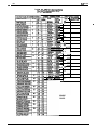
4-3
4.4
4-5
.4-14
.4-22
.4-53
.4-55
.4-58
.4-64
.4-65
.4-74
.4-78
.4-83
.4-83
.4-84
.4-84
.4-87
.4-87
Table Of Contents
. . . . . . . . . . . . . . . . . . . . . . . . . . . . . . . . . . . . . . . . . . . .
System COS Menu Selections
. . . . . . . . . . . . . . . . . . . . . . . . . . . . . . . . . . . . . . . . . . . . . .
Line COS Menu Selections
Station COS Menu Selections . . . . . . . . . . . . . . . . . . . . . . . . . . . . . . . . . . . . . . . . . . . . .
. . . . . . . . . . . . . . . . . . . . . . . . . . . . . . . . . . . . . . . . .
Toll Restriction Table Administration
.4-87
.4-88
.4-89
.4-90
CHAPTER 5 SYSTEM OPERATING PROCEDURES . . . . . . . . . . . . . . . . . . . . 5-l
SECTION 1 STATION OPERATION
. . . . . . . . . . . . . . . . . . . . . . . . . . . . . . . . . . . . . 5-l
Answering Calls . . . . . . . . . . . . . . . . . . . . . . . . . . . . . . . . . . . . . . . . . . . . . . . . . . . . .
Making Calls . . . . . . . . . . . . . . . . . . . . . . . . . . . . . . . . . . . . . . . . . . . . . . . . . . . . . . .
Holding Calls . . . . . . . . . . . . . . . . . . . . . . . . . . . . . . . . . . . . . . . . . . . . . . . . . . . . . . .
Transferring Calls . . . . . . . . . . . . . . . . . . . . . . . . . . . . . . . . . . . . . . . . . . . . . . . . . . . .
Conferencing . . . . . . . . . . . . . . . . . . . . . . . . . . . . . . . . . . . . . . . . . . . . . . . . . . . . . . .
Messaging . . . . . . . . . . . . . . . . . . . . . . . . . . . . . . . . . . . . . . . . . . . . . . . . . . . . . . . .
Voice Announce Blocking . . . . . . . . . . . . . . . . . . . . . . . . . . . . . . . . . . . . . . . . . . . . . . . .
. . . . . . . . . . . . . . . . . . . . . . . . . . . . . . . . . . . . . . . . . . . . . . . . . . . . .
Line Monitoring
Recall/Flash . . . . . . . . . . . . . . . . . . . . . . . . . . . . . . . . . . . . . . . . . . . . . . . . . . . . . . .
Paging . . . . . . . . . . . . . . . . . . . . . . . . . . . . . . . . . . . . . . . . . . . . . . . . . . . . . . . . . .
Do Not Disturb . . . . . . . . . . . . . . . . . . . . . . . . . . . . . . . . . . . . . . . . . . . . . . . . . . . . . .
MuteIHandsfree
Answer Inhibit
. . . . . . . . . . . . . . . . . . . . . . . . . . . . . . . . . . . . . . . . . . . . .
Pulse/Tone
Switching . . . . . . . . . . . . . . . . . . . . . . . . . . . . . . . . . . . . . . . . . . . . . . . . . .
Personal Ringing Tones . . . . . . . . . . . . . . . . . . . . . . . . . . . . . . . . . . . . . . . . . . . . . . . . .
Background Music . . . . . . . . . . . . . . . . . . . . . . . . . . . . . . . . . . . . . . . . . . . . . . . . . . . .
CaltFonvard . . . . . . . . . . . . . . . . . . . . . . . . . . . . . . . . . . . . . . . . . . . . . . . . . . . . .
Automatic Call-Back . . . . . . . . . . . . . . . . . . . . . . . . . . . . . . . . . . . . . . . . . . . . . . . . . . .
CallWaiting
. . . . . . . . . . . . . . . . . . . . . . . . . . . . . . . . . . . . . . . . . . . . . . . . . . . . .
Service Observing . . . . . . . . . . . . . . . . . . . . . . . . . . . . . . . . . . . . . . . . . . . . . . . . . . .
5-1
5-2
5-4
5-4
5-5
5-5
5-6
5-6
5-6
5-7
5-7
5-8
5-7
5-8
5-8
..5- 9
5-9
. . 5 -9
.5-lo
Executive Override . . . . . . . . . . . . . . . . . . . . . . . . . . . . . . . . . . . . . . . . . . . . . . . . . . .
-5-l 0
Speakerphone
. . . . . . . . . . . . . . . . . . . . . . . . . . . . . . . . . . . . . . . . . . . . . . .
.5-l 1
Departmental Station Operation . . . . . . . . . . . . . . . . . . . . . . . . . . . . . . . . . . . . . . . . . . . .
Station User Programming . . . . . . . . . . . . . . . . . . . . . . . . . . . . . . . . . . . . . . . . . . . . . . .
.5-l I
Operation
SECTION 2 ATTENDANT STATION OPERATION . . . . . . . . . . . . . . . . . . . . . . . . . . . . .
System Clock . . . . . . . . . . . . . . . . . . . . . . . . . . . . . . . . . . . . . . . . . . . . . . . . . . . . .
System Speed Dial Programming . . . . . . . . . . . . . . . . . . . . . . . . . . . . . . . . . . . . . . . . . . .
Night Transfer (Of Ringing)
. . . . . . . . . . . . . . . . . . . . . . . . . . . . . . . . . . . . . . . . . . . . . .
Music On Hold . . . . . . . . . . . . . . . . . . . . . . . . . . . . . . . . . . . . . . . . . . . . . . . . . . . . .
LCD Messaging . . . . . . . . . . . . . . . . . . . . . . . . . . . . . . . . . . . . . . . . . . . . . . . . . . . .
Station Names . . . . . . . . . . . . . . . . . . . . . . . . . . . . . . . . . . . . . . . . . . . . . . . . . . . . .
Station Message Detail Accounting (SMDA) Printout . . . . . . . . . . . . . . . . . . . . . . . . . . . . . . . . .
System Alarm Reporting . . . . . . . . . . . . . . . . . . . . . . . . . . . . . . . . . . . . . . . . . . . . . . . .
Direct Inward Station Dialing
. . . . . . . . . . . . . . . . . . . . . . . . . . . . . . . . . . . . . . . . . . . . .
SECTION 3 SYSTEM OPERATlNG CHARACTERISTICS . . . . . . . . . . . . . . . . . . . . . . . . .
Feature Code Numbering Plan
. . . . . . . . . . . . . . . . . . . . . . . . . . . . . . . . . . . . . . . . . . . .
Ringer Volume Control . . . . . . . . . . . . . . . . . . . . . . . . . . . . . . . . . . . . . . . . . . . . . . . . .
Status Indicators And Tone Sequences . . . . . . . . . . . . . . . . . . . . . . . . . . . . . . . . . . . . . . . .
. . . . . . . . . . . . . . . . . . . . . . . . . . . . . . . . . . . . . . . . . . . . . . . . . . . .
Display Intensity
CHAPTER6 MAINTENANCE . . . . . . . . . . . . . . . . . . . . . . . . . . . .
.5-l 1
5-14
.5-14
.5-14
.5-14
.5-15
.5-15
.5-15
.5-l 7
.5-17
.5-17
5-19
.5-l 9
.5-21
.5-21
-5-21
, . . . 6-I
Technical Assistance And Repair Service . . . . . . . . . . . . . . . . . . . . . . . . . . . . . . . . . . . . . . . .
Fuse Location . . . . . . . . . . . . . . . . . . . . . . . . . . . . . . . . . . . . . . . . . . . . . . . . . . . . . . .
Wiring
. . . . . . . . . . . . . . . . . . . . . . . . . . . . . . . . . . . . . . . . . . . . . . . . . . . . . . . . . .
Station Wall Mounting . . . . . . . . . . . . . . . . . . . . . . . . . . . . . . . . . . . . . . . . . . . . . . . . . .
6-1
6-1
6-1
6-1
IMI 66 ’
Table Of Contents
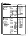
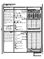
LIST OF ILLUSTRATIONS
. . . . . . . . . . . . . . . . . . . . . . . . . . . . . . .
l-5
Outline Dimensions - Common Equipment
.
.
.
.
.
.
.
.
.
.
.
.
.
.
.
.
.
.
.
.
.
.
.
.
.
.
.
.
.
.
.
.
l-6
Outline Dimensions - Station Equipment
l-7
Station Images . . . . . . . . . . . . . . . . . . . . . . . . . . . . . . . . . . . . . . . . . . . . . .
. . . . . . . . . . . . . . . . . . . . . . . . . . . . . . . . . . . . . . . . . .
3-2
Mounting Dimensions
.
.
.
.
.
.
.
.
.
.
.
.
.
.
.
.
.
.
.
.
.
.
.
.
.
.
.
.
.
3-4
AC Power Connection And System Grounding
. . . . . . . . . . . . . . . . . . . . . . . . .
.3-l 1
Common Equipment, Station And Line Connections
.
.
.
.
.
.
.
.
.
.
.
.
.
.
.
.
.
.
.
.
.
.
.
.
.
.
.
.
.
.
.
.
.
.
.
.
.
.
.
.
.3-l 2
Typical Line Connections
.
.
.
.
.
.
.
.
.
.
.
.
.
.
.
.
.
.
.
.
.
.
.
.
.
.
.
.
.
.
.
.
.
.
.
.
.
.
.3-l 3
Typical Station Connections
.
.
.
.
.
.
.
.
.
.
.
.
.
.
.
.
.
.
.
.
.
.
.
.
.
.
.
.
.
.
.
.
.
.
.
.
.
.
.
.3-l 4
Key/Hybrid Configuration
.
.
.
.
.
.
.
.
.
.
.
.
.
.
.
.
.
.
.
.
.
.
.
.
.
.
.
.
.
.
.
.
.
.
.
.
.
.
.
.3-l 5
Power Failure Connection
. . . . . . . . . . . . . . . . . . . . . . . . . . . . . . . . . . . .
.3-l 6
Auxiliary Interface Connections
3-l 7
Typical Common Audible Interface Wiring . . . . . . . . . . . . . . . . . . . . . . . . . . . . . . .
.
.
.
.
.
.
.
.
.
.
.
.
.
.
.
.
.
.
.
.
.
.
.
.
.
.
.
.
.
.
.
.
.
.
.3-l
8
Typical External Paging Connection
.
.
.
.
.
.
.
.
.
.
.
.
.
.
.
.
.
.
.
.
.
.
.
.
.
.
.
.
3-l
9
Typical External Paging Connection
- Line Port
.3-21
Typical Data Device Connections . . . . . . . . . . . . . . . . . . . . . . . . . . . . . . . . . . .
.
.
.
.
.
.
.
.
.
.
.
.
.
.
.
.
.
.
.
.
.
.
.
.
.
.
.
.
.
.
.
.
.
.
.
.
.
.
.
.
.
.
.
.
.
.3-22
Music Interface
.
.
.
.
.
.
.
.
.
.
.
.
.
.
.
.
.
.
.
.
.
.
.
.
.
.
.
.
.
.
.
.3-24
Add-On Expansion Module Configuration
.
.
.
.
.
.
.
.
.
.
.
.
.
.
.
.
.
.
.
.
.
.
.
.
.
.
.
.
.
.
.
.
.
.
.
.
.
.3-26
Expansion Module Installation
3-28
. . . . . . . . . . . . . . . . . . . . . . . . . . . . .
Software Cartridge Installation and Removal
.3-30
Data Communications Interconnection Diagram . . . . . . . . . . . . . . . . . . . . . . . . . . . .
4-49
Location Of Keys On Telephone Faceplate . . . . . . . . . . . . . . . . . . . . . . . . . . . . . .
.4-67
.
.
.
.
.
.
.
.
.
.
.
.
.
.
.
.
.
.
.
.
.
.
.
.
.
.
.
.
.
.
.
.
.
.
.
.
.
.
.
.
.
.
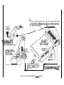
Call Costing Diagram
.4-86
Remote Programming Block Diagram . . . . . . . . . . . . . . . . . . . . . . . . . . . . . . . . .
.
.
.
.
.
.
.
.
.
.
.
.
.
.
.
.
.
.
.
.
.
.
.
.
.
.
.
.
.
.
.
.
.
.
.
.
.
.
.
.
.
.5-l 8
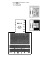
Controls and Indicators
6-2
.
.
.
.
.
.
.
.
.
.
.
.
.
.
.
.
.
.
.
.
.
.
.
.
.
.
.
.
.
.
.
.
.
.
.
.
.
.
Station Wall Mounting Details
.
.
.
.
.
.
.
.
.
.
.
.
.
.
.
.
.
.
.
.
.
.
.
.
.
.
.
.
.
.
.
.
.
.
.
.
.
.
.
.
.
.
.
.
.
.4-91,4-92
Programming Overlays
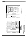
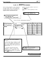
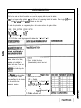
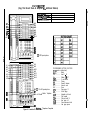
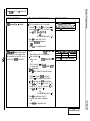
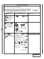
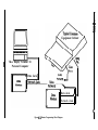
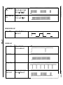
Figure l-1.
Figure l-2.
Figure 1-3.
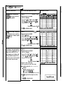
Figure 3-l.
Figure 3-2.
Figure 3-3.
Figure 3-4.
Figure 3-5.
Figure 3-6.
Figure 3-7.
Figure 3-8.
Figure 3-9.
Figure 3-l 0.
Figure 3-l 1.
Figure 3-12.
Figure 3-13.
Figure 3-l 4.
Figure 3-l 5.
Figure 3-l 6.
Figure 3-l 7.
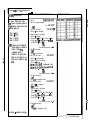
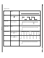
Figure 4-l.
Figure 4-2.
Figure 4-3.
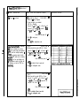
Figure 5-l.
Figure 6-1.
LIST OF TABLES
Table 3-l.
Table 3-2.
Table 3-3.
Table 3-4a.
Table 3.4b.
Table 3-5.
Table 3-6.
Table 4-l.
Table 5-l.
Line Connections . . . . . . . . . . . . . . . . . . . . . . . . . . . . . . . . . . . . . . . . . . . . .
Station Connections (CLine, E-Station) . . . . . . . . . . . . . . . . . . . . . . . . . . . . . . . . .
Station Connections (E-Line, 16Btation) . . . . . . . . . . . . . . . . . . . . . . . . . . . . . . . .
Station Connections (16-Line, 3PStation) . . . . . . . . . . . . . . . . . . . . . . . . . . . . . . . .
Station Connections (16-Line, 32Station) . . . . . . . . . . . . . . . . . . . . . . . . . . . . . . .
Line Connections - 408 Expansion Module . . . . . . . . . . . . . . . . . . . . . . . . . . . . . .
Station Connections - 408 Expansion Module . . . . . . . . . . . . . . . . . . . . . . . . . . . . .
. . . . . . . . . . . . . . . . . . . . . . . . . . . . . . . . . . . .
Character Dialing Codes Chart
.
.
.
.
.
.
.
.
.
. . . . . . . . . . . . . . . . . . . . . . . . . . . . . . . . . . .
Character Codes
3-6
3-7
3-8
3-9
.3-l 0
3-23
.3-25
-4-21
.5-l 6
System Overview
CHAPTER 1
SYSTEM OVERVIEW
SECTION 1
INTRODUCTION
The digital telephone system is an expandable
communications system with many attractive
characteristics including the following:
feature access, line access, messaging and more.
Programmed buttons helps station users eliminate
manual dialing errors.
Unitized base unit which includes all system
features. The base unit is full featured and
self-contained.
Service observing. Supervisors can help insure
quality of service without interrupting calls by
monitoring a trainee’s call without being heard by the
distant party at the trainee’s station.
Expansion modules which increase station and
line capacity. A 4-line, 8-station expansion module is
available. It can be added singly or in pairs to
increase the station and line capacity of an existing
base unit installation.
Secure off-hook voice announce (SOHVA) feature.
The SOHVA feature allows a station user to talk to a
busy station without being heard by the outside party
at the busy station. The called user can easily send
back a pre-programmed LCD message or talk to the
caller without being heard by the outside party.
Programmable buttons. Many of the telephone
buttons can be programmed to provide functions such
as direct station selection (DSS), auto dial, system
Handset volume control on all stations. Handset
volume can be set to a comfortable listening level for
each individual user of the telephone.
Call cost display. Built-in software records all
outside call costs. Special programming allows an
LCD speakerphone to display the accumulating cost of
a call.
Dual intercom. A second intercom key can be
provided so that station users can handle two intercom
calls at once. One intercom call can be placed on
hold while a second intercom call is serviced or both
calls can be conferenced together.
System
IMI 66.
Overview
SECTION 2
PUBLICATIONS OVERVIEW
MANUAL SCOPE
l
This publication contains a technical discussion of the
digital telephone system. Included in this manual is
the following information:
Chapter 1, System Overview: This chapter
provides a generalized understanding of the
system, an explanation of the supporting
documentation, and a summary of the equipment
hardware.
Chapter 2, Feature Description: This chapter
provides a detailed discussion of the features
provided by the digital telephone system.
Chapter 3, Installation: This chapter provides
detailed installation instructions and connection
details.
Chapter 4, Programming: This chapter provides
detailed programming instructions for setting the
operating parameters of the system.
Chapter 5, Operation: This chapter summarizes
operating procedures and provides special tone
and indicator details.
Chapter 6, Maintenance: Special maintenance
details are provided in this chapter.
RELATED
PUBLICATIONS
Related publications, which contain additional
information applicable to this system, are available
from the manufacturer.
They are as follows:
GENERAL INFORMATION
l
IMI 01-005 Handling
Components
of Electrostatically Sensitive
USER INFORMATION
l
GCA 70-l 82 Attendant’s Guide
l
GCA 70-l 83 System User’s Guide
l
GCA 70-l 84 Station User’s Guide
System
. ..a. au-u83
Overview
SECTION 3
HARDWARE SUMMARY
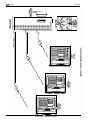
The digital telephone system consists of an electronic
Key Service Unit (KSU) base unit, usually referred to
as common equipment, optional expansion modules to
extend station and line capacities as required, a
software cardridge containing the operating System
programming, dedicated digital electronic key
telephones, and interconnecting wiring consisting of
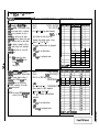
small, 2-- or 4--conductor, twisted-pair cable.
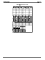
The station and line capacity of the base unit and
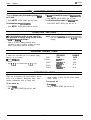
optional expansion module are per the following chart.
MODEL
NO.
CO/PBX
CAPACITY
STATION
CAPACITY
CO408
4
8
CO81 6
8
16
Cl 632
16
32
CM408
4
8
The digital telephone system is full featured, and
supports the digital telephone models.
The digital system is expandable in both line and
station capacity with the addition of add-on expansion
modules. Refer to Figure 3-14 on page 3-24 for an
illustration of the expansion configurations.
COMMON EQUIPMENT DESCRlPTlON
The common equipment base unit is a fully electronic
device. It is essentially a special purpose computer
system acting as a communications controller
between central off ice (CO), private branch exchange
(PBX), or CENTREX supplied lines and the proprietary
digital telephone stations. The software architecture
of the common equipment provides complete system
support and great flexibility of operation.
The system is fully digital and is ISDN up-gradable
with two usable time slots available for each station.
The digital information passes over time division
multiplexing (TDM) highways. The digital information
is an encoded version of the voice transmission and
control signals that are translated into computer
language. The TDM highway can transmit several
signals over a single pair of wires at the same time.
The signals are governed by a system clock. This
clock creates an overall point of reference against
which the TCM information is synchronized and
partitioned into time slots. A time slot is a portion Of
time assigned to a particular position of the system
clock. Each time a particular clock position iS
reached, the information associated with that position
can be read. As the system clock goes through the
clock cycle, all necessary digital information is passed
between the pieces of equipment sharing the highway.
The common equipment consists of a base unit, which
provides complete feature support, and optional
expansion modules which provide extended station
and line coverage.
The wmmon equipment is contained in a functional,
modem-style metal housing of contemporary design in
keeping with the needs of the modem off ice
environment. It is engineered to be wall or rack
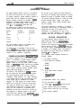
mounted. The outline dimensions of the common
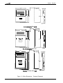
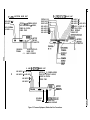
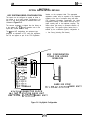
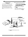
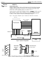
equipment base units are illustrated in Figure l-l.
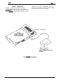
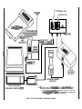
STATION DESCRIPTION
The digital telephone stations employed with the
digital system are electronic, microprocessorcontrolled, devices. They allow not only multiline
pickup but also single key access to features available
from the serving CO, PBX, or CENTREX switch as
well as the wmmon equipment. The digital telephone
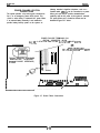
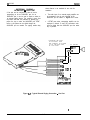
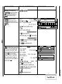
is available in two different images. The features of
the images are as listed below and as detailed in
Figure l-2 and in Figure l-3.
The wide-image digital telephone provides the
following features:
l
l
Full modular connection
3 fixed buttons with indicators
. SPKR
l
.
HOLD
ITCM
3 fixed buttons without indicators
l
TAP
. TRANS/CONF
. MUTE
Programmable buttons with indicators
7-foot, G-conductor line cord
6 position, 4- or 6-conductor
modular line jack
K-type handset (hearing aid compatible)
Ringer volume control (Off, Low, and High)
Wall mounting capability
System
The image designations refer to the number of
programmable buttons located below the keypad,
including the hold and intercom buttons, as opposed
to the number of programmable buttons located above
the keypad.
l
IMI 66
Overview
available in both monitor and speakerphone
versions.
l
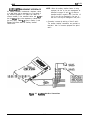
The 10x14 image provides a moderate sized line
button matrix along with a moderate sized priority
line button grouping. This image is best suited for
typical work area stations. The 10x14 image is
l-4
The LCD speakerphone is available in a 5x14
image, This image provides a priority line grouping
and contains a liquid crystal display which shows
call handling data and other usefutinformation.
The
LCD speakerphone is used as an attendant station
as well as being very applicable for use as an
executive station.
System
+I-
&Line, Mtatlon Base Unit
{-
16.50
7- 7 . 4 4
-I+-
Id
,-I
+I--
“.
“:~:x:%:~:::~:z:
:~:~:“:::::::m:x:::~:
gg:““:“:t:.c:“:n:zm:
... . .. . . . . . .
.
x
.
I==/
I
26:35
I
I
26.25
1
Z?
1
I
:
q
0
+-
2.13
&Llne, 16Statlon Base Unit
14.8 7
- 16.50 -
I
!
I
1 i ?6
1
+-I
-=I+,
t- t - 7 . 4 4
+
-I-
0
27
2
2
+
2.89 -c-l
%-Line. 3%Station Base Unit
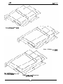
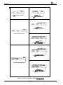
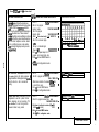
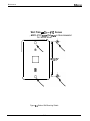
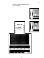
Figure 1-l. Outline Dimensions
l-5
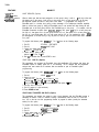
n
Common Equipment
Overview
System Overview
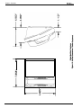
l-6
_- d33
System Overview
J
0
I’r0
0
0
0
0
0
0
t
0
0
0
0
0
l-7
IMI 66-u,.
System Overview
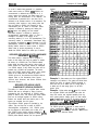
SECTION 4
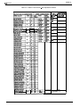
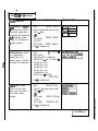
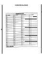
GENERAL SPECIFICATIONS
4-LINE,
8-STATION,
8-LINE,
16-STATION
16-LINE
32STATION
SYSTEM CAPACITY
LINES:
STATIONS:
DSSBLF CONSOLES:
INTERCOM PATHS:
MAXIMUM SIMULTANEOUS
INTERCOM CONVERSATIONS:
PAGING PORTS
PARK ORBITS
SPEED DIALS
SYSTEM
STATION
AUTODIALS
POWER FAIL CIRCUITS
CONFERENCING
(Maximum Combinations
At Any One Time)
4
8
8
16
(FUTURE FEATURE)
Non-blocking
Non-blocking
Non-blocking
Non-blocking
1
9
Non-blocking
1
9
Non-blocking
1
9
99
10
Unused buttons
1
99
10
Unused buttons
1
99
10
Unused buttons
1
16
32
1 five-way plus 1 three-way
plus 2 SOHVA
2 four-way plus 2 SOHVA
1 four-way plus 3 three-way
5 three-way plus 1 SOHVA
4 five-way plus 5 three-way
plus 1 SOHVA
6 four-way plus 2 three-way
3 four-way plus 9 three-way
16 three-way
90 - 129 VAC Singlephase - all models
0.6A
2.0 A
7ow
135w
8OVA
19OVA
2.1A
150w
200VA
16.5
21.3
3.8
17.5
16.5
27.6
4.5
30.5
POWER REQUIREMENTS
(Fully loaded system)
AC POWER:
DIMENSIONS (approximate)
COMMON EQUIPMENT
WIDTH (inches):
HEIGHT(inches):
DEPTH (inches):
WEIGHT (pounds):
16.5
27.1
3.8
26
STATIONS
FOOTPRINT (inches):
WEIGHT (pounds):
8.625 X 7.658
2.5
STATION CABLE REQUIREMENTS
TYPE:
P-wire (l-pair) twisted, non-shielded.
MAXIMUM LENGTH:
1000 feet with 24 gauge wire
SWITCHING PRINCIPLE:
Digital, time division multiplexing (TDM). Provides non-blocking
switching with stored program control
IMI 66-083
dysrem Overview
OPERATlNG
ENVIRONMENT
32-122 degrees F (O-50 degrees C)
TEMPERATURE:
HUMIDIlY:
90 percent relative, non-condensing
TEFlMlNATlONS
Standard 50-pin male connectors for connection to external
distribution field.
Standard, G-conductor mini-jack (USOC 14C)
STATION:
LINE:
STATlON MESSAGE DETAIL
RECORDING PORT
FORMAT:
PARITY:
DATA BITS:
STOP BITS:
BAUD RATE:
HANDSHAKING:
Serial, pseudo RS-232C
None
7 or 8 (programmable)
1 or 2 (programmable)
Programmable in class of service
X o n -Xoff
Hardware - C T S
500 Feet maximum
CABLE LENGTH:
MUSIC INTERFACE
INPUT LEVEL:
INPUT IMPEDANCE:
CONNECTOR:
3 Vofts peak-to-peak maximum
Approximately 500 Ohms
RCA phono jack
PA PORT
OUTPUT LEVEL:
OUTPUT IMPEDANCE:
CONNECTOR:
400 Millivolts peak-to-peak (typical
Approximately 500 Ohms
RCA phono jack
speech)
CENTRAL OFFICE LIMITS
LOOP LIMfTS:
CABLE INSULATION LEAKAGE:
INDUSTRY/REGULATORY
STANDARDS:
1900 Ohms maximum loop
15,000 Ohms minimum
FCC Certified, part 15 (Class A)
FCC registered (fully protected)
LISTED by OSHA-accredited, nationally recognized, test laboratory
EIA RS478
Bell publication 48002 guidance
Hearing aid compatible handset
MEMORY RETENTlON
AFTER POWER LOSS:
60 hours minimum
FCC REGlSTRATlON NUMBER:
KEY SYSTEM:
HYBRID SYSTEM:
CWVUSA-61535-KF-E
CVWUSA-61536-MF-E
RINGER EQUIVALANCE
1.38
NUMBER:
PRODUCT CODES:
CO408 - 4-Line ,8-Station
CO81 6 - a-Line, 16Station
Cl 632 - 16-Line, 32-Station
CM408 - 4-Line, a-station
Expansion Module
ware Cartndgg
7714X - 1 OX14 Image Monitor
7714s - 1 OX14 Image Speakerphone
7700s - 5X14 Image LCD Speakerphone
SO408
SO816
S1632
IMI 66-083
DeSCriDtiOn
of Svstem
Feat3
CHAPTER 2
DESCRIPTION OF SYSTEM FEATURES
transferred. On transferred calls, the transferee is
associated with the call record. On incoming calls, the
last user active on a call is the one that is associated
with the costed call record. The system can be
programmed to place an appropriate message on the
display to remind users of LCD speakerphones to
enter an account code. Account codes may be from
three to eight digits in length as set by class of service
programming. When the user enters an account code,
the system will force the use of the programmed
length, but will verify only the first three digits to
determine validity.
ABANDONED HOLD RELEASE
If an on-hold party hangs up at the CO/PBX end of a
connection, causing an interruption in the line current,
the system will drop the line from the hold condition
and return it to service. The time interval between
hang-up and line-drop is programmable in line class of
service programming with choices of either 50 msec or
350 msec. This feature is usually dependent upon
special arrangements that must be made at the CO
end of the connection. The line select indicator will
turn off to indicate an idle line after a call on that line
hasbeenabandoned.
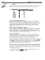
ALL-CALL PAGING
ACCESS DENIED
All-call paging allows all stations to receive
announcements through the station speaker at once.
All-call paging is also sent to the paging port where it
can be applied to the input of an external paging
amplifier. Origination of announcements must be via
the station handset. Each station can be programmed
to receive and/or originate all-call page. The ability to
receive and originate all-call paging at a station is
enabled by station class of service programming. Also
see the discussion titled: Zone Paging.
Access to particular lines can be denied at certain
stations in the system through system programming.
A station user cannot select a denied line for use.
This feature is programmable on a per line/per station
basis in station class of service programming.
ACCOUNT CODE BUITON
Station class of service programming can be used to
assign an Account Code button to any programmable
button location at a station as part of the button
mapping procedure. With this Account Code button
available, the user can press it and then dial the
account code without interrupting the call. Only the
user of the Account Code button will hear the DTMF
tones when the code is dialed. The distant on-line
party will not hear the DTMF tones, and the line will
not be placed on hold. The distant on-line party can be
heard while the account code is being dialed.
AREA PAGING INTERFACE
Refer to the discussion titled: ExternalPaging
Interface.
ASSIST Bull-ON
This feature allows a station user to program a button
to be used for sending a message to an LCD
speakerphone. Once programmed, the station user
can press the ASSIST button at anytime and then
press a DSS button to sound a tone burst at the called
station and present a preprogrammed message in the
station display. A message can be sent while on a call
without alerting the distant party. This feature is useful
for requesting assistance while engaging on a call. For
example, a customer service representative could
request assistance from a supervisor while talking to a
problem caller. The supervisor, upon receiving the
tone and noting the display message, could perform
an executive override or service observing action to
join the call or monitor it.
ACCOUNT CODES WITH
POSITIVE VERIFICATION
Specific account codes can be assigned by station
users to specific types of calls. The account codes
are used by the system to identify calls by category, or
special grouping, for call recording purposes. All calls
with the same account code will be reported together
by the station message detail accounting feature.
The system may be programmed to verify the user
entered account code and sound an ermr tone if it is
incorrect. The system may be programmed by call
costing and SMDA reporting class of service
programming to permit station users to enter account
codes for incoming calls and/or out going calls if
desired. Account codes are entered while on line
either before an out going call is dialed or after the
distant patty on an incoming call has hung up. On out
going calls, the user who enters the account code is
associated with the call record except when the call is
AUTOMATIC CALLBACK
If a busy tone is encountered after an intercom station
is called, a special code number can be dialed that will
cause the system to automatically ring the calling and
called stations when the called station becomes idle.
2-l
IMI 66-083
-rVI @on Of System Features
No class of service programming is required to enable
this feature.
use of the add-on conference feature. In the
non-private mode, another station with that line
appearance can gain access at the same time
(sometimes known as common line pickup). A line is
specified as private or non-private through the line
class of service programming. Through station class
of service programming, a line can be made
non-private at a particular station. Also see the
discussions titled: Conference - Add-On and Privacy
Release.
AUTOMATIC DIALING
The system supports up to 22 auto dial positions per
station. Autodial buttons can store up to 16 digits plus
an intercom or line selection. Stored digits include
9-0, ++ and #. A pause is stored at any point where the
HOLD button is pressed, and a hookflash is stored at
any point where the TAP button is pressed. Automatic
dialing can be used to provide one-button access to
system features. No class of service
programming is required to enable autodialing. Also
refer to discussions titled: Automatic Pause Insertion,
Station Speed Dial, and Programmable DSS/BLF.
AUTOMATIC HOLD FOR INTERCOM
If the second intercom line is selected while a call is
active on the first intercom line, this feature causes the
first intercom call to be automatically placed on hold.
Station class of service programming is required to
enable this feature.
AUTOMATIC HOLD - TRANSFER TO
INTERCOM (ANSWER HOLD)
If the intercom line is selected while an outside line
call is active, this system feature causes the outside
call to be automatically placed on hold. No class of
service programming is required to enable this feature.
AUTOMATIC REDIAL OF BUSY
NUMBER OR UNANSW i RED CALL)
A busy number or unanswered call can be
automatically redialed by activating this feature. Once
automatic redial is activated, the station will select the
line, automatically dial the number, and wait for a
response. It will do this once a minute for
approximately 10 minutes unless deactivated because
that button or another button is pressed or the handset
is lifted. The feature cycle is timed and does not have
busy detection circuitry. Because of this, if operating
handsfree when the called party answers, the handset
must be taken off-hook to prevent the caller from
being cut off by the timing cycle. Automatic redial is a
designated programmable button position and must be
programmed by the user to be active but no class of
service programming is required.
AUTOMATIC STATION RELOCATION
With this feature, the system will automatically
recognize a particular station should that station be
relocated to a new station port. When installed at the
new pori location, the station will continue to provide
the same class of service parameters and respond ta
the same extension numbers as it did at the original
station port. This system feature is enabled with
system class of service programming.
AUTOMATIC HOLD - TRANSFER TO LINE
This system feature is made available through
programming to selected stations. When enabled,
pressing any line button will cause an active line to
automatically go on hold. This feature allows a user to
move from line to line without having to press the
HOLD button to place any current calls on hold.
Station class of service programming is used to
enable this feature at the desired stations.
AUXILIARY EQUIPMENT INTERFACE
A non-key system telephone device or a data device
can be connected to a line ahead of the common
equipment by using the auxiliary equipment interface.
The system can detect an off-hook condition in the
device connected to the auxiliary equipment interface,
and turn on the status light for that line at the button
system telephones. tt does this to indicate that the
line is busy and not available for station use. Auxiliary
equipment interface connections provide connections
to lines 2 and 4. Pressing the line button on a system
station cannot interrupt an external device unless the
line has been programmed to be non-private.
AUTOMATIC PAUSE INSERTION
When the system stores a dialed number for later
redial, it automatically stores a pause whenever the
user watts between digits for at least two seconds.
The automatic pause is inserted in the stored number
sequence at the point where the manual pause in
dialing occurred. The length of the pause is fixed at
two seconds by the system.
AUTOMATIC PRIVACY
A line can be made private or non-private through
programming. In the private mode, a station has
exclusive use of the line during a call. No other Station
can access that line unless it is included through the
AUXILIARY RINGER INTERFACE
The auxiliary ringer interface provides “dry-contact”
relay closures which track the ringing pattern
2-2
Description Of System Feat!
lMl66-083
activated when station port 17 rings or when ringing
sent to the paging port.
iS
When programmed for station port 7 7 ringing, an
external device is often used to provide loud ringing.
When programmed for paging port ringing, an external
paging amplifier is usually employed. The system
supplies ringing tones to the paging port along with the
relay closures. The ringing tones can be sent to the
input of an external paging amplifier. The relay
closures can be employed to energize the paging
amplifier while the ringing tone is being sent to it.
System class of service programming is used to
choose either the paging port. or station port 17 for the
ringing port relay control. System class of service also
determines the type of ringing sent to the paging port.
Station class of service programming determines the
type of ringing sent to station port 17. Also refer to the
discussions titled: Common Audible Ringer /fIrerfaCe
and External Paging Interface.
BACKGROUND MUSIC EXTERNAL
MUSIC SOURCE RE 6 UIRED)
If an external music source is provided, background
music can be turned on and off at individual stations.
The loudness of the background music is adjusted with
the call monitor speaker volume control, and the
background music automatically turns off during calls.
No class of service programming is required to provide
this feature. Also refer to the discussion titled: External
Music Source.
BASIC KEY SERVICE (lA2) EMULATION
The system provides all of the basic, 1 A24ype, button
service features. These features are: selective line
pickup, common line pickup, muftiline pickup, and
hold. No special class of service programming is
required.
BATTERY BACK-UP
(CHASSIS, CABLE, AND BATTERIES)
Battery back-up assemblies including chassis, cable,
fuses, and batteries are offered as optional kits
(available from Comdial). The assemblies are
designed to connect directly to the unintenuptable
power source (UPS) interface located on the common
equipment chassis. No user intervention is required
with this feature, and no class of service programming
is required.
BAlTERY BACK-UP INTERFACE
Provision has been made for attaching a Comdial
provided optional battery back-up kt to give full
uninterrupted system power in case of an AC power
loss. The switching and charge circuitry are in the
common equipment, while batteries, chassis, and
cable are packaged as a separate option. When
plugged into an active AC power source the common
equipment will constantly charge the attached
batteries. Built-in circuitry automatically switches to
battery power when AC power is lost. Wrth batteries at
full charge, a fully loaded system will operate for a
minimum of one hour without AC power.
BLOCK PROGRAMMING
A class of service assigned to a particular station or
line can be assigned to an entire block of stations or
lines with one programming action. This feature
eliminates the need to individually program stations
and lines wfth the same class of service. Block
programming class of service can be performed after a
station class of service or line class of service has been
programmed for a particular station or line.
CALL ANNOUNCE WITH HANDSFREE
ANSWERBACK
The internal speaker at each station provides
call-announce capability over the intercom link. A
handsfree response to a call-announce call can be
made. This response is transmitted by the microphone
built into the telephone housing..
CALL COSTING AND STATION MESSAGE
DETAIL ACCOUNTING REPORTS
The system provides buift-in, estimated costing of all
outside calls. tt also provides station message detail
accounting (SMDA) printout reports of all costed calls
as well as displayed call costs on LCD speakerphones.
’
Call costing, in general, provides a means of
establishing costs to be applied to outside calls made
from system telephones. Call costing computes
charges for a call after it is completed. lt does not
restrict dialing as toll restriction does. Call costs are
based on a two-tier time rate and includes a line
surcharge cost. Allowances can be programmed for
call set-up and minimum call duration. The system
provides several ways of determining call costing
making it is possible to apply reasonable rates for the
entire country.
The system is arranged to automatically provide a
report whenever the costed call storage reaches 95
percent of capactty. Additionally, programming can be
effected that causes these reports to be printed
automatically at a specific time of day.
There are five different SMDA reports which can be
produced:
2-3
IMI 66-083
_-, +ion of System Features
Detailed report sorted by stations
l
Detailed report sorted by account codes
0 Line summary report
l
Department summary report
l
A general output of all records
l
Upon completion of report printing, all records used for
the reports can be deleted. Any call records created
between the time the report printout was started and
completed will not be deleted. If the reports are not
deleted after they are printed, a later command to
delete records will delete all records at that point and
not just the ones that were printed in the previously
generated reports. Programming action can be taken
to always delete the records after they have been
printed. The attendant has the ability to request
particular reports to be printed at any time they are
required.
Account codes can be established to allow system
users to identify calls by category or by any other
desired grouping so that costing by that category or
grouping can be reported. Department numbers can
be defined and stations assigned to different
departments so that call cost reports can be produced
on a department-by-department basis.
Feature programming is provided in call costing and
SMDA Reporting class of service programming.
Stations are assigned to specific SMDA departments
through station class of service programming. The
LCD speakerphone display of costed calls is also
enabled through station class of service programming.
CALL FORWARDING ON ALL CALLS
This feature allows a station user to designate another
station or the attendant station as the recipient of all
calls normally directed to ring at the user’s station. If
enabled when night transfer of ringing is activated, the
night ringing assignment of the station is also
forwarded. Calls that are forwarded to a recipient
station can be forwarded again from that station to
another station. Thus, two levels of call forwarding on
all calls can occur, first, from station A to station B
and then, from station B to station C. For each
intercom call that is received while calls are forwarded,
a short tone burst will occur at the user’s station as a
reminder that call fotwarding is enabled. When a
programmable button is programmed to serve as a
call forward button, the associated LED will turn on
when the button is pressed to indicate that the feature
is enabled. If the call forward button is programmed as
a second level to a DSS/BLF button, the LED
indication is afways reserved for BLF indication. On
LCD speakerphones that are recipients of call
forwarding, the display will indicate the extension
number or station name for the station from which an
intercom call was forwarded.
CALL FORWARDING - PERSONAL
Call forwarding on intercom allows a station user to
designate another station number (or the attendant
station number) to be the recipient of intercom calls
normally directed to that user’s station. For each
intercom call received while call forward is enabled, a
ring reminder (short tone burst) will be sounded at the
forwarding station to remind the user that the calls are
being forwarded. On LCD speakerphones that are
recipients of call forwarding, the display will indicate
the extension number or station name for the station
from which an intercom call was forwarded.
CALL PARK
The call park feature is similar to a manual hold
condition. A call that is parked from a particular
station can be retrieved at any station in the system by
dialing the appropriate access code. (Note: the
retrieving station cannot have access denied to the
line on which the call appears.) Calls are parked and
retrieved within the system through the use of dialing
codes. The system provides nine parking circuits
(orbits). Call park, when used with the paging
features, allows a system attendant to direct calls to
roving personnel. A call that is left in a parking orbit
for preprogrammed length of time automatically
returns to a timed hold recall condition at the station
which originally parked the call.
CALL PICKUP - DIRECTED
A station user can dial a code, followed by the
extension number of a ringing station, to answer the
ringing call.
.
CALL PICKUP - GROUP
If a call rings to any station in a pre-programmed
group and another user in the group wishes to answer
the call, that user must dial the group pickup code to
answer the call. Four different groups can exist with
any number of stations in a group. Overlap is provided
by allowing stations to be in more than one group thus
enabling those stations to pick up for stations in more
than one group. Stations within the system are placed
in logical answering groups by programming action.
Group stations together using the station class of
service programming.
CALL TRANSFER -SCREENED
Screened call transfer allows outside calls to be
transferred from one station to another, via the
intercom link, in one of two ways. If both stations have
access to the line, a common line pickup transfer can
2-4
Description Of System Feat1 P
IMI 66-083
be effected. If the other station does not have access
to the incoming line, transfer can still take place using
the system transfer feature. For a screened transfer,
a call is transferred to another station with a
pre-transfer announcement by the transferring patty.
Transferring calls is accomplished with the
TRANSCONF button. Also refer to the discussion
titled: Call Transfer- Unscreened.
CALL TRANSFER - UNSCREENED,
An active call can be transferred to another station
without being announced. The transferred call will
camp-on to the other station where it will ring and
await an answer. The call will automatically ring back
to the transferring station after a programmable recall
period. There is no limit as to how many calls can be
camped onto another station. A transferred call will
only ring if the station is idle. The system class of
service programming determines the recall time for an
unanswered transferred call.
CALL WAITING TONE
The call waiting tone may be signalled to a busy
station to indicate that another station or the attendant
wants to contact the busy station. A special code is
dialed to activate the tone.
CALLING STATION
IDENTIFICATION ON BLF
If the station number of a calling station has been
programmed into the direct station select/busy lamp
field (DSS/BLF) of a called station, the caller will be
identified by flashing at the corresponding BLF light.
The lights also indicate the status of the DSS
telephones: dark = idle, steady-on = in use, flash =
calling (or ringing when station monitoring is enabled),
and flutter = call back request (if feature is available.
No class of service programming is required for this
feature. Also refer to the discussions titled:
Programmable DSS/BL F and Call Messaging.
CLASS OF SERVICE PROGRAMMING
(FROM MAIN STATION)
Class of service (COS) programming is used by the
installer to configure and assign all system, line,
station, and special purpose operating features. The
installer enters COS programming by dialing an
access code over the intercom line. System
administrators can enter COS programming with
another code to reprogram any system, station, or
special purpose operating feature that may require
change at a later date. Line reprogramming abifiiy is
not available through system administration
programming. The system attendant can reprogram
certain system-wide features that require periodic
change by entering COS programming with another
code provided for this purpose. The station user can
program individual stations for speed dial, autodial and
direct station selection (DSS) by entering COS with a
code provided for that purpose. Thus, COS
programming is arranged with a hierarchical order
from the highest (the installer) to the lowest (the
station user) level wfth a higher level programmer
having the ability to do anything a lower level
programmer can do without exiting a current
programming mode. However, only the station user
can program the speed dial and autodial locations at
telephone.
All class of service (COS) programming is performed
from station 10 or 12. Any station and console
combination will function in this mode and provide
visual feedback with the LED associated with the
programming button. By employing an LCD
speakerphone, however, the programmer will have the
benefit of display prompts and verifications to simplify
and clarify the programming procedures. Class of
service programming access is as follows:
l
Installer dials: ITCM % # 7 4 6 +K
l
Administrator dials: ITCM +++ # 2 3 6 +I+
l
Attendant dials: ITCM % # 0
l
User dials: ITCM +# +
Class of service programming can be performed using
instructions provided in Chapter 4, Sections 2,3 and 4.
CLASS OF SERVICE PROGRAMMING
(VIDEO DISPLAY TERMINAL)
An asynchronous, serial data terminal with an RS-232
interface can be used to effect class of service
programming through menu-driven procedures. VDT
programming provides a menu-driven approach to
programming as discussed in Chapter 4, Section 5.
CLASS OF SERVICE
PROGRAM PRINTOUT
Connection terminals are provided to interface an
RS-232 compatible, asynchronous serial data printer
to the system. The connected printer will provide a
printout of class of service and toll restriction records.
The data prlnter service class of service programming
determines the nature and extent of each requested
printout. The system class of service programming
specifies the bit-length and baud rate of the data.
COMMON AUDIBLE
RINGER INTERFACE
Connections are available at the wmmon equipment
that provides “dry-contact” relay closures whenever an
incoming line rings. These contact closures track the
ringing pattern and can be used to control an external
2-5
8.
lMl66-083
__, ,,.rtion Of System Features
DELAYED RINGING
CONFERENCING - ADD-ON
With this feature, a station, operating in a private mode,
can add up to four other stations to an outside call.
CONFERENCING - MULTILINE
This feature will allow one station to access up to four
outside lines at the same time resulting in a conference
arrangement. Conferencing is established through the
use of the TRANSKONF button.
,
CONFERENCING - UNSUPERVISED
After a conference between an internal party and a
maximum of two external parties has been
established, this feature allows the internal party to
drop out of the conference by dialing a special code.
The conference between the two outside parties
continues in an unsupervised condition.
Also refer to
the discussion titled: Conferencing - Multiline.
Pinging assignments are programmable. A station can
be programmed to provide delayed ringing on some
lines while providing immediate ringing on other lines.
Delayed ringing is assigned to certain lines at each
station through station class of service programming.
DEPARTMENTAL CALLING
DISTRIBUTION REPORT
The attendant station can request a Departmental
Calling Distribution (DCD) report. The DCD report will
provide a compilation of department call activity. The
statistics that are reported are based on the
department assignments that are active at the time of
the report and are extracted from the SMDR records
collected by the system. For a report to be generated,
a department must exist. All calls that are included in
the DCD report, must meet the following conditions
before they are reported as department calls:
DATA SECURITY
They must be incoming calls. Outgoing calls are
not reported in the DCD report.
This data security feature will prevent any type of tone
(DTMF, camp-on, barge-in, etc.) from interrupting a
call that is active on a port programmed with the
feature. This prevents interference to non-voice
communications from occurring when the port is being
used as a data port (when operating a modem through
an OPX port for, example). Use station class of service
programming to enable a data security port.
The port number of the line which received the
call must be one that is assigned to a department.
The port number of the station which answered
the call must be assigned to a department.
l
DEFAULT FUNCTIONAL PROGRAM
At initial power-up of the system, the operating features
are set to a specific group of operating conditions
(defautt conditions). The defautt conditions provide a
complete operating system for normal use. tt can be
left as a defautted system or reprogrammed as
desired. Defauft conditions can be reset if desired. A
system can be defaufted by system, line, and station
class of service programming. A master clear will
defauft the entire system and erase all stored
programmable button information.
DEFAULT TOLL RESTRICTION
Two toll restriction tables are defaulted with
pre-programmed values and are pre-assigned to all
lines. The tables need only be assigned to the stations
by programming action to put them into effect. The
defaulted tables can be reprogrammed with different
information using the normal programming procedure.
Assign toll tables to stations using station class Of
service programming. Reprogram toll tables using toll
restriction table configuration class of service
programming.
2-6
A DCD report consists of the following columns
of information:
Station Number: The station name or extension
number of the station being reported.
Idle Tlme: The amount of time that the station is
’
on-hook and available to answer a call.
Dept. Calls: The amount of time spent on
incoming calls that rang into the department and
calls that were transferred to the department.
Hold Time: The amount of time that department
calls spent in an on-hold state at a particular
station.
Avg. Dept. Calls: The average time per call
(including on-hold time) that a station spent on a
call.
WrapUpTIme: The time that a station spent in a
wrap-up mode doing such things as follow-up
paperwork. While a station is in a wrap-up mode,
it does not receive department calls. The station
user sets a wrap-up mode by pressing SHIFT
DND and repeats the procedure to clear the
wrap-up mode.
Missed Calls: The total number of calls that are
not answered at a station and that are cycled by
the system to another station for answering
lMl66-083
Other Calls: This is a summation of the time
spent on outgoing call activity, incoming call
activity on non-department lines, plus all intercom
call activity.
On-Duty Time: The on-duty time includes a
summation of idle time, department call time,
wrap-up time, and other call time.
Off-Duty Time: The time that a station spent in a
do not disturb mode. While in a do-notdisturb
condition, a station is not available tc receive
calls. The station user sets a do-not-disturb
mode by pressing DND and repeats the
procedure to clear the do not disturb mode.
UnansweredCalls: Total number of calls that
went unanswered at a department.
Calls Answered After 36 Seconds: Total
number of calls that waited at least 36 seconds
(approximately six rings from the CO) before
being answered.
Calls Handled By Overflow Station: Total
number of calls that were answered and
transferred by the overflow station and then
answered and serviced by another station.
Calls Terminated At Overflow Station: Total
number of calls that were received by the
overflow station and were either answered but
not transferred or were dropped by the caller
before being answered.
Also refer to the discussion titled: Direct Department
Calling with Departments Call Distribution (DCD).
DESIGNAT;;tIK?d&AMMABLE
Station programmable buttons can be assigned to
provide one-button access to a broad range of
features. There are designated buttons that must be
assigned at each station using station class of service
programming but the auto rediai button and response
message button are designated programmable
buttons that can assigned by the station user.
DIAL 0 FOR SYSTEM Al-l-ENDANT
The system attendant station (station 10) is signalled
whenever the digit 0 is dialed on the intercom line.
DIRECT DEPARTMENT CALLING
WITH DEPARTMENTAL CALL
DISTRIBUTION (DCD)
Direct department calling has been enhanced wtth
departmental call distribution (DCD) and provides a
means by which outside lines can be assigned to one
of four different departments. Calls received on
department lines and calls that are transferred to a
department from within the system search for an idle
station in that department. Department calls are
distributed evenly throughout the department stations
Description Of System Feat.
for answering with individual stations having the ability
to be taken out of service as necessary. Calls received
on department lines and calls that are transferred to a
department from within the system are placed in a
queue for servicing. New calls, transferred calls, and
held calls are all assigned a time stamp by the system
so that they will be serviced in the order of their arrival.
Up to four departments can be formed with up to 16
stations (plus one overflow station) allowed in each
one. A station can be assigned to more than one
department, if desired. Since a station can be
assigned to more than one department, the attendant
station can be added to serve as the overflow station
for all departments if desired. Separate pilot numbers
(extension numbers) can be assigned to each
department to be used for making intercom calls or
doing call transfers to the department.
The direct department calling feature requires that lines
and stations be assigned to a department. It does not
require that department lines be assigned to to appear
at buttons on department stations. If direct line
appearance of a particular department line to a
particular department station is required, it can be
assigned. If this assignment is made, ensure that
neither direct nor delayed ringing is enabled for that
line at that station.
An incoming call searches for the first station available
to answer a call. lf all stations in a department are
busy or are ring no-answer (RNA), the call will go to
the overflow station in that department (if one has been
programmed). lf there is no overflow station
programmed, the call continues to try the department
stations until tt is answered or dropped by the caller.
The caller continues to receive ringback tone until the,
call is answered. The overflow station can service the
call or transfer it back to the department using the
department pilot number. When the call is transferred
back to the department by an overflow station, it will
not return to the overflow station until that station is
idle and has no ringing calls either new or transferred.
instead, the call will campon at the department and
walt for a station to become idle. The caller will receive
music while on hold if the system is so equipped. To
provide reassurance to the caller during ringing it is
recommended that a music source be connected to
the system. The call will remain in a held state until it is
answered or until the department transfer recall
timeout period has ended. When the recall timeout
period has ended, the call will return to the transferring
station.
Intercom calls that are made to the department will test
the department stations for busy or a RNA If all
stations are busy, a busy tone is returned to the caller.
Intercom calls will not camp-on at the department but
will go to the overflow station.
,&Ion Of System Features
Further, the system camp-on feature cannot be used
to camp-on to a department.
Subsequent calls to a department on a particular line
always try the next station in the department from
whichever station serviced the last call on that line.
This means that if department stations 15 and 16 are
programmed to answer line 1, and station 15 services
a call, the next line 1 call will ring at station 16. When
both stations 15 and 16 are programmed to answer
lines 1, 2 and 3, call delivery is on a per line basis: If
station 15 handles and completes calls on line 2 and 3
while station 16 is still on line 1, the next calls on line 2
or 3 goes to station 15 even if station 16 has become
idle.
Since the RNA time of a station is a programmable
feature, department stations can be set to have a short
RNA time to allow a call to search rapidly through a
department for an answer.
When an outside or transferred call is ringing at a
department station, the station user can press the
pre-programmed Do Not Disturb (DND) button to
place the station in an off-duty condition. While
off-duty, all outside and transferred calls skip to the
next department station. This offduty condition
remains set until the DND button is pressed again to
place the station back in service. When the overflow
station is set to DND, all incoming and transferred calls
will return to the department queue.
A department station can also be taken out of service
and placed in a wrap-up mode to provide the user time
for doing such things as follow-up paperwork. While a
station is in a wrap-up mode, all outside and
transferred calls skip to the next department station.
The station user sets the wrapup mode by pressing
SHIFT DND and presses these buttons again to clear
the wrap-up mode.
It should be noted that the departments formed for use
with this direct department calling feature are different
from those departments used in SMDA reporting.
Assign department transfer recall time (unanswered
call transfer recall time feature) using the system class
of service programming. Assign lines for direct
department calling using the line class of service
programming. Assign department stations, access
codes to departments (flexible numbering feature), and
busy/RNA timeout (call forward - busy feature) using
the station class of service programming. Also refer to
the discussion titled: Departmental Calling Distribution
Report.
lMl66-083
DIRECT INWARD STATION DIALING
(DISD)
The DISD feature allows an external party to call an
intercom station directly without assistance by the
attendant. The DISD call must be received on a line
which has been specially programmed to allow this
feature. Any line can be programmed to be a DISD
line for both the normal mode of operation and the
night transfer (of ringing) mode of operation.
The number of rings which occurs on a DISD line
before tt is answered is programmable. By setting a
large number of rings, time is allowed for a call to be
serviced in a regular manner by stations that have a
line appearance for the DISD line. Setting the number
of rings to 0 disables the line for DISD use. If a line is
to be dedicated for DISD use, tt is a good practice to
set ft for one ring. The amount of time allowed for an
extension number to be dialed is programmable and a
DISD assist station can be programmed to answer
calls that are not completed during this dial time limit.
When a DISD line is called, it rings for a programmed
number of rings. If the call is not answered in a normal
manner by a station with the line appearance during
this time, the system answers it and presents a DISD
dial tone to the caller. The s;:stem then waits for an
extension number to be dialed from the calling
telephone. Only one DISD line is serviced at a time;
therefore, an incoming call could ring for more than the
programmed number of rings if a DISD call is being
serviced when a second DISD call is received.
When a valid extension number is dialed, a
confirmation tone is sounded, the system attempts a
transfer, and the called station rings if it is idle. If a
called station does not answer within the transfer recall
timeout period, the call is returned to DISD dial tone. If
the called station has the call fonnrard feature set, the
forwarded station rings. lf a called station is busy, the
call is placed on hold and camped-on at the busy
station. ff the camp-cm is not answered within the
transfer recall timeout period, a busy tone is given
followed by DISD dial tone. The system will return the
caller to DISD dial tone two additional times and then
drop the line (a total of three attempts are made).
NOTE:lf the busy called station is part of a hunt group,
the DISD call is muted to an idle station in the hunt
group. lf no idle stations are found, the call is
catqoed-on at the dialed station. The hunt group is
not followed in the case of a ring-no-answer (RNA).
If an invalid extension number is dialed, an error tone is
sounded before the DISD dial tone is returned. If a
mistake in dialing is made, the caller can dial a S for a
new DISD dial tone. The system will return the caller to
DISD dial tone two additional times and then drop the
line. If extension number dialing is not completed
within the programmed dial time limit, the call is routed
Description Of System Feats
lM166-083
to the DISD assist station if one is programmed;
otherwise, the line is dropped. If the assist station is
busy (call will camp-on at the assist station) or lf the
assist station does not answer before the transfer recall
timeout period, the system will return the caller to DISD
dial tone. If extension number dialing is not completed
within the dial time limit this time, the line is dropped.
It is recommended that a music source be connected
to the system to provide a reassurance to the caller
during a camp-on situation when the DISD feature is
being used.
DIRECT STATION CALL
HOLD (STATION PARK)
This feature allows a station user to park a call at a
specific station where lt will be held without ringing. A
feature code plus a station extension number can be
dialed over the intercom line to park the call or a
programmable button can be programmed to provide
a “directed hold” to a specific station. The parked call
is picked up by directed station by dialing a feature
code. It can be picked up at any station through the
use of the call pickup feature. No class of service is
required. Also refer to the discussions titled: Call
Pickup - Directed and Call Park.
DIRECT STATION SELECTION (DSS)
PROGRAMMABLE
Refer to the discussion titled: ProgrammableDSSlBLF.
DISTINCTIVE RINGING
The ringing cadence of an incoming call is the same as
the ringing cadence of theTELC0, PBX, or CENTREX
system. The ringing cadence of an intercom call
presents two tone bursts sounded every four seconds.
DO NOT DISTURB
Any station can be set to a do-not-disturb mode (DND)
using the designated DND programmable button and
associated indicator (indicator will light when DND is
active). While in the DND mode, the station will not ring
on any incoming call nor will it accept an intercom call.
A party making an intercom call to a station set in the
do-notdisturb mode hears a fast busy tone. The
feature cannot be overridden by the calling party
unless the override feature is enabled. The DND
feature is used with the departmental calling feature to
provide a station wrap-up mode and a station off-duty
mode. Refer to the discussions tftled: Do Not Disturb
Override, Executive/AttendantOvertide,
and
Departmental Calling Distribution Report.
DO NOT DISTURB INHIBIT
The system can be programmed to inhibit any station
from entering the DND mode. System class of service
programming is used to program this feature.
DO NOT DISTURB OVERRIDE
Stations can be provided with DND override capability
which will allow them to call a station that is set in the
DND mode. The Executive/Attendant Override feature
must also be active for DND override feature to
function. Station class of service programming is used
to assign this feature. Also refer to the discussions
titled: Do Not Disturb and Executive/Attendant
Override.
DUAL INTERCOM
This feature provides for two separate intercom lines at
the same station. One intercom line is fixed and is
accessed with the ITCM button. The other intercom
line is programmable and is accessed by a
programmable button selected for that purpose by
class of service programming. Calls are handled on
the intercom lines in much the same manner as
outside calls are handled using the line buttons.
Special considerations are as follows:
Distant party hang-up causes intercom link to drop.
Intercom call to station already busy on intercom
rings in subdued fashion and flashes indicator
associated with other intercom button.
With both intercom lines busy, a third intercom call
resufts in a secure off-hook voice announce (if
enabled) at busy station.
Pressing a DSS button while on an active intercom
call will drop the distant party unless the automatic.
hold feature is enabled for the intercom line
through class of service programming. The hold
button can be used, however, to place an intercom
call on hold before selecting the other intercom
line for use.
Any action taken on the intercom by a station
being observed via the service observing feature
will cause the observing station to return to an idle
state.
The station class of service button mapping procedure
assigns a programmable button to serve as the second
intercom button.
DYNAMIC LINE BUlTONS
Through class of service programming, certain idle line
buttons can be arranged to serve as dynamic line
buttons. This feature allows the system to temporarily
assign a line to a station that normally does not have
the line assigned to it, and have that line appear on a
dynamic line button. While the call is appearing on the
dynamic line button (LED on), any normal call handling
lMl66-083
..tron Of System Features
operations can be performed. Station class of service
programming allows certain buttons to be
programmed as dynamic line buttons
line class of service programming arranges a line port
for external paging interface.
FEATURE INHIBIT
END-TO-END SIGNALLING
ON INTERCOM
After an intercom call has been established, the system
can continue to send dialing signals (DTMF tones)
through the intercom path. This feature can be
performed from every station in the system, and is
s
used by peripherals such as voice mail equipment.
After an outside call has been established, the system
can continue to send dialing signals (DTMF tones)
through the telco network and have them received at
the distant end for inward call completion (bank by
phone, etc.). This conventional, off-hook dialing
feature can be performed from every station in the
system.
EXCLUSIVE HOLD
Exclusive hold prohibits a held call from being
retrieved by any other station. The exclusive hold
condition also links the held call to the timed hold
recall timeout feature. After timeout, audible and visual
signalling will occur and the exclusive hold condition
will revert to a normal line hold condition.
EXCLUSIVE HOLD SYSTEM-WIDE
ENABLE/DISABLE
This feature allow systems that do not require
exclusive hold capability to have it turned off
system-wide through programming. System class of
service programming is used to enable or disable
exclusive hold.
EXECUTIVE/ATTENDANT
OVERRIDE
This feature allows the user of a station, upon
encountering a busy signal at another station, to dial a
code that will override the busy signal of a call, sound
a warning tone, and allow access to the existing
conversation. This feature is enabled through station
class of service programming.
A large array of individual features can be disabled
system-wide to provide a basic telephone system. A
basic telephone system is useful for installation
environments where a large proportion of the stations
are accessible to unauthorized users thus subject to
tampering or for environments where station users
must be limited as to the variety of features allowed to
them. Features are disabled by system class of
service. Once disabled, they can enabled by turning
on all features at once using the system default
programming.
FLEXIBLE RINGING ASSIGNMENTS
Ringing assignments are programmable on a per
station/per line basis. Pinging can be controlled for
every line that has an appearance at each station.
Delayed ringing is assigned to certain lines at each
station through station class of service programming.
Refer to the paragraph titled: Delayed Ringing.
FLEXIBLE RINGING
ASSIGNMENTS OF PA PORT
The PA port can be programmed for flexible ringing
assignments and zone pages. Any desired lines can
be programmed for direct ring, delay ring, or night
transfer (of ringing) at this port. Paging can be to
programmed zone or to allcall. A speaker can be
connected to the PA port to sound the ringing that is
generated by the system and sent to this port and
paging announcements when they are sent to the
programmed zone. Using such an arrangement, it is ’
possible for a user to determine that certain lines are
ringing, such as in a night transfer (of ringing) mode,
and go to the nearest telephone and answer the call.
The most common use for this arrangement is as a
night bell eliminating the need for external equipment
as required with the common ringer and auxiliary
ringer interface. The speaker cannot be used for voice
response as the path is one-way only. Use system
class of service programming to assign ringing and
paging to a PA port.
FLEXIBLE STATION AND LINE
CLASS OF SERVICE CONTROL
EXTERNAL PAGING INTERFACE
A dedicated paging port or a spare line port can be
interfaced with an external paging amplifier. The
paging amplifier can then be dial-accessed by stations
in the system. DTMF tones can be dialed through the
line port to provide zone selection if provided by the
external paging amplifier. The dedicated paging port
does not support any “talk-back’ capability even if such
a feature is provided by the external equipment. The
The extension number of a station and all other
programmable attributes that are initially assigned to a
particular station port and the line, along with all
programmable line attributes that are initially
connected to a particular line port can be re-assigned
to a different port through programming action. This
feature allows adds, moves, and changes without
2-10
Description Of System Featf
lMl66-083
re-locating the station and line wiring. Line and station
class of service programming are used to reassign
stations and lines. Also refer to the discussion titled,
Auxiliary Ringer Interface.
FLEXIBLE STATION NUMBERING PLAN
The system supports a flexible station numbering plan
for individual stations. Each station can be
programmed to respond to the dialing of any available
number between 10 and 7999. This feature may be
used to match the calling number of a station located
in a pre-numbered area to that area number. A
combination of two, three, or four digit extension
numbers can be assigned as long as they do not
conflict. For example: If 21 is assigned as an
extension number, there can not be any other
extension number assigned that begins with a 21. The
system class of service programming is used to assign
extension numbers to individual station ports.
FULL BUlTON
PROGRAMMABILITY OF FEATURES
Most digital communication system features can be
made available at programmable buttons by
programming the specific access codes necessary for
dialing the features. Programmable features include
those that can utilize lamp (on/off) supervision (e.g.,
call park orbits). All feature access codes can be
stored, except for those requiring TRANSKONF
button action. Continuous strings of digits can be
stored, including ITCM button presses, up to the
maximum amount of storable digits allowed in an
autodial entry (16).
HANDSFREE ANSWER INHIBIT
The MUTE button on a station can be used to block all
handsfree answerback
response. This arrangement
will prevent a station user from monitoring another
station site using the monitoring ability of the voice
announce feature. When the button is pressed, all
handsfree answerback is disabled thus inhibiting any
off-site monitoring. The MNlR (SPKR) light will flash to
indicate that this feature is active. Also refer to the
discussion titled: Mute.
IDLE LINE PREFERENCE
When a station is programmed for idle line preference,
it will automatically be connected to the first assigned
idle line. The system can be programmed on a per
station basis to enable idle line preference. When idle
line preference is enabled, taking the handset off-hook
will automatically connect the station to any assigned
line that is idle and has been arranged for this feature.
The line button will not have to be pressed. If this
feature is used in conjunction wfth prime line
automatic, the user will be given prime line first when
going off-hook. An idle line will be given if the prime
line is in use. The station class of service
programming enables this feature on a per station/per
line basis.
INTERCOM CALL PROGRESS TONES
Intercom call progress is marked by special tones. A
steady tone is provided for dial tone. Ring-back tone is
one second on and three seconds off. For tone
signalled intercom calls, a two-tone burst is sounded
every four seconds at a called station and returned to
the caller as ring-back. For a voice signalled intercom
call, a single tone burst is sounded at a called station.
When a called station is busy, a busy signal of one-half
second on and one-half second off is received at the
calling station. A fast busy tone will be supplied when
the called station is in the do not disturb mode. OPX
ports are only supplied with the regular busy tone
since fast busy tones could interfere with the operation
of some accessories that can be connected to this port.
INTERCOM HUNT GROUP
Station ports can be assigned to intercom hunt
’
groups. When a station that is assigned to a hunt
group is busy or is a ring-no-answer (RNA), a call to it
will ring at the next idle station in the group. A hunt
group can be terminal or circular. A call will route down
a terminal group from the called station until it finds an
idle station or reaches the end of the group. A call will
search around a circular group until it encounters an
idle station or until all stations in the circular group are
searched. The ringing time at any one station is
programmable. Hunt groups are created through
station class of service programming.
I HOLD AND I USE INDICATIONS
The light associated wtth a line button provides a visual
indication of the status of that line. When a station user
has a line in-use or on-hold at a station, the light
indication provided at that station is of a diierent flash
rate than the indication provided at the other stations
in the system. No class of senrice programming is
required.
INTERCOM LINE TIMEOUT
Should the intercom line be selected with no dialing or
other action taking place, the intercom will timeout
after ten seconds, and return to an idle state.
LAST NUMBER REDIAL
Each station is provided with a last number redial
feature. This feature will save 32 digtts of the last
outside number dialed. A newly dialed number will
2-11
lMl66-083
-. #,.&on Of System Features
always automatically replace a previously dialed
number. Upon command, the system will choose a
Line and redial the saved number. The system will first
choose the prime line if assigned and idle. If it is busy
or unavailable, the system will choose any line
assigned to idle line preference. If they are
unavailable, the system will chose the last line used at
the station. If it is busy, no further choice is made. No
class of service is required. Also refer to the
discussion titled: Automatic Pause Insertion.
LCD MESSAGING
Standard and system-supplied custom display
messages can be set by dialing a specific code at any
station. Such messages are to be received and
displayed by any LCD speakerphone that calls the
station which set the message. When a message is
set, the intercom light at the setting station will flash to
indicate that the feature is active.
LCD SUPPORT
The system supports the use of digital telephones
having a Liquid Crystal Display (LCD). The display is
capable of providing the station user with a visual
presentation of: call cost, call duration, number dialed,
name of called station, name of active feature, date
and time, and programming prompts.
LINE ACCESS RESTRICTION
LINE PRESELECTION
A line can be manually selected before lifting the
handset (for handsfree dialing) or after the handset is
lifted.
LINE AND LINE GROUP QUEUING
With the line queuing feature, the station user can take
action that will place a station in a queue where it
awaits the availability of a line or line group. The
station is automatically signalled with five tone bursts
when the line is available to it for use. Each station can
queue one line at a time.
MANUAL HOLD
A button activated feature at each station will place an
outside line on hold. Pressing the HOLD button holds
the call, provides a distinctive flash rate of the line
button indicator, and allows the user to access other
station features. The holding station or any other
station that has access to the line can retrieve the held
call.
MEET-ME ANSWER PAGE
Any station user can dial a special code number in
response to an all-call or zone page and be connected
to the paging party in a private conversation. Allcall or
zone paging is provided to the stations through the
station class of service programming.
Refer to the discussion titled: Access Denied.
LINE ANSWER FROM ANY
STATION (NIGHT MODE)
When the attendant programs the system for nighttime
operation using the night transfer of ringing feature, the
line answer from any station feature is made active.
With this feature, a user can dial an access code over
the intercom line to allow him to answer any ringing
outside line. The line need not be ringing at the user’s
station for this feature to be used.
MEMORY RETENTION WITHOUT
BAITERIES
The system memory is electronically protected during
AC power failures by an electronic device sometimes
known as a “super cap.” The stored program data will
remain in memory for a minimum of 65 hours provided
that the system has been powered continuously for at
least 30 minutes prior to the power failure or
disconnection. Also, the system clock will continue to
run and keep time for at least 30 minutes after an AC
power failure or disconnection.
LINE GROUPS
Outside lines can be grouped together in up to four
different groups. Each group is accessible through a
unique dialing code or automatically selected with the
programmable autodial feature. Grouping can reserve
certain lines for certain clusters of stations as in a
tenant-setice arrangement. The assignment of line
groups frees station buttons normally used for line
selection thus making these buttons available for use
with a feature such as personal DSS/BLF with
station-to-station messaging. Lines are placed in line
groups with the line class of service programming.
MESSAGE WAlTlNG
Special feature access codes enable a station user to
control the message waiting (MW) light at other
stations in the system. When the message waiting
light is turned on at a station, a call can be
automatically placed to the station that turned it on.
Alternately, one station can be designated by COS
programming as the central message desk and can be
arranged for exclusive message waiting control. The
central message desk can be used to control message
waiting lights and deliver messages to and from all
other stations in the system. The abilly of a station to
originate a message waiting signal is enabled by
programming action. Station class of service
2-12
Description Of System Feat,.
lMl66-083
‘.
programming provides a station with the ability to
originate a message waiting signal and is used to
create a central message desk.
MODULAR WIRING AND JACKSR- OR
4-CONDUCTOR WIRE SYSTEM
The system can be completely interconnected by
employing industry standard 50-pin connectors and
modular plug/jack combinations. Station wiring is
small, 2conductor,
twisted-pair cable throughout the
system. A 4conductor twisted-pair cable can be
employed if a spare pair is required for a separate
wiring purpose.
MUSIC INTERFACE EXTERNAL SOURCE
REQJ IRED)
A jack is provided on the common equipment for the
connection of a customer-provided music source.
Also refer to the discussions titled: Background Music
and Music-On-Hold.
MUSIC-ON-HOLD
Music is provided to outside lines that are placed on
hold if an external music source is connected to the
system. Refer to the discussion titled: Music
Interface.
MUSIC-ON-HOLD SYSTEM-WIDE
ENABLE/DISABLE
Music is provided to outside lines that are placed on
hold if an external music source is connected to the
system. Musicon-hold can be disabled system-wide
by attendant action. Also see discussions titled:
Music Interface and Music-On-Hold.
MUTE
Each station has a MUTE button which, when pressed,
will mute the handset transmitter (or internal
microphone on speakerphones) to prevent the user’s
voice from being heard by the distant party. The
MNTR (SPKR) light flutters to indicate a muted
condition. The button provides push-on/push-off
operation on speakerphones. No class of service is
required. Also refer to the discussion titled: Handsfree
Answer Inhibit.
NIGHT TRANSFER (OF RINGING)
Night transfer (of ringing) is an attendant-controlled
feature that transfers the day ringing program of all
incoming calls to a particular station or stations for
off-hour or special purpose answering. The nfght
transfer mode can only be activated from station 10 or
12. The individual lines at each station that are to be
transferred with this feature are selected by station
class of service programming.
ON-HOOK DIALING
Every station provides manual and/or automatic dialing
while the station handset is on-hook. An internal
speaker monitors call progress for completion. (The
handset must be taken off-hook to provide the voice
link on non-speakerphone stations.)
ORIGINATING DENIED
The ability to originate calls on certain lines can be
denied at individual stations through system
programming. The originating denied feature is
programmed on a per station/per line basis.
Originating denied does not prevent a user from
answering a ringing line, retrieving a held call or
receiving a transferred call. Call origination on a line is
denied at a particular station by the station class of
service programming.
PBWCENTREWCO
COMPATIBLE
System features and programmable buttons support
the requirements of most PBXs, Central Offices, and
CENTREX systems. Numbers, # ‘s, s’s,
programmable pauses, and flash signals can be made
a part of every stored number for access to host
system feature codes.
PERSONALIZED RINGING TONE
This feature allows a station user to choose one of four
diierent ring tones to aid in distinguishing one ringing
station from another.
POOLED LINE ACCESS
(GROUP LINE ACCESS)
Users can dial a special access code instead of
pushing a line button to access one of up to four
different groups of lines. Lines are arranged into
groups with the line class of service programming.
POWER FAILURE TRANSFER
A power failure line connection is available for
connecting industry-standard telephones such as a
Comdial model 2500. The power-fail telephone is
automatically connected directly to a certain line
whenever there is an AC power failure. Normal
origination and reception of calls on a power-fail
station is possible during the power failure condition.
The power-fail stations will automatically disconnect as
soon as power is restored.
PRIME LINE AUTOMATIC
If a station is programmed for prime line automatic, the
designated outside line, intercom line or line group will
be automatically selected when the handset is taken
’
lMl66-083
.,,tron Of System Features
off hook. Prime line pickup may be pre-empted by
preselecting another line before lifting the handset. lf
the prime line is ringing, lt is automatically answered by
lifting the handset. Prime line automatic is assigned t0
a station through station class of service programming.
PRIVACY - DESIGNATED
PROGRAMMABLE BUlTON
Stations can be programmed to provide a privacy
button. If a line is private, a user can press the privacy
button to change it into a non-private one. If the line is
non-private, pressing the button will have no effect.
Station class of service programming is used to
program the programmable button function at the
stations.
PRIVACY RELEASE/
BROKERAGE SERVICE
See the discussion titled: Privacy - Designated
Programmable button
PRIVATE LINES (ACCESS DENIED)
See the discussion titled:
Access Denied.
PROGRAMMABLE DSS/BLF
(DIRECT STATION SELECTION/BUSY
LIGHT FIELD)
A station user can store one-button, direct station
selection (DSS) at any memory button location to
create a DSS memory button. When this button is
pressed, any active outside call is automatically placed
on hold and an intercom call is automatically made to
that previously stored station number. The visual
indicators of the stations programmed at the button
locations form a busy lamp field (BLF). The BLF
conveys station status to the user. An autodial number
can also be programmed as a secondary function at
every DSS/BLF memory location. No class of senrice
is required. Also refer to the discussion titled: Tone Or
Voice SignaIling (intercom).
PROGRAMMABLE BUlTONS
Refer to the discussions titled: FullButton
Programmability OfFeatures,
Programmable
and Dedicated Programmable buttons.
PULSE/TONE
DSs/BLF,
SWITCHABLE
The system can be programmed on a per line basis to
allow the stations to switch from pulse to DTMF type
dialing as needed. Aftemately, the system can be
programmed to only allow tone dialing. The line class
of service programming sets the dialing mode required
for a particular line.
RESPONSE
MESSAGING
This feature allows a user to reply in a non-verbal
manner to a voice announce or tone-signalled
intercom call or to a secure off -hook voice announce
call if the intercom caller is using an LCD
speakerphone. A station user can press a
programmable button in response to an intercom call
and send a message to be shown on the display of the
calling station. Response messages are
pre-programmed by the attendant and later stored by
station users at programmable buttons on their
individual stations as need dictates.
REMOTE PROGRAMMING
AND ADMINISTRATION
Both remote class of service programming and the
transmission of SMDR data for printing are available
through serial data ports. The system supports X-on
X-off terminal control codes as well as a DTR signal for
handshaking. The system data communications
operates per the popular XMODEM protocol. The
database can be uploaded or downloaded, error free,
from or to a remote computer that is running software
that supports the XMODEM protocol. The two serial
data ports allow VDT programming (either local or
remote) to be conducted through one port at the same
time that the other port is being used to send SMDR
data for printing. VDT programming of the system is
menu driven.
RINGING LINE PREFERENCE
The system can be programmed on a per station basis
to provide ringing line preference on all lines
programmed for ringing at the station.
When ringing line preference is enabled at a station,
taking the handset off-hook automatically connects the
station to any outside line that is ringing at it. A line
button will not have to be pressed. lf a station also has
prime line assigned, the prime line will ahays be
answered first even though it may be the second line
to ring. The ability of a particular station to answer a
ringing line without line selection is enabled by the
station class of service programming.
SAVED NUMBER REDIAL
This feature enables a button action to save the first 16
digits of the last number manually dialed from the
buttonpad. The saved number can be redialed at a
later time. The saved number is permanently available
for later use until it is replaced with a new number.
SECURE OFF-HOOK VOICE ANNOUNCE
With the secure off-hook voice announce (SOHVA)
feature, a secure announcement can be made from
one station to another station that is off-hook and busy
lMl66-083
on a call. A station being operated in a handsfree
mode cannot receive a SOHVA Wflh SOHVA, the
announcement is delivered and responded to in a
secure manner that prevents the distant party from
hearing either the announcement or the response. The
announcement is preceded with a tone alert and is
delivered to the handset receiver of the telephone. The
announcing caller receives a tone alerting them that
they are making a SOHVA call. Response to the
announcement can be verbal or non-verbal. Verbal
response is effected by pressing and holding the
MLJTE button and speaking into the handset.
Non-verbal response is effected by pressing a
pre-programmed programmable button to send a
message to be shown on the display of the
announcing station (if it is an LCD speakerphone). The
announcing station is automatically disconnected after
the message is delivered to tt (and displayed if an LCD
speakerphone). Stations that have the voice announce
blocking feature turned on cannot receive a SOHVA
Station class of service programming is used to
disable the SOHVA feature at a station port if desired.
Description Of System Fea:
blocked.
The mno SOHVA~JWJB
R does not havu
SOHVA V It. It tamxkW@
SOHVA calls to anjm.Wm pound receive SDHVA
calls.
SOHVAgroups are &6d by the system into the
following configurations:
SECURE OFF-HOOK VOICE ANNOUNCE
ORIGINATE BUlTON
This feature allows a telephone user to program a
button at their station that must be pressed to enable
the delivery of a SOHVA call. This SOHVA enabled
button allows the caller, after hearing a busy signal, to
decide whether the called party should be interrupted
in a SOHVA manner. If they should, the button can be
pressed and a SOHVA call completed. This button,
along with SOHVA groups allows system users greater
control of the callers that are allowed to make a
SOHVA call and of the situations that SOHVA calls are
allowed. Refer to the discussions titled: Secure
Off-Hook Voice Announce, and Secure Off-Hook Voice
Announce Groups.
SECURE OFF-HOOK VOICE
ANNOUNCE (SOHVA) GROUPS
Example 1: Allow station port 10 to originate SOHVA
messages to all stations in the system and allow those
stations the ability to originate SOHVA messages to
each other but not to station port 10. Assign group 1
to station port 10 and assign group 2 to all other
station ports.
The ability of a station port to originate an&or receive
SOHVA calls can be arranged by class of service
programming with the assignment of SOHVA calling
groups to station ports. This means that certain station
ports can be arranged together for SOHVA calling
between one another while other station ports in the
system are excluded from this group.
Example 2: Allow station ports 14 and 15 to receive
and originate SOHVA calls between each other but
deny both receive and originate capability from any
other system stations. Assign group 8 to both station
port 14 and station port 15. Do not assign group 8 to
any other station port hrrt be m
Eight different SOHVA groups are provided by the
system. They are fixed into a variety of SOHVA
receive/originate configurations. One SOHVA group
can be assigned to each station port to allow or to
deny SOHVA receive and/or originate capability to 1.
By properly assigning SOHVA groups to station ports,
SOHVA paths between stations can be opened or
The SOHVA groups are assigned in station class of
service programming. Atso refer to the discussions
tttiled: Secure Off-Hook Voice Announce, and Secure
Off Hook Voice Announce Button.
tothem.
2-15
lMl66-083
.&ion of System Features
SELF DIAGNOSTICS
Each station can execute a self test when so enabled.
This test verifies processor, indicator, and tone
functions.
SERVICE OBSERVING
Service observing allows a third party to enter an
in-progress call in an unannounced muted mode to
monitor the conversation. There will be no warning
tones sounded when the call entry is made. This
feature is useful in allowing a supervisor to monitor the
performance of an employee during a phone
conversation with a client. For a station to provide the
service observing feature, the executive override
feature is automatically enabled when the service
observing feature is enabled. Service Observing can
be blocked by class of service programming on a
station basis. Use station class of service programming
to give a station service observing (and executive
override) or block this feature.
SPEAKERPHONE
SUPPORT
The optional speakerphone provides handsfree
operation of all features, except voice-signalled
intercom calls. The handset must be lifted for this
purpose.
SQUARE/NON-SQUARE
CONFIGURATION
A system can be programmed to be square or
non-square as desired. In a square system, the line 1
buttons of all telephone stations select line 1, the line 2
buttons select line 2, etc. In a non-square system,
each line select button at every station may be
assigned individually to select any line. Button
mapping for line appearance can be performed on
each station using the station class of service
programming.
STATION MESSA(EbEDEAIL RECORDING
The SMDR feature generates a call record for printing
as soon as the record is collected by the system. The
call record is presented at an W-232 level as ASCII
transmit data in an 80-column format at the data port
Refer to the discussion
available for that purpose.
titled: Call Costing and SMDA Reporting.
STATION MONITORING WITH
DSS CALL PICKUP
The busy lamp field (BLF) of a station can provide
visual indication of the idle, busy, and ringing status of
monitored stations. Audible indication of direct and
delayed ringing can also be provided if visual ring
indication is enabled.
A one-button pickup of a ringing call at a monitored
station can be made at the monitoring station by
pressing the direct station selection (DSS) button
associated with the ringing station.
The flashing BLF lights associated with visual ring
indication can be enabled or disabled on a
system-wide basis. When enabled, the audible
indication of ringing can then be enabled on a
station-by-station basis. Enable or disable visual ring
indication on a system-wide basis with system class of
service programming. Enable or disable audible ring
indication on a station-by-station basis with station
class of service programing.
STATION SPEED DIAL
Each station can be programmed to provide 10 speed
dial numbers at the buttonpad buttons. Station speed
dial numbers can be up to 18 digits in length and can
include line or intercom selection, numbers, #, S,
pauses, and flash signals. A pause is stored each time
the HOLD button is pressed, and a flash signal is
stored each time the TAP button is pressed.
STATION BY STATION PRIVACY
See the discussion titled: AutomaticPrivacy.
STATION MESSAGE DETAIL
ACCOUNTING (SMDA)
See the discussion titled:
Reporting.
Call Costing and SMDA
STATION-TO-STATION MESSAGING
If a station has a DSS/BLF appearance at another
station, a callback message indication can be left at
that station with the DSS/BLF appearance. By dialing
a special code, the BLF light at the called station that is
assigned to the calling station can be activated. This
light indicates that a callback is requested. The light is
automatically turned off tf a successful callback is
made.
If a station number is not programmed for a DSS/BLF
appearance at another station, attempting to place a
call back message will cause the central message desk
station to ring. lf there is no central message desk
assigned, no action will occur.
2-16
Description Of System Fea:
lMl66-063
TIMED HOLD RECALL
SUBDUED RINGING
When a station is busy on a call and another call
comes to the same station, the ringing of the second
call will automatically be subdued to a lower volume.
After a call has been on hold for a programmed length
of time the system will recall the station that placed
the call on hold. The system class of service
programming sets the timed hold recall time period.
SYSTEM ALARM REPORTS
The system can be arranged to report alarm and status
conditions to a particular station or stations that have
been enabled to receive them. The station must be an
LCD speakerphone for this feature to be used. When
enabled to receive alarms, the station user can take
appropriate action to cause the alarm codes to be
presented on the LCD display. System and station
class of service programming are used to enable this
feature.
SYSTEM SPEED DIAL
Ninety-nine system-wide speed dial numbers are
provided. The system speed dial numbers can be up
to thirty-two digits in length, and can include numbers,
# ‘s, S’s, pauses, and flash signals. System speed dial
numbers are programmed at station 10 or 12 for use at
every station in the system. No class of service is
required.
TANDEM ATTENDANT
When the tandem attendant feature is enabled, a recall
from an unanswered call transfer or a timed hold recall
will ring at the normal attendant station (station 10) that
set the transfer or hold condition, and also at the
tandem attendant station (station 12). System class of
service programming is used to enable the tandem
attendant mode.
TAP (FLASH)/RECALL
When host system custom calling features are
available via a hookflash signal, the system can be
programmed so that the TAP (RECALL) button will
generate a “flash” signal when it is pressed. When
custom calling features are not available, the TAP
(RECALL) button functions as a positive disconnect, or
dial tone, recall button. These two features are
mutually exclusive. The flasNrecall/tap time is
assigned through system class of service
programming.
TOLL RESTRICTION (0 AND 1)
See the discussion titled: To// Restriction (flexible).
TOLL RESTRICTION (FLEXIBLE)
System toll call restriction can be configured to
prohibit some or all stations from calling a wide range
of number combinations. The restricted numbers are
specified on up to 16 tables. The system assigns
several broad-range values to two of these tables, and
assigns the tables to all lines as a default condition.
The default tables need only to be enabled on a per
station basis to activate the default toll restriction.
In general, toll restriction works as follows:
The programmable tables of restricted numbers
contain up to four entries with each entry containing
up to 16 digits.
Each table of restricted numbers can be programmed
to be an “allow” table or a “deny” table with entries in
an “allow” table overriding entries in a “deny” table.
This arrangement allows exceptions to toll restriction
to be enabled. For example, the dialing of
l-600-xxx-xxxx numbers can be allowed even though
the dialing of all 1-xxx-xxx-xxxx numbers is denied.
A “match anything” symbol (# ) can be stored to
represent any digit from 0 to 9. The programmed toll
restriction tables are individually assigned to each
appropriate station and line. When an outside call is
dialed, the system examines the dialed number and
makes a comparison between ft and the toll restriction
tables. Any tables assigned to BOTH the station being
used and the selected line determine the restrictions to
be imposed.
Dialing a restricted number on a restricted line from a
restricted station will cause the line to be automatically
disconnected from the station.
Toll table class of service programming is used to
create the tables of restricted numbers.
TOLL RESTRICTION (NIGHT MODE)
TENANT SERVICE
One telephone system can be used for multiple
tenants at a location by having flexible line appearance
at each station. Button mapping for line appearance
can be performed on each station using the station
class of se&e programming. Refer to the discussion
titled: Square/Non-Square Configuration.
Toll restriction tables that will only take effect when the
system is in the night transfer (of ringing) mode, can
be assigned to any or all stations in the system. These
toll tables replace any that may be assigned to the
station during normal, or day mode, operation. For
example: A station that has no other toll restriction
table assigned to it can be programmed to receive a
toll restriction table which will restrict everything but
2-17
,lron Of System Features
local calls and will only take effect when the system is
placed in the night transfer (of ringing) mode.
Therefore, even though toll calls can be made from this
station during daytime operation, no toll calls can be
made from it when the attendant programs the system
for nighttime operation using the night transfer of
ringing feature.
NOTE This night mode roll restriction table
assignment should nor be confused with the
night transfer (of ringing) feature.
Toll restriction class of service programming is used to
program the night mode toll restriction tables and to
assign them to the stations.
TONE OR VOICE
SIGNALLING (INTERCOM)
Intercom calls can be tone signalled or voice signalled
as desired.
Programming determines the signalling method
employed as the primary method when an intercom
call is made. The atternate method is available through
user action at the station. Intercom call progress is
marked by special tone signals. Also refer to the
paragraph titled: lnrercom Call Progress Tones. The
system class of service programming determines
which type of intercom signalling is first option
signalling for the system.
TRANSFER/CONFERENCE BUlTON
A fixed button is provided that gives quick, easy
transferring and conferencing.
UNANSWERED CALL
TRANSFER RECALL TIMING
A transferred call that is unanswered after a
pre-programmed length of time will return to the
station that transferred ft. The system will return the
call to both attendant stations when the tandem
attendant feature is enabled. When LCD
speakerphones are employed, the display will show
the station number or name as well as the line number
that is being recalled. The system class of service
lMl66-083
programming determines the recall time for an
unanswered call transfer. Refer to the discussion
titled: Tandem Arrendanr.
VOICE ANNOUNCE BLOCKING
This feature allows station users to block voice
announced intercom signalling by pressing a
programmable button programmed for that purpose.
The programmable button used to block voice
signalling is enabled by station class of service
programming.
VOICE MAIL TRANSFER ON BUSY
When using ExecuMail, a busy station may desire to
be alerted if ExecuMail is attempting to transfer a call
to that station. This feature allows a station to be
programmed for this option. With this option, when
ExecuMail tries to transfer a call to a station that is
busy on a call (outside or intercom call) and the station
has an available intercom line (stations can be
programmed to have a second intercom), the intercom
will ring subdued. The call can be picked up by
pressing the button of the ringing intercom line. In
general, attendants will probably desire this feature so
they can handle multiple calls, while other station users
may prefer to have a message taken when they are
already busy on a call.
ZONE PAGING VIA STATION
SPEA IIERS)
Zone paging allows groups of stations to receive
announcements through the station speakers. The
programming can enable zone paging in up to four
different zones. Zone paging can also be received at
the paging port where it can be connected to the input
of an external paging amplifier. The ability of each
station to originate and/or receive a page and the
arrangement of the paging into different zones are
contrclled by station class of service programming.
Zone paging through the paging port is enabled by
system class of ser.&e programming. Also refer to the
discussion titled: A//-Call Paging (Via Station
Speakers)
Installs
IMI 66-083
CHAPTER 3
INSTALLATION
SECTION 1
STANDARD INSTALLATION DETAILS
MOUNTING
CONSIDERATIONS
The common equipment cabinet should be attached
vertically to any sturdy, flat surface. It may be
vertically rack-mounted if desired.
The cabinet must be located within six feet of a
proper electrical outlet. The system requires a
dedicated 117VAC 15 AMP circuit, with a third-wire
ground, supplied to a standard electrical outlet
(NEMA 5-15R).
The distance between the common equipment and
the TELCO/PBX jacks must be 25 feet or less as
per FCC requirements. A nominal distance of 7 feet
is recommended.
The mounting location must be secure and dry and
have adequate ventilation. The temperature range
of the location must be within 32-l 22 degrees F
(O-50 degrees C), and the relative humidity must be
less than 90 percent non-condensing.
If the mounting surface is damp or if it is concrete or
masonry material, a backboard must be attached to
the mounting surface to be used for common
equipment mounting. Suitable mounting
backboards are available commercially or can be
constructed out of in-inch plywood cut to size.
SPECIAL MOUNTING CONSIDERATION
When the battery back-up is to be included as part of
the installation, the optional external batteries, cable
assembly, the common equipment, and the wiring
connections must be located in a dedicated equipment
room (as defined in the National Electric Code
published by The National Fire Protection Association,
Quincy MA, 02269).
TOOLS AND HARDWARE
Fasteners - wood screws (l/4 x 1 -inch round
head), toggle bolts, or -wall anchors
Screwdriver-to match fasteners
Electric drill - if prepared holes are required
l
l
Connecting tool - for fastening wires to a type-66
connector block.
Crimping tool - for 623-type modular plugs
MOUNTING
PROCEDURE
1. Unpack and carefully inspect all equipment for
shipping damage. Notify the shipper immediately
of any damages found. Verify that the packages
contain all parts and accessories needed for proper
installation and operation.
2. If a backboard is required at the mounting location,
attach it securely to provide a stable mounting
surface for the equipment.
3. Refer to Flgure 3-l for the locating dimensions
required for the three mounting screws, and mark
their locations on the mounting surface.
4. Drill holes in the mounting surface of a proper size
to accommodate the hardware being used. If
necessary, prepare these holes with inserts,
anchors or other attachment devices as dictated by
the type of mounting surface.
5. Insert the two top screws into the mounting surface
and tighten them to within approximately l/8-inch
of the surface.
6. Hang the cabinet on the top screws using the
mounting holes located on the rear of the cabinet.
Note that these holes are elongated with an
enlargement at one end. This feature allows the
cabinet to snap down on the screws to secure the
mounting when the cabinet is hung on them.
7. Insert a third screw through the mounting tab
located on the lower edge of the cabinet and into
the mounting surface, and tighten it into place.
8. Place the individual telephone stations as desired
and in keeping with accepted industry and off ice
standards. A telephone station can be wall
mounted if necessary as they are desk/wall
reversible. Refer to Chapter 6, Maintenance, for
instructions in preparing a desk/wall reversible
station for wall mounting.
- - don
IMI 66-083
4-Line, &Station Base Unit
&Line, 1 &Station BaseUrlR
16-Line, 32-Station Base Unit
Figure 3-l. Mounting Dimensions
Instal’.
IMI 66-083
The minimum battery backup time for a fully
configured system can be calculated. The formula for
doing this is:
AC POWER CONNECTION
Employ a dedicated 117VAC
third-wire ground, supplied to
outlet (NEMA 515R) for the
power connection is illustrated
below.
l
15 AMP circuit, with a
a standard electrical
AC power connection. A
in Figure 3-2 shown
A plug-in power line surge protector should be
installed between the power cord and the AC outlet.
l
Do not connect the AC power cord until the
installation has been checked.
l
To apply AC power, connect the power cord to the
electrical outlet.
BATTERY BACK-UP
The common equipment provides an interface
connector for the connection of an optional external
battery assembly. This assembly is available
separately as a kit.
C
T = 1 + [(0: (N)]
T = Back-up time in hours
K = Constant
0.9 for CO408 with or without a CM408 module
0.8 for CO816 with or without CM408 modules
0.8 for Cl 632 with or without CM408 modules
e = Ampere-hour capacity of battery (BBU02 = 15)
N = total number of stations
Example:
Assume that a Cl 632 system plus two CM408
modules are installed along with a BBU02 battery
assembly to provide back-up power.
(0.8)
(15)
12
T = 1 + [(O.l) (48)] = 5.8 = 2’1 Ho”rs
l
Be sure that the AC power cord Is
connected to the electrical outlet before
connecting the external battery assembly
to the common equipment interface
connector. This ensures that internal
protection circuitry Is operating to prevent
damage that could result from Improper
connection.
l
During AC operation, the common equipment
provides re-charging current to maintain the voltage
potential of the external battery assembly at an
operational level. The charging circuit may not
provide an adequate charge if an installed battery
assembly has a current rating of greater than 40
ampere-hours.
NOTE: The optional BBUO2 external battery assembly
requires approximarely 70 hours to completely
re-charge to full potential after it has been
completely discharged and, in some cases,
when initially installed.
The optional Comdial model BBU02 external battery
assembly provides a minimum of one hour of
operation should the AC power to the system be
interrupted. The BBU02 assembly has a 15
ampere-hour current rating.
The BBU02 external battery assembly may include
batteries from either of the following suppliers:
- Model PS-12150 from Power-Sonic Corporation,
Redwood City CA, 94032.
- Model PEl2V15 from GS PORTALAC, City Of
Industry CA, 91748
SYSTEM GROUNDING
The common equipment cabinet has internal
secondary surge protection on all line ports. In order
for this protection to be effective, the cabinet MUST be
connected to a reliable earth ground such as a metal
cold water pipe or a building frame ground. The
grounding wire must be of #lO or #12 insulated, solid
copper and separate from the three-wire AC line cord.
A ground stud is located on the common equipment
cabinet for this purpose. System grounding is
illustrated in Figure 3-2,
3-3
FUSE :
4-LINE, 8-STATION BASE UNIT: I AMP 250V SLOW BLOW FUSE
8 - L I N E , I6-STATION
B A S E U N I T : 3A 2 5 0 V S L O W B L O W F U S E
I6-LINE, 32-STATION BASE UNIT: 3A 250V SLOW BLOW FUSE
P L U G I N POKR
LI NE SURGE PROTECTOR
A’ TYPICAL)
DEDICATED I I7VAC
15 AM’ NEM4 5-15R
-------e-J
I
I
I INTERFACE
ICONNECTOR
llFOR O P T I O N A L
~COMDIAL
,EXTERNAL
IBATTERY
TYPICAL-EARTH GROUND
(METAL COLD WATER PIPE,
B U I L D I N G FRAME,..ETC.l
- SEE NOTE.
Figure 3-2. AC Power Connection And Svstem Groundina
NOTE :
WHEN EXPANSION MODULES ARE INSTALLED ON
THE
BASE UNIT ATTACH A *IO OR l l2 INSULATED
COPPER WlkE BETWEEN THE OROUNDINO TEAItlNAL
ON THE EXPANSION MODULES AND THE OROUNDINQ
TERMINAL ON THE BASE UNIT
lnstall-s
IMI 66-083
LINE CONNECTIONS
Connections between the common equipment and the
stations are typically via type 66M-xx connector block!;
which are cable connected to the common equipmer,t
50-pin male connector. The connector block is, in
turn, wired to modular jacks which the stations
connect to through the line cord. The maximum
distance allowed from the common equipment to the
stations is 1000 feet using #24 gauge, twisted-pair
cable.
The line terminations for the common equipment
cabinet are standard modular plug/jack connections.
Each modular’jack provides termination for two lines.
Modular line jacks 1 and 2 also provide termination for
an auxiliary pair in addition to the two outside lines.
The outside line termination can be a type 66M-xx
connector block or individual 6-position modular jacks.
The line cord that is routed between the outside line
termination and the common equipment termination
should be twisted-pair wiring. Table 3-1 shows the
line connection details for all three of the common
equipment base units. Figure 3-4 illustrates typical
line connections.
Transient voltage spikes, if induced onto CO or
CENTREX lines, can travel through the cable and into
the common equipment. The telephone company
offers basic protection against this condition but it is
usually designed to protect the central off ice circuits.
While it will also provide some protection to the
common equipment, it should not be relied upon for
total protection. To help ensure that external
overvoltage surges do not damage the system, it is
recommended that gas discharge tubes, or similar
primary protection devices, be installed and properly
grounded on all lines.
If spare conductors exist in the cables that are run
between the 66M-xx connector blocks and the station
jacks, it is a good practice to connect them to earth
ground. as a preventative measure against radio
frequency and/or AC interference.
Only one station should be connected to a station port.
Do not bridge two stations to a single modular jack.
Table 3-2 shows the station connection details.
Figure 3-5 illustrates typical station connections.
The extension number and all other programmable
attributes of a station that are initially assigned to a
particular port can be re-assigned to a different port by
programming action. This feature allows adds, moves
and changes to be made without re-locating the
station wiring. Refer to the automatic station relocation
programming procedure found on page 4-10 and the
station-to-station programming procedure found on
page 4-50.
The outside line that is initially connected to a
particular line port along with all programmed
attributes, can be reassigned to a different port by
programming action. This feature allows adds, moves,
and changes to be made without relocating the line
wiring. Refer to Chapter 4, page 4-19 for line to line
port re-assignment.
NOTE:
Add-on expansion modules are available to expand
station capacity. Refer to Section 3 for complete
details.
Add-on expansion modules are available to expand
line capacity. Refer to Section 3 for complete details.
CABLE CLIPS
STATION CONNECTIONS
Each cabinet-mounted 50-pin male connector is
equipped with a retaining clip. This clip is designed to
secure the mated connection once it is made. The clip
does this by snapping into a slot on the cable-mounted
connector when it is pressed together with the
cabinet-mounted connector. This retaining clip must
be pulled back slightly to unsnap it before the
connectors can be separated.
The system supports the operation of the following
digital station types:
l
Comdial Digital Multiline Telephone
l
Comdial Digital LCD Speakerphone
The station 10 to station port 10 assignment
can nor be relocated.
3-5
.-- .- don
IMI 66-083
Table 3-1
LJNE JACK 1
Line Connectlons
PIN NO .
Auxlllaty 1 (Llne 2) TIP
Llne 2 TlP
Llne 1 TIP
L i n e 1 RING
Llne 2 RING
Auxlllaty 1 (Line 2) RING
Auxiliary 2 (Line 4) TIP
4 Lh, 8 Sta. Baaa Unlt
8 Unr, 16 Sta. Base Unlt
1 6 Lhr, 32 Sta Base Unlt
Llnn A TIP
Line 3 TIP
F-t+B Llno, 16 Sta. Base Unit
16 Line, 32 Sta. Base Unlt
++-
--I++
--I+--k5
6 Llna, 32 Sta. Base Unlt
6
1
2
3
4
5
6
1
2
3
4
5
r
Line 5 TIP
Line 5 RING
Line 6 RING
No Connection
No Connection
Llne 8 TlP
Line 7 TIP
Line 7 RING
Llne 8 RING
No Connectlon
No Connectton
Line 10 TIP
Llne 9 TlP
Llne 9 RING
Llne 10 RING
No Connectlon
No Connection
Llne 12 TIP
Llne 11 np
Line 11 RING
Llne 12 RING
No Connectlon
No Connectlon
Llne 14 np
Line 13 TIP
Llne 13 RING
Llne 14 RING
No Connection
No Connectlon
Llne 16 TIP
3-6
I
I
i
IMI 66-083
Table 3-2. J-l Statlon Connections
(4-Line, &Station Base Unit)
SPARE
PORTS
-.
IMI 66-083
,,dn
Table 3-3. Jl Station COnneCtiOnS
(&Line, 16~Station Base Unit)
: rnuyEcnnNc
STA.
STA
PAI
WIRE COLOR
1
11
2
3
.Y
B L”YT\-“L”L
BLUE-BLACK
BLACK-ORANGE
nRANP.E-RI
AI-Y
I
I
IO
II
12
I PIP-NAI
WV”
11
37
2’;
23
“,“l.mb
PATH
SIGNAL
i3
74
DATU
3-8
i
YI.bb,.
RED
GREEN
m)Fn
I
if
L”
21
I
instalk?
IMI 66-083
.
Table 34a. Jl Staion Connections
(16-Line, 32-Station Base Unit)
._N
13
I28
I5
I SIGNAL I GREEN
12
I
.-. . IOWN
4
. . - - . . . . .E.Sl-ATE
_.
._
:
5
29
4
30
7
8
Q
SIGNAL
GREEN
PATH
SIGNAL
fi
GREEN
I
I-
16
131
Ill
i
SIGNAL
I
1 14
I~i
GREEN I 15
4RANGE
17
132
113
i
SIGNAL i GREEN I 16
. .-EN
I8
133
I15
I
SIGNAL I GREEN I 17
9
18
35
IQ
RED-BROWN
BROWN-RED
RED-SLATE
~.-- --.._
1 SLATE-RED
1 ~BLACK-BLUE
~-~. - - - I BLUE-BLACK
10
_-
GREEN
RED
GREEN
18
19
t iii Ii0
I 11 I 36 i 21
t _ - t 71 k-
_ . --.-
BLUE
SIGNAL
PATH
SIGNAL
9
_-
I16
Ia1
i SIGNAL I
--
I31
GREEN 1
_ ___._
i
SIGNAL
i
GREEN
i
25
SPARE
PORTS
3-9
I
...
-
IMI 66-083
don
Table 3-4b. 52 Statlon COnneCtiOnS
(16-Line, 32-Station Base Unit)
CONNECTIONS
1mcmob4
N26
.
;;EN
iD
IEEN
iD
IEEN
iD
IEEN
ID
.-
27
28
29
30
8
3EEN
:n
31
-I
32
3 4
‘LJ
3EEN
35
iN
36
iN
37
IN38
34
39
.N
40
1I SIGNAL
1 GREEN
---._
I ---
41
I
A
SPARE
PORTS
3-l 0
I
4-LINE,
LINE JACKS 1 & 2
AUX LINE 2
LINE JACKS
AUX LINE 4
8-STATION BASE UNIT
I6-LINE, 32-STATION B A S E U N I T
STATIONS 1 O-25
RS-232 DATA PO
RS-232 DATA PO
LINE JACKS 9 &
LINE JACKS 11 &
LINE JACKS 13 & 1 4
LINE JACKS 15 & 16
STATION 10-17, COMMON AUDIBLE,
DATA PORT, STATION 17 AUDIBLE,
POWER FAIL STATION,
HYBRID STRAP
LINE JACKS 7 & 6
LINE JACKS 5 8 6
LINE JACKS 3 & 4, AUX LINE 4
LINE JACKS 1 & 2, AUX LINE 2
POWER FAIL STATION
MUSIC INTERFACE
PAGING PORT
BATTERY
BACK-UP
CONNECTOR
GROUNDING
TERMINAL
CONNECTOR
L
SYSTEM STATUS LED
PAGING PORT
- I L - MUSIC INTERFACE
STRAP
8 -LINE, I6-STATION
c
LINE JACKS 1 & 2. AUX LINE 2
LINE JACKS 3 & 4, AUX LINE 4
LINE JACKS 5 &I 6
BASE UNIT
STATION 10 - 25, COMMON AUDIBLE,
DATA PORT, STATION 17 AUDIBLE,
POWER FAIL STATION.
HYBRID STRAP
LINE JACKS 7 & 8
CONNECTOR
GROUNDING
TERMINAL -
- PAGING PORT
- MUSIC INTERFACE
Figure 3-3. Common Equlpment, Statlon And Llne Connections
TO AUXILIMY JMH 4
TO AUXILIMY JAM( 2
AK:
:
TIP I
TIP 2
WfTIPKJi 33
TIP 4
Figure 3-4. Typical Llne Connections
IMI 66-083
Installat.
IMI 66-083
.rbn
SECTION 2
OPTION INSTALLATION DETAILS
KEY SYSTEM/HYBRID CONFIGURATION
The systern can be configured to operate as either a
key system or as a hybrid system. Configuration is by
way of a wire strap connected as detailed below and
illustrated in Figure 3-6.
The common equipment is shipped from the factory as
a key system (KF). To convert operation over to the
hybrid (MF) system, add the strap.
The KF and MF designations are equipment type
categories as stipulated in FCC rules and regulations,
Pan 68, and appear as part of the FCC Registration
C
----- - ;; 333
- -I- -
I
- - - z=--I
;g r 111 z
- - - g - - ‘ I - - - - 44: - -I- - - - :: - - I - 442 r ,;I: z
Line Group (Including Dial Access)
l
ADD CONFIGURATION
STRAP FOR HYBRID
OPERATION
-32 -- -I-I-
Il
---z=---
Number on the equipment label. The appropriate
registration number must be reported to the telephone
company at the time of connection along with other
FCC mandated information. Operationally, the hybrid
configuration enables a PBX feature that may incur a
higher monthly tariff to the telephone company. This
feature allows dial access to (automatic selection of)
outgoing lines. The specific system feature that is
enabled by the multifunction (hybrid) configuration is:
-
r 25
50
26
\
CLIP TERMINALS
BARR IER STRIP
(I6-LINE, 32-STATION B A S E U N I T 1
STA;ION C O N N E C T O R B L O C K
(4-L-INE, 8 - S T A T I O N B A S E U N I T
A N D 8 - L I N E , I6-STATION B A S E U N I T 1
Figure 3-6. Key/Hybrid Configuration
Installa,.
IMI 66-083
industry standard, single-line telephone, such as a
Comdial model 2500-xx, can be connected to a power
failure pair and used to provide communications
capability until the AC power to the system is restored.
POWER FAILURE STATION
CONNECTIONS
The system provides a tip and ring pair connected to
line 1 as an emergency power failure circuit. This
circuit is active during a commercial AC power failure
if an external battery assembly is not installed to
provide battery back-up power to the system. An
The power failure pair is located as follows and as
detailed in Figure 3-7 below.
POWER FAILURE TERMINALS ON
STATION CONNECTOR BLOCK
8 - S T A T I O N A N D 8 - L I N E , I6-STATION B A S E UNITS1
t4-LINE,
-ORPOWER FAILURE JACK
lI6-LINE, 32-STATION BASE UNIT1
JO
.-
TYPICAL INDUSTRY STANDARD
NON-ELECTRIC TELEPHONE
(POWER FAILURE INTERFACE)
26
25
I
46 --l-4 7 - - l - 46 --l-49 - - l - 50 --l-CLIP TERMINALS
I
I
I
IL-----,---mm---,-,,,
.. . . . . . .. . . . . .
.. . . . . . . .. . . . .
.. . . . . . . .. . . . .
.. . . .. 0..0...0
I
•I0LIn0L1~a0rJ~LIo.0,
*
*=*
*=lm
p
/
/
,
-
-
-
-
-
-
-
-
-
e
-
-
-
-
B
-
-
-
d
’
Figure 3-7. Power Faliure Connection
l
0
IMI 66-083
.ilon
NOTE: When the auxiliary interface feature is being
employed, the line to line port reassignment as
discussed on pages 3-5 and 4- 19 works as
described except in regard to line 2 and line 4.
Line 2 can only be reassigned to line port 4
and line 4 can only be reassigned to line port 2
AtJXILIARY EQUIPMENT INTERFACE
An industry standard non-electronic telephone device
or a data device can be connected on a line ahead of
the common equipment. The system can detect an
off-hook condition in the connected device and turn on
the line sta!us light at the telephones to indicate that
the line is busy. Table 3-l (given in Section 1) and
Figure 3-8 below detail the auxiliary interface
connections.
l
Connection is across tip and ring of lines 2 and 4.
The auxiliary interface connections are provided at
terminals 1 and 6 of common equipment line jacks 1
and 2.
Flgurs 3-8. Auxiliary Interface Connections
3-16
Installa+’
IMI 66-083
Selected Ports
COMMON AUDIBLE AND AUXILIARY
RINGING INTERFACE
The station 17 audible terminals provide a dry-contact relay
closure whenever ringing is sent to a programmable
destination. Class of service programming is used to
choose either the paging port or station port 17 as the
ringing destination. Refer to page 4-13 for details.
Relay closure dry-contact points are available for controlling
external audible equipment. These contact closures track
the pattern of the ringing . The contacts are closed during
the ringing period and are open during the silent period. A
typical common audible connection is illustrated on
Figure
3-9 below.
When programmed for station port 17 ringing,
an external
device is often used to provide loud ringing similar to the
common audible arrangement shown in Figure 3-8.
Do not exceed a 1 amp at 24 volts (0.5 amp at 48
volts) load on these control terminals. If the
load requirements exceed this limit, connect the
load through an external slave relay. DO NOT
CONNECT THESE CONTROL TERMINALS
DIRECTLY TO THE 117VAC LINE.
When programmed forpaging port ringing, an external
paging amplifier is employed to amplify and broadcast the
ringing tones sent to the paging port. The relay closures that
appear at the ringing terminals can be employed to energize
the external paging amplifier during the periods when the
ringing tones are being sent.
Outside Lines
l
Common audible terminals provide a dry-contact closure
whenever any of the outside lines that are connected to
the common equipment.
bow CURRENT APPuDATlDNS
.----------.--..-..---..-...-------.~
:
NOTE: Refer to the following paragraph
headedFad
Interface for a discussion of external paging
amplifer
connections and information for using the
paging port ringing terminals in an alternate paging
enable function.
-_-
ONLY - SEE CAUTION lExt-)
AUDIBLE OR DOMMDN AUDIBLE
TERMINALS
(WITH SLAVE RELAY CONNECTIONS FOR HIGH CURRENT
APPLICATIDN
. SEE CAUllDN TEXT)
,,+, VOLTAGE CLAMPINO
DIODE RECOMMENDED
STATION CONNECTOR BLOCK
l4-LINE. 8-STATION A N D
B-LINE. I6-STATION BASE UNITSI
’ s’EtikiNo
POWER
Af OR DC tNPUT
AS REWIRED
0
0
STATION 17AUDIBLE
Figure 3-9. Typical Common Audible Interface Wiring
IMI 66-083
Aon
NOTE: This paging enable constant closure function
overrides the ring pattern closure provided
when ringing is sent to the paging port. See
the previous
titled Common Auciit&
. . paragraph
. .
AndRlV.
EXTERNAL PAGING
INTERFACE
A special transformer-isolated paging port is used to
couple the system to an external paging amplifier.
Relay closure dry-contact points are available at the
ringing port terminal and can be used for controlling
the external paging amplifier during a paging
operation. These contacts close and stay closed
during the time that a paging operation is active to
provide a constant enable signal path for the paging
amplifier.
l
Connect the audio input of an external paging
amplifier to the paging port as shown below in
Figure 3-10.
l
If an enable signal is required by the paging
amplifier, connect the enable leads to the station 17
audible teminals as shown in Figure 3-10.
PA
SYSTEM
I
I
TO RINGING PORT
S T A T I O N 17 AUOIBLE
l ‘-
50-+C UP lERYlNAL6
STATION CONNECTOR BLOCK
(4-LINE, e-STATION AND S-LINE, IC-STATION
BARRIER STR IP
IIC-LINE. 32-STATION
BASE UNIT)
BASE UNITS)
Figure 340. Typical External Paging Connection
Installa:.
IMI 66-083
EXTERNAL PAGING
INTERFACE - LINE PORT
closure feature is not available for use with this
installation.
A line port can be configured by class of service
programming to be an AUXILIARY port. As an
AUXILIARY port, it can be used to couple a station to
an external paging device. This coupling is done from
any station with that line presence by pressing the
proper line key to select the AUXILIARY port. DTMF
tones or dial pulses can be dialed through the
AUXILIARY port as needed. The paging enable relay
l
The audio input of an external paging amplifier can
be connected to the tip and ring leads of the
AUXILIARY port as shown in Figure 3-11 below.
l
A DTMF tone select, zone-paging amplifier can be
employed if desired. If used, the zone-select code
must be dialed after the AUXILIARY port line select
key is pressed.
PROGRAM LINE PORT
AS AUXILIARY PORT
AND CONNECT PA SYSTEM
TO TIP AND RING PAIR
OF THAT PORT.
PA
SYSTEM
0 AUDIO
INPUT
COMMON EQUIPMENT
18 W N E . 1 6 STAllON
BASE UNIT SHOWN1
r------- - ---I
I
I
d
xz :
i
TIP I
TIP 2
I
I
XQ J*
TIP 3
TIP 4
I
?%z
%X f
TIP 5
TIP 6
RING 8
f
I
I
3FG/
TIP 0
10 mDlvIaJJK
I
I
6-fosrrlom 1
1 YOWLM JICK
L------------4
Figure 3-l 1. Typical External Paging Connection - Line Port
.
3-19
... :
IMI 66-083
-ion
common equipment) connection to the device RTS
(request-to-send)
connection.
DATA DEVICE CONNECTIONS
‘The sys?em provides two RS232 Data Ports for use.
l
l
When a video display terminal (VDT) is used to
perform class of service programming, connect it
RS232 Data Port A.
to
When a serial data printer is used for SMDR,
SMDA, and CCS printout, connect it to the RS232
Data Port B.
The distance between the data device and the
common equipment can be up to 500 feet in a quiet
electrical environment. Shielded cable may be
required at some sites for long runs. For longer
distances, a limited distance modem must be used to
relay the data communications between the common
equipment and the data device.
When preparing a cable for connection to a data
device, refer to the manufacturer’s manual for the
equipment being interfaced and make the following
wiring connections:
Wire the common equipment RD (data from device
to common equipment) connection to the device TD
(transmit data) connection.
Wire the common equipment TD (data to device
from common equipment) connection to the device
RD (receive data) connection.
Wire the common equipment SG (signal ground)
connection to the device SG (signal ground)
connection.
If required for proper operation, wire the common
equipment CTS (clear-to-send status from device to
NOTE: The common equipment requires a positive
voltage, with respect to signal ground, in order
to send data.
The default data format is as follows. Configure the
data device to match this data format for initial
operation.
@ 7-bit data with 2 stop bits and no parity
6 Baud rate of 300 baud
The Data Ports are located as follows and are
connected as illustrated in Figure 3-12 on the next
page.
IdLine, &Station And &Line, 16~Station Base Units
0 Clip terminals 37 - 40 (data port A) and 41 - 44
(data port B) on station connector block.
PORT B
SIG.
PORT A
TERMINAL 37
TERMINAL 41
TDRD= TERMINAL 38
TERMINAL 42
TERMINAL 43
CTS = TERMINAL 39
TERMINAL 44
SG= TERMINAL 40
WLine, 32.Station Base Unit
@ Special
SIG
None
CTS
RD
TD
SG
None
modular jacks are available as data ports
JACK CONN.
1
2
3
4
5
6
IMI66-083
Installat.
llllllilliiiiiliiiil5
TTTTTTITTTTTTTTTTTTT
1111111111111111111
3-21
E
itrion
IMI 66-083
MUSIC INTERFACE
impedance of this input is approximately 500 ohms.
Use the volume control on the music source to adjust
the audio level of the music as required.
If music is to be part of the system, connect a
customer-provided music source to the common
equipme,nt music interface jack (phono jack) provided
for this puwse as shown below in Figure 3-13. The
MUSIC SOURCE
(FOR MUSIC ON
tii&DFND BACKGROUND
Figure3-13. Music Interface
3-22
IMI 66-083
Instalk:
SECTION 3
ADD-ON EXPANSION MODULES
provides station ports 10 through 25 and lines 1
through 8. When installed, a 408 Expansion module
will provide station ports 26 through 33 and lines 9
through 12 thus creating a twelve line by twenty-four
station system.
INTRODUCTION
One or two optional add-on
be installed on the common
increase the line and station
system. The add-on module
l
expansion modules can
equipment base unit to
capacity of an installed
is as follows:
Each expansion module provides a tip and ring pair as
an emergency power failure circuit. This circuit is
connected to the first module-provided line.
408 Expansion Module - A four-line by eight-station
expansion unit
The expansion capabilities provided by the add-on
module are shown in Figure 3-14 on the next page.
The line connections of the expansion module are
available at two modular jacks. When facing the jack
openings, lines 1 and 2 are provided by the jack on
the right and lines 3 and 4 are provided by the jack on
the left. Line connections are detailed in Table 3-5,
below.
The default numbering of the expanded lines and
stations begin with the next higher line or station port
number from that provided by the host base unit. The
numbering continues sequentially from top module to
bottom module if two modules are installed. For
example: The defaulted 8-line, 16-station base unit
The station connections are available at a 50-pin
connector. Table 3-6 detail these station connections.
Table 3-5. Line Connections - 408 Expansion Module
1
6
1 No Connection
3-23
I
I
IMI 66-083
Installation
4-LINE,
24-PORT SYSTEM
&STATION BASE UNIT
&LINES AND 16.STATIONS
(BASE “NlT PLUS ONE EXPANSION MODULE)
36-PORT SYSTEM
12.LINES AND PI-STATIONS
(BASE UNIT PLUS ONE EXPANSION MODULE)
&LINE, l&STATION BASE UNIT
4&PORT SYSTEM
l&LINES AND 3%STATIONS
(BASE UNlT PLUS TWO EXPENSION MODULES)
2C-LINES AND40-STATIONS
(BASE IJNlT PLUS ONE EXPANSION MODULE)
72.PORT SYSEM
24.LINES AND 4BSTATIONS
(BASE UNlf PLUS TWO EXPANSION MODULES)
Figure 3-14. Add-On Expansion Module COnfigWatiOn
3-24
Installa-‘on
IMI 66-083
Table 3-6. Statlon Connections - 408 Expansion Module
sTA.l
STA
1M
2M
3M
4M
MOWN-WHITE
WHITE-SLATE
ISLATE-WHITE
4
30
5
9
10
PATH
5M
6M
7M
6M
POWER
STATION
SLATE-VIOLET
3-25
NNECTIONS
.OCATlON
IMI 66-083
mstallat/$n
4. Push excess cable inside base unit housing
through connector opening.
INSTALLATION
Each add-on expansion module measures 15.5 wide x
-1.4 high x 1.6 wide and weighs approximately 4
pounds. The modules are designed to be attached to
the base unit and connected to it via cabling.
l
5. install expansion module in place on all four
mounting holes. Be sure excess cable is not
pinched between add-on module and base unit.
6. Pull module down to latch in place.
The first module must be connected to the upper
location on the base unit.
7. Use flat-blade screw driver to tighten module
securing screw into base unit threaded fastener.
To install an expansion module to a base unit, refer to
Figure 3-15 and perform the following procedure.
8. Snap nameplate into slots on top of module
housing.
1. Disconnect both AC power and external battery
back-up power from the system.
9 . Attach a #lO or #12 insulated, solid copper wire
between the grounding terminal on the expansion
module and the grounding terminal on the common
equipment cabinet.
2. Remove and set aside nameplate from base unit.
This action exposes internal cable connector on
base unit circuit board.
1 O.Refer to Chapter 4, and perform configuration
programming for new station and/or line ports.
3 . Reach through opening in base unit and mate
module cable plug with base unit circuit board
connectors.
TYPICAL BASE UNIT
(O-LINE,
I6-STATION
B A S E UNITI
lllllllllllllllllllllllllllllllll
lllllllllllllllllllllllllllllllll
lllllllllllllllllllllllllllllllll
lllllllllllllllllllllllllllllllll
NAMEPLATE
(REMOVE TO EXPOSE BABE
UNIT CONNECTORS)
LUPPER MOUNTING HOLES
I2 PLACES)
.
BOTTOU
LOCATION-y
Q
I
0
0
LOWER YOUNTINB HOLES
12 PLACES1
0
GROUND
MODULES
TO BABE
UNIT
9
CONNECTIN CABLE
AND PLUB
BECUR INB
SCREW
I’
(
SNAP SLOTS FOR
NAMEPLATE
TYPICAL
ADD-ON
MODULE
Figure 3-15. Expansion Modulelnstallatlon
3-26
Installa’:on
IMI 66-083
SECTION 4
SOmARE CARTRIDGE
INTRODUCTION
A plug-in module is required with the common
equipment base unit to provide the following functions:
Operating System Software Control
Defauft
To avoid any chance of electrostatic
discharge damage to the software
cartridge, avoid touching the connector
with your fingers while handling it.
Functional Program
Call Cost Storage For System Collected Records
Installing the software cartridge provides the operating
system software control of the digital telephone
system.
All class of service data that is programmed into the
system is stored in the common equipment memory
and not in the software cartridge; therefore, no current
class of service programming is lost if the software
cartridge is replaced. Call cost records, however, are
stored in the software cartridge. If a new software
cartridge is exchanged for the one currently installed
in the common equipment cabinet, all call cost records
that are stored in the installed cartridge are lost.
Because of this, be sure to obtain a print-out of all call
cost records and then delete them from memory
before exchanging a new cartridge for the currently
installed one.
INSTALLATION
The software cartridge plugs into the common
equipment base unit housing as shown in Figure 3-16.
Be sure to disconnect the AC power to the
base unit (also disconnect battery backup
power if it Is connected) before installing
or removing a software cartridge.
To install a cartridge,
NOTE: Before installing a software cartridge into a
base unit, be sure the product code matches
the product code of the base unit (i-e., place an
SO408 cartridge into a GO408 base unit; place
an SO816 cartridge into a GO81 6 base unit;
and place an 57632 cartridge into a G 1632
base unit.
1. Orient
toward
notch,
toward
the cartidge so that the connector end is
the base unit opening and the removal
located at the top rear of the cartridge, is
the front of the base unit.
2. Insert the cartridge into the base unit cabinet with a
steady gentle pressure until it seats into place.
Then, press the cartridge into place firmly to fully
mate the connections.
To remove a cartridge,
1. Place the bit of a flat-blade screwdriver into the
removal notch. Lift up on the cartridge with the
screwdriver to un-mate the connections.
2. Slide the cartridge out of the base unit.
IMI 66-083
installation
Figure 3-16. Software Cartridge lnstallatlon and Removal
3-28
lnstall.~tion
IMI 66-083
SECTION 5
DATA COMMUNICATIONS WITH THE
DIGITAL TELEPHONE SYSTEM
Arrange both station-to-trunk and station-to-station
data communications through the system stations,
using a data device, a modem, and a data switch.
EQUIPMENT REQUIRED
Any data device (such as a VDT or a personal
computer equipped with communications software)
Any Hayes-compatible modem
A data switch (such as the model PC-787JJ from
Precision Components Telephone, Addison IL,
60 IO 1, telephone: l-708-543-6400)
CONNECTIONS
Refer to Figure 3-l 7, and connect the equipment as
illustrated. Certain digital telephone models include a
headset jack located on the rear housing near the line
jack. This headset jack marking reads “HDST”.
Installing this telephone requires the following
connection changes:
The telephone handset remains connected to the
telephone and left on-hook.
Connect the accessory headset to the handset jack
of the data switch.
Connect the telephone jack of the data switch to the
headset jack of the telephone. Do not connect it to
the the handset jack as illustrated. Make this
connection with the modular cable supplied with the
data switch. Make the modem and data device
connections using cabling specified in the literature
accompanying this equipment.
The data switch has a compatibility control located on
the bottom of the cabinet. Set this control to match
the telephone equipment being used.Change the
settings +/- 2 positions from the specified settings to
provide the quietest data path possible.
Use a flat blade screw driver to set the compatibility
control as follows:
l
With the telephone handset connected to the data
switch as illustrated, set the compatibility control to
position 5.
l
With the accessory headset connected to the data
switch, set the compatibility control to posItIOn 9.
The data switch has a phase switch located on the
right side of the cabinet.
l
Set this switch to the NORMAL position (toward the
rear of the cabinet).
It is very important to set the telephone volume
control to the minimum level.
COMMUNICATION
PROCEDURES
STATION-TO-TRUNK
To make a data transmission to a distant site over a
CO/PBX line,
1. Set data switch to VOICE.
2. Prepare modem and data device for data
communications. Refer to information supplied
with software and equipment.
3 . Press telephone line button and hear dial tone.
4. Set data switch to DATA.
5. Issue dialing command to modem from data device
keyboard.
STATION-TO-STATION
To make a data transmission to another station
equipped and connected as shown in Figure 1,
1. Set data switch to VOICE.
2 . Prepare modem and data device for data
communications. Refer to information supplied
with software and equipment.
3 . Press ITCM on telephone and hear dial tone.
4 . Dial other station and set up voice call.
5 . Type ATXl D on data device keyboard but do not
press ENTER. Ask intercom party to type ATA on
their data device keyboard but do not press
ENTER.
6. Complete voice conversation, ask intercom party to
set their data switch to DATA and to press ENTER
on their keyboard.
7 . Set data switch to DATA, and press ENTER on
data device keyboard. Modems will automatically
complete data connection.
3-29
,
r-
TELEPHONE JACK
DATA JACK
.
I,
/
COMMON EQUIPMEN
INTERCONNECT
CABLE
(Supplled Wlth Data Switch)
LHANDSET JACK
(SEE NOTE 1)
.0.
w
TYPICAL
DATA SWITCH
(SEE TEXT)
TELEPHONE HANDSET
(SEE NOTE 1)
TYPICAL DATA DEVICE
(PERSONAL COMPUTER OR VDT)
TYPICAL DATA MODEM
NOTE 1: When the telephone Is equipped with a headset jack, the fe/ephone handset
remains connected to the telephone and Is left on-hook. The accessory
headset Is then connecfed to the handset/a& of the data switch. The cable
that Is supplied with the data sw/fch Is connected between the telephone jack
of the data switch and the headset jack of the telephone.
Flgure 3-17. Data Communlcatlons Interconnection Diagram
Installation
IMI 66-083
SECTION 6
SYSTEM CHECKOUT AND FAILURE ISOLATION
INITIAL CONDITION
The system operating features are set to default
conditions at initial power-up. These conditions
provide a basic operating system with a known set of
parameters, and the system should be initially
checked out with the default conditions in place. At
any time while the system is operating, default
conditions can be reset from station port 10 or 12 per
the instructions provided in Chapter 4, Programming.
CHECK OUT
Check the common equipment and telephone
installation for proper operation by performing the
following resistance and voltage measurements.
GENERAL CHECK
1. Check the red light emitting diode (LED) system
status indicator. Be sure that it is on steady. If lt is
off or flashing, refer to the paragraph below titled,
Failure Isolation.
2. Refer to Chapter 5 for operating information and
perform a general operational test of the system by
exercising the features from station port 10 or 11.
Operational parameters are per the system default
conditions as detailed in Chapter 4 until class of
service programming is performed.
3 . Once the basic system is verified as operational,
perform the class of service programming as
described in Chapter 4.
RESISTANCE CHECK
Measure the resistance at the station connector blocks
under the following conditions.
AC power cord disconnected from electrical outlet.
Common equipment connected to station connector
blocks.
Stations wired and wiring punched down on blocks.
Bridging clips removed from blocks to isolate
stations from common equipment.
Measure the resistance of each installed station and
wiring from the station side of the connector blocks.
Resistance values will vary with cable length and
station type but should be within the following limits:
- Greater than 700 Kohms
VOLTAGE CHECK
Make the following voltage measurements at the
station connector blocks under the following conditions:
l
FAILURE ISOLATION
SYSTEM STATUS INDICATOR
A red LED located on the common equipment cabinet
near the music port is the system status indicator.
This indicator is turned on steady when power is
applied to the system. If the indicator flashes after
power up, it could be indicating a processor failure.
Unplug and reconnect the AC power to the power
supply and observe the LED indication. If it still shows
a flashing indication, equipment replacement may be
necessary.
STATION SELF TEST
The multiline stations can be self tested for proper
operation per the following instructions:
1. Disconnect line cord at station base.
2 . Press and hold MUTE and reconnect line cord to
station connector. Station will automatically
perform self test routine.
3 . Release MUTE as soon as test begins. Sequence
of test is as follows:
Bridging clips installed
l
l
AC power connected to the common equipment
Measure the voltage across the signal pair. The
measured voltage must be within the following limits:
-28-36VDC
Indicators will light in sequence
l
Ringer will sound - be sure volume is set to low
or high
l
Indicators and ringer will then turn off at the
same time
4. Replace any station that does not pass the
setf test.
IMI 66-083
Installation
SECTION 7
INSTALLER/USER INFORMATION
REGARDING FCC RULES AND REGULATIONS
This electronic key system complies with Federal
Communications Commission (FCC) Rules, Part 68. The
FCC registration label on the KSU contains the FCC
registration number, the ringer equivalence number, the
model number, and the serial number or production date of
the system.
NOTIFICATION TO TELEPHONE COMPANY
Unless a telephone operating company provides and installs
the system, the telephone operating company which
provides the lines must be notified before a connection is
made to them. The lines (telephone numbers) involved, the
FCC registration number, and the ringer equivalence number
must be provided to the telephone company. The FCC
registration number and the ringer equivalence number of
this equipment are provided on the label attached to the
common equipment.The user/installer is required to notify
the telephone company when final disconnection of this
equipment from the telephone company line occurs.
COMPATIBILITY WITH TELEPHONE NETWORK
When necessary, the telephone operating company provides
information on the maximum number of telephones or
ringers that can be connected to one line, as well as any
other applicable technical information. The telephone
operating company can temporarily discontinue service and
make changes which could affect the operation of this
equipment. They must, however, provide adequate notice,
in writing, of any future equipment changes that would make
the system incompatible.
INSTALLATION REQUIREMENTS
Connection of the electronic key system to the telephone
lines must be through a universal service order code
(USOC) outlet jack supplied by the telephone operating
company. If the installation site does not have the proper
outlet, ask the telephone company business off ice to install
one. The correct outlet jack for this system is either a type
RJ21 X or type RJ14C.
PARTY LINES AND COIN LINES
Local telephone company regulations may not permit
connections to party lines and coin lines by anyone except
the telephone operating company.
TROUBLESHOOTING
If a service problem occurs, first try to determine ff the
trouble is in the on-site system or in the telephone company
equipment. Disconnect all equipment not owned by the
telephone company.
if this corrects the problem, the faufty equipment must not be
reconnected to the telephone line until the problem has been
corrected. Any trouble that causes improper operation of the
telephone network may require the telephone company to
discontinue service to the trouble site after they notify the
user of the reason.
REPAIR AUTHORIZATION
FCC regulations do not permit repair of customer owned
equipment by anyone except the manufacturer, their
authorized agent, or others who might be authorized by the
FCC. However, routine repairs can be made according to
the maintenance instructions in this publication, provided
that all FCC restrictions are obeyed.
RADIO FREQUENCY INTERFERENCE
The electronic key system contains incidental radio
frequency generating circuitry and, if not installed and used
properly, may cause interference to radio and television
reception. This equipment has been tested and found to
comply with the limits for a Class A computing device
pursuant to Subpart J of Part 15 of FCC Rules. These limits
are designed to provide reasonable protection against such
interference when operated in a commercial environment.
Operation of this equipment in a residential area may cause
interference to radio and television reception; in which case
the user is encouraged to take whatever measures may be
required to correct the interference. If this equipment does
cause interference to radio or television reception, which can
be determined by turning the equipment off and on, the user
is encouraged to try to correct the interference by one or
more of the following measures: Reorient the television or
radio’s receiving antenna, and/or relocate the KSU, the
individual telephone stations, and the radio or TV with
respect to each other. If necessary, the user should consult
the manufacturer or an experienced radioItelevision
technician for additiinal suggestions. The user may find the
following booklet prepared by the Federal Communications
Commission helpful: “How to Identify and Resolve Radio-TV
Interference Problems.” This booklet is available from the
Government Printing Gffice, Washington D.C. 20402. Stock
No.004-000-00345-4.
This digital apparatus does not exceed the (Class A) limits
for radio noise emissions from digital apparatus set out in the
Radio Interference Regulations of the Canadian Department
of Communications.
Le present appareil numerique n’emet pes de bruits
radior%ctriques depassant les limites applicables aux
appareils numeriques (de la class A) prescriies dans le
Reglement sur le brouillage radioelectrique Bdicte par le
ministere des Communications du Canada.
RINGER EQUIVALENCE NUMBER
The REN of each line is 0.48. The FCC requires the
installer to determine the total REN for each line, and record
it at the equipment.
/
3-32
System Programrr>ng
IMI 66-083
CHAPTER 4
SYSTEM PROGRAMMING
SECTION 1
GENERAL INFORMATION
Configuration programming is performed from station
port 10 or station port 12. The programming station
should be an LCD Speakerphone. Any digital
telephone can be installed at station port 10 or 12 and
used for programming but LCD feedback of the
programming operations will not be available.
Programming commands will not be accepted from
any other station port in the system. Station 10 or 12
configuration programming consists of the following
categories:
System speed dial
l
Night transfer of ringing
l
Music on hold
l
SMDA reports
Block programming can be performed after a
configuration has been programmed for a particular
line or station. Block programming will program a
group of lines or stations to have the same
configuration as the programmed one. This feature
eliminates the need to individually program every line
or station that requires the same configuration.
Attendant Pmgramming: The attendant
programming is limited to those features which may
need reprogramming by the system attendant, such as:
l
l
Prior to taking any programming action, determine the
desired parameters and requirements. Record this
data on the programming reference tables provided for
this purpose along-side the station programming
procedures in the following sections.
Admlnlstration Programming: The administration
programming can be used to program all system
features except line attributes and the master clear.
This procedure is usually employed by on-site
personnel whenever system needs dictate.
System clock setting
Station names
Afternately, programming can be performed from any
customer-provided Video Display Terminal (VDT) with
an RS-232 compatible, serial interface. VDT
programming is completely menu driven and easy to
follow. It is arranged somewhat differently from station
port programming categories to facilitate menu usage.
VDT programming is discussed in Section 4 of this
chapter.
Class Of Service Programming: This class of
service programming is unlimited as to the features
that can be programmed using it. Class of service
programming is usually performed by the installer
when the system is first put into service.
l
l
PROGRAMMING OVERLAYS
A programming overlay is included with each system
for use in identifying the buttons required for
programming. The overlay fits over the buttons of the
programming station. A full size copy of the
programming overlay is included at the end of this
chapter for use as needed.
LCD messages
4-l
IMI 66-083
System’Programming
SECTION 2
CLASS OF SERVICE PROGRAMMING
Class of service programming is usually performed by
the system installer. Class of service programming
procedures provide the means for programming all of
the system variables. The installer may elect to
program only the line attributes and allow the
remainder of the system variables to remain set to
their defautt values.
Perform class of service programming as shown
below.
Mark the desired selections in the
charts to record programming needs.
Enter the base level programming mode.
o
TYPICAL FEATURE PROGRAMMING SEQUENCE
\
\
Automatic Hold For Intercom
feature enabled, pressing another
intercom button or line button while
already on an intercom call will
automaticalfy place this existing call on
hold.
10 - 57: Dial 10
r next station fea
Dial ~6 + for configuration
) Dial a feature code to select a programming
parameter.
A current program setting is indicated by a lighted
LED next to the applicable programming button.
When a toggle (ON/OFF) action is provided by a
single button, the lighted LED indicates when the
feature is active.
@ Press +k to return to the most previous
programming level. Each press returns to the
next previous programming level.
If a tone burst sounds three times during
programming, it denotes an erronous input.
Programming can be continued after an error
without ending and re-entering the programming
mode from base level..
Press SPKR to end procedure.
4-2
MASTER CLEAR
The entire programming configuration, as discussed in the following programming procedures, can be defaulted to the factory settings at once
using the Master Clear procedure.
Not on/y does this action return ALL programmed variabbs to a known state of
operatlon, It also clears all current/y stored autodial and speed dial numbers.
FEATURE DESCRIPTION
P
G
ENTRY CODE AND PROMPTING DISPLAY
Base Level: The first step in any
programming sequence is to enter the
base level. Once in this mode, the
master clear can be performed.
Press ITCM Dial + # 7 4 6 +k
“COW/G. MODE”
Master Clear: Returns entire system
to default and clears all stored auto
and speed dial numbers.
Dial 90.
“MASTER CLEAR n
Dial 5 1 6 8 4 to clear the entire system. System
returns to normal operation mode automatically.
REFERENCE RECORD
SYSTEM DEFAULTS
l
Mark the desired selections in the charts to record programming needs.
Dial the feature code and then dial the selection code or press the programming button to program the selection.
NOTE: A current program setting is indicated by a lighted Lf D next to fhe programfning button for that selection. When a toggle (on/oH) action
is provided by a sing/e button, the lighted LED indicates an active feature.
l
FEATURE DESCRIPTION
ENTRY CODE AND PROMPTING DISPLAY
Base Level: The first step in any
programming sequence is to enter the
base level. Once in this mode, any
desired configuration can be set.
Press ITCM Dial +k# 7 4 6 +k.
“CONFIG. MODE ”
System Default: The system
configuration features can be
defaulted to factory settings. These
values will provide satisfactory system
performance in a broad range of site
applications.
“SYSTEM DEFAULT”
Dial 10.
Press # to default system features.
System returns to configuration mode.
Llne Default: The line configuration
features can be defaulted to factory
settings. These values will provide
satisfactory system performance in a
broad range of site applications.
“LINE DEFAULT w
Dial 30.
Press # to default line features.
System returns to configuration mode.
Statlon Default: The station
configuration features can be
defaulted to factory settings. These
V&leS Will provide SafiSfaCfO~ System
performance in a broad range of site
applications.
“STATION DEFAULT ”
Dial 50.
Dial 00 to default station ports system-wide.
-ORSe&f Station pfl f0 be defaUlted:
- Station 10 - 57: Dial 10 - 57 .
Dial t for additional stations to default.
Dial ?k f for configuration mode.
REFERENCE RECORD
SYSTEMCONFIGURATION
Mark the desired selections in the charts to record programming needs.
Dial the feature code and then dial the selection code or press the programming button to program the selection.
IOZE: A current program setting is indicated by a lighted LED next to fhe pmgramming button for fhaf selection. When a fcggfe (on/ofl) acfion
is provided by a sing/e button, the lighted LED indicates an active feature.
eEATURE DESCRIPTION
ENTRY CODE AND PROMPTING DISPLAY
base Level: The first step in any
rogramming sequence is to enter the
ase level. Once in this mode, any
esired configuration can be set.
Press ITCM Dial +# 7 4 6 +k
Iystem Defauft: The system
onfiguration features, described in
?e following procedures, can be
lefautted to a standard set of values.
‘hese values will provide satisfactory
ystem performance in a broad range
If site applications.
fnanswered Call Transfer Recall
‘Ime: A transferred call that remains
Inanswered after a programmed
?ngth of time will return to the
ransfening station for answering.
“SYSTEM
1. Dial 10.
2. Press #to default system features.
REFERENCE RECORD
DEFAULT”
“TRANSFER RECALL ”
1. Dial 11.
“STA XFR RCL XXX ”
2. Dial 1 (sta xfr recall).
-ORDial 2 (dept xfr recall). “DEPTXFR RCL XXX”
3. Choose transfer time.
5TA XFR RCL 70 ”
- Dial 1 or Press Al.
“STA XFR RCL 20 ”
- Dial 2 or Press A2.
“STA XFR RCL 25 ”
- Dial 3 or Press A3.
“STA XFR RCL 30 ”
- Dial 4 or Press A4.
- Dial 5 or Press A5.
“STA XFR RCL 45 ”
- Dial 6 or Press A6.
5TA XFR RCL 60 ”
“STA XFR RCL 90 ”
- Dial 7 or Press A9.
- Dial 8 or Press AlO.
‘STA XFR RCL 120 ”
- Dial 9 or Press Al 1.
‘STA XFR RCL 780 ”
- Dial 0 or Press A12.
“STA XFR RCL 400 ”
4. Press t for next transfer recall feature.
5. Press +k &for configuration mode.
Press SPKR to end.
Press ITCM +# # 7 4 6 +k for base level.
FEATURE DESCRIPTION
ENTRY CODE AND PROMPTING DISPLAY
Recall/Flash: A line disconnect
1. Dial 12
“RECALUFLSH XXXX”
2. Select time.
“RECALUFLSH 0.08”
- Dial 1 or Press Al.
- Dial 2 or Press A2.
WECALUFLSH 0.30”
- Dial 3 or Press A3.
WECALUFLSH 0.50”
- Dial 4 or Press A4.
“RECALUFLSH 0.60”
- Dial 5 or Press A5.
“RECALUFLSH 0.75”
- Dial 6 or Press A6. “RECALUFLSH 0.88”
“RECALUFLSH I ”
- Dial 7 or Press A9.
- Dial 6 or Press AlO. “RECALUFLSH 7.50”
“RECALUFLSH 2 ”
- Dial 9 or Press Al 1.
- Dial 0 or Press A12. “RECALUFLSH 3 ”
3. Dial +k for configuration mode.
:recall) or a host system feature
access signal (flash) can be
generated depending upon the
xogrammed time.
f
a
Pause Tlme: During auto dials and
speed dials, it is sometimes
necessary to delay the sending of
digits to give switching equipment
time to prepare for receiving them. A
pause is stored whenever the user
presses the HOLD button. The pause
length options are stored in seconds.
1. Dial 13
2. Select time.
- Dial 1 or Press Al.
- Dial 2 or Press A2.
- Dial 3 or Press A3.
- Dial 4 or Press A4.
REFERENCE RECORD
I 3.0 I
!I
DEFAULT = 2.0 sec.
“PAUSE TlME XXX n
“PAUSE TIME 0.50 ”
“PAUSE TIME 1 ”
“PAUSE TIME 1.50 ”
“PAUSE TIME 2 n
“PAUSE TIME 3 - Dial 5 or Press A5.
“PAUSE TIME 5 n
- Dial 6 or Press A6.
- Dial 7 or Press A9.
“PAUSE TIME 7.50 ”
- Dial 6 or Press AlO.
“PAUSE TIME 10 ”
“PAUSE TIME 15 n
- Dial 9 or Press Al 1.
- Dial 0 or Press A12.
“PAUSE TIME 20 ”
3. Dial +# for configuration mode.
Press SPKR to end.
I
Press ITCM +k # 7 4 6 t for base level.
I
FEATURE DESCRIPTION
I1
ENTRY CODE AND PROMPTING DISPLAY
‘lmed Hold Recall: After a call has
“HOLD RECALL XXXX”
1. Dial 14
2. Select time.
- Dial 1 or Press Al. “HOLD RECALL 30 w
- Dial 2 or Press A2. “HOLD RECALL 60 ”
- Dial 3 or Press A3.
“HOLD RECALL 90 ”
- Dial 4 or Press A4. “HOLD RECALL 120 ”
- Dial 5 or Press A5 “HOLD RECALL 180 ”
- Dial 6 or Press A8. “HOLD RECALL 240 ”
- Dial 7 or Press A9. “HOLD RECALL 300 ”
- Dial 8 or Press AlO. “HOLD RECALL 360 w
- Dial 9 or Press All. “HOLD RECALL 420 ”
“HOLD RECALL ”
- Dial 0 or Press A12.
3. Dial X for configuration mode.
Iata Baud Rate: The speed or baud
‘BAUD RATE ”
1. Dial 15.
2. Dial 1 for data port A.
-ORDial 2 for data port B
3. Choose baud rate.
“W nD nS 110”
Dial 01 or Press Al.
“W nD nS 150”
Dial 02 or Press A2.
Dial 03 or Press A3.
“W nD nS 300”
“W nD nS 600”
Dial 04 or Press A4.
“W nD nS 1200”
Dial 05 or Press A5.
“W nD nS 2400”
Dial 06 or Press A8.
“W nD nS 4800”
Dial 07 or Press A9.
Dial 08 or Press AlO.
“W nD nS 9600”
“W nD nS 19200”
Dial 09 or Press Al 1.
Dial 10 or Press A7 for 7
data bits and 2 stop bits. “W 70 25 ZZZZZ”
Dial 11 or Press Al4 for 8
data bits and 1 stop bit. “W 8D 1S Z Z Z Z Z ”
4. Dial t for next data port.
5. Dial * +k for configuration mode.
een on hold for a programmed
mgth of time, the system will recall
ie station that placed the call on
old. The timing is in seconds.
ate of the data bit stream, which
:arries the SMDR and configuration
lata between the system and an
rxternal data device, must be
jrogrammed to match the
equirements of the data device.
VOTE: If XMODEM p#tocol is to be
used for data transfer between
a VDT and the common
equipment, 8-M data is
required.
REFERENCE RECORD
Press ITCM % # 7 4 6 +# for base level.
FEATURE DESCRIPTION
ENTRY CODE AND PROMPTING DISPLAY
REFERENCE RECORD
rone or Voice Slgnalllng: Intercom
“XXXXX ANN. FIRST
1. Dial 16.
2. Press Al to toggle between Voice To Tone.
(LED On = voice signalling).
-OR“VOICE ANN. FIRST
Dial 1 for Voice First.
Dial 2 for Tone First.
“TONE ANN. FIRST”
3. Dial * for configuration mode.
SIGNALLING 1 VOICE ITONEj
DEFAULT = VOICE
:alls can be tone signalled or voice
signalled. The first choice in
SignaIling is programmable.
Delete Statlon Message Detall
Accounting (SMDA) records by
Attendant: When SMDA records
exceed storage capacity, they must
be deleted to make mom for more.
The attendant can be allowed to
delete these records if enabled by this
programming step.
DO Not Disturb (DND) Inhlblt:Any
station can be set to a DND condition
which cannot be overridden by a
caller unless calling station is
programmed for DND override. The
DND feature can be disabled by this
programming.
NOTE: Also program a button as the
DND button. See page 4-44.
“ATTN DELETE XXX ”
1. Dial 18.
2. Press Al to toggle between enable and disable
(LED On = Enable).
-OR“ATTN DELETE ON u
Dial 1 to Enable
(Al LED On).
“ATTN DELETE OFF ”
Dial 2 to Disable
3. Dial k for configuration mode.
“DND XXXXXXXX w
1. Dial 19.
2. Press Al to toggle between Enable and disable
(LED On = Enable).
-OR“DND ENABLED ”
Dial 1 to Enable
(Al LED ON).
“DND DISABLED ”
Dial 2 to Disable.
3. Dial % for configuration mode.
DISABLE 1
DEFAULT = DISABLE
ID0 NOT DISTURB INHIBITi
IENABLED I
J
DISABLED!
DEFAULT = ENABLED
Press SPKR to end.
I
Press ITCM f # 7 4 6 +k for base level.
I
:EATUFlE DESCRIPTION
ENTRY CODE AND PROMPTING DISPLAY
StatIon Monltorlng: The DSS/BLF at
1 station provides idle, busy and line
inging status of monitored stations. If
he flashing BLF lights associated with
risual ring indication are deemed
distracting, this visual indication can
>e disabled system-wide.
“MONITOR XXXXXXX”
1. Dial 20.
2. Press Al to toggle between enable and disable
(LED On = Enable).
-OR“MONITOR ENABLED”
Dial 1 to Enable
(Al LED ON).
“MONITOR DISABLED”
Dial 2 to Disable.
3. Dial t for configuration mode.
Call Park Recall Tlme: A call that is
left in a parking orbit for a
programmed length of time
automatically returns to a timed hold
recall condition at the parking station.
“C. P. RECALL X ”
1. Dial 22.
2. Select recall time:
Program button LED On = Selected Time
Press Al or dial 1 = 1 min. “C.P. RECALL X ”
Press A2 or dial 2 = 2 min.
Press A3 or dial 3 = 3 min.
Press A4 or dial 4 = 4 min.
Press A5 or dial 5 = 5 min.
Press A8 or dial 6 = 6 min.
Press A9 or dial 7 = Never Recall
“NEVER RECALL”
3. Dial * for configuration mode.
Exclusive Hold: This feature
prevents a held call from being
retrieved at any other extension. It
can be enabled or disabled
system-wide.
“XXXXXXX EXC HOLD”
1. Dial 23.
2. Press Al to toggle between enable and disable
(LED On = Enable).
-OR“ENABLE EXC HOLD ”
Dial 1 to enable
(Al LED on).
“DISABLE EXC HOLD”
Dial 2 to disable.
3. Dial +% for configuration mode.
REFERENCE RECORD
7
STATION
ENABLED
DISABLD
DEFAULT
MONITORING
1
1
= DISABLED
Press SPKR to end.
Press ITCM +k # 7 4 6 % for base level.
1
1
4
i
FEATURE DESCRIPTION
ENTRY CODE AND PROMPTING DISPLAY
randem Attendant: When this
eature is enabled, a recall from an
Jnanswered call transfer or timed hold
vecall will ring at both attendant
stations. When disabled, only the
attendant station which transferred
:he call will ring.
1. Dial 24.
“TANDEM ATTN XXX ”
2. Press Al to toggle between enable and disable
(LED On = Enable).
-ORDial 1 to enable.
“TANDEM ATTN OFF”
Dial 2 to disable
(Al LED is on).
“TANDEM ATTN ON n
3. Dial +# for configuration mode.
Automatic Statlon Relocation: Wtth
this feature, the system will
automatically recognize a particular
station should that station be
re-located to a different station port,
and supply the same COS
parameters as programmed for the
station at the original port.
NOTE: Refer fo station fe-assignment
on page 4-51.
“AUTO STA RELOCAT”
1. Dial 27
2. Press Al to toggle between enable and disable
(LED On = Enable)
-ORDial 1 to Enable (Al LED On)
Dial 2 to Disable
3. Dial +k for configuration mode.
System Alarm Reportlng: Special
codes which convey certain system
alarm conditions can be sent to a
station where they will show on the
LCD display.
NOTE: Also, choose the alarm
reporting stations. See page
4-35.
1. Dial 28.
“ALARM REPORTS ”
2. Press Al to toggle between enable and disable.
(LED On = Enable)
-ORDial 1 to enable.
Dial 2 to disable.
3. Dial t for configuration mode.
REFERENCE RECORD
El
ALARM REPORT
ENABLE
DISABLE
DEFAULT = DISABLE
Press SPKR to end.
I
Press ITCM t # 7 4 6 f for base level.
:eature Inhlblt Programming:
:ertain features can be disabled
ystem-wide to provide a basic
?lephone system for use in
lstallations where a large proportion
If the stations are accessible to
inauthorized users thus subject to
ampering. These features are
nabled when system default is
betformed.
I
“FEATURE INHIBIT”
. Dial 29.
. Select feature.
- Dial 01 to disable Line Group 1.
- Dial 02 to disable Line Group 2.
- Dial 03 to disable Line Group 3.
- Dial 04 to disable Line Group 4.
- Dial 05 to disable Zone 1 Paging.
- Dial 06 to disable Zone 2 Paging.
- Dial 07 to disable Zone 3 Paging.
- Dial 08 to disable All Call.
- Dial 09 to disable Meet Me Page.
- Dial 10 to disable Night Transfer.
- Dial 11 to disable Background Music.
- Dial 12 to disable Voice Announce Block.
- Dial 13 to disable Message Waiting.
- Dial 14 to disable Call Pickup.
- Dial 15 to disable Call Forward.
- Dial 16 to disable Automatic Call Back.
- Dial 17 to disable Station-to-Station Messaging.
- Dial 18 to disable Line Group Queue.
- Dial 19 to disable Directed Station Hold.
- Dial 20 to disable Call Park Orbit 1.
- Dial 21 to disable Call Park Orbit 2.
- Dail 22 to disable Call Park Orbit 3.
- Dial 23 to disable Call Park Orbit 4.
- Dial 24 to disable Call Park Orbit 5.
- Dial 25 to disable Call Park Orbit 6.
- Dial 26 to disable Call Park Orbit 7.
- Dial 27 to disable Call Park Orbit 8.
- Dial 28 to disable Call Park Orbit 9.
- Dial 29 to disable Call Waiting.
- Dial 30 to disable LCD Messaging.
- Dial 31 to disable Executive Override/Service
Observing.
- Dial 32 to disable Account Code.
- Dial 33 to disable Personal Call Forward
- Dial 34 to Enable All Features.
- Dial t for next item.
- Dial * t for configuration (
DEFAULT = ALL ENABLED
NOTE: Feature status is not conveyed via LED.
Press ITCM +k # 7 4 6 +k for base level.
‘A Options: The PA port can be
Issigned lines for direct ring, delayed
ing, or night transfer (of ringing). The
art can also be arranged to receive
fither zone or all-call paging.
telay tracking of the enabled ringing
:an be selected as either station 17
inging or paging port ringing.
Ringing
1. Dial 60.
‘P.A. OPTIONS ‘I
2. Choose ringing assignment.
“DIRECT RING ‘.
Dial 1 for direct ring.
“DELAY RING ”
Dial 2 for delay ring.
Dial 3 for night ring.
“NIGHT RING ”
3. Select line ports:
Line port l-14 = Dial 01 - 14 or press Al - Al4
Line port 15,16 = Dial l&l6 or press Bl, 82
Line port 17-24 = Dial 17 - 24.
or press HOLD then press Al - A8
NOTE: LEDS turn on when line is
assigned.
4. Dial +K for next PA option.
-ORDial ‘Ik % for configuration mode.
Zone Paglng
“P.A. OPTIONS ”
1. Dial 60.
2. Dial 4 to assign
“PA ZONES n
zone paging
3. Choose zone.
Press Al or dial 1 for zone 1.
Press A2 or dial 2 for zone 2.
Press A3 or dial 3 for zone 3.
Press A4 or dial 4 for all-call.
NOTE: Al, A2, A3, or A4 LED turns on when
a zone is assigned.
4. Dial +N for next PA option
-ORDial +K + for configuration mode.
Continued on next page
‘A Options - continued
Continued from previous page
Rlnglng Tracking Relay
“P.A. P O R T ”
1. Dial 60.
2. Dial 5.
“RELAY XXXXXXX”
3. Choose relay tracking assignment.
Press Al to toggle between
paging port and station port 17.
(LED On = paging port)
-ORDial 1 for station port 17. “RELAY STA. 17 ”
“RELAY P.A. PORT”
Dial 2 for paging port.
4. Dial +k for next PA option.
-ORDial % t for configuration mode.
Press ITCM +K # 7 4 6 * for base level.
FEATURE DESCRIPTION
ENTRY CODE AND PROMPTING DISPLAY
Extended DTMF Tones For
Automatic Dlallng: When a number
“DliUF DIALNG X X X X ”
1. Dial 26
2. Choose DTMF tone length
- Press Al or dial 01 = 60 msec.
- Press A2 or dial 02 = 80 msec.
- Press A3 or dial 03 = 100 msec.
- Press A4 or dial 64 = 120 msec.
- Press A5 or dial 05 = 160 msec.
- Press A6 or dial 66 = 240 msec.
- Press A7 or dial 07 = 320 msec.
- Press A8 or dial 66 = 400 msec.
- Press A9 or dial 09 = 480 msec.
- Press A10 or dial 10 = 560 msec.
- Press All or dial 11 = 720 msec.
- Press Al 2 or dial 12 = 880 msec.
- Press Al3 or dial 13 = 1040 msec.
is automatically dialed (autodial,
saved number redial, etc), the length
of the generated DTMF tones are as
set with this programming option.
This is useful when the automatically
dialed number is to be used to access
answering machines, banking
computers, voice mail, etc that require
DTMF tones that are longer than
standard tones.
3. Dial t for configuration mode.
REFERENCE RECORD
LINE CONFIGURATION
1Mark the desired selections in the charts to record programming needs.
1Dial the feature code and then dial the selection code or press the programming button to program the selection.
JOTE: A current program setting is indicated b a lighted LED next to the programming button for that selection.
provided by a &g/e button, the lighte crLED indicates an active feature.
1To make a line port selection, press a programming button or dial a selection number on the keypad as follows:
KEYPAD BUTTONS
LINE
PROG. BUTTONS
01 - 14
I- 14
Al - Al4
15,16
Bl, 82
15,16
17-24
17 - 24
HOLD plus Al - A8
NOTE HOLD button is used to toggle program buttons between lines 1
- 14 and 17 - 24.
f
0
Llne Defautt: The line configuration
features, described in the following
procedures, can be defaulted to a
standard set of values. These values
will provide satisfactory system
erformance in a broad range of site
Llne Disable: A line port can be taken
out of service because of defect or
other reason. Return the line to service
with the central office lines
programming procedure.
“LINE DEFAULT ”
2. Press # to default line features.
System automatically returns to base level.
2. Select line ports to be disabled
(LED On = Disabled).
Line port 1-14 = Dial 01 - 14 or Press Al - Al4
Line port 15,16 = Dial 15,16 or press Bl, 82
Line port 17-24 = Dial 17 - 24
D then press Al - A8.
3 . Dial % for configuration mo
When a toggle (on/off) action is
Press ITCM +k # 7 4 6 +k for base level.
FEATURE DESCRIPTION
I
ENTRY CODE AND PROMPTING DISPLAY
REFERENCE RECORD
hxlliaty Llnes: A line port can be
:onditioned to serve as a port for an
sxterflal paging amplifier.
1. Dial 32.
“AUXILIARY LINES
IIPORT I
2. Select line ports to be disabled
(LED On = Disabled).
Line port I-14 = Dial 01 - 14 or Press Al - Al4
Line port 15,16 = Dial 15,16 or press 61, 82
Line port 17-24 = Dial 17 - 24
-ORPress HOLD then press Al - A6.
3. Dial % for configuration mode.
kWal Off Ice Llnes: A line port can
38 conditioned to serve as a port for a
standard telephone company supplied
zentrai office line.
1. Dial 33.
“CO. LINES”
2. Select line ports to be disabled
(LED On = Disabled).
Line port I-14 = Dial 01 - 14 or Press Al - Al4
Line port 15,16= Dial 15,16orpress Bl, 82
Line port 17-24 = Dial 17 - 24
-ORPress HOLD then press Al - A6.
3. Dial 8 for configuration mode.
Llne Names: Lines can be named as
to their function to identify them for use.
Names such as WATTS, CO, etc.,
when appearing on the display, make
locating a desired line easier for the
station user to do. Up to five characters
can be used to form a line name.
“LINE NAME”
1. Dial 34.
2. Select line ports to be disabled
(LED On = Disabled).
tine port I-14 = Dial 01 - 14 or Press Al - Al4
Line port 15,16 = Dial 1516 or press Bl, 82
Line port 17-24 = Dial 17 - 24
-ORPress HOLD then press Al - A8.
IDEFAULT = NO LINE NAMES ASSIGNED
3. Press # to clear current name.
4. Dial line name char. codes (5 char. max.).
- See character code chart (Table 4-l on Page 4-21).
- Examples:
- WATTS = Dial 9121 81 81 73
- 0156 = Dial 00, 01,05,06
(Each character must be represented by two digits.)
5. Dial + and repeat last three steps for next line.
-OR.
Dial 46 * for configuration mode.
ENTRY
I P~RIIENTRYI
I9
IO
I
I
PORTIENTR
117
I
16 1
r
Press lTCM +k # 7 4 6 % for base level.
II
‘EATURE DESCRIPTION
ENTRY CODE AND PROMPTING DISPLAY
Outside lines of the
ame type-can be grouped together for
ial-up outgoing access. Access codes
)r the line groups are:
1. Dial 35
2. Dial 0 for no groups assigned
Ine Groups:
Group 1
Group 2
Group 3
Group 4
=
=
=
=
Dial 9
Dial 81
Dial 82
Dial 83
JO773 System must be strapped for
hybrid operation, as detailed in
Chapter 3, before this
programming feature is
available. A line group queue
button can be assigned on a per
station basis as detailed on page
4-48.
REFERENCE RECORD
“NO LINE GROUP”
-OR“L/NE GROUP 7 ”
Dial 1 for Line Group 1
(LED On = Lines Assigned)
2. Select line ports to be disabled
(LED On = Disabled).
Line port 1-14 B Dial 01 - 14 or Press Al - Al4
Line port 1516 = Dial 15,16 or press Bl, 82
Line port 17-24 = Dial 17 - 24
-ORPress HOLD then press Al - A8.
4. Dial t for next group.
-ORDial +N * for next feature.
“LINE GROUP 2”
5. Dial 2 for Line Group 2
(LED On = Lines Assigned)
8. Select line ports to be disabled
(LED On = Disabled).
Lineportl-14=DialOl
-14orPressAl -A14
Lineport15,18=Dial15,16orpressBl,B2
Line port 17-24 = Dial 17 - 24
-ORPress HOLD then press Al - A8.
7. Dial t for next group.
-ORDial +!c t for configuration mode.
“L/NE GROUP 3”
8. Dial 3 for Line Group 3
(LED On = Lines Assigned)
9. Select line ports:
Select line ports to be disabled
(LED On = Disabled).
Line port l-14 = Dial 01 - 14 or Press Al - Al4
Line port 1516 = Dial 15,16 or press Bl , B2
Line port 17-24 = Dial 17 - 24
-ORPress HOLD then press Al - A8.
10. Dial f for next group.
-OR-
Dial 4~ G# for configuration mode.
Line Groups - continued on next page
Press SPKR to end.
PresslTCM~#7466
‘EATURE
f
.
for baselevel.
DESCRIPTION
ENTRY CODE AND PROMPTING DISPLAY
REFERENCE RECORD
Ine Groups - continued
“L/NE GROUP 4 ”
IO. Dial 4 for Line Group 4.
(LED On = Lines Assigned)
11. Select line ports to be disabled
(LED On = Disabled).
Line port I-14 = Dial 01 - 14 or Press Al - Al4
Line port 15, 16 = Dial 15,16 or press Bl , 82
Line port 17-24 = Dial 17 - 24
-ORPress HOLD then press Al - A8.
12. Dial % for next group.
-ORDial +k +k for configuration mode.
UWToneSwltchable:
Whenrotary
lial lines are installed, the user can
iwitch from pulse (rotary dial signalling)
0 tone (dual tone multiple frequency ITMF) for accessing special circuits
equirtng DTMF tones such as banking
nachines, etc. Line port dialing must
)e programmed as pulse for rotary dial
ine interfacing or tone for DTMF line
nterfacing.
“PULSE DIAL ”
1. Dial 36.
2. Select pulse dial line ports (LED On = Pulse):
Line port I-14 = Dial 01 - 14 or Press Al - Al4
Line port 1516 = Dial 1516 or press Bl, 82
Line port 17-24 = Dial 17 - 24
-ORPress HOLD then press Al - A8. 7
-ORrr
Dial 68 to default all lines to pulse dial.
3. Dial 3F for configuration mode.
“TONE DIAL ”
1. Dial 37
2. Select tone dial line ports (LED On = Tone):
Line port I-14 = Dial 01 - 14 or Press Al - Al4
Line port 15, 16 = Dial 1516 or press Bl , B2
Line port 17-24 = Dial 17 - 24
-ORPress HOLD then press Al - A8.
-ORDial 00 to default all lines to tone dial.
3. Dial +k for configuration mode.
Press ITCM % # 7 4 6 % for base level.
FEATURE DESCRIPTION
ENTRY CODE AND PROMPTING DISPLAY
REFERENCE RECORD
4bandoned Hold Release: When a
“HOLD RELEASE 50 ”
1. Dial 38.
2. Select hold release time for line ports.
(LED On = 50 msec.)
Line port l-14 = Dial 01 - 14 or Press Al - Al4
Line port 15,16 = Dial 15,16 or press Bl, B2
Line port 17-24 = Dial 17 - 24
-ORPress HOLD then press Al - A8.
3. Dial +k for configuration mode.
PORT1 ENTRY 1PORliENTRY 1 PORTIENTRY
1
9
17 I
listant party abandons a hold condition
md disconnects, the central office will
;end a forward disconnect signal to the
;ystem. The signal can be either 50
nsec. or 350 msec. in length. Program
he system to match the central off ice
ime.
Direct Departmental Calling: Outside
ines can be assigned to one of four
jifferent departments. Calls received
an a line assigned to a department will
7unt for any idle station in that
department to ring.
NOTE: Assign stations to these
departments pef the procedure
, on page 4-31.
“DEPT. CALLlNG ”
1. Dial 39.
2. Select department.
“NO DEPARTMENT n
Dial 0 for none.
“DEPARTMENT 1 n
Dial 1 for dept 1.
“DEPARTMENT 2 ”
Dial 2 for dept 2.
“DEPARTMENT 3 n
Dial 3 for dept 3.
“DEPARTMENT 4 n
Dial 4 for dept 4.
3. Select line ports to be disabled
(LED On = Disabled).
Line port l-14 = Dial 01 - 14 or Press Al - Al4
Line port 15, 16 = Dial 15,16 or press Bl, 82
Line port 17-24 = Dial 17 - 24
-ORPress HOLD then press Al - A8.
4. Dial +k for next department.
-ORDial ++ t for configuration mode.
DEFAULT = 50 MSEC.
7
I
115 I
123
t
8
116
1
74
I
DEFAULT = NO DEPARTMENT/LINE
ASSIGNMENTS
I
r
Press ITCM +K # 7 4 6 8 for base level.
:EATURE DESCRIPTION
ENTRY CODE AND PROMPTING DISPLAY
REFERENCE RECORD
utomatlc Privacy: A line can be
lade private or non-private. In the
rivate mode, a station has exclusive
se of a line during a call. Lines are
rivate unless re-programmed making
iem non-private.
“PRIVACY RELEASE ”
1. Dial 40.
2. Select line ports to be non-private
(LED On = Non Private):
Line port I-14 = Dial 01 - 14 or Press Al - Al4
Line port 15, 16 = Dial l&l6 or press Bl, 82
Line port 17-24 = Dial 17 - 24
-ORPress HOLD then press Al - A8.
3. Dial ++ for configuration mode.
/PORTI
“ASSIGN LOGICAUPHYS ”
1. Dial 41.
2. Select currently assigned line port number.
“PHYS LATCH XX n
Line port I-14 = Dial 01 - 14 or Press Al - Al4
Line port 15, 18 = Dial 15,16 or press Bl, 82
Line port 17-24 = Dial 17 - 24
-ORPress HOLD then press Al - A8.
3. Dial new line port number (01 - 24 = line 1 - 24).
“LOG/CAL LINE XX ”
4. Dial # to make assignment.
5. Repeat steps 2 -4 for another assignment.
-OR8. Dial ?# for configuration mode.
PORT EN ITRY 1 PORFNTRY
lIJ
a
I
1
2
1Q ’
IOTE: P rugram a station button to act
as a privacy release button as
detailed on page 4-43.
f
ii
Llne To Llne Port ReAsslgnment:
-he programming attributes for a line
hat is connected to a particular line
art can be m-assigned to a different
ne port by this programming action.
his feature allows all software
rttrtbutes for a line to be automatically
exchanged with those assigned to
mother line at a different line port
without physically re-locating the lines
rr reprogramming any line attributes.
VOTE: refer fo page 3-4 for additional
discussion.
3lock Programmlng: Features that
are assigned to a particular line can be
Issigned to another line or to an entire
flock of lines with one programming
action.
ENTRY
I PORT~ENTRY I PORTIENTRY
8
I
116
I
DEFAULT = ALL LINES PRIVATE
ODEL
LlNd
I PORT! 1
I17
I
BLOCKFD LINES
“ELK PROGRAMMING ”
1. Dial 42.
“MODEL LINE XX ”
2. Select model line port
Line port l-l 4 = Press Al - Al 4
Line port 1516 = Press Bl ,B2
Line port 17-24 = Press HOLD then press Al - A8.
3. Select lines to match model line
(press buttons as detailed above).
4. Dial % and repeat steps 2 and 3 for next model
-ORDial G# +# for configuration mode.
Continued on next page
line
Press SPKR to em-
I
Press ITCM + # 7 4 6 ++ for base level.
I
ENTRY CODE AND PROMPTING DISPLAY
FEATURE DESCRIPTION
Block Programmlng - continued
“BLK PROGRAMMING ”
2. Select model line port with keypad.
“MODEL LINE XX
2. Select line ports to be disabled
Line port 1 - 14 = Press Al - Al4
Line Port 1516 = Press Bl ,B2
Line Port 17 - 24 = Press HOLD then
press Al - A6
3. Dial first line port in block (dial code as above).
4. Dial #.
5. Dial last line port In block (dial code as above).
6. Dial #.
7. Dial * for next model line.
-ORDial +B + for configuration mode.
NOTE: The 17~8, last and a1 lhes In behwen will be block
ptvgmmmad like the model /he.
hdiid
To blodc pmgram
Kne, seled the first fine and last he IO be
the s a m e number. F o r e x a m p l e : 01, 02#,
pmgmms
L
an
02#
line 02 he same as Me 01 is programmed.
REFERENCE RECORD
Table 4-l. CHARACTER DIALING CODES CHART
I CHARI C O D E I CHARI C O D E I C H A R
A
21
a
24
Space
B
22
b
25
C
23
C
26
.
I
I
t D
l3i
d
I34
I /I
E
32
r"
35
"
F
33
36
.
41
G
44
I
9
H
42
h
45
:
I
I
I43
i
L
52
53
N
62
- (63
171
il
16
IP
iii
R
S
T
U
V
w
X
Y
Z
I
I
I
!
1
i
I46
I1
k
I
m
n
55
56
64
I 65
~~
166
I74
3
4
5
6
75
76
84
85
86
0
0
D
72
73
81
82
83
91
r
92
93
X
13
S
t
U
v
W
Y
z
94
95
96
16
ICODE I
12
15
17
(18
119
t
1
STATION CONFIGURATION
lark the desired selections in the charts to record programming needs. (Make copies of the pages to provide additional records if needed.
Mditional records may be needed when add-on expansion modules are employed to extend the station capacity of a base unit.)
Dial the feature
zode and then dial the selection code or press the programrnfng button to program the selection.
When a foggle (onhrr) action is
NOTE: A current rugram setting is indicated by a lighted LED next to the programming button for that selection.
provided &y a sing/e button, the lighted LED indicates an active feature. When programming without a console, repeat the procedure to disable a
feafure at a keypad selected station.
Station port selection is made by dialing a selection number on the keypad per the following reference chart.
STA
KEYPAD BUTTONS
IO-57 1 0 - 5 7
FEATURE DESCRIPTION
ENTRY CODE AND PROMPTING DISPLAY
Base Level: The first step In any
programming sequence is to ehter the
base level. Once in this mode, any
desired configuration can be set.
Press ITCM Dial * # 7 4 6 G+
Statlon Default: The station
configuration features, described in the
following procedures, can be defaulted to
a standard Set Of Vd.leS. These Vth3S
will provide satisfactory system
performance in a broad range of site
applications.
1. Dial 56.
“STATION DEFAULT ”
2. Dial 66 to defauft station ports system-wide.
REFERENCE RECORD
-OR-
3. Select station poti to be defaulted:
- Station 10 - 57: Dial 10 - 57.
4. Dial % for additional stations to default.
-ORDial * % for configuration mode.
1 PressSPKR
I
toend.
1
I
Press ITCM ++ # 7 4 6 t for base level.
FEATURE DESCRIPTION
ENTRY CODE AND PROMPTING DISPLAY
Flexlble Station Numberlng: The
;ystem supports a flexible station
numbering plan for calling individual
stations and departments. Each station
:an be programmed to respond to the
dialing of any available number between
10 and 7999; however, the same dialing
zode cannot be assigned as both a
station extension number and a
department access code, nor will the
system allow an extension number or
access code conflict such as 15 and
1500 to be assigned.
1. Dial 52.
“ACCESS CODE ”
2. Dial 1 to assign Ext no. “ASSIGN EXT. NUM.”
3. Select station number:
“EXT. xxxx ”
-Station lo-57= Dial10-57
“HT. xxxx YYW VI
4. Dial new ext. number.
Direct Department Calling (Access
Codes): Department access codes can
be programmed to be any number
between 10 and 7999; however, the
same dialing code cannot be assigned
as both a station extension number and
a department access code nor will the
system allow an extension number
conflict such as 15 and 1500 to be
assigned. Further, with system defaultet
extension numbers, assigned
department access codes must start at
0058 or larger.
“ACCESS CODE ”
1. Dial 52.
2. Dial 2 to assign access codes to depts.
“DEPT. CALLING ”
“DEPTX WYY ”
3. Dial 1 - 4 for dept. 1 - 4.
“DEPT X YYW ZZ
4. Dial new access code.
iEFERENCE
RECORD
NO773 Extension number can be max. of four digits.
If fess than four digits, leading zeros must be
tiaied before number.
Example: For ext no. IS, dial 0015).
5. Select next station number and assign ext. no.
-ORDial t for configuration mode.
f
E
NOTE: See page 4- 18 for line
assignment and page
4-3 1 for station assignment
DFPARTMENT ACCESS CODF
71
11
31
41
DEFAULT q NOT AS’GND
NO773 New code can be max. of four digits.
If less than four digits, lea&g zeros must
be daled before number. Code cannot
conflict with station extension numbers.
5. Dial next department number and program
access code.
-ORDial f for next access code feature.
-OR-
Dial * + for configuration mode.
I
Press SPKR to end.
I
I
Press ITCM ?& # 7 4 6 +Ic for base level.
FEATURE DESCRIPTION
Selected stations
an be provided with busy override. This
zature allows the station to override a
lusy condition at a station, sound a
rarning tone, and gain access to the
bxisting conversation.
ixecutlve Overrlde:
I
3EFERENCE RECORD
fNTRY CODE AND PROMPTING DISPLAY
I
“STATION FEATURES”
I. Dial 53
“EXEC. OVERRIDE ”
!. Dial 02.
B. Select station ports to be programmed:
- Station 10 - 57: Dial 10 - 57.
1. Dial + for next station feature.
PORT
-OR-
Dial +k f for configuration mode.
39
k
DEFAULT q NO - ASSIG ‘JED
10 Not Dlsturb (DND) Overrlde:
selected stations can be provided with
IND override capability. This capability
rllows the station to override a do not
disturb condition and ring a station
operating in that mode.
VOTE: Executive override, as
desctibed above, is automaGcal/y enabled when DND
override is programmed. Also
refer to DND inhibit procedure
on page 4-8.
“STATION FEATURES” PORT ENTRY
I. Dial 53
“DND OVERRIDE * ii
!. Dial 03.
3. Select station ports to be programmed:
- Station 10 - 57: Dial 10 - 57.
1. Dial++ for next station feature.
-ORDial +B * for configuration mode.
I
18
I
Press ITCM 3F # 7 4 6 % for base level.
FEATURE DESCRIPTION
rolce Announce Blocklng: This feature
allows a station user to block voice
announced intercom signalling.
I
ENTRY CODE AND PROMPTING DISPLAY
REFERENCE RECORD
“STATION FEATURES”
1. Dial 53.
,
“VOICE BLOCK
2. Dial 04.
3. Select station ports to be programmed:
- Station 10 - 57: Dial 10 - 57.
4. Dial +I6 for next station feature.
-ORDial % ‘Ik for configuration mode.
I 40
I
24
I
25
41
DEFAULT = NOT ASSIGNED
System Speed Dlal Toll Restrlctlon:
When this feature is enabled, previously
programmed toll restriction tables that
are assigned to a station are applied to
system speed dial calls when they are
made from the station.
“STATION FEATURES’
1. Dial 53.
2. Dial 05.
5YS SPD TOLL RST”
3. Select station ports to be programmed:
- Station 1 0 - 57: Dial 10 - 57.
4. Dial +K for next station feature.
-ORDial +I6 +% for configuration mode.
I 56
57
I
PORT FNTR’Y IPORT ! ENIRY! PQFIT ENTRY
I
142
10
6
I “r)
l-4
19
20
I
E ‘1
27
23
24
25
I
DEFAULT
q
32
33
34
I 35
I
36
37
38
39
40
I 41
I
NOT ASSIGNED
I
48
49
50
I 51
52
53
54
55
56
I 57
I
I
I
I
Press SPKR to end.
I
Press ITCM +% # 7 4 6 % for base level.
FEATURE DESCRIPTION
lessage Walt Orlglnate: A station that
programmed with this feature can
Dntrol the message waiting light at othe
lations in the system.
IOTE This feature must be
programmed at a station that is
designated as a central
message desk per the
procedure below.
ientral Message Desk: One station in
18 system can be designated as the
‘entral message desk and be arranged
Dr exclusive messaging waiting control.
his station must have message wait
lriginate enabled in order to control
nessage waiting light at another station
VOTE: This station will also have the
message wait odginate feature,
as detailed above,
automatically enabled when
the central message desk
feature is enabled.
ENTRY CODE AND PROMPTING DISPLAY
REFERENCE RECORD
I
“STATION FEATURES”
I. Dial 53.
“MSG. WAIT OR/G. ”
2. Dial 06.
3. Select station ports to be programmed:
- Station 10 - 57: Dial 10 - 57.
1. Dial% for next station feature.
-ORDial 5 5 for configuration mode.
“STATION FEATURES”
1. Dial 63.
“MSG D E S K ”
2. Dial 08.
3. Select station ports to be programmed:
- Station 10 - 57: Dial 10 - 57.
4. Dial+N for next station feature.
-ORDial G# ++ for configuration mode.
18
19
20
21
34
35
36
37
;3 2
38 39
24
40
I
25
41
DEFAULT = NOT ASSIGNED
I56
57
I
Press SPKR to end.
lnglngLlne Preference: A ringing line
ill automatically be answered when a
ation is taken off-hook.
“RING LINE PREF. ”
3. Select station ports to be programmed:
- Station 10 - 57: Dial 10 - 57.
4. Dial +Ic for next station feature.
Dial +Ic % for configuration mode.
“STATION FEATURES”
“SERVICE OBSERVE ”
IISO be arranged so that they cannot be
serviced observed.
VOTE: Executive override, as detailed
on page 4-24, is automatically
enabled when the service
observing feature is enabled.
- Station 10 - 57: Dial 10 - 57.
4. Dial + for next station feature.
Dial % +Ic for configuration mode.
“STAT/ON FEATURES”
“UNOBSERVABLE ”
3. Select station ports to be programmed:
- Station 10 - 57: Dial 10 - 57.
4. Dial +Ic for next station feature.
Dial +Ic + for configuration
Press SPKR to end.
Press ITCM % # 7 4 6 +# for base level.
FEATURE DESCRIPTION
ENTRY CODE AND PROMPTING DISPLAY
Wtomatlc Hold: With this feature
mabled, pressing another line button
vhile already on a line call will
Momatically place this existing call on
told.
1. Dial 53.
“STATION FEATURES”
“AUTO HOLD ”
2. Dial 11.
3. Select station ports to be programmed:
- Station 10 - 57: Dial 10 - 57.
4. Dial +k for next station feature.
-ORDial +N +N for configuration mode.
1 REFERENCE RECORD
35
I 41
I
I
DEFAULT = NOT ASSIGNED
Automatic Hold For Intercom: With this
feature enabled, pressing another
intercom button or line button while
already on an intercom call will
automatically place this existing call on
hold.
“STATION FEATURES”
1. Dial 53.
“ITCM AUTO HOLD”
2. Dial 12.
3. Select station ports to be programmed:
- Station 10 - 57: Dial 10 - 57.
4. Dial G# for next station feature.
-ORDial t +N for configuration mode.
I 57
I
Press ITCM +k # 7 4 6 % for base level.
‘EATURE DESCRIPTION
ENTRY CODE AND PROMPTING DISPLAY
REFERENCE RECORD
ieadset Interface: A station port can be
mabled to allow headset operation.
“STATION FEATURES”
1. Dial 53.
2. Dial 13.
“HEADSET MODE
3. Select station ports to be programmed:
- Station 10 - 57: Dial 10 - 57.
4. Dial ++ for next station feature.
-ORDial +k % for configuration mode.
!31
132
I
33
!34
!
I
I
135
36
!
!37
I38
I
I
39
!40
!
I
25
I
I 41
DEFAULT = NOT ASSIGNED
I
I
f
c
Personal Rlnglng Tones: A station can
oe programmed to ring in one of four
distinctive tones:
1. 668/571 Hz @ 16 Hz warble
2. 1000/800 Hz @ 18 Hz warble
3. 666/571 Hz @ 23 Hz warble
4. 1000/800 Hz @ 23 Hz warble
3. Select ringing tone.
“RINGING TONE
- Dial 1 for tone 1.
“RINGING TONE
- Dial 2 for tone 2.
“RINGING TONE
- Dial 3 for tone 3.
“RINGING TONE
- Dial 4 for tone 4.
4. Select station ports to be programmed:
- Station 10 - 57: Dial 10 - 57.
5. Dial +N for next ringing tone assignment.
-ORPress * * for next station feature.
1
2
3
4
147
I48
49
150
I 51
52
!53
I54
55
!56
I 57
I
I
1
1
!
I
!
I
I
I
I
!
I
I
I
”
”
”
”
-OR-
Press +k * +N for configuration mode.
I
I
Press SPKR to end.
I
I
Press ITCM ++ # 7 4 6 % for base level.
“GRP. CALL PICKUP”
“GROUPX
4. Dial 1 -4forgp. 1 -4
5. Select station ports to be programmed:
- Station 10 - 57: Dial 10 - 57.
6. Dial * for next group
w
Dial t +K for next station feature.
Dial * +K * for configuration mode.
NOTE: To remove station from group, assign i? to group 0.
ntercom Hunt Group: Stations can be
station to ring.
“STATION FEATURES”
“ITCM HUNT LINK ”
4. Select second linking station
- Station 10 - 57: Dial 10 - 57.
5. Disable a link, if desired, by linking
a station to itself.
6. Dial +N for another link
(ExampleA:17to16,18to16and19to16;
Example 0: 16 to 17, 17 to 18, and 18 to 16.)
7. Dial % *for next station feature.
Press SPKR to end.
Press ITCM ++ # 7 4 6 % for base level.
FEATURE DESCRIPTION
I
ENTRY CODE AND PROMPTING DISPLAY
“STATION FEATURES”
Direct Department Calllng: Stations
1. Dial 53.
can be grouped by department to allow a I 2. Dial 19.
“DEPT. CALLING ”
call to search for an idle station within a
“DEPARTMENT X
3. Dial 1 - 4 for dept. 1 - 4.
department if a busy or RNA is
4. Select department stations:
encountered at a called station. There
- Station 10 - 57: Dial 10 - 57.
can be up to four departments with up to
5. Dial ++ to program next department.
16 stations in each one. One additional
6. Dial 5 - 8 for termination station in dept. 1 - 4.
station can be placed in each
“DEPARTMENT X ”
department to serve as a termination
7. Select termination station:
station. Calls that roll to a termination
- Station 10 - 57: Dial 10 - 57.
station will follow a call forward if it is set
8.
Dial t to program next department termination
at that station.
station..
-ORNOTE: See page 4- 18 for depaftment
Dial +# +k for next station feature.
line assignments and
page 4-23 for department
-ORaccess code assignemnt.
Dial +k +# +k for configuration mode.
Audlble Monltorlng: The DSS/BLF at a
multiline station provides a visual
indication of idle, busy and line ringing
status of monitored stations. Audible
indication of direct and delayed ringing
can be provided for selected stations if
the visual indications are program
enabled (refer to system configuration
“station monitoring” procedure on page
4-9).
Dial 53.
“STATION FEATURES”
“AUDIl3LE MONITOR *
Dial 20.
Dial 1 for no audible monitoring. “NONE
”
Dial 2 for direct ring
“DIRECT RING ”
monitoring.
5. Dial 3 for delayed ring
monitoring.
“DELAYED RING ”
6. Select stations for programming:
- Station 10 - 57: Dial 10 - 57.
7. Dial t next monitoring condition.
-ORDial +k + for next station feature.
-ORDial +# +k * for configuration mode.
REFERENCE RECORD
DRT 1ENTRY i PORT 1ENTRY
I
1 26
I
1
27
2
8
3
f9
30
5
31
6
I
I32
I
7
33
1 PORT~l~ENTRYl
I42
I
I 43
44
45
46
47
I48
I
49
I
‘5
I 41
I
I
~EFADLT = NONE ASSIGNED
I 57
‘4
15 6
57
0
I
1
1.
2.
3.
4.
5
I
DEFAULT
q
140
41
NONE
I
I
A SSIGNED
If
Press SPKR to end.
I
r
Press ITCM +k # 7 4 6 +k for base level.
I-
F :EATlJRE
DESCRIPTION
C:all Forward On BusylRlng - No
P\nswer (RNA): Call forwarding of busy,
a Ind ring-no answer calls to a particular
S ‘tation can be automatic. As such, it
S #ends those calls to any idle station
aassociated either by intercom hunt group
alr by department with the called station.
1 Jse this feature to arrange for calls to
C :ycle rapidly through such associated
sstations testing each one in turn with
S;everal rings.
I VOTE: Also program the system
intercom signalling as tone
for the first choice.
See page 4-8.
!WitIon Message Detail Account
(,SMDA) Departments: Selected station!
(:an be arranged together making it
I mssible for an SMDA report to be
!Jenerated which will only include
i nformation concerning that specific
! station arrangement.
NOTE: Also assign SMDA depirtment
numbers. See page 4-68.
-I
ENTRY CODE AND PROMPTING DISPLAY
1. Dial 53.
“STATION FEATURES”
“CALL FWD RNA ”
2. Dial 21.
3. Dial 0 - 9 for 0 - 9 rings before forwarding.
“RING= X ”
4. Select stations for which calls will be
forwarded after selected number of rings:
- Station 10 - 57: Dial 10 - 57.
5. Dial % for additional station ring assigments.
-ORDial k +N for next station feature.
-ORDial +# + % for configuration mode.
REFERENCE RECORD
PORT 1 ENTRY
I
36
37
38
39
40
41
IEFAULT = NO r ASSIGNED
!4
“STATION FEATURES”
1. Dial 53.
“SMDA DEPARTMENTS”
2. Dial 22.
3. Dial 0 for no SMDA dept. assigned.
12
“DEPARTMENT 0 *
13
-OR14
“DEPARTMENT X n
4. Dial 1 - 8 for dept 1 - 8.
5. Select stations for SMDA department:
- Station 10 - 57: Dial 10 - 57.
6. Dial ++ for additional department/station
assigments.
-ORDial % + for next station feature.
-ORDial t * % for configuration mode.
28
29
30
51
52
53
54
55
44
45
46
Press ITCM +K # 7 4 6 % for base level.
FEATURE DESCRIPTION
ENTRY CODE AND PROMPTING DISPLAY
secure Off-Hook Voice Announce
ISOHVA) Dlsable: The SOHVA feature
s standard for every digital telephone
station. The feature can be disabled with
his programming selection.
“STATION FEATURE5
1. Dial 53
2. Dial 24
. “SECURE OHVA
3. Select station port for programming
- Station 10 - 57: Dial 10 - 57.
1. Dial + for next station feature.
-ORDial % +k for configuration mode.
REFERENCE RECORD
32
33
34
48
49
50
141
I
I
25
I
157
DEFAULT = SOHVA ENABLED AT ALL STA.
Secure Off-Hook Voice Announce
(SOHVA) Groups: Arrange the ability of
a station port to originate and/or receive
SOHVA calls by assigning SOHVA
calling groups to station ports. Certain
station ports can be arranged together
for SOHVA calling between one another
while other station ports in the system
are excluded from this group. Eight
different fixed-configuration SOHVA
groups are provided by the system.
“STATION FEATURES
Dial 53.
“SOHVA GROUP
Dial 30.
“SOHVA
GROUP X
Dial 1 - 6 for gp. 1-8.
Select all station ports to receive SOHVA groq
-Station 10 - 57: Dial 10 - 57
5. Dial +k and repeat steps 4 and 5 for additional
SOHVA group/station assignments
-ORDial ++ ++ for next station feature
-ORDial ++ t +k for configuration mode.
1.
2.
3.
4.
17
18
19
IDEFAULT
33
34
35
49
50
51
= NO GROUPS AS’GND
Press SPKR to end.
Press ITCM +# # 7 4 6 % for base level.
:EATlJRE DESCRIPTION
INTRY CODE AND PROMPTING DISPLAY
PORT! ENTRY !PORT! FNTRYI
I. Dial 53.
“STATION FEATURES*
“DATA
SECURE PORT”
n a call, this feature prevents any
3. Dial 26.
rcoming tones associated with other
3. Select station port for programming:
ystem features from interrupting the call
- Station 10 - 57: Dial 10 - 57.
t. Dial% for next station feature.
-ORDial +# f for configuration mode.
Iata Security Port: While port is active
21
!
137
136
I
!
23
39
24
40
25
41
DEFAULT = NONE ASSIGNED
.CD Speakerphone Dlsplay of Costed
:alls: When call costing is being
employed with the system, an LCD
ipeakerphone can be programmed to
lisplay the cost of a call as it Is made
mm the station.
153
54
55
56
57
I
!
“STATION FEATURES” PORf ENTRY PORT’ ENTRY PORT ENTRY
I. Dial 63.
“LCD CALL COST”
3. Dial 27.
11
3. Select station ports for programming:
- Station 10 - 57: Dial 10 - 57.
1. Dial* for next station feature.
-OR-
Dial * * for configuration mode.
22
23
24
25
136
37
36
39
40
41
1
!
152
53
54
55
56
57
I
!
I
DEFAULT = NOT ASSIGNED
I
Press SPKR to end.
I
I
Press ITCM +# # 7 4 6 +# for base level.
I
:EATURE DESCRIPTION
ENTRY CODE AND PROMPTING DISPLAY
REFERENCE RECORD
iystem Alarm Report Station: When
18 system has been arranged to report
darms, use this programming feature to
nable stations to display the alarm
eports when the station user takes
lpproprtate action.
1. Dial 53.
“STATION FEATURES”
2. Dial 28.
“ALARM RECEIVE M
3. Select station ports for programming:
- Station 10 - 57: Dial 10 - 57.
4. Dial + for next station feature.
-ORDial * % for configuration mode.
12
13
14
JOTE: Also enable system alarm
reporting. See page 4- 10.
1156
I
25
I
DEFAULT
ill-Call and Zone Paglng: Stations can
eceive voice announcements through
he telephone speaker, or through an
external paging speaker connected to a
aA port, and transmit voice
utnouncements
with the telephone
landset. Announcements can be made
o certain areas of the system or to all
;tations in the system.
VOTE: A button can be assigned to a
station for paging access per the
procedure shown on page 4-45.
“PAGING”
1. Dial 55.
2. Choose paging assignment.
- Dial 1 for zone 1 originate. “ORIGINATE ZONE 1”
- Dial 2 for zone 2 originate. “ORIGINATE ZONE 2”
- Dial 3 for zone 3 originate “ORIGINATE ZONE 3”
“ALL-CALL OR/G.”
- Dial 4 for all-call originate.
- Dial 5 for zone 1 receive
“RECEIVE ZONE 1”
- Dial 6 for zone 2 receive
“RECEIVE ZONE 2”
- Dial 7 for zone 3 receive
“RECEIVE ZONE 3”
- Dial 8 for all-call receive. “ALL-CALL RECNVE”
- Dial 9 to clear all assignments. “CLEAR PAGING”
3. Select station ports to be programmed:
- Station 10 - 57: Dial 10 - 57
4. Dial % to assign other paging.
-ORDial # %+ for configuration mode.
44
45
46
28
29
30
I 3312
q
I
I 41
I
NOT ASSIGNED
1I 4A 7R
I
I 57
I
I
10
11
26
77
28
42
43
44
19
20
21
35
36
37
51
52
53
1
1
I
PressSPKRtoi
k&s ITCM % # 7 4 6 +k for base level.
FEATURE DESCRIPTION
ENTRY CODE AND PROMPTING DISPLAY
Jrlme Llne (also prlme group or prime
ntercom): A preprogrammed group of
I. Dial 53.
!. Dial 15.
“STATION FEATURES” MARK STATION/LINE RECORD 0N PAGE 4 m 40
“PRIME LINE ” DEFAULT = NONE ASSIGNED
“PRIME LINE XX ”
ines, an intercom line, or one individual
ine can be designated to a particular
;tation where it is automatically selected
or use when that station is taken
>ff-hook.
3a. Assign prime line.
Flexlble Rlnglng Asslgnments: Ringiry
3lrect Rlnglng
“STAILINE CONFIG.”
I. Dial 54.
“DIRECT RING ”
!. Dial 1.
3. Select line ports for direct ringing:
- Line port 1-14 = Dial 01 - 14 or press Al - Al4
- Line port 15, 16 = Dial 15,16 or press Bl , 82.
- Line port 17 - 24 = Dial 17 - 24
-ORPress HOLD then press Al - A6
1. Dial f when all line ports are selected.
5. Select station ports to be programmed:
- Station 10 - 57: Dial 10 - 57.
3. Dial * when all station ports are selected.
-ORDial t t for next station/line ringing assignment
-ORDial t +# t for configuration mode.
assignments are programmed on a per
station/per line basis. Ringing is
controlled for every line that has
appearance at a station. Immediate, or
direct, ringing can be assigned to some
lines and delayed ringing to others.
NOTE: Do not program direct ringing
for lines that are assigned to
direct department calling.
See page 4- 18.
REFERENCE RECORD
-Lineporti-14=DialOl -14orpressAl -A14
-Lineport15,16=Dial15,16orpressBl,B2.
-Lineport17-24=Dial17-24
-ORPress HOLD then press Al - A6
lb. Assign prime group,
- Dial 51-54 for gps. l-4.
“PRIME L/NE GRP X
k. Assign prime intercom,
- Dial 56 for intercom line.
“PRIME INTERCOM
1. Select station ports to be programmed:
- Station 10 - 57: Dial 10 - 57.
i. Dial t for next prime line, group, or
intercom assignment.
-ORPress * t for next station feature.
-ORPress If +k If for next station feature
Continued on next page
MARK STATION/LINE RECORD ON PAGE 4B 40
DEFAULT = ALL LINES DIRECT RING AT
STATION PORTS 10 AND 17
Press SPKR to end.
Press ITCM +k # 7 4 6 % for base level.
EATURE DESCRIPTION
T
iNTRY CODE AND PROMPTING DISPLAY
lexlble Ringing Asslgnments Dntinued
?.
3.
1.
i.
;.
light Transfer (of rlnglng): The
attendant can place the system into the
light transfer (of ringing) mode of
lperation. While in this mode of
operation,
special line/station ringing
assignments are active. These
assignments are programmed per this
brocedure.
VOTE: Also refer to night transfer
(of ringing) on page 4-75.
EFERENCE RECORD
STA/LINE CONFIG.”
Dial 2.
“DELAY RING ”
Select line ports for delayed ringing:
- Line port 1-14 = Dial 01 - 14 or press Al - Al4
- Line port 15,16 = Dial 1516 or press Bl, B2.
-Lineport17-24=Dial17-24
-ORPress HOLD then press Al - A6
Dial # when all line ports are selected.
Select station ports to be programmed:
- Station 10 - 57: Dial 10 - 57.
Dial +k when all station ports are selected.
-ORDial +# + for next station/line ringing feature.
-ORDial 9 +k +k for configuration mode.
“STAILINE CONFIG” -MARK STATION/LINE-RECORD ON PAGE 4m 40
I. Dial 64.
“N/G/-/T RING” DEFAULT = ALL LINES NIGHT RING AT
2. Dial 3.
STATION PORTS 10 AND 17
3. Select line ports:
- Line poti 1-14 = Dial 01 - 14 or press Al - Al4
- Line port 15, 16 = Dial 15,16 or press 81, 82.
- Line port 17 - 24 = Dial 17 - 24
-ORPress HOLD then press Al - A8
4. Dial # when all line ports are selected.
5. Select station ports to be programmed:
- Station 10 - 57: Dial 10 - 57.
6. Dial % when all station ports are selected.
-ORDial + +k for next station/line feature.
-ORDial t 4~ t for-configuration mode.
Press SPKR to err
Press ITCM +k # 7 4 6 +k for base level.
REFERENCE RECORD
:EATURE DESCRIPTION
ENTRY CODE AND PROMPTING DISPLAY
Wvacy Release: A line can be made
Ion-private at a particular station while
emaining private at all other stations.
itations can be programmed to
automatically release privacy while on
certain lines. With this arrangement,
Ither stations can join that particular
station whenever it is on the privacy
elease line.
1 . Dial 54.
‘STAR/NE CONFIG.” MARK STATION/LINE RECORD O N PAGE 4 m 40
“pR/l//JC)‘/?ELEASE”
DEFAULT = ALL LINES PRIVATE
2. Dial 4.
3. Select line ports:
-Lineportl-14=DialOl
-140rpressAl -A14
- Line port 15, 16 = Dial 15, 16 or press 81, 82.
-Lineport17-24=Dial17-24
-ORPress HOLD then press Al - A6
4. Dial # when all line ports are selected.
5. Select station ports to be programmed:
- Station 10 - 57: Dial 10 - 57.
6. Dial +k when all station ports are selected.
-ORDial +k +k for next station/line feature.
-ORDial % ++ +k for configuration mode.
“STMINE CONFIG.”
1. Dial 64.
kcess Denied: Access to particular
“ACCESS DENY”
ines can be denied to certain stations. A 2. Dial 5.
;tation user cannot select a denied line. 3. Select line ports:
- Line port 1-14 = Dial 01 - 14 or press Al - Al4
- Line port 15, 16 = Dial 15,16 or press 81, 82.
- Line port 17 - 24 = Dial 17 - 24
-ORPress HOLD then press Al - A6
4. Dial # when all line ports are selected.
5. Select station ports to be programmed:
- Station 10 - 57: Dial 10 - 57.
6. Dial +k when all station ports are selected.
-ORDial +# +k for next station/line feature.
-ORDial % % +k for configuration mode.
-I
I
Press SPKR to end.
I
Press ITCM +k # 7 4 6 ++ for base level.
I
‘EATURE DESCRIPTION
ENTRY CODE AND PROMPTING DISPLAY
Zall Orlglnatlon Denled: The ability to
rrfginate calls on certain lines can be
denied to individual stations. The ability
o answer incoming calls on these lines
s still allowed.
“STMINE CONFIG.” MARK STATION/LINE RECORD ON PAGE 4-40
1. Dial 54.
“ORIGINATION DENY” DEFAULT = NO ORIG. RESTRICTIONS
2. Dial 6.
3. Select line ports:
- Line port l-14 = Dial 01 - 14 or press Al - Al4
- Line port 15, 16 = Dial 15, 16 or press 81, B2.
- Line port 17 - 24 = Dial 17 - 24
-ORPress HOLD then press Al - A8
4. Dial # when all line ports are selected.
5. Select station ports to be programmed:
- Station 10 - 57: Dial 10 - 57.
6. Dial t when all station ports are selected.
-ORDial ?# + for next station/line feature.
-ORDial % 5 % for configuration mode.
Idle Llne Preference: With idle line
sreference enabled, taking a station
)ff-hook will automatically connect it to
any assigned and idle line programmed
‘or this purpose.
“STALINE CONFIG.” MARK STATION/LINE RECORD ON PAGE 4-40
1. Dial 64.
“/DL E L/NE pR/=F. ” DEFAULT = NONE ASSIGNED
2. Dial 7.
3. Select line ports:
- Line port l-14 = Dial 01 - 14 or press Al - Al4
- Line port 15,16 = Dial 15,16 or press Bl, 82.
-Lineportl7-24=Dial17-24
-ORPress HOLD then press Al - A8
4. Dial # when all line ports are selected.
5. Select station ports to be programmed:
- Station 10 - 57: Dial 10 - 57.
6. Dial +% when all station ports are selected.
f
E
REFERENCE RECORD
-OR-
Dial % % for next station/line feature.
-OR-
Dial +% % % for configuration mode.
1Press SPKR to t?YIJ
System hogramming
IMI 66-083
STATION/LINE CONFIGURATION RECORD
Press ITCM ?# # 7 4 6 +k for base level.
‘EATURE DESCRIPTION
ENTRY CODE AND PROMPTING DISPLAY
Jon-Square System: Every
REFERENCE RECORD
SEE CHART ON PAGE 4- 49
I
)rogrammable buttons at each digital
;tations can be assigned individually
mapped) to select any line assigned to
hat station or to provide other functions.
rhese buttons can be assigned as direct
;tation select (DSS) buttons to provide
tuick access to system stations or
Issigned as idle to provide autodial
juttons for station the user. Idle buttons
31,B2, andB3orA14,A15andAl6
ierve as dynamic line buttons. These
juttons allow the system to temporarily
assign a line appearance to a station
which normally does not have that line
assigned to it. That line will appear at a
jynarnic line button. While the line is in
appearance there, any normal call
landling operations can be performed.
defer to Flgure 4-l on page 4-50 for
Uton locations.
Default Button Asslgnments
“BUTTON MAPPING ”
1. Dial 56.
2. Dial 01.
“BUTTON DEFAULT ”
3. Select station ports to be defaulted:
- Station 10 - 57: Dial 10 - 57.
3. Dial * for next button mapping feature.
-ORDial t f for configuration mode.
hsslgn Llnes To Buttons
Assign Lines To Buttons - Continued
on next page
.
1. Dial 56.
“BUTTON MAPPING ’
2. Dial 02.
“ASSIGN LINE n
3. Select button to be programmed:
- Press Al - A14, Bl - B8.
4. Select line ports to be assigned.
- Line port 1-14 = Dial 01 - 14 or Press Al - A14.
-Lineport15,16=Dial15,16orPressBl,B2
- Line port 17 - 24 = Dial 17 - 24.
. -ORPress HOLD then press Al - A8.
5. Repeat steps 3 and 4 until all ‘. s: are assigned.
I
Press SPKR to end.
I
l-
Pr Y ITCM % # 7 4 6 ++ for base level.
ENTRY CODE AND PROMPTING DISPLAY
:EATURE DESCRIPTION
.lnes To Buttons - continued
6. Dial # to finish button mapping.
7. Select station port to be programmed:
- Station 10 - 57: Dial 10 - 57.
8. Dial 5 for further line/button assignment.
-ORDial % t for next button mapping feature.
-ORDial ++r # # for configuration mode.
\sslgn DWBLF Selectlon To Buttons 1. Dial 56.
“ B U T T O N M A PPlNG ”
w A S S I G N DSSIBLF ’
2. Dial 03.
3. Select button to be programmed:
- Press Al - A14, Bl - 86.
4. Select station port to be assigned:
- Station 10 - 57: Dial 10 - 57.
5. Repeat steps 3 and 4 until all ports are assigned.
6. Dial #.
7. Select station ports to be programmed
with this DSSbutton assignment:
- Station 10 - 57: Dial 10 - 57.
8. Dial * for further DSS/button assignment.
-ORDial * * for next button mapping feature
. -ORDial t +r t for configuration mode.
.
Blank Buttons For User Autodlal and
Dynamic Line Buttons
NOTE When blanking buttons, be
sure a previous/y assigned
button is idle (feature not
selected by user) before it is
blanked
;.c* -
O
“BUTTON M A P P I N G ”
1. Dial 56.
2. Dial 04.
%!ANWAUTODIAL
”
3. Select all buttons to be programmed:
- Press Al - A14, Bl - 88.
4. Dial #.
5. Select station ports to be programmed with
this auto dial button assignment.:
- Station 10 - 57: Dial 10 - 57.
6. RDial -+ for further button blanking.
Dial t t for next button mapping feature.
-ORDial t t t for configuration mode.
REFERENCE RECORD
1 SEE CHART ON PAGE 4-49
I
Press ITCM * # 7 4 6 +k for base level.
II
FEATURE DESCRIPTION
ENTRY CODE AND PROMPTING DISPLAY
REFERENCE RECORD
Wultlple Intercom Button: Stations can
)e programmed to provide a second
ntercom button.
1. Dial 55.
“BUTTON MAPPING ’ / SEE CHART ON PAGE 4-49
2. Dial 05.
“ASSIGN 2ND ITCM ’
3. Select button to be programmed:
- Press Al - A14,Bl - 86.
4. Select station ports to be programmed
with multiple intercom button:
- Station 10 - 57: Dial 10 - 57.
5. Dial +k for further intercom button assignment
-ORDial t f for next button mapping feature.
I
-OR-
Dial +k +N +N for configuration mode.
Wvacy Button: Stations can be
lrogrammed to provide a privacy button.
4 user engaged in a private call can
lress the privacy button to change the
:urrent call into a non-private one.
1. Dial 55.
“BU77ON MAPPING ’
2. Dial 05.
“ASSIGN PRWACY ”
3. Select button to be programmed:
- Press Al - A14, Bl - B6.
4. Select station ports to be programmed
with a PRIVACY button:
- Station 10 - 57: Dial 10 - 57.
5. Dial % for further privacy button assignment.
-OR-
Dial +k +N for next button mapping feature.
-OR-
Dial +k +# % for configuration mode.
I
Press SPKR to end.
I
Press ITCM % # 7 4 6 + for base level.
FEATURE DESCRIPTION
ENTRY CODE AND PROMPTING DISPLAY
Jne Group Queue Button: A station
1. Dial 66.
“BUTTON MAPPING ” SEE CHART ON PAGE 4-49
2. Dial 15.
“ASSIGN LINE GRP Q”
3. Select button to be programmed:
-Press Al - A14, Bl - 86.
4. Select station ports to be programmed
with QUEUE button:
- Station 10 - 57: Dial 10 - 57.
5. Dial 5 for next line group queue
button assignment.
-ORDial +k +k for next button mapping feature
-ORDial * +k +k for configuration mode..
I
1. Dial 66.
“BUmON MAPPING” SEE CHART ON PAGE 4-49
“ASSIGN ACCT KEY ”
2. Dial 17.
3. Select button to be programmed:
- Press Al - A14, Bl - B6
4. Select station ports to be programmed:
- Station 10 - 57: Dial 10 - 57.
5. Dial + for further ACCOUNT CODE
button assignment.
alDial ++ +k for next button mapping feature.
-ORDial % % % for next configuration mode.
I
Jser can queue for a busy line by
jressing a button that is programmed as
he line group queue button.
Recount
Code Button: Press the
amount code button and then dial an
account code to record a call into a
particular catagory without interrupting
the call.
REFERENCE RECORD
I
Press SPKR to end.
I
System Programming z
IMI 66-083
NON - SQUARE SYSTEM REFERENCE RECORD
(Copy this chart for additional record space if add-on expansion modules are included with the system).,
1B2 tB3 iB4 tB5 iB6 iB7lB8 IA1 I A2iA3 IA4 IA5 1~6 IA7 1~8 ~A9~AlO~A1l~A12~13~Al4~
STA:
STA:
STA:
STA:
STA:
STA:
STA:
STA:
STA:
STA:
STA:
STA:
STA:
STA:
STA:
STA:
STA:
STA:
STA:
STA:
STA:
STA:
STA:
STA:
STA:
STA:
STA:
I DEFAULT SEllINGS: Bl- B8 = Line 1- Line 8, and Al= 21, A2 =19, A3 = 17, A4 = 1 5 , AS =1 3 , A6 = 1 1 ,
A7 o 9, A8 = 22, A9 = 20, A10 I 16, All = 16, Al2 = 14, Al3 = 1 2 . Al4 = 10
4-49
STATION RECORI(Copy This Record Sheet As Required FSS Additional Stations)
ED
STATION NAMF
STATION LOCATION
A6
A9
A10
All
Al2
Al3
Al4
E-
A3
A4
AS
A6
A7
-
81
82
83
0 LCD Speakerphone
Al
0
A2
A3
A4
A5
A6
A7
0
0
0
0
0
0 Ek
A6
A9
A10
All
Al2
Al3
Al4
84
B6 cl 10x14 Speakerphone
87
B6 cl 10x14 Monitor Telephone
81
83
B5
82
Flgure 4-l. Locatlon Of liuttons On Telephone Faceplate
PROGRAMMED BUTTON FUNCTION
bEKer code on button chart)
.... ........ ..... . Blank
Lnn.. ................. Line 01 - 24
Snn .................. Station 10 - 57
DND.. ............... D o not disturb
PRI ................... Privacy
IC2 ................... Second intercom
ACC ................. Account code
SAV.. ................ Save
ZPn .................. Zone page 1 - 3
.................... All-call page
Gt ................. Automatic call back
CF .................... Call forward
CPn .................. Call park orbii 1 - 9
TGn .................. Line group l-4
VAB .................. Voice announce block
TGQ ................. Line group queue
Press ITCM ++ # 7 4 6 * for base level.
FEATURE DESCRIPTION
INTRY
CODE AND PROMPTING DISPLAY
itatlon-to-Statlon Port Reasslgnment:
The extension number and all other
)rogrammable attributes of a station that
ire initially assigned to a particular port
:an be reassigned to a different port by
xogramming
action. This feature allows
adds, moves, and changes to be made
Nithout relocating the station wiring.
_Dial 57 to re-assign station to port.
,... . -.---
“ASSIGN STA/PORT
1
!. Dial station extension number. 6610 - 7999.
“PHYS PORT XX
. . -. _ . . -.
26
27
‘)Q
Y PORT FNTRY.
42
43
aa
1. Dial physical port number 10 - 57.
“LOGICAL STA XX
1. Dial # to make assignment.
i. Dial ++ for configuration mode.
51
52
1
53
54
I 39
55
I 40
I
156
24
I
I
25
41
57
DEFAULT = LOGICAL SAME AS PHYSICAL
JPORT 10 = STA 10, ETC.)
NOTE; Refer to automatic station
I
felocafion on page 4- 10 and
the station connections
discussion found on page 3-6.
Remember, the station IO
to station port 10 assignment
cannot be reassigned.
Block Programmlng: A configuration
assigned to a particular station can be
assigned to one other station or to an
entire block of stations with one
programming action.
1REFERENCE RECORD
“BLK PROGRAMWNG ”
I. Dial 56.
2. Select model station port:
- Station 10 - 57 = dial 10 - 57.
“MODELSTA XX ”
3. Dial first station port in block (dial code as above
4. Dial ##.
5. Dial last station port in block (dial code as above
6. Dial #.
7. Dial % for further block programming.
-ORDial f +Ic for configuration mode.
.
I36
I 37
I
MODEL STATION
BLOCKED STATIONS 1
NOTE: The first, last and all statbn ports in between will be
b/h programmed /he fhe mode/ stafion port To
blocA program an individual station port, select rhe first
and last port to be the same number. [For example: 25,
21% 26# programs station 26 exacffy as 25 .)
PressSPKR10end.J
1
I
Press ITCM +R # 7 4 6 +K for base level.
I
‘EATURE DESCRIPTION
INTRY CODE AND PROMPTING DISPLAY
StatIon Dlsable: Station pork can be
“DISABLE STATION!3
I. Dial 59.
!. Select station ports to be disabled.
- Station 10 - 57: Dial 10 - 57.
1. Dial +k for configuration mode.
disabled on a per station basis.
REFERENCE RECORD
23
24
25
39
40
41
55
56
57
DEFAULT = NO STATIONS DISABLED
I
Press SPKR to end.
I
DIRECT INWARD STATION DIALING (DISD)
he DISD feature allows an external party to call an intercom station directly without assistance by the attendant. The DISD call must be received
n a line which has been specially programmed to allow this feature. Any line can be programmed to be a DISD line for both the normal mode of
peration and the night transfer (of ringing) mode of operation.
he number of rings which occurs on a DISD line before it is answered is programmable. By setting a large number of rings, time is allowed for a
all to be serviced in a regular manner by stations that have a line appearance for the DISD line. Setting the number of rings to 0 disables the line
)r DlSD’u’se. If a line is to be dedicated for DISD use, it is a good practice to set it for one ring. The amount of time allowed for an extension
umber to be dialed is programmable as is the DISD assist station that will answer calls that are not completed during this dial time limit.
is recommended that a music source be connected to the system to provide a reassurance to the caller during a camp-on situation when the
rlSD feature is being used.
FEATURE DESCRIPTION
ENTRY CODE AND PROMPTING DISPLAY
Base Level: The first step in any
Press ITCM Dial % # 7 4 6 f
Dlal Tlme Llmlt: When extension
number dialing is not completed within
the programmed dial time limit, a DISD
zall is routed to the assist station if one
is programmed; otherwise, the line is
dropped.
1. Dial 44.
“DISD DIAL TIME X n
2. Press program button to select dial time limit:
- Dial 1 or press Al = 6 sec.
- Dial 2 or press A2 = 9 sec.
- Dial 3 or press A3 = 12 sec.
- Dial 4 or press A4 = 15 sec.
3. Press +N for configuration mode.
DISD lncomlng Rings: The number of
rings which occurs on a DISD line
before it is answered is programmable.
Setting a large number of rings allows
time for a call to be serviced in a
regular manner by stations that have
line appearance for the DISD line if
such action is desired.
1. Dial 45.
“DISD RINGS ”
2. Press program button to choose operating mode
- Dial 1 or press Al
= normal mode.
“DISD RINGS DAY X ”
-OR- Dial 2 or press A2 = night transfer
(of ringing) mode.
‘DISD RNGS NITE x”
3. Select rings to occur before line is answered.
- Dial 0 for no rings. This disables DISD for line.
-0%
- Dial 1 - 9 = rings 1 - 9
(LED On = lines assigned to number of rings).
jrogramming sequence is to enter the
)ase level. Once in this mode, any
desired configuration can be set.
Continued
-
.
REFERENCE RECORD
DlAl T I M E
T (SFC!
12 I 15
61
9
DEFAULT q 12 SEC
Press ITCM % # 7 4 6 t for base level.
f
Y
‘EATURE DESCRIPTION
ENTRY CODE AND PROMPTING DISPLAY
REFERENCE RECORD
1ISD Incoming Ring - Continued
- Dial # then assign line pork to ring number.
Line port 1 - 14 = Dial 01 -14 or Press Al - Al4
Line port 15,16 = Dial 15, I6 or Press BI, 82
Line port17-24=DialI7-24
-ORPress HOLD then press AI - A8
4. Press +k and repeat steps 2 and 3
for further DISD ring assignment.
-ORPress % % for configuration mode.
DISD INCOMING RINGS
011 1213/415(6171819
DEFAULT = 0 RINGS
1ISD Assist Statlon: When extension
lumber dialing is not completed within
,he programmed dial time limit, the call
s routed to the DISD assist station.
1. Dial 46.
“DISD ASSIST ”
2. Choose operating mode to be programmed:
- Dial I or press AI =
normal mode.
“DISD ASSIST DAY X n
-OR- Dial ‘2 or press A2 = night transfer
“DISD ASSIST NITE”
(of ringing) mode.
3. Select assist station.
- Dial 08 for no station (line drops after timeout).
-OR- Dial IO - 67 to select DISD assist station.
(LED On = lines assigned to assist station).
- Dial # then assign line pork to assist station.
Line port 1 - 14 = Dial 01 -14 or Press Al - Al4
Line port 15, 16 = Dial 15, I6 or Press Bl, B2
Line port 17 - 24 = Dial 17 - 24
1
DAY STA MGHT STA UMS AS GM2
DEFAULT = STA IO DAY AND NIGHT
-OR-
Press HOLD then press AI - A8
4. Press % and repeat steps 2 and 3
for further assist station programming.
-OR-
Press * * for configuration mode.
I
1
1Press SPKR to end.]
ANALOGTERMINALINTERFACE
The Analog Terminal Interface (ATI) device is an optional accessory available for use with the digital telephone system.
Connect it to a station port to
lrovide interfacing for such external telephony equipment as an ExecuMail system, an industry-standard model 2500 tone dial telephone, a model 500
‘otary dial telephone, etc. Perform the following programming actions as necessary when operating external equipment through the
ATI device.
Press ITCM 3F # 7 4 6 t for base level.
FEATURE DESCRIPTION
ENTRY CODE AND PROMPTING DISPLAY
Automatic Transfer of Voice Mall:
When ExecuMail Is included with the
system, use this programming feature
to arrange for a immediate line transfer
without delay from ExecuMail to a
station port.
“V MAIL AUTO XFER”
1. Dial 25
2. Press Al to toggle between enable and disable.
(LED On = Enable)
-ORDial 1 to enable.
(Al LED is on)
Dial 2 to disable.
3. Dial t for configuration mode
Voice Mall Llne ID: When ExecuMail
is included with the system, program
the lines with identification (ID)
numbers. These numbers allow the
ExecuMail system to identify which line
it is answering. The ID numbers that
are assigned here must match the ID
numbers that are selected as part of
ExecuMail system programming.
“VOICE MAIN LN ID”
1. Dial 43.
2. Select line port (LED On = Line assigned)
Line port 1-14 = Dial 01 - 14 or Press Al - Al4
Line port 15, 16 = Dial 15,16 or press Bl, 82
Line port 17-24 = Dial 17 - 24
-ORPress HOLD then press Al - A8
3. Dial #to clear current ID.
4. Dial ID number (8 digit maximum).
5. Dial % for further ID assignment.
-ORDial t f for configuration mode.
REFERENCE RECORD
I
Press SPKR to end.
I
I--
Press ITCM ++ # 7 4 6 +k for base level.
‘EATURE
DESCRIPTION
lolce Mall Transfer on Busy: When
ZxecuMail is included with the system,
3 busy station may need to be alerted if
he ExecuMail system is attempting a
:all transfer to it instead of having the
:all automatically routed to a voice mail
30x. This program feature allows a
station (usually the attendant station) to
oe programmed for this option.
ENTRY CODE AND PROMPTING DISPLAY
REFERENCE
RECORD
“STATION FEATURES”.
I. Dial 53.
“VMAIL XFR ON BSY”.
2. Dial 31.
3. Select station ports to be programmed.
Station ports 10 - 57: Dial 10 - 57
1. Dial t for next feature.
-ORDial +k +k for configuration mode.
IPORTi ENTRY 1 PORT! ENTRY! PORT! FNTRYI
(DEF AULT = NOT ENABLED
Thru DlallnglATI: Connect external
telephony equipment to a station port
through the Analog Terminal Interface
(ATI) device.
With this programming feature enabled,
DTMF signalling tones, generated by
the external equipment, pass through
the ATI device, the common equipment
and any line connection. This feature
is automatically enabled when the ATI
device is connected to the station port.
It is used by connected equipment
such as the ExecuMail system or a
model 2500 industry-standard
telephone. Disable this feature for
equipment such as rotary-dial
telephones.
“STATION FEATURES”
1. Dial 53.
“ATI THRU DIALING”
2. Dial 07.
3. Select station ports to be programmed
Station 10 - 57: Dial 1 0 - 57
4. Dial ++ for next feature.
-ORDial +k +# for configuration mode.
I
)PORTI ENTRY! PORT! FNTRY! PORT! ENTRY 1
I
I
I
Press ITCM +k # 7 4 6 +k for base level.
I
FEATURE DESCRIPTION
ENTRY CODE AND PROMPTING DISPLAY
Voice Mall Port: Connect the
“STATION FEATURES”
1. Dial 53.
“VOICE MAIL PORT ”
2. Dial 32.
3. Select station ports to be programmed
- Station 10 - 57: Dial 10 - 57
4. Dial +# for next feature.
ExecuMail system or a model 2500
industry-standard telephone to a
stationport through the Analog
Terminal Interface(ATI) device.
Use this programming feature to
enable the station port forExecuMail
operation (voice mail port). Disable the
station port as a voice mail port when
used for model 2500 telephone
operation.
calls that ring at equipment connected
through anATI device have a different
cadence than outside calls have.
Intercom ring cadence is: 1 sec. on, 0.5
sec. off, 1 sec. on, 3.5 sec. off.
Outside call ring cadence is: 2 sec. on,
4 sec. off. Disable this distinctive.
tinging feature to make the intercom
ring cadence the same as that for
outside calls.
TRY1 PC
-OR-
Dial +K + for configuration mode.
NOTE: This feature is automatMy
disabled if the ATI device is
replaced with a multiline
telephone at the programmed
station port.
ATI Dlstlnctlve Rlnglng: Intercom
REFERENCE RECORD
I 41 I
25 I
DEFAULT = NOT ENABLED
I57
I
“STATION FEATURES”
1. Dial 53.
“D/ST. RlNG ON ”
2. Dial 33.
3. Press Al to toggle between enable and disable
(LED On = Enable)
-OR“DIST. RING ON ”
4. Dial 1 to Enable.
(Al LED on)
“DIST. RING OFF ”
Dial 2 to Disable.
5. Dial +K for next feature.
-ORDial +K + for configuration mode.
1 Press SPKR to end.
TOLL RESTRICTION TABLE CONFIGURATION
Before programming the toll restriction configuration, enter the toll restriction requirements on the programming reference tables found at the end of this
procedure.
In order for toll restriction to take effect, the following three-fold process must occur.
l
One or more toll tables must be entered
l
Toll tables must be assigned to .all appropriate lines.
l
Toll tables must be assigned to all appropriate stations.
After the toll tables are programmed, they must then be assigned to both a line and a station using that line before any programmed toll restriction will be
activated at the station.
1. Determine the types of dialing restrictions which must be imposed on the system.
and certain local numbers as desired.
Typically, this includes access codes which result in toll charges,
2. If the restricted dialing codes will be imposed consistently on most or all stations in the system, list them on one or two tables.
dialing restrictions is planned, spread the listing out across several tables.
If wide variation in the
3 . Strategically group the listings on the tables so that a list of restrictions can be applied to a particular station or group of stations.
4 . Designate each table as a DENY table or as an ALLOW table. The numbers entered in a DENY table are prevented from being dialed. ALLOW
tables take precedence over DENY tables. Therefore, an entry in an allow table will provide an explicit exception to an entry in a DENY table. Note
that the system always permits the dialing of any number not explicitly denied. Also, system speed dial numbers will not be toll restricted unless
specified by station COS programming.
- Example A: Provide a simple and broad toll restriction format by creating a DENY table with two entries:
l
ENTRY (1) = 1; ENTRY (2) = 0. This format prevents all long distance and operator calls.
- Example 6: Prevent the dialing of all numbers within the (804) area code, while allowing the dialing of one specific number within that area code. by
entering 1804 in a DENY table and 18049782200 in an ALLOW table.
5. Press the # button in place of a particular digit to condense a range of numbers into one entry.
be included in an entry in either a DENY table or an ALLOW table.
- Example A: If 357,377,387,
and 397 dialing is to be prohibited, list one entry of
The # character is a “match-anything” digit, and can
3#7 on a DENY table to cover them all.
- Example B: Since area codes typically have a 1 or a 0 as a middle digit, prevent long distance calls to those area codes by entering
in an DENY table.
l#l# and l#O#
8. Since it is important that emergency numbers never be restricted, always create an allow table with entries of 911 and 1911 to override any DENY
tables that have been created.
7. If the system is installed behind a PBX, include an access code as part of every table entry.
FEATURE DESCRIPTION
ENTRY CODE AND PROMPTING DISPLAY
Base Level: The first step in any
xogramming sequence is to enter the
)ase level. Once in this mode, any
desired configuration can be set.
Press ITCM Dial t # 7 4 6 +k
REFERENCE RECORD
system Default: Two toll restriction
“DEFAULT TOLL ”
1. Dial 70.
:ables are defaulted with
2. Press #to default toll tables.
xe-programmedvalues and are
xe-assignedto the lines. They need
)nly to be assigned to the stations to put
them into effect. The defaulted tables
zan be re-programmed with different
nformation using the normal
Drogramming procedure.
The preprogrammed values are as
follows:
TABLE l(Deny) TABLE 2 (Allow)
11
1 1800
2 978’
2 911
3 411’
3
4
These values will provide satisfactory
system performance in a broad range of
site applications.
Press SPKR to end.
I
P.
‘i ITCM +k # 7 4 6 % for base level.
I
:EATURE DESCRIPTION
ENTRY CODE AND PROMPTING DISPLAY
roll Table Entry:
“TOLL TABLE ”
1. Dial 71.
2. Dial 01 - 16 or Press Al - A14, Bl, 82
“XXXXX TABLE Y ”
for toll table 1 - 16.
3. Dial 5 or Press Al to establish an allow toll tabk
“ALLOW TABLE Y ”
(Al LED on = allow)
-ORDial 6 or Press A2 to establish a deny toll table,
“DENY TABLE Y ”
(A2 LED on = deny)
4. Dial 1 - 4 or Press A8, A9, AlO, All for entry
wxxxxxx
”
number 1 - 4.
I,
5. Dial #to clear current entry.
8. Dial keypad digits (0 - 9, #) to enter numbers.
“XXXXXX . . .
”
7. Dial +Ic for next entry and repeat steps 4 - 6 until
all table restrictions are entered.
8. Dial +Ic +Ic for next table and repeat steps 2 - 7
until all tables are entered.
9. Dial 5 +N * for configuration mode.
Rsslgn Toll Table To Llne:
“ASSIGN TOLL-LINE”
1. Dial 72.
2. .Dial 01 - 16 or Press Al - A14, Bl, 82
for toll table 1 - 16.
3. Dial # to finish entry and display lines.
4. Select line ports.
- Line port 1-l 8 = Dial 01 - 14 or Press Al - Al 4
- Line port 15,16 = Dial 15,16 or Press Bl, 82
- Line port 17-24 = Dial 17 - 24
-ORPress HOLD then dial Al - A8
(LED On = Lines as’gnd to
to receive tables)
5. Dial * and repeat steps 2-4 for next toll table to
line assignment.
REFERENCE RECORD
roLL TABLE RECORD
‘ROCEDURE
I
1
5
!
9
110
I N C L U D E D AT END
17
18
!
12
0F
I
1
I
!
I
20
71
m
13
14
7
15
!
22
123
DEFAULT = ALL TABLES AS’GND TO ALL PORTS
-ORDial 4~ +R for configuration mode.
-1
I
Press SPKR to end.
I
Press ITCM % # 7 4 6 $ for base level.
I
:EATURE DESCRIPTION
ENTRY CODE AND PROMPTING DISPLAY
&sign Toll Table To Station
“ASSIGN TOLL-STA. ”
1. Dial 73.
2. Dial 01 - 16 for toll tables 1-16 to be as’gnd to sta
1REFERENCE RECORD
-ORPress Al - A14, Bl, B2 for tables l-16.
(LED On = Selected table)
3. Dial # to finish entry.
4. Select station ports to be programmed:
- Station 10 - 57: Dial 10 - 57.
5. Dial % for next toll table to station assignment.
-ORDial * * for configuration mode.
0
d
assign Toll Table to be applied when
;ystem is programmed by the attendant
or night transfer of ringing.
“ASSIGN TOLL-NITE”
1. Dial 74.
2. Dial 01 - 16 for toll tables 1 - 16 to be as’gnd.
-OR-
Press Al - A14, Bl, 82 for tables 1-16.
(LED On = Selected table)
3. Dial #to finish entry.
4. Select station ports to be programmed:
- Station 10 - 57: Dial 10 - 57 .
5. Dial J!C for next toll table to night answer
assignment.
-ORDial # ‘Ik for configuration mode.
bRT !mTRY ! PORT ! ENTRY ! PORT! ENTRY1
10
11
12
25
DEFAULT
26
27
.26
q
141
NONE AS’GND
42
43
44
I57
I
System Programming
IMI 66-083
Toll Restriction Programming Reference Tables
[TOLL
4
RESTRICTION TABLE
101
I
1
I
1
I
1
,
1
1
,
1
,
1
,
1
,
1
I
,
1
,
1
,
1
,
1
,
1
TOLL RESTRICTION TABLE
TYPE: ALLOW
DENY
5
TOLL RESTRICTION TABLE
TYPE: ALLOW
DENY
6
,
1
TABLE ASSIGNMENT: LINES ALL STATIONS
1
TOLL RESTRICTION TABLE
7
TYPE: ALLOW
DENY
ENTRY
ENTRY NUMBER (16 MAXIMUM)
1 TABLE ASSIGNMENT: LINES
TOLL RESTRICTION TABLE
TYPE: ALLOW
DENY
STATIONS
I
TOLL RESTRICTION TABLE
8
TYPE: ALLOW
DENY
1 ENTRY
ENTRY NUMBER 116 MAXIMUM\
4
I
i
I
I
I
4-62
I
I
I
S y s t e m Pronramrriina
IMI 66-083
Toll Restriction Programming Reference Tables - continued
TOLL RESTRICTION T A B L E
9
TYPE: ALLOW
DENY
ENTRY
ENTRY NUMBER 116 M A X l M U M l
1
2
3
4
5
6
TOLL RESTRICTION TABLE
TYPE: ALLOW
DENY
t ENTRY
7
0
9 10
11 12 13 14
15 1
10
ENTRY NUMBER 116 MAXIMUM1
I
TOLL RESTRICTION TABLE
TYPE: ALLOW
DENY
I
ENTRY
1
ENTRY
5 16 17 16 19 ~10~11~12)13~14~15~
ENTRY
12
JI
DENY
ENTRY NUMBER (16 MAXIMUM)
Ili21314i5l6t7181Q110111112
13 14 15 16
I
I
I
I
4-63
3
4
5
16
15
ENTRY NUMBER (16 MAXIMUM)
1112
NPE: AUOW
4
ENTRY NUMBER (16 MAXIMUM)
1 2 3 4
IIll
TOU RESTRICTION TABLE
TYPE: ALLOW
DENY
TOLL RESTRICTION TABLE
1
6~7~6~Q~10~11~12~13114~15~16
I
’
DATA PRINTER SERVICE
When a data printer is connected to the system, the station message detail record (SMDR) for the system is printed automatically without any
programming or user intervention.
The data printer can also be commanded to print the configuration data for the system.
Partial or complete printouts can be obtained as desired.
When the printer is being used to print the configuration data or SMDA information, SMDR printout is temporarily halted. The SMDR data
collection is continued by the system during this time, but if more than two calls are logged for any one line, call records may be lost.
ENTRY CODE AND PROMPTING DISPLAY
FEATURE DESCRIPTION
Base Level: The first step In any
programming sequence is to enter the
base level. Once in this mode, the
printing of configuration data can be
commanded.
Press ITCM. Dial +R # 7 4 6 *.
Enable data prlnter opmtlon
1. Dial 91.
2. Choose configuration:
Dial 1 to print all configuration data.
Dial 2 to print system data.
Dial 3 to print line data.
Dial 4 to print data for all stations.
Dial 5 to print data for selected station.
Select station to be printed.
- Dial lo-57 for stations 10 - 57.
Dial 6 to print toll restriction assignment.
Dial 7 to abort printing
,
Dial + for configuration mode.
“PRINT CONFIG. ”
“PRINT ALL ”
“PRINT SYSTEM ”
“PRINT LINES ”
“PRINT STATIONS ”
“PRINT STA. n
“PRINT STA. XXX ”
“PRINT TOLL ”
“ABORT PRINT ”
INTEGRATED CALL COSTING
Call costing provides a means of establishing costing to be applied to outside calls made from system telephones.
Call costing computes charges for
a call after it is completed. It does not restrict dialing as toll restriction does. The system provides several ways of establishing call costing. They are
as follows:
l
Area code band tables
l
Exception tables
l Call rate tables
l
Zone call band tables
l Call rate table of last resort
l
Office code band tables
With this range of costing methods, it is possible to apply reasonable rates for the entire country.
described below. The call costing process is illustrated by the diagram shown in Figure 4-2.
Call costing is applied to a dialed number as
1. EXCEPTION TABLES (LOCAL CALLS AND LONG DISTANCE CALLS)
All calls are first compared to entries in 4 exception tables (one entry per table). These tables provide the first orioritv level of costing.
The tables are
searched on a first match basis. This means that the first programmed entry that matches the call is the one that is used. A search is not made for the
best possible match. Matched calls are costed with values programmed into the call rate tables that are assigned to the exception tables. Use
exception tables to provide very specific exceptions to a bracket of calls similar to the following example.
Example: With all calls to area code 804 costed per a particular rate, make an exception for 804-555-1212 by programing exception table 1 with that
number. Since exception table entries are the highest priority, the values in the call rate table assigned to exception table 1 are applied to all calls
made to the 804-555-l 212 number.
e
8
2. OFFICE CODE BAND TABLES (LOCAL CALLS)
Calls that do not match exception tables are measured for the number of digits dialed. Calls with numbers that are have less than 10 digits (local calls)
are compared to entries in office code banding tables. Office code band tables are the second
nriority level of costing for local calls. They provide a
means of assigning local office codes into different bands and applying a separate call costing rate table to each band.
Bands 1 - 7 are associated
with call rate tables 18 - 24 respectively. Use office code band tables to cost calls made within a specific area code but to sites located at different
geographic distances from the calling location.
Example: A telephone company exchange consists of office codes 976,977, and 978.
Off ice code 976 is assigned to an outlying area while off ice
codes 977 and 978 are assigned to the heart of the city.
Assign 977 and 978 to one office code band table and 976 to another one.
Program a special
call costing rate for each banding table. Then, calls that are made to 976-nnnn are costed at a different rate than calls that are made to 977-nnnn or
978~nnnn.
3. ZONE CALL BAND TABLES (LONG DISTANCE CALLS)
In certain heavily populated geographic areas, different area codes exist within the same geographic distance, or zone, from the calling location.
these cases, use zone call band tables to cost calls based upon the zone, or geographic distance, from the caller.
In
All calls that do not match exception tables are measured for the number of digits dialed. Those calls with numbers that have 10 digits or more (long
distance calls) are compared to entries in the zone call band tables. Zone call band tables are the second orioritv level of costing for long distance
calls. They provide a means of assigning office codes and corresponding area code into different zones and applying a separate call costing rate table
to each zone. Zone call band tables 1 - 4 are associated with call rate tables 25 - 28. A call must match both the office code and area code of an entry
before it is costed by a zone call band table.
Example: Zone 1 contains area code 203 with office codes 445 and 456. It also contains area code 412 with office code 508. Zone 2 contains area
code 203 with office code 545. Zone 2 also contains area code 412 with office code 654. Zone 1 is costed at one rate and zone 2 is costed at another
rate. A call made to 1-203~445nnnn, 1-203-456~nnnn, or, l-41 2-508~nnnn is costed at a different rate than a call made to l -203-545-nnnn or
l-41 2-654-nnnn.
4. AREA CODE BAND TABLE (LONG DISTANCE CALLS)
Area co& band tables are the m
Long distance calls that do not match entries in zone call band tables are matched against area code band tables.
vel of CQsfinQ for long distance calls. Area code band tables 1 - 7 are associated with call rate costing tables 11 - 17. Use area code band
tables to cost calls based upon the area code of the called number.
Assign any or all area codes nnn (200-999) to one of seven different bands.
Group area codes into bands based on frequently called areas, distance from the caller, or any other desired category.
Example: Assign area codes 703 and 804 to area code band table 1. Assign area code 415 to area code band table 7. Calls made to numbers such
as 1-703-nnn-nnnn and 1-804~nnn-nnnn are costed with values assigned to call rate table 11. calls made to numbers such as l-41 5-nnn-nnnn are
costed with values assigned to call rate table 17.
5. CALL RATE TABLES (LOCAL AND LONG DISTANCE CALLS)
Local calls and long distance calls that do not match entries in any exception table, office code band table, zone call band table or area code band
table are matched against entries in any call rate tables 2 - 33 and costed accordingly. This is the It&l prioritv level of costing for local calls and the
vel of co- for long distance calls. Call rate tables are also used to cost any calls that require special or extraordinary rates such as
i-800-555-1 212 or 1-900-978~nnnn. lf a matching call rate table can not be found, calls are costed by call rate table 1 (the table of last resort for
costing all calls).
l A maximum of 16 digits can be programmed into each call rate table.
l In programming a call rate table, select digits so that a particular dialed number or number group will be matched to a particular rate table. The
table with the best match to a dialed number is used by the system to cost the call.
l Since a dialed number must match all of the digits that are programmed into a table to be considered a match,
a # character can be programmed
into the table In place of a specific character to serve as a “match anything” digit.
l If a dialed number does not match all of the digits programmed into any call rate table, the system costs the call with the values programmed into
the call rate table of last resort (table 1).
6. DISCARD DIGITS
When the digital telephone system is installed behind a host system such as a PBX or
CENTREX, access codes must be dialed before obtaining an
outside line dial tone. These access codes should be removed so that calls are costed based on just the actual telephone numbers dialed.
Up to six
different access codes entries with up to eight digits per entry can be programmed.
Example: If the system is installed behind a PBX using a 9 as an outside line access code, program a 9 as the discard digit.
9-555-l 212 is dialed, the 9 is discarded and the call is costed based on 555-l 212.
When a number such as
7. DIALING TIME AND ANSWER TIME
Dialing time is not included when the time of a call is recorded for costing.
The amount of time that the system ignores for dialing purposes is
programmable. Plus, the system can be programmed to wait for a period of time before beginning to record costs for a call. This wait time allows a call
to ring and be answered before it is costed.
IMI 66-083
S y s t e m Programniing
DISCARD DIGITS
1
CALL
COSTING
EXCEPTION
TABLES
2
3
1
2
3
OFFICE
CODE
BAND
TABLES
4
5
L
7
COST
COMPUTED
COST
COMPUTED
USING
ASSOCIATED
CALL RATE
TABLES
2 5 - 20
CALL RATE
TABLES
13-24
CALL RATE TABLE O F LAST R E S O R T
GENERAL CALL
-WI
RATE TABLES
3
AREA C O D E
BAND TABLES
4
:-lo11
1’
12
CALL RATE
I
13
TABLES FOR AREA CODE BANDS 1 - 7
A
14
15
I
I
COST
COMPUTED
16
I
17
TABLES
11.17
I
I
I
CALL RATE TABLES
FOR OFFICE CODE BANDSl-7
20
21
I
22
I
I
I
I
23
!
24
I
I
I
YATCN
??
oNO
1
125
GENERALCALL
-fl-+3
RATE TABLES
I
I
Figure62-11 Costing Diagram
4-67
YES
COST
COMPUTED
USING CAU
RATETABLEOF
LAST R E S O R T
TABLE 1
COST
COMPUTED
USING ANY
MATCHED
CALL RATE
T A B L E 2 - 33
’
FEATURE DESCRIPTION
ENTRY CODE AND PROMPTING DISPLAY
3ase Level: The first step in any
)rogramming sequence is to enter the
)ase level. Once in this mode, any
desired configuration can be set
PresslTCM%#7466
Zxceptlon Tables: Calls are first
1. Dial 78.
“EXCEPTION TEL ”
2. Dial 1 - 4 for entry 1 - 4.
“ENTRYX ”
3. Dial 1 to assign the call rate table.
:ompared to entries in the call cost
txception tables to determine if a match
:an be made.
“CALL COST TBL XX”
4. Dial 01 - 33 for call rate table number.
5. Dial +k
8. Dial 2 to assign matching digits.
“xxxxxxxxxxxxxxxx”
7. Dial # to clear current entry.
8. Dial matching digits (16 max. # = match anything)
“xxxxxxxxxxxxxxxxx
9. Dial % * for next entry, and repeat steps 2 - 9 unti
all entries are made.
10. Dial +k +k * for configuration mode.
“SMDA PROGRAMMING”
1. Dial 75.
Calls that do not match exception tables
2. Dial 01 to program
are measured for the number of digits
costing bands.
“COSTING BANDS w
dialed. Calls with numbers that are have 3. Dial 1 to program
less than 10 digits (local calls) are
office code bands.
“OFFCE CODE BANDS”
compared to entries in seven different
4. Dial 0 if no band is to
office code band tables. Program the
“NO BAND ”
be as’gned.
cost values for off ice code band tables in
-ORcall rate tables 18 - 25.
“BANDX
w
Dial 1 - 7 for bands 1 - 7.
5. Dial 266 - 999 to as’gn office code.
8. Dial # and repeat step 5 for additional code.
7. Dial t and repeat steps 4-6 to program next band.
8. Dial % % for next SMDA feature.
-ORDial * ++ * for configuration mode.
Offlce Code Band Tables (Local Calls)
REFERENCE RECORD
i
1COST
FABLE
DIGITS
IENTRY~
TABLE1
I 1~2~3~4~5~6~7~6~9~10~~12~1~116~
I I I I I I II I I
3
I
I
II
II
I
I I I
4
Illl1IIII
DEFAULT = N&E AS’GNQ
I
I
BAND OFFICF CODF PREFIXLES)
3
§
I
I
DEFAULT = NONE AS’GND
I
II
Press ITCM ++ # 7 4 6 * for base level.
I
1
!one Call Band Tables (Long Disfancx 1. Dial 75.
MIS): Calls that do not match exception 2. Dial 01 to program
ables are measured for the number of
jigits dialed. Those calls with numbers
hat have 10 digits or more (long distanct
:alls) are compared to entries in four
different zone call band tables. Program
he cost values for zone call band tables
n call rate tables 25 - 28.
f
8
costing bands.
“COSTING BANDS
3. Dial 3 to program
“ZONE BANDS
zone call bands.
4. Dial 0 if no zone is
“NOZONE
to be as’gned.
-OR“ZONEX
Dial 1 - 4 for zones 1 - 4.
5. Dial 200 - 999 to assign an area code.
6. Dial #.
7. Dial 268 - 999 to as’gn an office code.
8. Dial # and repeat step 7 for another office code.
9. Dial % and repeat steps 3-9 to add another area
code to same zone or to program next zone.
10. Dial t f for next SMDA feature.
-ORDial * 5 +k for configuration mode.
Area Code Band Table (Long Distance 1. Dial 75.
Calls): Long distance calls that do not
2. Dial 61 to program
match entries in zone call band tables an
matched against seven different area
code band tables. Program the cost
values for area code band tables in call
rate tables 11 - 17.
“SMDA PROGRAMMING”
AREA
CODE
BAND
OFFICE
CODE
*
”
n
2
“SMDA PROGRAMMING”
“COSTING BANDS n
costing bands.
3. Dial 2 to program
“AREA CODE BANDS”
area code bands.
4. Dial 0 if no band is
“NO BAND ”
to be as’gned.
-OR“BAND X ”
Dial 1 - 7 for bands 1 - 7.
6. Dial 286 - 999 to as’gn area code.
5. Dial # and repeat step 8 for additional code.
8. Dial ?% and repeat steps 3-6 to program next band
7. Dial +k t for next SMDA feature.
8 -ORDial + t +k for configuration mode.
I
]
”
I
3
4
IEFAULT = NONE AS’GND
3AND 1 AREA CODF PREFIXLES)
I
)
I
I
1
I
.
I
?
I
IEFAULT = NONE AS’GND
I(
1/ Press SPKR toend.
Press ITCM * # 7 4 6 % for base level.
I
FEATURE DESCRIPTION
ENTRY CODE AND PROMPTING DISPLAY
REFERENCE RECORD
Call Costing Tables (Local And Long
Distance Calls): Local calls and long
1. Dial 76.
“CALL COST TBL ”
2. Dial table number (01 - 33).
“CALL COST TBL XX”
3. Dial 1 to enter matching digits.
“xxxxxxxx
”
CALL COSTING RECORDING TABLES
SHOWN ON NEXT PAGES
distance calls that do not match entries ir
any exception table, office code band
table, zone call band table or area code
aand table are matched against entries ir
:a! rate tables 2 - 10 and 29 - 33 and
zoosted accordingly. Call rate tables are
also used to cost calls that are matched i
the office code band tables, zone call
band tables, area code band tables, and
any calls that require special or
extracrrdinary rates. If a matching call
rate table can not be found, calls are
costed by call rate table 1 (the table of
last resort for costing all calls).
Offloe code band tables = call rate tables 18 - 25
Zone call band tables = call rate tables 25 - 28
Area coda band table = 1’1 - 17
NOTE : Dialing a 00 or a 000 as an entry
in steps 7, 9, II, and 13 will clear the
current entry for those steps.
EXAMPLE TABLE:
NOTE: Cal Cost Table 1 wil/ not accept matching digits.
4. Dial #to clear previous digits.
5. Dial matching digits for costed number (32 max.
# = match anything digit). “XXXXXXXX
”
6. Dial +k to end matching digits.
7. Dial 2 then dial 01 - 99 for Tier 1 time in
“TIER 1 T/ME XX ”
tenths of minutes.
8. Dial +k.
9. Dial 3 then dial 001 - 999 for Tier 1 rate in cents.
“TIER 1 RATE XXX ”
10. Dial +k
11. Dial 4 then dial 001 - 999 for Tier 2 rate in cents.
“TIER 2 RATE XXX ”
12. Dial +.
13. Dial 5 then dial 001 - 999 for surcharge rate in
“SURCHARGE XXX ”
cents.
14. Dial +k C to program next call cost table and
repeat steps 2-14 until all tables are entered.
15. Dial * ++ % for configuration mode.
Press SPKR to end.
I
LAST
RESORT
TABLE
.L COST T&U 1
31TME
? 1 RATE
q 2 RATF
ICHARGE
U
I!
R2RATF
SURCHARGE
1
1
1
I
COST TABLE 20
SURCHARGE
I
2 RATF
SURCHARGE
I
Press ITCM +k # 7 4 6 + for base level.
I
REFERENCE RECORD
FEATURE DESCRIPTION
ii&Y CODE AND PROMPTING DISPLAY
>lscard Dlglts: When the telephone
1. Dial 75.
“SMDA PROGRAMMING”
2. Dial 01 to program
costing bands.
“COSTING BANDS ”
3. Dial 4 to program
discard digits.
“DISCARD DIGITS w
4. Dial 1 - 6 to select entry 1 - 6. “ENTRY X
”
5. Dial # for no discard digits.
-ORDial up to 6 discard digits
“xxxxxxxx
”
then dial #.
6. Dial ?# and repeat steps 4-5 to
program next discard digit entry.
7. Dial t +k for next SMDA feature.
-ORDial + +& +k for configuration mode.
;ystemis installed behind a host system
;uch as a PBX or CENTREX, access
ties must be dialed before obtaining ar
outside line dial tone. These access
:odes should be removed before calls ar
xsted so that they are costed based on
ust the actual telephone numbers dialed
Jp to six different access codes entries
Nith up to eight digits per entry can be
Drogrammed.
“SMDA PROGRAMMING”
Dial Tlme Llmlt: The amount of time tha 1. Dial 75.
the system ignores for dialing purposes i: 2. Dial 02 to program dial time limit.
programmable. Dialing time is notcosted
“DIAL TIME XXX ”
when the time of a call is recorded for
3. Dial time in tenths of a minute (001 - 999.
costing.
or dial 000 to clear).
“XXXX
4. Dial +k for next SMDA feature.
5. Dial t * for configuration mode.
Answer Tlme Llmlt: The system can be
“SMDA PROGRAMMING”
1. Dial 75.
2. Dial 03 to program answer time limit.
programmed to wait for a period of time
before beginning call cost recording. Thi!
time will allow for a call to ring and be
answered before being costed.
5
§
I
I
I
I
I
I
I
DEFAULT = NO DISCARD
DIGITS ASSIGNED
I
I
DIAI TIME I IMIT
DEFAULT = 0 SEC.
”
ANSWER TIME I IMIT
DEFAULT = 0 SEC.
“ANSWER TIME XXX ”
3. Dial time in tenths of a minute (001 - 999
or dial 006 to clear).
“XXX
”
4. Dial +k for next SMDA feature.
5. Dial +# ++ for configuration mode.
Press SPKR to end.
Press ITCM ‘Ik # 7 4 6 * for base level.
STATION MFSSACF
-.
-.
.-.. ,..---CI--
I’IFTAII AC?COl INTING RFPORTING
II..
..-
.x----..
. ..w-
. --.
-.
-.
I. --
Five different call cost reports can be produced by the system for printing. They are:
1. Detailed report of all station
2. Detailed report of all accounts
3. Trunk summary report
4. Department summaryreporl
5. All records
Reports are generated automatically for printing whenever the system detects that the records storage area is ninety-five percent full. The reports to
be printed are chosen by programming action and are printed in the order of selection. The system can be programmed for these reports to be
generated automatically for printing at a certain time each day.
Programming action can also be taken so that all printed records are then deleted
except for those collected during the printing operation. These are stored for later printing.
f
a
that SMDA call cost reports can be
produced on a department by departmen
basis.-.
NOTE: Each station in the system can
be assigned to a department for
call costing purposes a/though
no assignment is required.
Refer to the procedure given on
“SMDA PROGRAMMING”
al 04 to define department numbers.
“SMDA DEPARTMENTS”
3. Dial 1 - 6 for dept. 18.
“DEPTX
4. Dial 0000- 9999 for department number.
“DEPTX YYYY ”
5. Dial + for next department, and repeat steps
3 - 7 until all departments are numbered.
6. Dial + % for next SMDA feature.
7. Dial +N +Ic +Ic for configuration mode.
Press ITCM t # 7 4 6 +k for base level.
:EATURE DESCRIPTION
I
r iNTRY CODE AND PROMPTING DISPLAY
“SMDA PROGRAMMING
&count Codes: Account codes are usec 1 . Dial 75.
) identify calls by category, or by any
2 ‘. Dial 05 to configure account codes.
Ither desired grouping, so that costing by
“SETACCT. CODE ”
lat category or grouping can be
a. Dial account oode number (000 - 999).
worded. An account code can be a
b. Dial # plus next account number.
minimum of three numbers and a
c. Repeat steps a and b until all account numbers
maximum of eight numbers.
are assigned.
REFERENCE RECORD
NTRIES 1CATEGOR
d. Dial N for next SMDA feature.
11. Dial
05 to clear account codes.
“CLEAR ACCT. CODE”
a. Dial account code number (000 - 999).
b. Dial # plus next account number.
c. Repeat steps a and b until all account numbers
are cleared.
d. Dial 4f for next SMDA feature.
1. Dial 07 to enable account codes for use.
“XXXXXXX ACCOUNT”
a. Press Al to toggle between enable and disable
(LED On = Enabled).
-OR- Dial 1 to enable (Al LED On).
“ENABLE ACCOUNT”
“DISABLE ACCOUNT’
- Dial 2 to disable.
b. Dial t for next SMDA feature.
i. Dial 08 to enable system to compare user
account code entry with programmed
” VERlFlCATlON XXX
account code.
a. Press Al to toggle between enable and disable
(LED On I Enabled).
-OR- Dial 1 to enable comparison.
” VERlFlCATlON ON ”
(Al LED On)
- Dial 2 to disable comparison.
“VER/F/CAT/0N OFF
b. Dial * for next SMDA feature.
Press SPKR to end.
I
Continued on next page.
_
.
.-
Press ITCM +k # 7 4 6 ‘Ik for base level.
FEATURE DESCRIPTION
Account Codes: (continued)
I
ENTRY CODE AND PROMPTING DISPLAY
REFERENCE RECORD
6. Dial 09 to program the account code maximum
length.
“MAXACCT. CODE X”
- Dial 3 - 6 for number of digits (3 min.; 6 max.).
“MAXACCT. CODE x”
7. Dial +# for next SMDA feature
-ORDial % % for configuration mode.
“SMDA PROGRAMMING”
Account Code Dlsplay: As a feature for 1. Dial 75.
“DISPLAY TIME XX n
users of LCD speakerphones,a remindel 2. Dial 10.
message can be programmed to appear
- Dial 01 - 20 to display time in seconds.
on the station display to prompt the user
“DISPLAY TIME YY to enter an account code duringincomiry
- Dial f for next SMDA feature.
and/or outgoing calls. The message
display time is programmable.
3. Dial 11 to program message disable
on incoming calls.
“XXXXXXX INCOMING”
- Press Al to toggle between enable and disable
(LED On = Enabled).
-OR“ENABLE /NCOMlNG ”
- Dial 1 to enable.
(Al LED on).
“DISABLE INCOMING”
- Dial 2 to disable
- Dial % for next SMDA feature.
4. Dial 12 to program message disable
on outgoing calls.
“XXXXXXX OUTGOING”
- Press Al to toggle between enable and disable
(LED On = Enabled).
-OR- Dial 1 to enable.
“ENABLE OUTGOING ”
(Al LED On).
- Dial 2 to disable
“DISABLE OUTGOING”
5. Dial t for next SMDA feature.
-ORDial * f forconfiguration mode.
I
Press SPKR to end.
I
r
Press ITCM % # 7 4 6 +# for base level.
-I
‘EATURE DESCRIPTION
ENTRY CODE AND PROMPTING DISPLAY
itatlon Message Detall Accounting
SMDA) Prlntout: Call cost reports,
broduced by the system for printing, are
lenerated automatically whenever the
system detects that the records storage
krea is ninety-five percent full. Program
he system to automatically generate
hese reports for printing at a certain time
!ach day if desired.
I. Dial 75.
“SMDA PROGRAMMING”
?. Dial 13 for auto report time.
Statlon Message Detall Reportlng
:SMDR) Prlntout: Program the system
‘or the SMDR to provide continuous
xtntout of system-wide station callactivit
3s it is collected by the system if desired.
9dditional programming action will cause
the printing of the cost of each reported
zaii to be included when the printout
xcurs.
ro program SMDR cost repoftlng,
“SMDR P R I N T ”
I. Dial 77.
“XXXXXXXCOST/NG ”
2. Dial 1
3. Press Al to toggle between enable and disable
(Al LED On = Enabled).
-OR- Dial 1 to enable .
(Al LED on)
“WITH COSTING ”
“WITHOUT
COSTING ”
- Dial 2 to disable.
4. Dial +k for configuration mode.
To program for SMDR prlntout,
1. Dial 77.
2. Dial 2 .
“SMDR PRINT XXX ”
3. Press Al to toggle between enable and disable
(Al LED On = Enabled)
-OR- Dial 1 to enable printing.“SMDR PRlNT ON ”
(Al LED on).
- Dial 2 to disable printing ‘SMDR /W/NT OFF”
4. Dial +k for configuration mode.
f
:
L
“AUTO TIME XXXX ”
- Dial new time in hours and minutes (HH MM
in 24 hour time) or dial +k to accept current time.
3. Dial 14 for report definition. “AUTO REPORT ”
1. Choose reports for printing.
- Dial 1 for sta. report. “STATION REPORT ”
“ACCOUNT REPORT ”
- Dial 2 ac’t. report.
- Dial 3 line report.
“LINE REPORT ”
“DEPT. REPORT ”
- Dial 4 dept. report.
- Dial 5 print ail.
“PRINT RECORDS ”
- Dial 6 delete records. “DELETE RECORDS ”
- Dial 7 for DCD report.
“DCD REPORT
”
5. Dial + for next SMDA feature.
-ORDial +k +k for configuration mode.
REFERENCE RECORD
ATTENDANT CONFIGURATION
Mark the desired selections in the charts to record programming needs.
Dial the feature code and then dial the selection code or press the programming button to program the selection.
fOTE: A current program setting is indicated by a lighted LED next to fhe programming button for that selection.
is provided by a single button, the lighted LED indicates when the feature is active.
:EATlJRE DESCRIPTION
ENTRY CODE AND PROMPTING DISPLAY
3ase Level: The first step in any
rrogramming sequence is to enter the
base level. Once in this mode,
attendant programming can be
Wormed.
Press ITCM ++ #.
When a foggle (on/off) action
REFERENCE RECORD
“CONFIG. M O D E ”
.
system Clock: The system clock
naintains current date and time
nformation. This information is
>rovided to an LCD speakerphone for
#splay.
l.DialOl.
J ONG FORM
- Dial 06 - 99 for yr.
System Speed Dial: A special
system-wide list of numbers can be
Drogrammed for automatic dialing by all
Jsers.
1.
2.
3.
4.
- Dial 01 - 12 for mo.
- Dial 01 - 31 for day
“SET CLOCK ”
SHORT FORM
- Dial W-23 for hr.
- Dial W-59 for min.
- Dial # to assign hours
and minutes.
- Dial 66 - 23 for hr.
- Dial 00 - 59 for min.
2. Dial t for configuration mode.
“SYS SPEED DIAL ”
Dial 02.
Dial 01 - 99 for storage location. “XXXXXXXX...”
“LINE: n
Dial #to clear current entry.
Choose line, line group, or intercom
to be used with speed dial
“LINE XX ”
number.
- Line port 1-14 = Dial 01 - 14 or press Al - A14.
- Line port 1516 = Dial 15,16 or press Bl, 82.
- Line port 17-24 = Dial 17 - 24
or press HOLD, Al - A8.
- Dial 90 for last line
“ P R I M E LINE ”
used or prime line.
RECORD SPEED DIAL NUMBERS ON PAGE d-79
Continued on next page
Press SPKR to end.
I
Press ITCM +k #I 7 4 6 % for base level.
‘EATURE DESCRIPTION
iystem Speed Dial - continued
I
ENTRY CODE AND PROMPTING DISPLAY
IEFERENCE
RECORD
- Dial 91 - 94 for line group l-4.
“LINE GROUP 1 ”
- Press R’CM button for intercom line.
“INTERCOM ”
5. Dial number for storage (32 digits max).
“XXXXX.. . ”
- If required, press HOLD button to store a pause.
- If required, press TAP button to store a hookflasl
6. Press TRANSKONF button to save the number.
7. Repeat steps 2-6 for all speed dial numbers.
-ORPress % for configuration mode.
I
Press SPKR to end.
I
SYSTEM SPEED DIAL RECORD
Press ITCM % # 7 4 6 f for base level.
I
FEATURE DESCRIPTION
ENTRY CODE AND PROMPTING DISPLAY’
REFERENCE RECORD
Nlght Transfer (of ringing): The
attendant can place the system into the
night transfer (of ringing) mode of
operation. While in this mode, special
line/station ringing assignments are
enabled.
NOTE: See night transfer of tinging on
page 4-37 for line/station
ringing assignments
“NIGHT XFER XXX ”
1. Dial 03.
2. Press Al to toggle between enable and disable
(LED On = Enabled).
-ORDial 1 to enable
“NIGHT XFER ON ”
(Al LED on).
“NIGHT XFER OFF ”
Dial 2 to disable.
3. Dial ++ for configuration mode.
ENABLE 1 DISABLE
DEFAULT = DISABLED
MUSIC on Hold: Music is provided to
outside lines that are placed on hold if
an external music source is connected
to the system. Music on hold can be
disabled by attendant action.
“MOH XXXXXXXX ”
1. Press 04.
2. Press Al to toggle between enable and disable
(LED On = Enabled).
-OR“MOH ENABLED ”
Dial 1 to enable.
(Al LED on).
“MOH DISABLED n
Dial 2 to disable
3. Dial % for configuration mode.
ENABLE 1 DISABLE
DEFAULT q ENABLED
LCD Messaglng: A message can be
set at any system station and displayed
by any LCD speakerphone that calls it
on the intercom line. Two standard
messages are provided for use but the
attendant can create up to 10 custom
messages if needed.
“LCD MESSAGES n
Dial 05.
“XXXX... ”
Dial 1 - 0 for message number.
Dial # to clear current message.
Refer to Table 4-l (page 4-21),
and compose message (16 digits max.).
5. Dial all twodigit codes necessary to enter
n
“YWYYYY...
the message.
-ORDial 10 for pre-programmed message
I,
“BACK AT
-ORDial 20 for pre-programmed message
I
“CALL
6. Dial & for next message location and
repeat steps 2 - 5.
7. Dial t t for configuration mode.
.c
d
1.
2.
3.
4.
r
Press SPKR to end.
I
rI
tire% ITCM t # 7 4 6 t for base level.
-
FEATURE DESCRIPTION
ENTRY CODE AND PROMPTING DISPLAY‘
Statlon Names: Stations can be
“STATION NAMES n
I. Dial 06.
2. Select station port to be programmed:
“XXXXXX
It
- Station 10 - 57: Dial 10 - 57 .
3. Dial # to clear current station name.
1. Refer to Table 4-l (page 4-21),
and compose station name (7 digits max.).
5. Dial all twodigit codes necessary to enter a
“XXXXXXX YYYWYY”
new station name.
5. Dial * for next station and repeat steps 2-5.
7. Dial % +& for configuration mode.
assigned individual names or category
names that will be displayed by an LCD
speakerphone when it is called by the
station. Typical names could be TEC
SER, MKT 1, J Smith.
Statlon Message Detall Accounting
(SMDA) Printout: The attendant can
command the system to print several
different types of SMDA reports and to
delete all stored SMDA records.
NOTE: The departmental call
distribution report ref/ecfs statistics
based on current departmental station
assignments. Before c/ass of service
programming is used to reassign
stations to different departments, it is a
good practice to: (1) print the
deparfmental call report and any other
desired SMDA reports, (2) make any
desired reassignements, (3) delete all
SMDA records.
REFERENCE RECORD
“SMDA REPORTS n
1. Dial 07.
2. Choose report for printout
“STATION REPORT - Dial 1 # for station.
“TRUNK REPORT”
- Dial 2 # for trunk
- Dial 3 # for SMDA dept. “DEPT. REPORT ”
- Dial 4 # for ac’nt cod@ACCOUNT REPORT ”
- Dial 5 # for auto report. “AUTO REPORT
”
- Dial 6 # for all records. “PRINT RECORDS ”
- Dial 7 # to delete SMDA records.
“DELETE RECORDS ”
”
- Dial 0 # for DCD report “DCD REPORT
- Dial 8 to obtain the number of free records
“FREE RECS XXXXX ))
remaining in system.
“ABORT PRINT ”
- Dial 9 to abort printout.
3. Dial +R for configuration mode.
Press SPKR to end.
System Programming j
IMl66-083
SECTION 3
VIDEO DISPLAY TERMINAL PROGRAMMING
Successive entries are separated by a space or a
comma.
INTRODUCTION
The class of service can be programmed from a video
display terminal (VDT) instead of from the
programming station. The VDT that is used must be a
serial-data, W-232 type, asynchronous device. A
keyboard send/receive (KSR) hard-copy printer can be
used instead of a VDT if preferred.
A personal computer (PC) can be employed if it will
run a communications software program which allows
it to emulate a data terminal device (DTE equipment).
Many effective communications software programs
are available for this purpose. Any that can be
arranged to match the following data communications
parameters can be used:
- Full Duplex
- XMODEM communication protocol (8 bit data
required)
Regardless of the type of programming terminal
employed, it is connected to the common equipment
data port A. Refer to the Chapter 3, Section 2
paragraph tiled, DATA DEVICE CONNECTlONSfor
complete connection details.
VDT PROGRAMMING PROCEDURE
There are two responses which allow a programmer to
quit a procedure.
l
RETURN (ENTER on some keyboards) - This
action returns the user to the top of the current
menu.
l
CONTROL C - This action returns the user to the
top of the main menu.
There are certain other responses which have special
functions.
l
Responding with the @ key will print or display the
menu that the programmer is currently using. The
system is waiting at the same prompt line as it was
before the menu was repeated.
l
Responding with the ? key will cause a help menu
to be printed if one is available. The system is
waiting at the same prompt line as tt was before the
help menu was requested.
There are special line edit characters.
INTRODUCTION
The programming procedure is menu driven.
A list of selections are presented for consideration
which differ in content and required response.
Each selection, when responded to, either causes a
further breakdown of selections to be presented or
causes a particular COS programming action to
take place.
This menu system
required response
repeat prompts to
one device without
selection.
GENERAL INFORMATION
prompts the programmer for the
and, where appropriate, will
allow programming of more than
having to make another menu
All of the menus operate in the same manner.
They differ in only the required response.
Each prompt requires a response followed by a
Carriage Return (RETURN). The responses
usually consist of a one or two-digit number or a
string of numbers or alpha-numeric characters
when programming names and messages.
Backspace, Delete, Rub-out - Used to delete
characters from the response line as they are being
typed.
CONTROL R - Causes the current response line to’
be echoed for review.
CONTROL D - Causes the current response line to
be deleted.
CONTROL S - Causes printing or display action
stop.
CONTROL Q - Causes the printing or display to
resume.
There are two system acknowledgement messages to
a response line.
COMMAND ACCEPTED - Response accepted.
***COMMAND REJECTED**’ - Response not
accepted. The terminal bells also sounded.
IMI 66-083
System Programming
PROCEDURE
Connect the network jack of the data modem to an
outside telephone line. (If a line is not reserved for
remote programming, a line switch can be installed
so that an outside telephone line can be switched
by on-site personnal between the data modem and
the common equipment cabinet when remote
programming is to be done.)
1. Determine the system programming parameters,
and record them for future reference.
2 . Turn on the AC power to the system and the
VDT.
3 . Press the RETURN (ENTER) key. The system
enters an approximate 20 second timeout cycle.
Step 4 must be performed within this timeout period
or the programming sequence will be aborted.
Refer to the user’s manual for the modem, and
program the modem to automatically answer after
the first ring.
4 . Type the password: I % 7 4 6 t, and press
RETURN (ENTER). The VDT will display the main
programming menu. The system enters an
approximate 3 minute timeout cycle. A selection or
response must be entered within this timeout
period, otherwise; the programming sequence is
aborted.
5 . Execute the programming procedures by
responding to the prompts listed in first the main
menu and then in subsequent menus.
Interface the VDT or PC with the modem at the
programming site per the user’s manuals for the
equipment be used.
OPERATION
To establish a communications link for programming
the system from a remote site, proceed as follows:
If a line switch is being employed, call someone at
the customer site, and ask that the switch be set for
modem operation.
REMOTE PROGRAMMING
The telephone system can be programmed remotely
using the following equipment:
- A VDT or a PC and appropriate software program,
- A pair of data modems.
The data modems can be any commercially available
300 or 300/l 200 baud type with auto-answer
capability. Be sure to verify the auto-answer capability
before purchasing the units. It is recommended that
the same make and model of modem be used at both
the installation site and the remote programming site.
INSTALLATION
The equipment connections at the customer location
are as illustrated in Figure 4-3 on page 4-80, Connect
the equipment for remote programming as illustrated
therein and discussed below.
Determine the signal needs of the modem from the
user’s manual for it.
Wire the proper connector (to match the data jack)
on one end of a length of multiline cable.
After the outside line is connected to the modem,
the data link can be made between the originating
and the remote modems.
Programming can then be performed from the remote
site just as if the VDT or PC was connected directly to
the system.
TYPICAL PC OPERATION
The following procedure is given as a typical example
for using a PC and an XMODEM-type communications
software program to program the telephone system. It
is only provided for illustration and reference purposes
and describes a set-up using a typical
communications software program known as
PROCOMM (produced by Datastorm Technologies,
Inc.). Many other communications software programs
are also available which can be used for this purpose.
Individual operating procedures may vary with
different communications software programs but the
general process is similar to this.
1. Perform turn-on and program-load procedures. lf
operating through modems, take action, as
described in the previous discussion, to establish a
communications link between the PC and the
common equipment.
Punch down the appropriate leads on the connector
block. Refer to Chapter 3 for connection details as
needed.
4-84
System Programming ,
IMI 66-083
2. If the PC is directly connected to the common
equipment, match the data communications
parameters of the software program to those now
programmed at the telephone system.
-ORIf remote programming is being employed, the data
parameters of the PC must match the modem
connected to it. The modem connected.to the
common equipment must match the data
parameters of it as well.
NOTE: Remember, g-bit data is required for XMODEM
protocol. If the common equipment is not now
programmed to provide g-bit data, it will have
to be re-programmed from station 10 (see
page 4-7 for details) before data
communications can take place. The baud
rate to match the modem or the PC should be
set at the same time.
Set the data communication parameters as follows:
Press ESC then press ENTER to end the
terminal parameter set up.
4. When computer screen displays a prompt for
password, type I +# 7 4 6 &then press ENTER.
This causes main COS programming menu to be
displayed.
5. From main menu, type 1 then press ENTER. This
causes system COS programming menu to be
displayed.
6. From system menu, make all selections necessary
to perform class of service programming then
return to the main menu.
7. From the main menu, type 4 then press ENTER.
This causes load/save menu to be displayed.
8. From load/save menu, down-load COS data from
common equipment to computer or up-load COS
data from computer to common equipment,
Press ALT P.
Type 11 the press ENTER.
a baud rate of 9600 baud.
Down-Load COS Data From Common
Equlpment To Computer
This action selects
Type 1 then press ENTER.
Type 17 then press ENTER. This action selects
8-bit data.
Press PAGE DOWN.
Type 1 to choose XMODEM protocol.
Type 18 the press ENTER. This action selects
one stop bit.
Type file name for down-loaded COS data to
save into.
Type 24 then press ENTER. This action saves
the data parameters.
Press ENTER. The COS data, as programmed
in the common equipment, is automatically
down-loaded to the computer file.
3. Set the terminal parameters as follows:.
l
Press ALT S.
l
Type 2 then press ENTER.
l
Type 1 then press ENTER.
Up-Load COS Data From Computer To Common
Equipment
Type 2 then press ENTER.
Press PAGE UP.
l
Use arrow keys to select VDT-100 or similar
emulation then press ENTER.
Type 1 to choose XMODEM protocol.
Type file name of saved COS data.
NOTE: Settino the terminal emulation for a Wvse-50
or VT?00 emulation will provide a whatible
set of default values; however, any emulation
which provides full duplex operation is
satisfactory.
0
Press ESC to finish.
0
Press S then press ENTER. This action saves
the terminal parameters.
Press ENTER. The COS data, as stored in the
computer file, is automatically up-loaded to the
common equipment.
9. Repeat step 8 except type 3 to down-load currently
stored auto dial and speed dial numbers or type 4
to up-load them.
lO.Retum
4-85
to main menu and log off.
Equipment Cabinet
?
8
Video Display Terminal Or
Personal Computer
rt
-1 Data Jack
I Data Jack
t
r Network Jack \
c
Figure 4’3. Remote Programming Block Diagram
System Programming s
IMI 66-083
MENU DESCRIPTIONS
C.O.S. Programming
1. System C.O.S.
2. Line C.O.S.
3. Station C.O.S.
4. Toll Restriction Table Administration
5. Information
6. Logoff
Enter Selection:
Master Clear System Data
l
Default Toil Restriction Tables
On each defautt selection, the system questions the
user as to whether the default should be made. If
response to the question is yes (Y), the default is
performed.
l
When defaulting selected station data, the station to
be defaulted must be identified by port number (10 57)
l
MAIN MENU SELECTIONS
l
Selection 1: Chooses system COS programming.
l
Selection 2: Chooses line COS programming.
l
l
l
Selection 3: Chooses station COS programming.
Selection 4: Chooses toil restriction table
administration programming.
Selection 5: Choses an information menu to
provide assistance with VDT programming.
System C.O.S. Programming
1. System Defaults
2. System Options
3. System Timing
4. Load / Save C.O.S. Data
5. Serial Communication Parameters
6. C.O.S. Data Printout
7. Set Clock Date / Time
8. SMDA Programming
9. SMDR Print Parameters
IO. Logical / Physical Assignments - Stations
Il. Logical / Physical Assignments - Lines
12. Automatic Station Relocation
13. Feature inhibit Programming
14. Enable Ail inhibited Features
15. LCD Messages
16. Software Version Number
17. Return To Previous Menu
Enter Selection
SYSTEM COS MENU SELECTIONS
l
Selection 1: System defaults
l
.
l
.
.
l
.
Defautt Ail System Data
Default Ail Line Data
Defautt Ail Station Data
Defautt Selected Station Data
Pulse Dial on All Lines
Tone Dial on Ail Lines
Default key Mapping on ail Stations
Selection 2: System Options
l
Voice/Tone Announce First on Intercom
(Choose either Voice or Tone signailing as
standard intercom signalling method.)
l
Station Message Desk (Assign or clear one
station port as the central message desk.)
l
Assign Extension Number to Port (Gives a
station flexible extension numbers from 2 - 4
digits.)
l
Assign Pilot Number to Department (Gives an
entire department one extension number.)
l Music on Hold
l
Do Not Disturb Inhibit
l
Station Monitoring (Visual ring indication for
station with BLF appearance at programmed
station can be enabled or disabled.)
l
Tandem Attendent (One or both attendants can
receive timed hold recall and recall from
transfer.)
l
Voice Mail Auto Transfer (Enables immediate
line transfer when voice mail unit is included with
system.)
l
Disable Stations (Disable station ports)
. System Alarm Reporting
l
PA Options (Enables direct ringing, delayed
ringing, or night transfer (of ringing) and zone
paging on the PA port. Also chooses ringing
port relay control as either paging port or station
port 17.
The station to be programmed must be identified by
port number (10 - 57).
When assigning extension numbers, enter station port
or department number then make extension number
entry.
0 Selection 3 : System timing (system timing
requirements)
l
Recall / TAP Time
. Pause Time
l Timed Hold Recall Time
. Transfer Recall Time
l
Call Park Recall Time
l
Extended DTMF Dialing Tones
System Progamming
IMI 66-083
l
l
Selection 4: Load/Save COS data (on cassette
tape and the transfer of this data through remote
programming)
Selection 5 : Serial communication parameters (for
data port A and data port B)
l
Selection 6: COS data printout
l
Selection 7: Set clock date/time.
l
Selection 8: SMDA programming (Configures the
Station Message Detailed Accounting feature. Also
refer to page 4-59 for an explaination of call costing
and SMDA reporting.)
Assign Area Codes / Prefixes to Bands
Enter band number O-7, enter 0 for no band, or
enter area codes or prefixes as 200-999.
Set Dial Time Limit (non-costed time allowed for
dialing to take place in l/l 0 min)
Set Answer Time Limlt (non-costed time allowed
for call to ring and be answered in l/l 0 min)
Define Department Numbers (Calls can be
costed on a department basis by department
basis.)
. Assign Stations to Departments (for costing by
department)
Set Account Codes (Calls can be identified by
account code for costing by catagory.)
Clear Account Codes
Enable Account Codes Wiih Verify (User
account code entry is compared with
programmed account code.)
Enable Account Codes Without Verify (User
account code entry is not compared with
programmed account code.)
Disable Account Codes
9 Account Code Message Display Parameters
(LCD speakerphones can prompt users for
account code entry on incoming and/or outgoing
calls.)
Account Code Message Display Time
Maximum Account Code Length
9 Call Cost Tables
Call Cost Exception Tables
. Automatic Reports (Call cost reports can be
produced for prfnting.)
SMDA Delete By Attendant (allows attendant to
delete SMDA records)
SelectIon 9: SMDR print parameters (enables Or
disables call cost reporting along with a Station
Message Detail Report).
Selectlon 10: LogicaVphysical assignments -
l
stations (For example; assign station extension 25
to station port 25. Also refer to the discussioin
provided on page 3-6.)
Selection 11: Logical/physical assignments - lines
(For example; assign line 1 to line port 1. Also refer
to the discussion on page 3-5.)
l
Selectlon 12: Automatic station relocation (allows
individual features to be physically relocated without
losing their programming parameters and extension
asignments)
l
Selection 13: Feature inhibit programming (allows
individual features to be inhibited)
l
l
l
Selection 14: Enable all inhibited features (will
enable all features inhibited with selection 13)
l
l
Selection 15: LCD messages (programs the
messages for the LCD messaging and response
messaging features)
l
l
l
Selectlon 16: Software version number (identifies
the software release version of the system)
l
Line C.O.S. Programmlng
1. Line Type
2. Line Group Assignment (reads “Reserved” if no
hybrid strap is installed)
strap installed)
3. Line Dialing Mode
4. Line Privacy Release
5. Line Toll Restriction Table Assignments
6. Line Abandoned Hold Release Time
7. Set Up a Line ( Using a Model Line )
8. Assign Name to Line
9. Assign Line to Department
10. Exclusive Hold
11 .Voice Mail Line I.D.
12. D.I.S.D. Assignments
13. Return To Previous Menu
l
l
l
l
l
l
Enter Selection:
l
LINE COS MENU SELECTIONS
l
l
l
In each line COS menu selection, after choosing the
feature, enter all line port numbers which are to be
assigned to it.
l
Selection 1: Llne type (specifies the characteristics
of the line port)
9 Disabled
Auxiliary (Configures port for installation of
external paging amplifier.)
. COlPABX (Typical line connection)
l
4-88
System Programming ,
IMI 66-083
l
l
Selection 2: Line group assignment (assigns line to
line groups, will be reserved if the hybrii strap is not
installed)
l
Selectlon 2: Assign name to station
l
Selection 3: Assign station to department
Selection 3: Line dialing mode (pulse or tone to
l
Selectlon 4: Assign station to SOHVA groups
match the connected line)
l
0 Selectlon 5: Line/Intercom features
Selection 4: Line privacy release (releases privacy
l
on a line)
.
0 Selectlon 5: Line toll restriction table assignment
l
l
l
Selection 6: Line abandoned hold release time
l
Selection 7: Set up a line (Using a model line)
(provides a means of programming a group of lines
to match the programming of a model line)
l
l
l
Selection 8: Assign name to line.
l
Selection 9: Assign line to department.
l
Selectlon 10: Exclusive hold.
l
l
Prime Line (assign prime line, prime group,
prime intercom, or clear all)
Ringing Line Preference (enable or disable)
Line Access Deny (enable or disable station
access to a line)
Line Originate Deny (enable or disable station
ability to originate a call on a line)
Idle Line Preference (enable or disable access
to an idle line when station is taken off hook)
Block Voice Announce Intercom Call
Audible Monitoring (audible ringing sounded for
stations with BLF appearance at programmed
station)
Selection 6: Ringing assignment
Personal Ringing Tones (One of four different
tones can be chosen. Refer to page 4-29 for
frequencies if required.)
Direct/Delayed Ringing (of each line assigned to
programmed station)
Night Ringing (enable or disable night transfer,
of ringing, to programmed station for
programmed lines)
SelectIon 7: Button mapping (assign functions to
buttons)
l
l
l
Selection 11: Voice mail line ID (Specifies
identification number of a particular line to the voice
mail accessory for personalized call coverage)
l
Selection 12: DISD assignment (Assigns DISD to
lines and specifies calling characteristics of them)
Station C.O.S. Programming
1. Set Up a Station (Using a Model Station)
2. Assign Name to Station
3. Assign Station to Department
4. Assign Station to SOHVA Group
5. Line/ Intercom Features
6. Ringing Assignment
7. Button Mapping
8. Toll Restriction Administration
9. Automatic Busy/ RNA Call Forwarding
10. Miscellaneous Feature Programming
11. Return To Previous Menu
l
l
Special Note: Affhough buttons are identified by
Ax and Bx codes as shown in Figure 4-l on page
449 and on fhe programming overlay supplied
with the system, do not type an *A”or “B” before
the buffon number when identifying it for function
assignment. To do so, causes the system to
interpret the typed entry as a line number choice
instead of a button number choice.
l
Enter
Selection:
STATION COS MENU SELECTION
In each station COS menu selection, after choosing
the feature, enter a station port number which is to be
assigned to it and enter line port ‘numbers where . . .
prompted. Muttiple station number entries are allowed
for some features as prompted.
l
Selectlon 1: Set up a station (Using a model
station) (program a group of stations to match the
programming of a model station)
4-89
Functions that can be assigned are identified per
the following list:
To display list, enter ?.
Return to key mapping with Control 2.
BLK . . . . . . . . . Blank
Line (1 - 24)
~?::::IStatiin (10 - 57)
DND . . . . . . . . Do Not Disturb
PRI . . . . . . . . . . Privacy
IC2 . . . . . . . . . . 2nd Intercom
SAV . . . . . . . . . Save
ACC . . . . . . . . Account Code Button
ZPX . . . . . . . . . Zone Page (l-3)
AC . . . . . . . ;... All Call
ACB . . . . . . . . Auto Callback
C F . . . . . . . . . . . Call Forward
Svstem Proaammina
I&Al CcCAri’2
.
Thru Dialing/AT1 (arrange port to allow DTMF
tones to pass through to connected equipment)
. Executive Override
. Do Not Disturb Override
. Service Observing
. All-Call and Zone Paging
Message Wait Originate
Head Set Mode
Group Call Pickup
Secure Off Hook Voice Announce
Data Security Ports
LCD Call Costs (display of cost for current call)
System alarm recipient
Unobservable station
Voice mail transfer on busy for station
Voice mail port
CPX . . . . . . . . . Call Park (l-9)
TGx . . . . . . . . . Line Group (l-4)
V A B . . . . . . . . Voice Announce Block
TGQ . . . . . . . . Line Group Queue
EX.. . . . . . . . . . Exit Button Mapping
System displays list of current key mapping at station.
equipment. Some keys listed may not be present on
the station being programmed.
l
.
Enter new function for key and press ENTER, or press
ENTER to accept current function.
.
.
.
l
Selection 8: Toll restriction administration (assigns
toll tables to station)
Toll Restriction Table Assignment (assign
pre-programmed toll restriction tables to be
applied to all regular calls)
Night Mode Toll Restriction Table Assignment
(assign pre-programmed table to be applied to
calls on night transferred line)
System Speed Dial Toll Restriction (assign
pre-programmed toll restriction tables applied to
system speed dial numbers)
.
.
l
.
.
l
l
l
Selection 9: Automatic busy/RNA forwarding
(Links programmed station to another one to form
hunt group. Also, selects number of rings to occur
at programmed station before ring-no answer
(RNA) call is forwarded to linked station.
.
1 Toll Restriction Table Administration
1. Build / Modify an Allow Table
2. Build / Modify a Deny Table
3. Clear a Table / Entry
4. Return To Previous Menu
Enter Selection
TOLL RESTRICTION TABLE ADMINISTRATION
l
Selection 10: Miscellaneous feature programming
(programs a variety of features for the station)
Automatic Privacy Release (Enable or disable
automatic privacy release or a per line basis.)
Line Auto Hold (active line automatically held
when new line is selected)
Intercom Auto Hold (intercom automatically held
when new line is selected)
l
l
Use the toll restriction table administration menu to
build toll restriction tables for line and station
assignment. Refer to page 4-52 for a discussion
concerning toll restriction table construction and
assignment.
l
4-90
STATION 10 l
l
l
PROGRAMMING OVERLAY
Cut out along border.
Cut out shaded openings.
Fit over station faceplate.
A0
Al
10x14
PAOQRNMINQ
OVERLAY
A2
A9
43
A10
A4
All
A5
Al2
A6
Al?
A7
All
Bl
82
83
STATION 10 - PROGRAMMING OVERLAY
l
l
l
Cut out along border.
Cut out shaded openings.
Fit over station faceplate.
A6
A9
92
5x14
PROGRAMMING
OVERLAY
A4
Al0
All
A5
Al2
A6
A19
A7
Al‘
3
Bl
B2
B3
STATION IO - PROGRAMMING OVERLAY
Cut out along border.
Cut out shaded openings.
. Fit over station faceplate.
l
l
Al
A8
A2
A9
A3
A4
A5
HOLD
PPOl3-100
A10
DIG/TECH
(REV I OR HIGHER)
PROGRAMMING
OVERLAY
All
A12
A6
Al3
A7
Al4
66
B7
08
Bl
82
83
L
Systein
IMI 66-083
Operation
CHAPTER 5
SYSTEM OPERATING PROCEDURES
SECTION 1
STATION OPERATION
ANSWERING CALLS
ANSWERING OUTSIDE CALLS
STATION MONITORING
If the ringing line appears at your telephone,
l
Press line button of ringing line (line button with
flashing light).
l
Lift handset.
NOTE: If a prime line is assigned and is ringing, or if
ringing line preference is enabled, pressing the
line button of the ringing line is nut necessary.
With station monitoring enabled, a call ringing at a
monitored station can be answered at a monitoring
station.
l
See flashing BLF light, then press DSS button. Light
turns off and call is answered.
ANSWERING INTERCOM CALLS
To return to call from hold or an unanswered
transfer,
Press TAP button.
l
To answer a voice call,
LINE ANSWER FROM ANY STATION
Speak toward the telephone.
l
Lii handset if privacy is desired.
NOTE: Voice calling can be blocked. See the
discussion titled, Voice Announce Blocking for
details.
When the attendant station has enabled the night
transfer (of ringing) feature (denoted by a fluttering
ITCM light at stations 10 and 12), an outside call can
be answered from any station in the system.
l
l
l
To answer a tone call,
l
l
Lift handset to talk.
l
To respond in a non-verbal manner,
l
l
Press preprogrammed response message
programmable button to cause a set message to
appear in display of announcing station (if it is an
LCD speakerphone). This action also disconnects
the announcing station.
SECURE OFF-HOOK VOICE ANNOUNCE
(SOHVA)
While a station is off-hook and busy on a call, a secure
off-hook voice announcement (SOHVA) may be
sounded through the handset receiver of the
telephone if it is programmed to allow SOHVA.
CALL PICKUP ANSWERING
DIRECT
To respond to a SOHVA announcement,
To answer a call that Is ringing at another
telephone,
l
l
l
l
Hear tone alert and announcement in handset
receiver. Distant party cannot hear announcement.
Rem .
Press and hold MUTE button, and reply by speaking
into handset transmitter. Distant party cannot hear
response.
Lii handset.
Press ITCM.
Dial t4.
Dial extension number of ringing telephone.
Press and release MUTE button to return to distant
WYMessaae
Press preprogrammed response message
programmable button to cause a set message to
appear in display of announcing station (if it is an
LCD speakerphone). This action also disconnect.
the announcing station.
GROUP
To answer a call that Is rlnglng at any station in
your pick-up group,
l
l
l
Hear ringing (loud ringer, night transfer station, etc.).
Lift handset.
Press ITCM.
Dial 80
Answer call.
Lii handset.
Press ITCM.
Dial #4.
5-1
System
IMI 66-083
Operation
MAKING CALLS
OUTSIDE LINE CALLING
Dial G# 8 and hang up. When line group is free,
station will sound several quick tone bursts.
Press line button to select line.
NOTE: Selecting a line is not necessary if:
l
l
l
l
l
Lii handset, hear line dial tone, and place call.
To cancel queuing,
Press ITCM.
Dial # 8, and hang up.
A priority line has been assigned to a telephone (prime
line feature enabled).
The telephone automatically picks an idie line for use
when the handset is lifted (idle line preference feature
enabled).
Listen for dial tone.
Dial number.
When party answers,
l Lii handset.
To end call,
l
Hang up handset.
INTERCOM CALLING
Intercom calls may be manually dialed or
automatically dialed using a preprogrammed Direct
Station Selection (DSS) button.
VOICE CALLING
To voice call an Intercom statlon,
l
l
LINE GROUP ACCESS
l
If the system provides line groups,
l
l
Press ITCM.
Dial line group access code
9 = line group 1
l
Lift handset.
Press ITCM.
Dial extension number. (To call system operator,
dial 0.)
Speak to called party.
To voice call a DSS number,
Lii handset.
Press programmable button that is programmed for
desired station.
l
Speak to called party.
NOTE: The outside line is automatically placed on
hold when a DSS button is pressed or when
the ITCM button is pressed prior to manually
dialing an intercom extension number.
l
81 = line group 2
82 = line group 3
l
l
83 = line group 4
Listen for dial tone.
Dial number.
LINE AND LINE GROUP QUEUING
When a line or line group is busy, a station can be
placed in a queue to await the availability of it.
To queue for a busy line,
l
l
Press HOLD.
Press line button of busy line. A short tone burst
will sound. When line is free, station will sound
several quick tone bursts.
To queue for a busy line group,
Press ITCM.
l
l
l
Dial line group access code (9.81,82,83).
Hear busy tone.
l
TONE CALLING
To tone call an Intercom statlon,
Lii handset.
l Press ITCM.
l
Dial extension number.
l
Press ITCM again. Called telephone will ring.
NOTE: Some systems may be programmed to tone
signal as the first option. Pressing ITCM a
second time is not necessary in this case
l
5-2
S y s t e m Operatjon
IMI 66-083
To tone call a DSS number,
To dial system speed dial numbers,
Liit handset.
Press programmable button that is programmed for
desired station.
l
Press ITCM. Called telephone will ring.
NOTE: The lights (LEDs) adjacent to programmable
buttons indicate status of DSS telephones:
DARK indicates idle telephone, STEADY-ON
indicates telephone in use. FLASHING
indicates station is ringing (providing station
monitoring is enabled).
0 Press *.
l
Press keypad digits 01 - 99 for desired system
speed dial number.
-OR-
SECURE OFF-HOOK
VOICE ANNOUNCE (SOHVA)
l
l
l
To make a secure voice announcement to another
station that is off-hook or busy on a call,
If the calling station has a SOHVA originate button
programmed,
Lift handset.
Make intercom call and hear busy signal.
Press SOHVA button and hear SOHVA warning
tones (six quick tone bursts). If busy signal
continues, message cannot be delivered until called
party picks up handset; however, called station will
sound intercom ringing.
Deliver message.
Wait on line for reply.
If the calling station ddes not have a SOHVA button
programmed,
l Lii handset.
l
Make intercom call.
l
Hear SOHVA warning tones (six quick tone bursts).
If busy signal sounds, message cannot be delivered
until called party picks up handset; however, called
station will sound intercom ringing.
If calling from an LCD speakerphone,
l
Called station may send non-verbal message
response for display. As non-verbal response
message is displayed, calling station is
disconnected.
SPEED DIALING
To dial station speed dial numbers,
l
Press keypad digit 0 - 9 for desired personal speed
dial number.
OR-
If on line listen to dial tone,
Press HOLD +# and then press desired keypad
digits 01 - 99.
l
AUTOMATIC DIALING
To automatically dial numbers,
l
l
Press desired programmable button.
If desired programmable button is also programmed
for DSS (one-button intercom) calling.
Press HOLD and then press desired programmable
button.
AUTOMATIC REDIALING
To activate automatic redial,
l
l
Press programmable button pre-programmed for
that purpose. ITCM light flutters while auto redial is
active.
Number will be dialed once a minute for ten minutes.
If called number Is busy,
l
Press auto redial programmable button to
immediately start the re-dial cycle.
If call is answered,
l
Take control by liiing handset. If control is not
taken, call will drop.
To cancel automatic redial,
Press auto redial button, lift and replace handset, or
press any station button.
NOTE: Any user originated station activity during
automatic redial will cancel the feature.
l
LAST NUMBER REDIAL
The last number previously dialed can be
automatically redialed with one-button or two-button
action.
l Dial #. (If on-line listening to dial tone, press
HOLD
then dial #.)
l
Listen for ringing or busy tone.
- Ringing tone: When party answers, Iii handset.
- Busy tone: Press MNTR (SPKR) to disconnect.
If on line listen to dial tone,
l
Press HOLD and then press desired keypad digit
o-9.
5-3
,
IMI 66-083
System ‘Operation
To dial a saved number,
l
Lii handset. Listen for dial tone.
l
Press HOLD then press pre-programmed
programmable button.
SAVED NUMBER REDIAL
The first 16 digits of the last manually dialed number
can be saved for later redial.
To save the number,
l Press programmable button designated by class
service programming for this purpose.
Of
HOLDING CALLS
MANUAL HOLD
To retrieve direct hold call,
To place call on hold,
l Press HOLD. Status light will flash for line calls.
Intercom hold causes intercom light to flash
l
l
From the hold receiving extension, Dial # 9 0.
From the station which placed call on hold,
- Dial * 4 plus the extension number of hold
recelvlng statlon.
To retrieve held call,
Press button with flashing light.
-OR. For line calls, press TAP if station does not have
line appearance.
l
EXCLUSIVE HOLD (Only your telephone can
retrieve held cell.)
l
Press HOLD twice.
HOLD RECALL FEATURE
After a preprogrammed length of time, a call placed on
hold will automatically ring back to the telephone
which placed it on hold. If the call is on exclusive hold,
it will revert to manual hold after the hold recall time
period. The call can then be retrieved by anyone with
that line appearance.
DIRECT STATION HOLD
To place a call on direct hold (park a call at a
particular station),
l While on line, press ITCM (outside call placed on
hold).
l Dial +k 9 0 plus extension number of station to
receive parked call.
CALL PARK
To park a call with Park button (user programmed
programmable button),
l
Press Park button. Light associated with button will
turn on.
To manually park a call,
l While on line, press ITCM.
l Dial Q.
l Dial a park orbii access code
(91 - 99).
NOTE: lf a parked call is not retrieved within a
programmable limit (0 -6 minutes, O-never
recalls), it reverts to the parking station as a
standard held call.
To retrieve parked call wlth Park button (user
programmed programmable button),
l
Press lighted Park button.
To manually retrieve a parked call,
l
From any extension, press ITCM.
l Dial i.
l Dial a park orbii access code (91-99).
TRANSFERRING CALLS
SCREENEDTRANSFER
l
To transfer a call to another statlon In the system,
l
Answer outside call (Do not press HOLD.)
l Press TRANSKONF. (Outside call is placed on
hold automatically.)
l
l
Dial extension number of party to be transferred to
(or press DSS button for one-button intercom
calling).
When intercom patty answers, announce call and
line number.
Hang up handset.
S y s t e m Opera%on .
IMI 66-083
If the called party Is busy or does not answer,
l
l
Press TRANSEONF button or flashing line button
to retrieve call.
UNSCREENED TRANSFER
l
l
To transfer a call to another station In the system,
l
Answer outside call. (Do not press HOLD.)
Press TRANS/CONF. (Outside call is placed on
hold automatically.)
Dial extension number of party to be transferred (or
press DSS button for one-button intercom calling).
Hang up handset. If transferred call is not received
after pre-programmed length of time, it will ring back
at transferring station.
To answer recall of transferred call,
l
Press TAP button.
CONFERENCING
Conferencing can include the originating station and
up to four outside lines, or four additional stations, or a
combination of stations and lines to a maximum total
of five parties.
FIVE-PARTY CONFERENCE
To set up a conference that includes outside lines,
intercom stations, or a combination of both (maximum
of five parties, originator plus four additional parties).
1. Make first call.
2. Press TRANSICONF. Call is placed on hold
automatically.
3. Make next call.
4. Press TRANQCONF. Conference is established.
5. Repeat steps 2 - 4 to add up to two more parties.
NOTE: When setting up a conference call with outside
lines and inside stations, you must call the
outside lines first.
To continue conference with last conferee after
outside lines (up to three) have dropped out of
conference,
l
Press line button of remaining party.
To drop outside lines from conference,
l
Press HOLD to place all lines on hold before caller
hangs up. Not doing this will result in a tone
sounding in the handset receiver, interrupting the
remaining conferees.
To retrieve remaining lines and bring back Into
conference,
l
Repeat five-party conference procedure for all
remaining lines.
UNSUPERVISED CONFERENCE
CALL (Maximum of Two Outside Lines)
Dropping out of a conference call and leaving up to
two outside lines in conference together is known as
an unsupervised conference call
To do this, dial # and hang up.
NOTE: Conference volume levels are dependent upon
the quality of the external lines.
MESSAGING
To turn off MW light from central message
desk,
Press ITCM.
MESSAGE WAITING CONTROL
The message waiting light at any telephone can be
turned on from another telephone to alert the user that
a message awaits pickup. The ability to control
message wafting lights is enabled by class of service
programming and is usually limited to one station in
the system. This station is designated as a central
message desk.
l
l
l
To turn off MW light while delivering message,
Press ITCM.
To turn on MW light from central message
desk,
Press ITCM.
l
l
l
l
Dial #3.
Dial extension number of station that was alerted.
(The MW light of called station will turn off .)
Dial +N 3.
Dial extension number of station to be alerted. (The
MW light of called station will flash.)
5-5
System
IMI 66-083
Operation
To receive message at an alerted station,
9 Observe flashing MW light.
l Lit handset.
l Press ITCM HOLD.
l
Connection to message desk is
l
To send message for assistance while idle or on a
call,
automatic.
l
l
LCD MESSAGING
System supplied messages can be set at a station to
be displayed by a calling LCD speakerphone
To turn on message,
Press ITCM.
l Dial % 02
l
Dial message code number (1 - 0). See attendant
for list of messages available.
l
Press MNTR (SPKR). Intercom light flashes.
The default messages of “BACK AT” and “CALL” may
be provided for use:
l
If “BACK AT” is provided as message 1, then dial time
in twelve-hour format after dialing message access
code 1.
If “CALL” is provided as message 2, then dial
extension that calls are forwarded to after dialing
message access code 2.
Press ASSIST button.
If extension number of assisting station is not
programmed, press DSS button for it. If assisting
station is idle, tone burst sounds and message
appears on display. If it is busy, message appears
when it becomes idle.
STATION-TO-STATION
MESSAGING
If a station has BLF appearance at another station, a
call-back message indication can be left at that station.
To activate messaging,
l
l
Make intercom call and hear ring-back tone.
Dial % 7. BLF light at called station flutters.
To cancel messaging,
Press ITCM.
l
l
l
Dial # 7.
Dial extension number of station at which message
call-back indication was left.
To answer messaging,
To turn off message,
l
Dial # 02.
l
Press ITCM.
Press DSS button associated with lighted BLF light.
VOICE ANNOUNCE BLOCKING
To block voice calls,
l
l
Tounblock voice calls,
Press ITCM.
Dial G+ 2.
l
l
Press ITCM.
Dial # 2.
LINE MONITORING
To activate while on a call,
l
l
Press MNTR (SPKR). Monitor light will turn on.
Hang up handset.
NOTE: If a distant party places the call on hold, the
station user can monitor in a handsfree
manner until the party returns, and then lift the
station handset to resume the call.
To cancel,
l
l
Lii handset to resume conversation
-ORPress MNTFI (SPKR) to disconnect. Monitor light
will turn off.
System Operation .,
MI 66-083
RECALL/FLASH
FLASH
RECALL
PBX, CENTREX and custom calling services may
require this feature.
This feature provides disconnect and dial tone recall.
If a system has been configured
If a system has been conflgured for flash,
for
recall,
Press TAP to disconnect current call and receive a
new dial tone for another call.
NOTE: A system can be configured for either flash or
recall but not for both.
l
l
Press TAP to generate a timed flash signal.
PAGING
EXTERNAL PAGING
l
Requires external paging unit.
l
l
l
l
l
Ltft handset.
Press ITCM then dial 89.
-ORPress programmable button programmed for paging
access.
Make paging announcement and hang up.
l
Dial zone number - (84,85,86, or 87 for all-call).
Make announcement.
Hang up handset or wait on line for an answer.
MEET-ME PAGE (Answerback of Page)
To answer all-call or zone page from any
telephone,
Lii handset.
l Press ITCM.
l Dial 88.
0 Meet paging party on line for private conversation.
l
ALL-CALL AND ZONE PAGING
To paw,
l
l
Lii handset.
Press ITCM.
DO NOT DISTURB
To activate (silence statlon rlnger and appear busy
to Intercom calls),
Press programmable button pre-programmed for
this purpose. (Associated light will turn on).
NOTE: The calling party will hear two quick tone
bursts every 1.5 seconds. The feature cannot
be overridden by the calling party.
l
To cancel,
l
Press programmable button again. (Associated
light will turn off .)
Through class of servlce programmlng, a statlon
can be allowed to override a do not disturb (DND)
condltlon atanotherstatlon.
If DND overrlde Is allowed,
l
l
Make intercom call and hear busy signal.
Dial G+ 09. An intercom call rings at the called
station.
System
IMI 66-083
Operation
MUTE / HANDSFREE ANSWER INHIBIT
To prevent distant party from hearlng while handset Is lifted,
l
Press MUTE. MNTR (SPKR) light will flutter.
To resume two-wayconversation,
l
TO block out handsfree answer Ofintercom CalIS,
Press MUTE. MNTR (SPKR) light will flutter.
To release handsfree answer of Intercom calls,
l
l
Press MUTE MNTR (SPKR) light will turn off.
Press MUTE. MNTR (SPKR) light will turn off.
PULSE/TONE SWITCHING
If the local telephone servlce Is pulse (rotary) but
tone generation Is requlred during the call, convert
to tone while dlallng as follows:
l
NOTE: Pulse/Tone SwitChinQ can be programmed into
auto dial numbers by pressing #during number
storage.
Press # at point in dialing sequence where
conversion to tone is required. (System will switch
back to pulse dialing when call is ended.)
PERSONAL RINGING TONES
A station user can select one of four different ringing
tones for use at a station.
o Press ITCM +% f.
l Dial 4.
l
Dial 1, 2,3, or 4 (selects tones 1,2,3, or 4).
FREQUENCY
PAIR
WARBLE
RATE
666/571 Hz
16Hz
TONE 2
1000/800 Hz
16Hz
TONE 3
666/571 Hz
23 Hz
TONE 4
1000/800 Hz
23 Hz
TONE
TONE1
BACKGROUND MUSIC
Music must be supplied by the system before it can be
turned on at a telephone. Background music, when
supplied, automatically turns off during calls.
l
To turn music off,
To turn music on,
l
l
l
Adjust loudness of music with call monitor speaker
volume control.
Press ITCM.
Dial t 1. MNTR (SPKR) light will turn on.
l
5-8
Press ITCM.
Dial # 1. MNTR (SPKR) light will turn off.
System Operation ,
IMI 66-083
CALL FORWARD
A station user can designate another station to be the
recipient of just the intercom calls and prime line calls
that are directed to the user’s station or the recipient of
all calls that are directed to the user’s station.
CALL FORWARD - ALL
To forward all calls to another telephone,
Press ITCM.
Dial + 5.
CALL FORWARD - PERSONAL
Dial extension number of station to which calls are to
be forwarded.
To forward Intercom calls and prime line to
another telephone,
l
l
l
Press ITCM.
Dial +# 05.
Dial extension number of telephone to which calls
are to be forwarded.
To cancel intercom call and prime line forwarding,
Press ITCM.
6 Dial # 05.
To cancel all call forward,
Press ITCM.
Dial # 5.
NOTE: For each intercom call received during call
forward, a ring reminder (short tone burst) will
be heard at the called station to remind the
user that calls are being forwarded.
l
AUTOMATIC
To arrange for the system to call back when a
busy telephone becomes Idle,
l
l
l
Make intercom call. Hear busy signal.
Dial * 6.
Hang up. Calling telephone will ring when called
telephone becomes idle.
To answer call-back ring,
CALL-BACK
Lll handset. Called telephone will ring.
NOTE: Call-bad< is cancelled if handset is not lifted.
l
To cancel automatic call back before It rings,
l
l
l
Press ITCM.
Dial # 6.
‘Hang up.
CALL WAITING
A call waiting tone can be sent to a busy station while
the calling station watts on line for an answer.
To cancel call waltlng.
l
Hang up handset.
To activate call waltlng,
To answer a call waiting tone,
l
Hear three short tone bursts over existing
conversation.
l
Complete present call or place it on hold.
l
Hang up. Waiting call will begin ringing.
l
Lit handset to answer.
Make intercom call and receive busy signal.
l
Dial +N 0 1. (Called and calling parties hear three
short tone bursts.1
0 Wait on line for an answer.
l
r
IMI 66-083
System’Operation
SERVICE OBSERVING
A station can be programmed by system class of
service to allow the user to monitor a conversation at
another station in an un-announced and muted
manner.
l
Press ITCM.
l Dial # 03.
. Dial extension number of station to be monitored.
l
Monitor the in-progress call.
To end observation,
l
Press MNTR (SPKR).
EXECUTIVE OVERRIDE
A station can be programmed by system class of
service to allow the user to break into a conversation
at another station.
l
. Dial + 03. A warning tone will sound at the called
station.
. Join in-progress call.
Make an intercom call, and hear busy signal.
ACCOUNT CODE OPERATION
Account codes are assigned by SMDA class of service
programming and are used by the system to identify
calls by category, or special grouping, for SMDA call
reporting purposes. Enter an account code while on
line either before an outgoing call is dialed, after the
distant party has hung up, or during a call. Account
code entry is voluntary. If it is not entered, an
outgoing call will still go through or an incoming one
can still be completed. To enter an account code, first
either dial the entry code or press an ACCOUNT
CODE button (if one is assigned by class of service
programming). After doing this, dial the account code
number.
will turn off when account code is entered. It will
also turn off after 10 seconds with no account code
entry or if button is pressed a second time (to void
entry requirement).
Dial account code number. If error tone sounds or
error message shows on LCD, check account code
for validly and re-enter correct code.
Dial number to be called.
INCOMING CALL
WITHOUT ACCOUNT CODE Bull-ON
l
l
OUTGOING CALL
l
WITHOUT ACCOUNT CODE BUTTON
Select line. Display on LCD speakerphone will
prompt for account code entry if feature is active.
Press ITCM * 0 4. Line is automatically placed on
hold.
Dial account code. Listen for dial tone. If error tone
sounds or error message shows on LCD, check
account code for validly and re-enter correct code.
Dial number to be called.
l
WlTH ACCOUNT CODE BUTTON
Answer call.
l
Press ACCOUNT CODE button and dial account
code number anytime during call. If error tone
sounds or error message shows on LCD, check
account code for validity and re-enter correct code.
NOTE: The ACCOUNT CODE button will on/y work
when account codes have been programmed
by SMDA class of service programming.
l
WITH ACCOUNT CODE BUlTON
l
l
Select line. Display on LCD speakerphone will
prompt for account code entry if feature is active.
Press ACCOUNT CODE button. Associated LED
will flash while system awaits account code entry.
Answer call.
Press ITCM +# 0 4. Incoming call is automatically
placed on hold.
Dial account code. lf error tone sounds or error
message shows on LCD, check account code for
validity and re-enter correct code.
Press line button to return to call.
It
S y s t e m Operatjon
IMI 66-083
SPEAKERPHONE
OPERATION
The optional speakerphone can use the previously
described features in a handsfree manner. Handsfree
calling and answering is as described below.
To end a call,
To place a call,
o Press SPKR.
l
l
l
Press line button or ITCM.
Dial number or press programmable button.
When party answers, speak toward the telephone.
l
To switch from speakerphone to handset,
l
l
Press a line button.
Ltt handset.
To switch from handset to speakerphone,
To answer a call,
l
Speak toward the telephone.
l
Press SPKR.
Hang up handset.
DEPARTMENTAL STATION OPERATION
When a station is within a departmental group of
stations, the station user can place the station in either
an off-duty or a wrap-up mode. In either mode the
station will refuse an outside or transferred call. The
call will then skip to the next station in the department.
To p/ace station in off-duty mode, press DND button.
Calls ring at another departmental station.
To return to on-duty
mode, press DND again.
To p/ace station in wrap-up mode, press SHIFT DND
buttons. Calls ring at another departmental station.
To return to on-duty mode, press SHIFT DND again.
STATION USER PROGRAMMING
AUTODIAL PROGRAMMING
Autodial numbers can be programmed at any
programmable button locations that do not have a line
assigned to them. They can also be programmed as a
secondary function at every DSSIBLF memory
location. Typical autodial numbers are: frequently
dialed telephone numbers or extension numbers, or
frequently used host system or button system feature
codes. When programming an autodial number, first
decide over which line the call must be made. Then,
determine the digits which normally have to be
manually dialed to reach the called party or feature.
This line selection and digit sequence can be stored
as an autodial for later one or two-button access. lf
line pre-selection is not programmed, the system will
automatically pick the prime line assigned to the
telephone (if enabled), or pick the last used line at that
station and place the call over that selection.
To program autodlal numbers,
l Press ITCM f +k 1.
l
Press desired programmable button. Listen for fast
tone bursts.
Press specific line button, ITCM button, or dial 1 - 4
for line groups, to store line pre-selection.
-ORIf no line pre-selection is desired, dial 0 (system will
choose last line used at calling station).
Dial the number sequence to be stored. (Up to
sixteen digits can be stored. Valid digits include 0 9, #, and *).
l
To store a pause if required, press HOLD.
l
To store a hookflash if required, press TAP.
To store another number,
l
l
l
l
l
Press TRANSEONF.
Press next programmable button.
Make line pre-selection if desired.
Dial number for storage.
Repeat this procedure until all desired numbers are
stored.
To end autodlal programming,
l
Press MNTR (SPKR).
i
.
System
IMI 66-083
Operation
STATION SPEED DIAL PROGRAMMING
Station speed dial numbers can be stored by the
station user for later redial. The storage locations are
keypad digits 0 through 9 on the station. Before
attempting to program, decide on the following items:
(1) the number or feature to be stored, (2) which
storage location will be used (0 - 9), (3) the circuit that
the call will go over (individual line or intercom).
To program numbers,
l Press ITCM +K +K 2.
l
Dial a memory location (0 through 9). Listen for fast
tone bursts.
l
.Press specific line button, ITCM button, or dial 1 - 4
for line groups, to store circuit pre-selection.
-OR* If no circuit pre-selection is desired, dial 0 (system
will choose last line used at calling station or prime
line if one is assigned to calling station).
l
Dial the number sequence to be stored. (Up to
sixteen digits can be stored. Valid digits include 0 9, #, and +K.)
l
To store a pause if required, press HOLD.
To end DSS programming,
l
Press MNTR (SPKR).
NOTE: An autodial number can also be programmed
as a secondary function at every DSSBLF
memory location. See Automatic Dialing
instructions for programming details.
PROGRAMMING AUTOMATIC REDIAL
BUTTON
The system will allow the last previously dialed
number to be automatically and repeatedly redialed for
approximately ten minutes. A programmable button is
defaulted to provide this feature. A different
programmable button can be assigned for this function
if desired
To program another programmable button for use
as an automatic redlal button,
Press ITCM G% % 1.
To remove function assignment,
Press current assigned programmable button, then
press TRANS/CONF button.
Press desired programmable button to receive
function. Listen for fast tone burst.
Press #to assign function.
Press MNTR (SPKR) to end.
To store a hookflash if required, press TAP.
Example: Store a telephone number under location
0. The number is 1(804)555-2222.
Program as follows:
l
ITCM, +, *, 2,0, Line Button, 1,&O, 4,5,&S, 2,2,2,2.
To store another number,
l Press TRANSICONF.
l
Press next speed dial location.
l
Make line pre-selection if desired.
l
Dial number for storage.
l
Repeat this procedure until all desired numbers are
stored.
To end station speed dial programming,
o Press MNTR (SPKR).
DIRECT STATION SELECTION/BUSY LAMP
FIELD (DSWBLF) PROGRAMMING
One-button intercom calling with visual indication of
telephone status can be programmed as
programmable buttons not assigned to lines.
To program DSS,
l Press ITCM +# ++ 3.
l
Press programmable button to be programmed as
DSS button.
l
Dial extension number.
. Repeat last two steps for all desired extension
numbers.
PROGRAMMING RESPONSE MESSAGE
BUTTON
The system will allow a station user to make a
non-verbal response to an intercom call or to a secure
off -hook voice announcement. This response will
provide a preprogrammed message for display at the *
calling station if it is an LCD speakerphone.
To assign programmable button for non-verbal
one-button response,
l ‘PresslTCM+++l.
l
Press desired programmable button.
0 Dial 5.
0 Dial message location number (1-O).
NOTE: The response message is preprogrammed and
made available for use by attendant
programming.
Press MNTR (SPKR) to end.
0 Label button.
l
System Operation
IMI 66-083
PROGRAMMING ASSIST BUlTON
Press ITCM 4+ ++ 1.
Press desired programmable button.
Dial 7.
Dial 0 - 9 to choose preprogrammed message. See
attendant for list of messages.
-ORDial ++ to choose system-provided message.
(System message is: ‘ASSIST’plus name or
extension number of station sending message.
Name or extension is automatically added by
system.)
If one particular station must ahnrays receive
message, dial extension number of that station.
l
l
Press MNTR (SPKR) to end.
Label button.
PROGRAMMING SECURE OFF-HOOK VOICE
ANNOUNCE ORIGINATE Bull-ON
l
l
l
l
l
Press ITCM +I+ +k 1.
Press desired programmable button.
Dial 8.
Press MNTR (SPKR) to end.
Label button.
IMI 66-083
System Bperation
SECTION 2
AlTENDANT STATION OPERATION
The attendant station provides additional operating features that are not available from other stations in the
system.
SYSTEM CLOCK
The system clock can be programmed to maintain
current date and time information . This information is
provided to the LCD speakerphone for display.
4. Dial two digits (01-12) for mo.
5. Dial two digits (01-31) for day.
6. Dial two digits (00-23) for hr.
1. Press ITCM.
7. Dial two digits (00-59) for min.
2. Dial%#O 1 . .
8. Press MNTR (SPKR) to end.
3 . Dial two digits (00-99) for yr.
SYSTEM SPEED DIAL PROGRAMMING
A special system-wide list of numbers can be
programmed for automatic dialing by all users.
l
1. Press ITCM
l
2. Dial +i+ # 0 2.
l
3 . Dial 01 - 99 to chose storage location.
.4.
Dial 91 - 94 for line groups 1 - 4.
Press ITCM for intercom line.
6 . Dial the number to be stored (32 digits maximum).
5 . Choose line to be used:
l
l
Press HOLD then press buttons Al - A8 for
lines 17 - 24 or dial 17 - 24.
l
Dial #to clear current entry.
l
Press buttons Bl , B2 for lines 15,16 or dial 15,
16.
Dial 90 for no line assignment (system will
choose last line used at calling station or prime
line if one is assigned to calling station).
Press buttons Al - Al4 for lines 1-14 or dial
14.
01 -
Press HOLD to store pause
(if required).
l
Press TAP to store flash (if required).
7. Press TRANSEONF to save number.
8 . Repeat steps 3 - 7 to store next number.
9. Press MNTR (SPKR) to end.
NIGHT TRANSFER (of ringing)
The day, or normal, ringing assignments of incoming
lines can be transferred to a particular station or
stations (these line/station ringing assignments are
chosen through class of service programming) for
off-hour or special-purpose answering. Additionally,
stations can be arranged through class of service
programming, to be able to answer any ringing outside
line. This line answer from any station action. is also
enabled with the night transfer (of ringing).
1. Press ITCM.
3. Press Al (top, left-hand programmable button) to
toggle feature on or off. Associated light will turn
on when night transfer is active and turn off when it
is inactive.
OR
l
Dial 1 to enable (Al LED turns on).
l
Dial 2 to disable (Al LED turns off).
4. Press MNTR (SPKR) to end.
NOTE: When this feature is on, the ITCM light will
flash.
2. Dial +l+ # 0 3.
5-14
System Operation .
IMI 66-083
MUSIC ON HOLD
on when music on hold is provided and turn off
when it is disabled.
-ORl
Dial 1 to enable (Al LED turns on).
Music that is provided to outside lines while they are
on hold can be disabled and enabled by attendant
action.
1. Press ITCM.
Dial 2 to disable (Al LED turns off).
4. Press MNTR (SPKR) to end.
l
2. Dial +N # 0 4.
3 . Press Al (top, left-hand programmable button) to
toggle feature on and off. Associated light will turn
LCD MESSAGING
A message can be set at any station in the system to
be displayed by any calling LCD speakerphone. Two
standard messages are provided at locations 1 and 2
by system default. The attendant can create up to ten
custom messages (or eight plus the default
messages) as needed. If a non-verbal response to an
intercom call or to a secure off-hook voice announce
(SOHVA) is to be provided for station use, one or
more LCD messages can be stored as appropriate
response messages.
6. Dial all two-digit codes necessary to enter the
message.
1. Press ITCM.
l
7. Dial G++ and repeat steps 3 - 7.
Examples:
l
l
2. Dial * # 0 5.
3 . Dial 1 - 0 for message number.
For message “I am busy”
l
Dial3# 431224641225857696*
For message “Call Back Later’
l
Dial4# 232456561222242655125324
843575X
If default locations 1 and 2 have been cleared,
return to default messages as follows
l
Dial 10 to obtain default message “BACK AT”.
4 . Dial #to clear current message.
l
Dial 20 to obtain default message “CALL”.
8. Press MNTR (SPKR) to end.
5 . Refer to Table 6-1, and compose the
message (16 digits maximum).
9 . Make list of stored messages and location
numbers to station users.
STATION NAMES
Stations can be assigned individual names or category
names which will be displayed by a calling LCD
speakerphone. Typical names could be TECH-SV,
SALES 1, J. Smith, etc.
1. Press ITCM.
4 . Dial #to clear current name.
5 . Refer to Table 6-1, and compose station
name (7 digits maximum).
6 . Dial all two-digit codes necessary for new station
name.
2 . Dial * # 0 6
7. Dial + for next station and repeat steps 3
3. Select station to be programmed by dialing station
port number 10 - 67.
8
Press MNTR (SPKR) to end.
- 7.
System.Operation
IMI 66-083
Table 5-l. Character Codes
CHAR 1 CODE 1 CHAR 1 CODE 1 CHAR I CODE
A
I ”
I 9”
I i3
H
I
J
K
L
M
N
L
iJ
v
W
X
Y
2
42
43
l-4
;;
53
61
h
i
62
n
I82
IiJ
1 83
91
92
93
13
1 v
I
k
I
m
45
46
Y
i!
29
01
!i4
2
02
I iii
56
64
1;
4
5
I on
04
05
6
06
65
W
X
:
1
95
96
16
5-16
System Operation s
IMI 66-083
STATION MESSAGE DETAIL ACCOUNTING (SMDA) PRINTOUT
The attendant can command the system to print
several different types of reports and to delete all
stored SMDA records.
l
l
1. Press ITCM.
l
2 . Dial % # 0 7.
l
3. Choose report to be printed.
l
l
l
Dial 1 # for station report.
Dial 2 # for line report.
Dial 5 #for automatic reports.
Dial 6 #to print all records.
Dial 7 #to delete SMDA records.
Dial 0 # for Departmental Call Distribution (DCD)
report.
Dial 8 to obtain the number of free records
remaining in the system.
Dial 9 to abort printing.
4. Press MNTR (SPKR) to end.
l
l
Dial 3 #for SMDA department report.
l
Dial 4 #for account code report.
SYSTEM ALARM REPORTING
The attendant can command the system to present
alarm codes on the station display. This feature is
available to any LCD speakerphone when provided for
by class of service programming.
To display alarm codes,
Press and hold ++ for 5 seconds. The following
status reports will be displayed:
Station disconnected from station port for more
than five minutes. Month, day, station port
number, and station extension number are
shown.
Display shows: “MO/Da Pxx xxxx A”
l
l
. Communications difficulty between a station and
the common equipment The number of parity
errors, up to 256, and the affected station port
are shown.
Display shows: “xxx PAR/N Pxx ”
. Data printer off -line.
Display shows: “PRINTER OFF LINE”
After the information has been shown on the
display, the * disappears until another alarm
OCCUfS.
DIRECT INWARD STATION DIALING
The direct inward station dialing (DISD) feature allows
an external party to call an intercom station directly
without assistance by the attendant if the call is made
over a line programmed for that purpose.
To make a DISD call from an outslde telephone,
1. Call is made on DISD line. Hear ringback tone.
2. If call is answered, ask for transfer to desired
station. If ringing stops and dial tone sounds again,
dial station extension number.
If called station is id/e, confirmation tone is
sounded and called station rings.ff called station
does not answer within transfer recall timeout
period, call is returned to DISD dial tone.
If called station has call forward feature set,
forward station rings.
If called station is busy, call is placed on hold and
camped-on at busy station.
If camp-on is not answered within transfer recall
timeout period, busy tone is given followed by
DISD dial tone.
NOTE: The system will return the caller to DISD dial
tone two additional fimes and then drop the line.
If busy called station is part of hunt group, DISD call is
routed to idle station in hunt group if available;
othenrvise, call is camped-on at dialed station. Hunt
group not followed in case of RNA.
If invalid extension number is dialed, error tone is
sounded before DISD dial tone is returned.
If mistake in dialing is made, caller can dial +I+ for new
DISD dial tone.
NOTE: The system will return the caller to DISD dial
tone two additional times and then drop the line.
If extension number dialing is not completed within
programmed dial time limit, call is routed to DISD
assist station if available; otherwise, line is dropped.
System
lM166-083
Operation
Volume Control
Volume Control
,Programmable
Buttons
Speaker
\
TAP
Button
,Keypad Buttons
TransferlConferenceButton
MuteButton
SpeakerButton
(MNTR)
Programmable
Buttons
1-1
I
I
I
k/
\/II
/
I
I
Hold -/
Button
Volume
Control
I
r
I
Programmable
Buttons
Interc
Button
7 Ringer
/ Volume Control
Alphanumeric Display
Handset
<
Speaker
\-l!l
0
0
-Programmable
Buttons
(2
-Keypad Buttons
IYansferIConference
Prqga~tnabie
Buttons
Hold/
Button
Figure 5-l. Controls and Indicators
5-18
-Intercom
Button
System Operatisn
IMI 66-083
l
SECTION 3
SYSTEM OPERATING CHARACTERISTICS
FEATURE DIALING CODE NUMBERING PLAN
I
I
FEATURE
All Call Paae
ITCM 87
Attendant Calling
ITCM 0
Automatic Redialing
Programmed Button
Background
I
I
Music
On
off
lTctvl*1
lTCM#l
Automatic
Call Back
Activate
Cancel
ITCM, Ext., t, 6
lTCM#6
Station-to-Station
Messaging
A c t i v a t e
Cancel
ITCM, Ext., G+ 7
ITCM, # 7, Ext.
LCD Messaging
Set
Call Forward
Call
IPark
I
I
DIALING CODES
I Park
I
1 lTCM+02(1 - 0 )
Cancel
ITCM # 02
Personal
ITCM #c 05. Ext.
Cancel
ITCM # 05
All Calls
ITCM * 5, Ext.
Cancel
lTCM#5
Ofbii91-99
ITCM +k 191 - 991
PiiupI
I
lTCM#(91-99)
call Pickup
Directed.
ITCM, + 4, Ext
lTCM#4
Call Waiting Tone
Group
Send
CaIlWl
Do Not Disturb
I
1
lTCM,Ext.,QOl
1 HarmuP
set
Cat-Cd
Programmed Button
Programmed Button
I Executive Override
I
,
I rm4,Ext.,* 03
External Page
ITCM 89
Handsfree Answer Sat
Inhibit
Cancel
MUTE
MUTE
Hold
HOLD
HOLD, HOLD
ITCM + 90, Ext.
lTCM# 90
Manual
Exclusive
Direct
Direct Hold Piiup
Continued on next page
5-19
-
IMI 66-083
System dperation
NUMBERING PLAN - continued
FEATURE
DIALING CODES
Line Answer From Any Station
ITCM 80
Line Group Access
Group 1
Group 2
Group 3
Group 4
ITCM 9
ITCM 81
ITCM 82
ITCM 83
Enable tine
Enable Line Group
Cancel
HOLD
ITCM (Group code) t 8
ITCM # 8
/
~Line Queuing
I
I
1 ITCM 88
Meet Me Answer (Paging)
Message Waiting
Set
Cancel From kfle
Cancel On tine
Retrieve Message
ITCM * 3, Ext.
ITCM # 3, Ext.
ITCM
ITCM, HOLD
Night Transfer
(Attendant Station )
On
Olf
ITCM Q # 03 (Al )
lTCM+#O3(Al)
Personal
Ringing Tones
Set Tone 1 - 4
lTCM++4(1-4)
I
Pulse/Tone Switching
#
Saved Number
Redial
Programmed Button
I
Sewice Observing
I
Speed Dial
1 lTCM#o3,Ext
r
11 - o
I t 01-99
Station
, Svstem
-,------
#
Redial (Last Dialed Number)
Voice Announce
BktCk
BbCk
Unbbok
t2
#2
Zone Page
zone1
zone2
zone3
lTcM04
ITCM 05
ITCM 06
5-- 20
I
System Operatisn 3
IMI 66-083
RINGER VOLUME CONTROL
DISPLAY INTENSITY
Each station has a ringer volume control. Depending
upon the model, the ringer control is located on the
front edge, rear edge, or bottom of the telephone.
Adjust the control lever to OFF, LOW or HIGH volume
as desired.
The intensity (brightness and contrast) of the liquid
crystal display readout, included on some digital
telephones, can be adjusted to a desired operating
level at any time that the telephone is idle and on-hook.
STATUS INDICATORS AND TONE
SEQUENCES
To adjust the display Intensity,
l
Press and hold the MUTE button until the desired
intensity is achieved.
The following pages describe the light and ring
patterns associated with system operation.
NOTE: The values shown are typical. They are
provided for illustration purposes on/y.
-.-
5-21
Sjlstem Gperation
IMI 66-083
INTERCOM CALL PROGRESS TONES
(Heard through handset receiver or over monitor speaker)
Dial Tone
Continuous on
Called station ring-back
One sec. on
and 3 sec. off.
I
Base level
wwmeW
80 msec. tone burst
sounded once
Error toneinam3ct entry
830 msec. tone burst
sounded three times
I
I
I
All-call and zone paging
rotificatbntone
80 msec. tone burst
followed by 280 msec.
tone burst
I
Busy tone
Override feature
not allowed
Nlgnttransfer feature
not allowed
530 msec. tone bursts
sounded continuously
-
I
I
I
:all waiting tone
Three 80 msec. tone bursts
sounded once
.nnn
Zalled station in do-notdisturb mode
140 msec.tone burst
sounded twice every
1.5 sec.
:all-back
260 msec. tone burst
sounded once
busy feature on
System is awaiting
memory dial number
or key mapping entry
after location is specified
u
I
f
Override feature on
- warning tone
1
80 msec. tone bursts sounded
continuously
n
nnn
Six 100 msec tone bursts
’ sounded for 1.5 sec.
;OHVA tone
USD ringback tone
Dual 440/480 Hz tone
sounded 1 sec.on/l set off
.
c
I
I
c
IISD dial tone
381 Hz tone sounded
continuously
I
IISD confirmation tone
Two 125 sec. bursts
of 381 Hz tone sounded once
rISD busy/error tone
Three 500 msec. bursts
of 381 Hz tone sounded once
LINE SELECT LIGHTS
Idle
Steady off
Ringing
Continuous flash
(560 msec. on - 560 msec. off)
I
In use-your station
Steady on with wink off
(2.3 sec. on 70 msec. off)
In use-other station
Steady on
On hold-your station
Winking with repeative off periods
(winking rate - 560 msec. off)
On hold other station
Continuous winking
(490 msec. on - 70 msec. off)
Exclusive hold
Steady on
I
I
ield call timeout your
station
Held call timeout other
station
Flutter with repeative off periods
(flutter rate - 560 msec. off)
Continuous flutter
(70 msec. on - 70 msec. off)
MESSAGE WAITING LIGHT
Message Wafting
Continuous flash (560 msec. on
- 560 msec. off)
INTERCOM LIGHT
In use-your station
Steady on with wink off
(2.3 sec. on - 70 msec. off)
Auto redial active
Messaging
display
Night mode
- Station 10 and 12
Flutter with repeative off periods
(flutter rate - 560 msec. off)
I
I
I
I
System OpeWion
IMI 66-083
1
1
.-
5 - 27
Maintenance
IMI 66-083
CHAPTER 6
MAINTENANCE
TECHNICAL AS~M&tAt$E AND REPAIR
TECHNICAL ASSISTANCE
Should you experience difficulty with installation,
checkout, or programming, and have made an attempt
to isolate the problem using information provided
herein; or should you encounter problems at a later
date which cannot be resolved by referring to this
manual, call the Comdfal Technical Service staff.
They can be reached at l-800-366-8224 between the
hours of 8:00 AM and 8:00 PM Eastern time, Monday
through Friday.
FUSE LOCATION
The system is protected against short circuit damage
by a slow-blow fuse located on the right side of the
common equipment cabinet. Always replace the fuse
with one of the same value and type, otherwise,
equipment damage could result.
l
4-Line, 8-Station Base Unit - 1 A, 250V Slow-Blow
l
8-Line, 16-Station Base Unit - 3A, 250V Slow-Blow
l
1 B-Line, 32-Station Base Unit - 3A, 250V Slow-Blow
When calling for technical assistance, you should be
at the job site and you should have in your
possession, as a minimum, an accurate volt-ohm
meter and a copy of this manual.
WIRING
Refer to Chapter 3, Sectlon 4, Checkout and Failure
Isolation, for instructions for testing the system wiring
and components for possible failure.
REPAIR SERVICE
If your common equipment cabinet or an individual
station needs repair, it may be returned to Comdial.
Comdial will, at their option, either repair the defective
equipment or replace it with a remanufactured unit.
This repair will be done for a fixed charge. For
information on this charge, please call or write to the
address given below.
STATION WALL MOUNTING
No conversion is required to prepare a digital
telephone to be hung on the wall. Two keyhole
shaped slots are available on the bottom housing
which enable a digital telephone to be either mounted
directly on a wall using two, #lo, panhead screws
(obtained locally), or mount on a wall jack cover plate.
Comdiai
P.O. Box 7266
Charlottesville, VA 22906
Attention: Repair Department
Telephone: (804) 978-2400
l-800-877-4448
When returning equipment for repair, pack it carefully
to prevent damage. Any damages during shipment
will be the responsibility of the purchaser. The
equipment should be shipped freight or postage
prepaid. The shipping address is:
Comdiai
1180 Seminole Trail
Charlottesville, VA 22901
Attention: Repair Department
if mounted using a wail jack cover plate, an AT&T
type 6308 wail plate is recommended for best
results.
1. If #lO screws are used, thread them into the wall
within l/8-inch of the surface. Refer to Figure 6-l
for the spacing dimensions.
2. Turn the telephone over and remove the plastic tab
that is molded into the housing. It is located at the
lower right-hand comer of the housing.
3. Position the keyhole shaped holes in the bottom of
the station over the #lO screws or the cover plate
studs. Slide the station down until a slight click is
fett.
4 Insert the plastic tab that was removed from the
lower housing in step 2 into the handset cavity.
This tab provides a secure retention for the handset
when it is hung up.
5 . To remove the station, lift up to unsnap both screws
or studs from the bottom housing, and iii the
station away from the wall.
Maintenance
IMI 661083
Wall Plate - Or-#10 Screws
, NOTE: AT&T 63oB Wall Plate is Recommended
For Secure Mount.
0
15/l 6”
Figure 6-l. Station Wall Mounting Details
6-2
Index
IMI SS-Ob3
PUBLICATION INDEX
A
C
Abandoned Hold Release . . . . . . . . . . . . . .
.2-l, 4-10
AC Power Connection . . . . . . . . . . . . . . . . . . . .
3-3
AC Power Connection And System Grounding
. . . . . . .3-4
Access Denied
.2-l, 4-38
...................
Account Code Button . . . . . . . . . . . . . . . .
.2-l, 4-48
Account Code Display . . . . . . . . . . . . . . . . . . .
4-76
Account Code Operation
.................
5-10
Account Codes
4-75
......................
Account Codes Positive Verification . . . . . . . . . . . . .2-l
Add-On Expansion Module Configuration . . . . . . . . . 3-24
Add-On Expansion Modules . . . . . . . . . . . . . . . .
3-23
All-Call And Zone Paging . . . . . . . . . . . .
2-1, 435, 5-7
All-Call/Zone Page Button . . . . . . . . . . . . . . . . .
4-45
Analog
Terminal Interface . . . . . . . . . . . . . . . . .
4-55
Answer Time Limit . . . . . . . . . . . . . . . . . . . . .
4-73
Answering Calls . . . . . . . . . . . . . . . . . . . . . . .
5-l
Answering Intercom Calls . . . . . . . . . . . . . . . . .
.5-l
Answering Outside Calls
.................
.5-l
Area Code Band Tables . . . . . . . . . . . . . . . . . .
4-69
Area Paging Interface . . . . . . . . . . . . . . . . . . . .
2-1
Assist Button . . . . . . . . . . . . . . . . . . . .
.2-i, 5-13
ATI Distinctive Ringing
..................
4-57
Attendant Configuration . . . . . . . . . . . . . . . . . .
4-78
Attendant Station Operation . . . . . . . . . . . . . . . .
5-14
Audible Monitoring
....................
4-31
Autodial Buttons . . . . . . . . . . . . . . . . . . . . . .
4-42
Autodial Programming . . . . . . . . . . . . . . . . . . .
5-l 1
Automatic Call-Back . . . . . . . . . . . . . . . . . .
.2-l, 59
Automatic Call-Back Button . . . . . . . . . . . . . . . .
4-45
Automatic Dialing . . . . . . . . . . . . . . . . . . . .2-2, 5-3
Automatic Hold . . . . . . . . . . . . . . . . . . .
.2-2,4-28
Automatic Hold - Transfer To Intercom . . . . . . . . . . . 2-2
Automatic Hold - Transfer To tine
. . . . . . . . . . . . .2-2
Automatic Hold For Intercom
. . . . . . . . . . . . .2-2,4-a
Automatic Pause Insertion
.2-2
................
Automatic Privacy . . . . . . . . . . . . . . . . . .
.2-2.4-19
Automatic Rediil
. . . . . . . . . . . . . . . . . . . .2-2,5-3
Automatic Redial Button, Programming . . . . . . . . . . 5-12
Automatic Station Relocation . . . . . . . . . . . . .2-2,4-10
Automatic Transfer Of Voice Mall . . . . . . . . . . . . . 4-55
Auxiliary Equipment Interface . . . . . . . . . . . . .2-2,316
Auxiliary Interface Connections . . . . . . . . . . . . . .
3-16
Auxiliary Lines . . . . . . . . . . . . . . . . . . . . . . . 4-15
Auxiliary Ringer Interface . . . . . . . . . . . . . . . . .
.2-2
Cable Clips . . . . . . . . . . . . . . . . . . . . . . . .
.3-5
Cable Requirements, Station
. . . . . . . . . . . . . . . . l-8
Call Announce WI&I Handsfree Answerback
. . . . . . . .2-3
Call Costing And SMDA Reports
. . . . . . . . . . . . . .2-3
Call Costing Diagram . . . . . . . . . . . . . . . . . . .
4-67
Call Costing Table Record . . . . . . . . . . . . . . . . .
4-71
Call Costing Tables . . . . . . . . . . . . . . . . . . . .
4-70
Call Forward . . . . . . . . . . . . . . . . . . . . . . . .
.5-Q
Call Forward Button . . . . . . . . . . . . . . . . . . .
.4-46
Call Forward On Busy/Ring - No Answer . . . . . . . . . 4-32
Call Forwarding - Personal . . . . . . . . . . . . . . . .
.2-4
Call Forwarding On All Calls . . . . . . . . . . . . . . . .
.2-4
Call Origination Denied . . . . . . . . . . . . . . . . . .
4-39
CallPark . . . . . . . . . . . . . . . . . . . . . . . .
2-4,5-4
Call Park Orbit Button . . . . . . . . . . . . . . . . . . .
446
Call Park Recall Time . . . . . . . . . . . . . . . . . . .
.4-Q
Call Pick-up Answering
..................
.5-l
Call Pickup . Directed . . . . . . . . . . . . . . . . . . .
.2-4
Call Pickup - Group . . . . . . . . . . . . . . . . . . . .
.2-4
Call Transfer - Screened . . . . . . . . . . . . . . . . . .
.2-4
Call Transfer - Unscreened . . . . . . . . . . . . . . . .
.2-5
Call Waiting . . . . . . . . . . . . . . . . . . . . . . . .
.5-Q
Call Waiting Tone . . . . . . . . . . . . . . . . . . . . .
.2-5
Calling Station Identification On BLF
. . . . . . . . . . . .2-5
Centeral Office Limits . . . . . . . . . . . . . . . . . . .
.1-Q
Centeral Office Lines . . . . . . . . . . . . . . . . . . .
4-l 5
Central Message Desk
..................
4-26
Character Dialing Codes Chart
. . . . . . . . . . . 4-21,5-16
Cheok Out . . . . . . . . . . . . . . . . . . . . . . . .
.3-31
Class Of Service Program Printout
. . . . . . . . . . . . .2-5
Class Of Service Programming
. . . . . . . . . . . . . . . 4-2
Class Of Service Programming (From Main Station)
. . . .2-5
Class Of Service Programming (From VDT) . . . . . . . . .2-5
Common Audible And Auxiliary Ringing Interface . . . . . 3-17
Common Audible Interface Wtring . . . . . . . . . . . . . 3-17
Common Audible Ringer Interface . . . . . . . . . . . . . .2-5
Common Equipment Descdption
. . . . . . . . . . . . . .13
Common Equipment, Station And Line Connections
. . . 3-l 1
Communications Procedures, Data Communications . . . 3-29
Conferencing
.......................
.5-5
Conferencing -Add-&
..................
.28
Conferencing - Multiline . . . . . . . . . . . . . . . . . .
.2-6
Conferencing - Unsupervised . . . . . . . . . . . . . . .
.2-6
Configuration, Attendant . . . . . . . . . . . . . . . . . .
4-78
Configuration, Add-On Expansion Module
. . . . . . . . 3-24
Configuration, Line . . . . . . . . . . . . . . . . . . . . .
4-14
Configuration, Station . . . . . . . . . . . . . . . . . . .
4-22
Configuration, System . . . . . . . . . . . . . . . . . . .
.4-5
Connection, AC Power
..................
.3-3
Connections. Data Communications
. . . . . . . . . . . 3-29
Connections, DataDevice . . . . . . . . . . . . . . . . .
3-20
Connections, Line . . . . . . . . . . . . . . . . . . . . .
.3-5
Connections, Power Failure Station . . . . . . . . . . . . 3-15
Connections, Station . . . . . . . . . . . . . . . . . . . .
.3-5
Controls and Indicators . . . . . . . . . . . . . . . . . .
5-l 8
B
Background Music . . . . . . . . . . . . . . . . . . . .23,5-8
Basic Key Service (1A2) Emulation . . . . . . . . . . . . .2-3
Battery Back-Up . . . . . . . . . . . . . . . . . . . . .2-3,3-3
Battery Back-Up Interface . . . . . . . . . . . . . . . . .
.2-3
BlankButtons
. . . . . . . . . . . . . . . . . . . . . . . 4.42
BLF Lights . . . . . . . . . . . . . . . . . . . . . . . . . 5-27
Block Programming . . . . . . . . . . . . . . .2-3,4-l Q-4-51
Button Assignment, Default . . . . . . . . . . . . . . . .
4-41
Button Mapping . . . . . . . . . . . . . . . . . . . . . . 4 4 1
I-1
IMI 66483
Index
D
DataBaudRate
......................
.4-7
3-29
Data Communications . . . . . . . . . . . . . . . . . . .
Data Communications Interconnection Diagram
. . . . . 3-30
Data Device Connections . . . . . . . . . . . . . . 3-x),3-21
Data Printer Service . . . . . . . . . . . . . . . . . . . .
4-64
DataSecurity
.......................
.28
4-34
Data Security Port . . . . . . . . . . . . . . . . . . . . .
Default - System, Line and Station
. . . . . . . . . . . . .44
Default Button Assignment
................
4-41
Default Functional Program . . . . . . . . . . . . . . . .
.2-6
Default Toll Restriction
. . . . . . . . . . . . . . . . 26,459
Delayed Ringing . . . . . . . . . . . . . . . . . . . . . . .
2-6
Delete SMDA Records By Attendant
. . . . . . . . . . . . 4-8
Departmental Calling Distribution Report
. . . . . . . . . .2-6
Departmental Station Operation . . . . . . . . . . . . . .
5-l 1
Description, Common Equipment . . . . . . . . . . . . . . l-3
Description Of System Features
. . . . . . . . . . . . . . 2-l
Description, Station . . . . . . . . . . . . . . . . . . . . .
f-3
Designated Programmable Buttons . . . . . . . . . . . . .2-7
Dial 0 For System Attendant
. . . . . . . . . . . . . . . . 2-7
Dial Time Limit, DISD . . . . . . . . . . . . . . . . . . .
4-53
Dial Time Limit, Calf Costing
...............
4-73
Dimensions
.........................
l-6
Direct Department Calling . . . . . . . . . . . . . . . . .
4-31
Direct Department Calling (Access Codes)
. . . . . . . . 4-23
Direct Department Calling With DCD
. . . . . . . . . 2-7,4-18
Direct Inward Station Dialing
. . . . . . . . . .2-8,4-53,5-17
Direct Station Call Hold . . . . . . . . . . . . . . . . . .
.2-9
Direct Station Hold
....................
.5-4
Direct Station Selection Programmable . . . . . . . . . . .2-9
Discard Digits . . . . . . . . . . . . . . . . . . . . . . .
4-73
DISD Assist Station . . . . . . . . . . . . . . . . . . . .
4-53
DISD Incoming Rings . . . . . . . . . . . . . . . . . . .
4-53
Display, Account Code
..................
4-76
Display Intensity . . . . . . . . . . . . . . . . . . . . . .
5-21
Display Of Costed Calls . . . . . . . . . . . . . . . . . .
4-34
Distinctive Ringing . . . . . . . . . . . . . . . . . . . . .
.2-9
Do Not Disturb . . . . . . . . . . . . . . . . . . . . .
.2-9,57
Do Not Disturb Button . . . . . . . . . . . . . . . . . . .
444
Do Not Disturb Inhibit . . . . . . . . . . . . . . . . .
.2-9,4-8
Do Not Disturb Override . . . . . . . . . . . . . . .
.2-9,4-24
DSSA3LF Buttons . . . . . . . . . . . . . . . . . . . . .
442
DSS/BLF Programming . . . . . . . . . . . . . . . . . .
5-12
Dual Intercom . . . . . . . . . . . . . . . . . . . . . . .
.2-9
Dynamic Line Buttons . . . . . . . . . . . . . . . . . . .
.2-9
3-18
External Paging Connection . . . . . . . . . . . . . . . .
External Paging Connection - Line Port . . . . . . . . . . 3-19
External Paging Interface . . . . . . . . . . . . . . 2-10.3-18
F
Failure Isolation . . . . . . . . . . . . . . . . . . . . . .
331
FCC Rules And Regulations . . . . . . . . . . . . . . . .
3-32
. . . . . . . . . . . . . . 5-19
Feature Code Numbering Plan
Feature Inhibit . . . . . . . . . . . . . . . . . . . .
2-10,4-l 1
.5-5
Five-Party Conference . . . . . . . . . . . . . . . . . . .
2-17,4-6,5-6
Flash/Recall . . . . . . . . . . . . . . . . . . .
Flexible Ringing Assignments . . . . . . . . . . . . 2-l 0,436
Flexible Ringing Assignments Of PA Port . . . . . . . . . 2-10
. . . . 2-l 1
Flexible Station And Line Class Of Service Control
. . . . . . . . . . 2-10,4-23
Flexible Station Numbering Plan
. . . . . . . . . 2-10
Full Button Programmability Of Features
Fuse Location . . . . . . . . . . . . . . . . . . . . . . .
.6-l
G
General Check . . . . . . . . . . . . . . . . . . . . . . .
...........
General Information, Programming
General Specifications . . . . . . . . . . . . . . . . . . . .
Grounding, System . . . . . . . . . . . . . . . . . . . .
Group Call Pick-Up . . . . . . . . . . . . . . . . . . . .
H
2-l 1
Handsfree Answer Inhibit . . . . . . . . . . . . . . . . .
Hardware Summary . . . . . . . . . . . . . . . . . . . . .
l-3
Headset Interface . . . . . . . . . . . . . . . . . . . . .
4-29
.5-4
Hold Recall Feature . . . . . . . . . . . . . . . . . . . .
.
.
.
.
.
.
.
.
.
.
.
.
.
.
.
.
.
.
.
.
.
.2-l
2,
5-4
Holding Calls
I
I Hold And I Use Indications . . . . . . . . . . . . . . . .
2-11
2-l 1,439
Idle tine Preference . . . . . . . . . . . . . . . . .
. . . . . . . . . . . . . . . l-9
Industry/Regulatory Standards
3-31
Initial Condition . . . . . . . . . . . . . . . . . . . . . .
.3-l
Installation . . . . . . . . . . . . . . . . . . . . . . . . .
Installation, Add-On Expansion Module . . . . . . . . . . 3-26
. . . . . . . . . . . . . . 3-27
fnstaflatfon, Software Carbidge
..................
4-65
Integrated Call Costing
Intercom Call Progress Tones . . . . . . . . . . . . 2-l 1,5-23
.5-2
Intercom Calling . . . . . . . . . . . . . . . . . . . . . .
................
Intercom Hunt Group
2-l 1,430
5-26
Intercom tight . . . . . . . . . . . . . . . . . . . . . . .
2-11
Intercom tine Timeout . . . . . . . . . . . . . . . . . . .
i-1
InWcIion . . . . . . . . . . . . . . . . . . . . . . . . .
K
E
End-To-End Signafling On Intercom . . . . . . . . . . . . 2-10
End-To-End Signafling On Lines
. . . . . . . . . . . . . .2-9
. . . . . . . 3-29
Equipment Required, Data Communications
Exception Tables . . . . . . . . . . . . . . . . . . . . .
468
Exclusive Hold . . . . . . . . . . . . . . . . . . .
2-9,4-g, 5-4
Exclusive Hold System-Wide Enable/Disable . . . . . . . 2-10
Executive/Attendant Override . . . . . . . . . 2-10,4-24,510
Expansion Module Installation . . . . . . . . . . . . . . .
3-26
Extended DTfvlF Tones For Automatic Dialing
. . . . . . 4-13
External Paging . . . . . . . . . . . . . . . . . . . . . .
.5-7
3-31
.4-l
l-8
.3-3
4-30
Key System/Hybrid
L
Configuration
.............
3-14
.................
.2-11,6-3
LastNumberRedfal
LCD Messaging . . . . . . . . . . . . . .2-12,4-81,5-6,5-15
LCD Support . . . . . . . . . . . . . . . . . . . . . . . .
2-12
.
.
.
.
.
.
.
.
.
.
.
.
.
.
.
.
.
.
2-l 2
Line Access Restrfction
.
.
.
.
.
.
.
.
.
.
.
.
.2-12,5-2
LineAndLfneGroupQueuing
. . . . .2-12,5-l
tine Answer From Any Station (Night Mode)
.
.
.
.
.
.
.
.
.
.
.
.
.
.
.
.
.
.
.
....
.4-41
Line Buttons
.
.
.
.
.
.
.
.
.
.
.
.
.
.
.
.
.
.
.
.
.
tine Configuration
4-14
l-2
IMI 66-083
Line Connections . . . . . . . . . . . . . . . .
3-5,3-6,3-12
Line Connections - 408 Expansion Module . . . . . . . . 3-23
Line COS Menu Selections . . . . . . . . . . . . . . . .
4-88
Line Default . . . . . . . . . . . . . . . . . . . . . . . .
.4-4
Line Disable . . . . . . . . . . . . . . . . . . . . . . . .
4-14
Line Group Access . . . . . . . . . . . . . . . . . . . .
.5-2
Line Group Button . . . . . . . . . . . . . . . . . . . . .
4-47
Line Group Queue Button . . . . . . . . . . . . . . . . .
4-48
Line Groups . . . . . . . . . . . . . . . . . . . . .
2-12,4-16
Line Monitoring . . . . . . . . . . . . . . . . . . . . . .
.5-6
Line Names . . . . . . . . . . . . . . . . . . . . . . . .
4-15
Line Preselection . . . . . . . . . . . . . . . . . . . . .
2-12
Line Select Lights . . . . . . . . . . . . . . . . . . . . .
5-25
Line To Line Port Reassignment
. . . . . . . . . . . . . 4-19
Location Of Keys On Telephone Faceplate . . . . . . . . 4 4 9
M
Main Menu Selections . . . . . . . . . . . . . . . . . . .
4-87
Maintenance . . . . . . . . . . . . . . . . . . . . . . . .
.6-l
Making Calls . . . . . . . . . . . . . . . . . . . . . . . .
.5-2
Manual Hold . . . . . . . . . . . . . . . . . . . . .
.2-12,5-4
Manual Scope . . . . . . . . . . . . . . . . . . . . . . . .
i-2
Mapping, Button . . . . . . . . . . . . . . . . . . . . . .
4-41
Master Clear . . . . . . . . . . . . . . . . . . . . . . . .
.4-3
Meet-Me Answer Page
...............
.2-12,5-7
Memory Retention Whhout Batteries . . . . . . . . . . . 2-12
Menu Descriptions
....................
4-87
Message Wait Originate . . . . . . . . . . . . . . . . . .
4-26
Message Waiting . . . . . . . . . . . . . . . . . . . . .
2-12
Message Waiting Control . . . . . . . . . . . . . . . . .
.5-5
Message Waiting Light . . . . . . . . . . . . . . . . . .
5-26
Messaging . . . . . . . . . . . . . . . . . . . . . . . . .
.5-5
Messaging, LCD . . . . . . . . . . . . . . . . . . . . . .
.5-6
Modular Wking And Jacks . . . . . . . . . . . . . . . . .
2-13
Mounting Considerations
.................
.3-l
Mounting Dimensions . . . . . . . . . . . . . . . . . . .
.3-2
Mounting Procedure . . . . . . . . . . . . . . . . . . . .
.3-l
Multiple Intercom Button
.................
443
Music Interface . . . . . . . . . . . . . . . . . . .
2-13,322
Music Interface . . . . . . . . . . . . . . . . . . . . l-9,3-22
Music On Hold . . . . . . . . . . . . . . . . . 2-13.4-81,5-15
Music-On-Hold System-Wide Enable/Disable . . . . . . . 2-13
Mute . . . . . . . . . . . . . . . . . . . . . . . . . . . . 2-13
Mute/Handsfree Answer Inhibit . . . . . . . . . . . . . .
.5-8
N
Night Transfer (Of Ringing) . . . . . . . 2-13,4-37,4-81,5-14
Non-Square System . . . . . . . . . . . . . . . . . . . .
441
Non-Square System Reference Record . . . . . . . . . .
4-49
0
Office Code Band Tables . . . . . . . . . . . . . . . . .
4-68
On-Hook Dialing . . . . . . . . . . . . . . . . . . . . . . 2-13
Operating Environment . . . . . . . . . . . . . . . . . .
.1-Q
Operaion. Account Code . . . . . . . . . . . . . . . . .
5-10
Operation, Attendant Station
5-14
...............
Operation, Departmental Station
. . . . . . . . . . . . . 5-11
Operation, Speakerphone . . . . . . . . . . . . . . . . .
5-11
Index
Option Installation Details . . . . . . . . . . . . . . . . .
3-14
Originating Denied . . . . . . . . . . . . . . . . . . . . .
2-13
Outline Dimensions - Common Equipment
. . . . . . . . . l-5
Outline Dimensions -Station Equipment
.........
l-6
Outside Line Calling . . . . . . . . . . . . . . . . . . . .
.5-2
P
PA Options . . . . . . . . . . . . . . . . . . . . . . . .
.4-12
PAPort
..........................
.l-9
Paging . . . . . . . . . . . . . . . . . . . . . . . . . . .
.5-7
Paging Interface . . . . . . . . . . . . . . . . . . .
3-18,3-19
Pause Time . . . . . . . . . . . . . . . . . . . . . . . .
.46
PBWCENTREWCO Compatible . . . . . . . . . . . . . . 2-13
PC Operation, Typical . . . . . . . . . . . . . . . . . . .
4-84
Personalized Ringing Tone
. . . . . . . . . . .2-13,4-29,5-8
Pooled Line Access . . . . . . . . . . . . . . . . . . . .
2-13
Port Reassignment, Line To Line
. . . . . . . . . . . . . 4-19
Port Reassignment, Station To Station
. . . . . . . . . . 4-51
Power Failure Transfer
...............
2-13,3-15
Power Requirements
....................
l-8
Prime Line Automatic . . . . . . . . . . . . . . . . . . .
2-13
Prime Line/Group/Intercom . . . . . . . . . . . . . . . .
4-36
Privacy - Designated Programmable Button . . . . . . . . 2-14
Privacy Button . . . . . . . . . . . . . . . . . . . . . .
.4-43
Privacy Release . . . . . . . . . . . . . . . . . . . . .
.4-38
Privacy Release/Brokerage Service . . . . . . . . . . . . 2-14
Private Lines (Access Denied) . . . . . . . . . . . . . . .
2-14
Product Codes . . . . . . . . . . . . . . . . . . . . . . . .
l-9
Programmable Buttons
..................
2-14
Programmable Direct Station Selection/Busy Light Field
. 2-14
Programming, Assist Button . . . . . . . . . . . . . . . .
5-13
Programming, Autodial
..................
5-l 1
Programming, Automatic Redial Button . . . . . . . . . . 5-12
Programming, DSS/BLF . . . . . . . . . . . . . . . . . .
5-12
Programming Overtays
. . . . . . . . . . . . .4-l, 4-91,4-92
Programming, Response Message Button
. . . . . . . . 5-12
Programming, Secure Off-Hook Voice Announce
Originate Button . . . . . . . . . . . . . . . . . . . . .
.5-13
Programming, Station Speed dial . . . . . . . . . . . . . 5-12
Programming, Station User . . . . . . . . . . . . . . . .
5-l 1
Programming, System . . . . . . . . . . . . . . . . . . .
.4-l
Programming, System Speed Dial . . . . . . . . . . . . . 5-14
Pubiiitions
Overview . . . . . . . . . . . . . . . . . . . .
l-2
Pulse/Tone Switchable
. . . . . . . . . . . . .2-14,4-17.57
R
RecalWFlash
......................
4-6,5-6
Related Publications . . . . . . . . . . . . . . . . . . . .
.1-Z
Remote Programming And Administration
. . . . . . . . 2-14
Remote Programming Block Diagram . . . . . . . . . . . 4-86
Remote Programming, VDT . . . . . . . . . . . . . . . .
4-84
Resistance Chedc . . . . . . . . . . . . . . . . . . . . .
3-31
Response Message Button, Programming
. . . . . . . . 5-12
Response Messaging . . . . . . . . . . . . . . . . . . .
2-14
Ringer Equivalanoe Number . . . . . . . . . . . . . . . . .
l-9
Ringer Volume Control
..................
5-21
Ringing Line Preference . . . . . . . . . . . . . . . 2-14.4-27
’
Index
S
Sa~Buttorl
IMI 66-083
........................
.
SavedNumberRedfff
................
.2-14.U
SaeenedTmnsfer
....................
.5-4
Seam Off-Hook Voice Announce . . . . . . . . . . . . 2-14
Secure Off-Hook Voice Announce. Answering calls . . . .5-l
howe Off-Hook Voice Announce Sutton . . . . . . . . . 2-15
Secure Off-Hook Vufce Announce Disable . . . . . . . . 4-33
Sea~re Off-HookVoice Announce Groups . . . . . 2-X.4-33
~XJN Off-Hook Voice Announce, Making Calls . . . . . .5-3
Sea~m Off-Hook Voice Announce Originate
Bumn. Programming
. . . . . . . . . . . . . . . . . . . 513
Self D~WOS~=
......................
2-16
sentfoe a=‘Gng . . . . . . . . . . . . . . .
2-16,4-27,510
SMDR Port . . . . . . . . . . . . . . . . . . . . . . . .
.1-o
*fhHareCamW
....................
3-27
fhfhNam CarWm lnstafhtion and Ftemoval . . . . . . .3-26
Speaker Wt . . . . . . . . . . . . . . . . . . . . . . .
5-27
Speakmhfm Ntmi0n
.................
51 i
Spea~rpho~ Suppon
..................
2-16
Special Mounting Consideration . . . . . . . . . . . . . . .3-l
Speed Dialing . . . . . . . . . . . . . . . . . . . . . . . .
s-a
Sq”-fN-Qwm
Configuration . . . . . . . . . . . . 2-16
~~n~~ htallaim Details . . . . . . . . . . . . . . . .
.3-l
Stab 10 Programming . . . . . . . . . . . . . . . . .
.2-5
Stab By Station Privacy . . . . . . . . . . . . . . . . .
2-16
smfofl ~figuration
...................
4-22
S~~ofl
connections . . . . . . . .3-5,3-7.3-6,3-Q,
3-10. a13
Statfm Comwtions
-406 Expansion Module
. . . . . . 3-25
Station COS Menu Selections . . . . . . . . . . . . . . .
4-6g
SQth Default . . . . . . . . . . . . . . . . . . . . . . . .
u
station Desaiption
.....................
l-3
StatfonDisable
.......................
4-62
Station Images
.......................
l-7
Station Message Detail Aoanmtfng
. . . . . . . . . . . . 2-16
Station Message Detail Aooountlng Department Numbers 4-74
stationMessageDetaflAocountfngDeparbnenrc
. . . . .4-32
StationMessageDetailAomunCngPrintout
. . . . . . .4-62
Station Message Detail -Cng Printout . . . . 4-77.5-17
stationMessageDetailAowuntingRew~*
DefeteByAttendant
. . . . . . . . . . . . . . . . . . . . .4-8
stationMawageDefailAwountlngReportino
. . . . . .4-74
station Memage Demfl Accountfng Raports, can costhg
.29
~tjm~essage~em~~bcding
. . . . . . . . . . . . 2-16
~~~~~geDataffRepoMgPhtout
. . . . . . . .4-77
~~~MesrageDemllF&portPort
. . . . . . . . . . . . .13
mtim Monitoring
. . . . . . . . . . . . . . . . . . . .4-Q, S-1
sg,~m&&&@j~D~~pidwp . . . . . . . . . 2-16
St&onN-. . . . . . . . . . . . . . . . . ...-.515
~~~ope&lJll . . . . . . . . . . . . . . . . . . . . ..5 1
~~onselflert.. . . . . . . . . . . . . . . . . . . .-3-w
a,jmspeed~ ....................
2-s
~~mSpeed~Plogramming
.......... .--5-12
&,~mToSt&+n~@q
...............
*atim To &&fj port ~~Siignlll9flt . . . . . . . . . . cs1
~~mU~Programmiq
. . . . . . . . . .......51 l
6-l
station Wall Mountfng . . . . . . . . . . . . . . . . . . .
. . . . . . . . . . . . . . . .6-2
StatfonwaflMolmcngDetails
Station-T&Son Massaging . . . . . . . . . . . . . . .2-l 6
StationLfneConfiguration
Record . . . . . . . . . . . . . 4-40
Status lndiirs And Tone Sequences . . . . . . . . . . 5-21
2-17
Subdued Ringing . . . . . . . . . . . . . . . . . . . . .
. . . . . . . . . . . . . . .4-35
Sys(emAhnReportstation
system Alarm Reports . . . . . . . . . . . . . 2-17,4-10,517
.la
System Capacity . . . . . . . . . . . . . . . . . . . . . .
SyS@m Checkout And Failure Isolation . . . . . . . . . . 331
.4-76,5-14
sysmm clock . . . . . . . . . . . . . . . . . . .
.4-5
system configuration . . . . . . . . . . . . . . . . . . .
. . . . . . . . . . . . . .4-67
SyStm COS Menu Selections
.4d
system Defauft . . . . . . . . . . . . . . . . . . . . . .
System Features, Description . . . . . . . . . . . . . . . .2-l
.3-3
System Groundii . . . . . . . . . . . . . . . . . . . . .
. . . . . . . . . . . . . 5-19
System Operatfng Characteristia
System operating Procedures . . . . . . . . . . . . . . . .5-l
.....................
.1-l
systemovmiew
.4-l
System Programming . . . . . . . . . . . . . . . . . . .
.................
5-22
System Ringing Patterns
system Speed Diil . . . . . . . . . . . . . . 2-17,4-76,5-14
. . . . . . . . . . . . . . . . a-60
SY6temSpeedDflRecord
. . . . . . . . . . . . 4-25
SystemSpeedDiaIToflRestMon
System Status Indicator . . . . . . . . . . . . . . . . . . 3-31
T
Tandem Attendant . . . . . . . . . . . . . . . . . .2-17.4-10
.....................
2-17
Tap (FIashhyRecall
. . . . . . . . . .6-l
TechnicalAssistanceAndRepairSetia,
2-17
Tenant Saniice . . . . . . . . . . . . . . . . . . . . . . .
.1-g
Terminations . . . . . . . . . . . . . . . . . . . . . . . .
. . . . . . . . . . . . . . . . . . . . . . .4-56
Th~lXdi~Atl
. . . . . . . . . . . . . . . . . . .2-17,4-7
limadHo#Recall
TolfF&strfctfm@Andl) . . . . . . . . . . . . . . . . . 2 1 7
. . . . . . . . . . . . . . . . . 2-17
TolfRastricth(Flexfbfe)
. . . . . . . . . . . . . . . 2-17
TdRastvictfm(NightMode)
TolfRestrictimDeMt . . . . . . . . . . . . . . . . . . .4-5g
T~~f~Achhistratkm
. . . . . . . . . . .4-@0
T~~T&&dQwath
. . . . . . . . . . . .4-56
.....................
.4-60
ToUTabfeEntry
. . . . . . . . . Ml
TollTab&ForNiitTransfarOfFfingii
. . . . . . . . . . . . . . .4-62
ToRT&leRefa~enatFboord
.
.
.
.
.
.
.
.............
.4-60
TolTablaToLba
-461
TdTableToSmtion . . . . . . . . . . . . . . . . . . .
. . . . . . . . . .2-16,e8
Tona~VoiceSignalfing(InWoom)
1
Tods And Hafdwam.....................~
Transfer/&&mnceButM . . . . . . . . . . . . . . . -2-16
.....................
.54
TmmfenfngCaBs
.
.
.
.
.
.
.
.
.
.
.
.
.
.
.
.
.
.
.4-64
TvpicplPCC+mtbn
U
. . . . . . .2-l&4-5
~~CPffTransferRecaffTimhg
...................
.66
~~Trander
. . . . . . . . . . . . . . . . . .55
~~p&&codEmoe
l-4
Index
MI 66-063
V
VDTPmgramming . . . . . . . . . . . . . . . . .
.2-&O-83
VDTProgrammingPrwedure . . . . . . . . . . . . . . .
4-83
VideoDisplay Terminal Programming . . . . . . . . . . . 4-83
voiceAnnounoe6lockButbn . . . . . . . . . . . . . . .647
Voicehnouna, Sbcking . . . . . . . . . . . .2-l&4-25.5-6
Voice Mail.Automatic Transfer . . . . . . . . . . . . . . 4-55
VoiceMaillheID . . . . . . . . . . . . . . . . . . . . .
4-55
Voice~~Porl . . . . . . . . . . . . . . . . . . . . .
.4-57
VoiceMailTransferon@usy . . . . . . . . . . . . . 2-18.4-56
.3-31
voltagechedG . . . . . . . . . . . . . . . . . . . . . .
W
wiring
z
..........................
..6- 1
.4-69
Zone Call SandTables . . . . . . . . . . . . . . . . .
.4-4!5
zone PegeAll-Catl Sutton . . . . . . . . . . . . . . . .
Zone Paging (Via Station Speakers) . . . . . . . . . . . 2-18
l-5
READERS COMMENT FORM
issue No,
Publication No.
Addendum
Title
How did you use this publication?
0
Product familiarization
Cl Installation
0
Training
Cl Maintenance
Other
Please check specific criticism(s), give pagenumb&), and explain below:
0 Clarification on page(s)
Cl Error on page(s)
0 Addition on page(s)
0 Deletion on page(s)
Comments:
Thank you for your cooptration. If a reply is required, pkasc check: 0
Name
Date
Your Function
Company
- .-
Address
City, State
Zip
PW
-a----------_-_ ___- - - - - - - - - - - - - - - -
NECESSARY
IF MAILED
1 BUSINESS
REPLY MAIL 1
FIRST CLASS MAIL PERMIT NO.594
I
CHARLOTTESVILLE, VA 22906
I
POSTAGE WILL BE PAID BY ADDRESSEE
COMDIAL
TECHNICAL PUBLICATIONS DEPARTMENT
P 0 BOX 7266
CHARLOTTESVILLE VA 22906-7266
I I, IIIII I III1
I II IllII IllI I II
III IllIII IIII Ill1II I IIll
-----------------------Fold
---------- - - - - - - - - - - - - i
I
I
PleaseTape-+oNotSgple
COMDWL
Made m in the USA
PK021-001
to
TECHNICAL ADVISORY BULLETIN
Date: January 1993
issue: TAB 099
SOFTWARE ENHANCEMENTS FOR
THE DigiTech DIGITAL TELEPHONE SYSTEM
This bulletin discusses the following software enhancements and feature additions to the DigiTech telephone system:
l
l
l
Enhanced SMDA reporting
Expanded options for account code entry
Support for Caller ID service
Availability of these enhancements is as follows:
BASE UNIT PRODUCT CODE
GO408 All Revisions
GO81 6 All Revisions
Gl632 All Revisions
SOFTWARE CARTRIDGE PRODUCT CODE
SO408 Rev. 13a and later
SO816 Rev. 13a and later
S1632 Rev. 13a and later
* .
Note: Due to the addition of a new account code table, m follow these steps when updW software In the field.
1. Save current database
2. Install new software
3 . Master clear system
4. Restore database
5 . Perform additional programming, if desired
FEATURE AND BENEFIT
This section describes the major features and benefits of this software enhancement, including programming information.
BENEFIT
FEATURE
SMDA Reporting
Through VDT
Programmlng and
Per-Station SMDA
A menu selection has been added so that SMDA reports can now be requested from VDT
programming and can be sent to either port A or port B. This feature can be used remotely to
capture SMDA reports; as well, SMDA station reports can now be requested per station. Note,
however, that only one station report can be requested at a time. The Class of Service
programming requirements for SMDA reporting are as follows:
STATION 10 PROGR1.
Press ITCM + # 7 4 6 +k to enter COS programming
2.
Dial 07 for SMDA reports
3. Dial 1 for station reports
4.
Dial station number and then press #, or press # for all stations
TAB 099
DigiTech System Software Enhancements
FEATURE
SMDA Reports
(cont.)
BENEFITS
VDT COS PROGRW
Enter COS programming
1. Enter 1 for “System COS”
2.
Enter 8 for “SMDA Programming”
3.
Enter 11 for “SM DA Reports”
4.
Enter selection for desired report:
- press 1 for Selected Station Reports
- press 2 for Station Reports
- press 3 for Account Reports
- press 4 for Line Reports
- press 5 for Departmental Reports
- press 6 for All Detail Records
- press 7 for Departmental Calling Distribution Reports
- press 8 to Display Number of Free Records
- press 9 to Delete Records (After Next Print)
- press 10 to Start Printing Report
- press 11 to Stop Printing Report
- press 12 to Return to Previous Menu
SMDA Record
Storage Capacity
DigiTech systems have the following SMDA record storage capacities:
SO408 = 800 records
SO816 = 1600 records
S1632 = 1600 records
SMDA Reports with
Caller ID Information
Refer to Figure 3 in this Technical Advisory Bulletin (under the Caller ID heading) for an example
of an SMDR printout with Caller ID information for incoming calls.
Forced Account
Code Option
ACCOUNT CODES AND ACCOUNT CODE VERIFICATION
The Account Code feature has been enhanced so that account code entry may be either
forced
or optional for outgoing calls. When account code verification is enabled, the system compares
the account code entered by a station user with the programmed account entries.
If the system
does not find a match and the forced account code feature is enabled through class of service
programming, the system prevents further dialing until the user enters a matching account code.
For account code verification to work properly, the system programmer must maintain (within the
system) a current list of valid account codes.
When a station user activates redial and auto-redial features for outgoing calls, the system will
automatically reuse the last account entered at that station. Additionally, users may enter an
account code before seizing a line for an outgoing call.
ACCOUNT CODE LENGTH, VERIFIED ACCOUNT CODE LENGTH AND
VALID ACCOUNT CODES
Account Code Length defines the number of digits that a user must enter before the system
will
accept the code. Account code length can range from 3 to 16 digits but may never be set lower
than the current Verified Account Code Length.
Verified Account Code Length defines the number of digits that will be verified before a verified
account code will be accepted. As well, Verified Account Code Length defines the number of
2
DigiTech
TAB 099
FEATURE
’ xwnt
L Jes (cont.)
System Software Enhancements
BENEFITS
valid account codes that can be stored (as shown in the following table). Be aware that when you
change the Verified Account Code Length, the list of Valid Account Codes is emptied.
-
4
56
790
9,lO
11,12
13,14
15,16
NufuberofValld Account Codes
1000
400
266
200
160
133
114
100
ACCOUNT CODE MESSAGE DISPLAY TIME
When account codes are enabled, LCD telephones will prompt users with an “account code”
message, which is cleared at the end of the programmable display time. If the account codes
are forced and the call is outgoing, then the line is dropped at the end of the display time if a valid
account code is not entered. Valid range for the display time is 1 to 20 seconds. If display
duration is ever set for zero seconds, time-out for account code entry prior to the line being
dropped defaults to 5 seconds.
ACCOUNT CODES AND EMERGENCY NUMBERS
When the Forced Account Codes feature is enabled, emergency numbers may be dialed without
account code entry. You may define up to three programmable emergency numbers. Minimum
length of an emergency number is 1 digit; maximum length is 12 digits. Users may dial
emergency numbers manually, or through system speed dial, personal speed dial, last-number
redial, or automatic redial -- with or without account code entry.
ACCOUNT CODE ENTRY
Users may enter account codes after they select a line, or they may enter the code without
selecting a line at all. When a code is entered without line selection, the code will apply to any
line subsequently selected at that station for the next call attempted manually or through
automatic redial, system speed dial, personal speed dial, or last number redial.
If an Account Code button is programmed at the telephone, the user can press this button for
automatic account code entry. If no such button is programmed, the user must press
ITCM and
then dial +K 0 4. The prompt “Account Code” will appear on the top line of the telephone’s LCD.
The user then enters account code digits to be verified, followed by any additional digits
necessary to make up the required length of the account code.
If the system is set for Verified Account Codes, a verification attempt will be made after the entire
code has been entered. Failure by the system to verify the code will cause “Error” to display in
the LCD. The user may re-enter account code digits at this point.
If the verification attempt is
successful (or if the system does not require that the code be verified), the LCD will return to the
normal display of date and time.
A user may clear an account code stored at a programmable button by pressing the Account
Code button twice, or by pressing ITCM f 0 4 SPKR.
3
DigiTech
TAB 099
System Software Enhancements
FEATURE
Account
Codes (cont.)
BENEFITS
ACCOUNT CODF FEATUAccount Code Feature
Verified/Non-Verified
Forced/Optional
Prompted/Non-Prompted
Prompt Display Duration
Station Exceptions to Forced
Emergency Numbers:
Valid Account Codes
Account Code Length
Verified Account Code Length
:Off
: Verified
: Optional
: Prompted
: 5 seconds
: None
: None
: None
:3
:3
1.
Press ITCM +k # 7 4 6 +k to enter COS programming
2.
Press 7 5 for SMDA programming
To set account codes,
Press 0 5
. Dial number of account digits
To enter another number, press #, then dial digits
l
l
To clear account codes,
Press 0 6
Dial number of account code digits
. To enter another number, press #, then dial digits
l
l
To enable or disable account codes,
Press0 7
Press Al to toggle the feature on and off (Al LED on = account codes enabled)
-or- Press 1 to enable account codes, 2 to disable account codes
l
l
To set verified or unverified account codes,
9 Press 0 8
. Press Al to toggle the feature on and off (Al LED on = verification on)
-or. Press 1 to enable verification, 2 to disable verification
To set maximum account code digits,
. Press 0 9
Dial number of digits (3 - 16)
l
To set the account code display time,
Press 1 0
Dial 1 - 20 to select new display time (in seconds)
l
l
4
DigiTech
TAB 099
FEATURE
System Software Enhancements
BENEFITS
lount Codes
STATION 10 PROGRAMMING !caSJ
,dta.)
To enable or disable the account code prompt for incoming calls,
. Press 1 1
. Press Al to toggle feature on and off (Al LED on = feature enabled for incoming calls)
-or. Press 1 to enable prompt for incoming, 2 to disable prompt for incoming
To set the number of account code digits to be verified,
Press 1 5
. Dial 3 - 16 for number of digits to be veriiied
l
To set emergency numbers (which will not require account codes for dialing),
Press 1 6
Dial emergency number (up to 12 digits)
To enter another emergency number, press #, then dial number
l
l
l
To clear emergency numbers,
. Press 1 7
Dial emergency number (up to 12 digits)
. To clear another number, press #, then dial number
l
3.
Press +N +k for configuration mode
4.
Press 5 3 for station features
Press 3 5 for OptionaVForced
Account Codes
To set all stations to forced account codes,
Press Al
Enter station number(s), if any, of station(s) to be “Exception(s) to Forced” (i.e., they
will have optional account codes)
l
l
To set all stations to optional account codes,
. Press A2
. Enter station number(s), if any, of station(s) to be “Exception(s) to Optional” (i.e., they
will have forced account codes)
5.
Enter +k +N for configuration mode
5
TAB 099
DigiTech System Software Enhancements
FEATURE
Account
Codes (cont.)
BENEFITS
VDT COS PROGRB
1. Enter COS programming
2.
Enter 1 for system COS programming
3.
Enter 8 for SMDA programming
4.
Enter 6 for account codes
To set account codes,
Enter 1
If the Verified Account Code Length is 3, the system will prompt you to “Enter Account
Codes (0 - 999)”
Type in valid account code(s), delimited by commas
If you enter fewer than three digits, the system will assume leading zeros
l
l
l
l
If the Veriiied Account Length is between 4 and 16, the system will respond “Table is
Full” (if all possible account codes are stored) or “Enter Account Code”
If the prompt “Enter Account Code” appears, type in only one valid account code
(the system will respond with “Command Accepted“ and will allow subsequent
account code entry)
If you type in more or less than the number of digits specified as the verified
account code length, the system will respond with ” ** Command Rejected ** ”
l
l
l
l
To clear account codes,
Enter 2
If the Verified Account Code Length is 3, the system will prompt you to “Enter Account
Codes (0 - 999)
9 Type in valid account code(s) to be deleted, delimited by commas
If you enter fewer than three digits, the system will assume leading zeros
l
l
l
If the Verified Account Length is between 4 and 16? the system will respond “Table is
Empty” (if there are no valid account codes in the Itst) or “Enter Account Code”
If the prompt “Enter Account Code” appears, type in only one valid account code
(the system will respond with “Command Accepted” and will allow immediate
subsequent account code entry)
If you type in more or less than the number of digits specified as the verified
account code length, the system will respond with ” ** Command Rejected ** II
l
l
l
To enable optional account codes (with verification),
9 Enter3
To enable optional account codes (without verification),
Enter4
l
To enable forced account codes (with verification),
. Enter 5
To enable forced account codes (without verification),
9 Enter 6
l
DigiTech
, TAB 099
FEATURE
-
:ount
_ /des (cont.)
System Software Enhancements
BENEFITS
V D T
C O S
P R O -
To disable account codes,
Enter7
l
To enable account code display for incoming calls,
Enter8
l
To disable account code display for incoming calls,
Enter9
l
To enable account codes display for outgoing calls,
Enter 1 0
l
To disable account code display for outgoing calls,
. Enter 1 1
To set the account code message display time,
. Enter 1 2
. Type in display time (l-20 seconds)
To set the maximum account code length,
. Enter 1 3
Type in account code length (3 - 16 digits) -- this number must be greater than or equal
to the number of digits to verify
l
To set the number of accounf code digits to verify,
Enter 1 4
Enter Y to prompt “Change Deletes All Verify Account Codes”
“Are you sure you want to do this (Y/N) ?,,
l
l
. Enter account code length to verify (3 - 16 digits) -- this number must be less than or
equal to maximum account code length
To set emergency numbers (which will not require account codes for dialing),
Enter 1 5 (If there are already three emergency numbers stored, system will respond
“Table is Full,” in which case you will need to clear emergency numbers before
entering a new number -- see below)
Type in the emergency number (1 - 12 digits)
l
l
To clear previously stored emergency numbers,
Enter 1 6 (If there are no emergency numbers already stored, system will respond
“Table is Empty”)
9 Type in the emergency number to be cleared (1 - 12 digits)
l
7
DigiTech System Software Enhancements
FEATURE
TAB 099
BENEFITS
Account
Codes (cont.)
To display a list of stored emergency numbers,
Enter 1 7 (if there are no emergency numbers already stored, the system will respond
“Table is Empty”)
l
To return to the previous menu during programming,
Enter 1 8
l
To print out all information pertaining to account code programming,
Enter COS programming
Enter 1 for System COS
9 Enter 6 for COS Data Printout
Enter 7 for Toll Restriction Data Printout; the system will print the status of the
following parameters:
l
l
l
Verified/Non-Verified
Account Code Length
Verified Account Code
Account Code Display
Account Code Display
Account Code Display
Emergency Numbers
Valid Account Codes
l
Length
Duration
for Incoming -- Enable/Disable
for Outgoing -- Enable/Disable
Enter 5 for All Station COS Data Printout; the system will print the status of “Forced
Account Code at Station”
Note: If Account Code Length is greater than eight d@its, SMDA reports by
station and by account will print in a two-line format. Also, SMDR and
SMDA reports will include the Caller ID number in the number field for
incoming calls. The Caller ID number will be .preceded by a slash to
distinguish it from outgoing digits.
Support for
Caller ID Service
GENERAL INFORMATION
Caller ID data is sent from the Central Off ice along lines assigned to the Caller ID service.
Caller
ID information is displayed at a station only if the station is assigned to the Caller ID service, and
then only for Caller ID lines at that station which:
ring audibly
are answered by pressing the ringing line
. are transferred to the station
l
l
Caller ID data for a call is received at a station between the first and second rings. Through
programming, you can enable the first ring for a line assigned to Caller ID to be either audible or
silent. Selecting the “silent” option insures that the Caller ID data is displayed prior to ringing,
which nearly eliminates the loss of Caller ID data due to premature answering.
AUTOMATICALLY DIALING CALLER ID NUMBERS
Station users may automatically retrieve and dial the last Caller ID number displayed at a station
by using a preprogrammed SAVE recovery button. Because you can store the local area code
and up to 100 local office codes, ten-digit Caller ID numbers can automatically be transformed
into a dialable format (seven-, eight-, and eleven-digit Caller ID numbers are already dialable and
do not need to be transformed).
DigiTech
i TAB 099
FEATURE
System Software Enhancements
BENEFITS
INSTALLATION NOTES
,- ‘rer ID (cont.)
All Caller ID features require the delivery of Caller ID data to the input Port B. This port must be
configured to match the output of the Caller ID decoder device. The recommended configuration
is 9600 baud, with eight data bits and one stop bit. You can configure the port either from the
terminal Class of Service programming menus, or from station 10 or 12.
You have the option to provide Caller ID Distribution through the W-232 port (Port B), over which
SMDR information is delivered. Caller ID Distribution is in the form of messages which specify
the Caller ID data for lines with incoming calls, and identify the stations answering such lines.
The data is in ASCII, formatted for use with PC-based application programs.
Figure 1 shows system configuration. Figure 2 illustrates the Printer-to-Port B connection.
To C. 0.
IIIIIIII ~
.
Cross Connects
.
To 120V AC
Outlet
.
Modular Cord
.
*
.
t
.
.
.
l
CustomerSupplied
Cable
IN
OUT
RS-232 RS-232
CID08 Caller ID Unit
Figure 1. System Configuration
A
90
04
8@
O-Pin
MALE
D-sub
03
7.
02
6.
DIgiTech
CommonEquipmeni
.
PWR
8 7 6 5 4 3 2 1
Ports
I
Lines to Common
Equipment
--l--El
I
Caller ID Unit
RS-232 OUT
MALE
g-PIN, “D” -sub
; TD
3
2
6
7
8
9
Common Equipment
I
-7:
SG
RS-232 Data Port B
SG
3
-
I I
Printer PIN
Solder Cup Side
Figure 2. Caller ID Unit and Printer to Common Equipment Through Data Port B
9
DigiTech
TAB 099
System Software Enhancements
FEATURE
Caller ID (cont.)
BENEFITS
STATION 10 PRO1.
Press ITCM +k # 7 4 6 % to enter COS programming
2.
To assign Caller ID lines,
l
l
3.
To assign Caller ID stations,
l
l
l
4.
Press 5 3 for Station Features
Press 3 6 for Caller ID stations
Dial station number(s)
To set the Audible First Ring feature,
l
l
l
l
5.
Press47
Dial line number(s)
Press 1 7
Press 0 1 for Audible First Ring Option
Press 1 to silence the first ring on Caller ID lines
Press 2 to enable Audible First Ring
To set the Caller ID Distribution feature,
. Press
Press
Press
Press
l
l
l
6.
17
0 2 for the Caller ID Distribution Option
1 to disable Caller ID Distribution
2 to enable Caller ID Distribution to Port B
Press ++ +K for configuration mode
YDT PROGRAMMlW
1. Enter COS programming
2.
Enter 2 for Line COS
3.
Enter 1 3 for Caller ID assignments
To assign Caller ID service to lines,
Enter 1
Dial line number(s)
l
l
To remove Caller ID service from lines,
9 Enter2
Dial line number(s)
l
To assign Caller ID service to stations,
. Enter3
Dial station number(s)
l
To remove Caller ID service from stations,
9 Enter4
. Dial station number(s)
10
DigiTech
TAB 099
FEATURE
r “er ID (cont.)
System Software Enhancements
BENEFITS
VDT PROGRTo define your local area code,
Enter 5
Enter Y if displayed area code is correct
l
l
or
. g,ner
N if displayed area code is incorrect, then enter the correct three-digit area
To define your local office codes,
Enter 6
. Enter 1 to define a new local office code, then enter six sigits or five digits plus a
wildcard character (#)
Enter 2 to delete the local off ice code last displayed
Enter 3 to display the next office code
Enter 4 to display all local off ice codes in list
Enter 5 to return to previous menu
l
l
l
l
l
To set the Audible first Ring option,
9 Enter7
Enter 0 to silence first ring on Caller ID lines
l
or
l
Enter 1 to enable Audible First Ring
To set the Caller ID Distribution option,
Enter8
Enter 0 to disable Caller ID Distribution
l
l
Or
l
Enter 1 to enable Caller ID Distribution to SMDR port
To return to previous menu,
Enter9
l
To set terminal printout of line and station Caller ID assignment status,
Enter COS programming
Enter 1 for System COS
. Enter 6 for COS data printout
Enter 3 for ALL line COS data
Enter 4 for SELECTED line COS data, then enter line number
. Enter 5 for ALL station COS data
. Enter 6 for SELECTED COS data, then enter station number
l
l
l
l
Caller ID Records
‘7 SMDR Printouts
Figure 3 (following page) provides an example of an SMDR printout with Caller ID information for
incoming calls (preceded by a slash in the “Called or Calling #,, column).
Continued on next page . . .
11
Diailech System Software Enhancements
TAB 099
call
cost
0.1
1234567890123456
$ 0.51
00:56
0.2
99736243
10/15/92
00:56
NOANS
.2
I973 3437
1
10/15/92
00:56
0.1
.l
I973 3437
4
1 O/l 5/92
01 :oo
NOANS
.2
Llne
#
Date
(1)
1000
12
10/15/92
04:38
(2)
12
3
1O/l 5l92
1
(3)
10
(4)
(5)
AlIS
Called or
Calling #
Sta
#
Time
call
length
time
(6)
10
4
1 O/l 5/92
01 :oo
0.1
.O
(7)
10
10
1O/l 5192
04:23
0.2
.l
(8)
10
l(D)
1O/l 5192
04:19
0.2
.l
L
(1) outgoing call
(2) outgoing call
(3) unanswered incoming call, with caller ID
(4) answered incoming call, with caller ID
(5) unanswered incoming call, without caller ID
(6) answered incoming call, without caller ID
(7) answered incoming DISD call, with caller ID
(8) unanswered incomingDISD call, without caller ID
Figure 3. Sample SMDR Printout
12
I973 3694
$ 0.00
$ 0.00
COMDIAL
Made LigE in the USA
TECHNICAL ADVISORY BULLETIN
Date:
JUNE
1992
kW?:TABOSlA
SOFTWARE ENHANCEMENTS FOR
THE DIGITECH DIGITAL TELEPHONE SYSTEM
This bulletin discusses the software enhancements and feature additions for the DigiTech digital telephone system that
are available with software releases 10 and 11 A.
Software release 10 provides the following enhancements:
l
l
l
l
l
l
l
Additional dial time for the DISD option
Changed defaulted first choice signalling style for intercom calls
Supports both on-hook and off -hook call announcing from speakerphones
Enhanced secure off -hook voice announce operation
Expanded personal ring tone choice
Simplified hybrid operation
Support for DigiTech telephones with a revision letter of I or later
Software release 11A provldes all of the above enhancements plus the followlng addltlonal ones:
Enhanced automatic call back
* Support for digital single-line proprietary telephone
o Support for ExecuMail voice processing system
l
Availability of these enhancements is as follows:
SYSTEM
CO408
CO81 6
Cl632
BASE UNIT PRODUCT CODE
GO408 All Revisions
GO81 6 All Revisions
G1632 All Revisions
SOFTWARE CARTRIDGE PRODUCT CODE
SO408 Rev. 11 a and later
SO81 6 Rev. 11 a and later
S1632 Rev. 11 a and later
FEATURE AND BENEFIT
The major feature and benefit of these software enhancements are per the following discussion.
FEATURE
Additional dlal tlme
for the DISD option
BENEFIT
With this software release, the digital telephone system provides an additional dial time limit for
the Direct Inward Station Dialing (DISD) option. When a caller does not finish dialing an
extension number within the programmed dial time limit, the system routes the call to the assist
station if one is programmed; otherwise, it drops the line. Previous software provided dial time
limit choices of 6,9,12, and 15 seconds. This software release adds a 30 second dial time limit
to the list of programmable choices.
Intercom calls can be tone signalled or voice signalled. The first choice in signalling is
Changed defaulted
first choice slgnalllng programmable; however, previous software defaulted the choice to voice first signalling. This
software release changes the default setting to the tone first choice.
style for Intercom
Calls
TAB09 1
FEATURE
F
BENEFIT
,:,
With previous software, users were required to lift the handset of a speakerphone before they
‘upports both
,n-hook and off-hook could make a voice signalled intercom call. This software release allows a station user to perform
call announcing from either a on-hook or an-off-hook call announce from a speakerphone.
speakerphones
Enhanced secure
off-hook voice
announce operation
This software enhancement makes it possible for a station user to make a secure off-hook voice
announcement (SOHVA) to a station that he or she is currently service observing.
Although a
programmer can disable the SOHVA feature when necessary, every DigiTech telephone can
send and receive SOHVA calls as a system default, he or she must enable the service observe
feature before a user can make use of it.
Expanded personal
rlng tone choice
The system provides a group of distinctive tones for station ringing. A station user can choose a
tone from this group to provide a distinctive ring at his or her telephone. Often when several
telephones are located close to each other, each user chooses a different personal ring tone.
Previous software provided four different tone choices. This software enhancement increases the
distinctive ring choices to six. The personal ring tone choices now provided include the following
distinctive tones:
4.1000/800 Hz @ 23 Hz warble
1.666/571 Hz @ 16 Hz warble
2.1000/800 Hz @ 16 Hz warble
5.500/444 Hz @ 16 Hz warble
3.666/571 Hz @ 23 Hz warble
6.500/444 Hz @ 23 Hz warble
Simplified hybrid
operation
In the past, the Federal Communications Commission (FCC) has required that telephone system
manufacturers provide a hardware strap that installers could move to distinguish between hybrid
system and key system operation. The DigiTech system provided this strap at either the
Jl
station connector or at a special terminal strip (depending upon the system model). The installer
strapped two terminals together at either the 66M-xx station connector block or at the special
terminal strip to select the hybrid mode. Recent rulings by the FCC have eliminated the need for
the hardware strap. With this software release, whenever fh8 programmer assigns lines to Iin8
groups the DigiTech system automatically assumes fh8 hybrid mOd8. The hybrid system mode
may still incur a higher monthly tariff to the tekphOn8 company; therefore, the FCC still requires
that the installer report the equipment-type category designation number (KF for key system, MF
for hybrid system) to the telephone company at the time of installation.
Enhanced automatic
call back
Prior to this software release, a station user could only camp on to a station that was busy on the
intercom line. With this software release 11 a, a user can also camp on to a station after calling
on the intercom line and receiving no answer.
Support for DlglTech
telephones with a
revlslon letter of I or
later
With the release of the revision I models, Comdial has enhanced the design of the DigiTech
telephones. These enhanced telephones require changes to the system software that this
release provides.
All revision I DigiTech Telephones provide red, orange, and green light emitting diodes
(LEDs).
Red LEDs indicate which lines are in use at another station. Green LEDs indicate which lines are
in use or on hold at a station. An orange LED indicates a ringing line thus distinguishing between
lines that are on hold and a line that is ringing. Additionally, all revision I DigiTech telephones
provide pushbutton volume control on their front panels and a group listening feature.
With group
listening, a user can turn on the telephone speaker while the handset is off hook.
The 7700s~m 24-line, LCD speakerphone provides enhanced displays that prompt users on the
operation of the many system features available to them. The LCD speakerphone provides three
interactive buttons that provide quick easy access to system features and straight-fonnrard button
programming without dialing codes. It also includes an auxiliary jack on the rear panel where the
installer or the user can connect devices such as headsets, tape recorders, external ringers and
external pagers.
continued on next page . . .
I
TAB09 1
FEATURE
Support for DiglTech
telephones wlth a
revision letter of I or
later - continued
BENEFIT
There are several items that the installer/programmer needs to consider when installing the
revision I and later DigiTech telephone to a DigiTech system. These items are detailed below.
ti While the DigiTech system with software release 11 a and later supports the use of all DigiTech
telephones regardless of their revision letter, any systems with a software release of 9 or earlier
will not support the revision I and later telephones. In other words, whenvever a system includes
revision I or later telephones, be sure that the system software release is 11 a or later.
ti Always program station ports to provide ringing line preference to revision I and later
telephones that are connected there. This action is necessary before the orange LED feature can
become active.
(/ The auxiliary jack will only serve the external device listed in the telephone display and will only
serve one of those devices at a time. The user must program a separate enable/disable button
for each external device that he or she plans to connect to the auxiliary jack. The installer must
provide external power for the auxiliary device if it requires power. The telephone does not
supply any power to the device through the auxiliary jack. The auxiliary jack is an source of audio
output from the telephone and is not designed to receive signals or power from an external device
or a telephone line. Do not connect the output of an external device or the tip and ring leads of a
telephone line to the auxiliary jack. Do not connect any devices other than those mentioned in
the telephone users guide to the auxiliary jack.
Support for
single-line
proprietary
telephones
With this software release, the DigiTech digital telephone system provides support for the
Comdial proprietary single-line digital telephone (product code 7701X-**). The system
automatically recognizes the 7701 X-” telephone when the installer connects it to a station port.
This means that the system programmer does not have to take any special programming steps to
allow the 7701X-** telephone to operate. He or she can use any of the station programming
described in the system manual provided with the telephone system to adjust the parameters of
the station port as they are needed. Publication
GCA70-232, Proprietary Single-Line Telephone
User’s Guide provides complete instructions for using the 7701 X-‘* telephone
TAB091
FEATURE
?rppott for
,xecuMall voice
processing system
BENEFIT
With software release 1 la, the DigiTech digital telephone system supports the use of the
ExecuMail voice processing system connected to the system’s station ports through the Comdial
ATI-D analog terminal interface. The ATI-D is a muttipurpose QB$QxB& accessory for the digital
telephone system. It has dual circuits that allow the ExecuMail to interface to two station ports.
Refer to Comdial publication lMl89-037, lnsfallation Instructions For The Analog Terminal
interface (AT/-D) for complete details for using the ATI-D to interface between the digital
telephone system and the BxecuMail system. In addition to the required programming task of
identifying the ExecuMail station ports as voice mail ports, there are several other programming
considerations associated with the ExecuMail operation that the programmer can make whenever
their options are wanted.
VOICE MAIL PORT (Required)
The programmer must identify the station ports where the installer has connected the ExecuMail
system. Identifying them as voice mail ports enables the digital telephone system to recognize
them as such for proper call handling. Use the following programming feature to enable the
station port for ExecuMail operation.
NOTE: The digital telephone system automatically disables this feature if an
installer replaces the AT/-D with a multiline telephone at the
programmed station port.
To program this feature, press ITCM +N # 7 4 6 +I+ then do the following steps:
NOTE: The station that is being used for programming cannot be
programmed as a voice mail port.
1. Dial 63.
“STATION FEATURES”
2. Dial 32.
“VOICE MAlL PORT *
3. Select station ports to be programmed:
- station 1 1 - 57: Dial 11 - 67.
4. Press SPKR to end.
AUTOMATIC AlTENDANT (Optlon)
With the automatic attendant feature, the ExecuMail system automatically answers any line that is
ringing at a voice mail port. As a default, the system automatically enables ringing line
preference for any port the programmer identifies as voice mail ports. The programmer must
choose a ringing assignment for the lines assigned to the voice mail port before the ExecuMail
system can provide the automatic attendant feature.
To program this feature, press ITCM * # 7 4 6 *then do the following steps:
Direct Rlnglng
1. Dial 64.
“STMINE CONFIG”
2. Dial 1.
“DIRECT RING *
3. Select line ports for direct ringing:
-lineportl-14=DialOl
-140rpressAl -A14,
- line port 15,16 = Dial 1516 or press Bl, 82,
- line port 17 - 24 = Dial 17 - 24 ( or press HOLD then press Al - A8).
4. Dial # when all line ports are selected.
Continued on next page . . .
A
TAB091
FEATURE
Support for
ExecuMall voice
processing system
- continued
BENEFIT
5. Select station ports to be programmed:
station 1 l- 57 = dial 11 - 57.
6. Dial +% when all station ports are selected.
7. Dial +k t for next station/line ringing assignment
or press SPKR to end.
Delayed Rlnglng
1. Dial 54.
“STA/LINE CONFIG.”
2. Dial 2.
“DELAY RING 3. Select line ports for delayed ringing:
- line port l-14 = Dial 01 - 14 or press Al - A14,
- line port 1516 = Dial 1516 or press Bl, B2.,
- line port 17 - 24 = Dial 17 - 24 (or press HOLD then press Al
4. Dial # when all line ports are selected.
5. Select station ports to be programmed:
- station 1 l- 57: Dial 11 - 57.
6. Dial ++G when all station ports are selected.
7. Dial +k ++G for next station/line ringing feature
or press SPKR to end.
- A8).
Night Transfer (of ringlng~
1. Dial 54.
“STAILINE CONFIG”
2. Dial 3.
“NIGHT RING”
3. Select line ports:
- line port l-14 = Dial 01 - 14 or press Al - A14,
- line port 15,16 = Dial 1516 or press Bl, 82,
- line port 17 - 24 = Dial 17 - 24 (or press HOLD then press Al
4. Dial # when all line ports are selected.
5. Select station ports to be programmed:
- station 11 - 57: Dial 11 - 57.
6. Dial + when all station ports are selected.
7. Dial ++ +k for next station/line ringing feature
or press SPKR to end.
- A8).
AUTOMATIC TRANSFER OF VOICE MAIL (Option)
The programmer can choose the immediate transfer mode for voice mail transfers.
However, if
he turns on the screen and/or confirm options provided by the ExecuMail system, he must not
choose the immediate transfer mode because it allows the system to transfer a call as soon as it
answers it precluding any screen and confirm action that the ExecuMail can provide.
To program this feature, press ITCM * # 7 4 6 +k then do the following steps:
1. Dial 25
“V MAIL AUTO XFER”
2. Press Al to toggle between enable and disable (LED On
or dial 1 to,enable (Al LED on) and dial 2 to disable.
3. Press SPKR to end.
= Enable)
Continued on next page . . .
5
TAB091
BENEFIT
FEATURE
‘qlpport
for
HUNT GROUPS (Option)
,xecuMail voice
processing system
- continued
When a station port that has been assigned to a hunt group is busy, a call to it will ring at the next
idle station port in the group. A call will try to ring every port in a hunt group and if all are busy,
A programmer can assign all
the telephone system will return a busy tone to the caller.
ExecuMail ports to a circular hunt group to take advantage of its multiple-port interface capability.
Make a circular hunt group by linking all ExecuMail ports to one another and then linking the last
ExecuMail port in the hunt group with the first ExecuMail port in the group.
For example, with the
ExecuMail connected at station ports 013,014,015,
and 016, place port 013 in a hunt group and
link 014 to it, then place 014 in a hunt group and link 015 to it, then place 015 in a hunt group and
link 016 to it, and finially place 016 in a hunt group and link 013 to it to complete the circle.
With
this arrangement, a call will first try to ring at port 013, then try port 014 and so forth until it trys all
four ports.
To program this feature, press ITCM +# # 7 4 6 Q then do the following steps:
1. Dial 53.
“STATION FEATURES”
“ITCM HUNT LINK”
2. Dial 18.
3. Select first linking station:
- station 11 - 57: Dial 11 - 57.
3. Select second linking station:
station 11 - 57: Dial 11 - 57.
4. Dial * for another link or press SPKR to end.
VOICE MAIL LINE ID (Optlon)
The programmer can program the ExecuMail lines with identification (ID) numbers that allow the
ExecuMail system to identify which line it is answering. The ID numbers that the programmer
assigns here must match the ID numbers that are selected as part of ExecuMail system
programming.
To program this feature, press ITCM t # 7 4 6 * then do the following steps:
1. Dial 43.
“VOICE MAlL LN ID”
2. Select line port:
- line port 1-14 = Dial 01 - 14 or Press Al - A14,
- line port 15,16 = Dial 15,16 or press Bl, 82,
- line port 17-24 = Dial 17 - 24 (or press HOLD then press Al - A8).
3. Dial #to clear current ID.
4. Dial ID number (6 digit maximum).
5. Press SPKR to end.
VOICE MAIL TRANSFER ON BUSY (Optlon)
The programmer can arrange the system to alert a busy telephone that the ExecuMail system is
attempting to transfer a call to it instead of having it automatically route the call to a voice mail
box. He or she can use this programming feature to program a station (usually the attendant
station) for this option.
To program this feature, press ITCM Q # 7 4 6 t then do the following steps:
“STATION FEATURES!
1. Dial 53.
2. Dial 31.
“WAIL XFR ON BSY:
3. Select station ports to be programmed:
- station 11 - 57: Dial 11 - 57.
4. Press SPKR to end.
TAB091
STATION 10 - PROGRAMMING OVERLAY
. Cut out along border.
Cut out shaded openings.
Fit over station faceplate.
l
l
Al
A0
A2
A9
PPO13-100
A3
A4
A5
HOLD
Bl
DIGITECH
(REV I OR HIGHER1
PROGRAMMING
OVERLAY
.
82
83
A10
Al 1
A1
2
COMDlnL
Made m in the USA
TECHNICAL ADVISORY BULLETIN
Date:
JUIY 1991
ksue: T A B 0 8 0
SOFTWARE ENHANCEMENTS FOR
THE DigiTech DIGITAL TELEPHONE SYSTEM
This bulletin discusses the following software enhancement and programming clarification for the DigiTech digital
telephone system:
l
l
Support for dual 32-button consoles
Button mapping with a DigiTech 7700s~xx
LCD speakerphone
Availability of this enhancement is as follows:
SYSTEM
C O 4 0 8
CO81 6
Cl 632
BASE UNIT PRODUCT CODE
GO408 All Revisions
GO81 6 All Revisions
G1632 All Revisions
SOFTWARE CARTRIDGE PRODUCT CODE
SO408 Rev. 9 and later
SO81 6 Rev. 9 and later
S1632 Rev. 9 and later
FEATURE AND BENEFIT
The major feature and benefit of the revision 9 software enhancement is per the following discussion.
FEATURE
Dual Console
Feature
BENEFIT
The dual console feature allow users of DiglTech telephone systems to have two 32-button consoles
(product code DD32X-xx) assigned to one telephone. This feature is especially useful when used
with a DigiTech Cl632 system that has one or two CM408 expansion modules included with it. The
dual console feature allows a station user to monitor up to 48 stations from one station location.
The first 32-button console automatically complements the telephone at the port that is logic-paired
with the port that the console occupies. Install the second 32-button console at any station port and,
using COS programming, assign it as a second console to the same station port that is paired with
the first console. The dual console should not be placed at station ports 10 or 11.
DigiTech station ports are logic-paired
42-43
10-11
26-27
44-45
12=-13
28 - 29
14-15
46-47
30-31
16-17
32-33
48-49
34-35
SO-51
18 - 19
20-21
36-37
52 - 53
22 - 23
54 - 55
38-39
24-25
-40 -41
56-57
asfollows:
Station ports are as follows:
Potts 10 through 17 on 4-line, $-station base unit
Potts 70 through 25 on 8-line, 76~station base unit
Ports 70 through 47 on 76-line, 32-station base unit
Ports 42 through 57 on 16-line, 32-station base unit
with two 4-line, g-station expansion modules
Continued on next page. . .
DigiTech
Software
BENEFIT
FEATURE
11
Console
Feature
-continued
TAB080
Enhancement
t
The first console (the one installed at the logic-paired port) extends the autodial buttons of the paired
telephone by 32 and provides DSS/BLF coverage for station ports 10 through 41. Additionally, the
first console provides COS programmlng buttons Cl0 through C41 when needed. Refer to the
programming overlay that is included at the end of this publication.
The second console (the one installed at the programmed station port) provides
DSS/BLF coverage
as follows:
l
On a Cl 632 with two CM408 expansion modules, the first 16 buttons are automatically assigned
(defautted) to station ports 42 through 57.
l
On a Cl 632 with one CM408 expansion module, the first 8 buttons are automatically assigned
(defaulted) to station ports 42 through 49.
l
On any other smaller station capacity system, all buttons are unassigned.
l
All 32 buttons on the second console are programmable for DSS and/or autodial use.
The second console provides COS programming buttons C42 through C57 when needed.
Refer to the programming overlay that is included at the end of this publication.
It is important to remember that when a second-console assignment is made or cleared, the console
button mapping and autodial values are reset to match the default values, or any previously
programmed ones, for the active feature. This means that when the second-console feature is
cleared, the console installed at that port complements the telephone that is installed at the
logic-paired port instead of the one at the port set with the second-console programming. The
console buttons are automaticallv reassigned (defaulted) to stations 10 through 41 or to the maximum
station number on system. Figure 1 illusrates‘a typical dual console configuration.
A second console can be installed and programmed without
having a first console installed at a logic-paired port. The
button assignment is automatically defautted for a
second console but can be reprogrammed as
required. This configuration is convenient
for adding a console to an existing telephone installation that already has
the logic-paired port occupied.
Do not use this configuration
for station ports 10 and 12
because the console buttons
will not be usable for
programming.
c
Typi&l DigiTech Telephone
(-Atgt8tbnPtilo)
Figure 1. Dual Console Wiring
Continued on next page. . .
DiqiTech Software Enhancement
TAB080
FEATURE
Dual
Console
Feature
- continued
BENEFIT
STATION 10 PROGRAMMING
To program a station port for the second-console feature,
1.
2.
3.
4.
Press ITCM and dial * # 7 4 6 ++ COW/G. MODE
Dial 53 for station features.
STATION FEATURES
SECOND CONSOLE
Dial 34 for second console.
Assign console to station.
- Type console port number then type station port number that console
5. Press SPKR (MNTR) to end.
is to be assigned to.
To clear a second-console feature assignment,
1. Repeat steps 1 through 3 above.
2. Type console port number twice.
3. Press SPKR (MNTR) to end.
VDT PROGRAMMING
To program a station port for the second-console feature,
1. Type I +# 7 4 6 ++ and press RETURN
2. Type 3, RETURN for Station COS.
3. Type 10, RETURN for Miscellaneous Feature Programming.
4. Type 20, RETURN for Assign Second DSS Console to a Station.
5. Type 1, RETURN to assign second DSS console to a station.
6. Type console port number.
7. Type station port number of assigned station.
To
1.
2.
3.
clear a second-console feature,
Repeat steps 1 through 5 above.
Type 0, RETURN to clear previous assignment.
Type console port number.
PROGRAMMING CLARIFICATION
The programming clarification is per the following discussion.
CLARIFICATION
Button Mapping
With DiglTech
7700~xx LCD
Speakerphones
DESCRIPTION
When programming the button mapping on a DigiTech telephone using a DigiTech 77OOS-xx LCD
speakerphone as the programming station, press buttons Al - Al4 and Bl - 83 to select those same
buttons on the telephone being mapped. Because the DigiTech
77OOS-xx LCD speakerphone does
not provide buttons B4 through B8, dial 103 - 107 to select buttons B4 - 88 on the telephone being
mapped.
3
TAB080
DigiTech Software Enhancement
STATION 10 - PROGRAMMING OVERLAY
Cut out along border.
‘it over station faceplate.
l
PPO16-000
PROGRAMMING OVERLAY, DD32X
---__-__--
/---
---
---
; C25 C41
,;
I
I C24
II
C40
t
I
: C24 1 C40 1
f
C23
C39
/
C22
C38
j
---I-
c21
c37
I1
i
’ C25 t Ml
I
f C57
;
I
1
C22
C38
1
I c53 1
I C21 1 C37 i
G--t-T
I
/ C20
1 C36 ;
I
1 Cl9 I c35
i
C20 I C36 I
c35
;
.i
: C l 8 I c34
t
j I c50 j
;
Cl9
‘/
p17
/c33
;
j Cl7
i
1 Cl6 1 C32 I
c33 f
-cl5 1 c31 I
I
]
; Cl4
1 Cl3 c29 ;
II
I
1 Cl2 C28 1
I
/Cl1
C27)
I
I
1 Cl0 C26 I
t ---mm--,
PAMD-PORT
CONSOLE
;
/
Cl3
I
c30
!
c29
I
; Cl2
C28
Cl1
lC27
1 Cl0
I
C26
i
I
IC471
I
1
i
1
I
I
\ __v-d
+
i
PAIRED-PORT
CONSOLE (SPARE)
1
I
; c40
--t-f
Cl6 1 C32 I
i
i
c51
; c49
Ic15 IC31’
Cl4 I c30
I
t
; C23 C39 ’
I
;
:
--\
L-e-
t
-a
’
PROGRAMMED
DUAL CONSOLE
32-BUTTON DSS/BLF
CONSOLE
DD32X-xx