1
PN# 500-10420
Rev. A.3, 5/00
SECURITRON 32, 34, 62 AND 82 SERIES MAGNALOCK
TABLE OF CONTENTS AND GUIDE TO THIS MANUAL
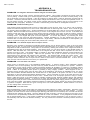
There are numerous Magnalock versions and numerous different applications exist for them.
Accordingly, this manual provides a broad range of information- only a portion of which is
applicable to any individual use. This manual guide provides a brief summary of many of the
Sections which allows you to consult only the portions of the manual that apply to your
application.
SECTION 1. DESCRIPTION--------------------------------------------------------------------- Page 1
SECTION 2. PHYSICAL INSTALLATION --------------------------------------------------- Page 1
This is the largest part of the manual with sections that explain the different types of
physical installations which vary according to door or gate types as well as Magnalock
versions.
SECTION 2.1 SURVEY --------------------------------------------------------------------------- Page 1
This section concerns how to pre-plan the installation.
SECTION 2.2 INSTALLATION TOOL KIT -------------------------------------------------- Page 1
This section explains an available accessory.
SECTION 2.3 GENERAL INSTALLATION ON OUTSWINGING DOOR ------------ Page 1
SECTION 2.3.1 STRIKE PLATE MOUNTING---------------------------------------------- Page 1
SECTION 2.3.2 MOUNTING THE MAGNET------------------------------------------------ Page 3
The above three sections explain the most common Magnalock installation on a door that
swings away from the lock. They also include general mounting instructions and should
therefore be read for all installations.
SECTION 2.4 GENERAL INSTALLATION ON INSWINGING DOOR --------------- Page 5
This section explains installation of "F" type Magnalocks on inswinging doors.
SECTION 2.5 MOUNTING PROCEDURES FOR SPECIFIC DOOR TYPES ------- Page 6
The following six sections provide specific advice depending on door type which includes
recommended bracketry.
SECTION 2.5.1 ALUMINUM FRAME GLASS DOOR MOUNTING------------------- Page 6
SECTION 2.5.2 THE UMB BRACKET FOR ALUMINUM AND CONCRETE ------ Page 7
SECTION 2.5.3 SOLID GLASS DOOR MOUNTING-------------------------------------- Page 8
SECTION 2.5.4 DOUBLE DOOR MOUNTING --------------------------------------------- Page 9
SECTION 2.5.5 CONCRETE HEADER OR WOOD FRAME MOUNTING ---------- Page 9
SECTION 2.6 MOUNTING THE MAGNALOCK ON EXTERIOR GATES----------- Page 10
This section, which includes three drawings, covers outdoor use of the Magnalock on a
variety of gate types.
SECTION 2.7 USE OF DRESS COVERS---------------------------------------------------- Page 12
This section introduces the Dress Cover which is used after physical mounting to improve
installation appearance and tamper resistance.
SECTION 2.8 TAMPER PROOFING THE MAGNALOCK ------------------------------ Page 12
This section should be read for any installation in a high vandalism area.
Ó Copyright, 2000, all rights reserved · Securitron Magnalock Corp., 550 Vista Blvd., Sparks NV 89434, USA
Tel: (775) 355-5625 · (800) MAGLOCK · Fax: (775) 355-5636 · Website: www.securitron.com
An ASSA ABLOY Group company
Rev. A.3, 5/00
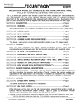
SECTION 3. ELECTRICAL INSTALLATION ----------------------------------------------- Page 13
SECTION 3.1 GENERAL ELECTRICAL CHARACTERISTICS ----------------------- Page 13
This section explains technically the Magnalock's electrical characteristics as a load and is
for reference.
SECTION 3.2 STANDARD LOCK ------------------------------------------------------------- Page 13
This section explains powering and switching the Magnalock.
SECTION 3.3 AVOIDING POOR RELEASE CHARACTERISTICS------------------- Page 13
This section warns against wiring mistakes specific only to the model 32 series.
SECTION 3.4 WIRE GAUGE SIZING--------------------------------------------------------- Page 14
This reference section explains how to select wire size for applications where the lock is
distant from the power supply.
SECTION 3.5 SENSTAT MAGNALOCKS: “SC”------------------------------------------ Page 14
Read this section if you have a Senstat Magnalock.
SECTION 3.6 DOUBLE DOOR PROCEDURE FOR STATUS REPORTING------- Page 15
This section applies if you have Senstat locks on a double door and want them to report as
a single lock.
SECTION 3.7 DOUBLE DOOR CONTROL SWITCHING-------------------------------- Page 15
This section applies whenever you have two locks controlled by a single switch.
SECTION 3.8 EMERGENCY RELEASE ----------------------------------------------------- Page 16
This section should be understood by all installers.
APPENDIX A TROUBLESHOOTING---------------------------------------------------------- Page i
Refer to this section before calling the factory on any operating problem.
APPENDIX B CALCULATING WIRE GAUGE SIZING----------------------------------- Page ii
This detailed reference section explains how to select wire gauge in complicated multi-lock
installations.
APPENDIX C CONSIDERATIONS FOR MAXIMUM PHYSICAL SECURITY ------ Page iii
This reference section explains the technical aspects of lock holding force and resistance to
attack. It contains numerous installation techniques which act to insure high lock security. It
must be read for high security applications and also has excellent educational value.
Rev. A.3, 5/00
Use of the Magnalock (or any lock) can lead to an unsafe
condition within the building if it is controlled in a manner that
improperly restricts passage through certain doors. The most
important area of concern is to insure that building evacuation is
not impeded in the event of a fire or other emergency condition.
Consult with the local building or fire department to insure that
the controls installed with the Magnalock create a safe and
code legal installation.
The Magnalock has an unlimited operating life and receives a
great deal of cumulative shock over this life from the door closing
and from persons attempting to open the door when it is
secured. It is therefore vital that it be firmly mounted to the door
header. If this is not done, a person's use of the door could
cause the magnet body to fall and possibly cause an injury. The
blind nuts furnished with the Magnalock will create strong and
permanent mounting when correctly collapsed inside the
header. If they are not collapsed, an unsafe condition will result.
Make sure you understand section 2.3.2 in the manual on
magnet mounting and collapsing the nuts.
SHOCK HAZARD. The Magnalock must
be operated from a DC power supply of appropriate capacity
and voltage. The DC output of the power supply must not be
connected to earth ground but must be isolated, or a shock
hazard and possible damage to the product could result. All
Securitron power supplies are delivered with isolated DC outputs
and the majority of commercial supplies are also furnished this
way. If you are not certain that the DC outputs of your power
supply are isolated, check with an Ohmmeter between earth
ground and +V, and then between earth and 0V (negative). You
should not have continuity.
-
Rev. A.3, 5/00
Page- 1
SECURITRON 32, 34, 62 AND 82 SERIES MAGNALOCK
INSTALLATION INSTRUCTIONS
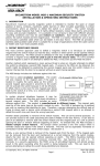
1. DESCRIPTION
Securitron’s Magnalock family represents the state of the art in electric locking. Three different
size models are available: The Model 32 and Model 34 series with a holding force of 600 lbs.
(275 Kg.); The Model 62 series with a holding force of 1,200 lbs. (550 Kg.) and the model 82
series with a holding force of 1,800 lbs. (820 Kg.). Several mounting and electronic options
are available which are described in this manual. Note that most points in this manual apply to
the entire Magnalock series. When a point applies to a particular Magnalock version, this will
be specifically noted.
2. PHYSICAL INSTALLATION
2.1 SURVEY
Because of the wide variety of situations in which the Magnalock may be utilized, first survey
the physical area in which it is to be installed and determine the best method of mounting it. In
this initial planning two considerations come into play: the mounting method must be strong
enough so that the full holding power of the Magnalock can be effective, and the Magnalock
and wiring must be protected to a reasonable degree from damage by intruders or vandals.
Often an accessory bracket is necessary, either furnished by Securitron or made up by the
installer. The brackets that can be used are covered later. Note that Magnalocks are supplied
with a complete set of fasteners. When shipped outside of North America, metric fasteners are
supplied and therefore the drawings in this manual show both US and metric fasteners.
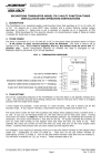
2.2 INSTALLATION TOOL KIT
Securitron offers an installation tool kit (part # IK or IKM, for metric use) which includes special
drills, a drilling template, a blind nut collapsing tool and extra fasteners and hardware. If the
installation is for a large number of locks or if the installer expects to perform other installations,
we recommend the purchase of this kit as it reduces installation labor and improves job quality.
2.3 GENERAL INSTALLATION ON OUTSWINGING DOOR
The Magnalock should be mounted under the door frame header in the corner farthest from the
hinges (see Figure 4). Most commonly, it is positioned horizontally but vertical positioning
should also be considered. In some cases for example, the horizontal header on an aluminum
frame glass door is not as strong as the vertical extrusion, so vertical mounting would be
preferred. This type of installation places the Magnalock such that the door swings away from
it. This configuration is necessary for all facility exit doors (otherwise, the Magnalock would be
on the outside of the building). For interior doors, the Magnalock should still be mounted in
this manner unless security planning anticipates a physical assault on the Magnalock from that
side of the door in which case see section 2.4 on inswinging door installation.
2.3.1 STRIKE PLATE MOUNTING
The strike should be mounted before the magnet on the upper corner of the door. The first
step is to locate the precise place you intend to mount the strike including deciding whether
you want to mount the Magnalock horizontally or vertically (see Section 2.3.2). The top of the
strike should be positioned about 1/10" (2.5mm) below the line where the door meets the
door stop, or below the header if there is no door stop to permit free closing. If the strike is
mounted vertically instead of horizontally, increase this stand-off distance to 2/10" (5mm).
More clearance is needed on a vertical mount because the strike projects out from the door and
can scrape the side frame as the door swings closed on its arc. Final positioning of the strike is
dictated by the desired position of the magnet. The strike must be centered on the magnetic
poles (3 bars) and the magnet is normally moved an inch or so in (or down) from the frame
corner so that the magnet mounting holes will not have to be drilled awkwardly in the corner.
When the strike position has been chosen, step two is to drill three holes in the door following
the template. Step three is mounting the white plastic bushings which surround and insulate
the roll pins into the 1/2" (12.7mm) holes. The bushings are employed to insulate the strike
electrically from a metal door and also help prevent the roll pins from wearing the door.
Rev. A.3, 5/00
Page- 2
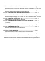
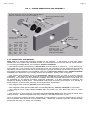
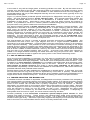
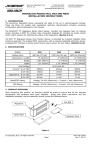
FIG. 1: STANDARD MAGNET DIMENSIONS AND ASSEMBLY
If "G" option is furnished, (62
and 82 series only), the wire
cable emerges from a 3/4"
male; 1/2" female conduit
fitting on the end of the
magnet. The mounting holes
are counterbored from both
sides to make the magnet
non-handed
32
(mm)
34
(mm)
62
(mm)
82
(mm)
Blind Nut
PN# BN-250 or
PN# BN-6MM (Metric)
(Pack of 40 with tool)
d
Mo
el
62
Gold Washer
PN# FW-1
(Pack of 24)
1/4-20 x 3" Cap Screw
PN# SCS-35 (Pack of 4)
6mm-1mm x 75mm
PN# 300-12650
d
Mo
Tamper Cap
PN# FC-1
(Pack of 24)
el
32
Length
8"
203
9.5"
241
8"
203
12"
305
Width
1.88
47.8
1.75
44.5
2.9
73.7
2.9
73.7
Depth
1.5
38.1
1.125
28.6
1.75
44.5
1.75
44.5
Recommended Tools:
1/2" or 3/8" Drill Motor
1/8", 3/8", 1/2" Drill Bits
1/2" Open or Crescent Wrench
3/16" Hex Key (Allen Wrench)
Hammer, Center Punch
Masking Tape, Fish Tape or
Leed Wire
Wire Strippers/Cutters
Crimp Wire Connectors
Multi-Meter
1/4-20 x 2 1/4" Cap Screw
PN# 300-12750 or
6mm-1mm x 55mm
PN# 300-12925
(For Model 32 Magnalock)
Step four is to insert the strike mounting hardware. Roll pins furnished with the strike should
be hammered into the strike. Be careful not to hit them too hard as it is possible to raise
dents on the strike surface by over driving the pins which degrades strike flatness and
therefore holding force. The strike is secured by the central strike mounting screw. Two
flexible washers are then placed between the strike and the door with the strike mounting
screw passing through the washers to provide flexibility. A third rubber washer is furnished.
This is not normally used but may be employed in case the spacing of the magnet and strike is
a little off. Adding the third washer will move the strike closer to the magnet. Do not place the
washers around the roll pins. The roll pins should "float" in their holes and not bind. Their
only purpose is to prevent the strike from rotating or spinning.
In step five, the strike is secured to the door via the supplied sex bolt. Note that we supply a
massive 1 1/4” diameter sex bolt as it is the only point of attack from the outside of the door. It
can be difficult to align the strike mounting screw with the sex bolt, so the following technique
is recommended: Start the sex bolt in its 1/2" (12.7 mm) hole but thread the strike mounting
screw into it (with strike plate and washers) before hammering the sex bolt down. Next,
hammer the sex bolt down and then screw the strike mounting screw in the rest of the way.
This makes alignment much easier.
Step six is to verify proper mounting. When the strike is mounted, make sure it flexes
freely around the washer stack. This flexing allows the Magnalock to pull the strike into
perfect alignment for maximum holding force. It is never possible for a door and frame to line
up well enough for the Magnalock to function unless the strike is allowed to flex.
Rev. A.3, 5/00
Page- 3
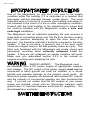
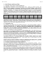
FIG. 2: STRIKE DIMENSIONS AND ASSEMBLY
Sex Bolt, Models 32, 62, 82, PN# SB-1, SB-1M (Metric)
Model 34, PN# 330-12100, 330-12150 (Metric)
Bushing (2), PN# 560-12050
R
PN u bb
# R er
W - Was
1(
Pa her (
ck 2)
of
24
)
Roll Pin (2), PN# 330-10800
1/4" x 1 1/4"
32
(mm)
34
(mm)
62
(mm)
82
(mm)
Length
6.25"
158.8
6.4"
164.5
6"
152.4
9.5"
240
Width
1.63
41.4
1.44
37
2.75
70
2.75
70
Depth
.5
12.7
.44
11.3
.5
12.7
.5
12.7
Bushing,
PN# 330-12000
Flathead Screw
5/16-18 x 1 3/4"
PN# 300-13600 or
8mm-1.25mm x 40mm
PN# 300-13750 (Metric)
2.3.2 MOUNTING THE MAGNET
Step one is to locate the mounting position of the magnet. It will mount in the door frame
header with four socket cap machine screws for metal frames or wood screws for wood frames.
In mounting the Magnalock, six conditions must be followed:
-- The frame header must present a flat surface for the magnet to mount to. 1 7/8” (48mm) for
the model 34, 2 1/4” (57mm) for the model 32 and 2 1/2" (63.5mm) for the model 62 and 82 are
required from the door to the rear of the magnet for proper mounting (as shown in Figure 4). If
this length of flat surface is not available, the use of stop filler plates and/or header brackets
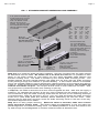
available from Securitron can usually resolve the problem. Again, refer to Figure 4.
-- The frame area selected must be structurally strong enough to yield a properly secure
installation. The issue of frame strength must be considered in selecting vertical or horizontal
mounting. One often finds on aluminum headers that the horizontal extrusion is weak and can
be snapped off, so vertical mounting would be preferred. It is also possible to reinforce the
header by adding a steel plate. The installer must avoid mounting the magnet to a wobbly or
weak support or the intrinsic security of the lock will be diminished.
-- The magnet face must be parallel to the strike plate.
-- The magnetic poles (three metal bars on the Magnalock), must be centered on the strike.
-- The magnet must make solid contact with the strike but still allow the door to close
properly.
-- The direction of door opening must pull the strike directly away from the magnet rather than
sliding it away. Electromagnets hold only weakly in the shear direction of pull.
Once a solid flat surface has been prepared for the magnet, it must be positioned so that its
face is parallel and centered to the strike plate. When the magnet has been experimentally
positioned this way, it's ready for mounting.
Rev. A.3, 5/00
Page- 4
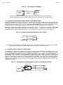
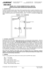
In step two, holes must be drilled for the mounting screws, and a 1/2" (12.7mm) diameter wireway hole should be drilled. Step three is to install the blind finishing nuts. For proper
strength, the 1/4-20 (or 6mm) mounting machine screws must be secured by these nuts. They
will work on any thickness metal header and are used as follows: A 3/8" (9.5 mm) hole is drilled
following the template for each nut. The nut is then pressed up into the hole and lightly seated
with a hammer tap. The nut is then collapsed inside the header. If you have Securitron's IK
installation kit, the nuts may be collapsed by the use of the blind nut placement tool. A special
collapsing tool is also included with each Magnalock. It is somewhat slower to use than the
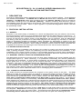
more elaborate tool found in the installation kit. For its use, see Figure 3.
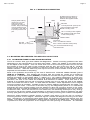
FIG. 3: COLLAPSING THE BLIND NUTS
COLLAPSES WHEN CAP SCREW
IS TURNED WITH ALLEN WRENCH
WHILE TOOL IS HELD FAST
WITH BOX WRENCH
DRILL 3/8" (9.5MM) HOLE
PRESS IN BLIND
NUT AS SHOWN
BLIND NUT
HEADER
HOLD WITH WRENCH OR
VISE GRIP WHILE TURNING
CAP SCREW
KNURL
TOOL
TWO FLAT WASHERS
CAP SCREW1/4-20 X 1" (US) OR
IF SCREW IS STIFF TO TURN,
6MM-1MM X 25MM (METRIC)
ADD LUBRICANT TO WASHERS
WHILE TURNING WITH ALLEN
WRENCH, PRESS IN TO KEEP
NUT SEATED IN HEADER
Step four is to make the necessary wire connections. Step five is to mount the magnet via the
supplied machine screws (see Figure 1). Don't forget to use the gold flat washers. They
prevent the narrow screw heads from digging into the resin which could cause damage.
Tighten the screws to a snug fit only. Use the supplied thread-lock on the screw threads to
avoid the possibility of the screws loosening over time. Do not drill out the mounting holes
to make for an easier fit. You may cut an internal wire and void the warranty.
FIG. 4: TYPICAL MOUNTING ON OUTSWINGING DOOR
Header Bracket if
frame is too narrow
Blind Nuts
Stop Filler Plate if
stop is too narrow
Stop
Washer Stack
1/4-20 (6mm)
Mounting Screws
Sex Bolt
Model 62 or 82 is shown
with four magnet mounting
screws. Model 32 or 34
employs only two.
Strike
Magnet Body
Tamper Caps
(One shown)
.75"
(19mm)
Door
2.5"
(63.5mm)
Rev. A.3, 5/00
Page- 5
2.4 GENERAL INSTALLATION ON INSWINGING DOOR WITH Z BRACKET
In cases where the Magnalock must be mounted on the inswinging side of the door to protect it
from physical assault, the magnet body is mounted flush on the wall above the door frame and
a "Z" bracket is affixed to the door which positions the strike in front of the Magnet (part # Z-32,
Z-62 or Z-82 with the suffix “M” for metric). The model 34 series is not offered in a face
mount version. Securitron's "F" series Magnalocks are used, as they have mounting holes
through the face of the magnet and wire exit to the rear. Figure 5 shows this configuration.
Note that the model 62F has five mounting holes through the face. The “extra” hole is to
provide flexibility in mounting when the magnet body is positioned partly on the top of the
door frame and partly on the wall. In that instance, it becomes possible to secure the model 62
magnet body with three screws which all go into the frame header (many wall types such as
sheet rock do not constitute a secure mounting substrate). Note that when the roll pin
bushings are used, they protrude through the Z bracket and interfere with the Z bracket cover.
If a Senstat lock is being employed, the roll pin bushings must be used to provide insulation.
They should be cut with a hacksaw to function in the bracket. If the lock is not Senstat, omit
use of the roll pin bushings and drill 3/8" (9.5mm) diameter holes for the roll pins instead of
1/2" (12.7mm). Read sections 2.3, 2.3.1, and 2.3.2 for additional general information on
mounting.
FIG. 5: F MAGNET DIMENSIONS
Blind Nut
PN# BN-250 or
PN# BN-6MM (Metric)
(Pack of 24 with tool)
If "G" option is furnished, the
wire cable emerges from a 3/4"
male; 1/2" female conduit fitting
on the end of the magnet (62
and 82 models only)
Model 62F
er
sh ( Pac
a
W -1
ld
Go # FW
PN
1/4-20 x 2 1/2" Cap Screw
PN# SCS-25 or
6mm-1mm x 60mm
PN# SCS-60mm (Metric)
Pack of four screws
f2
ko
4)
Model 32F
32
(mm)
62
(mm)
Tamper Cap
82
PN# FC-1 (Pack of 24) (mm)
Length
8"
203
8"
203
12"
305
Width
1.88
47.8
2.9
73.7
2.9
73.7
Depth
1.5
38.1
1.75
44.5
1.75
44.5
Rev. A.3, 5/00
Page- 6
FIG. 6: F MAGNALOCK MOUNTING
Roll pin plastic bushing
require 1/2" (12.7mm)
holes and must be
shortened to work in Z
bracket. Roll pin bushings
may be omitted if lock is
not Senstat. Then drill 3/
8" (9.5mm) holes for roll
pins.
Strike
Magnet
Architectural Cover slides on
last with open side up and is
attached with supplied double
stick tape
Z Bracket
T-Nut requires 3/8" (9.5mm) Dia
hole in bracket and accepts
strike mounting screw
Header
Use 1" mounting screw supplied
with Z bracket, PN# 300-13400
or 300-13450 (metric)
Washer Stack
Z Bracket
Cap Screw:
5/16" x 18, PN# 300-13500 or
8mm-1.25mm, PN# 300-13425 (metric)
Sex Bolt
Drill 1/2" (12.7mm) hole
#14 Hex Sheet Metal Screw (2)
PN# 300-13200
Door
2.5 MOUNTING PROCEDURES FOR SPECIFIC DOOR TYPES
2.5.1 ALUMINUM FRAME GLASS DOOR MOUNTING
This is a common door type that utilizes the Magnalock. Certain mounting problems can arise
depending on the configuration of the door and frame. Often, the header is not wide enough
for the depth of the magnet. This can mean that none of the mounting screws can be run into
the header or that in the case of the model 62 and 82, only two of the four will fit. Another
aspect of the mounting screw problem is that the screws might line up with the end of the
header extrusion. Also the wires may exit beyond the end of the header so that they will be
exposed and vulnerable to tampering.
Most of the problems are solved by the use of Securitron's Universal Header Bracket (part #
UHB-CL or UHB-BK). This bracket will function with the model 32, model 34 or model 62
Magnalock. A separate version (UHB-82) is offered for use with the longer model 82. The UHB
extends the depth of the header either 1" (25mm) or 1 1/2" (38mm) depending on which way
it's oriented. This usually allows mounting of all screws and since the bracket is itself a hollow
extrusion, the wire is run inside the bracket and therefore is hidden. Even with use of the
bracket, it is possible that one set of mounting screws may line up with the end of the header
when the model 62 or 82 is used. To deal with this situation, some adjustment of the magnet
mounting position is possible. Instead of the two rubber washers supplied with the strike, one
or three may be used. If the door is secured only by the Magnalock (there is no mechanical
swingbolt) the door closed position may be altered to allow all mounting screws to be used.
Finally note that a model 62 installation on this type of door is acceptable if only two mounting
screws are used. Since the screws run into steel nuts, the fastening technique is very strong.
It is best to use all four screws, but particularly on this type of door, which is inherently not high
security (the glass may be shattered for forced entry) firmly mounting two screws is acceptable.
Aluminum frame headers typically employ a “blade” stop which is far too thin to provide a
mounting surface for the magnet. Note that Figure 4 shows the Magnet mounting on the door
stop. Accordingly, on aluminum frame glass doors, the magnet body mounts directly onto the
header. This can be accomplished by cutting away a section of the blade stop. This technique
is preferred in that the projection of the magnet into the opening is minimized. An alternate
Rev. A.3, 5/00
Page- 7
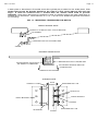
method is to space the magnet down so as to clear the blade stop. This generally requires 1/2”
of spacing (12.7mm) and Securitron offers brackets of the appropriate width with pre-drilled
clearance holes for the Magnet mounting screws. These are the ASB-32, ASB-62 or ASB-82
(with finish suffix CL or BK). Figure 6 shows the use of the Aluminum Shim Bracket (ASB).
Note that this bracket is not offered with the model 34. The UMB-34 bracket accomplishes the
same function.
FIG. 7: USE OF THE ASB BRACKET ON ALUMINUM DOOR/FRAME WITH BLADE STOP
HEADER
BLADE
STOP
ASB BRACKET
DOOR
STRIKE
MAGNET
ALUMINUM DOOR AND FRAME
WITH BLADE STOP
OCK
NA L H OLE S
G
A
2M
IV E
E L 3 HA S F
D
O
M
/8 2
FOR A SB -6 2
2
3
.
AS B OWN
H
IS S
SEX BOLT, STRIKE MOUNTING SCREW AND HOLE IN DOOR CAN ALL BE RAISED BY
1/4" WHEN OFFSET STRIKE IS USED WITH MODEL 62 TO SUIT NARROW RAIL
Another problem that can arise with aluminum frame glass doors is that in certain cases with
the model 62, the height of the aluminum rail at the top of the door is not sufficient to mount
the strike and sex bolt. Even when the sex bolt is installed in the lowest area of the top rail, the
top edge of the strike will protrude above the rail. To solve this problem, Securitron offers the
offset strike. The holes in the strike plate are offset 1/4" (6.4mm) from the center of the strike
and this allows successful mounting on a narrow top rail. An approximate 10% loss of holding
force results from the skewed position of the strike mounting screw but this is not significant on
aluminum frame glass doors which are not high security barriers. The offset strike is supplied
at no additional charge if it's called out with the order or may be sent as a replacement for the
standard strike. This problem does not occur with the more narrow model 32 or 34 so no offset
strike is offered with them.
2.5.2. THE UMB-BRACKET FOR ALUMINUM AND CONCRETE FILLED HEADERS
The UMB-34 bracket replaces the functions of the ASB bracket (see previous drawing) and the
CWB bracket (see Section 2.5.5) which permits mounting on wood or concrete filled steel
headers. The UMB has the unique benefit of being reversible which alters the projection of the
bracket with respect to the top of the magnet body and allows coping with different stop
thicknesses. The bracket is delivered with a selection of fasteners for different applications.
Wood screws are present for mounting on wood headers; cap screws are present for
installation into blind nuts and sheet metal screws are present for optional mounting on steel
headers.
Rev. A.3, 5/00
Page- 8
FIG. 8: USE OF THE UMB BRACKET WITH THE MODEL 34 MAGNALOCK
NOTE HOW BRACKET CAN BE REVERSED TO COPE WITH DIFFERENT STOP THICKNESSES
HEADER
BLADE
STOP
HEADER
STOP
UMB BRACKET
DOOR
UMB BRACKET
DOOR
ALUMINUM DOOR AND FRAME
WITH BLADE STOP
MAGNET
STRIKE
STRIKE
MAGNET
ALUMINUM DOOR AND FRAME
WITH BLADE STOP
THE TWO LARGER HOLES ARE FOR THE
CABLE EXIT. THE TWO THREADED HOLES
ACCEPT THE MAGNET MOUNTING SCREWS.
THE REMAINING FIVE HOLES ACCEPT
DIFFERENT FASTENER TYPES TO MOUNT
TO DIFFERENT HEADERS.
2.5.3 SOLID GLASS DOOR MOUNTING
The Magnalock is an excellent choice for securing 100% glass doors with no aluminum rail.
The magnet is suspended in normal fashion from the header and the difficulty in the
installation is mounting the strike plate on the glass door as glass cannot be drilled. This is
accomplished by using Securitron's model GDB (or GDBM with metric fasteners) Glass Door
Bracket and model AKG Adhesive Kit for Glass (see Figure 7). The GDB bracket will work with
either the model 32, model 62, or model 82 Magnalock (but not with the model 34). The
bracket is affixed to the glass surface by a special adhesive and the strike screws into the
bracket conventionally. The adhesive provides a permanent bond stronger than the holding
force of the Magnalock.
Note that we have said "100% glass door". Some doors that appear to be glass are actually
laminated with plastic. If the Magnalock with glass door bracket is used on this type of
door, it is possible that failure will occur via delamination.
In some cases the header of a glass door is vertical glass. The magnet can be mounted on
such a header by using a 3" X 3" aluminum angle bracket (part number HEB-3G). The bracket
is glued to the vertical glass header with Securitron's adhesive kit for glass and the magnet is
screwed to the bracket.
Rev. A.3, 5/00
Page- 9
FIG. 9: STRIKE INSTALLATION ON 100% GLASS DOOR
2 X RUBBER
WASHERS
SS
GLA
R
DOO
RB
DOO
S
S
GLA
5/16-18 x 1" (US) OR
8MM - 1.25MM X 25MM
(METRIC)
FLATHEAD SCREW
KET
RAC
IKE
STR
1/4" X 3/4"
ROLL PINS
WHITE PLASTIC
BUSHING
ADHESIVE
BOND
NOTE: OMIT ROLL PIN WHITE PLASTIC BUSHINGS
2.5.4 DOUBLE DOOR MOUNTING
Several possibilities exist for this application. In some cases, one of the door leaves is pinned
so that only one leaf is used and this is secured by a single Magnalock. If both leaves are to
be active, two Magnalocks can be used. For the most attractive installation, they should be
butted together but if obstructions exist in the header that interfere with mounting, the magnets
can be separated somewhat. Another possibility is to use Securitron's split strike which is
available for the model 62 and model 82 (use of a split strike with the model 32 or 34 series
would provide inadequate security) In this method, a single Magnalock is mounted in the
center of the header and a half size strike is mounted on each leaf. This reduces the holding
force to about 550 lbs. (250 KG) for each leaf with the model 62 and about 850 lbs. (385 KG)
for each leaf with the model 82. The split strike (part number ASS-62 or ASS-82 with “M” suffix
for metric) is available either as part of a complete Magnalock or supplied separately as a
replacement for the standard strike. Read section 2.7 for information on Dress Covers which
improve the appearance of a double door installation. Certain electronic considerations also
apply when Magnalocks are used on double doors. See section 3.5.4.
2.5.5 STEEL HEADER FILLED WITH CONCRETE OR WOOD FRAME MOUNTING
Securitron offers a combined bracket in three versions to suit the three Magnalock families.
The part number of the “Concrete/Wood Bracket” is CWB-32, CWB-62 or CWB-82. Two
finishes are available (suffix CL or BK) and for metric locks, the brackets include the suffix “M”.
Note that the CWB bracket is not offered with the model 34. It’s functions are accomplished by
the UMB bracket for the model 34.
In concrete filled headers, the blind nuts function normally but a problem can occur in pulling
the hook up wires as it is difficult to run a wireway in concrete. The center of the bracket for the
model 62 and model 82 versions forms a splice chamber if it's difficult to pull the wires back
into the header. The model 32 version has a slot to bring the wire into the header because of
the narrowness of the lock. Alternately the wires may be pulled through the edge of the
bracket by drilling a hole if it's impractical to drill the concrete. A final technique for concrete
headers is the use of Securitron's "G" version Magnalock (not available in the 32 or 34 series)
which incorporates a 1/2" female/-3/4" male universal threaded conduit fitting. The conduit
fitting is placed on the end of the magnet body, and the problem of pulling wires into concrete
is bypassed as the wires may be run in pipe in a surface mount configuration. The mounting
holes on "G" locks are counter-bored from both sides to make the lock non-handed.
With a wooden frame, long wood screws are used to mount the Magnalock. The screws must
penetrate as deeply as possible through the stop and frame into the header to yield adequate
mounting strength. The Magnalock mounts to the bracket via machine screws and the bracket
permits wood screws (furnished) to penetrate deeply into the header (see Figure 10)
Rev. A.3, 5/00
Page- 10
FIG. 10: WOOD FRAME AND CONCRETE HEADER BRACKET
CWB-32
S
A
E CH
P LI C
MB E
R
1/2"
MAGNET SCREWS INTO
2 OUTSIDE TAPPED HOLES
SHEET METAL
SCREWS USED
FOR CONCRETE
HEADER
WOOD SCREWS USED
FOR WOOD FRAME
USE ALL FURNISHED SCREWS FOR
PROPER MOUNTING SECURITY
CWB-62 AND CWB-82
S
A
E CH
C
I
L
P
MB E
R
1/2"
WOOD SCREWS USED
FOR WOOD FRAME
MAGNET SCREWS INTO
4 OUTSIDE TAPPED HOLES
SHEET METAL SCREWS
USED FOR CONCRETE
HEADER
2.6 MOUNTING THE MAGNALOCK ON EXTERIOR GATES
A popular application for the Magnalock is to secure motorized or manual exterior gates. The
Magnalock has several benefits in this application. Gates tend not to be precisely fitted so
electric bolts suffer from alignment failures. The Magnalock is designed to be self aligning and
tolerates considerable inconsistency in the gate closed position as regards upward/downward
alignment, side alignment and twisting. The Magnalock is also fully sealed and waterproof so it
is generally unaffected by tough environments.
The drawings and descriptions which follow, show conceptual installation concepts for different
types of gate security applications. Note that the model 62 and model 82 are most commonly
used in gate installations. They have conduit fittings available (“G” option) while this is not
available on the model 32 or 34 Most gate installations also call for higher levels of holding
force as gates are often large and poorly fitting. It’s also often the case that an intruder is able
to physically apply more force to defeat a gate lock than is the case with (especially) an
outswinging door wherein the intruder can only pull on it. The model 32 or 34 however may be
used on certain gates with success. A good example is a sliding gate where the Magnet can
be mortised into a post against which the gate slides. Securitron also offers the model 34R
Magnalock which is specifically designed for mortising (see catalog).
Because of the wide variety of gates in existence, each installation has to be considered special
and normally, bracketry must be made up on site. The concept is to mount the magnet on a
fixed post and the strike plate to the swinging or sliding member of the gate. Position both
components so that the strike plate slaps against the magnet face on closure. Usually, the
"GF" version of the Magnalock is used for gates. "G" calls out a conduit fitting mounted on the
magnet end and "F" calls out mounting holes through the face (see Figure 5). The magnet
typically screws onto a back plate fashioned on site and the back plate is welded onto the fixed
post.
Rev. A.3, 5/00
Page- 11
A back plate or Securitron's Z bracket must also typically be provided for the strike plate. The
strike plate cannot be directly welded to the gate as it will not be able to flex and self
align. It must be screwed onto a surface with the washer stack used to provide
flexibility. Note that if Securitron's Z bracket is used, it typically bolts to the gate rather than is
welded as it is aluminum. Read sections 2.3, 2.3.1, and 2.3.2 for additional general information
on mounting.
FIG. 11: MOUNTING TECHNIQUES FOR GATES
SINGLE SWING GATE
CONDUIT FITTING MAY EXIT TOP OR BOTTOM
GF MAGNET
Z BRACKET BOLTED TO SWING ARM
STRIKE
DOUBLE SWING GATE
Z BRACKET BOLTED TO SWING ARM
INTERFERENCE PIECE MUST
BE ADDED TO Z BRACKET
MOTORIZED OPENING MUST BE
COORDINATED
DIRECTION OF OPENING
SLIDING GATE
CONDUIT FITTING
GATE
EDGES
EXTENDED ROLL PIN
LOCK NUTS
ANGLE BRACKET
ANGLE BRACKET
SPRING
GF MAGNET
EXTENDED ROLL PIN
STRIKE
Rev. A.3, 5/00
Page- 12
In the case of very tall and large gates, a levering problem can exist. By this we mean that an
intruder may be able to flex the gate enough to take up the slack in the strike mounting screw
and then lever off the strike plate. If the installer or user determines that this may happen, a
single Magnalock will not provide adequate security and two must be used, typically at the top
and bottom of the gate.
Figure 11 (above) shows preferred special techniques for Magnalock mounting on 3 types of
gates. The first drawing shows a single swinging gate. The general technique follows the
principles discussed above but the use of Securitron's Z bracket which creates a neat
installation is also shown. Note that in some cases, the post which mounts the magnet is
hollow. It is possible to use the "F" version (without conduit fitting) and pull the wires through
the post which may yield a neater and more secure installation.
The second drawing shows a double swinging gate which presents a unique problem. The
Magnalock is mounted in the same general way as on a single swinging gate but since both
arms move, an intruder pushing on the gate exerts a shearing force on the Magnalock.
Electromagnets are not at all strong in this orientation of attack. Therefore, as the drawing
shows, Securitron's Z bracket should be used with an interference piece which blocks the
shearing effect while the strength of the magnet blocks one arm moving while the other is
stationary. For this technique to work, the motorized operator must be coordinated which
means that one arm must move first to clear the interference piece before the other arm starts
moving. Gate operators can normally accomplish this.
The final drawing on Figure 11 shows a special mounting technique for sliding gates. We
recommend the use of the "GF" type magnet and two 3" angle brackets (available from
Securitron) for a neat installation. A special strike mounting technique is shown in the drawing
which improves reliability. The problem is that if the strike is mounted normally to the angle
bracket and the gate is a powerful one which slams shut, the magnet may be impacted to the
point where its mounting screws loosen or the bracket bends. The strike mounting technique
that is shown creates a "shock absorber" effect by the use of lock nuts at the rear of the strike
and the rear of the bracket together with a spring. A through hole (rather than tapped) is
drilled in the angle bracket mounting the strike and extra long roll pins are used. When the
gate closes, the strike moves in against the spring which is the shock absorbing action.
2.7 USE OF DRESS COVERS
Once the physical installation is complete, you may want to consider the use of a dress cover.
Dress covers are metal stampings which slip over the magnet body and are affixed with
permanent double stick tape (supplied). The dress cover accomplishes three functions: First,
it makes for a more attractive installation by concealing the strike plate and mounting holes.
All that is seen is an attractive rectangular form on the door. Second, the cover provides an
extra degree of tamper proofing and finally it allows easy alteration of the finish for
architectural compatibility. Dress covers are available in clear aluminum, satin black aluminum,
polished stainless and polished brass finishes.
Double dress covers are also available for installations on double doors. In this case, the cover
fits over two locks so long as they are not separated by more than 2" (50mm). Double dress
covers have all the advantages mentioned above and in addition produce the appearance of a
single device which inside is really two. Consult the catalog for dress cover part numbers.
2.8 TAMPER PROOFING THE MAGNALOCK
In situations where vandalism is expected, the Magnalock should be protected from tampering.
The magnet itself is inherently tamper-proof being totally sealed. The magnet mounting screws
are vulnerable in that the magnet can be dismounted if the screws are loosened. The allen
holes on the screws can be filled with a potting compound, such as Devcon, or silicone.
Alternately, the entire hole in the magnet where the screw heads fit could be filled. Butyrate
caps are supplied to close the mounting holes. These provide some tamper proofing as they
can't be removed by hand, but can be pried out with a tool. Regarding the strike plate
mounting screw, it is covered by the strike when the magnet is energized. If tampering is
anticipated when the door is open, the screw socket head may be filled.
Another possibility is that Securitron inventories special tamper proof screws for both
magnet and strike mounting. These screws are identical allen head types except that it
requires a special key to install and remove the screws. It is unlikely that a vandal would have
access to this type of key. Securitron optionally supplies the tamper proof screw sets with keys
both in the form of a manual allen wrench and in a bit key usable with a drill.
Rev. A.3, 5/00
Page- 13
3. ELECTRICAL INSTALLATION
3.1 GENERAL ELECTRICAL CHARACTERISTICS
The Magnalock constitutes a low current electric load. Owing to internal circuitry, the
Magnalock does not show the normal characteristics of an electromagnetic or other inductive
load. Inductive kickback is suppressed, so arcing across switch contacts need not be a
concern. This suppression also protects nearby access control or computer equipment from
possible interference. The circuitry performs the additional functions of canceling residual
magnetism ("stickiness" on release) and accelerating field collapse so that the Magnalock
releases nearly instantly when power is removed. Electrically speaking, the load is nearly pure
resistive in nature although there is a modest capacitive component which depends on the
series. The following chart shows the current draw for each version and the degree of internal
capacitance.
32 @ 12V
32 @ 24V
34 @ 12V
34 @ 24V
62 @ 12V
62 @ 24V
82 @ 12V
82 @ 24V
CURRENT
300 mA
150 mA
350 mA
175 mA
250 mA
125 mA
350 mA
175 mA
CAPACITANCE
0
0
0
0
30 Mfd
15 Mfd
30 Mfd
15 Mfd
Capacitance can be an issue if very sensitive switch contacts are used to control the Magnalock
(such as a low current reed switch). A capacitive load includes some inrush current which can
stress these contacts. Note however that the problem is diminished when the Magnalock is
mounted some distance from the control switch as the interconnecting wiring adds a series
resistance to the circuit which sharply limits the inrush.
3.2 STANDARD LOCK
For operation, DC voltage must be provided to the lock. The red wire receives +12VDC or
+24VDC, and the black wire, 0V (negative). If the lock is connected with reverse polarity, it
will not function at all. The voltage source may be regulated, filtered or pulsating DC
(transformer + bridge rectifier). Half wave pulsating DC generated by a transformer and
single diode will not properly operate the Magnalock. An exact voltage level is not
necessary. Less than standard voltage will proportionately reduce holding force but will cause
no harm. Overvoltage up to 30% is acceptable.
The model 34, 62 and 82 series Magnalocks are dual voltage units. This means that you can
apply either 12 or 24 volts to the same unit and it will operate equally well. Dual voltage
Magnalocks are auto-switching which means that you still apply power to the red and black
wires, while observing correct polarity. The lock, however, automatically detects whether it is
receiving 12 or 24 volts and draws the correct amount of current for that voltage (the current is
twice as high when the lock is receiving 12 volts than when it is receiving 24 volts). The model
32 series has separate models for 12 and 24 volt operation.
It is good practice to use power supplies with 1/3 extra capacity beyond the current
requirements of the load. This greatly reduces the possibility of heat induced power supply
failure and also allows for future expansion. Power supply cost is a small fraction of the job
cost and should not be skimped on.
Switches may be wired as necessary between the Magnalock and power source. Internal
circuitry eliminates inductive kickback, so neither electromechanical switches nor solid state
devices will be damaged by arcing when the Magnalock is shut off.
3.3 AVOIDING POOR RELEASE CHARACTERISTICS
One of the exceptional features of Magnalocks is near instantaneous release. This is
particularly valuable when the lock is being switched off and the door is being opened at the
same time as occurs when a switched exit device like Securitron’s Touch Sense Bar is being
used. Two separate wiring errors can however cause Magnalocks to release slowly (in one or
two seconds) and this is annoying.
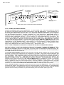
The first problem is connection of a reverse diode in parallel with the lock's power input.
This is often done to suppress inductive kickback from a coil such as a relay coil or solenoid.
Magnalocks already have internal inductive kickback protection, so addition of a reverse diode
is pointless. The diode does act to "recirculate" current flow through the magnet coil and
thereby considerably slows release. A diode should never be connected as shown in Figure
12.
Rev. A.3, 5/00
Page- 14
The second problem is when any load is operated in parallel with the Magnalock. A good
example would be adding an incandescent lamp in parallel with the lock so that the lamp
would be illuminated when the lock is powered. The lamp acts like a resistor and allows
current recirculation which will greatly slow lock release time. When you want to add a resistive
load in parallel with the lock, you must put a forward diode in series with the resistive load.
This will block recirculation and restore quick release. Correct practice is shown in Figure 12
below.
A special case exists when you use an LED connected in parallel with the Magnalock (to
show that the Magnalock is on for example). This does not slow release as the LED does not
allow recirculation but the limited recirculation energy will eventually burn out the LED. LED’s
are susceptible to even a tiny amount of reverse voltage. Therefore add the forward diode as
you would with an incandescent lamp (see Figure 12) to extend the life of the LED.
FIG. 12: WIRING CONSIDERATIONS TO AVOID SLOW RELEASE
RED
RED
MAGNALOCK
MAGNALOCK
BLACK
BLACK
NEVER CONNECT PARALLEL
REVERSE DIODE AS SHOWN
USE A FORWARD DIODE WITH ANY PARALLEL
RESISTIVE LOAD SUCH AS A LAMP
3.4 WIRE GAUGE SIZING
If the power supply is distant from the lock, voltage will be lost (dropped) in the connecting
wires so that the Magnalock will not receive full voltage. The following chart shows the
minimum wire gauge that will hold voltage drop to an acceptable 5% for different lock to
power supply distances. Proper use of the chart assumes a dedicated pair of wires to
power each Magnalock (no common negative). Note that a Magnalock operating on 24 volts is
a much better choice for long wire runs as it has 4 times the resistance of a 12 volt installation.
Also note that the correct calculation of wire sizing is a very important issue as the installer is
responsible to insure that adequate voltage is supplied to any load. In multiple device
installations, the calculation can become quite complex so refer to Appendix B for a more
complete discussion.
Distance
Gauge 12V
Gauge 24V
Distance
Gauge 12V
Gauge 24V
80 FT
20 GA
24 GA
800 FT
10 GA
16 GA
200 FT
17 GA
22 GA
1500 FT.
8 GA
14 GA
400 FT
14 GA
20 GA
3000 FT
N/A
12 GA
3.5 SENSTAT MAGNALOCKS: “SC”
Securitron's optional patented Senstat feature provides true lock status sensing. In many
electrically controlled door security systems, status sensing is provided by a magnetic switch
on the door itself. This indicates the door is closed but not necessarily secured. Securitron's
Senstat monitors the lock rather than the door and therefore provides higher security (but note
that it can’t be used as an auto-relock input to an access control system).
An “SC” Magnalock provides a dry SPDT output which changes state when the lock is reporting
secure (1 Amp @ 30 VDC maximum). This is accomplished by conducting the input power of
the lock through the strike and employing it to energize an internal SPDT relay. The white wire
is the Senstat relay common. Green is closed to white when the lock is secure and Orange is
closed to white when the lock is not secure.
Rev. A.3, 5/00
Page- 15
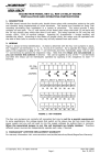
FIG. 13: “SC” SENSTAT WIRING
BLK
POWER
SUPPLY
ORANGE
GREEN
"SC" LOCK
RED
WHITE
+
WHITE AND GREEN WIRES PROVIDE ISOLATED CLOSURE WHEN LOCK IS SECURE.
ORANGE AND WHITE ARE CLOSED WHEN LOCK IS NOT SECURE (AS SHOWN ABOVE).
3.6 DOUBLE DOOR PROCEDURE FOR STATUS REPORTING
Often two Magnalocks are mounted on a double door and are turned on and off together (no
separate control). As to status reporting, it is of course possible to receive a separate Senstat
status signal from each door or you can combine the outputs so that if both locks are secure,
the double door is secure and if either lock is not secure, the double door is not secure.
Simply tie the two white wires together from the two locks. A circuit will be closed between the
two green wires only when both locks are reporting secure. If either is not secure, the circuit
between the two green wires will be open. The orange wires are not used. See Figure 14.
FIG. 14: DOUBLE DOOR WIRING WITH "SC" LOCKS
GREEN "SC" LOCK WHITE
GREEN "SC" LOCK WHITE
"SC" LOCKS ARE INTERWIRED AS SHOWN TO PROVIDE STATUS MONITORING. AN ISOLATED CLOSURE
WILL EXIST BETWEEN THE GREEN WIRES ONLY IF BOTH LOCKS ARE SECURE.
3.7 DOUBLE DOOR CONTROL SWITCHING
It’s common to control two locks from a single access and/or exit switch on double doors or on
an installation where two locks are mounted on a single door. In nearly all cases, this works
with no problem but occasionally the release can appear to be “sticky” for similar reasons to
those discussed in Section 3.3 This happens when one of the locks is poorly coupled to its
strike plate. This could occur because of an installation problem (the strike plate is not being
allowed to swivel) or because of some obstruction between the plate and magnet surface.
When an electromagnet is not well coupled to its strike plate, its magnetic field collapses so
rapidly that it provides some energy to recirculate in the second magnetic lock, slowing the
release of that lock.
FIG. 14: DOUBLE POLE SWITCHING OF TWO LOCK INSTALLATION
TWO POLE
SWITCH
+
POWER
SUPPLY
RED MAGNALOCK #1 BLK
RED
MAGNALOCK #2
BLK
Rev. A.3, 5/00
Page- 16
So if you notice slow release on a double lock installation, this is telling you that one of the
locks is not holding properly and that the problem should be corrected. Alternately, any
chance of slow release can be eliminated by controlling the two locks with a double pole switch
or relay. This blocks the recirculation path and is shown in Figure 15.
3.8 EMERGENCY RELEASE
Magnalocks are often wired into a system such that they can be released in an emergency -either manually from one switch or automatically, often from the fire alarm system. It is the
user's responsibility to accomplish this hookup correctly according to these instructions and
good electrical practices. In general, we recommend that a switch or relay be used to perform
a series break of all DC power which is the simple and sure way to make sure the doors do
release. Securitron power supplies have terminals for interconnection of such emergency
release switches. Finally please note that it is the responsibility of the end user and
dealer/installer to insure that Magnalock installations comply with any applicable fire or
building codes.
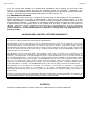
MAGNACARE LIMITED LIFETIME WARRANTY
SECURITRON MAGNALOCK CORPORATION warrants that it will replace at customer’s request, at any time for
any reason, products manufactured and branded by SECURITRON.
SECURITRON will use its best efforts to ship a replacement product by next day air freight at no cost to the
customer within 24 hours of SECURITRON’s receipt of the product from customer. If the customer has an account
with SECURITRON or a valid credit card, the customer may order an advance replacement product, whereby
SECURITRON will charge the customer’s account for the price of the product plus next day air freight, and will credit
back to the customer the full amount of the charge, including outbound freight, upon SECURITRON’s receipt of the
original product from the customer.
SECURITRON’s sole and exclusive liability, and customer’s sole remedy, is limited to the replacement of the
SECURITRON product when delivered to SECURITRON’s facility (freight and insurance charges prepaid by
customer). The replacement, at SECURITRON’s sole option, may be the identical item or a newer unit which serves
as a functional replacement. In the event that the product type has become obsolete in SECURITRON’s product
line, this MAGNACARE warranty will not apply. This MAGNACARE warranty also does not apply to custom, built to
order, or non-catalog items, items made by others (such as batteries), returns for payment, distributor stock
reductions, returns seeking replacement with anything other than the identical product, or products installed outside
of the United States or Canada. This MAGNACARE warranty also does not apply to removal or installation costs.
SECURITRON will not be liable to the purchaser, the customer or anyone else for incidental or consequential
damages arising from any defect in, or malfunction of, its products. SECURITRON does not assume any
responsibility for damage or injury to person or property due to improper care, storage, handling, abuse, misuse, or
an act of God.
EXCEPT AS STATED ABOVE, SECURITRON MAKES NO WARRANTIES, EITHER EXPRESS OR IMPLIED, AS
TO ANY MATTER WHATSOEVER, INCLUDING WITHOUT LIMITATION THE CONDITION OF ITS PRODUCTS,
THEIR MERCHANTABILITY OR FITNESS FOR ANY PARTICULAR PURPOSE.
PATENTS
Securitron’s Magnalock is covered under U.S. patents #4,516,114 and 4,682,801.
Rev. A.3, 5/00
Page- i
APPENDIX A
TROUBLESHOOTING
PROBLEM -- No magnetic attraction between magnet and strike plate.
First be sure the lock is being correctly powered with DC voltage. This includes connecting the power wires with
correct polarity. Positive must go to red and negative to black. If the Magnalock is wired in reverse polarity, it will
not be damaged, but it will not operate. If the unit continues to appear dead, it must be electrically checked with an
Ammeter. It must be powered with the correct input voltage and checked to see if it draws the specified current. If
the unit meters correctly, it is putting out the correct magnetic field and the problem must lie in the mounting of the
strike (see next paragraph). Section 3.1 includes a chart showing current draw for all Magnalock versions.
PROBLEM -- Reduced holding force.
This problem usually expresses itself in terms of being able to kick the door open or to open it with a shoulder.
Check the strike and magnet face to see if some small obstruction is interfering with a flat fit. Even a small air gap
can greatly reduce the holding force. Another possibility is if the strike plate has a dent on it from being dropped for
example. Remove the strike from the door and try to rock it on the magnet face to insure it is flat. If the strike and
magnet are flat and clean, the cause is nearly always improper mounting of the strike in that the strike is mounted
too rigidly. The strike must be allowed to float around the rubber washer stack which must be on the strike center
mounting screw. The magnet then pulls it into flat alignment. To correct the problem, try loosening the strike
mounting screw to see if the lock then holds properly. Another possibility is if you are operating the lock on AC
instead of DC or on half wave rectified DC (transformer + single diode). Half wave rectified DC is unacceptable; you
must, at a minimum employ full wave rectified DC (transformer + bridge).
PROBLEM -- The Senstat output does not report secure.
Because of the simplicity of Securitron's patented Senstat design, this is almost always a case of the lock status
sensor doing its job. It is not reporting secure because a small obstruction or too stiffly mounted strike is causing the
Magnalock to hold at reduced force. The problem is corrected by cleaning the surfaces of the magnet and strike or
establishing proper play in the strike mounting. If this doesn't work, you can verify function of the Senstat feature as
follows. Note that there are 2 thin vertical lines on the magnet face that can be said to separate the core into 3
sections from left to right. The Senstat output is created by the strike establishing electrical contact between the
leftmost and rightmost core segments. With the lock powered, use a pair of scissors and press the points
respectively into the leftmost and rightmost core segments. The Senstat output should then report secure. This
shows that the problem lies in the strike not making correct flat contact with the magnet face. If the scissors
technique doesn't cause the lock to report secure, check to see if there is a broken Senstat wire. If this is not the
case, the lock must be returned to the factory for replacement.
PROBLEM -- The lock does not release.
When power is removed from it, the Magnalock must release. If internal circuitry, which eliminates residual
magnetism, were to fail completely, the lock would only exhibit "stickiness" at a rough level of 5 pounds. Therefore
the complaint of "lock will not release" is either mechanical bonding via vandalism or a failure to completely release
power. By mechanical bonding, we simply mean that glue has been applied between the strike and magnet as a
prank. Failure to completely release power is generally a wiring integrity problem. What happens is that an
upstream switch removes power from the wires going to the Magnalock, but through an installation error, the wires
have their insulation abraded between the switch and lock so that partial or full power can leak in from another
Magnalock or other DC device with similarly abraded wiring. This is most likely to occur at the point where the wire
cable leaves the lock case and enters the door frame. Another area is via an improper splice on wiring in conduit.
Either a metal door frame or the metal conduit is capable of leaking power between multiple devices with abraded
wires, thereby bypassing switches. A good way to check this electrically (as opposed to visually removing and
inspecting the wires) is to use a meter and check for leakage between the power supply positive or negative and the
door frame and conduit. Magnalocks should be powered by isolated DC voltage without any earth ground reference
to positive or negative. Note that two types of wiring errors can cause slow release. Review Section 3.3 to see if
you are making either of these errors.
PROBLEM -- The lock rusts
Both the Magnalock core and strike plate are plated and sealed following a military specification. Because of this
plating and the sealed nature of the magnet, the Magnalock is weatherproof and may be used outdoors. If rusting
appears, the most common cause is that improper cleaning (with steel wool for instance) has occurred and this has
stripped off the relatively soft plating. Once the plating has been removed, it cannot be restored in the field, so the
lock will have to be periodically cleaned and coated with oil or other rust inhibitor. A rusty Magnalock will still function
but at reduced holding force. If the product is installed in a heavily corrosive atmosphere, such as near the ocean, it
will eventually rust even with non abrasive cleaning. The only answer then becomes continued periodic removal of
the rust.
Rev. A.3, 5/00
Page- ii
PROBLEM -- Apparent electronic noise interference with the access control system.
Electric locks, being inductive devices, return voltage spikes on their power wires and also emit microwave radiation
when switched. This can interfere with access control electronics causing malfunctions. Access control contractors
often employ installation techniques designed to isolate the access control electronics from the electric lock. These
include separate circuits for the lock, shielded wiring and other techniques. These techniques will vary with the
sensitivity of the access control system electronics and should, of course, be followed. Note that Magnalocks
include internal electronics which suppress both inductive kickback and radiation. They have been extensively tested
and accepted by numerous access control manufacturers and have been used in thousands of installations without
incident. An apparent noise problem is therefore usually not caused by the Magnalock. The access control
equipment may be itself faulty or have been installed improperly. One problem can arise with the Magnalock. If the
Senstat version is being used, the strike plate (which passes current) must be isolated from a metal door and frame.
Securitron supplies insulating hardware to accomplish this but the hardware might not have been used or the strike
may be scraping against the header for instance. Check for full isolation between the strike and the door frame
(when the door is secure) with an Ohmmeter. The presence of lock voltage potential in the door frame can interfere
with the ground reference of access control system data communication and therefore cause a problem.
IF YOUR PROBLEM PERSISTS
CALL SECURITRON TOLL FREE
1-800-MAG-LOCK
APPENDIX B
CALCULATING WIRE GAUGE SIZING
The general practice of wire sizing in a DC circuit is to avoid causing voltage drops in connecting wires which reduce
the voltage available to operate the device. As Magnalocks are very low power devices, they can be operated long
distances from their power source. For any job that includes long wire runs, the installer must be able to
calculate the correct gauge of wire to avoid excessive voltage drops.
This is done by adding the resistance of the Magnalock to the resistance in the power wires and then dividing the
wire resistance by the total resistance. This yields the fraction of voltage drop in the wires. For example, a single
model 62 Magnalock has a resistance of 192 ohms when being operated on 24 volts. If the wires completing the
circuit between the Magnalock and its power source have a resistance of 10 ohms, the total resistance is 202 Ohms.
Dividing 10 Ohms (the wire resistance) by 202 (the total resistance) yields roughly 1/20 or 5%. If the input voltage is
24 volts, 5% of this voltage will be dropped in the wires (1.2 volts) leaving 22.8 volts to operate the Magnalock. This
will cause a small reduction in holding force but in general, will be acceptable.
To calculate the wire resistance, you need to know the distance from the power supply to the Magnalock and the
gauge (thickness) of the wire. The following chart shows wire resistance per 1000 ft (305 meters):
Wire Gauge
Resistance/1,000 ft
Wire Gauge
Resistance/1,000 ft
8 Gauge
10 Gauge
12 Gauge
14 Gauge
.6 Ohms
1.0 Ohms
1.6 Ohms
2.5 Ohms
16 Gauge
18 Gauge
20 Gauge
22 Gauge
4.1 Ohms
6.4 Ohms
10.1 Ohms
16.0 Ohms
Model 32 resistances are 160 Ohms for the 24 VDC version and 40 Ohms for the 12 VDC version.
Model 34 resistances are 136 Ohms for 24 VDC operation and 34 Ohms for 12 VDC operation.
Model 62 resistances are 192 Ohms for 24 VDC operation and 48 Ohms for 12 VDC operation.
Model 82 resistances are 136 Ohms for 24 VDC operation and 34 Ohms for 12 VDC operation.
Let's look at some other sample calculations. Suppose a single 62 Magnalock operating on 24 volts is 1200 ft from
its power supply and we're using 20 gauge wire. First, the total length of the power wires is 2400 ft. Remember
that you combine the wire lengths from the power supply to the lock and back to the power supply to get
the total circuit wire length. The wire resistance than becomes 2.4 X 10.1 Ohms which is 24.2 Ohms. Adding this
to the Model 62 Magnalock resistance of 192 Ohms (at 24 volts) yields a total resistance of 216.2 Ohms. 24.2
divided by 216.2 yields the percent drop in the wires which is over 11% which we would consider excessive. The
problem can be dealt with in 2 ways. You can utilize 16 gauge wire which would reduce the drop to a more
acceptable 5% range or you can provide extra voltage at the power supply. For instance, Securitron 24 V power
supplies are adjustable from 24 to 28 volts. You can therefore easily set the power supply to output 11%
overvoltage which will then deliver 24 volts at the lock. The Magnalock will accept up to 30% overvoltage without ill
effects.
Rev. A.3, 5/00
Page- iii
Note that a Magnalock operating on 12 volts has 1/4th the resistance of a unit operating on 24 VDC. This means
that wire voltage drops are 4 times more significant in a 12 volt system than in a 24 volt system. In any job that
has wire runs long enough to be of concern, always use 24 volts. Note also that it's common to mount 2
Magnalocks on a double door and operate them as one lock (only 2 power wires). In this case, the resistance of the
pair of locks is half the resistance of a single lock.
In multiple lock jobs with a single power supply, the calculation of wiring voltage drops is more difficult. So long as
you run a separate pair of power wires to each lock, the calculation is as simple as has been described above, but if
a common power wire is used in a loop structure, the locks powered by the single loop will have an increasingly low
combined resistance so that the loop wire resistance will become more significant to the point where the locks don't
receive enough voltage. To find the combined resistance of multiple locks powered by a common wire, divide the
resistance of one lock by the number of locks. For example, eight 62 Magnalocks operating on 24 volts would have
a combined resistance of 192 divided by 8 which is only 24 Ohms. Another method is to calculate the current in
Amps in the wire and divide that into the circuit voltage. Since each 62- Magnalock operating on 24 volts draws
1/8th of an Amp, eight would draw 1 Amp. Dividing this into the same 24 volt input voltage yields a 24 Ohm
combined resistance.
In general, you have to be cautious about using common wires for loads in long distance situations unless you're very
confident about your ability to calculate the correct configuration. Bear in mind, however, that anytime you're
uncertain about the voltage drop in wiring, you can meter the voltage at the lock while it's connected and you will
be able to see if it's receiving adequate voltage. If the lock is not connected when you make this measurement, the
result will be false as the circuit will not see any lock resistance to compare to the wire resistance. You will read the
full input voltage.
APPENDIX C
CONSIDERATIONS FOR MAXIMUM PHYSICAL SECURITY
Magnalocks carries rated holding forces of 600 lbs. (275 Kg.), 1200 lbs. (550 Kg.) and 1800 lbs. (815 Kg.) for
respectively the model 32/34, 62 and 82. The figures are derived by using a calibrated hydraulic press to separate
the magnet and strike. The installer and user, however, are logically most interested in how Magnalocks perform on
a door rather than on a laboratory instrument and there are several installation and application variables that affect
the security level attained while using the Magnalock.
First, to achieve the rated holding force, the magnet face and strike plate must be clean. Even a small amount of
contamination will materially reduce the holding force. If cleaning is necessary, avoid the use of a heavy
abrasive such as steel wool which can remove the plating on the magnet face and strike. A sponge or plastic
pad such as Scotchbrite must be used.
Another requirement for maximum holding is that the strike plate must be centered on the magnet face and must
cover the magnetic core (3 bars). As is said in other parts of these instructions, the strike plate must be allowed to
swivel around the washer stack placed on the center strike mounting screw (not on the roll pins). Assuming the
magnet and strike are clean and are mounted in good alignment, the Magnalock will deliver its rated degree of
holding force on the door and the question becomes how much security does that provide on different door types?
In furnishing the answer we have to consider both the door construction and the likely type of attack.
In the case of wooden doors (other than solid hardwoods), aluminum frame glass doors, and hollow aluminum doors,
the model 32 or 34 should be employed in a “traffic control” mode. This means that a determined assault on the
door can “pop” these models open. The model 62 or model 82 Magnalock is generally stronger than the door itself.
Users have logged periodic cases of an assault destroying the door but leaving the Magnalock intact and still holding
a piece of the door. This raises the question of whether it ever makes sense to install the model 82 Magnalock on
non-steel doors since the model 62 is stronger than the door. Justification for using the model 82 lies in margin for
error. The greater strength of the model 82 can compensate for a dirt build-up or improper installation and this may
be warranted for the protection of critical areas. Steel clad fire doors or solid steel door such as are sometimes
found in prisons, are generally stronger than the model 62 Magnalock so the use of the model 82 Magnalock can
provide extra security for critical applications on steel doors.
In looking at methods of attack, the first point that must be made is that it is far more effective to force the
attacker to pull the door open rather than to allow him to push it. This is controlled by whether the door swings
away from or in to the protected area with the former being preferred. If the attacker can be forced to pull the door,
it is much more difficult for him to generate the requisite amount of force to defeat any of the Magnalock versions.
A crowbar may be used to try to pry open the door. At first, this seems to be a major worry as a long crow bar can
develop high force through leverage. In fact, what generally occurs is that the door experiences material failure.
The crowbar tears (in the case of wood) or bends (in the case of metal) the door material without defeating the lock.
Another factor that underlines the superiority of the Magnalock as regards physical security is that many attackers
will not be familiar with it. Expecting a conventional lock which secures between the door and frame, the attacker
Rev. A.3, 5/00
Page- iv
will employ the crowbar in an attempt to spread the door edge from the frame to clear the securing latch rather than
to pry the door open against the strength of the Magnalock. Electric strikes, however well made, can be
comparatively easily defeated with a crowbar by the tactic of spreading the door and this is why they should be
considered low security devices. The general fact that the Magnalock mounts on the other side of the door from the
attacker is an important contributor to its strong resistance to assault.
If the door must open in to the protected area, the attacker will have an opportunity to charge the door, kick it, or hit
it with an object. This is a less secure configuration, but Magnalocks never the less resist violent attacks of this
type. It is naturally important to use the strongest model Magnalock for the best security in this situation but the
ability of an attacker to defeat a Magnalock secured door that swings into the protected area is highly dependent on
the door type and mounting location of the lock on the door. The key factor is that the door should be able to
give when it receives a blow, thereby absorbing the force of the blow, rather than transmitting that force to
the lock. In more technical terms, the momentum of an object striking the door will generate momentary force at
the lock as a direct function of the deceleration of the arriving object. If the object decelerates abruptly, because the
door is very stiff, it will generate a large force. Slow deceleration, as the door gives with the arriving object,
generates a relatively small force at the lock.
Once the above paragraph is understood, we can conclude that the best place to mount the Magnalock on an
inswinging door is at the top of the door/header. In fact this is best place to mount any lock on an inswinging door.
Most people prefer to mount at the middle of the door as it gives a feeling of security when one shakes the door
from the doorknob. This however is an illusion. If a strong kick is struck right at the lock, the power of the kick is
transmitted nearly directly to the lock and there is a good chance of defeating the lock or its mounting. If the lock is
at the top of the door, a kick at the door center, causes the door to flex which absorbs most of the force of the blow.
The concept of preferring a door that gives, also affects the issue of physical security on different door types. Oddly
enough the characteristics that make an inswinging door strong, can make it more difficult to lock if it is stiff. Steel
doors and most particularly solid steel doors such as may be found in prisons, transmit blows much more
effectively to the lock and as such may be defeated by repeated leg blows or by charging the door. If the end user
has such doors and has as well a security environment where determined attacks can be foreseen on the doors, it is
his responsibility to insure that the Magnalock's strength is adequate for the application. Selection of the model 82 is
strongly recommended with another technique being the use of multiple locks.
For critical applications on stiff doors which swing in to the protected area, Securitron offers a component that
counteracts the stiffness of the door. This is the energy absorbing sex bolt (model EASB). Larger in diameter
than the standard sex bolt, the EASB incorporates a powerful internal spring which flexes to absorb the force of a
blow and thereby substantially increases the security of the installation.
As a final matter, be aware that the fasteners and mounting technique are just as important to successful physical
security as the strength of the lock. The fasteners must also naturally be employed on a frame area of sufficient
solidity so that it will not come loose in an attack. The Magnalock has been carefully designed to install with supplied
fasteners that substantially exceed the lock strength. If the installer replaces the factory supplied fasteners for any
reason, the success of the installation is in question. Turning to the details of Securitron's fasteners, first note the
sex bolt. This is a key component as the head of the sex bolt is the only part of the entire lock assembly that is
accessible to an attacker. Securitron's sex bolt is both large (1 1/4" dia. head) and is manufactured from steel.
Small commercially available sex bolts exist fabricated from both aluminum and brass. The use of such a component
destroys the security of the installation as the bolt head can be sheared with a chisel by an intruder.
It is also vital to mount the magnet with the supplied machine screws into the steel blind nuts. An alternate technique
is to use sheet metal screws which some installers feel is easier. This is extremely ill advised as the magnet
receives a torquing force each time the door is closed which will work the sheet metal screws free in time. We have
determined that sheet metal screws can be considered acceptable, although not preferred, if the header is made of
steel. Indeed this is mandated when Securitron's concrete header bracket is used. On an aluminum header,
however, sheet metal screw mounting is dangerous as the steel screw threads will gradually tear through
the relatively soft aluminum.
To fully complete an installation that maximizes the effectiveness of the fasteners, Threadlock (supplied) should be
used to defend the threads against loosening over time and please refer to section 2.8 on tamper proofing for
applications where vandalism can be expected.