1
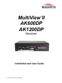
TM MultiView II AK600DP AK1200DP Receiver Installation and User Guide Document #5310267-01-01 (5/2/2013) © 1998-2013 by Magenta Research, LTD - All rights reserved. Magenta Research, LTD 128 Litchfield Road New Milford, Connecticut 06776 USA This document and the products to which it relates, and the copyright in each, is the property of Magenta Research, LTD. Neither the document nor the products may be reproduced by any means, in whole or in part, without the prior written permission of Magenta Research, LTD. Magenta Research, LTD, makes no warranty or representation, either express or implied, with respect to this software or documentation, including their quality, performance, merchantability, or fitness for a particular purpose. As a result, this software or documentation is licensed "as is" and you, the licensee, are assuming the entire risk as to their quality and performance. In no event will Magenta Research, LTD, be liable for direct, indirect, special, incidental, or consequential damages arising out of the use of or inability to use the hardware, software or documentation. Magenta Research, LTD, and the Magenta Research logo are trademarks of Magenta Research, LTD. All other brands, product names, and trademarks are the property of their respective owners. Magenta Research, LTD, reserves the right to change product functionality and/or specifications at any time without prior notification. MultiView™ II AK600DP/AK1200DP Installation and User Guide ii Precautions Precautions Safety Instructions ● English This symbol calls attention to important information. This symbol alerts the user of important maintenance (or servicing) and operating information. This symbol alerts the user to the presence of un-insulated dangerous voltages or other conditions in, or around, the product enclosure. These conditions can present a risk of electric shock or damage to equipment or facilities. Caution: Read Instructions: Read and understand all operating, installation, and safety instructions before using this equipment. Avoid Attachments: Only use accessories, attachments, tools, and materials that are recommended by the equipment manufacturer. Doing otherwise can compromise operating performance, create an unsafe condition, damage equipment, or violate the terms of usage or warranty. Follow Warnings: Always follow all instructions and warnings marked on the equipment or as detailed in related users’ guides. MultiView™ II AK600DP/AK1200DP Installation and User Guide iii Contact Information Contact Information For sales or technical support please contact your sales representative, or visit our website for updated contact information: www.magenta-research.com MultiView™ II AK600DP/AK1200DP Installation and User Guide iv Table of Contents Table of Contents Page Chapter 1 About this Manual ...................................................................................................................... 1 Chapter 2 Product Overview ....................................................................................................................... 2 2.1 Front Panel Interfaces ..................................................................................................... 2 2.2 Rear Panel Interfaces ..................................................................................................... 3 Chapter 3 Specifications ............................................................................................................................. 4 3.1 General Specifications .................................................................................................... 4 3.2 Category Cable Compatibility ......................................................................................... 5 Chapter 4 Installation .................................................................................................................................. 6 4.1 Option-Module Configuration .......................................................................................... 6 4.2 Prerequisites ................................................................................................................... 7 4.3 Installation Procedure ..................................................................................................... 7 4.4 Adjustments .................................................................................................................... 9 4.4.1 Cable Distance (EQ) Compensation Settings................................................. 9 4.4.2 Skew Compensation Settings ....................................................................... 10 4.5 Configuration Settings ................................................................................................... 11 4.5.1 Configuration Modes 1 & 2 ........................................................................... 11 4.5.2 Sync-mode Settings (LED1-2) ...................................................................... 12 4.5.3 4th Pair Settings (LED4-6) ............................................................................. 13 4.5.4 Vsync Polarity Settings (LED7)..................................................................... 14 4.5.5 Hsync Polarity Settings (LED8) .................................................................... 14 4.5.6 Clamp-mode Settings (CFG2: LED1-2) ........................................................ 15 4.5.7 4th Pair Termination Settings (CFG2: LED3) ................................................ 16 Chapter 5 Troubleshooting ....................................................................................................................... 17 Chapter 6 Connector Pinouts ................................................................................................................... 19 Appendix A (232) Option Module Settings .................................................................................................. 24 Appendix B Skew Module Installation ......................................................................................................... 26 Appendix C (SAP) Option Module Settings ................................................................................................. 27 Appendix D Pollable Serial Mode Address Chart ........................................................................................ 28 Appendix E Mounting Kits ........................................................................................................................... 30 Appendix F System Design Drawings ......................................................................................................... 32 Index 33 MultiView™ II AK600DP/AK1200DP Installation and User Guide v About this Manual Chapter 1 About this Manual This manual describes the Magenta MultiView™ II AK600DP and AK1200DP receivers, and contains the following information: Product overview (Chapter 2) Product specifications (Chapter 3) Installation and configuration instructions (Chapter 4) Troubleshooting (Chapter 5) Additional information (Appendices) The Magenta MultiView™ II family (MVII) of products introduces greater compatibility for handling HD video standards, as well as making nearly all user-configurable options “jumperless” via a digital front-panel userinterface. Note: MultiView-II products are fully backwards-compatible with previous MultiView products. Combining MVII with original MV products may limit access to some of the improved capabilities of the MVII series, so for best possible compatibility with sources and displays, always try to use MVII products throughout your system configuration. The following table shows the factory-configured versions of the MVII-AK600(1200)DP. Table 1: Available MVII-AK600(1200)DP Versions Version Description MVII-AK600(1200)DP-A Supports L+R summed audio (user-configuration setting). MVII-AK600(1200)DP-S Supports simplex serial (user-configuration setting). MVII-AK600(1200)DP-232 Supports 9-wire RS-232 serial (simplex or duplex TX/RX with hardware handshaking). Contains the (232) option module. MVII-AK600(1200)DP-SA Supports 3-wire RS-232 serial (simplex or duplex), and true stereo audio. Contains the (SA) option module. MVII-AK600(1200)DP-SAP Supports 3-wire RS-232 serial (simplex or duplex), and true stereo audio. The serial feature is POLLABLE, so that multiple receivers on a daisychained link can be addressed individually for display control or statusquery. Contains the (SAP) option module. Note: 1. 2. Each of the above variants is also available with the AkuComp-II skew-compensation module installed. The –A and –S versions are also field-configurable for S/PDIF digital audio extension on the 4th-pair. This equipment is not intended for, nor does it support, distribution through an Ethernet network. Do not connect these devices to any sort of networking or telecommunications equipment. Use only approved MultiView™ power adapters. Failure to do so may damage this device and will void the warranty. CHAPTER 3: SETUP & INSTALLATION MultiView™ II AK600DP/AK1200DP Installation and User Guide 1 Product Overview Chapter 2 Product Overview The MVII-AK600(1200)DP is a video receiver that is compatible with the entire MultiView™ family of products. It extends an analog video signal over standard CAT5 cable (also CAT5e and CAT6). There are userconfigurable settings for video, audio, and serial options which can be controlled from the front panel. The MVII-AK600(1200)DP features optional integrated skew compensation that can be varied in 2 ns increments to 65 ns total per color-channel to cancel the effects of skew in Category cables. This feature allows you to use CAT5e and reduced-skew CAT6 cables to lengths up to 600ft (186m) for AK600DP, or 1200ft (366m) for AK1200DP. All models support video refresh rates/resolutions of 1920x1200 to 600 feet (183m) with the AK600DP, and 1200ft (366m) with the AK1200DP. 2.1 Front Panel Interfaces The front panel of the MVII-AK600(1200)DP has the following controls and indicators: SKEW/SEL button Skew/EQ/Config adjustment buttons CFG/MODE button CFG indicator SKEW/SEL indicator EQ/SKEW range indicators Power-on indicator Figure 1: MVII-AK600(1200)DP Front Panel Interfaces There are four buttons (CFG/MODE, SKEW/SEL, DOWN, and UP) and several LED status indicators. All are used to display and control the operating modes of the receiver, with the LEDs having multiple functions. The CFG indicator shows these modes: In normal mode, the CFG indicator is off. In configuration mode, the CFG indicator will be on or flashing. MultiView™ II AK600DP/AK1200DP Installation and User Guide 2 Product Overview 2.2 Rear Panel Interfaces The rear panel of the MVII-AK600(1200)DP has the following ports: DB9 serial port (optional, on 232, SA and SAP models only) Video output to display UTP (link) input port Auxiliary signals UTP (link) output port DC power input port Figure 2: MVII-AK600(1200)DP Rear Panel Interfaces MultiView™ II AK600DP/AK1200DP Installation and User Guide 3 Specifications Chapter 3 Specifications This section describes the following specifications: 3.1 General specifications Category cable compatibility General Specifications The following table lists the general specifications of the MVII-AK600(1200)DP. Table 2: MVII-AK600(1200)DP General Specifications Item Description Cable Required Compliance Video Support Resolution & Refresh Rate Required source impedance Required destination impedance Audio Characteristics Serial Characteristics Connectors Temperature Tolerance Humidity Tolerance Enclosure Power Size Weight Category 5, 5e, or 6 cable. Shielded or unshielded twisted pair. Low-skew. CE; FCC Class A, IC Class A, UL listed I.T.E Device. All supported VESA modes to WUXGA (1920x1200), RGBHV, RGsB, RGBs, Composite (NTSC, PAL, SECAM), S-Video, Component Video, widescreen modes, HDTV modes including 1080p, 1080i, 720p MVII-AK600DP: At 600ft(183m) or less: a maximum of 1920x1200. MVII-AK1200DP: At 1200ft(183m) or less: a maximum of 1920x1200. Video OUT: 75 ohms Audio models: Audio OUT (if any): capable of driving 10K ohms load. SPDIF audio mode: 75 Ohm Video IN: 75 ohms Audio models: Audio IN (if any): 1K ohms minimum input impedance SPDIF audio mode: 75 Ohm (A) model: Right/Left summed, 50K input impedance, line level, unbalanced. (SA) and (SAP) models: Full stereo, 10K ohms input impedance, line level, unbalanced. (S) model: Protocol: Asynchronous; transparent to data format; transparent to data rates up to 115 kbps simplex. (232) model: Protocol: Asynchronous; transparent to data format; transparent to data rates up to 19.2 kbps full duplex; data rates to 115 kbps simplex and half-duplex. (SA) model: Protocol: Asynchronous; transparent to data format; transparent to data rates up to 9.6 kbps full duplex or simplex. (SAP) model: Protocol: Asynchronous; transparent to data format; transparent to data rates up to 19.2 kbps full duplex or simplex (9 fixed baud rates are supported). (1) 4 pin phoenix (2) RJ-45 (1) HD15 F (1) DB9M (only if one of the 232, SA or SAP option modules is installed) Operating: 32 to 104°F (0 to 40°C) Storage: -4 to +140°F (-20 to +60°C) Up to 80% non-condensing Steel, black powder-coat finish. Input voltage: +5 VDC @ 1.2 Amps max. Consumption: 6 watts maximum 1.2"H x 3.6"W x 5.5"D (3.0 x 9.2 x 14.0 cm) 1.0 lb. (0.45 kg) MultiView™ II AK600DP/AK1200DP Installation and User Guide 4 Specifications 3.2 Category Cable Compatibility MultiView products are compatible with Cat5/5e/6 data cabling, as well as “minimized skew” CAT5/5e cabling (also referred to as “low-skew”) manufactured specifically for video applications. Follow these tips to ensure proper usage of your Category cabling: Some “low-skew” CAT5 is specific to a particular vendor and is incompatible with our products. Ensure that any “low-skew” CAT5 cable is non-proprietary before purchase and installation. CAT6 cable, due to the manufacture method, can exhibit much greater skew than standard CAT5/5e and might require skew compensation beyond what the capabilities of the AkuComp-II option module offers. Please contact Magenta Research for assistance. CAT5/5e/6 cabling for the Magenta MultiView™ Series must be pinned to the TIA-EIA T568B wiring specification. We also highly recommend that all CAT5 cables be pre-terminated and tested. Cables terminated onsite or in an existing infrastructure should be tested before use to ensure compliance with the TIA-EIA T568B specification. Using incorrectly terminated CAT5 cables can damage the Magenta MultiView™ Series. The Cat5/5e/6 cable should be suitably rated Listed cable ( DUZX ) communication cables, TYPE CMP, CMR, CMG or CM as designated in the NEC. Cables are to be installed in accordance with the NEC and local building and electrical codes. This is the responsibility of the end user/installer of this product. The following figure shows the T568B Wiring specification. Figure 3: T568B CAT5 Specification MultiView™ II AK600DP/AK1200DP Installation and User Guide 5 Installation Chapter 4 Installation This section describes the following installation topics: Data mode configuration Prerequisites to installation Installation procedure Post-installation adjustments Post-installation configuration settings This equipment is not intended for, nor does it support, distribution through an Ethernet network. Do not connect these devices to any sort of networking or telecommunications equipment! Do not connect DC power until instructed to do so. 4.1 Option-Module Configuration If your MVII-AK600(1200)DP receiver is equipped with one of these option modules: (232), (SA) or (SAP), then the following information will be important to review BEFORE installing the receiver: The MVII-AK600(1200)DP-232 serial receivers are factory-configured for duplex-serial with full modem controls. The mode must be changed to simplex if you are using one of the following installations: Daisy chained receivers. Using a multi-output transmitter (T4). Using a MultiView distribution amp (MV-9D). Using a MultiView matrix switch (Mondo-III or MV-16x16). Please refer to Appendix-A for (232) module configuration information. The MVII-AK600(1200)DP-SA version offers RS232 duplex serial in addition to stereo audio. The serial interface is 3-wire (TX, RX, GND) and does not support full modem signals. The maximum serial baud rate is 9600. Simplex modes are supported without jumper or other changes by simply using the TX signal only. SAequipped receivers require no other special configuration. The MVII-AK600(1200)DP-SAP version offers pollable RS232 duplex serial in addition to stereo audio. The serial interface is 3-wire (TX, RX, GND) and does not support full modem signals. The factory-default serial baud rate is 9600 baud, but this is a user-configurable option using “SAP-II” serial commands. Simplex modes are supported without jumper or other changes by simply using the TX signal only. The SAP-module capability of polling and interacting with specific receivers requires that each receiver have a unique address setting. Please refer to Appendix-C for (SAP) module configuration information. MultiView™ II AK600DP/AK1200DP Installation and User Guide 6 Installation 4.2 Prerequisites Depending on the specific installation requirements, some common tools (screwdrivers, nut-drivers) and related hardware (mounting screws) might be required. These are not provided with Magenta products. The following items might be necessary, which are available from Magenta Research: Audio cable: Phoenix 4-pin to RCA. Video cable: HD15 connectors, or one of several BNC/RCA/S-Video breakout cables. Serial cable: Phoenix 4-pin to DB9, or one of several DB9-M/F, M/M or F/F extension cables. Note: You will need appropriate Category cable as previously described, to connect the MVII-AK600(1200)DP to other MultiView™ and MultiView™ II devices. Magenta does not supply Category cable. 4.3 Installation Procedure Ensure that all connectors are clean and free of contaminants prior to making the connections. Appropriate connector locking hardware (screws/latches) should be used to prevent cables from disconnecting or causing intermittent operation. All units must be the same type for 4th-pair supported features to function correctly. For example, an “XRTx-A” must be connected to a MVII-AK600(1200)DP-A, as both must be identical to work properly with L/R summed audio. Similarly, an “XRTx-SA” cannot be used with an MVII-AK600(1200)DP-A”. Video modes may function normally, but 4th pair options will not. To install a typical MultiView transmitter (these steps are generic - refer to the appropriate MultiView transmitter manual): 1. Connect the source video to the Magenta MultiView™ transmitter video input port, which is an HD15 connector labeled SOURCE IN or VIDEO IN. 2. If desired, attach a local monitor to the HD15 connector labeled LOCAL OUT (if available). 3. Make your audio or serial connections via the phoenix connector or DB9 connector as appropriate. 4. Connect the CAT5 cable to the transmitter. 5. Apply power to the transmitter. a. The power-on LED should light up. b. If there is a local monitor attached, a video image should appear on the monitor. MultiView™ II AK600DP/AK1200DP Installation and User Guide 7 Installation To install the MVII-AK600(1200)DP receiver: 1. Connect the VGA OUT connector to the display. 2. Connect any audio and/or serial cables to the (AUX I/O) and (IOIO) connectors, depending on the specific model of receiver you are installing. Please refer to the –A, -S, -232, -SA and –SAP option descriptions for more information. 3. Connect the Category cable from a MultiView transmitter to the LINK INPUT connector on the receiver. 4. If you are daisy-chaining multiple receivers, also connect the downstream Category cable to the LINK OUTPUT port on the receiver. 5. Connect the DC power cable to the POWER port, and check for the following indicators: The power-on LED should light up (Green). The CFG indicator is off. The SKEW/RGB indicator is off. The EQ/SKEW indicators display the current EQ settings (0 to 100%). 6. IMPORTANT: Adjust the receiver’s EQ and/or SKEW (optional) settings. 7. When the EQ setting is properly adjusted, the video should appear on the display (make sure display is powered ON). 8. Make any other required configuration changes via the LED/button user-interface. It is critical that the EQ setting be adjusted to compensate for the length of the Category cable leading back to the transmitter. Skew compensation adjustment (if your MVIIAK600(1200)DP is equipped with an AkuComp-II module) will also be important for best image quality. Connect the video out HD15 connector to the display device. Connect the CAT5 cable via the LINK INPUT port. (Optional) Make your serial and/or audio connections via the DB9 IOIO or AUX I/O connectors, as appropriate. Refer to –A, -S, -232, -SA and -SAP option descriptions. (Optional) Connect the output CAT5 cable via the LINK OUTPUT port. Connect the DC power cable (+5VDC @ 3A. max) to the POWER port. Figure 4: MVII-AK600(1200)DP Receiver Installation Procedure MultiView™ II AK600DP/AK1200DP Installation and User Guide 8 Installation 4.4 Adjustments This section describes how to make the following adjustments: 4.4.1 Cable distance (EQ) compensation Skew compensation Cable Distance (EQ) Compensation Settings When the MVII-AK600(1200)DP is operating in normal mode (CFG indicator is off), it is possible to quickly adjust the EQ. The EQ/SKEW indicators 1-8 will change accordingly to show (in “bargraph” form) 0 to 100% of the available EQ adjustment range (AK600DP = 0 to 600 ft, AK1200DP = 0 to 1200 ft). For best results, use the Magenta EQ/Skew test pattern image if possible. A test pattern image and video instructions is available at http://www.magenta-research.com/test. The following figure shows the test image you can use to make the EQ adjustment. Figure 5: EQ-adjustment test image To adjust EQ: 1. From normal-mode, press and hold the UP or DOWN button until the SKEW/RGB indicator turns on (VIOLET). Release the UP or DOWN button. 2. Press the UP or DOWN buttons repeatedly to adjust the EQ setting, either one step at a time or hold for auto-repeat. 3. To exit EQ-ADJUST mode, leave the buttons untouched for 10 seconds, or press the CFG button once. MultiView™ II AK600DP/AK1200DP Installation and User Guide 9 Installation 4.4.2 Skew Compensation Settings If the AkuComp-II skew module is installed, it is possible to quickly adjust the RGB values when the MVIIAK600(1200)DP is operating in normal mode. The EQ/SKEW indicators 1-8 will change accordingly to show (in “bargraph” form) 0 to 100% of the available SKEW adjustment range (0 to 65nSec). For best results, use the Magenta EQ/Skew test pattern image if possible. A test pattern image and video instructions is available at http://www.magenta-research.com/test. If skew compensation is required, but the skew module is not installed, call for technical assistance. Your product may need to have the skew-module added to it. The following figure shows the test image you can use to make the SKEW adjustment. Figure 6: Image Adjustment Utility Skew To adjust skew: 1. From normal mode, press and hold the SKEW/SEL button until the SKEW/RGB indicator turns on RED. Release the SKEW button. 2. Press the UP or DOWN button repeatedly to adjust the RED skew value. 3. Press and release the SKEW/SEL button. The SKEW/RGB indicator will turn GREEN. 4. Press the UP or DOWN button repeatedly to adjust the GREEN value. 5. Press and release the SKEW/SEL button. The SKEW/RGB indicator will turn BLUE. 6. Press the UP or DOWN button to adjust the BLUE value. 7. Pressing the SKEW/SEL button again will return you to step-2, allowing adjustment of the RED skew again. 8. To exit SKEW-ADJUST mode, leave the buttons untouched for 10 seconds or press the CFG button. MultiView™ II AK600DP/AK1200DP Installation and User Guide 10 Installation 4.5 Configuration Settings There are a number of configurable operating parameters, and the factory-default settings should work for most applications. However, some applications might require slight configuration changes. This section describes how to configure the following settings: Config-1 mode, LEDs 1-2: Config-1 mode, LEDs 4-6: Config-1 mode, LED 7: Config-1 mode, LED 8: Config-2 mode, LED 1-2: Config-2 mode, LED 3: Sync-mode settings 4th pair settings Vsync polarity settings Hsync polarity settings Clamp-mode settings 4th pair termination settings Nearly all settings are available from the front-panel buttons/LEDs. The enclosure does not need to be opened unless an option module is being installed or removed, or settings specific to the option module need to be changed. 4.5.1 Configuration Modes 1 & 2 For configuration settings, the receiver must be in Config-1 or Config-2 mode (CFG indicator is on or flashing). Once in a configuration mode, any changes are effective immediately and are saved in non-volatile memory. To enter configuration-mode-1: Press and hold the CFG button until the CFG indicator turns on. o Once in this mode, the LED indicators 1-8 will display the current settings for the Config-1 settings. To enter configuration-mode-2: Press and hold the CFG button until the CFG indicator turns on. Press the SEL button exactly 5 times. The CFG indicator will start flashing. o Once in this mode, the LED indicators 1-8 will display the current settings for the Config-2 settings. To exit configuration-mode: Leave the buttons untouched for 10 seconds. The CFG indicator will turn off (normal-mode). Or, press the CFG button once. You will immediately leave Config-1 or Config-2 mode. To quickly reset all user-configurable options back to factory-default settings: 1. Disconnect the DC power cable (or AC power). 2. Press and hold the CFG button. 3. Connect the DC power cable (or AC power). All LEDs blink 3 times, indicating all settings are now changed back to factory-defaults. 4. Release the CFG button. MultiView™ II AK600DP/AK1200DP Installation and User Guide 11 Installation 4.5.2 Sync-mode Settings (LED1-2) The receiver is factory-configured for auto-detecting the proper sync-mode (RepliSync-I normal/stretched). This mode is generally compatible with all existing MultiView transmitter and receiver products that support RepliSync (if they are also using their default settings). However, some video sources may require a custom sync-mode setting (especially at 1080p and 1920x1200 video resolutions). For these cases, one of the other sync-modes can be selected. Note that any connected MultiView device (transmitter or daisy-chained receiver) MIGHT also require a change to its sync-mode settings. Otherwise, you may not get a proper video display output at one or more receivers. Perform the following procedure while the receiver is in the normal operating state (CFG indicator is off): 1. Press and hold the CFG button until the CFG indictor is ON. Release the CFG button. a. LEDs 1-8 will show the current value for all Mode-1 configuration settings as bright (same as ON), dim (same as OFF). 2. Press and release the SKEW/SEL button once. 3. LED indicators 1 and 2 should be illuminated (either ON or DIM); all others (indicators 3-8) should be off. 4. Press the UP and DOWN buttons to step through the available sync-mode settings as shown below. 5. To leave configuration-mode, leave the buttons untouched for 10 seconds or press the CFG button. Table 3: Sync-Mode Settings LED1 LED2 Front Panel View Sync-mode Setting dim dim The receiver will auto-detect the required RepliSync-I mode (“normal” or “stretched”). This is the factorydefault setting. dim ON Force RepliSync-II mode. This is compatible with MultiView II “RepliSync-II” mode only (when connected to a MultiViewII transmitter). ON dim Force fixed-sync mode. NOTE: The source MultiView transmitter must also be in fixed-sync mode. Note that H/V polarity settings must also be selected at each receiver. MultiView™ II AK600DP/AK1200DP Installation and User Guide 12 Installation 4.5.3 4th Pair Settings (LED4-6) The receiver provides several options for using the 4th-pair signals (pairs 1-3 are generally used for video). The factory-default setting (-A) supports summed L+R analog audio on the 4th-pair. Note that the connected MultiView transmitter and any daisy-chained receivers must be configured with a matching 4th-pair operating mode. Otherwise, the desired 4th-pair signal will not work as expected (but the video will not be affected). Perform the following procedure while the receiver is in the normal operating state (CFG indicator is off): 1. Press and hold the CFG button until the CFG indictor is ON. Release the CFG button. a. LEDs 1-8 will show the current value for all Mode-1 configuration settings as bright/off. 2. Press and release the SKEW/SEL button twice. 3. LED indicators 4-6 should be illuminated (either DIM or ON); all others (indicators 1-3, 7 and 8) should be off. 4. Press the UP and DOWN buttons to step through the available 4th-pair settings as shown below. 5. To leave configuration-mode, leave the buttons untouched for 10 seconds or press the CFG button. Table 4: 4th-Pair Settings LED4 LED5 LED6 Front Panel View (THP: Need new photo.) 4th-pair Operating Mode If option-module is installed: 4th-pair operating mode is defined by the presence of the option-module (232/SA/SAP) and this setting cannot be changed. If the option-module is not installed: 4th-pair signals are disabled. This effectively “mutes” anything being sent on the 4th pair. This can be useful for diagnostic purposes. dim dim dim dim dim ON Direct pass-through of 4th-pair wires (custom applications). dim ON dim External analog (L+R summed) audio (“-A” mode). This is the factory-default mode if no daughterboard option is installed. (Remember to also check 4th-pair termination setting) dim ON ON External S/PDIF digital audio. Output-impedance = 75ohms. (Remember to also check 4th-pair termination setting) ON dim dim Simplex-serial (“-S” mode) (Remember to also check 4th-pair termination setting) MultiView™ II AK600DP/AK1200DP Installation and User Guide 13 Installation 4.5.4 Vsync Polarity Settings (LED7) The receiver provides settings for Vsync polarity: (+) or (-). The factory default setting is (+) Vsync polarity, or “ON” for configuration LED 7. Perform the following procedure while the receiver is in the normal operating state (CFG indicator is off): 1. Press and hold the CFG button until the CFG indictor is ON. Release the CFG button. a. LEDs 1-8 will show the current value for all Mode-1 configuration settings as bright/off. 2. Press and release the SKEW/SEL button three times. 3. LED indicator 7 should be illuminated (either DIM or ON); all others (indicators 1-6 and 8) should be off. 4. Press the UP and DOWN buttons to change Vsync polarity from Positive (bright) to Negative (dim). 5. To leave configuration-mode, leave the buttons untouched for 10 seconds or press the CFG button. Note: This setting only has an effect if the sync-mode is set to “Fixed”. 4.5.5 Hsync Polarity Settings (LED8) The receiver provides settings for Hsync polarity: (+) or (-). The factory default setting is (+) Hsync polarity, or “ON” for configuration LED 8. Perform the following procedure while the receiver is in the normal operating state (CFG indicator is off): 1. Press and hold the CFG button until the CFG indictor is ON. Release the CFG button. a. LEDs 1-8 will show the current value for all Mode-1 configuration settings as bright/off. 2. Press and release the SKEW/SEL button four times. 3. LED indicator 8 should be illuminated (either DIM or ON); all others (indicators 1-7) should be off. 4. Press the UP and DOWN buttons to change Hsync polarity from Positive (bright) to Negative (dim). 5. To leave configuration-mode, leave the buttons untouched for 10 seconds or press the CFG button. Note: This setting only has an effect if the sync-mode is set to “Fixed”. MultiView™ II AK600DP/AK1200DP Installation and User Guide 14 Installation 4.5.6 Clamp-mode Settings (CFG2: LED1-2) The receiver allows you to select the video clamp-mode. Perform the following procedure while the receiver is in the normal operating state (CFG indicator is off): 1. Press and hold the CFG button until the CFG indictor is ON. Release the CFG button. a. LEDs 1-8 will show the current value for all Mode-1 configuration settings as bright/off. 2. Press and release the SKEW/SEL button exactly five times. a. The CFG indicator will start flashing. b. LEDs 1-8 will show the current value for all Mode-2 configuration settings as bright/off. 3. Press and release the SKEW/SEL button once. 4. LED indicators 1 and 2 should be illuminated (either DIM or ON); all others (indicators 3-8) should be off. 5. Use the UP and DOWN button repeatedly to step through the available video-option settings as shown below. 6. To leave configuration-mode-2, leave the buttons untouched for 10 seconds or press the CFG button. Table 5: Clamp-mode Settings LED1 LED2 Front Panel View Clamp-mode Settings dim dim Auto-detect the required clamp-mode based on the video signal format. This is the factory-default mode. dim ON Force clamp-mode Off. If needed, this is the preferred setting for component/composite video. ON dim Force clamp-mode On. If needed, this is the preferred setting for RGBHV (VGA) video. Note: The default auto-detect clamp-mode setting will usually work for any RGBHV(VGA), component or composite video signal being received from a MultiView transmitter. However, in some cases it may be necessary to manually select either the OFF or ON setting: OFF is preferred for component & composite signals; ON is preferred for RGBHV(VGA) signals. MultiView™ II AK600DP/AK1200DP Installation and User Guide 15 Installation 4.5.7 4th Pair Termination Settings (CFG2: LED3) The AK600 provides settings for 4th pair termination: ON or OFF. This setting has an effect only for “-S”, “-A” and S/PDIF operating modes. Note: It is not possible to access the 4th-pair setting if an option board is installed – since this setting is ignored. Set to ON for all single-receiver applications, and for the last receiver in a daisy-chained configuration. This is the factory-default. Set to OFF only for mid-span receivers in a daisy-chain configuration. Perform the following procedure while the receiver is in the normal operating state (CFG indicator is off): 1. Press and hold the CFG button until the CFG indictor is ON. a. LEDs 1-8 will show the current value for all Mode-1 configuration settings as bright/on. 2. Press and release the SKEW/SEL button five times. a. The CFG indicator will start flashing. b. LEDs 1-8 will show the current value for all Mode-2 configuration settings as bright/off. 3. Press and release the SKEW/SEL button twice. 4. LED indicator 3 should be illuminated (either DIM or ON); all others (indicators 1, 2 and 4-8) should be off. 5. Use the UP and DOWN buttons to turn 4th-pair termination ON (bright) or OFF (dim). 6. To leave configuration-mode-2, leave the buttons untouched for 10 seconds or press the CFG button. MultiView™ II AK600DP/AK1200DP Installation and User Guide 16 Troubleshooting Chapter 5 Troubleshooting In most cases, nearly every issue with the MultiView™ video system can be resolved by checking the Category cable termination and making sure that it’s pinned to the TIA/EIA 568B wiring specification. However, there may be other problems that cause the system to not perform as it’s designed. The following table lists the most common installation errors and their solutions. Table 6: Troubleshooting Problems and Solutions Problem Solution No video signal at Check that both units are powered and all necessary cables are firmly connected. the receiver Ensure receiver EQ and SKEW adjustments are set correctly. Change EQ settings slowly to allow the display to re-acquire a valid signal and display the image. During initial installation of a MVII receiver, it is very helpful to pre-set the EQ to an approximately correct value. For example, if the UTP cable is known to be approximately 300ft long: o If you have a MVII-AK600DP, set the EQ to about ½ the maximum setting on the EQ-range LEDs, which is approximately 300ft. This would result in your EQ being set almost right for a 300ft cable and you should be able to get a video image. o If you have a MVII-AK1200DP receiver, set the range to about ¼ of the maximum setting on the EQ-range LEDs, which again would be approximately 300ft. o Once you have a video image, it’s much easier to fine-tune the EQ setting to get the best possible image on your display. Make sure the Category cable is terminated correctly per the TIA/EIA 568B wiring specification. Is the display device powered on and functioning? Check to ensure display settings (resolution, refresh rate, etc) are compatible with input signal. Poor video quality at Ensure receiver EQ and SKEW adjustments are set correctly. Change EQ receiver settings slowly to allow the display to re-acquire a valid signal and display the image. Check all cable connections. The video signal’s refresh rate may be set too high. Reset to a lower refresh rate in your display-configuration menu (for example, under Windows on a PC). There may be a video-skew delay issue. Poor audio quality The audio output at the receiver is line-level only. An amplifier or powered speakers are required. Make sure amplifier or speaker power is ON. Check input source levels from the source device. Ensure the audio source level does not exceed the audio-input ratings for the transmitter (ex: XRTx). Clipping or distortion can result. Audio is summed left and right for “A” versions. If using a single channel, both audio inputs must be connected at the transmitter end to obtain proper audio gain through the link (1:1, input to output). If daisy chaining, audio termination must be removed in DP receivers (AK600(1200)DP and XR2000DP). Only the last receiver requires termination. This does not apply to SA or SAP units. SA units no longer require separate daisy chain or end of line units as of April 2009. Refer to the appropriate receiver user manual. MultiView™ II AK600DP/AK1200DP Installation and User Guide 17 Troubleshooting Problem Serial communication doesn’t work correctly “Green shift” or “green washout” on multimedia signals Notes on daisy chaining Solution Are the serial devices connected properly? Are the serial parameters correct for source/destination devices? Are the serial cables terminated correctly? Is a null-modem cable required at the TX or RX end? When using RS-232 capable receivers with video switches, distribution amps, or multi-output transmitters, the serial data is sent transmit-only. Please take this into account when trying to control displays or other devices. For assistance, contact Magenta Technical Support. SA units have no configuration settings. They work from 50 to 9600 baud automatically, and use 3 wire (TX, RX, GND) signals only. SAP units have a factory default baud rate of 9600 bps and use 3 wire (TX, RX, GND) signals only. If necessary, use SAP-II serial commands to change the baud rate to match your connected device. The standard video/serial model is designed to function with DC coupled signals in which the black level is referenced to 0 volts. Nearly all PC VGA cards function this way. Some media servers, however, provide AC coupled signals and can cause a green color shift in the video. This is a result of the sync clamping on the red and blue channels of the video/serial model. For five-component (RGB/H&V) AC coupled video, the MultiView-II XRTx transmitter has been designed with full DC restoration capability. This problem is easily solved via a configuration setting in the transmitter. Please refer to the appropriate transmitter user manual. When utilizing a receiver’s RJ45 daisy chain port, the following rules apply: • If using L+R summed audio (-A), simplex serial (-S), or (-A) in SPDIF mode, a maximum of 12 units may be daisy changed within the rated cable length of the receiver. • When using SA units, a maximum of 4 units may be daisy chained within the rated cable length of the receiver. • When using SAP units, a maximum of 12 units may be daisy chained within the rated cable length of the receiver if using standard CAT5/6, or a maximum of 8 units may be daisy chained within the rated cable length of the receiver if using low-skew cable. • When daisy chaining, the maximum cable distance is not increased beyond the rated distance of the receiver used. For example, an MVII-AK600DP can only daisy chain within 600ft of the transmitter. It is possible to daisy chain out of a short range receiver into a longer range receiver to increase the range. For example, over 600 ft an MVII-AK600DP can be daisy chained into an MVIIAK1200DP, which allows for daisy chaining to 1,200 ft. MultiView™ II AK600DP/AK1200DP Installation and User Guide 18 Connector Pinouts Chapter 6 Connector Pinouts VGA Output Connector Pinout The video output port connector is a standard HD-15 female connector (three-row, 15-pin). Figure 7: HD-15 Female Connector Table 7: HD-15 Pin Usage Pin RGBHV RGBs RGsB 1 Red + Red + Red + 2 3 4 5 6 7 8 9 10 11 12 13 14 15 Green+ Blue+ — Gnd RedGreenBlue— Gnd Gnd — H Sync V Sync — Green+ Blue+ — Gnd RedGreenBlue— Gnd Gnd — C Sync — — Green+ Blue+ — Gnd RedGreenBlue— — — — — — — Composite S-Video (Y/C) C+ YUV (YPrPb) V+ C+ Y+ Y+ U+ C- CY- VYU- MultiView™ II AK600DP/AK1200DP Installation and User Guide 19 Connector Pinouts Auxiliary I/O (AUX-I/O) Connector Pinout Pin #1 Pin #4 Figure 8: 4-pin Phoenix Connector Pinout Table 8: Auxiliary I/O (4-pin Phoenix) Pin Usage (SA) & (S) (A) SPDIF PIN# (SAP) Simplex Audio Audio Audio Serial 1 Left Left Tx Signal + (SIG1) Channel Channel 2 Ground Ground ground Signal (GND) 3 Right Right (SIG2) Channel Channel 4 Shell (GND) Composite Video MultiView™ II AK600DP/AK1200DP Installation and User Guide Signal + Signal - 20 Connector Pinouts Serial port (IOIO) Connector Pinout If the receiver is an (-232), (-SA) or (-SAP) version, then the serial interface will be provided on the “IOIO” connector. This is a DB9-M type serial connector, configured to look like a standard 9-pin “DTE” serial port. Therefore, in most applications a straight through serial cable or adapter-plug (DB9-Female-to-Male) is used to connect an external serial device (for example, a display’s serial control port) to the receiver. Figure 9: DB9-M Serial Port Connector Table 9: Serial Port Pins Pin# Full Duplex (232) 3 wire (SA) and (SAP) Simplex (-S) 1 DCD 2 RX RX 3 TX TX TX 4 DTR 5 Ground Ground Ground 6 DSR 7 RTS 8 CTS 9 RI MultiView™ II AK600DP/AK1200DP Installation and User Guide 21 Connector Pinouts RJ45 (MultiView Link) Wiring Standard Figure 10: T568B Category Cable Wiring Standard Table 10: T568B wiring for RJ-45 plug PIN # COLOR PAIR 1 White / Orange Stripe 2 2 Orange Solid 2 3 White / Green Stripe 3 4 Blue Solid 1 5 White / Blue Stripe 1 6 Green Solid 3 7 White / Brown Stripe 4 8 Brown Solid 4 Pins on plug face (socket is reversed) Figure 11: Typical RJ-45 Plug MultiView™ II AK600DP/AK1200DP Installation and User Guide 22 Connector Pinouts DC Power Connector Magenta provides ready-to-use power supplies for MultiView™ II products. However, if there is a reason a substitute power supply must be used, then the following information is important for maintaining product reliability and performance: Magenta AC/DC Power supply output rating: Regulated +5VDC @ 3Amps. Power-input rating for MVII-AK600(1200)DP: 5VDC, 1.2Amps max. The DC power input connector accepts an industry-standard coaxial-DC plug with the following specifications: Coaxial power connector OD = 5.5mm ID = 2.5mm (accepted center-pin diameter) Length = 11mm (overall length of insertable plug end) Inner contact (pin-socket) = +5VDC Outer contact (sleeve) = Ground It is highly recommended that the inner contact (center-pin contact) of any mating DC plug utilize a “tuning-fork” shaped design, rather than a plain barrel shape. The tuning-fork design greatly increases the reliability of the power connection. The plain barrel style connector can cause intermittent operation, often resulting in “mysterious” system problems that are difficult to identify. Plain barrel center contact. NOT RECOMMENDED Figure 12: Plain Barrel Connector Tuning-fork center contact. PREFERRED Figure 13: Tuning-fork Connector The Magenta-provided power supply already comes with the correct output ratings and DC-plug configuration APPENDIX E: Skew Compensation Module MultiView™ II AK600DP/AK1200DP Installation and User Guide 23 (232) Option Module Settings Appendix A (232) Option Module Settings The (232) option module has internal jumper settings that can be configured for various serial modes and CAT5 cable lengths. To access the (232) module board: 1. 2. 3. 4. 5. 6. Example of jumper-plugs Make sure the unit is powered OFF. If necessary, unplug all cables to the unit. Unscrew the top cover screws. Unscrew the DB9 hex-standoffs. Lift the cover off. Carefully unplug the (232) module from the main board. Table 11: Transmitter (232) Module Jumper Settings Mode 1 2 3/5 Default Setting 4 Type Simplex (one way) (to 1500 ft) Full Duplex (2 way) Short (< 500 ft) Full Duplex (2 way) Long (to 1500 ft) Half Duplex (2 way) Long (to 1500 ft) Baud (Max) JP1 1-2 115k OUT 19.2K OUT JP1 3-4 IN OUT OUT 19.2k 115k IN IN JP1 Pins (side view) 8 7 6 5 4 3 2 1 IN Notes: Mode 1 is required when using multi output transmitters and when daisy chaining receivers. Mode 3 may introduce noise in video over 1,000 ft when serial communication occurs. This does not apply if Mode 5 is used on the receiver. JP1 5-6 & 7-8 terminate the serial bus and must be IN on the transmitter. Figure 14: Transmitter (232) Module Board When re-installing any option module, the header-pins should fit into the OUTER row of socket-holes on the main board. This photo shows a how a typical option module (232, SA or SAP) would look when installed properly. MultiView™ II AK600DP/AK1200DP Installation and User Guide 24 (232) Option Module Settings *JP4 Pins JP2 Pins Table 12: Receiver (232) Module Jumper Settings Mode Type 1 Simplex (one way) (to 1500 ft) 2 Full Duplex (2 way) Short (< 500 ft) Baud (Max) 115k 19.2k Full Duplex (2 way) Long (to 1000 ft) 19.2k 4 Half Duplex (2 way) Long (to 1500 ft) 115k 5 Default Full Duplex (2 way) Long (to 1500 ft) 19.2k 3 JP1 JP2 1-2 See Notes 3-4 See Notes 5-6 IN 7-8 OUT 9-10 OUT 1-2 See Notes 3-4 See Notes 5-6 OUT 7-8 OUT 9-10 OUT 1-2 See Notes 3-4 See Notes 5-6 OUT 7-8 IN 9-10 OUT 1-2 See Notes 3-4 See Notes 5-6 IN 7-8 IN 9-10 OUT 1-2 OUT 3-4 OUT 5-6 OUT 7-8 IN 9-10 OUT 1-2 IN 3-4 OUT 5-6 OUT 7-8 OUT 9-10 IN 1-2 IN 3-4 OUT 5-6 OUT 7-8 IN 9-10 OUT 1-2 IN 3-4 OUT 5-6 OUT 7-8 IN 9-10 OUT 1-2 IN 3-4 OUT 5-6 OUT 7-8 IN 9-10 OUT 1-2 OUT 3-4 IN 5-6 IN 7-8 OUT 9-10 IN 2 4 6 8 10 1 3 5 7 9 *JP3 Pins 3 3 2 2 1 1 JP1 Pins (side view) 10 9 8 7 6 5 4 3 2 1 Figure 15: Receiver (232) Module Board *JP3 and JP4 are OUT for all models except MODE 5. In MODE 5, JP3 & JP4 should be jumpered across pins 2-3 Notes: Mode 1 is required when using multi output transmitters and when daisy chaining receivers. Mode 3 may introduce noise in video over 1,000 ft when serial communication occurs. JP1 1-2 and 3-4 terminate the serial bus and must be IN on the last receiver in a daisy chain or if using a point to point link UNLESS using Mode 5. MultiView™ II AK600DP/AK1200DP Installation and User Guide 25 Skew Module Installation Appendix B Skew Module Installation The AK600(1200)DP receivers have an optional skew compensation module that can be installed or removed. To install the Skew Module: 1. 2. 3. Disconnect external DC power and remove the top cover. In the center area of the PCB there should be 3 jumpers installed on J16, pins 1-2, 4-5 and 7-8. Remove these jumpers (save for future use). Figure 16: AK-600DP receiver, cover removed. J16 J17 Figure 17: Jumpers across J16 installed 4. 5. 6. 7. Figure 18: Jumpers across J16 removed Carefully orient the skew module with the Magenta logo positioned as shown, and then firmly plug in the module so that it mates completely with J16 and J17 on the mainboard. Incorrect orientation can cause damage to the circuitry. Double-check that all the J16 and J17 pins on the mainboard are properly connected to the mating pins on the skew module. It is easy to have a bent pin that causes a shorted signal and possible circuitry damage. Reassemble cover. Connect power. To remove the Skew Module, the procedure is opposite as described. It is important to replace the 3 jumpers on J16 as shown, or you will not have a video signal. MultiView™ II AK600DP/AK1200DP Installation and User Guide Figure 19: AK-600DP receiver, skew module installed Logo 26 (SAP) Option Module Settings Appendix C (SAP) Option Module Settings The SAP option module allows a bi-directional session to be established between a SAP-equipped transmitter (XRTx-SAP), and a specific SAP-equipped receiver even in a multiple-receiver daisy chain installation. The SAP transmitter devices (XRTx-SAP for example) do not have address DIP-switches. The factory-default address of the transmitter is “0”. The SAP receiver devices (AK600(1200)DP-SAP for example) have address DIP-switches. Each SAP-equipped receiver must have a unique address set first, via DIP-switch settings or by a serial command entered directly at the receiver. Once this has been done, a special “set destination address” command is sent into the transmitter to specify which receiver to open a session with. If the XRTx-SAP is commanded to use destination address 0 (zero), serial data will be broadcast to all receivers. This is the factory-default behavior. To set the SAP receiver’s address switches, you will need to open the receiver enclosure and set the DIPswitches directly on the SAP module. The DIP-switch has 8 switches, one for each address bit position. Use the SAP addressing chart provided on the next page to determine the proper switch addresses. All receivers must have a unique address. It is recommended to write the address on each receiver once this step has been completed. It is also recommended to keep a list of receiver addresses and locations to make it easier to determine which receiver/display is desired to communicate with. To set SAP address DIP-switches (at SAP-receiver units): 1. Remove the top cover assembly of the receiver. 2. Locate the 8 position dipswitch on the internal daughterboard assembly and using the SAP-addressing chart, set the receiver address as needed. Figure 20: Internal Daughterboard Assembly with 8 Position Dipswitch 3. Replace cover assembly and install unit. Note: It is also possible to set a SAP receiver’s address by a serial-command entered at the receiver itself. In this case, simply ensure all DIP switches are set to address 0 (zero). Please also refer to the SAP II Programmer’s Guide for additional information on SAP related settings and operation. MultiView™ II AK600DP/AK1200DP Installation and User Guide 27 Pollable Serial Mode Address Chart Appendix D ADDR 00 01 02 03 04 05 06 07 08 09 10 11 12 13 14 15 16 17 18 19 20 21 22 23 24 25 26 27 28 29 30 31 Pollable Serial Mode Address Chart Switch Settings 1 ADDR 2 3 4 5 6 7 8 2 3 4 5 6 7 8 1 2 1 1 3 4 5 6 7 8 2 3 4 5 6 7 8 3 1 2 1 4 2 4 2 3 2 3 1 1 5 6 7 8 3 4 4 5 5 5 6 6 6 7 7 7 8 8 8 4 1 2 3 1 2 3 2 1 1 5 5 3 2 8 6 7 8 5 6 7 8 4 5 3 4 3 4 2 3 4 2 3 4 2 1 5 2 5 1 1 7 4 3 1 6 4 5 5 6 6 6 6 6 7 7 7 7 7 8 8 8 8 8 5 1 2 3 4 1 2 3 4 2 1 1 3 6 4 6 4 3 2 3 1 6 6 6 6 4 5 4 5 4 5 4 5 3 4 5 3 4 5 2 3 4 5 2 3 4 5 3 1 6 3 2 1 6 3 2 6 3 1 6 2 1 6 2 6 1 1 8 7 8 7 8 7 8 7 8 5 4 1 7 5 4 2 8 5 4 2 2 7 5 3 2 1 8 5 2 1 6 4 2 3 1 7 5 3 1 6 5 6 6 7 7 7 7 7 7 7 7 7 8 8 8 8 8 8 8 8 8 ON OFF ON OFF ON OFF ON OFF ON OFF ON OFF ON OFF ON OFF ON OFF ON OFF ON OFF ON OFF ON OFF ON OFF ON OFF ON OFF ON OFF ON OFF ON OFF ON OFF ON OFF ON OFF ON OFF ON OFF ON OFF ON OFF ON OFF ON OFF ON OFF ON OFF ON OFF ON OFF 32 33 34 35 36 37 38 39 40 41 42 43 44 45 46 47 48 49 50 51 52 53 54 55 56 57 58 59 60 61 62 63 Switch Settings ADDR 6 1 2 3 4 5 2 3 4 5 1 1 3 4 5 2 2 1 4 2 3 1 5 5 1 3 3 7 7 5 7 5 4 3 4 2 3 4 2 3 4 2 7 7 7 5 7 7 5 6 5 6 5 6 5 6 5 6 5 6 5 6 4 5 6 4 5 6 4 5 6 4 5 6 3 4 5 6 3 4 5 6 2 3 4 5 6 2 3 4 5 6 1 1 3 4 3 2 7 4 7 4 3 2 7 4 2 3 2 3 1 1 7 4 3 1 7 4 2 3 1 7 6 2 7 4 7 4 1 2 2 1 7 3 2 1 7 3 1 7 3 2 7 3 1 7 2 1 7 2 7 1 1 8 8 8 8 6 5 2 8 6 5 3 8 6 5 2 8 6 5 1 8 6 5 3 1 1 8 6 4 2 1 8 6 4 3 1 8 6 5 3 1 7 5 4 2 7 5 4 1 7 6 4 2 8 6 4 1 7 6 4 3 2 8 6 4 2 2 7 5 3 2 1 8 6 3 1 7 6 3 1 8 6 2 1 7 7 7 8 8 8 8 8 8 8 8 8 8 8 8 8 8 8 8 8 ON OFF ON OFF ON OFF ON OFF ON OFF ON OFF ON OFF ON OFF ON OFF ON OFF ON OFF ON OFF ON OFF ON OFF ON OFF ON OFF ON OFF ON OFF ON OFF ON OFF ON OFF ON OFF ON OFF ON OFF ON OFF ON OFF ON OFF ON OFF ON OFF ON OFF ON OFF ON OFF 64 65 66 67 68 69 70 71 72 73 74 75 76 77 78 79 80 81 82 83 84 85 86 87 88 89 90 91 92 93 94 95 Switch Settings ADDR 7 1 2 3 4 5 6 2 3 4 5 6 1 7 2 1 1 3 4 5 6 2 2 4 5 6 4 5 6 3 2 3 1 5 6 4 5 6 2 5 6 3 1 1 5 3 2 3 3 4 2 3 4 2 3 4 6 6 5 6 2 3 4 3 6 1 1 3 4 2 1 3 2 3 6 6 4 6 4 5 4 5 4 5 3 4 5 3 4 5 2 3 4 5 2 3 4 5 2 3 1 1 8 7 6 1 MultiView™ II AK600DP/AK1200DP Installation and User Guide 8 7 6 2 1 8 7 6 2 1 8 7 6 3 1 8 7 6 3 2 8 7 6 3 2 8 7 6 5 2 8 7 5 4 1 8 7 5 4 1 8 7 5 4 2 1 1 6 4 2 8 7 5 3 8 7 6 4 3 1 6 5 3 8 7 5 2 8 7 6 4 2 8 7 5 2 8 6 5 1 8 7 5 1 8 7 5 1 8 7 5 2 1 6 7 5 2 8 7 5 4 1 6 4 3 8 7 5 3 1 6 4 2 8 7 4 2 8 7 4 1 8 7 4 1 8 7 4 2 8 7 3 2 1 8 7 3 1 8 7 3 1 8 8 7 6 8 7 6 8 ON OFF ON OFF ON OFF ON OFF ON OFF ON OFF ON OFF ON OFF ON OFF ON OFF ON OFF ON OFF ON OFF ON OFF ON OFF ON OFF ON OFF ON OFF ON OFF ON OFF ON OFF ON OFF ON OFF ON OFF ON OFF ON OFF ON OFF ON OFF ON OFF ON OFF ON OFF ON OFF 96 97 98 99 100 101 102 103 104 105 106 107 108 109 110 111 112 113 114 115 116 117 118 119 120 121 122 123 124 125 126 127 Switch Settings 6 1 2 3 4 5 2 3 4 5 1 7 6 7 6 7 6 7 6 7 6 7 6 7 6 7 6 7 6 7 6 7 6 7 6 7 6 7 6 7 5 6 7 5 6 7 5 6 7 5 6 7 5 6 7 5 6 7 5 6 7 5 6 7 4 5 6 7 4 5 6 7 4 5 6 7 4 5 6 7 3 4 5 6 7 3 4 5 6 7 2 3 4 5 6 7 2 3 4 5 6 7 1 3 4 4 2 4 4 2 3 2 3 1 1 4 4 2 3 1 1 1 5 3 4 3 4 2 3 4 2 3 4 2 8 8 5 2 8 5 1 1 8 5 3 1 8 5 4 3 1 8 5 4 2 8 5 3 2 8 5 4 2 8 5 4 1 8 5 3 2 8 5 3 1 8 5 2 3 1 8 6 2 1 7 8 5 8 5 1 2 3 4 1 2 3 1 3 2 1 8 4 3 2 8 4 2 3 2 3 1 1 8 4 3 1 8 4 2 3 8 4 2 1 8 8 4 8 4 1 2 3 1 2 1 8 3 2 1 8 8 3 2 8 3 1 8 2 1 8 2 8 1 1 8 8 ON OFF ON OFF ON OFF ON OFF ON OFF ON OFF ON OFF ON OFF ON OFF ON OFF ON OFF ON OFF ON OFF ON OFF ON OFF ON OFF ON OFF ON OFF ON OFF ON OFF ON OFF ON OFF ON OFF ON OFF ON OFF ON OFF ON OFF ON OFF ON OFF ON OFF ON OFF ON OFF 28 Pollable Serial Mode Address Chart SAP Addressing chart, cont’d: ADDR 128 129 130 131 132 133 134 135 136 137 138 139 140 141 142 143 144 145 146 147 148 149 150 151 152 153 154 155 156 157 158 159 Switch Settings ADDR 8 1 2 3 4 5 6 7 2 3 4 5 6 7 3 4 5 6 7 3 4 5 6 7 4 5 6 7 4 5 6 7 4 5 6 7 4 5 6 7 5 6 7 5 6 7 5 6 7 5 6 7 5 6 7 5 6 7 5 6 7 5 6 7 6 7 6 7 6 7 6 7 6 7 6 7 6 7 6 7 6 7 6 7 6 7 6 7 6 7 6 7 6 7 6 7 1 8 2 1 1 8 2 8 3 1 2 1 3 2 2 2 8 3 1 1 8 8 3 8 4 1 2 3 2 3 1 4 2 1 1 2 3 3 3 2 3 8 4 8 4 1 1 8 4 2 2 8 4 2 1 8 4 3 3 1 8 8 4 8 5 1 2 3 4 2 3 4 3 4 3 4 1 5 2 1 1 2 3 1 3 3 4 2 3 2 3 1 4 2 1 1 4 4 3 4 3 4 3 4 2 3 4 8 5 8 5 8 5 1 1 8 5 2 2 8 5 2 1 8 5 3 1 8 5 3 2 8 5 4 1 8 5 4 2 8 5 4 1 8 5 4 2 2 8 5 2 1 8 5 3 1 8 8 5 8 ON OFF ON OFF ON OFF ON OFF ON OFF ON OFF ON OFF ON OFF ON OFF ON OFF ON OFF ON OFF ON OFF ON OFF ON OFF ON OFF ON OFF ON OFF ON OFF ON OFF ON OFF ON OFF ON OFF ON OFF ON OFF ON OFF ON OFF ON OFF ON OFF ON OFF ON OFF ON OFF 160 161 162 163 164 165 166 167 168 169 170 171 172 173 174 175 176 177 178 179 180 181 182 183 184 185 186 187 188 189 190 191 Switch Settings ADDR 6 1 2 3 4 5 2 3 4 5 3 4 5 3 4 5 4 5 4 5 4 5 4 5 1 2 2 1 2 3 2 3 2 3 1 2 1 1 1 6 5 4 6 4 3 6 4 6 5 2 3 4 2 3 4 3 4 3 4 1 2 1 2 1 1 6 6 6 5 4 2 3 2 3 1 6 2 1 5 6 5 4 5 6 5 6 4 5 6 3 4 5 6 8 7 3 4 5 6 1 1 8 7 2 2 8 7 2 1 8 7 4 3 8 7 3 1 8 6 3 2 8 7 7 4 1 8 7 4 1 8 7 5 3 8 6 4 2 8 7 5 3 8 6 4 1 8 7 5 3 2 6 4 2 8 7 5 3 1 6 7 5 2 8 7 7 5 1 8 7 5 1 8 7 5 2 8 7 5 3 8 7 6 4 1 8 7 5 3 2 6 4 2 8 7 5 2 8 7 6 4 3 1 6 5 3 8 7 5 3 2 8 7 6 4 1 8 7 6 4 1 8 7 6 3 1 8 7 6 3 2 2 8 7 6 2 1 8 7 6 3 1 7 6 1 1 8 8 7 2 3 4 5 6 8 7 ON OFF ON OFF ON OFF ON OFF ON OFF ON OFF ON OFF ON OFF ON OFF ON OFF ON OFF ON OFF ON OFF ON OFF ON OFF ON OFF ON OFF ON OFF ON OFF ON OFF ON OFF ON OFF ON OFF ON OFF ON OFF ON OFF ON OFF ON OFF ON OFF ON OFF ON OFF ON OFF 192 193 194 195 196 197 198 199 200 201 202 203 204 205 206 207 208 209 210 211 212 213 214 215 216 217 218 219 220 221 222 223 Switch Settings ADDR 7 1 2 3 4 5 6 2 3 4 5 6 3 4 5 6 3 4 5 6 4 5 6 4 5 6 4 5 6 4 5 6 5 6 5 6 5 6 5 6 5 6 5 6 5 6 5 6 1 7 2 1 1 7 2 7 3 1 2 1 3 2 2 2 7 3 1 1 7 7 3 7 4 1 2 3 2 3 1 4 2 1 1 2 3 3 3 2 3 7 4 7 4 1 1 7 4 2 2 7 4 2 1 7 4 3 3 1 7 7 4 7 5 1 2 3 4 2 3 4 3 4 3 4 1 2 2 1 3 2 3 1 2 1 MultiView™ II AK600DP/AK1200DP Installation and User Guide 7 7 5 8 8 8 8 8 8 8 8 8 8 8 8 8 8 8 7 8 6 4 5 7 8 6 4 5 7 8 6 3 4 5 7 8 6 3 4 5 1 1 7 5 2 2 7 5 2 1 8 6 4 3 8 6 3 1 8 6 3 2 8 6 4 1 7 5 4 2 8 6 4 1 7 5 3 8 6 4 2 7 5 3 8 6 4 1 1 7 5 3 8 6 4 2 2 7 5 3 1 8 6 5 2 8 6 5 1 1 7 8 7 8 6 2 3 4 5 7 6 8 ON OFF ON OFF ON OFF ON OFF ON OFF ON OFF ON OFF ON OFF ON OFF ON OFF ON OFF ON OFF ON OFF ON OFF ON OFF ON OFF ON OFF ON OFF ON OFF ON OFF ON OFF ON OFF ON OFF ON OFF ON OFF ON OFF ON OFF ON OFF ON OFF ON OFF ON OFF ON OFF 224 225 226 227 228 229 230 231 232 233 234 235 236 237 238 239 240 241 242 243 244 245 246 247 248 249 250 251 252 253 254 255 Switch Settings 1 6 7 8 6 7 8 6 7 8 6 7 8 6 7 8 6 7 8 6 7 8 6 7 8 6 7 8 6 7 8 6 7 8 6 7 8 6 7 8 6 7 8 6 7 8 6 7 8 5 6 7 8 5 6 7 8 5 6 7 8 5 6 7 8 5 6 7 8 5 6 7 8 5 6 7 8 5 6 7 8 4 5 6 7 8 4 5 6 7 8 4 5 6 7 8 4 5 6 7 8 3 4 5 6 7 8 3 4 5 6 7 8 2 3 4 5 6 7 8 2 3 4 5 6 7 8 2 3 4 5 2 3 4 5 3 4 5 3 4 5 4 5 4 5 4 5 4 5 1 2 1 1 2 3 1 2 1 3 2 2 3 1 1 2 3 4 1 2 3 2 3 1 4 2 1 1 5 5 4 3 2 5 4 3 3 1 5 4 2 1 5 3 4 2 2 5 3 4 1 1 5 2 3 4 5 1 2 3 4 2 3 4 3 4 3 4 1 2 1 1 2 3 1 2 1 4 3 2 2 4 3 1 1 4 2 3 4 1 2 3 2 3 1 2 1 1 3 2 3 1 2 1 2 1 1 ON OFF ON OFF ON OFF ON OFF ON OFF ON OFF ON OFF ON OFF ON OFF ON OFF ON OFF ON OFF ON OFF ON OFF ON OFF ON OFF ON OFF ON OFF ON OFF ON OFF ON OFF ON OFF ON OFF ON OFF ON OFF ON OFF ON OFF ON OFF ON OFF ON OFF ON OFF ON OFF 29 Mounting Kits Appendix E Mounting Kits The following table shows several kits available for mounting the MultiView™ II AK600(1200)DP receiver. Table 13: AK600(1200)DP Mounting Kits Mounting Kit # 2211054-01 Description Rigid-mount bracket. This mounts a single device to a surface (wall/desk/etc.). Comes with 4 self-tapping screws. 8310203-02 1U Rack-mount Plate for standard 19” rack. Mounts 3 devices in a 1U space. Comes with (6) device-mounting screws, (4) rack-mounting screws. 8310204-02 2U Rack-mount Plate for standard 19” rack. Mounts 6 devices in a 2U space. Comes with (12) device-mounting screws, (4) rack-mounting screws. MultiView™ II AK600DP/AK1200DP Installation and User Guide 30 Mounting Kits Note: When installing AK600(1200)DP receivers in an area susceptible to elevated operating temperatures (near the maximum specified operating temperature), it is important to give careful consideration to maintaining adequate air flow. Within a rack assembly, cable bundles and other equipment in the same rack can impede proper cooling. In some rack-mount applications you may even need to leave a 1U gap (using a blank filler plate) between receiver groups. For surface-mount applications, ensure the device will have adequate air circulation and that air-vents on the enclosure are not blocked. Figure 21: AK600(1200)DP with Rigid Mount Bracket Figure 22: AD600(1200)DP with 1U Rack-mount Plate Figure 23: AK600(1200)DP with 2U Rack-mount Plate MultiView™ II AK600DP/AK1200DP Installation and User Guide 31 System Design Drawings Appendix F System Design Drawings The following drawings are available from Magenta Research as an aid in system design and configuration. You may download them from the Magenta website (www.magenta-research.com). There is no charge for obtaining these drawings. Table 14: MultiView™ II AK600(1200)DP Drawings Drawing # 2500133-01 2510004-01 Description MultiView™ II AK600(1200)DP Sales Drawing (.dwg and .pdf format) MultiView™ II AK600(1200)DP Autocad Symbols (.dwg and .pdf format) MultiView™ II AK600DP/AK1200DP Installation and User Guide 32 Index Index About this manual, 1 Adjustments, 9 EQ setting, 9 Skew setting, 10 Auxiliary I/O connector, 20 Configuration, 11 4th-pair mode settings, 13 4th-pair termination setting, 16 Clamp-mode settings, 15 Entering configuration mode, 11 factory defaults, 11 H-Sync settings, 14 Sync settings, 12 V-Sync settings, 14 Connectors auxiliary I/O, 20 DC power, 23 Link (RJ45), 22 serial, 21 VGA (HD15) input/output, 19 Contact information, iv Default settings, 11 Drawings, 32 Front panel interfaces, 2 Installation, 6 Option Module Configuration, 6 prerequisites, 7 procedure, 7 Mounting kits, 30 Option module settings 232 option module, 24 SAP option module, 27 Pollable serial mode addressing chart, 28 Precautions, iii Product Overview, 2 Rear panel interfaces, 3 SAP addressing chart, 28 Serial port connector, 21 Skew Module Installation, 26 Specifications, 4 Category cables, 5 general, 4 System design drawings, 32 Troubleshooting, 17 MultiView™ II AK600DP/AK1200DP Installation and User Guide 33