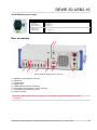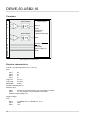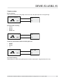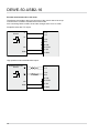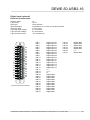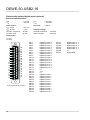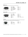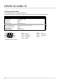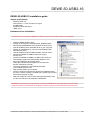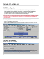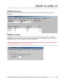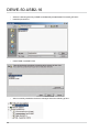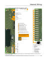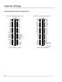
1
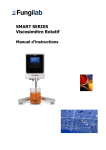
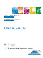
Automotive
Energy & Power Analysis
Field Service
Environmental
Research & Development
DEWE-50-USB2-16
Technical reference manual
ISO9001
... the precision signal conditioning company
www.dewetr o n .c om
Copyright © DEWETRON elektronische Messgeraete Ges.m.b.H.
This document contains information which is protected by copyright. All rights are reserved. Reproduction,
adaptation, or translation without prior written permission is prohibited, except as allowed under the copyright laws.
All trademarks and registered trademarks are acknowledged to be the property of their owners.
Technical Reference
Content
General Information, Safety Instructions
5
Warranty Information… ……………………………………………………………………… 5
Support………………………………………………………………………………………… 5
Printing History………………………………………………………………………………… 5
Safety symbols in the manual… …………………………………………………………… 6
Safety instructions for all DEWETRON systems… ……………………………………… 7
Environmental Considerations… …………………………………………………………… 8
DEWE-50-USB2-16
9
Specifications… ……………………………………………………………………………… 9
Internal wiring including all options… ……………………………………………………… 10
DT 9834 AD-board… ………………………………………………………………………… 11
Power supply… ……………………………………………………………………………… 12
Counters… …………………………………………………………………………………… 14
DEWE-50-USB2-16 installation guide……………………………………………………… 21
DEWESoft configuration……………………………………………………………………… 22
CAN setup (AUTO option)…………………………………………………………………… 22
DEWESoft licensing… ……………………………………………………………………… 23
DEWESoft settings…………………………………………………………………………… 23
Synchronisation of more than one DEWE-50-USB2-16… ……………………………… 25
Cable…………………………………………………………………………………………… 26
Trouble shooting… …………………………………………………………………………… 26
Internal Wiring
B1
EC-Certificate of conformity
C1
DE-M070701E • DEWE-50-USB2-16 • Technical Reference Manual • Printing version 1.0.4 • April 16, 2008
3
Technical Reference
4
General Information, Safety Instructions
Notice
The information contained in this document is subject to change without notice.
DEWETRON elektronische Messgeraete Ges.m.b.H. (DEWETRON) shall not be liable for any errors
contained in this document. DEWETRON MAKES NO WARRANTIES OF ANY KIND WITH REGARD
TO THIS DOCUMENT, WHETHER EXPRESS OR IMPLIED. DEWETRON SPECIFICALLY DISCLAIMS
THE IMPLIED WARRANTIES OF MERCHANTABILITY AND FITNESS FOR A PARTICULAR PURPOSE.
DEWETRON shall not be liable for any direct, indirect, special, incidental, or consequential damages,
whether based on contract, tort, or any other legal theory, in connection with the furnishing of this document
or the use of the information in this document.
Warranty Information
A copy of the specific warranty terms applicable to your DEWETRON product and replacement parts can be
obtained from your local sales and service office.
Support
For any support please contact your local distributor first or DEWETRON directly.
For Asia and Europe, please contact:
For the Americas, please contact:
DEWETRON Ges.m.b.H.
Parkring 4
A-8074 Graz-Grambach
AUSTRIA
Tel.: +43 316 3070
Fax: +43 316 307090
Email: [email protected]
Web: http://www.dewetron.com
DEWETRON, Inc.
PO Box 1460
Charlestown, RI 02813
U.S.A.
Tel.:
+1 401 364 9464
Toll-free: +1 877 431 5166
Fax:
+1 401 364 8565
Email: [email protected]
Web:
http://www.dewamerica.com
The telephone hotline is available
Monday to Friday between
08:00 and 17:00 CET (GMT +1:00)
The telephone hotline is available
Monday to Friday between
08:00 and 17:00 GST (GMT -5:00)
Restricted Rights Legend
Use austrian law for duplication or disclosure.
DEWETRON GesmbH
Parkring 4
A-8074 Graz-Grambach / Austria
Printing History
Please refer to the page bottom for printing version.
Copyright © DEWETRON elektronische Messgeraete Ges.m.b.H.
This document contains information which is protected by copyright. All rights are reserved. Reproduction,
adaptation, or translation without prior written permission is prohibited, except as allowed under the copyright
laws.
All trademarks and registered trademarks are acknowledged to be the property of their owners.
DE-M070701E • DEWE-50-USB2-16 • Technical Reference Manual • Printing version 1.0.4 • April 16, 2008
5
Safety instructions
Safety symbols in the manual
Indicates hazardous voltages.
WARNING
Calls attention to a procedure, practice, or condition that could cause bodily
injury or death.
CAUTION
Calls attention to a procedure, practice, or condition that could possibly cause
damage to equipment or permanent loss of data.
WARNINGS
The following general safety precautions must be observed during all phases of operation, service, and
repair of this product. Failure to comply with these precautions or with specific warnings elsewhere in this
manual violates safety standards of design, manufacture, and intended use of the product. DEWETRON
Elektronische Messgeraete Ges.m.b.H. assumes no liability for the customer’s failure to comply with these
requirements.
All accessories shown in this document are available as option
and will not be shipped as standard parts.
6
For safety reasons max. 50 V may be applied to the BNC input-connectors! Refer to the regulation of maximum allowable touch potential.
Safety instructions
Safety instructions for all DEWETRON systems
The DEWETRON data acquisition systems may only be installed by experts.
Read your manual before operating the system.
Observe local laws when using the instrument.
Ground the equipment: For Safety Class 1 equipment (equipment having a protective earth terminal),
a non interruptible safety earth ground must be provided from the mains power source to the product
input wiring terminals or supplied power cable.
DO NOT operate the product in an explosive atmosphere or in the presence of flammable gases or fumes and do not bring the system in contact with water.
DO NOT operate damaged equipment: Whenever it is possible that the safety protection features built into this product have been impaired, either through physical damage, excessive moisture, or any
other reason, REMOVE POWER and do not use the product until safe operation can be verified by
service-trained personnel. If necessary, return the product to a DEWETRON sales and service office
for service and repair to ensure that safety features are maintained.
Keep away from live circuits: Operating personnel must not remove equipment covers or shields.
Procedures involving the removal of covers or shields are for use by service-trained personnel only.
Under certain conditions, dangerous voltages may exist even with the equipment switched off. To
avoid dangerous electrical shock, DO NOT perform procedures involving cover or shield removal
unless you are qualified to do so.
No modifications are allowed at the instrument. The fuse in the power module has to be replaced by
the same type. For continued protection against fire, replace the line fuse(s) only with fuse(s) of the
same voltage and current rating and type. DO NOT use repaired fuses or short-circuited fuse holder
labels and print on the power module may not be removed.
DO NOT service or adjust alone. Do not attempt internal service or adjustment unless another person,
capable of rendering first aid and resuscitation, is present.
DO NOT substitute parts or modify equipment: Because of the danger of introducing additional
hazards, do not install substitute parts or perform any unauthorized modification to the product. Return
the product to a DEWETRON sales and service office for service and repair to ensure that safety
features are maintained.
Before opening the instrument (experts only) or exchanging the fuse in the power module disconnect
power!
Don’t touch internal wiring!
Don’t use higher supply voltage than specified and take care of the correct polarity, otherwise the
system will be damaged!
Use only original plugs and cables for harnessing.
Install filler-panels in unused slots.
The power-cable and -connector serve as Power-Breaker. The cable must not exceed 10 feet,
disconnect function must be possible without tools.
Keep the ventilation slots free and check them frequently to avoid an overheating of the system. The
cleaning interval of the filter pads depends on the environmental conditions.
Safety of the operator and the unit depend on following these rules.
DEWETRON is not responsible for any damage or injury that could result from improper connection or
misuse!
DE-M070701E • DEWE-50-USB2-16 • Technical Reference Manual • Printing version 1.0.4 • April 16, 2008
7
General Information
CAUTION
The system BIOS is protected by password. Any change in the BIOS may cause a system crash.
When the system is booting, do not press ESC-button on keyboard. This may clear the BIOS settings
and cause system faults.
Any change in the file structure as deleting or adding files or directories might cause a system crash.
Before installing software updates contact DEWETRON or your local distributor. Use only software
packages which are released by DEWETRON. Further informations are also available in the internet
(http://www.dewetron.com).
After power off the system wait at least 10 seconds before switching the system on again. Otherwise
the system may not boot correct. This prolongs also the life of all system components.
Environmental Considerations
Information about the environmental impact of the product.
Product End-of-Life Handling
Observe the following guidelines when recycling a DEWETRON system:
System and Components Recycling
Production of these components required the extraction and use of natural resources. The substances
contained in the system could be harmful to your health and to the environment if the system is improperly
handled at it's end of life! Please recycle this product in an appropriate way to avoid an unnecessary pollution
of the environment and to keep natural resources.
This symbol indicates that this system complies with the European Union’s requirements
according to Directive 2002/96/EC on waste electrical and electronic equipment (WEEE).
Please find further informations about recycling on the DEWETRON web site
www.dewetron.com
Restriction of Hazardous Substances
This product has been classified as Monitoring and Control equipment, and is outside the scope of the
2002/95/EC RoHS Directive. This product is known to contain lead.
8
DEWE-50-USB2-16
DEWE-50-USB2-16
16 channel data acquisiston for USB2
Features:
Prepared for up to 16 DAQ or PAD modules
USB interface, easy to use, cable lenght
up to 5 m
12-bit with 100 kS/s or
16-bit up to 500 kS/s (all multiplexed)
Synchronization of several systems
Optional (DEWE-USB2-16-AUTO)
2 x synchronized CAN-bus (up to 1 MBit/s)
5 x counter / encoder channels (isolated)
RS485 interface for EPAD series modules
DC power supply with integrated battery
Specifications
Power supply:
Signal input:
Interface:
Operating temperature:
Storage temperature:
Humidity (operating):
Dimensions (W x D x H):
Weight:
438,5 mm
253 mm
3,3
132,5 mm
Dimensions*
DEWE-50-USB2-16
� 160 W DC NET-202 + accu power supply (10 to 32 V)
� 60 W AC SPS-060-D3 (100 to 250V)
� 50 W DC standard power supply (9 to 36 V)
for details see next pages
DEWE-DAQ series moduels
DEWE-PAD series moduels
DEWE-EPAD series moduels
DEWE-CPAD series modules (opt. for AUTO)
USB2 High-speed
-0 °C to 55 °C
-20 °C to 85 °C
10 % to 80 %, non condensing
approx. 438 x 253 x 135 mm (17.2 x 10 x 5.3 in.)
typ. 7 kg (15.4 lbs), without modules
typ. 8.8 kg (19.3 lbs) fully equipped with DAQP-V-B
* Dimensions in mm
(1 inch = 25.4 mm)
DE-M070701E • DEWE-50-USB2-16 • Technical Reference Manual • Printing version 1.0.4 • April 16, 2008
9
DEWE-50-USB2-16
Internal wiring including all options
Front Pannel
Rear Pannel
DI Panel
DSUB15
DSUB15
DSUB9
DSUB9
DSUB9
DSUB9
DSUB9
DSUB9
DSUB37
Digital I/O
SYNC (option A*,B**)
EPAD
COM
CNT 0 (option A*)
CNT 1 (option A*)
CNT 2 (option A*)
±12V
CNT 3 (option A*)
CNT 4 (option A*)
DI (option A*)
Data Translation DT-9834 AD-board
500kHz Aggregat Samplerate
16 Bit resolution
DEWE-Rack-16
or MDAQ-panel
+5V
16 x BNC
(option D****)
USB 2.0
Highspeed
4 Port Hub
USB
Connector
Channel
0 to 15
RS232-485
Converter
USB-485
Converter
+5V
USB
Connector
AD board
status
LED
DSUB9
Vector
CANcaseXL
(AUTO-option)
DSUB9
±12V
Power Supply
(option C***)
Power
LED
24V NiCd accu
* option A: ** option B: *** option C: ****option D: 10
50-USB2-DIO-PANEL-1
50-USB2-SYNC
50-DC-POW (external 115 or 230 VAC power supply)
50-USB2-16-OUT-5
50-USB2-16-OUT-10
DEWE-50-USB2-16
DT 9834 AD-board
Analog input specifications
Analog input
Number of inputs
Resolution
Programmable gain
Range
Effectiv number of bits
A/D throughput
Single channel
Multiple channel
A/D conversion time
Channel acquisition time
Sample and hold aperture uncertainty
Sample and hold aperture delay
System accuracy (% of FSR)
Gain = 1
Gain = 2 (5 V Range, default range)
Gain = 4
Gain = 8
Bipolar input range
Common Mode Input Voltage
Common Mode rejection ratio
Maximum input voltage without damage
Power on
Power off
Input impedance
Off channel
On channel
Bias current
Nonlinearity
Differential Nonlinearity
Inherent quantizing error
A/D zero drift
Gain drift (of FSR / °C)
Differential Linearity drift (of FSR / °C
up to 32 SE
16-bit
1,2,4,8
16-bit
±10 V, 5 V, 2.5 V, 1.25 V
Successive approximation (SAR)
500 kS/s
500 kS/s (aggragate) ±0.05 %
2 μs
±1/2 LBS, 1 μs typ.
2 ns typ.
50 ns typ.
500 kHz
400 kHz
±0.05 %
±0.03 %
±0.06 %
±0.04 %
±0.07 %
±0.05 %
±0.09 %
±0.07 %
±10 V
±11 V
Gain = 1 @ 1 kΩ 74 dB 80 dB
250 kHz
±0.01 %
±0.02 %
±0.02 %
±0.03 %
±35 V
± -20 V
< -93 dB
100 MΩ, 10 pf
100 MΩ, 10 pf
±20 nA
<1/2 LSB
1/2 LSB
1/2 LSB
±10 μV / °C
±30 ppm / °C
±3 ppm ±2 ppm
DE-M070701E • DEWE-50-USB2-16 • Technical Reference Manual • Printing version 1.0.4 • April 16, 2008
11
DEWE-50-USB2-16
Analog output specifications (optional)
Analog output
Number of outputs
Resolution
Range
Throughput
FIFO
Current output
Output impendance
Protection
Slew rate
Nonlienarity
Differential nonlinearity
Acuuracy
Offset drift
Gain drift
DT 9834 AD-board
4 (routed to Pin 7 of channel 12 to 15)
16-bit
±10 V
500 kS/s/channel
128 kS
5 mA maximum load
0.1 Ω
short circuit to ground
10 V / μs
1 LBS
1 LBS
0.1 % FSR (adjustable)
±10 ppm of FSR / °C
±30 ppm
Power supply
DC NET-202 + accu power supply
The power supply supports DC-UPS function. When the DC supply is lost, the Power LED on the front turns
from green into orange. 30 seconds before the book shuts down, an acoustic beep signal occurs.
DC Power supply
Input:
DC and battery input:
Max. input current:
Input power:
Input voltage priority:
Battery type:
Output:
Output power:
Output voltages:
Power LED:
dim green:
bright green:
orange:
red:
NET-202 DC + Accu
10 to 32 VDC
startup peak up to 25 A
160 W
1. DC voltage
2. Accu
NiCd, 24 VDC, 600 mAh
160 W
+5 V (max. 20 A)
+12 V (max. 5 A)
-5 V (max. 0.3 A)
-12 V (max. 0.4 A)
DC connected to system, system powered off
DC connected to system, system powered on
system powered on, working via accu
starts 30 sec. before accu is getting low together with beep signal
DC AVP-2B/K (standard power supply)
DC Power supply
Input:
DC input:
Max. input current:
Input power:
Output:
Output power:
Output voltages:
Protection:
Fuse:
12
AVP-2B/K
9 to 40 VDC
5.6 A
160 W
max. 51 W
+12 V (max. 2 A)
-12 V (max. 2 A)
Overvoltage protection, excess temperature protection, polarity reversal protection
6.3 A
DEWE-50-USB2-16
AC SPS-060-D3 power supply
60 W AC power supply
Input:
Input range:
Input frequency:
Max. input current:
Output:
Output power:
Output voltages:
SPS 060P-D3
100 to 250 VAC
47 to 63 Hz or DC
1.8 A @ 230 VDC
60 W
+12 V
-12 V
(max. 3.4 A)
(max. 3.4 A)
Rear connectors
1
2
6 5
3
4
7
8
Typical DEWE-50-USB2-16-AUTO rear view
1.) RS485 & synchronization connector
2.) Serial port
3.) Counter input
4.) Digital input
5.) USB2 interface (connect to the PC)
6.) free USB2 port (for webcam or dasy chaining)
7.) 2 CAN ports (manufacturer vector)
8.) Power connector
Note: The location of the connectors might vary from system to system and depends on system
configuration
DE-M070701E • DEWE-50-USB2-16 • Technical Reference Manual • Printing version 1.0.4 • April 16, 2008
13
DEWE-50-USB2-16
Counters
300V isolation
B+
6
32 Bit counter
Source
A-
7
1
300V isolation
A+
2
Event
Event/Time
Freqency
Up/down (Encoder)
Gate
B-
Counter / Encoder
X1 / X4
5V Supply
Sensor supply V+
GND
DSUB9
8
9
5
3
4
Block diagram of counter 0 to 7
Electrical characteristics
Counter / encoder input pairs (A+; A-; B+; B-)
Pins:
PIN 1
PIN 2
PIN 6
PIN 7
B+
A+
BA-
Logic low:
0 to 2 V
Logic high:
4 to 50 V
Bandwidth:
5 MHz
Galvanic isolated (300 V)
Selection pins
PIN 8
Counter to encoder selection (not connected is counter)
PIN 9
X1 / X4 selection (not connected is X4 mode)
maximum input voltage: TTL
Supply voltage:
Pins:
14
PIN 3
PIN 4
PIN 5
V+ (DEWE-50: 12 V DEWE-51: 15 V)
GND
+5 V
DEWE-50-USB2-16
Counter modes
Event counting
The counter counts every rising edge of the source pin; the gate input has to be logical high.
Frequency generator
+
2 A+
GND
7 A-
CNT
Event per time counting
•
•
•
•
100 ms
200 ms
500 ms
sample rate
Frequency generator
+
2 A+
GND
7 A-
CNT
Frequency measurement with selectable gate time
•
•
•
•
100 ms
200 ms
500 ms
1s
Frequency generator
+
2 A+
GND
7 A-
CNT
Up / down counting
Depending on the state of the gate input; the counter counts up if it´s high and down if it´s low.
DE-M070701E • DEWE-50-USB2-16 • Technical Reference Manual • Printing version 1.0.4 • April 16, 2008
15
DEWE-50-USB2-16
Encoder measurement X1 or X4 mode
Therefore a wire bridge in the input connector of the counter has to be set up.
Connect PIN 4 to PIN 8 to activate the encoder mode.
Also connecting PIN 9 to GND, the encoder changes from X4 to X1 mode.
Simple Encoder with TTL output:
Quadratur Encoder
A
Sensor
B
2 A+
CNT
7 A1 B+
6 B8 C/Q
12V
GND
9 X1/X4
3 12V
4 GND
High speed encoder with differential output:
Quadratur Encoder
A
Sensor
A
2 A+
7 A-
B
B
1 B+
6 B-
CNT
8 C/Q
12V
GND
16
9 X1/X4
3 12V
4 GND
DEWE-50-USB2-16
Digital input (optional)
Electrical characteristics:
Number of DIO:
Logic family:
Input type:
Input termination:
Input logic load:
Logic high input voltage:
Logic low input voltage:
Logic low input current:
1
2
3
4
5
6
7
8
9
10
11
12
13
14
15
16
17
18
19
20
21
22
23
24
25
26
27
28
29
30
31
32
33
34
35
36
37
37-pin female DSUB connector
16
LVTTL
Level sensitive
Input tieds to +3.3 V with 15 kΩ pullup resistors
1 LVTTL load
2.0 V minimum
0.8 V maximum
-0.4 mA maximum
PIN 1:
PIN 2:
PIN 3:
PIN 4:
PIN 5:
PIN 6:
PIN 7:
PIN 8:
PIN 9:
PIN 10:
PIN 11:
PIN 12: PIN 13:
PIN 14:
PIN 15:
PIN 16:
PIN 17:
PIN 18:
PIN 19:
PIN 20: PIN 21:
PIN 22:
PIN 23:
PIN 24:
PIN 25:
PIN 26:
PIN 27:
PIN 28:
PIN 29:
PIN 30:
Digital Input 00
Digital input 01
Digital input 02
Digital input 03
Digital input 04
Digital input 05
Digital input 06
Digital input 07
Digital input 08
Digital input 09
Digital input 10
Digital input 11
Digital input 12
Digital input 13
Digital input 14
Digital input 15
n.c
+5 V
V+
Digital GND
Digital GND
Digital GND
Digital GND
Digital GND
Digital GND
Digital GND
Digital GND
Digital GND
Digital GND
Digital GND
PIN 31:
PIN 32:
PIN 33:
PIN 34:
PIN 35:
PIN 36:
PIN 37:
DE-M070701E • DEWE-50-USB2-16 • Technical Reference Manual • Printing version 1.0.4 • April 16, 2008
Digital GND
Digital GND
Digital GND
Digital GND
Digital GND
n.c
Digital GND
17
DEWE-50-USB2-16
Galvanically isolated digital input (optional)
Electrical characteristics:
Uoff Uon < 1.8 Volt
> 3.2 Volt
TON
TOFF
< 160 nsec
< 160 nsec
Input current:
Bandwidth
> 3MHz
UIN= 5 Volt
UIN= 30 Volt
UIN max. continuous: UIN max. peak: Isolation voltage:
Channel to Channel
Input to Output
< 3.5 mA
< 7 mA
35 Volt
65 Volt
100 VDC
250 VDC
Input Levels:
L= Low
H= High
1
2
3
4
5
6
7
8
9
10
11
12
13
14
15
16
17
18
19
20
21
22
23
24
25
26
27
28
29
30
31
32
33
34
35
36
37
37-pin female DSUB connector
18
PIN 1:
PIN 2:
PIN 3:
PIN 4:
PIN 5:
PIN 6:
PIN 7:
PIN 8:
PIN 9:
PIN 10:
PIN 11:
PIN 12: PIN 13:
PIN 14:
PIN 15:
PIN 16:
PIN 17:
PIN 18:
PIN 19:
PIN 20: PIN 21:
PIN 22:
PIN 23:
PIN 24:
PIN 25:
PIN 26:
PIN 27:
PIN 28:
PIN 29:
PIN 30:
Digital Input 00 H
Digital input 01 H
Digital input 02 H
Digital input 03 H
Digital input 04 H
Digital input 05 H
Digital input 06 H
Digital input 07 H
Digital input 08 H
Digital input 09 H
Digital input 10 H
Digital input 11 H
Digital input 12 H
Digital input 13 H
Digital input 14 H
Digital input 15 H
n.c.
+5 V
n.c.
Digital Input 00 L
Digital Input 01 L
Digital Input 02 L
Digital Input 03 L
Digital Input 04 L
Digital Input 05 L
Digital Input 06 L
Digital Input 07 L
Digital Input 08 L
Digital Input 09 L
Digital Input 10 L
PIN 31:
PIN 32:
PIN 33:
PIN 34:
PIN 35:
PIN 36:
PIN 37:
Digital Input 11 L
Digital Input 12 L
Digital Input 13 L
Digital Input 14 L
Digital Input 15 L
n.c.
Digital GND
DEWE-50-USB2-16
RS485 & sync
For detailed information about synchronizing more devices refer to page ..
8 7 6 5 4 3 2 1
15 14 13 12 11 10 9
15-pin DSUB female connector
PIN 1:
PIN 2:
PIN 3:
PIN 4:
PIN 5:
PIN 6:
PIN 7:
PIN 8:
RS485A
RS485 B
Digital GND
EXT AD-trigger
Digital GND
AD-Clock out
n.c
n.c
PIN 9:
PIN 10:
PIN 11:
PIN 12:
PIN 13:
PIN 14:
PIN 15:
n.c
n.c
n.c
n.c
n.c
n.c
n.c
PIN 9:
PIN 10:
PIN 11:
PIN 12:
PIN 13:
PIN 14:
PIN 15:
n.c
n.c
n.c
n.c
n.c
GND
V+ (max. 800 mA)
RS485 & EPAD
This connector can be used to supply up to 8 EPAD moduels
8 7 6 5 4 3 2 1
15 14 13 12 11 10 9
15-pin DSUB female connector
PIN 1:
PIN 2:
PIN 3:
PIN 4:
PIN 5:
PIN 6:
PIN 7:
PIN 8:
RS485A
RS485 B
Digital GND
n.c
n.c
n.c
n.c
n.c
COM port
The COM port can be used to control the DEWETRON modules instead of the internal USB to RS485
converter. In special cases it could also be used as a serial configuration port.
5 4 3 2 1
9 8 7 6
PIN 1:
PIN 2:
PIN 3:
PIN 4:
PIN 5:
n.c
to PC RX
to PC TX
n.c
to PC GND
PIN 6:
PIN 7:
PIN 8:
PIN 9:
n.c
n.c
n.c
n.c
9-pin DSUB female connector
DE-M070701E • DEWE-50-USB2-16 • Technical Reference Manual • Printing version 1.0.4 • April 16, 2008
19
DEWE-50-USB2-16
CAN bus (AUTO option)
The used CAN device is a vector CANCaseXL.
For detailed information regarding the CAN interface refer to the Vector CANCaseXL manual.
Specifications
Microcontroller:
CAN controller:
CAN version:
PC interface:
Operatin system:
Error frame / Remote frame:
Board dimension approx.:
Current consuption typ.:
Supply voltage:
Standard piggyback:
ATMEL AT91 (ARM7 TDMI 64 Mhz)
2 x Phillips SJA 1000
CAN 2.0B
USB2.0
Windows 2000, XP
Detection & generation
105 x 85 x 32 mm (4.1 x 3.3 x 1.3 in.)
250 mA
7 to 33 V
CAN 1050 OPTO
5 4 3 2 1
9 8 7 6
9-pin DSUB female connector
20
PIN 1:
PIN 2:
PIN 3:
PIN 4:
PIN 5:
n.c
CAN low
GND (Vb-)
reserved
shield
PIN 6:
PIN 7:
PIN 8:
PIN 9:
n.c
CAN high
reserved
n.c
DEWE-50-USB2-16
DEWE-50-USB2-16 installation guide
System requirements
Windows 2000 / XP
Intel Pentium 4, 1 GHz processor or higher
512 MB RAM
50 MB free hard disk space
USB2.0 port
Hardware driver installation
CAUTION: do not connect the DEWE-50-USB2-16 to the PC until all the drivers are installed!
•
•
•
•
•
•
•
•
•
•
•
•
•
•
•
Insert the DEWE-System DVD
Change to the directory \Install\Drivers\6_DAQBoards\DT
Start the SetupOEMWin32.exe and follow the instructions.
This will install the basic AD-board driver to your computer.
Change to \Install\Drivers\7_Communication\DEWE-USB
Start TI3410inst.exe
This will install the internal USB to RS485 converter driver.
Connect the DEWE-50-USB2 to the power supply
and turn it on.
Connect the DEWE-50-USB2 to a USB2.0 port of the PC.
The operating system will automatically detect the new
device and install the appropriate driver.
Follow the individual driver setups from the AD-board
and the USB-serial-converter.
The vector CAN driver is automatically detected
on the DEWE-System DVD.
After finishing restart your computer.
Check in the device manager if everything is installed properly.
If there is a device missing or marked with a yellow sign proceed
with trouble shooting on page..
Keep the COM port number of the USB-serial-port within mind.
It is the port that has to be selected in DEWESoft.
WARNING: It is strongly recommended to connect the DEWE-50 to the same USB connector of the
computer all the time. Otherwise the COM port number changes and the installation becomes slow.
DE-M070701E • DEWE-50-USB2-16 • Technical Reference Manual • Printing version 1.0.4 • April 16, 2008
21
DEWE-50-USB2-16
DEWESoft configuration
•
To configure your modules in the DEWETRON-system please install the software “DEWESoft” from your system-DVD and choose the option “DEWESoft for DEWEConfig mode” After the installation please start DEWESoft and enter the COM port where your modules are connected. (Note: Please don´t change the setting “Analog device” - it should be set to “No A/D Hardware”). Confirm the new settings with “OK”, exit this menu and choose “Setup”. Inthis overview you can add / remove modules and change the ranges and the addresses.
(A detailed description can be found in the online manual of DEWESoft.)
NOTE: This steps above only have to be made if you did not order DEWESoft with your DEWE-50-USB216 and want to install your system afterwards. Otherwise refer to the following steps of the DEWESoft
configuration chapter.
After installing DEWESoft you have to make following settings in the hardware setup:
•
•
Select as analog device “Data translation”
Select as COM port the internal USB-serial-port of the DEWE-50-USB2-16. It is listed as “USB-serial-
port” in your device manager
CAN setup (AUTO option)
Select the vector CAN driver in DEWESoft
22
DEWE-50-USB2-16
DEWESoft licensing
Enter in the hardware setup of DEWESoft the license keys from the license certificate you got with your
DEWESoft.
DEWESoft settings
DEWESoft automatically changes to the multi-board-mode if it detects more than one device installed in
the system. If you do not want to do this, it is possible to deactivate it in the DEWESoft tuner located in the
DEWESoft directory. Also the master board can be changed there.
WARNING: If DEWESoft is in mutli-board-driver-mode and there is no external sync cable it would not
measure. (Measured values will be zero all the time.)
DE-M070701E • DEWE-50-USB2-16 • Technical Reference Manual • Printing version 1.0.4 • April 16, 2008
23
DEWE-50-USB2-16
Example of DEWESoft hardware setup
24
DEWE-50-USB2-16
Synchronisation of more than one DEWE-50-USB2-16
How does it work
The synchronization of more than one DEWE-50-USB2 device is realized by using counter 0 of the master
device for generating the sample clock for all devices. This includes the following limitations. The maximum
sample rate is the half sample rate of the slowest device that is synchronized. The counter 0 of the master
board could not be used for anything else.
Wiring
MASTER
DSUB15
DEWE-BOOK-DT
1
Rs485 A
1
Rs485 B
2
EXT AD-Trigger
4
Digital GND
5
EXT AD-Clock
6
MASTER Clock
LED
DSUB15
DEWE-BOOK-DT
1
Rs485 A
1
Rs485 B
2
EXT AD-Trigger
4
Digital GND
5
EXT AD-Clock
6
DSUB15
DEWE-BOOK-DT
1
Rs485 A
1
Rs485 B
2
EXT AD-Trigger
4
Digital GND
5
EXT AD-Clock
6
Next device
DE-M070701E • DEWE-50-USB2-16 • Technical Reference Manual • Printing version 1.0.4 • April 16, 2008
25
DEWE-50-USB2-16
Cable
Connector
Connector
Connector
1
1
1
1
2
2
2
2
4
4
4
4
5
5
5
5
6
6
15-pin DSUB
15-pin DSUB
Connector
Sync cable
15-pin DSUB
15-pin DSUB
Masters sync cable
Trouble shooting
Q: DEWESoft doesn´t find the DAQP or PAD module. What can i do?
A: Be sure that the rigth COM port is selected in DEWESoft. It should be the one, which is mentioned as USB-serial port in the device manager.
Q: No USB-serial port is visible in the device manager. How can I reinstall it?
A: •
Double click on the device
•
Click on
•
Select
26
DEWE-50-USB2-16
•
Select multi-port serial adapter
•
Press on "Have disk"
DE-M070701E • DEWE-50-USB2-16 • Technical Reference Manual • Printing version 1.0.4 • April 16, 2008
27
DEWE-50-USB2-16
•
•
Select the following directory \DEWE-50-USB2\USB_RS485\DISK1\TI3410XP_DEVICE1
Install UmpComXP.inf
•
Install TUSB 3410UART EVM
•
After succesfully installation the device manager shows the following picture
28
DEWE-50-USB2-16
Q: An error messages occurs when using maximum sampling rate. What can I do?
A: The used USB connector might not be USB 2.0 standard
Q: CAN device not found! Why?
A: Insert the DEWE-System DVD in your system and go to the directory \Install\Drivers\X_Various\Vector_
CAN_53 and install the drivers manually.
DE-M070701E • DEWE-50-USB2-16 • Technical Reference Manual • Printing version 1.0.4 • April 16, 2008
29
DEWE-50-USB2-16
Notes
30
Internal Wiring
Internal Wiring
16 slot DEWE-MOTHERBOARD DAQ-MOTH-16-DE-x
Rear view
W7
5 = 5 V output; 330 kHz filter
10 = 10 V output; 330 kHz filter
GND
+15 V ORION
-15 V ORION
W1
W10
CH 0
Front view
CH 1
W11
16 channels single ended
analog output
(output resistance 15 Ohm)
Please find the pin-assignment
on the next page!
W8
CH 2
CH 3
5 V ORION
Ext. CLK
Ext. TRIG
DGND ORION
Ext. CLK 2 OUT
Ext. CLK 1 OUT (CAMERA TRIGGER)
W9
CH 4
CH 5
DGND ORION
W5
CH 6
W1
16x GND
16 x analog OUT (resistance 50 Ohm)
GND
W2
W3
W4
W5
W6
W7
W8
W9
Terminate RS-485
Connect GND to GNDP
Connect +12 V to +V (pin 6)
Terminate RS-485
Connect chassis to GND
Connect chassis to GND
Connect chassis to GND
Activate ORION RS-485 (A)
Activate ORION RS-485 (B)
CH 7
CH 8
CH 9
CH 10
CH 11
W10
W11
Activate analog output 0 on CH 14
Activate analog output 1 on CH 15
Note: If you connect signals to these
contacts you have to open the solder
jumpers W10 and W11 first!
CH 12
CH 13
CH 14
Connection to CH14 (pin 7)
Connection to CH15 (pin 7)
Indicator
+9 V
-9 V
CH 15
1 2 3 4 5
W4
+V
+12 V
GNDP
-12 V
-V
GNDC
GNDC
TX
RX
1
2
3
4
5
6
7
8
9
RS-232
9-pin SUB-D pin assignment:
A (RS-485)
GNDC
B (RS-485)
GNDP
+V
+12 V
-12 V
-V
RS-485
RS-485
W3
6 7 8 9
GND
POWER
W2
W6
POWER
DM
DP
GNDC
RX
TX
GNDC
B
B
A
A
USB
RES
GND
Module input (±5 V)
RS-485 (A)
RS-485 (B)
GND
+9 V power supply
+12 V power (default) /
+V sensor supply
Module output
(from A/D board)
-V sensor supply
-9 V power supply
The 16 slot DEWE-MOTHERBOARD receives the ±12 VDC power supply via a DC/DC converter from the
internal power supply.
DE-M070701E • DEWE-50-USB2-16 • Technical Reference Manual • Printing version 1.0.4 • April 16, 2008
B1
Internal Wiring
Analog output connector pin-assignment
Connector for DEWE-ORION-1616 cards
+15 V
AGND
AGND
AGND
AGND
AGND
AGND
AGND
AGND
AGND
AISENSE2
AGND
AGND
AGND
AGND
AGND
AGND
AGND
AISENSE1
AGND
DI8/DO0
DI9/DO1
DI10/DO2
DI11/DO3
DI12/DO4
DI13/DO5
DI14/DO6
DI15/DO7
+5 V
DGND
DGND
+5 V
DGND
DGND
35
36
37
38
39
40
41
42
43
44
45
46
47
48
49
50
51
52
53
54
55
56
57
58
59
60
61
62
63
64
65
66
67
68
1
2
3
4
5
6
7
8
9
10
11
12
13
14
15
16
17
18
19
20
21
22
23
24
25
26
27
28
29
30
31
32
33
34
-15 V
AGND
AGND
CH15+
CH14+
CH13+
CH12+
CH11+
CH10+
CH9+
CH8+
CH7+
CH6+
CH5+
CH4+
CH3+
CH2+
CH1+
CH0+
AGND
DI0/Source(0)
DI1/Gate(0)
DI2/AUX_U_D(0)
DI3/Source(1)
DI4/Gate(1)
DI5/AUX_U_D(1)
RS-485A
RS-485B
DI 6
DI 7
EXT_CLK
EXT_Trigger
EXT_CLK1
EXT_CLK2
Connector for DEWE-ORION-1624 cards
+15V
AGND
AGND
CH. 15CH. 14CH. 13CH. 12CH. 11CH. 10CH. 9CH. 8CH. 7CH. 6CH. 5CH. 4CH. 3CH. 2CH. 1CH. 0AGND
NC.
NC.
NC.
NC.
NC.
NC.
NC.
NC.
+5 V
DGND
DGND
+5 V
DGND
DGND
35
36
37
38
39
40
41
42
43
44
45
46
47
48
49
50
51
52
53
54
55
56
57
58
59
60
61
62
63
64
65
66
67
68
1
2
3
4
5
6
7
8
9
10
11
12
13
14
15
16
17
18
19
20
21
22
23
24
25
26
27
28
29
30
31
32
33
34
-15 V
AGND
AGND
CH. 15+
CH. 14+
CH. 13+
CH. 12+
CH. 11+
CH. 10+
CH. 9+
CH. 8+
CH. 7+
CH. 6+
CH. 5+
CH. 4+
CH. 3+
CH. 2+
CH. 1+
CH. 0+
AGND
NC.
NC.
NC.
NC.
NC.
NC.
RES.*
RES.*
RES.*
RES.*
RES.*
EXT-TRIGGER
SAMPLE CLOCK
NC.
* DONT CONNECT
68-pin high density connector
B2
68-pin high density connector
EC-Certificate of conformity
EC-Certificate of conformity
Manufacturer:
DEWETRON Elektronische Messgeraete Ges.m.b.H.
Address: Parkring 4
A-8074 Graz-Grambach Austria
Tel.: +43 316 3070 0
Fax: +43 316 3070 90
e-mail: [email protected]
http://www.dewetron.com
Name of product:
DEWE-50-USB2-16
Kind of product:
ADC Rack
The product meets the regulations of the following EC-directives:
73/23/EEC
"Directive on the approximation of the laws of the Member States relating to
electrical equipment designed for use within certain voltage limits amended by
the directive 93/68/EEC"
89/336/EEC
"Directive on the approximation of the laws of the Member States relating to
electromagnetic compatibility amended by the directives 91/263/EEC, 92/31/
EEC, 93/68/EEC and 93/97/EEC
The accordance is proved by the observance of the following standards:
L
V
E
M
C
Safety
IEC/EN 61010-1:1992/93
IEC/EN 61010-2-031
IEC 61010-1:1992/300 V CATIII Pol. D. 2
IEC 1010-2-031
Emissions
EN 61000-6-4
EN 55011 Class B
Immunity
EN 61000-6-2
Group standard
Graz, Nov. 15th, 2004
Place / Date of the CE-marking
Ing. Herbert Wernigg / Managing director
DE-M070701E • DEWE-50-USB2-16 • Technical Reference Manual • Printing version 1.0.4 • April 16, 2008
C1
Notes
C2