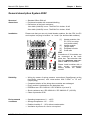
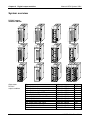
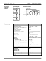
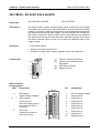
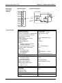
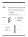
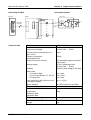
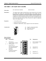
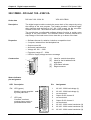
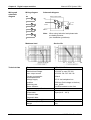
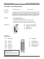
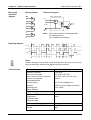
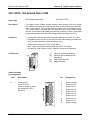
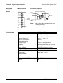
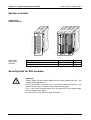
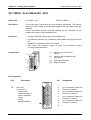
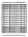
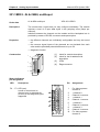
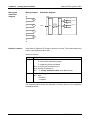
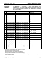
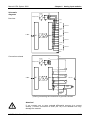
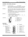
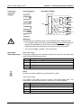
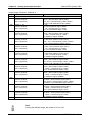
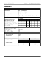
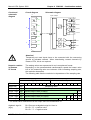
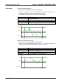
1
Manual VIPA System 200V SM Order No.: VIPA HB97E_SM Rev. 09/19 Lerrzeichen Manual VIPA System 200V About this manual The information contained in this manual is supplied without warranties. The information is subject to change without notice. © Copyright 2009 VIPA, Gesellschaft für Visualisierung und Prozessautomatisierung mbH Ohmstraße 4, D-91074 Herzogenaurach, Tel.: +49 (91 32) 744 -0 Fax.: +49 (91 32) 744-1864 EMail: [email protected] http://www.vipa.de Hotline: +49 (91 32) 744-1150 All rights reserved Disclaimer of liability The contents of this manual were verified with respect to the hard- and software. However, we assume no responsibility for any discrepancies or errors. The information in this manual is verified on a regular basis and any required corrections will be included in subsequent editions. Suggestions for improvement are always welcome. Trademarks VIPA, System 100V, System 200V, System 300V and System 500V are registered trademarks of VIPA Gesellschaft für Visualisierung und Prozessautomatisierung mbH. SPEED7 is a registered trademark of profichip GmbH. STEP und S7-300 are registered trademarks of Siemens AG. Any other trademarks referred to in the text are the trademarks of the respective owner and we acknowledge their registration. Subject to change to cater for technical progress. About this manual Manual VIPA System 200V About this manual This manual describes the System 200V SM modules that are available from VIPA. In addition to the product summary it contains detailed descriptions of the different modules. You are provided with information on the connection and the utilization of the System 200V SM modules. Every chapter is concluded with the technical data of the respective module. Overview Chapter 1: Basics This introduction presents the VIPA System 200V as a centralized as well as decentralized automation system. The chapter also contains general information about the System 200V, i.e. dimensions, installation and operating conditions. Chapter 2: Assembly and installation guidelines This chapter provides all the information required for the installation and the hook-up of a controller using the components of the System 200V. Chapter 3-5: Digital input/output modules These chapters describe the digital remote I/O that is available from VIPA. It provides all the information that is required for applications using these modules. Chapter 3 contains information on the input modules, chapter 4 the information on the output modules and chapter 5 provides details on input/output modules. Chapter 6-8: Analog input/output modules These chapters contain a description of the analog remote I/O. The chapter also provides all the information that is required for applications using each module. Chapter 6 describes the input modules, chapter 7 the output modules and chapter 8 the analog input/output modules that are available from VIPA. Chapter 9: SM238C - Combination module In this chapter follows the description of the combination module SM 238C that includes a digital in-/output module with counter function and an analog in-/output module. Subject to change to cater for technical progress. Manual VIPA System 200V Contents Contents User considerations ................................................................................. 1 Safety information .................................................................................... 2 Chapter 1 Basics .............................................................................. 1-1 Safety Information for Users................................................................. 1-2 Overview .............................................................................................. 1-3 Components......................................................................................... 1-4 General description System 200V ........................................................ 1-5 Chapter 2 Assembly and installation guidelines............................ 2-1 Overview .............................................................................................. 2-2 Assembly.............................................................................................. 2-5 Wiring................................................................................................... 2-8 Assembly dimensions......................................................................... 2-10 Installation guidelines ......................................................................... 2-12 Chapter 3 Digital input modules...................................................... 3-1 System overview .................................................................................. 3-2 221-1BF00 - DI 8xDC 24V.................................................................... 3-4 221-1BF10 - DI 8xDC 24V 0.2ms ......................................................... 3-6 221-1BF20 - DIa 8xDC 24V.................................................................. 3-8 221-1BF21 - DIa 8xDC 24V 0.2ms ..................................................... 3-10 221-1BF30 - DI 8xDC 24V - ECO....................................................... 3-12 221-1BF40 - DI 8xDC 24V 0.2ms ....................................................... 3-14 221-1BF50 - DI 8xDC 24V NPN ......................................................... 3-16 221-1FD00 - DI 4xAC/DC 90...230V................................................... 3-18 221-1FF20 - DI 8xAC/DC 60...230V ................................................... 3-20 221-1FF30 - DI 8xAC/DC 24...48V ..................................................... 3-22 221-1FF40 - DI 8xAC 240V ................................................................ 3-24 221-1FF50 - DI 8xAC/DC 180...265V ................................................. 3-26 221-1BH00 - DI 16xDC 24V with UB4x .............................................. 3-28 221-1BH10 - DI 16xDC 24V ............................................................... 3-30 221-1BH20 - DI 16xDC24V/1C........................................................... 3-32 221-1BH30 - DI 16xDC 24V - ECO .................................................... 3-42 221-1BH50 - DI 16xDC 24V NPN with UB4x ...................................... 3-44 221-1BH51 - DI 16xDC 24V NPN....................................................... 3-46 221-2BL10 - DI 32xDC 24V................................................................ 3-48 Chapter 4 Digital output modules ................................................... 4-1 System overview .................................................................................. 4-2 222-1BF00 - DO 8xDC 24V 1A ............................................................ 4-4 222-1BF10 - DO 8xDC 24V 2A ............................................................ 4-6 222-1BF20 - DO 8xDC 24V 2A separated 4 á 2................................... 4-8 222-1BF30 - DO 8xDC 24V 0.5A - ECO............................................. 4-10 222-1BF50 - DO 8xDC 24V 0.5A NPN ............................................... 4-12 222-1BH00 - DO 16xDC 24V 0.5A with UB4x .................................... 4-14 222-1BH10 - DO 16xDC 24V 1A ........................................................ 4-16 222-1BH20 - DO 16xDC 24V 2A ........................................................ 4-18 222-1BH30 - DO 16xDC 24V 0.5A - ECO .......................................... 4-20 222-1BH50 - DO 16xDC 24V 0.5A NPN............................................. 4-22 222-1BH51 - DO 16xDC 24V 0.5A NPN............................................. 4-24 222-2BL10 - DO 32xDC 24V 1A......................................................... 4-26 222-1DB00 - DO 2xAC 100...230V 2A ............................................... 4-28 222-1HF00 - DO 8xRelay COM.......................................................... 4-37 222-1HD10 - DO 4xRelay................................................................... 4-39 HB97E - SM - Rev. 09/19 i Contents Manual VIPA System 200V 222-1HD20 - DO 4xRelay bistable ..................................................... 4-41 222-1FF00 - DO 8xSolid State COM .................................................. 4-43 222-1FD10 - DO 4xSolid State........................................................... 4-45 Chapter 5 Digital input/output modules.......................................... 5-1 System overview .................................................................................. 5-2 Security hints for DIO modules............................................................. 5-2 223-1BF00 - DIO 8xDC 24V 1A ........................................................... 5-3 223-2BL10 - DI 16xDC 24V, DO 16xDC 24V 1A .................................. 5-5 Chapter 6 Analog input modules..................................................... 6-1 System overview .................................................................................. 6-2 General ................................................................................................ 6-3 231-1BD30 - AI 4x12Bit ±10V - ECO.................................................... 6-6 231-1BD40 - AI 4x12Bit 4...20mA, ±20mA - ECO .............................. 6-11 231-1BD52 - AI 4x16Bit, multiinput..................................................... 6-16 231-1BD53 - AI 4x16Bit, multiinput..................................................... 6-24 231-1BD60 - AI 4x12Bit, 4 ... 20mA, isolated ..................................... 6-38 231-1BD70 - AI 4x12Bit, ±10V, isolated ............................................. 6-41 231-1BF00 - AI 8x16Bit ...................................................................... 6-44 231-1FD00 - AI 4x16Bit f .................................................................... 6-54 Chapter 7 Analog output modules .................................................. 7-1 System overview .................................................................................. 7-2 General ................................................................................................ 7-3 Analog value ........................................................................................ 7-4 232-1BD30 - AO 4x12Bit ±10V, 0 ... 10V - ECO................................... 7-7 232-1BD40 - AO 4x12Bit, 0/4...20mA - ECO ...................................... 7-12 232-1BD51 - AO 4x12Bit, multioutput................................................. 7-17 Chapter 8 Analog input/output modules......................................... 8-1 System overview .................................................................................. 8-2 Security note for range allocation ......................................................... 8-2 General ................................................................................................ 8-3 234-1BD50 - AI 2/AO 2x12Bit - Multiin-/output ..................................... 8-4 234-1BD60 - AI 4/AO 2x12Bit - Multiin-/output ................................... 8-17 Chapter 9 SM 238C - Combination module .................................... 9-1 Overview .............................................................................................. 9-2 In-/Output part ...................................................................................... 9-3 Analog part........................................................................................... 9-4 Analog part - Project engineering ......................................................... 9-7 Analog part - Alarm and diagnostic .................................................... 9-13 Digital part .......................................................................................... 9-15 Digital part - Counter - Fast introduction............................................. 9-17 Digital part - Counter - Project engineering ........................................ 9-19 Digital part - Counter - Functions........................................................ 9-24 Digital part - Counter - Operating modes............................................ 9-26 Digital part - Counter - Additional functions ........................................ 9-31 Digital part - Counter - Alarm and diagnostic...................................... 9-37 Technical Data ................................................................................... 9-40 Appendix ..........................................................................................A-1 Index ....................................................................................................A-1 ii HB97E - SM - Rev. 09/19 Manual VIPA System 200V User considerations User considerations Objective and contents This manual describes the modules that are suitable for use in the System 200V. It contains a description of the construction, project implementation and the technical data. Target audience The manual is targeted at users who have a background in automation technology. Structure of the manual The manual consists of chapters. Every chapter provides a self-contained description of a specific topic. Guide to the document The following guides are available in the manual: • an overall table of contents at the beginning of the manual • an overview of the topics for every chapter • an index at the end of the manual. Availability The manual is available in: • printed form, on paper • in electronic form as PDF-file (Adobe Acrobat Reader) Icons Headings Important passages in the text are highlighted by following icons and headings: Danger! Immediate or likely danger. Personal injury is possible. Attention! Damages to property is likely if these warnings are not heeded. Note! Supplementary information and useful tips. HB97E - SM - Rev. 09/19 1 Safety information Manual VIPA System 200V Safety information Applications conforming with specifications The System 200V is constructed and produced for: • all VIPA System 200V components • communication and process control • general control and automation applications • industrial applications • operation within the environmental conditions specified in the technical data • installation into a cubicle Danger! This device is not certified for applications in • in explosive environments (EX-zone) Documentation The manual must be available to all personnel in the • project design department • installation department • commissioning • operation The following conditions must be met before using or commissioning the components described in this manual: • Modification to the process control system should only be carried out when the system has been disconnected from power! • Installation and modifications only by properly trained personnel • The national rules and regulations of the respective country must be satisfied (installation, safety, EMC ...) Disposal 2 National rules and regulations apply to the disposal of the unit! HB97E - SM - Rev. 09/19 Manual VIPA System 200V Chapter 1 Basics Chapter 1 Basics Overview The focus of this chapter is on the introduction of the VIPA System 200V. Various options of configuring central and decentral systems are presented in a summary. The chapter also contains the general specifications of the System 200V, i.e. dimensions, installation and environmental conditions. Content Topic Page Basics .............................................................................. 1-1 Chapter 1 Safety information for Users................................................................. 1-1 Overview .............................................................................................. 1-3 Components......................................................................................... 1-4 General description System 200V ........................................................ 1-5 HB97E - SM - Rev. 09/19 1-1 Chapter 1 Basics Manual VIPA System 200V Safety Information for Users Handling of electrostatic sensitive modules VIPA modules make use of highly integrated components in MOSTechnology. These components are extremely sensitive to over-voltages that can occur during electrostatic discharges. The following symbol is attached to modules that can be destroyed by electrostatic discharges. The Symbol is located on the module, the module rack or on packing material and it indicates the presence of electrostatic sensitive equipment. It is possible that electrostatic sensitive equipment is destroyed by energies and voltages that are far less than the human threshold of perception. These voltages can occur where persons do not discharge themselves before handling electrostatic sensitive modules and they can damage components thereby, causing the module to become inoperable or unusable. Modules that have been damaged by electrostatic discharges can fail after a temperature change, mechanical shock or changes in the electrical load. Only the consequent implementation of protection devices and meticulous attention to the applicable rules and regulations for handling the respective equipment can prevent failures of electrostatic sensitive modules. Shipping of electrostatic sensitive modules Modules must be shipped in the original packing material. Measurements and alterations on electrostatic sensitive modules When you are conducting measurements on electrostatic sensitive modules you should take the following precautions: • Floating instruments must be discharged before use. • Instruments must be grounded. Modifying electrostatic sensitive modules you should only use soldering irons with grounded tips. Attention! Personnel and instruments should be grounded when working on electrostatic sensitive modules. 1-2 HB97E - SM - Rev. 09/19 Manual VIPA System 200V Chapter 1 Basics Overview The System 200V The System 200V is a modular automation system for centralized and decentralized applications requiring low to medium performance specifications. The modules are installed directly on a 35mm DIN rail. Bus connectors inserted into the DIN rail provide the interconnecting bus. The following figure illustrates the capabilities of the System 200V: System 200V decentral central DP 200V Profibus Interbus CANopen DeviceNet PC 200V SERCOS Ethernet PC-CPU PLC 200V PLC-CPU PLC-CPU for STEP®5 from Siemens for STEP®7 from Siemens Periphery Dig. IN / Dig. OUT / Anal. IN / Anal. OUT / FM / CP / CM HB97E - SM - Rev. 09/19 1-3 Chapter 1 Basics Manual VIPA System 200V Components Centralized system The System 200V series consists of a number of PLC-CPUs. These are programmed in STEP5 or STEP7 from Siemens. CPUs with integrated Ethernet interfaces or additional serial interfaces simplify the integration of the PLC into an existing network or the connection of additional peripheral equipment. The application program is saved in Flash or an additional plug-in memory module. The PC based CPU 288 can be used to implement operating/monitoring tasks, control applications or other file processing applications. The modules are programmed in C++ or Pascal. The PC 288-CPU provides an active interface to the backplane bus and can therefore be employed as central controller for all peripheral and function modules of the VIPA System 200V. With the appropriate expansion interface the System 200V can support up to 4 rows. Decentralized system In combination with a Profibus DP master and slave the PLC-CPUs or the PC-CPU form the basis for a Profibus-DP network in accordance with DIN 19245-3. The DP network can be configured with WinNCS VIPA configuration tool res. Siemens SIMATIC Manager. Other fieldbus systems may be connected by means of slaves for Interbus, CANopen, DeviceNet, SERCOS and Ethernet. Peripheral modules A large number of peripheral modules are available from VIPA, for example digital as well as analog inputs/outputs, counter functions, displacement sensors, positioners and serial communication modules. These peripheral modules can be used in centralized as well as decentralized mode. Integration over GSD File The functionality of all VIPA system components are available via different GSD-files. For the Profibus interface is software standardized, we are able to guarantee the full functionality by including a GSD-file using the Siemens SIMATIC Manager. For every system family there is an own GSD-file. Actual GSD files can be found at ftp.vipa.de/support. 1-4 HB97E - SM - Rev. 09/19 Manual VIPA System 200V Chapter 1 Basics General description System 200V Structure/ dimensions • Standard 35mm DIN rail • Peripheral modules with recessed labelling • Dimensions of the basic enclosure: 1tier width: (HxWxD) in mm: 76x25.4x74 in inches: 3x1x3 2tier width: (HxWxD) in mm: 76x50.8x74 in inches: 3x2x3 Installation Please note that you can only install header modules, like the CPU, the PC and couplers into plug-in location 1 or 1 and 2 (for double width modules). 1 2 [1] 3 [2] 4 SM 221 IM 253 CAN .0 RD .1 BA .2 .3 0 1 DC24V + - 2 3 .1 4 .2 5 .3 .4 6 .5 X 5 6 7 DI 8xDC24V 1 2 .0 3 .1 4 .2 5 .3 .4 6 7 .5 .6 8 .7 9 1 2 .0 2 3 .1 3 4 .2 4 5 .3 5 .4 6 .4 6 7 .5 7 .5 .6 8 .6 8 .6 .7 9 .7 9 .7 I0 X 2 3 4 SM 221 DI 8xDC24V 1 .0 1 2 SM 221 DI 8xDC24V 1 ER ADR. SM 221 DI 8xDC24V PW I0 X 2 3 4 I0 X 2 3 4 7 8 9 I0 X 2 3 4 VIPA 253-1CA00 VIPA 221-1BF00 VIPA 221-1BF00 VIPA 221-1BF00 VIPA 221-1BF00 SM 221 PC 288 PW D V M I E M O R Y RN BA M O U S E K B D OFF D C+ 24 V NET X 2 3 4 VIPA 288-2BL10 SM 221 DI 8xDC24V C O M 1 ON SM 221 DI 8xDC24V 1 SM 221 DI 8xDC24V 1 DI 8xDC24V 1 1 .0 2 .0 2 .0 2 .0 2 .1 3 .1 3 .1 3 .1 3 .2 4 .2 4 .2 4 .2 4 .3 5 .3 5 .3 5 .3 5 .4 6 .4 6 .4 6 .4 6 .5 7 .5 7 .5 7 .5 .6 8 .6 8 .6 8 .6 .7 9 .7 9 .7 9 .7 I0 X 2 3 4 I0 X 2 3 4 I0 X 2 3 4 7 8 9 I0 X 2 3 4 VIPA 221-1BF00 VIPA 221-1BF00 VIPA 221-1BF00 VIPA 221-1BF00 Clack Header modules, like PC, CPU, bus couplers (double width) Header module (single width) Peripheral module Guide rails [3] [4] Note A maximum of 32 modules can be connected at the back plane bus. Take attention that here the maximum sum current of 3.5A is not exeeded. Please install modules with a high current consumption directly beside the header module. Reliability • Wiring by means of spring pressure connections (CageClamps) at the front-facing connector, core cross-section 0.08...2.5mm2 or 1.5 mm2 (18pole plug) • Complete isolation of the wiring when modules are exchanged • Every module is isolated from the backplane bus • ESD/Burst acc. IEC 61000-4-2 / IEC 61000-4-4 (to level 3) • Shock resistance acc. IEC 60068-2-6 / IEC 60068-2-27 (1G/12G) • Class of protection IP20 Environmental conditions • • • • HB97E - SM - Rev. 09/19 Operating temperature: 0 ... +60°C Storage temperature: -25 ... +70°C Relative humidity: 5 ... 95% without condensation Ventilation by means of a fan is not required 1-5 Chapter 1 Basics 1-6 Manual VIPA System 200V HB97E - SM - Rev. 09/19 Manual VIPA System 200V Chapter 2 Assembly and installation guidelines Chapter 2 Assembly and installation guidelines Overview This chapter contains the information required to assemble and wire a controller consisting of Systems 200V components. Content Topic Page Assembly and installation guidelines............................ 2-1 Chapter 2 Overview .............................................................................................. 2-2 Assembly.............................................................................................. 2-5 Wiring................................................................................................... 2-8 Assembly dimensions......................................................................... 2-10 Installation guidelines ......................................................................... 2-12 HB97E - SM - Rev. 09/19 2-1 Chapter 2 Assembly and installation guidelines Manual VIPA System 200V Overview The modules are installed on a carrier rail. A bus connector provides interconnections between the modules. This bus connector links the modules via the backplane bus of the modules and it is placed into the profile rail that carries the modules. Profile rail You may use the following standard 35mm profile rail to mount the System 200V modules: 27 mm Bus connector 15 mm 7,5 mm 35 mm 1 mm 35 mm 1,5 mm General 27 mm System 200V modules communicate via a backplane bus connector. The backplane bus connector is isolated and available from VIPA in of 1-, 2-, 4or 8tier width. The following figure shows a 1tier connector and a 4tier connector bus: The bus connector is isolated and has to be inserted into the profile rail until it clips in its place and the bus connections protrude from the rail. 2-2 HB97E - SM - Rev. 09/19 Manual VIPA System 200V Chapter 2 Assembly and installation guidelines The following figure shows the installation of a 4tier width bus connector in a profile rail and the plug-in locations for the modules. The different plug-in locations are defined by guide rails. Profile rail installation 1 2 [1] 3 [2] [3] [4] 4 IM 253 CAN SM 221 SM 221 SM 221 SM 221 DI 8xDC24V DI 8xDC24V DI 8xDC24V DI 8xDC24V PW 1 1 1 .0 2 .0 2 .0 2 .0 2 RD .1 3 .1 3 .1 3 .1 3 BA .2 4 .2 4 .2 4 .2 4 .3 5 .3 5 .3 5 .3 5 .4 6 .4 6 .4 6 .4 6 .5 7 .5 7 .5 7 .5 7 .6 8 .6 8 .6 8 .6 8 .7 9 .7 9 .7 9 .7 0 1 ADR. DC24V X 5 6 7 1 ER + - I0 1 2 X 2 3 4 I0 X 2 3 4 I0 X 2 3 4 Header module, like PC, CPU, bus coupler, if double width Header module (single width) Peripheral module Guide rails Note A maximum of 32 modules can be connected at the back plane bus. Take attention that here the maximum sum current of 3.5A is not exceeded. 9 I0 X 2 3 4 VIPA 253-1CA00 VIPA 221-1BF00 VIPA 221-1BF00 VIPA 221-1BF00 VIPA 221-1BF00 PC 288 PW D V M I E M O R Y K B D RN BA NET SM 221 SM 221 SM 221 DI 8xDC24V DI 8xDC24V DI 8xDC24V 1 C O M 1 M O U S E OFF X 2 3 4 SM 221 DI 8xDC24V D C+ 24 V VIPA 288-2BL10 Assembly regarding the current consumption ON 1 1 2 .0 2 .0 2 .0 2 .1 3 .1 3 .1 3 .1 3 .2 4 .2 4 .2 4 .2 4 .3 5 .3 5 .3 5 .3 5 .4 6 .4 6 .4 6 .4 6 .5 7 .5 7 .5 7 .5 7 .6 8 .6 8 .6 8 .6 8 .7 9 .7 9 .7 9 .7 I0 X 2 3 4 1 .0 I0 X 2 3 4 I0 X 2 3 4 9 I0 X 2 3 4 VIPA 221-1BF00 VIPA 221-1BF00 VIPA 221-1BF00 VIPA 221-1BF00 • Use bus connectors as long as possible. • Sort the modules with a high current consumption right beside the header module. At ftp.vipa.de/manuals/system200v a list of current consumption of every System 200V module can be found. HB97E - SM - Rev. 09/19 2-3 Chapter 2 Assembly and installation guidelines Assembly horizontal respectively vertical Manual VIPA System 200V You may install the System 200V as well horizontal as vertical. Please regard the allowed environment temperatures: • horizontal structure: from 0 to 60° • vertical structure: from 0 to 40° The horizontal structure always starts at the left side with a header module (CPU, bus coupler, PC), then you plug-in the peripheral modules beside to the right. You may plug-in maximum 32 peripheral modules. Header module SM 221 SM 221 CPU 216 DI 8xDC24V DI 8xDC24V RN ST MR R I/O Periphery SM 221 DI 8xDC24V 1 1 1 1 .0 2 .0 2 .0 2 .0 2 .1 3 .1 3 .1 3 .1 3 PW .2 4 .2 4 .2 4 .2 4 SF .3 5 .3 5 .3 5 .3 5 .4 6 .4 6 .4 6 .4 6 .5 7 .5 7 .5 7 .5 7 .6 8 .6 8 .6 8 .6 8 .7 9 .7 9 .7 9 .7 S MMC FC MC M 2 P I X1 DC 24V X 2 3 4 SM 221 DI 8xDC24V + - 2 X 2 3 4 I0 I0 I0 1 X 2 3 4 X 2 3 4 9 I0 X 2 3 4 VIPA 216-2BA01 VIPA 221-1BF00 VIPA 221-1BF00 VIPA 221-1BF00 VIPA 221-1BF00 7 8 9 .5 .6 .7 X 2 3 4 6 .4 7 8 9 .5 .6 .7 7 8 9 .5 .6 .7 2 1 X1 M 2 P I X 2 3 4 6 .4 FC I0 5 .3 SF 4 .2 PW X 2 3 4 6 .4 I0 5 .3 .2 4 X 2 3 4 5 .3 I0 4 .2 3 .1 3 .1 3 .1 + X 2 3 4 DC 24V MC MMC VIPA 216-2BA01 VIPA 221-1BF00 VIPA 221-1BF00 VIPA 221-1BF00 VIPA 221-1BF00 9 8 I0 .7 6 5 4 3 2 7 .6 .5 .4 .3 .2 .1 .0 2 1 .0 2 1 .0 2 1 RN ST MR R SM 221 DI 8xDC24V CPU 216 .0 SM 221 DI 8xDC24V I/O Periphery Header module CPU 2-4 S SM 221 DI 8xDC24V SM 221 DI 8xDC24V 1 The vertical structure is turned for 90° against the clock. HB97E - SM - Rev. 09/19 Manual VIPA System 200V Chapter 2 Assembly and installation guidelines Assembly 60 mm 80 mm Please follow these rules during the assembly! • Turn off the power supply before you insert or remove any modules! • Make sure that a clearance of at least 60mm exists above and 80mm below the middle of the bus rail. • Every row must be completed from left to right and it has to start with a header module (PC, CPU, and bus coupler). 1 2 3 [1] [2] 4 [3] [4] Header module, like PC, CPU, bus coupler, if double width Header module (single width) Peripheral module Guide rails • Modules are to install adjacent to each other. Gaps are not permitted between the modules since this would interrupt the backplane bus. • A module is only installed properly and connected electrically when it has clicked into place with an audible click. • Plug-in locations after the last module may remain unoccupied. Note! A maximum of 32 modules can be connected at the back plane bus. Take attention that here the maximum sum current of 3.5A is not exceeded. HB97E - SM - Rev. 09/19 2-5 Chapter 2 Assembly and installation guidelines Assembly procedure Manual VIPA System 200V The following sequence represents the assembly procedure as viewed from the side. • Install the profile rail. Make sure that a clearance of at least 60mm exists above and 80mm below the middle of the bus rail. Ç • Press the bus connector into the rail until it clips securely into place and the bus-connectors protrude from the profile rail. This provides the basis for the installation of your modules. Ç • Start at the outer left location with the installation of your header module like CPU, PC or bus coupler and install the peripheral modules to the right of this. 1 2 3 [1] Ç [2] 4 [3] [4] Header module like PC, CPU, bus coupler Header module when this is a double width or a peripheral module Peripheral module Guide rails Ç • Insert the module that you are installing into the profile rail at an angle of 45 degrees from the top and rotate the module into place until it clicks into the profile rail with an audible click. The proper connection to the backplane bus can only be guaranteed when the module has properly clicked into place. Attention! Power must be turned off before modules are installed or removed! Clack 2-6 HB97E - SM - Rev. 09/19 Manual VIPA System 200V Removal procedure Chapter 2 Assembly and installation guidelines The following sequence shows the steps required for the removal of modules in a side view. • The enclosure of the module has a spring-loaded clip at the bottom by which the module can be removed from the rail. • Insert a screwdriver into the slot as shown. Ç • The clip is unlocked by pressing the screwdriver in an upward direction. Ç • Withdraw the module with a slight rotation to the top. Ç Ç HB97E - SM - Rev. 09/19 Attention! Power must be turned off before modules are installed or removed! Please remember that the backplane bus is interrupted at the point where the module was removed! 2-7 Chapter 2 Assembly and installation guidelines Manual VIPA System 200V Wiring Outline Most peripheral modules are equipped with a 10pole or an 18pole connector. This connector provides the electrical interface for the signaling and supply lines of the modules. The modules carry spring-clip connectors for the interconnections and wiring. The spring-clip connector technology simplifies the wiring requirements for signaling and power cables. In contrast to screw terminal connections, spring-clip wiring is vibration proof. The assignment of the terminals is contained in the description of the respective modules. 2 You may connect conductors with a wire cross-section from 0.08mm up to 2 2 2.5mm (max. 1.5mm for 18pole connectors). The following figure shows a module with a 10pole connector. Pin no. Round aperture for wires Rectangular opening for screwdriver Pin no. Note! The spring-clip is destroyed if you insert the screwdriver into the opening for the hook-up wire! Make sure that you only insert the screwdriver into the square hole of the connector! 2-8 HB97E - SM - Rev. 09/19 Manual VIPA System 200V Chapter 2 Assembly and installation guidelines Wiring procedure • Install the connector on the module until it locks with an audible click. For this purpose you press the two clips together as shown. The connector is now in a permanent position and can easily be wired. The following section shows the wiring procedure from above. • Insert a screwdriver at an angel into the square opening as shown. • Press and hold the screwdriver in the opposite direction to open the contact spring. • Insert the stripped end of the hook-up wire into the round opening. You can use wires with a diameter of 0.08mm2 to 2.5mm2 (1.5mm2 for 18pole connectors). • When you remove the screwdriver, the wire is clipped securely. Wire the power supply connections first followed by the signal cables (inputs and outputs). HB97E - SM - Rev. 09/19 2-9 Chapter 2 Assembly and installation guidelines Manual VIPA System 200V Assembly dimensions Overview Here follow all the important dimensions of the System 200V. Dimensions Basic enclosure 1tier width (HxWxD) in mm: 76 x 25.4 x 74 2tier width (HxWxD) in mm: 76 x 50.8 x 74 60 mm 80 mm Installation dimensions Installed and wired dimensions 85 mm mm 84 74 mm 76 mm 76,62 mm 24 2,77mm cm In- / Output modules 88 mm ca. 110 mm 2-10 HB97E - SM - Rev. 09/19 Manual VIPA System 200V Chapter 2 Assembly and installation guidelines 89 mm mm 88 Function modules 85 mm 84,46 mm 768 mm cm 24 27 mm 11 mm 4,66 mm CPUs here with EasyConn from VIPA 91mm mm 89 85 mm 65 mm cm 768mm 24 27 mm mm 11 mm 5 mm 12 cm 125 mm HB97E - SM - Rev. 09/19 2-11 Chapter 2 Assembly and installation guidelines Manual VIPA System 200V Installation guidelines General The installation guidelines contain information on the proper assembly of System 200V. Here we describe possible ways of interference that may disturb the controlling system and how you have to approach shielding and screening issues to ensure the electromagnetic compatibility (EMC). What is EMC? The term "electromagnetic compatibility" (EMC) refers to the ability of an electrical device to operate properly in an electromagnetic environment without interference from the environment or without the device causing illegal interference to the environment. All System 200V components were developed for applications in harsh industrial environments and they comply with EMC requirements to a large degree. In spite of this you should implement an EMC strategy before installing any components which should include any possible source of interference. Possible sources for disturbances Electromagnetic interference can enter your system in many different ways: • Fields • I/O signal lines • Bus system • Power supply • Protective conductor Interference is coupled into your system in different ways, depending in the propagation medium (conducted or not) and the distance to the source of the interference. We differentiate between: • galvanic coupling • capacitive coupling • inductive coupling • radiated power coupling 2-12 HB97E - SM - Rev. 09/19 Manual VIPA System 200V The most important rules for ensuring EMC Chapter 2 Assembly and installation guidelines In many cases, adherence to a set of very elementary rules is sufficient to ensure EMC. For this reason we wish to advise you to heed the following rules when you are installing your controllers. • During the installation of your components you have to ensure that any inactive metal components are grounded via a proper large-surface earth. - Install a central connection between the chassis ground and the earthing/protection system. - Interconnect any inactive metal components via low-impedance conductors with a large cross-sectional area. - Avoid aluminum components. Aluminum oxidizes easily and is therefore not suitable for grounding purposes. • Ensure that wiring is routed properly during installation. - Divide the cabling into different types of cable. (Heavy current, power supply, signal and data lines). - Install heavy current lines and signal or data lines in separate channeling or cabling trusses. - Install signaling and data lines as close as possible to any metallic ground surfaces (e.g. frames, metal rails, sheet metal). • Ensure that the screening of lines is grounded properly. - Data lines must be screened. - Analog lines must be screened. Where low-amplitude signals are transferred, it may be advisable to connect the screen on one side of the cable only. - Attach the screening of cables to the ground rail by means of large surface connectors located as close as possible to the point of entry. Clamp cables mechanically by means of cable clamps. - Ensure that the ground rail has a low-impedance connection to the cabinet/cubicle. - Use only metallic or metallized covers for the plugs of screened data lines. • In critical cases you should implement special EMC measures. - Connect snubber networks to all inductive loads that are controlled by System 200V modules. - Use incandescent lamps for illumination purposes inside cabinets or cubicles, do not use fluorescent lamps. • Create a single reference potential and ensure that all electrical equipment is grounded wherever possible. - Ensure that earthing measures are implemented effectively. The controllers are earthed to provide protection and for functional reasons. - Provide a star-shaped connection between the plant, cabinets/cubicles of the System 200V and the earthing/protection system. In this way you avoid ground loops. - Where potential differences exist you must install sufficiently large equipotential bonding conductors between the different parts of the plant. HB97E - SM - Rev. 09/19 2-13 Chapter 2 Assembly and installation guidelines Screening of cables Manual VIPA System 200V The screening of cables reduces the influence of electrical, magnetic or electromagnetic fields; we talk of attenuation. The earthing rail that is connected conductively to the cabinet diverts interfering currents from screen conductors to ground. It is essential that the connection to the protective conductor is of low-impedance as the interfering currents could otherwise become a source of trouble in themselves. The following should be noted when cables are screened: • Use cables with braided screens wherever possible. • The coverage of the screen should exceed 80%. • Screens should always be grounded at both ends of cables. High frequency interference can only be suppressed by grounding cables on both ends. Grounding at one end may become necessary under exceptional circumstances. However, this only provides attenuation to low frequency interference. One-sided earthing may be of advantage where: - it is not possible to install equipotential bonding conductors. - analog signals (in the mV or µA range) are transferred. - foil-type shields (static shields) are used. • Always use metallic or metallized covers for the plugs on data lines for serial links. Connect the screen of the data line to the cover. Do not connect the screen to PIN 1 of the plug! • In a stationary environment it is recommended that the insulation is stripped from the screened cable interruption-free and to attach the screen to the screening/protective ground rail. • Connect screening braids by means of metallic cable clamps. These clamps need a good electrical and large surface contact with the screen. • Attach the screen of a cable to the grounding rail directly where the cable enters the cabinet/cubicle. Continue the screen right up to the System 200V module but do not connect the screen to ground at this point! Please heed the following when you assemble the system! Where potential differences exist between earthing connections it is possible that an equalizing current could be established where the screen of a cable is connected at both ends. Remedy: install equipotential bonding conductors 2-14 HB97E - SM - Rev. 09/19 Manual VIPA System 200V Chapter 3 Digital input modules Chapter 3 Digital input modules Overview This chapter contains a description of the construction and the operating of the VIPA digital input modules. Contents Topic Page Digital input modules...................................................... 3-1 Chapter 3 System overview .................................................................................. 3-2 221-1BF00 - DI 8xDC 24V.................................................................... 3-4 221-1BF10 - DI 8xDC 24V 0.2ms ......................................................... 3-6 221-1BF20 - DIa 8xDC 24V.................................................................. 3-8 221-1BF21 - DIa 8xDC 24V 0.2ms ..................................................... 3-10 221-1BF30 - DI 8xDC 24V - ECO....................................................... 3-12 221-1BF40 - DI 8xDC 24V 0.2ms ....................................................... 3-14 221-1BF50 - DI 8xDC 24V NPN ......................................................... 3-16 221-1FD00 - DI 4xAC/DC 90...230V................................................... 3-18 221-1FF20 - DI 8xAC/DC 60...230V ................................................... 3-20 221-1FF30 - DI 8xAC/DC 24...48V ..................................................... 3-22 221-1FF40 - DI 8xAC 240V ................................................................ 3-24 221-1FF50 - DI 8xAC/DC 180...265V ................................................. 3-26 221-1BH00 - DI 16xDC 24V with UB4x .............................................. 3-28 221-1BH10 - DI 16xDC 24V ............................................................... 3-30 221-1BH20 - DI 16xDC24V/1C........................................................... 3-32 221-1BH30 - DI 16xDC 24V - ECO .................................................... 3-42 221-1BH50 - DI 16xDC 24V NPN with UB4x ...................................... 3-44 221-1BH51 - DI 16xDC 24V NPN....................................................... 3-46 221-2BL10 - DI 32xDC 24V................................................................ 3-48 HB97E - SM - Rev. 09/19 3-1 Chapter 3 Digital input modules Manual VIPA System 200V System overview Input modules SM 221 SM 221 SM 221 SM 221 SM 221 DI 8xDC24V DI 8xDC24V 0,2ms DIa 8xDC24V DIa 8xDC24V 1 1 1 2 .0 2 .0 2 .0 2 .1 3 .1 3 .1 3 .1 3 .2 4 .2 4 .2 4 .2 4 .3 5 .3 5 .3 5 .3 5 .4 6 .4 6 .4 6 .4 6 .5 7 7 .5 7 .5 7 .5 .6 8 .6 8 .6 8 .6 .7 9 .7 9 .7 9 .7 8 9 I0 I0 I0 I0 VIPA 221-1BF00 VIPA 221-1BF10 VIPA 221-1BF20 VIPA 221-1BF21 X 2 3 4 X 2 3 4 X 2 3 4 X 2 3 4 SM 221 SM 221 SM 221 DI 8xDC24V DI 8xDC24V 0.2ms DI 8xDC24V NPN 1 .0 SM 221 DI DI 4xAC/DC..230V 8xDC24V 0,2ms 1 1 2 .0 2 .0 2 .1 3 .1 3 .1 .2 4 .2 4 .2 .3 5 .3 5 .4 1 .0 .0 2 3 .1 3 4 .2 .1 4 .3 5 .3 5 6 .4 6 .4 6 .2 .4 6 .5 7 .5 7 .5 7 .5 7 .6 8 .6 8 .6 8 .6 .3 8 .7 9 .7 9 .7 9 .7 9 I0 I0 I0 I0 VIPA 221-1BF30 VIPA 221-1BF40 VIPA 221-1BF50 VIPA VIPA 221-1FD00 221-1BF10 X 2 3 4 X 2 3 4 X 2 3 4 XX 22 33 44 SM 221 SM 221 SM 221 SM 221 DI 8xAC/..230V DI 8xAC/..48V DI 8xAC240V DI 8xAC/DC..265V 1 1 1 1 .0 2 .0 2 .0 2 .0 2 .1 3 .1 3 .1 3 .1 3 .2 4 .2 4 .2 4 .2 4 .3 5 .3 5 .3 5 .3 5 .4 6 .4 6 .4 6 .4 6 .5 7 .5 7 .5 7 .5 7 .6 8 .6 8 .6 8 .6 8 .7 9 .7 9 .7 9 .7 9 I0 N I0 N I0 N I0 N X 2 3 4 VIPA 221-1FF20 Order data input modules 3-2 1 .0 X 2 3 4 VIPA 221-1FF30 Type DI 8xDC 24V DI 8xDC 24V 0.2ms DIa 8xDC 24V DIa 8xDC 24V 0.2ms DI 8xDC 24V - ECO DI 8xDC 24V 0.2ms DI 8xDC 24V NPN DI 4xAC/DC 90...230V DI 8xAC/DC 60...230V DI 8xAC/DC 24...48V DI 8xAC 240V DI 8xAC/DC 180...265V X 2 3 4 X 2 3 4 VIPA 221-1FF40 VIPA 221-1FF50 Order number VIPA 221-1BF00 VIPA 221-1BF10 VIPA 221-1BF20 VIPA 221-1BF21 VIPA 221-1BF30 VIPA 221-1BF40 VIPA 221-1BF50 VIPA 221-1FD00 VIPA 221-1FF20 VIPA 221-1FF30 VIPA 221-1FF40 VIPA 221-1FF50 Page 3-4 3-6 3-8 3-10 3-12 3-14 3-16 3-18 3-20 3-22 3-24 3-26 HB97E - SM - Rev. 09/19 Manual VIPA System 200V Chapter 3 Digital input modules Continued Input modules SM 221 DI 16xDC24V SM 221 X 2 3 4 n+1 VIPA 221-1BH00 VIPA 221-1BH10 1 2 3 4 5 6 7 8 9 10 11 12 13 14 15 16 17 18 +1 X 2 3 4 VIPA 221-1BH20 n 0 .0 .1 .2 .3 .4 .5 .6 .7 .0 .1 .2 .3 .4 .5 .6 .7 X1 X 2 3 4 +1 VIPA 221-1BH50 VIPA 221-1BH51 1 2 3 4 5 6 7 8 9 10 11 12 13 14 15 16 17 18 X 2 3 4 SM 221 .0 .1 .2 .3 .4 .5 .6 .7 .0 .1 .2 .3 .4 .5 .6 .7 n+1 VIPA 221-2BL10 Type DI 16xDC 24V with UB4x DI 16xDC 24V DI 16xDC 24V/1C DI 16xDC 24V - ECO DI 16xDC 24V NPN with UB4x DI 16xDC 24V NPN DI 32xDC 24V HB97E - SM - Rev. 09/19 n 1 2 3 4 5 6 7 8 9 10 11 12 13 14 15 16 17 18 .0 .1 .2 .3 .4 .5 .6 .7 .0 .1 .2 .3 .4 .5 .6 .7 DI 16xDC24V NPN SM 221 DI 16xDC24V DI 16xDC24V +0 .0 .1 .2 .3 .4 .5 .6 .7 .0 .1 .2 .3 .4 .5 .6 .7 X1 Order data input modules DI 16xDC24V/2C n DI 16xDC24V .0 .1 .2 .3 .4 .5 .6 .7 .0 .1 .2 .3 .4 .5 .6 .7 n+1 X 2 3 4 VIPA 221-1BH30 1 2 3 4 5 6 7 8 9 10 11 12 13 14 15 16 17 18 X 2 3 4 DI 32xDC24V n+2 1 2 3 4 5 6 7 8 9 10 11 12 13 14 15 16 17 18 X 2 3 4 .0 .1 .2 .3 .4 .5 .6 .7 .0 .1 .2 .3 .4 .5 .6 .7 19 20 21 22 23 24 25 26 27 28 29 30 31 32 33 34 35 36 n+3 Order number VIPA 221-1BH00 VIPA 221-1BH10 VIPA 221-1BH20 VIPA 221-1BH30 VIPA 221-1BH50 VIPA 221-1BH51 VIPA 221-2BL10 Page 3-28 3-30 3-32 3-42 3-44 3-46 3-48 3-3 Chapter 3 Digital input modules Manual VIPA System 200V 221-1BF00 - DI 8xDC 24V Order data DI 8xDC 24V VIPA 221-1BF00 Description The digital input module accepts binary control signals from the process and provides an electrically isolated interface to the central bus system. The module has 8 channels, each one with a light emitting diode to indicate the status of the channel. Properties • • • • 8 floating inputs, isolated from the backplane bus DC 24V nominal input voltage Suitable for standard switches and proximity switches Status indicator for each channel by means of an LED [1] [2] Construction 1 Label for module description Label for the bit address with description LED status indicator Connector edge [3] [4] 2 3 4 Status indicator pin assignment LED .0... .7 Description LEDs (green) I+0.0 to I+0.7 A "1" signal level is recognized as of app. 15V and the respective LED is turned on SM 221 DI 8xDC24V 1 .0 2 .1 3 .2 4 .3 5 .4 6 .5 7 .6 8 .7 9 I0 Pin Assignment 1 2 3 4 5 6 7 8 9 10 not connected Input I+0.0 Input I+0.1 Input I+0.2 Input I+0.3 Input I+0.4 Input I+0.5 Input I+0.6 Input I+0.7 Ground X 2 3 4 VIPA 221-1BF00 3-4 HB97E - SM - Rev. 09/19 Manual VIPA System 200V Wiring and schematic diagram Chapter 3 Digital input modules Wiring diagram Schematic diagram 1 Input module 2 3 4 LED Optocoupler 24V DC 5 24V DC 6 V-Bus 7 Minternal 8 9 10 Technical data M Electrical data Number of inputs Nominal input voltage Signal voltage "0" Signal voltage "1" Input filter time delay Input current Power supply Current consumption via backplane bus Isolation Status indicator Programming specifications Input data Output data Parameter data Diagnostic data Dimensions and weight Dimensions (WxHxD) in mm Weight HB97E - SM - Rev. 09/19 VIPA 221-1BF00 8 DC 24V (20.4 ... 28.8V) 0 ... 5V 15 ... 28.8V 3ms typ. 7mA DC 5V via backplane bus 25mA 500Vrms (field voltage to the bus) via LEDs located on the front 1byte 25.4x76x88 50g 3-5 Chapter 3 Digital input modules Manual VIPA System 200V 221-1BF10 - DI 8xDC 24V 0.2ms Order data DI 8xDC 24V 0.2ms VIPA 221-1BF10 Description The digital input module accepts binary control signals from the process level and provides an electrically isolated interface to the central bus system. The module has 8 channels, each one with a light emitting diode to indicate the status of the channel. Properties • • • • • 8 floating inputs, isolated from the backplane bus Delay time 0.2ms DC 24V nominal input voltage Suitable for standard switches and proximity switches Status indicator for each channel by means of an LED [1] [2] Construction 1 Label for module description Label for the bit address with description LED status indicator Edge connector [3] [4] 2 3 4 Status indicator pin assignment LED .0... .7 Description LEDs (green) I+0.0 to I+0.7 A "1" signal level is recognized as of app. 15V and the respective LED is turned on SM 221 DI 8xDC24V 0,2ms 1 .0 2 .1 3 .2 4 .3 5 .4 6 .5 7 .6 8 .7 9 I0 Pin Assignment 1 2 3 4 5 6 7 8 9 10 not connected Input I+0.0 Input I+0.1 Input I+0.2 Input I+0.3 Input I+0.4 Input I+0.5 Input I+0.6 Input I+0.7 Ground X 2 3 4 VIPA 221-1BF10 3-6 HB97E - SM - Rev. 09/19 Manual VIPA System 200V Wiring and schematic diagram Chapter 3 Digital input modules Wiring diagram Schematic diagram 1 Input module 2 3 4 LED Optocoupler 24V DC 5 24V DC 6 V-Bus 7 Minternal 8 9 10 Technical data M Electrical data Number of inputs Nominal input voltage Signal voltage "0" Signal voltage "1" Input filter time delay Input current Power supply Current consumption via backplane bus Isolation Status indicator Programming specifications Input data Output data Parameter data Diagnostic data Dimensions and weight Dimensions (WxHxD) in mm Weight HB97E - SM - Rev. 09/19 VIPA 221-1BF10 8 DC 24V (20.4 ... 28.8V) 0 ... 5V 15 ... 28.8V 0.2ms typ. 7mA DC 5V via backplane bus 25mA 500Vrms (field voltage to the bus) via LEDs located on the front 1byte 25.4x76x88 50g 3-7 Chapter 3 Digital input modules Manual VIPA System 200V 221-1BF20 - DIa 8xDC 24V Order data DIa 8xDC 24V Description The digital input module accepts the binary control signals from the process level and provides an electrically isolated interface to the central bus system. All inputs are configurable as alarms. With the rising edge of the input, the alarm is activated. The alarm calls the OB 40 in the CPU. If this OB isn't available, the OB 85 is called. If this OB is also not programmed, the CPU switches to STOP. The module has 8 channels, each one with a light emitting diode to indicate the status of the channel. Properties • • • • Construction VIPA 221-1BF20 8 alarm inputs, isolated from the backplane bus nominal input voltage DC 24V suited for urgent signals (switches and proximity switches) Status indicator for each channel by means of an LED [1] [2] 1 2 Label for module description Label for the bit address with description LED status indicator Edge connector [3] [4] 3 4 Status indicator pin assignment LED Description Pin Assignment 1 2 3 4 5 6 7 8 9 10 not connected Input I+0.0 Input I+0.1 Input I+0.2 Input I+0.3 Input I+0.4 Input I+0.5 Input I+0.6 Input I+0.7 Ground SM 221 DIa 8xDC24V .0... .7 LEDs (green) I+0.0 to I+0.7 A "1" signal level is recognized as of app. 15V and the respective LED is turned on 1 .0 2 .1 3 .2 4 .3 5 .4 6 .5 7 .6 8 .7 9 I0 X 2 3 4 VIPA 221-1BF20 3-8 HB97E - SM - Rev. 09/19 Manual VIPA System 200V Wiring and schematic diagram Chapter 3 Digital input modules Wiring diagram Schematic diagram 1 Input module 2 3 4 LED Optocoupler 24V DC 5 24V DC 6 V-Bus 7 Minternal 8 9 10 M Note! The module may be deployed in the System 200V starting from CPU firmware versions: CPU 21x: CPU 24x: Version 2.2.1 Version 3.0.6 The deployment with lower firmware versions causes error messages and a CPU switch to STOP! Technical data Electrical data Number of alarm inputs Nominal input voltage Signal voltage "0" Signal voltage "1" Input filter time delay Input current Power supply Current consumption via backplane bus Isolation Status indicator Programming specifications Input data Output data Parameter data Diagnostic data Dimensions and weight Dimensions (WxHxD) in mm Weight HB97E - SM - Rev. 09/19 VIPA 221-1BF20 8 DC 24V (20.4 ... 28.8V) 0 ... 5V 15 ... 28.8V 3ms typ. 7mA DC 5V via backplane bus 25mA 500Vrms (field voltage to the bus) via LEDs located on the front 1byte 25.4x76x88 50g 3-9 Chapter 3 Digital input modules Manual VIPA System 200V 221-1BF21 - DIa 8xDC 24V 0.2ms Order data DIa 8xDC 24V 0.2ms Description The digital input module accepts the binary control signals from the process level and provides an electrically isolated interface to the central bus system. All inputs are configurable as alarms. With the rising edge of the input, the alarm is activated. The alarm calls the OB 40 in the CPU. If this OB isn't available, the OB 85 is called. If this OB is also not programmed, the CPU switches to STOP. The module has 8 channels, each one with a light emitting diode to indicate the status of the channel. Properties • 8 alarm inputs, isolated from the backplane bus • nominal input voltage DC 24V • suited for urgent signals (switches and proximity switches), delay time 0.2ms • Status indicator for each channel by means of an LED Construction VIPA 221-1BF21 [1] [2] 1 2 Label for module description Label for the bit address with description LED status indicator Edge connector [3] [4] 3 4 Status indicator pin assignment LED Description Pin Assignment 1 2 3 4 5 6 7 8 9 10 not connected Input I+0.0 Input I+0.1 Input I+0.2 Input I+0.3 Input I+0.4 Input I+0.5 Input I+0.6 Input I+0.7 Ground SM 221 DIa 8xDC24V .0... .7 LEDs (green) I+0.0 to I+0.7 A "1" signal level is recognized as of app. 15V and the respective LED is turned on 1 .0 2 .1 3 .2 4 .3 5 .4 6 .5 7 .6 8 .7 9 I0 X 2 3 4 VIPA 221-1BF21 3-10 HB97E - SM - Rev. 09/19 Manual VIPA System 200V Wiring and schematic diagram Chapter 3 Digital input modules Wiring diagram Schematic diagram 1 Input module 2 3 4 LED Optocoupler 24V DC 5 24V DC 6 V-Bus 7 Minternal 8 9 10 M Note! The module may be deployed in the System 200V starting from CPU firmware versions: CPU 21x: CPU 24x: Version 2.2.1 Version 3.0.6 The deployment with lower firmware versions causes error messages and a CPU switch to STOP! Technical data Electrical data Number of alarm inputs Nominal input voltage Signal voltage "0" Signal voltage "1" Input filter time delay Input current Power supply Current consumption via backplane bus Isolation Status indicator Programming specifications Input data Output data Parameter data Diagnostic data Dimensions and weight Dimensions (WxHxD) in mm Weight HB97E - SM - Rev. 09/19 VIPA 221-1BF21 8 DC 24V (20.4 ... 28.8V) 0 ... 5V 15 ... 28.8V 0.2ms typ. 7mA DC 5V via backplane bus 25mA 500Vrms (field voltage to the bus) via LEDs located on the front 1byte 25.4x76x88 50g 3-11 Chapter 3 Digital input modules Manual VIPA System 200V 221-1BF30 - DI 8xDC 24V - ECO Order data DI 8xDC 24V VIPA 221-1BF30 Description The digital input module accepts binary control signals from the process and provides an electrically isolated interface to the central bus system. The module has 8 channels, each one with a light emitting diode to indicate the status of the channel. Properties • • • • 8 floating inputs, isolated from the backplane bus DC 24V nominal input voltage Suitable for standard switches and proximity switches Status indicator for each channel by means of an LED [1] [2] Construction 1 Label for module description Label for the bit address with description LED status indicator Connector edge [3] [4] 2 3 4 Status indicator pin assignment LED .0... .7 Description LEDs (green) I+0.0 to I+0.7 A "1" signal level is recognized as of app. 15V and the respective LED is turned on SM 221 DI 8xDC24V 1 .0 2 .1 3 .2 4 .3 5 .4 6 .5 7 .6 8 .7 9 I0 Pin Assignment 1 2 3 4 5 6 7 8 9 10 not connected Input I+0.0 Input I+0.1 Input I+0.2 Input I+0.3 Input I+0.4 Input I+0.5 Input I+0.6 Input I+0.7 Ground X 2 3 4 VIPA 221-1BF30 3-12 HB97E - SM - Rev. 09/19 Manual VIPA System 200V Wiring and schematic diagram Chapter 3 Digital input modules Wiring diagram Schematic diagram 1 Input module 2 3 4 LED Optocoupler 24V DC 5 24V DC 6 V-Bus 7 Minternal 8 9 10 Technical data M Electrical data Number of inputs Nominal input voltage Signal voltage "0" Signal voltage "1" Input filter time delay Input current Power supply Current consumption via backplane bus Isolation Status indicator Programming specifications Input data Output data Parameter data Diagnostic data Dimensions and weight Dimensions (WxHxD) in mm Weight HB97E - SM - Rev. 09/19 VIPA 221-1BF30 8 DC 24V (20.4 ... 28.8V) 0 ... 5V 15 ... 28.8V 3ms typ. 7mA DC 5V via backplane bus 25mA 500Vrms (field voltage to the bus) via LEDs located on the front 1byte 25.4x76x88 50g 3-13 Chapter 3 Digital input modules Manual VIPA System 200V 221-1BF40 - DI 8xDC 24V 0.2ms Order data DI 8xDC 24V 0.2ms Description The digital input module accepts the binary control signals from the process level and provides an electrically isolated interface to the central bus system. This module is only suited for central deployment together with a CPU. Here the module detects and stores the rising edges of input pulses with a duration > 0.2ms. At the cycle control point the status information of the module is transferred to the process image and then reset in the module again by the CPU. Since the status information exist over one cycle, a cyclically processing is necessary. Here the module must always be mapped to an address within the process image. The module has 8 input channels. The status of the input signals is indicated by light emitting diodes. Properties • • • • Construction VIPA 221-1BF40 8 inputs, isolated from the backplane bus nominal input voltage DC 24V Suitable for fast, short signals (pulse) Status indicator for each channel by means of an LED [1] [2] 1 2 Label for module description Label for the bit address with description LED status indicator Edge connector [3] [4] 3 4 Status indicator pin assignment LED Description Pin Assignment 1 2 3 4 5 6 7 8 9 10 not connected Input I+0.0 Input I+0.1 Input I+0.2 Input I+0.3 Input I+0.4 Input I+0.5 Input I+0.6 Input I+0.7 Ground SM 221 DI 8xDC24V 0.2ms .0... .7 LEDs (green) I+0.0 to I+0.7 A "1" signal level is recognized as of app. 15V and the respective LED is turned on 1 .0 2 .1 3 .2 4 .3 5 .4 6 .5 7 .6 8 .7 9 I0 X 2 3 4 VIPA 221-1BF40 3-14 HB97E - SM - Rev. 09/19 Manual VIPA System 200V Wiring and schematic diagram Chapter 3 Digital input modules Wiring diagram Schematic diagram 1 Input module 2 3 4 "1" Flip Flop 5 24V DC 6 LED IN CLK CLR OUT V-Bus Optocoupler DC 24V Read 7 Mintern 8 9 10 M Note! System dependent the module should only be used in a central system! The module is always to be mapped to an address within the process image. Technical data Electrical data Number of alarm inputs Nominal input voltage Signal voltage "0" Signal voltage "1" Input filter time delay Input current Power supply Current consumption via backplane bus Isolation Status indicator Programming specifications Input data Output data Parameter data Diagnostic data Dimensions and weight Dimensions (WxHxD) in mm Weight HB97E - SM - Rev. 09/19 VIPA 221-1BF40 8 DC 24V (20.4 ... 28.8V) 0 ... 5V 15 ... 28.8V 0.2ms typ. 7mA DC 5V via backplane bus 25mA 500Vrms (field voltage to the bus) via LEDs located on the front 1byte 25.4x76x88 50g 3-15 Chapter 3 Digital input modules Manual VIPA System 200V 221-1BF50 - DI 8xDC 24V NPN Order data DI 8xDC 24V NPN VIPA 221-1BF50 Description The digital input module accepts binary control signals from the process and provides an electrically isolated interface to the central bus system. The module has 8 channels, each one with a light emitting diode to indicate the status of the channel. The input becomes active when it is connected to ground. Properties • • • • • 8 floating inputs, isolated from the backplane bus Active low input (signal level "1" when input is at ground) DC 24V nominal input voltage Suitable for standard switches and proximity switches Status indicator for each channel by means of an LED [1] [2] Construction 1 Label for module description Label for the bit address with description LED status indicator Edge connector [3] [4] 2 3 4 Status indicator pin assignment LED .0... .7 Description LEDs (green) I+0.0 to I+0.7 when an input is at ground a "1" is detected and the respective LED is turned on SM 221 DI 8xDC24V 1 .0 2 .1 3 .2 4 .3 5 .4 6 .5 7 .6 8 .7 9 I0 Pin Assignment 1 2 3 4 5 6 7 8 9 10 +DC 24V Input I+0.0 Input I+0.1 Input I+0.2 Input I+0.3 Input I+0.4 Input I+0.5 Input I+0.6 Input I+0.7 / Ground reserved X 2 3 4 VIPA 221-1BF50 3-16 HB97E - SM - Rev. 09/19 Manual VIPA System 200V Wiring and schematic diagram Chapter 3 Digital input modules Wiring diagram Schematic diagram 1 Input module 2 3 LED 4 Optocoupler 5 + 24V DC - 6 + DC 24V V-Bus Minternal 7 8 9 10 Technical data M Electrical data Number of inputs Nominal input voltage Power supply Current consumption via backplane bus Power dissipation Isolation tested with Isolation - between channels and bus - between channels Length of cable - shielded - unshielded Number simultaneously trigger able inputs - horizontal config. up to 60°C - vertical config. up to 40°C Status indicator Data for selecting a sensor Input voltage - Rated value - for signal "1" - for signal "0" Input current - for signal "1" Input filter delay Connection of two-wire Beros - permitted bias current Programming specifications Input data Output data Parameter data Diagnostics data Dimensions and weight Dimensions (WxHxD) in mm Weight 1) HB97E - SM - Rev. 09/19 VIPA 221-1BF50 8 DC 24V (20.4 ... 28.8V) DC 5V via backplane bus 10mA 1.5W DC 500V yes no 1000m 600m 8 8 via LEDs located on the front DC 24V (20.4 ... 28.8V) 0 ... 5V 1) 15 ... 28.8V 1) 7mA 3ms possible 1.5mA 2byte 25.4x76x88 50g Reference potential is ground of DC 24V. 3-17 Chapter 3 Digital input modules Manual VIPA System 200V 221-1FD00 - DI 4xAC/DC 90...230V Order data DI 4xAC/DC 90...230V VIPA 221-1FD00 Description The digital input module accepts binary control signals from the process and provides an electrically isolated interface to the central bus system. The module has 4 channels and the respective status is displayed by means of LEDs. Properties • 4 floating inputs, isolated from the backplane bus and from each other • Status indicator for each channel by means of an LED • Nominal input voltage 90 ... 230V AC/DC [1] [2] Construction 1 Label for module description Label for the bit address with description LED status indicator Edge connector [3] [4] 2 3 4 Status indicator pin assignment LED .0 .1 .2 .3 Description LEDs (green) I+0.0 to I+0.3 from app. DC 80V or AC 65V (50Hz) a signal "1" is detected and the respective LED is turned on SM 221 DI 4xAC/DC..230V 1 .0 2 3 .1 4 5 .2 6 7 .3 8 9 Pin Assignment 1 2 3 4 5 6 7 8 9 10 not connected I+0.0 Neutral conductor I+0.0 I+0.1 Neutral conductor I+0.1 I+0.2 Neutral conductor I+0.2 I+0.3 Neutral conductor I+0.3 not connected I0 X 2 3 4 VIPA 221-1FD00 3-18 HB97E - SM - Rev. 09/19 Manual VIPA System 200V Wiring and schematic diagram Wiring diagram Chapter 3 Digital input modules Schematic diagram 1 Input module 2 3 Optocoupler AC/DC 90 ... 230V 4 V-Bus LED 5 6 Minternal 7 8 9 10 Technical data Electrical data Number of inputs Nominal input voltage Signal voltage "0" Signal voltage "1" Input filter time delay Frequency of input voltage Input resistance Power supply Current consumption via backplane bus Isolation Status indicator Programming specifications Input data Output data Parameter data Diagnostic data Dimensions and weight Dimensions (WxHxD) in mm Weight HB97E - SM - Rev. 09/19 VIPA 221-1FD00 4 AC/DC 90 ... 230V AC/DC 0 ... 35V AC/DC 90 ... 230V 25ms 50 ... 60Hz 136kΩ DC 5V via backplane bus 40mA 500Vrms (field voltage to the bus) via LEDs located on the front 1byte (bit 0 ... bit 3) 25.4x76x88 50g 3-19 Chapter 3 Digital input modules Manual VIPA System 200V 221-1FF20 - DI 8xAC/DC 60...230V Order data DI 8xAC/DC 60...230V VIPA 221-1FF20 Description The digital input module accepts binary control signals from the process and provides an electrically isolated interface to the central bus system. The module has 8 channels, each one with a light emitting diode to indicate the status of the channel. Properties • 8 inputs, isolated from the backplane bus • Nominal input voltage 60 ... 230V AC/DC • Status indicator for each channel by means of an LED [1] [2] Construction 1 Label for module description Label for the bit address with description LED status indicator Edge connector [3] [4] 2 3 4 Status indicator pin assignment LED .0... .7 Description LEDs (green) I+0.0 to I+0.7 from app. DC 55V or AC 45V (50Hz) a signal "1" is detected and the respective LED is turned on SM 221 DI 8xAC/DC..230V 1 .0 2 .1 3 .2 4 .3 5 .4 6 .5 7 .6 8 .7 9 N I0 Pin Assignment 1 2 3 4 5 6 7 8 9 10 not connected Input I+0.0 Input I+0.1 Input I+0.2 Input I+0.3 Input I+0.4 Input I+0.5 Input I+0.6 Input I+0.7 Neutral conductor X 2 3 4 VIPA 221-1FF20 3-20 HB97E - SM - Rev. 09/19 Manual VIPA System 200V Wiring and schematic diagram Chapter 3 Digital input modules Wiring diagram Schematic diagram 1 Input module 2 3 4 Optocoupler AC/DC 60 ... 230V 5 6 AC/DC 60...230V LED V-Bus 7 Minternal 8 9 10 Technical data M Electrical data Number of inputs Nominal input voltage Signal voltage "0" Signal voltage "1" Input filter time delay Frequency of input voltage Input resistance Power supply Current consumption via backplane bus Isolation Status indicator Programming specifications Input data Output data Parameter data Diagnostic data Dimensions and weight Dimensions (WxHxD) in mm Weight HB97E - SM - Rev. 09/19 VIPA 221-1FF20 8 AC/DC 60 ... 230V AC/DC 0 ... 35V AC/DC 60 ... 230V 25ms 50 ... 60Hz 136kΩ DC 5V via backplane bus 60mA 500Vrms (field voltage to the bus) via LEDs located on the front 1byte 25.4x76x88 50g 3-21 Chapter 3 Digital input modules Manual VIPA System 200V 221-1FF30 - DI 8xAC/DC 24...48V Order data DI 8xAC/DC 24...48V VIPA 221-1FF30 Description The digital input module accepts binary control signals from the process and provides an electrically isolated interface to the central bus system. The module has 8 channels, each one with a light emitting diode to indicate the status of the channel. Properties • 8 floating inputs, isolated from the backplane bus • Nominal input voltage AC/DC 24 ... 48V • Status indicator for each channel by means of an LED [1] [2] Construction 1 Label for module description Label for the bit address with description LED status indicator Edge connector [3] [4] 2 3 4 Status indicator pin assignment LED .0... .7 Description LEDs (green) I+0.0 to I+0.7 from app. DC 14V or AC 12V (50Hz) a signal "1" is detected and the respective LED is turned on SM 221 DI 8xAC/DC..48V 1 .0 2 .1 3 .2 4 .3 5 .4 6 .5 7 .6 8 .7 9 N I0 Pin Assignment 1 2 3 4 5 6 7 8 9 10 not connected Input I+0.0 Input I+0.1 Input I+0.2 Input I+0.3 Input I+0.4 Input I+0.5 Input I+0.6 Input I+0.7 Neutral conductor X 2 3 4 VIPA 221-1FF30 3-22 HB97E - SM - Rev. 09/19 Manual VIPA System 200V Wiring and schematic diagram Chapter 3 Digital input modules Wiring diagram Schematic diagram 1 Input module 2 3 4 Optocoupler AC/DC 24...48V 5 6 AC/DC 24...48V LED V-Bus 7 Minternal 8 9 10 Technical data M Electrical data Number of inputs Nominal input voltage Signal voltage "0" Signal voltage "1" Input filter time delay Frequency of input voltage Input resistance Power supply Current consumption via backplane bus Isolation Status indicator Programming specifications Input data Output data Parameter data Diagnostic data Dimensions and weight Dimensions (WxHxD) in mm Weight HB97E - SM - Rev. 09/19 VIPA 221-1FF30 8 AC/DC 24 ... 48V AC/DC 0 ... 8V AC/DC 18 ... 48V 25ms 50 ... 60Hz 16.4kΩ DC 5V via backplane bus 60mA 500Vrms (field voltage to the bus) via LEDs located on the front 1byte 25.4x76x88 50g 3-23 Chapter 3 Digital input modules Manual VIPA System 200V 221-1FF40 - DI 8xAC 240V Order data DI 8xAC 240V Description The digital input module accepts binary control signals from the process and provides an electrically isolated interface to the central bus system. The module has 8 channels, each one with a light emitting diode to indicate the status of the channel. In a defined voltage range, the signal state of the respective input is not modified (Hysterese). Properties • • • • • Construction VIPA 221-1FF40 8 floating inputs, isolated from the backplane bus Nominal input voltage AC 240V Status indicator for each channel by means of an LED Hysterese Current consumption 20mA per channel [1] [2] 1 2 [3] [4] 3 Label for module description Label for the bit address with description LED status indicator Edge connector 4 Status indicator pin assignment LED Description Pin Assignment 1 2 3 4 5 6 7 8 9 10 not connected Input I+0.0 Input I+0.1 Input I+0.2 Input I+0.3 Input I+0.4 Input I+0.5 Input I+0.6 Input I+0.7 Neutral conductor SM 221 .0... .7 DI 8xAC240V LEDs (green) I+0.0 to I+0.7 from app. AC 190 V (50Hz) the signal "1" is detected and the respective LED is turned on 1 .0 2 .1 3 .2 4 .3 5 .4 6 .5 7 .6 8 .7 9 N I0 X 2 3 4 VIPA 221-1FF40 3-24 HB97E - SM - Rev. 09/19 Manual VIPA System 200V Wiring and schematic diagram Chapter 3 Digital input modules Wiring diagram Schematic diagram 1 Input-Module 2 3 4 Optocoupler AC 240V 5 AC 240V 6 LED V-Bus 7 Minternal 8 9 10 M Note! This module is specified for voltages of max. AC 260V. If inductive loads occur on the network, this load has to be filtered either directly at the module or at the according device, for example by using a snubber network. Technical data Electrical data Number of inputs Nominal input voltage Current consumption per channel Signal voltage "0" Hysterese Signal voltage "1" Input filter time delay Frequency of input voltage Input resistance Power supply Current consumption via backplane bus Isolation Status indicator Programming specifications Input data Output data Parameter data Diagnostic data Dimensions and weight Dimensions (WxHxD) in mm Weight HB97E - SM - Rev. 09/19 VIPA 221-1FF40 8 AC 240V 20mA AC 0 ...70V AC 90 ... 160V AC 190 ... 260V 25ms 50Hz 136kΩ DC 5V via backplane bus 60mA 500Vrms (field voltage to the bus) via LEDs located on the front 1byte 25.4x76x88 ca. 50g 3-25 Chapter 3 Digital input modules Manual VIPA System 200V 221-1FF50 - DI 8xAC/DC 180...265V Order data DI 8xAC/DC 180...265V Description The digital input module accepts binary control signals from the process and provides an electrically isolated interface to the central bus system. The module has 8 channels, each one with a light emitting diode to indicate the status of the channel. Properties • 8 floating inputs, isolated from the backplane bus • Nominal input voltage AC/DC 180...265V • Status indicator for each channel by means of an LED Construction VIPA 221-1FF50 [1] [2] 1 2 Label for module description Label for the bit address with description LED status indicator Edge connector [3] [4] 3 4 Status indicator pin assignment LED .0... .7 Description LEDs (green) I+0.0 to I+0.7 from app. DC 150V resp. AC 170V (50Hz) the signal "1" is detected and the respective LED is turned on SM 221 DI 8xAC/DC..265V 1 .0 2 .1 3 .2 4 .3 5 .4 6 .5 7 .6 8 .7 9 N I0 Pin Assignment 1 2 3 4 5 6 7 8 9 10 not connected Input I+0.0 Input I+0.1 Input I+0.2 Input I+0.3 Input I+0.4 Input I+0.5 Input I+0.6 Input I+0.7 Neutral conductor X 2 3 4 VIPA 221-1FF50 3-26 HB97E - SM - Rev. 09/19 Manual VIPA System 200V Wiring and schematic diagram Chapter 3 Digital input modules Wiring diagram Schematic diagram 1 Input module 2 3 4 Optocoupler AC/DC 180 ... 265V 5 AC/DC 6 LED V-Bus 180...265V 7 Minternal 8 9 10 Technical data M Electrical data Number of inputs Nominal input voltage Signal voltage "0" Signal voltage "1" Input filter time delay Frequency of input voltage Input resistance Power supply Current consumption via backplane bus Isolation Status indicator Programming specifications Input data Output data Parameter data Diagnostic data Dimensions and weight Dimensions (WxHxD) in mm Weight HB97E - SM - Rev. 09/19 VIPA 221-1FF50 8 AC/DC 180...265V AC/DC 0 ...150V AC/DC 180 ... 265V 25ms 50 ... 60Hz 136kΩ DC 5V via backplane bus 80mA 500Vrms (field voltage to the bus) via LEDs located on the front 1byte 25.4x76x88 50g 3-27 Chapter 3 Digital input modules Manual VIPA System 200V 221-1BH00 - DI 16xDC 24V with UB4x Order data DI 16xDC 24V Description The digital input module accepts binary control signals from the process and provides an electrically isolated interface to the central bus system. This module requires an UB4x-converter. It has 16 channels that indicate the respective status via LEDs on the UB4x. The module has to be connected to the converter module (DEA-UB4x) by means of a flattened round cable (DEA-KB91C). Properties • • • • Construction VIPA 221-1BH00 16 inputs, isolated from the backplane bus DC 24V nominal input voltage Suitable for standard switches and proximity switches Status indicator for each channel by means of a LED located on the conversion module UB4x [1] [2] [3] 1 2 Label for module description Clip Recessed connector for the interface to a conversion module UB4x via the flattened round cable Clip 3 [4] 4 Status indicator on UB4x LED Description 0... .15 L+ L- 3-28 LEDs (yellow) I+0.0 to I+0.7 High I+0.0 to I+0.7 Low A "1" signal level is recognized as of app. 15V and the respective LED is turned on LED (green) Supply voltage available Pin assignment module Pin Connector Assignment 26 25 23...26 22 . . . . . . 15 14 4 3 2 1 Supply voltage +DC 24V Input I+0.0 Input I+0.7 Input I+1.0 . . . . . . 7 1...6 Input I+1.7 Supply voltage Ground HB97E - SM - Rev. 09/19 Manual VIPA System 200V Chapter 3 Digital input modules Interface to UB4x DI 16x Schematic diagram module Input module UB4x LL+ LED DEA-KB89 or DEA-KB91 M24 LED .00 Optocoupler 24V DC 0 V-Bus 25 Minternal .7 .7 High Low Technical data Electrical data Number of inputs Nominal input voltage Signal voltage "0" Signal voltage "1" Input filter time delay Input current Power supply Current consumption via backplane bus Isolation Status indicator Programming specifications Input data Output data Parameter data Diagnostic data Dimensions and weight Dimensions (WxHxD) in mm Weight HB97E - SM - Rev. 09/19 +24V VIPA 221-1BH00 16 DC 24V (20.4 ... 28.8V) 0 ... 5V 15 ... 28.8V 3ms typ. 7mA DC 5V via backplane bus 35mA 500Vrms (field voltage to the bus) via LEDs located on the UB4x 2byte 25.4x76x88 50g 3-29 Chapter 3 Digital input modules Manual VIPA System 200V 221-1BH10 - DI 16xDC 24V Order data DI 16xDC 24V Description The digital input module accepts binary control signals from the process and provides an electrically isolated interface to the central bus system. It has 16 channels that indicate the respective status by means of LEDs. Properties • • • • Construction VIPA 221-1BH10 16 inputs, isolated from the backplane bus DC 24V nominal input voltage Suitable for standard switches and proximity switches Status indicator for each channel by means of an LED [1] [2] [3] 1 Label for module description LED status indicator Edge connector 2 3 Status indicator connector assignment LED .0 ... .7 Description LEDs (green) I+0.0 to I+0.7 A "1" signal level is recognized as of app. 15V and the respective LED is turned on Pin DI 16xDC24V n .0 .1 .2 .3 .4 .5 .6 .7 .0 .1 .2 .3 .4 .5 .6 .7 n+1 VIPA 221-1BH10 3-30 1 2 3 4 5 6 7 8 9 10 11 12 13 14 15 16 17 18 X 2 3 4 Assignment 1 2 3 not connected Input I+0.0 Input I+0.1 . . . . . . 9 10 Input I+0.7 Input I+1.0 . . . . . . 16 17 18 Input I+1.6 Input I+1.7 Ground HB97E - SM - Rev. 09/19 Manual VIPA System 200V Wiring and schematic diagram Chapter 3 Digital input modules Wiring diagram Schematic diagram 1 Input module 2 . . . LED ~ ~ Optocoupler 24V DC V-Bus 10 DC 24V 11 Minternal . . . ~ ~ 17 18 Technical data M Electrical data Number of inputs Nominal input voltage Signal voltage "0" Signal voltage "1" Input filter time delay Input current Power supply Current consumption via backplane bus Isolation Status indicator Programming specifications Input data Output data Parameter data Diagnostic data Dimensions and weight Dimensions (WxHxD) in mm Weight HB97E - SM - Rev. 09/19 VIPA 221-1BH10 16 DC 24V (20.4 ... 28.8V) 0 ... 5V 15 ... 28.8V 3ms typ. 7mA DC 5V via backplane bus 40mA 500Vrms (field voltage to the bus) via LEDs located on the front 2byte 25.4x76x88 50g 3-31 Chapter 3 Digital input modules Manual VIPA System 200V 221-1BH20 - DI 16xDC24V/1C Order data DI 16xDC24V/1C Description The digital input module accepts binary control signals from the process and provides an electrically isolated interface to the central bus system. It has 16 channels that indicate the respective status by means of LEDs. Additionally, the first two channels may head for counters. Properties • 16 inputs, isolated from the backplane bus • 2 inputs (I+0.0 and I+0.01) are configurable as one counter, frequency or period measurement • Pull up abbr. pull down resistors are inside, so sensors with positive and negative logic can be connected • Suitable for standard switches and proximity switches • Status indicator for each channel by means of an LED Construction VIPA 221-1BH20 [1] [2] [3] 1 Label for module name LED status indicator Edge connector 2 3 Status indicator connector assignment LED .0 ... .7 Description LEDs (green) I+0.0 to I+1.7 A "1" signal level is recognized as of app. 15V and the respective LED is turned on Pin DI 16xDC24V/1C +0 .0 .1 .2 .3 .4 .5 .6 .7 .0 .1 .2 .3 .4 .5 .6 .7 +1 VIPA 221-1BH20 1 2 3 4 5 6 7 8 9 10 11 12 13 14 15 16 17 18 X 2 3 4 Assignment 1 2 3 4 L+ DC 24V or Ground*) Input I+0.0 / Counter (A) Input I+0.1 / Counter (B) Input I+0.2 . . . . . . 9 10 Input I+0.7 Input I+1.0 . . . . . . 17 18 Input I+1.7 Ground *) DC 24V or Ground to connect sensors with positive or negative logic at I+0.0 or I+0.1 3-32 HB97E - SM - Rev. 09/19 Manual VIPA System 200V Circuit and schematic diagram Chapter 3 Digital input modules Wiring diagram Schematic diagram Input I+0.0, I+0.1 (negative logic) 1 L+, (M) Input module 1 2 R Load + 3 DC 24V - 4 5 LED 6 V-Bus . . . Optocoupler DC 24V ~ ~ 18 Minternal 17 Input I+0.0, I+0.1 (positive logic) 18 Input module M 1 R Load DC 24V + LED Optocoupler - V-Bus 18 Minternal Input I+0.2 … I+1.5 Input module LED Optocoupler DC 24V V-Bus Minternal Note! The inputs I+0.0 and I+0.1 have also internal pull up (-down) resistors, which lead to pin 1 of the connector strip. You can connect the sensors with negative logic output directly to the inputs I+0.0 and I+0.1. Here you have to supply pin 1 with DC 24V. Connect pin 1 to Ground (bridge to pin 18) when I+0.0 and I+0.1 are used as "normal" inputs with positive logic. HB97E - SM - Rev. 09/19 3-33 Chapter 3 Digital input modules Overview Manual VIPA System 200V The module is a 16bit digital input module for System 200V combined with a one-channel 32bit counter. Inputs I+0.0 and I+0.1 are used as ‘normal’ process inputs and as counter inputs (signal A and signal B) simultaneously. Parameter data Counter mode Output data DO V-BUS Load value byte 0 Load value byte 1 Load value byte 2 Load value byte 3 Control byte Reference frequency Input data DI Counter byte 0 Counter byte 1 Counter byte 2 Counter byte 3 DI Data byte 0 32 bit counter A B I+0.0 I+0.1 I+0.1...I+0.7 I+1.0...I+1.7 DI Data byte 1 By writing output data DO to the module, you may preset a counter value with a load value as well as a reference frequency. The activation of this values takes place by means of the control byte. With a read access on the input data DI you obtain the current counter value. The counting is started res. stopped via the control byte (software gate). There are 5 counter functions supported. The appropriate counter function is set by parameterization. Counter activation via software gate Many applications require that the count can be started or stopped at a defined time depending on other events. This starting and stopping of the count process is done via a software gate function. If the gate is opened, count pulses can reach the counter and the count is started. If the gate is closed, count pulses can no longer reach the counter and the count is stopped. The software gate is controlled via the bits START and STOP in the Control Byte. Setting the bit START will open the software gate whereas setting the bit STOP will close the software gate. Count range / Limit values The counter module can count up and down. The count value is 32Bit wide and is to be interpreted as of type unsigned integer. Therefore the count limits are given as: Lower count limit 0 3-34 Upper count limit + 4.294.967.295 (232 – 1) HB97E - SM - Rev. 09/19 Manual VIPA System 200V Chapter 3 Digital input modules Load value It is possible to specify a load value for the counter. After loading the counter starts counting up res. down from this new value to the upper res. lower limit value. After receiving a new counting pulse, the counter jumps to the lower (counting up) res. upper limit (counting down) and starts the counting again. In the operation mode "Frequency Measurement" the load value is used to define the time window of the measurement. The load mechanism is controlled via the bit LOAD in the control byte. Continuous counting In all counter modes, a continuous counter function is used as described in the following paragraphs and as shown in figure. If the counter reaches the upper count limit when counting up and a further count pulse is received, the counter jumps to the lower count limit and starts to add the count pulses again, meaning it counts continuously. If the counter reaches the lower count limit when counting down and a further count pulse is received, the counter jumps to the upper count limit and continues to count down from there. The count range in all modes is 0 to +4.294.967.295 and cannot be changed. The counter starts to count at 0 when a complete restart (PowerOn Reset or VBUS-Reset) is executed on the module or the counter is cleared by setting bit CLEAR in the control byte. Counter value Upper count limit Load value 0 Time Maximum counter frequency At the designation of maximum counter frequency, two types of indication are distinguished: • Maximum impulse frequency The maximum impulse frequency is the maximum frequency the adjacent signal may have, i.e. the maximum frequency at witch the impulses arrive at the module. At this module the maximum impulse frequency is 100Hz. • Maximum counter frequency The maximum counter frequency is the frequency at witch can be internally counted to the maximum. At this module the maximum impulse frequency is 400Hz. HB97E - SM - Rev. 09/19 3-35 Chapter 3 Digital input modules Manual VIPA System 200V Module access For input and output data, the module occupies each 6byte in the address area. For setting the counter mode there are 1byte parameter data at disposal. Loading the counter res. presetting of a reference frequency is via a control byte by typing the wanted value into the output address area and setting the bit 2 of the control byte to activate the counter. You may see the counter value and the state of the inputs in the input address area. Also during count operation you may call all input channels. Input data DI data bytes Input bytes 0 to 3 are assigned to the 32bit counter value whereas bytes 4 and 5 are assigned to the 16Bit digital inputs. Byte Bit 7 ... Bit 0 0 Counter value byte 0 1 Counter value byte 1 2 Counter value byte 2 3 Counter value byte 3 4 DI Data byte 0 (I+0.7 ... I+0.0) 5 DI Data byte 1 (I+1.7 ... I+1.0) Output data DO data bytes Byte 0 to 3 are assigned to a load value according to the selected counter mode. Byte 4 is used as control byte for the counter. Byte 5 selects a reference frequency for the counter modes "Frequency Measurement" and "Period Measurement". Byte Bit 7 ... Bit 0 0 Load value byte 0 1 Load value byte 1 2 Load value byte 2 3 Load value byte 3 4 Control byte 5 Reference Frequency Control byte Bit 0 1 2 3 7 ... 4 Function 1 = START counter (the software gate is open) 1 = STOP counter (the software gate is closed) 1 = LOAD counter 1 = CLEAR counter reserved Reference frequency Value 00h 01h 02h 03h 04h 05h 06h 07h others Reference frequency 16 MHz 8 MHz 4 MHz 1 MHz 100 kHz 10 kHz 1 kHz 100 Hz not allowed 3-36 HB97E - SM - Rev. 09/19 Manual VIPA System 200V Parameter data Chapter 3 Digital input modules The module has 3byte parameter data for selecting the counter mode and configuring the digital input filters. Byte 0 1 2 Bit 7 ... Bit 0 Counter function 00h: Quadruple Pulse Evaluation 01h: Pulse and Direction Evaluation 02h: Clock Up / Clock Down Evaluation 03h: Frequency Measurement 04h: Period Measurement others: not allowed Filter (Divider 0) value: 0 ... 255 Filter (Divider 1) value: 0 ... 255 Counter function A description of the counter functions can be found at the next page. Filter The counter inputs are debounced by means of digital filters, which can be adjusted via parameter Filter (Divider 0 and Divider 1). So that an pulse can be evaluated as a counting pulse, this must be present longer than the parameterized filter value. Shorter pulses are not evaluated. For calculation of the pulse time the following formula is to be used: TPulse ≥ (Divider 0 +1)*(Divider 1 +1)*2.5µs Example: Divider 0 = 3, Divider 1 = 0 TPulse ≥ (3+1)*1*2.5µs = 10µs In this way filter for a pulse time of 2.5 ... 163840µs can be parameterized. Example (default:) Divider 0 = 0, Divider 1 = 0 TPulse ≥ 1*1*2.5µs = 2.5µs By default (after Reset) a filter width of 2.5µs is used. HB97E - SM - Rev. 09/19 3-37 Chapter 3 Digital input modules Manual VIPA System 200V Counter functions Quadruple Pulse Evaluation (00h) Quadruple evaluation means that the rising and falling edges of A and B are evaluated; whether up or down count pulses are generated depends on which channel hurries first. In this counting mode I+0.0 and I+0.1 have the following function: I+0.0 as channel A: If channel A hurries in front, the counter counts up. I+0.1 as channel B: If channel B hurries in front, the counter counts down. SW-Gate Signal A Signal B Up count pulses Down count pulses up Pulse and Direction Evaluation (01h) down Every rising edge of A is evaluated. Channel B defines the counter direction. In this counting mode I+0.0 and I+0.1 have the following function: I+0.0 as channel A: Clock pulse for the counter at rising edge. I+0.1 as channel B: Defines the counter direction (0 = up, 1 = down) SW-Gate Signal A Signal B Up count pulses Down count pulses up Clock Up / Clock Down Evaluation (02h) down The rising edges of channel A and B are evaluated. The counter is incremented with every rising edge of A and decremented with every rising edge of B. In this counting mode I+0.0 and I+0.1 have the following function: I+0.0 as channel A: Clock up pulse for the counter at rising edge. I+0.1 as channel B: Clock down pulse for the counter at rising edge. SW-Gate Signal A Signal B Up count pulses Down count pulses up 3-38 down HB97E - SM - Rev. 09/19 Manual VIPA System 200V Chapter 3 Digital input modules In frequency measurement mode, the module counts the number of rising edges of channel A received within a specified time window. Channel B is not used in this mode. The time window TW is specified indirectly by selecting a reference frequency with DO byte 5 and defining a load value in DO bytes 0 to 3: Frequency measurement (03h) TW = 1 ∗ Load Value Reference Frequency By setting the Bit 2 of the control byte, the time window is transferred. When the counter is enabled (software gate is open), the reference counter is started with the first rising edge of channel A and is incremented with every rising edge of the reference clock. When the reference counter reaches the load value (time TW has expired), the current counter value is copied to DI byte 0 to 3 and can be read. Then the counter and the reference counter are cleared automatically and the next frequency measurement is started with the next rising edge of channel A. If there aren’t at least two rising edges of channel A within the time window TW , the counter value will be read as 0 for this measurement. Frequency measurement is started and ended by using the software gate that is as long as the software gate is open, the frequency of channel A is measured. The counter can be cleared at any time by CLEAR=’1’ in the control byte while the load value stays valid until a new value is loaded or a Reset is detected. The recent frequency can be computed by using the following formula: Frequency = Reference Frequency ∗ Counter Value Load Value Tw next measurement Signal A SW-Gate Counter 0 Reference Counter 0 DI Data 1 0 1 2 m 2 3 4 5 6 0 n 7 0 1 1 2 3 4 5 m 0 Example: Reference Frequency : Load Value (n) : Counter Value (m) : Frequency = 1 MHz ∗ HB97E - SM - Rev. 09/19 1 MHz 1.000.000 10.000 10.000 = 10 kHz 1.000.000 3-39 Chapter 3 Digital input modules Manual VIPA System 200V With very small frequencies, it is convenient to measure the period instead of the frequency. In the operating mode "Period Measurement", the time between two rising edges of channel A is measured by counting the number of rising edges of the selected reference clock occurring between two rising edges of channel A. Channel B is not used in this mode. Period measurement is started and ended by using the software gate, that is: as long as the software gate is open the period of channel A is measured continuously. The counter can be cleared at any time by CLEAR="1" in the control byte. The period measurement will then start again with the next rising edge of channel A. The recent signal period can be computed by using the following formula: Period measurement (04h) Period = 1 ∗ Counter Value Reference Frequency next measurement Signal A SW-Gate Reference Counter DI Data 0 0 1 2 3 4 5 6 7 n n 0 Example: Reference Frequency : Counter Value (n) : Period = 0 0 1 2 3 4 5 n 1 MHz 10.000 1 ∗ 10.000 = 10 ms 1 MHz Note! The counter value stays valid until the next measurement is completed or the counter is cleared. If the next measurement is never completed (e.g. because the second rising edge of channel A never occurs), you will always see the "old" counter value and not the current value of the Reference Counter. 3-40 HB97E - SM - Rev. 09/19 Manual VIPA System 200V Technical data Electrical data Number of inputs Counter Rated input voltage Signal voltage "0" Signal voltage "1" Input filter time delay Input filter counter Max. impulse frequency Input current Power supply Current consumption via backplane bus Isolation Status indicator Programming specifications Input data Output data Parameter data Diagnostic data Dimensions and weight Dimensions (WxHxD) in mm Weight HB97E - SM - Rev. 09/19 Chapter 3 Digital input modules VIPA 221-1BH20 16 1 (2 inputs A, B) DC 24V (20.4 ... 28.8V) 0 ... 5V 15 ... 28.8V 3ms 100µs 100kHz typ. 7mA DC 5V via backplane bus 85mA 500Vrms (field voltage to the bus) via LEDs located on the front 6byte 6byte 3byte 25.4x76x88 50g 3-41 Chapter 3 Digital input modules Manual VIPA System 200V 221-1BH30 - DI 16xDC 24V - ECO Order data DI 16xDC 24V Description The digital input module accepts binary control signals from the process and provides an electrically isolated interface to the central bus system. It has 16 channels that indicate the respective status by means of LEDs. Properties • • • • Construction VIPA 221-1BH30 16 inputs, isolated from the backplane bus DC 24V nominal input voltage Suitable for standard switches and proximity switches Status indicator for each channel by means of an LED [1] [2] [3] 1 Label for module description LED status indicator Edge connector 2 3 Status indicator connector assignment LED .0 ... .7 Description LEDs (green) I+0.0 to I+1.7 A "1" signal level is recognized as of app. 15V and the respective LED is turned on Pin DI 16xDC24V n .0 .1 .2 .3 .4 .5 .6 .7 .0 .1 .2 .3 .4 .5 .6 .7 n+1 VIPA 221-1BH30 3-42 1 2 3 4 5 6 7 8 9 10 11 12 13 14 15 16 17 18 Assignment 1 2 3 Not connected Input I+0.0 Input I+0.1 . . . . . . 9 10 Input I+0.7 Input I+1.0 . . . . . . 17 18 Input I+1.7 Ground X 2 3 4 HB97E - SM - Rev. 09/19 Manual VIPA System 200V Wiring and schematic diagram Chapter 3 Digital input modules Wiring diagram Schematic diagram 1 Input module 2 . . . LED ~ ~ Optocoupler 10 24V DC V-Bus DC 24V 11 Minternal . . . ~ ~ 17 18 Technical data M Electrical data Number of inputs Nominal input voltage Signal voltage "0" Signal voltage "1" Input filter time delay Input current Power supply Current consumption via backplane bus Isolation Status indicator Programming specifications Input data Output data Parameter data Diagnostic data Dimensions and weight Dimensions (WxHxD) in mm Weight HB97E - SM - Rev. 09/19 VIPA 221-1BH30 16 DC 24V (20.4 ... 28.8V) 0 ... 5V 15 ... 28.8V 3ms typ. 7mA DC 5V via backplane bus 45mA 500Vrms (field voltage to the bus) via LEDs located on the front 2byte 25.4x76x88 50g 3-43 Chapter 3 Digital input modules Manual VIPA System 200V 221-1BH50 - DI 16xDC 24V NPN with UB4x Order data DI 16xDC 24V NPN Description The digital input module accepts binary control signals from the process and provides an electrically isolated interface to the central bus system. The input becomes active when it is connected to ground. This module requires an UB4x-converter. It has 16 channels that indicate the respective status via LEDs on the UB4x. The module has to be connected to the converter module (DEA-UB4x) by means of a flattened round cable (DEA-KB91C). Properties • • • • • Construction VIPA 221-1BH50 16 inputs, isolated from the backplane bus Active low input (signal level "1" when input is at ground) DC 24V nominal input voltage Suitable for standard switches and proximity switches Status indicator for each channel by means of a LED located on the conversion module UB4x [1] [2] [3] 1 2 3 [4] Label for module description Clip Recessed connector for the interface to a conversion module UB4x via the flattened round cable Clip 4 Status indicator on UB4x LED Description 0... .15 L+ L- 3-44 LEDs (yellow) I+0.0 to I+0.7 High I+0.0 to I+0.7 Low A "1" signal level is recognized as of app. 15V and the respective LED is turned on LED (green) Supply voltage available Pin assignment module Connector Assignment Pin 26 25 23...26 22 . . . . . . 15 14 4 3 2 1 Supply voltage +DC 24V Input I+0.0 Input I+0.7 Input I+1.0 . . . . . . 7 1...6 Input I+1.7 Supply voltage Ground HB97E - SM - Rev. 09/19 Manual VIPA System 200V Chapter 3 Digital input modules Interface to UB4x DI 16x Schematic diagram module Input module UB4x LL+ LED DEA-KB89 or DEA-KB91 +24V M .00 Optocoupler 0 DC 24V L+ V-Bus 25 Minternal .7 .7 High Low Technical data Electrical data Number of inputs Nominal input voltage Signal voltage "0" Signal voltage "1" Input filter time delay Input current Power supply Current consumption via backplane bus Isolation Status indicator Programming specifications Input data Output data Parameter data Diagnostic data Dimensions and weight Dimensions (WxHxD) in mm Weight HB97E - SM - Rev. 09/19 M24 VIPA 221-1BH50 16 DC 24V (20.4 ... 28.8V) 15 ... 28.8V 0 ... 5V 3ms typ. 7mA DC 5V via backplane bus 40mA 500Vrms (field voltage to the bus) via LEDs located on the UB4x 2byte 25.4x76x88 50g 3-45 Chapter 3 Digital input modules Manual VIPA System 200V 221-1BH51 - DI 16xDC 24V NPN Order data DI 16xDC 24V NPN Description The digital input module accepts binary control signals from the process and provides an electrically isolated interface to the central bus system. It has 16 channels that indicate the respective status by means of LEDs. The input becomes active when it is connected to ground. Properties • • • • • Construction VIPA 221-1BH51 16 inputs, isolated from the backplane bus Active low input (signal level "1" when input is at ground) DC 24V nominal input voltage Suitable for standard switches and proximity switches Status indicator for each channel by means of an LED [1] [2] [3] 1 Label for module description LED status indicator Edge connector 2 3 Status indicator connector assignment LED .0 ... .7 Description LEDs (green) I+0.0 to I+1.7 A "1" signal level is recognized as of app. ground and the respective LED is turned on Pin DI 16xDC24V NPN +0 .0 .1 .2 .3 .4 .5 .6 .7 .0 .1 .2 .3 .4 .5 .6 .7 +1 VIPA 221-1BH51 3-46 1 2 3 4 5 6 7 8 9 10 11 12 13 14 15 16 17 18 Assignment 1 2 3 +DC 24V Input I+0.0 Input I+0.1 . . . . . . 9 10 Input I+0.7 Input I+1.0 . . . . . . 17 18 Input I+1.7 / Ground Not connected X 2 3 4 HB97E - SM - Rev. 09/19 Manual VIPA System 200V Wiring and schematic diagram Chapter 3 Digital input modules Wiring diagram Schematic diagram 1 Input module 2 . . . M ~ ~ Optocoupler DC 24V L+ + 10 DC 24V 11 . . . V-Bus Minternal ~ ~ 17 M 18 Technical data Electrical data Number of inputs Nominal input voltage Power supply Current consumption via backplane bus Power dissipation Isolation tested with Isolation - between channels and bus - between channels Length of cable - shielded - unshielded Number simultaneously trigger able inputs - horizontal config. up to 60°C - vertical config. up to 40°C Status indicator Data for selecting a sensor Input voltage - Rated value - for signal "1" - for signal "0" Input current - for signal "1" Input filter delay Connection of two-wire Beros - permitted bias current Programming specifications Input data Output data Parameter data Diagnostics data Dimensions and weight Dimensions (WxHxD) in mm Weight 1) HB97E - SM - Rev. 09/19 VIPA 221-1BH51 16 DC 24V (20.4 ... 28.8V) DC 5V via backplane bus 20mA 3W DC 500V yes no 1000m 600m 16 16 via LEDs located on the front DC 24V (20.4 ... 28.8V) 0 ... 5V 1) 15 ... 28.8V 1) 7mA 3ms possible 1.5mA 2byte 25.4x76x88 55g Reference potential is ground of DC 24V. 3-47 Chapter 3 Digital input modules Manual VIPA System 200V 221-2BL10 - DI 32xDC 24V Order data DI 32xDC 24V VIPA 221-2BL10 Description The digital input module accepts binary control signals from the process and provides an electrically isolated interface to the central bus system It has 32 channels that indicate the respective status by means of LEDs. Properties • • • • 32 inputs, isolated from the backplane bus DC 24V nominal input voltage Suitable for standard switches and proximity switches Status indicator for each channel by means of an LED [1] [2] [3] Construction 1 2 Label for module description LED status indicator Edge connector 3 Status indicator pin assignment LED .0 ... .7 Description LEDs (green) I+0.0 to I+3.7 A "1" signal level is recognized as of app. 15V and the respective LED is turned on Pin n SM 221 .0 .1 .2 .3 .4 .5 .6 .7 .0 .1 .2 .3 .4 .5 .6 .7 n+1 VIPA 221-2BL10 3-48 DI 32xDC24V n+2 1 2 3 4 5 6 7 8 9 10 11 12 13 14 15 16 17 18 X 2 3 4 .0 .1 .2 .3 .4 .5 .6 .7 .0 .1 .2 .3 .4 .5 .6 .7 19 20 21 22 23 24 25 26 27 28 29 30 31 32 33 34 35 36 1 2 ... 17 Assignment Not connected Input I+0.0...I+1.7 . . . . . . 18 19 Ground Not connected . . . . . . 20 ... 35 36 Input I+2.0...I+3.7 Ground n+3 HB97E - SM - Rev. 09/19 Manual VIPA System 200V Wiring and schematic diagram Chapter 3 Digital input modules Wiring diagram 1 2 . . . ~ ~ . . 10 28 11 DC 24V 29 . . . ~ ~ . . ~ ~ 24V DC V-Bus Minternal 35 M 36 M Electrical data Number of inputs Nominal input voltage Signal voltage "0" Signal voltage "1" Input filter time delay Input current Power supply Current consumption via backplane bus Isolation Status indicator Programming specifications Input data Output data Parameter data Diagnostic data Dimensions and weight Dimensions (WxHxD) in mm Weight HB97E - SM - Rev. 09/19 LED Optocoupler DC 24V . ~ ~ 17 18 Input module 20 . Technical data Schematic diagram 19 VIPA 221-2BL10 32 DC 24V (20.4 ... 28.8V) 0 ... 5V 15 ... 28.8V 3ms typ. 7mA DC 5V via backplane bus 40mA in 2 groups of 16 inputs each 500Vrms (field voltage to the bus) via LEDs located on the front 4byte 50.8x76x88 50g 3-49 Chapter 3 Digital input modules 3-50 Manual VIPA System 200V HB97E - SM - Rev. 09/19 Manual VIPA System 200V Chapter 4 Digital output modules Chapter 4 Digital output modules Overview This chapter contains a description of the construction and the operation of the VIPA digital output modules. Contents Topic Page Digital output modules ................................................... 4-1 Chapter 4 System overview .................................................................................. 4-2 222-1BF00 - DO 8xDC 24V 1A ............................................................ 4-4 222-1BF10 - DO 8xDC 24V 2A ............................................................ 4-6 222-1BF20 - DO 8xDC 24V 2A separated 4 á 2................................... 4-8 222-1BF30 - DO 8xDC 24V 0.5A - ECO............................................. 4-10 222-1BF50 - DO 8xDC 24V 0.5A NPN ............................................... 4-12 222-1BH00 - DO 16xDC 24V 0.5A with UB4x .................................... 4-14 222-1BH10 - DO 16xDC 24V 1A ........................................................ 4-16 222-1BH20 - DO 16xDC 24V 2A ........................................................ 4-18 222-1BH30 - DO 16xDC 24V 0.5A - ECO .......................................... 4-20 222-1BH50 - DO 16xDC 24V 0.5A NPN............................................. 4-22 222-1BH51 - DO 16xDC 24V 0.5A NPN............................................. 4-24 222-2BL10 - DO 32xDC 24V 1A......................................................... 4-26 222-1DB00 - DO 2xAC 100...230V 2A ............................................... 4-28 222-1HF00 - DO 8xRelay COM.......................................................... 4-37 222-1HD10 - DO 4xRelay................................................................... 4-39 222-1HD20 - DO 4xRelay bistable ..................................................... 4-41 222-1FF00 - DO 8xSolid State COM .................................................. 4-43 222-1FD10 - DO 4xSolid State........................................................... 4-45 HB97E - SM - Rev. 09/19 4-1 Chapter 4 Digital output modules Manual VIPA System 200V System overview DC 24V output modules SM 222 DO 8xDC24V 2A SM 222 SM 222 DO 8xDC24V 1A DO 8xDC24V 2A L+ 1 L+ 1 .0 2 .0 2 .1 3 3 .1 .2 4 .2 4 .3 5 .3 5 .4 6 .4 6 .5 7 7 .5 .6 8 .6 8 .7 9 .7 9 F I0 F I0 X 2 3 4 1L .0 .1 F1 2L .2 .3 F2 3L .4 .5 F3 4L .6 .7 F4 X 2 3 4 VIPA 222-1BF00 SM 222 VIPA 222-1BF10 DO 16xDC24V L+ 1 .0 2 .1 3 .2 4 .3 5 .4 6 .5 7 .6 8 .7 9 F I0 X 2 3 4 X 2 3 4 VIPA 222-1BF50 DO 16xDC24V 0,5A n L+ .0 .1 .2 .3 .4 .5 .6 .7 .0 .1 .2 .3 .4 .5 .6 .7 F n+1 VIPA 222-1BH30 Order data DC 24V output modules 4-2 1 2 3 4 5 6 7 8 9 10 11 12 13 14 15 16 17 18 X 2 3 4 VIPA 222-1BH00 X 2 3 4 VIPA 222-1BH50 Type DO 8xDC 24V 1A DO 8xDC 24V 2A DO 8xDC 24V 2A floating 4 á 2 DO 8xDC 24V 0.5A - ECO DO 8xDC 24V NPN DO 16xDC 24V 0.5A with UB4x DO 16xDC 24V 1A DO 16xDC 24V 2A DO 16xDC 24V 0.5A - ECO DO 16xDC 24V 0.5A NPN DO 16xDC 24V 0.5A NPN DO 32xDC 24V 1A 3 .2 4 .3 5 .4 6 .5 7 8 .7 9 F I0 DO 16xDC24V 2A +0 L+ .0 .1 .2 .3 .4 .5 .6 .7 .0 .1 .2 .3 .4 .5 .6 .7 F n+1 VIPA 222-1BH10 1 2 3 4 5 6 7 8 9 10 11 12 13 14 15 16 17 18 +1 X 2 3 4 0 L+ .0 .1 .2 .3 .4 .5 .6 .7 .0 .1 .2 .3 .4 .5 .6 .7 F X1 2 .1 VIPA 222-1BF30 +1 VIPA 222-1BH51 X 2 3 4 1 2 3 4 5 6 7 8 9 10 11 12 13 14 15 16 17 18 SM 222 n 1 2 3 4 5 6 7 8 9 10 11 12 13 14 15 16 17 18 L+ .0 .1 .2 .3 .4 .5 .6 .7 .0 .1 .2 .3 .4 .5 .6 .7 F VIPA 222-1BH20 DO 16xDC24V NPN SM 222 DO 16xDC24V 1 .0 X 2 3 4 X 2 3 4 n X1 L+ .6 DO 16xDC24V 1A SM 222 DO 8xDC24V NPN VIPA 222-1BF20 SM 222 DO 8xDC24V 0,5A 1 2 3 4 5 6 7 8 9 10 11 12 13 14 15 16 17 18 L+ .0 .1 .2 .3 .4 .5 .6 .7 .0 .1 .2 .3 .4 .5 .6 .7 F n+1 VIPA 222-2BL10 Order number VIPA 222-1BF00 VIPA 222-1BF10 VIPA 222-1BF20 VIPA 222-1BF30 VIPA 222-1BF50 VIPA 222-1BH00 VIPA 222-1BH10 VIPA 222-1BH20 VIPA 222-1BH30 VIPA 222-1BH50 VIPA 222-1BH51 VIPA 222-2BL10 X 2 3 4 DO 32xDC24V 1A n+2 1 2 3 4 5 6 7 8 9 10 11 12 13 14 15 16 17 18 X 2 3 4 L+ .0 .1 .2 .3 .4 .5 .6 .7 .0 .1 .2 .3 .4 .5 .6 .7 F 19 20 21 22 23 24 25 26 27 28 29 30 31 32 33 34 35 36 n+3 Page 4-4 4-6 4-8 4-10 4-12 4-14 4-16 4-18 4-20 4-22 4-24 4-26 HB97E - SM - Rev. 09/19 Manual VIPA System 200V Chapter 4 Digital output modules Dimmer output module SM 222 SM 222 DO 2xAC230V 2A PW 1 2 3 4 5 6 7 8 9 F I0 X 2 3 4 VIPA 222-1DB00 Order data Dimmer output module Type DO 2xAC 100...230V, 2A Order number VIPA 222-1DB00 Page 4-28 Relay output modules SM 222 SM 222 SM 222 1 .0 2 .1 3 .2 4 .3 5 .4 6 .5 7 .6 8 .7 DO 4xRELAIS bi. 1 .0 1 .0 2 3 .1 4 5 .2 6 7 .3 2 3 .1 4 5 .2 6 7 .3 8 8 9 9 9 I0 I0 I0 VIPA 222-1HF00 VIPA 222-1HD10 VIPA 222-1HD20 X 2 3 4 Order data relay output modules SM 222 DO 4xRELAIS DO 8xRELAIS X 2 3 4 Type DO 8xRelay COM DO 4xRelay DO 4xRelay bistable X 2 3 4 Order number VIPA 222-1HF00 VIPA 222-1HD10 VIPA 222-1HD20 Page 4-37 4-39 4-41 Solid-state output modules SM 222 SM 222 SM 222 DO 8xSolid State DO 4xSolid State 1 .0 2 .1 3 .2 4 .3 5 .4 6 .5 7 4 5 .2 6 7 8 .7 9 9 I0 I0 VIPA 222-1FF00 VIPA 222-1FD10 Type DO 8xSolid State COM DO 4xSolid State HB97E - SM - Rev. 09/19 2 3 .1 .6 X 3 4 5 Order data solid-state output modules 1 .0 .3 8 X 2 3 4 Order number VIPA 222-1FF00 VIPA 222-1FD10 Page 4-43 4-45 4-3 Chapter 4 Digital output modules Manual VIPA System 200V 222-1BF00 - DO 8xDC 24V 1A Order data DO 8xDC 24V 1A VIPA 222-1BF00 Description The digital output module accepts binary control signals from the central bus system and transfers them to the process level via outputs. The module requires a supply of DC 24V via the front-facing connector. It provides 8 channels and the status of each channel is displayed by means of an LED. Properties • • • • • • 8 outputs, isolated from the backplane bus DC 24V supply voltage 1A output current Suitable for magnetic valves and DC contactors LEDs for supply voltage and error message Active channel indication by means of an LED [1] [2] Construction 1 [3] [4] 2 3 Label for module description Label for the bit address with description LED status indicator Edge connector 4 Status indicator pin assignment LED L+ .0... .7 F Description LED (green) Supply voltage available LEDs (green) Q+0.0 to Q+0.7 when an output is active the respective LED is turned on LED (red) Overload, overheat or short circuit error SM 222 DO 8xDC24V 1A L+ 1 .0 2 .1 3 .2 4 .3 5 .4 6 .5 7 .6 8 .7 9 F I0 Pin Assignment 1 2 3 4 5 6 7 8 9 10 DC 24V supply voltage Output Q+0.0 Output Q+0.1 Output Q+0.2 Output Q+0.3 Output Q+0.4 Output Q+0.5 Output Q+0.6 Output Q+0.7 Supply ground X 2 3 4 VIPA 222-1BF00 4-4 HB97E - SM - Rev. 09/19 Manual VIPA System 200V Wiring and schematic diagram Chapter 4 Digital output modules Wiring diagram 1 Schematic diagram L+ Output module 2 3 Optocoupler 4 DC 24V 5 V-Bus LED DC 24V 6 7 Minternal 8 9 10 Technical data M Electrical data Number of outputs Nominal load voltage No-load current consumption at L+ (all A.x=off) Current consumption via backplane bus Output current per channel Total current Voltage supply Isolation Switch rate - for resistive load - for ind. load (IEC947-5-1, DC13) - for lamp load Limit (internal) of the inductive circuit interruption voltage Status indicator Programming specifications Input data Output data Parameter data Diagnostic data Dimensions and weight Dimensions (WxHxD) in mm Weight HB97E - SM - Rev. 09/19 VIPA 222-1BF00 8 DC 24V (20.4 ... 28.8V) 10mA 70mA 1A protected against sustained short circuits 8A DC 5V via backplane bus DC 24V (20.4 ... 28.8V) 500Vrms (field voltage to the bus) max. 1kHz max. 0.5Hz max. 10Hz typ. L+ (-52V) via LEDs located on the front 1byte 25.4x76x88 50g 4-5 Chapter 4 Digital output modules Manual VIPA System 200V 222-1BF10 - DO 8xDC 24V 2A Order data DO 8xDC 24V 2A VIPA 222-1BF10 Description The digital output module accepts binary control signals from the central bus system and transfers them to the process level via outputs. The module requires a DC 24V supply via the connector located on the front. It provides 8 channels and the status of each channel is displayed by means of an LED. The maximum load current per output is 2A. Properties • • • • • • 8 outputs, isolated from the backplane bus DC 24V supply voltage Output current 2A Suitable for magnetic valves and DC contactors LEDs for supply voltage and error message Active channel indication by means of an LED Construction 1 2 3 [1] [2] [3] [4] Label for module description Label for the bit address with description LED status indicator Edge connector 4 Status indicator pin assignment LED Description Pin Assignment 1 2 3 4 5 6 7 8 9 10 DC 24V supply voltage Output Q+0.0 Output Q+0.1 Output Q+0.2 Output Q+0.3 Output Q+0.4 Output Q+0.5 Output Q+0.6 Output Q+0.7 Supply ground SM 222 DO 8xDC24V 2A L+ .0... .7 F LED (green) Supply voltage available LEDs (green) Q+0.0 to Q+0.7 when an output becomes active the respective LED is turned on LED (red) Overload, overheat, short circuit error L+ 1 .0 2 .1 3 .2 4 .3 5 .4 6 .5 7 .6 8 .7 9 F I0 X 2 3 4 VIPA 222-1BF10 4-6 HB97E - SM - Rev. 09/19 Manual VIPA System 200V Wiring and schematic diagram Chapter 4 Digital output modules Wiring diagram 1 Schematic diagram L+ Output module 2 3 Optocoupler 4 DC 24V 5 V-Bus LED DC 24V 6 Minternal 7 8 9 10 Technical data M Electrical data Number of outputs Nominal load voltage No-load current consumption at L+ (all A.x=off) Current consumption via backplane bus Output current per channel Total current Voltage supply Isolation Switch rate - for resistive load - for ind. load (IEC947-5-1, DC13) - for lamp load Limit (internal) of the inductive circuit interruption voltage Status indicator Programming specifications Input data Output data Parameter data Diagnostic data Dimensions and weight Dimensions (WxHxD) in mm Weight HB97E - SM - Rev. 09/19 VIPA 222-1BF10 8 DC 24V (20.4 ... 28.8V) 10mA 70mA 2A protected against sustained short circuits 10A DC 5V via backplane bus DC 24V (20.4 ... 28.8V) 500Vrms (field voltage to the bus) max. 1kHz max. 0.5Hz max. 10Hz typ. L+ (-52V) via LEDs located on the front 1byte 25.4x76x88 50g 4-7 Chapter 4 Digital output modules Manual VIPA System 200V 222-1BF20 - DO 8xDC 24V 2A separated 4 á 2 Order data DO 8xDC 24V 2A Description The digital output module accepts binary control signals from the central bus system and transfers them to the process level via outputs. The module requires a DC 24V supply via the connector located on the front. It provides 8 channels and the status of each channel is displayed by means of an LED. The maximum load current per output is 2A. Properties • • • • • • • Construction VIPA 222-1BF20 8 outputs, isolated from the backplane bus Potential separation in 4 groups á 2 outputs DC 24V supply voltage Output current 2A Suitable for magnetic valves and DC contactors LEDs for supply voltage and error message Active channel indication by means of an LED 1 [1] [2] [3] Label for module description LED status indicator Edge connector 2 3 Status indicator pin assignment LED Description 1L...4L LED (green) Supply voltage available LEDs (green) .0... .7 Q+0.0 to Q+0.7 (green) when an output becomes active the respective LED is turned on F1...F4 LED (red) Overload, overheat, short circuit error Pin DO 8xDC24V 2A 1L .0 .1 F1 2L .2 .3 F2 3L .4 .5 F3 4L .6 .7 F4 VIPA 222-1BF20 4-8 1 2 3 4 5 6 7 8 9 10 11 12 13 14 15 16 17 18 X 2 3 4 1 2 3 4 5 6 7 8 9 ... 14 15 16 17 18 Assignment not used Supply voltage 1L+ Output Q+0.0 Output Q+0.1 Ground 1M Supply voltage 2L+ Output Q+0.2 Output Q+0.3 Ground 2M ... Supply voltage 4L+ Output Q+0.6 Output Q+0.7 Ground 4M not used HB97E - SM - Rev. 09/19 Manual VIPA System 200V Wiring and schematic diagram Chapter 4 Digital output modules Wiring diagram Schematic diagram 1 2 L+ Output module 3 DC 24V 4. . 5. M 6 L+ Optocoupler DC 24V V-Bus 7 LED DC 24V 8. . 9. M 10 L+ Minternal 11 DC 24V . 12 . 13 . M 14 L+ 15 . 16 . 17 . DC 24V M 18 Technical data Electrical data Number of outputs Nominal load voltage No-load current consumption at L+ (all A.x=off) Current consumption via backplane bus Output current per channel Voltage supply Isolation Switch rate - for resistive load - for ind. load (IEC947-5-1, DC13) - for lamp load Limit (internal) of the inductive circuit interruption voltage Status indicator Programming specifications Input data Output data Parameter data Diagnostic data Dimensions and weight Dimensions (WxHxD) in mm Weight HB97E - SM - Rev. 09/19 VIPA 222-1BF20 8 DC 24V (20.4 ... 28.8V) 10mA 70mA 2A protected against sustained short circuits DC 5V via backplane bus DC 24V (20.4 ... 28.8V) 500Vrms (field voltage to the bus) max. 1kHz max. 0.5Hz max. 10Hz typ. L+ (-52V) via LEDs located on the front 1byte 25.4x76x88 50g 4-9 Chapter 4 Digital output modules Manual VIPA System 200V 222-1BF30 - DO 8xDC 24V 0.5A - ECO Order data DO 8xDC 24V 0.5A VIPA 222-1BF30 Description The digital output module accepts binary control signals from the central bus system and transfers them to the process level via outputs. The module requires a supply of DC 24V via the front-facing connector. It provides 8 channels and the status of each channel is displayed by means of an LED. Properties • • • • • • 8 outputs, isolated from the backplane bus DC 24V supply voltage 0.5A output current Suitable for magnetic valves and DC contactors LEDs for supply voltage and error message Active channel indication by means of an LED [1] [2] Construction 1 [3] [4] 2 3 Label for module description Label for the bit address with description LED status indicator Edge connector 4 Status indicator pin assignment LED Description Pin Assignment 1 2 3 4 5 6 7 8 9 10 DC 24V supply voltage Output Q+0.0 Output Q+0.1 Output Q+0.2 Output Q+0.3 Output Q+0.4 Output Q+0.5 Output Q+0.6 Output Q+0.7 Supply ground SM 222 DO 8xDC24V 0,5A L+ .0... .7 F LED (green) Supply voltage available LEDs (green) Q+0.0 to Q+0.7 when an output is active the respective LED is turned on LED (red) Overload, overheat or short circuit error L+ 1 .0 2 .1 3 .2 4 .3 5 .4 6 .5 7 .6 8 .7 9 F I0 X 2 3 4 VIPA 222-1BF30 4-10 HB97E - SM - Rev. 09/19 Manual VIPA System 200V Wiring and schematic diagram Chapter 4 Digital output modules Wiring diagram 1 Schematic diagram L+ Output module 2 3 Optocoupler 4 DC 24V 5 V-Bus LED DC 24V 6 7 Minternal 8 9 10 Technical data M Electrical data Number of outputs Nominal load voltage No-load current consumption at L+ (all A.x=off) Current consumption via backplane bus Output current per channel Total current Voltage supply Isolation Switch rate - for resistive load - for ind. load (IEC947-5-1, DC13) - for lamp load Limit (internal) of the inductive circuit interruption voltage Status indicator Programming specifications Input data Output data Parameter data Diagnostic data Dimensions and weight Dimensions (WxHxD) in mm Weight HB97E - SM - Rev. 09/19 VIPA 222-1BF30 8 DC 24V (20.4 ... 28.8V) 10mA 70mA 0.5A protected against sustained short circuits 4A DC 5V via backplane bus DC 24V (20.4 ... 28.8V) 500Vrms (field voltage to the bus) max. 1kHz max. 0.5Hz max. 10Hz typ. L+ (-52V) via LEDs located on the front 1byte 25.4x76x88 50g 4-11 Chapter 4 Digital output modules Manual VIPA System 200V 222-1BF50 - DO 8xDC 24V 0.5A NPN Order data DO 8xDC 24V 0.5A NPN VIPA 222-1BF50 Description The digital output module accepts binary control signals from the central bus system and controls the connected loads at the process level via Misfit outputs. It provides 8 channels that operate as Low-Side switches and that are interconnected via the load voltage. Low-Side switches are suitable for the control of grounds. When a short circuit occurs between the switched line and ground the result is that the load is activated until the short circuit has been removed. Short circuits do not place an additional load on the supply voltage. Properties • 8 Low-Side outputs • Output current per channel 0.5A • Suitable for small motors, lamps, magnetic valves and contactors [1] [2] Construction 1 Label for module description Label for the bit address with description LED status indicator Edge connector [3] [4] 2 3 4 Status indicator pin assignment LED Description Pin Assignment 1 2 3 4 5 6 7 8 9 10 DC 24V supply voltage Output Q+0.0 Output Q+0.1 Output Q+0.2 Output Q+0.3 Output Q+0.4 Output Q+0.5 Output Q+0.6 Output Q+0.7 Supply ground SM 222 DO 8xDC24V NPN L+ .0 ... .7 F LED (green) Supply voltage available LEDs (green) Q+0.0 to Q+0.7 when an output is active the respective LED is turned on LED (red) Overload, overheat or short circuit error L+ 1 .0 2 .1 3 .2 4 .3 5 .4 6 .5 7 .6 8 .7 9 F I0 X 2 3 4 VIPA 222-1BF50 4-12 HB97E - SM - Rev. 09/19 Manual VIPA System 200V Wiring and schematic diagram Chapter 4 Digital output modules Wiring diagram 1 Schematic diagram L+ Output module 2 +24V 3 4 Optocoupler DC 24V 5 DC 24V 6 V-Bus M 7 Minternal 8 9 10 Technical data M Electrical data Number of outputs Nominal load voltage Current consumption L+ without load max. output current per channel Total current of outputs Power supply Current consumption via bus Power dissipation Isolation tested with Isolation - between channels and bus - between channels Short circuit protection of output Length of cable (unshielded) Switch rate - for resistive load - for inductive load - for lamp load Status indicator Data for selecting an actor Output current signal "1" - maximum current - minimum current Output current signal "1" Output current signal "0" Output delay resistive load - from "0" to "1" - from "1" to "0" Programming specifications Input data Output data Parameter data Diagnostics data Dimensions and weight Dimensions (WxHxD) in mm Weight HB97E - SM - Rev. 09/19 VIPA 222-1BF50 8 via Low-Side DC 24V (20.4 ... 28.8V) 15mA (every A.x=off) 0.5A 4A DC 5V via backplane bus 50mA 1.5W DC 500V yes no yes (1.7A threshold) 600m 1kHz 0.5Hz (IEC947-5-1, DC13) 10Hz via LEDs located on the front 125mV 0V 0.5A (rated value) 100µA (leakage current) 10µs 55µs 1byte 25.4x76x88 55g 4-13 Chapter 4 Digital output modules Manual VIPA System 200V 222-1BH00 - DO 16xDC 24V 0.5A with UB4x Order data DO 16xDC 24V 0.5A Description The digital output module accepts binary control signals from the central bus system and transfers them to the process level via outputs. The module requires 24V via the connector on the front. It has 16 channels and the status of each channel is displayed by means of an LED. This module requires a converter (DEA-UB4x). The module must be connected to the converter module by means of a flattened round cable (DEA-KB91C). Properties • • • • • • Construction VIPA 222-1BH00 16 outputs, isolated from the backplane bus DC 24V supply voltage Output current 0.5A Suitable for magnetic valves and DC contactors LEDs for supply voltage and error message Active channel indication by means of a LED located on converter module UB4x [1] [2] [3] 1 2 Label for module description Clip Recessed connector for the interface to a conversion module UB4x via the flattened round cable Clip 3 [4] 4 Status indicator on UB4x LED Description Pin assignment module Connector Pin Assignment 26 0... .15 L+ L- 23...26 DC 24V supply voltage 22 Output Q+0.0 . . . . . . 15 14 4 2 4-14 25 LEDs (yellow) Q+0.0 to Q+0.7 High Q+1.0 to Q+1.7 Low when an output is active the respective LED is turned on LED (green) Supply voltage available 3 1 Output Q+0.7 Output Q+1.0 . . . . . . 7 1...6 Output Q+1.7 Supply ground HB97E - SM - Rev. 09/19 Manual VIPA System 200V Chapter 4 Digital output modules Interfacing of UB4x Schematic diagram DO 16x Output module UB4x LL+ LED 0 Optocoupler +24V DC 24V 0 DEA-KB89, DEA-KB91 V-Bus LED 25 Minternal .7 .7 M24 High Low Technical data Electrical data Number of outputs Nominal load voltage No-load current consumption at L+ (all A.x=off) Current consumption via backplane bus Output current per channel Voltage supply Isolation Switch rate - for resistive load - for ind. load (IEC947-5-1, DC13) - for lamp load Limit (internal) of the inductive circuit interruption voltage Status indicator Programming specifications Input data Output data Parameter data Diagnostic data Dimensions and weight Dimensions (WxHxD) in mm Weight HB97E - SM - Rev. 09/19 VIPA 222-1BH00 16 DC 24V (20.4 ... 28.8V) 10mA 120mA 0.5A protected against sustained short circuits DC 5V via backplane bus DC 24V (20.4 ... 28.8V) 500Vrms (field voltage to the bus) max. 1kHz max. 0.5Hz max. 10Hz typ. L+ (-52V) via LEDs located on the UB4x 2byte 25.4x76x88 50g 4-15 Chapter 4 Digital output modules Manual VIPA System 200V 222-1BH10 - DO 16xDC 24V 1A Order data DO 16xDC 24V 1A Description The digital output module accepts binary control signals from the central bus system and transfers them to the process level via outputs. The module requires 24V via the connector on the front. It has 16 channels and the status of each channel is displayed by means of an LED. Properties • • • • • • Construction VIPA 222-1BH10 16 outputs, isolated from the backplane bus DC 24V supply voltage 1A output current rating Suitable for magnetic valves and DC contactors LEDs for supply voltage and error message Active channel indication by means of an LED [1] [2] [3] 1 Label for module description LED status indicator Edge connector 2 3 Status indicator pin assignment LED L+ .0 ... .7 F Description LED (green) Supply voltage available LEDs (green) Q+0.0 to Q+1.7 when an output is active the respective LED is turned on LED (red) Overload, overheat or short circuit error Pin DO 16xDC24V 1A n L+ .0 .1 .2 .3 .4 .5 .6 .7 .0 .1 .2 .3 .4 .5 .6 .7 F n+1 VIPA 222-1BH10 4-16 1 2 3 4 5 6 7 8 9 10 11 12 13 14 15 16 17 18 X 2 3 4 Assignment 1 2 3 DC 24V supply voltage Output Q+0.0 Output Q+0.1 . . . . . . 9 10 Output Q+0.7 Output Q+1.0 . . . . . . 16 17 18 Output Q+1.6 Output Q+1.7 Supply ground HB97E - SM - Rev. 09/19 Manual VIPA System 200V Wiring and schematic diagram Chapter 4 Digital output modules Wiring diagram 1 Schematic diagram L+ Output module 2 . ~ ~ . . Optocoupler DC 24V 10 V-Bus LED DC 24V 11 Minternal . ~ ~ . . 17 18 Technical data M Electrical data Number of outputs Nominal load voltage No-load current consumption at L+ (all A.x=off) Current consumption via backplane bus Output current per channel Total current Voltage supply Isolation Switch rate - for resistive load - for ind. load (IEC947-5-1, DC13) - for lamp load Limit (internal) of the inductive circuit interruption voltage Status indicator Programming specifications Input data Output data Parameter data Diagnostic data Dimensions and weight Dimensions (WxHxD) in mm Weight HB97E - SM - Rev. 09/19 VIPA 222-1BH10 16 DC 24V (20.4 ... 28.8V) 10mA 120mA 1A protected against sustained short circuits 10A DC 5V via backplane bus DC 24V (20.4 ... 28.8V) 500Vrms (field voltage to the bus) max. 1kHz max. 0.5Hz max. 10Hz typ. L+ (-52V) via LEDs located on the front 2byte 25.4x76x88 50g 4-17 Chapter 4 Digital output modules Manual VIPA System 200V 222-1BH20 - DO 16xDC 24V 2A Order data DO 16xDC 24V 2A Description The digital output module accepts binary control signals from the central bus system and transfers them to the process level via outputs. The module requires 24V via the connector on the front. It has 16 channels and the status of each channel is displayed by means of an LED. Properties • • • • • • Construction VIPA 222-1BH20 16 outputs, isolated from the backplane bus DC 24V supply voltage 2A output current rating Suitable for magnetic valves and DC contactors LEDs for supply voltage and error message Active channel indication by means of an LED [1] [2] [3] 1 Label for module description LED status indicator Edge connector 2 3 Status indicator pin assignment LED Description Pin Assignment DO 16xDC24V 2A +0 L+ .0 ... .7 F LED (green) Supply voltage available LEDs (green) Q+0.0 to Q+1.7 when an output is active the respective LED is turned on LED (red) Overload, overheat or short circuit error +1 L+ .0 .1 .2 .3 .4 .5 .6 .7 .0 .1 .2 .3 .4 .5 .6 .7 F VIPA 222-1BH20 4-18 1 2 3 4 5 6 7 8 9 10 11 12 13 14 15 16 17 18 1 2 DC 24V supply voltage Output Q+0.0 . . . . . . 9 10 Output Q+0.7 Output Q+1.0 . . . . . . 17 18 Output Q+1.7 Supply ground X 2 3 4 HB97E - SM - Rev. 09/19 Manual VIPA System 200V Wiring and schematic diagram Chapter 4 Digital output modules Wiring diagram 1 Schematic diagram L+ Output module 2 . ~ ~ . . Optocoupler DC 24V 10 DC 24V 11 . ~ ~ . . V-Bus LED Minternal 17 18 Technical data M Electrical data Number of outputs Nominal load voltage No-load current consumption at L+ (all A.x=off) Current consumption via backplane bus Output current per channel max. total current Voltage supply Isolation Switch rate - for resistive load - for ind. load (IEC947-5-1, DC13) - for lamp load Limit (internal) of the inductive circuit interruption voltage Status indicator Programming specifications Input data Output data Parameter data Diagnostic data Dimensions and weight Dimensions (WxHxD) in mm Weight HB97E - SM - Rev. 09/19 VIPA 222-1BH20 16 DC 24V (20.4 ... 28.8V) 10mA 120mA 2A protected against sustained short circuits 10A DC 5V via backplane bus DC 24V (20.4 ... 28.8V) 500Vrms (field voltage to the bus) max. 1kHz max. 0.5Hz max. 10Hz typ. L+ (-52V) via LEDs located on the front 2byte 25.4x76x88 50g 4-19 Chapter 4 Digital output modules Manual VIPA System 200V 222-1BH30 - DO 16xDC 24V 0.5A - ECO Order data DO 16xDC 24V 0.5A Description The digital output module accepts binary control signals from the central bus system and transfers them to the process level via outputs. The module requires 24V via the connector on the front. It has 16 channels and the status of each channel is displayed by means of an LED. Properties • • • • • • Construction VIPA 222-1BH30 16 outputs, isolated from the backplane bus DC 24V supply voltage 0.5A output current rating Suitable for magnetic valves and DC contactors LEDs for supply voltage and error message Active channel indication by means of an LED [1] [2] [3] 1 Label for module description LED status indicator Edge connector 2 3 Status indicator pin assignment LED Pin Description Assignment DO 16xDC24V n L+ .0 ... .7 F LED (green) Supply voltage available LEDs (green) Q+0.0 to Q+1.7 when an output is active the respective LED is turned on LED (red) Overload, overheat or short circuit error L+ .0 .1 .2 .3 .4 .5 .6 .7 .0 .1 .2 .3 .4 .5 .6 .7 F n+1 VIPA 222-1BH30 4-20 1 2 3 4 5 6 7 8 9 10 11 12 13 14 15 16 17 18 1 2 DC 24V supply voltage Output Q+0.0 . . . . . . 9 10 Output Q+0.7 Output Q+1.0 . . . . . . 17 18 Output Q+1.7 Supply ground X 2 3 4 HB97E - SM - Rev. 09/19 Manual VIPA System 200V Wiring and schematic diagram Chapter 4 Digital output modules Wiring diagram 1 Schematic diagram L+ Output module 2 . ~ ~ . . Optocoupler DC 24V 10 V-Bus LED DC 24V 11 Minternal . ~ ~ . . 17 18 Technical data M Electrical data Number of outputs Nominal load voltage No-load current consumption at L+ (all A.x=off) Current consumption via backplane bus Output current per channel Total current Voltage supply Isolation Switch rate - for resistive load - for ind. load (IEC947-5-1, DC13) - for lamp load Limit (internal) of the inductive circuit interruption voltage Status indicator Programming specifications Input data Output data Parameter data Diagnostic data Dimensions and weight Dimensions (WxHxD) in mm Weight HB97E - SM - Rev. 09/19 VIPA 222-1BH30 16 DC 24V (20.4 ... 28.8V) 10mA 120mA 0.5A protected against sustained short circuits 8A DC 5V via backplane bus DC 24V (20.4 ... 28.8V) 500Vrms (field voltage to the bus) max. 1kHz max. 0.5Hz max. 10Hz typ. L+ (-52V) via LEDs located on the front 2byte 25.4x76x88 50g 4-21 Chapter 4 Digital output modules Manual VIPA System 200V 222-1BH50 - DO 16xDC 24V 0.5A NPN Order data DO 16xDC 24V 0.5A NPN Description The digital output module accepts binary control signals from the central bus system and controls the connected loads at the process level via Misfit outputs. It provides 16 channels that operate as Low-Side switches and that are interconnected via the load voltage. Low-Side switches are suitable for the control of grounds. When a short circuit occurs between the switched line and ground the result is that the load is activated until the short circuit has been removed. Short circuits do not place an additional load on the supply voltage. Properties • 16 Low-Side outputs • Output current per channel 0.5A • Suitable for small motors, lamps, magnetic valves and contactors Construction VIPA 222-1BH50 [1] [2] [3] 1 2 [4] Label for module description Clip Recessed connector for the interface to a output connection Clip 3 4 Pin assignment Connector 26 Pin 25 23...26 22 21 4-22 Assignment 4 3 2 1 DC 24V supply voltage Output Q+0.0 Output Q+0.1 . . . . . . 8 7 1...6 Output Q+1.6 Output Q+1.7 Supply ground HB97E - SM - Rev. 09/19 Manual VIPA System 200V Wiring and schematic diagram Chapter 4 Digital output modules Wiring diagram 23...26 Schematic diagram L+ 22 Output module +24V 21 20 Optocoupler . ~ ~ . . DC 24V DC 24V V-Bus 9 M 8 Minternal 7 1...6 M Attention! This module is not deployable with UB4x from VIPA without technical intervention. For deploying the module with a converter module from VIPA, please call the VIPA Hotline. Technical data Electrical data Number of outputs Nominal load voltage max. output current per channel Current consumption via backplane bus Voltage supply Isolation Switching rate Status indicator Programming specifications Input data Output data Parameter data Diagnostic data Dimensions and weight Dimensions (WxHxD) in mm Weight HB97E - SM - Rev. 09/19 VIPA 222-1BH50 16 via Low-Side DC 24V (20.4 ... 28.8V) 0.5A 120mA DC 5V via backplane bus DC 24V (20.4 ... 28.8V) 500Vrms (field voltage to the bus) 20kHz max. 2byte 25.4x76x88 80g 4-23 Chapter 4 Digital output modules Manual VIPA System 200V 222-1BH51 - DO 16xDC 24V 0.5A NPN Order data DO 16xDC 24V 0.5A NPN Description The digital output module accepts binary control signals from the central bus system and controls the connected loads at the process level via Mosfet outputs. It provides 16 channels that operate as Low-Side switches and that are interconnected via the load voltage. Low-Side switches are suitable for the control of grounds. When a short circuit occurs between the switched line and ground the result is that the load is activated until the short circuit has been removed. Short circuits do not place an additional load on the supply voltage. Properties • 16 Low-Side outputs • Output current per channel 0.5A • Suitable for small motors, lamps, magnetic valves and contactors Construction VIPA 222-1BH51 [1] [2] [3] 1 Label for module description LED status indicator Edge connector 2 3 Status indicator pin assignment LED Description Pin Assignment DO 16xDC24V NPN +0 L+ .0 ... .7 F L+ .0 .1 .2 .3 .4 .5 .6 .7 .0 .1 .2 .3 .4 .5 .6 .7 F LED (green) Supply voltage available LEDs (green) Q+0.0 to Q+1.7 when an output is active the respective LED is turned on LED (red) Overload, overheat or short circuit error +1 VIPA 222-1BH51 4-24 1 2 3 4 5 6 7 8 9 10 11 12 13 14 15 16 17 18 1 2 DC 24V supply voltage Output Q+0.0 . . . . . . 9 10 Output Q+0.7 Output Q+1.0 . . . . . . 17 18 Output Q+1.7 Supply ground X 2 3 4 HB97E - SM - Rev. 09/19 Manual VIPA System 200V Wiring and schematic diagram Chapter 4 Digital output modules Wiring diagram 1 Schematic diagram L+ 2 Output module . +24V ~ ~ . . Optocoupler 10 DC 24V DC 11 24V V-Bus . ~ ~ . . M Minternal 17 18 Technical data M Electrical data Number of outputs Nominal load voltage Current consumption L+ without load max. output current per channel Total current of outputs Power supply Current consumption via bus Power dissipation Isolation tested with Isolation - between channels and bus - between channels Short circuit protection of output Length of cable (unshielded) Switch rate - for resistive load - for inductive load - for lamp load Status indicator Data for selecting an actor Output current signal "1" - maximum current - minimum current Output current signal "1" Output current signal "0" Output delay resistive load - from "0" to "1" - from "1" to "0" Programming specifications Input data Output data Parameter data Diagnostics data Dimensions and weight Dimensions (WxHxD) in mm Weight HB97E - SM - Rev. 09/19 VIPA 222-1BH51 16 via Low-Side DC 24V (20.4 ... 28.8V) 25mA (every A.x=off) 0.5A 8A DC 5V via backplane bus 90mA 2.5W DC 500V yes no yes (1.7A threshold) 600m 1kHz 0.5Hz (IEC947-5-1, DC13) 10Hz via LEDs located on the front 125mV 0V 0.5A (rated value) 100µA (leakage current) 10µs 55µs 2byte 25.4x76x88 55g 4-25 Chapter 4 Digital output modules Manual VIPA System 200V 222-2BL10 - DO 32xDC 24V 1A Order data DO 32xDC 24V 1A VIPA 222-2BL10 Description The digital output module accepts binary control signals from the central bus system and transfers them to the process level via outputs. The module requires 24V via the connector on the front. It provides 32 channels and the status of each channel is displayed by means of LEDs. Properties • • • • • • 32 outputs, isolated from the backplane bus DC 24V supply voltage Output current per channel 1A Suitable for magnetic valves and DC contactors LEDs for supply voltage and error message Active channel indication by means of an LED [1] [2] [3] Construction 1 2 Label for module description LED status indicator Edge connector 3 Status indicator pin assignment LED Description SM 222 n L+ LED (green) Supply voltage available .0 ... .7 LEDs (green) Q+0.1 to Q+1.7 when an output is active the respective LED is turned on F LED (red) Overload, overheat or short circuit error L+ .0 .1 .2 .3 .4 .5 .6 .7 .0 .1 .2 .3 .4 .5 .6 .7 F n+1 VIPA 222-2BL10 4-26 Pin Assignment 1 2 3 ... 17 18 19 20 ... 34 35 36 DC 24V supply voltage Output Q+0.0 Output Q +0.1 ... Output Q +1.7 supply ground DC 24V supply voltage Output Q +2.0 ... Output Q +3.6 Output Q +3.7 supply ground DO 32xDC24V 1A n+2 1 2 3 4 5 6 7 8 9 10 11 12 13 14 15 16 17 18 X 2 3 4 L+ .0 .1 .2 .3 .4 .5 .6 .7 .0 .1 .2 .3 .4 .5 .6 .7 F n+3 19 20 21 22 23 24 25 26 27 28 29 30 31 32 33 34 35 36 HB97E - SM - Rev. 09/19 Manual VIPA System 200V Wiring and schematic diagram Chapter 4 Digital output modules Wiring diagram 1 Schematic diagram 19 L+ 2 L+ 20 . Output module . ~ ~ . . ~ ~ . . Optocoupler DC 24V 10 28 11 . DC 24V 29 24V . ~ ~ . . 17 18 Technical data DC V-Bus Minternal ~ ~ . . 35 M 36 M Electrical data Number of outputs Nominal load voltage No-load current consumption at L+ (all A.x=off) Current consumption via backplane bus max. output current per channel max. contact load Voltage supply Isolation Switch rate - for resistive load - for ind. load (IEC947-5-1, DC13) - for lamp load Limit (internal) of the inductive circuit interruption voltage Status indicator Programming specifications Input data Output data Parameter data Diagnostic data Dimensions and weight Dimensions (WxHxD) in mm Weight HB97E - SM - Rev. 09/19 LED VIPA 222-2BL10 32 (at groups to 16) DC 24V (20.4 ... 28.8V) 15mA 180mA 1A protected against sustained short circuits 10A DC 5V via backplane bus DC 24V (20.4 ... 28.8V) per group 500Vrms (field voltage to the bus) max. 1kHz max. 0.5Hz max. 10Hz typ. L+ (-52V) via LEDs located on the front 4byte 50.8x76x88 50g 4-27 Chapter 4 Digital output modules Manual VIPA System 200V 222-1DB00 - DO 2xAC 100...230V 2A Order data DO 2xAC 100...230V 2A VIPA 222-1DB00 Description The digital output module controls the power drain of the outputs by using the settings of the user program. The module provides 2 individual trigger able channels and requires an AC 100...230V supply via the connector located on the front. The maximum load current per output is 2A. The module has a configurable software dimmer function to avoid a step change of the load current. The software dimmer function transforms a step change of the load current into a slow dim up or down of the load. Properties • • • • • • • Software dimmer for resistive, inductive or capacitive load 2 outputs, isolated from the backplane bus Output current 2A Automatic load detection Voltage AC 100 ... 230V Frequency range 47 ... 63Hz LEDs for supply voltage and error message [1] [2] Construction 1 [3] [4] 2 3 Label for module description Label for the bit address with description LED status indicator Edge connector 4 Status indicator pin assignment LED Description Pin Assignment 1 2 3 4 5 6 7 8 9 10 AC 100...230V load voltage (L) AC 100...230V load voltage (L) not connected Output Q+0.0 channel 0 not connected Output Q+2.0 channel 1 not connected AC 100...230V neutral conductor (N) AC 100...230V neutral conductor (N) AC 100...230V neutral conductor (N) SM 222 DO 2xAC230V 2A PW LED (green) Module is power supplied by back plane bus PW 1 2 3 F 4 LED (red) Overload, overheat, missing power supply or parameterization error 5 6 7 8 9 F I0 X 2 3 4 VIPA 222-1DB00 4-28 HB97E - SM - Rev. 09/19 Manual VIPA System 200V Wiring and schematic diagram Chapter 4 Digital output modules Wiring diagram 1 Schematic diagram L Output module 2 3 4 Optocoupler 5 AC 100V 6 ... 230V AC 100V ... 230V V-Bus 7 Minternal 8 N 9 N 10 N Safety precautions Danger! • The module is not certified for applications in explosive environments (EX-zone)! • You have to disconnect the module from the main power source before commencing installation or maintenance work, i.e. before you start to work the main supply line must be disconnected (disconnect plugs, on permanent installations the respective fuse has to be turned off)! • Only properly qualified electrical staff is allowed to install, connect and/or modify electrical equipment! • To provide a sufficient level of ventilation and cooling to the power supply components whilst maintaining the compact construction it was not possible to protect the unit from incorrect handling and a proper level of fire protection. For this reason the required level of fire protection must be provided by the environment where the power supply is installed (e.g. installation in a switchboard that satisfies the fire protection rules and regulations)! • Please adhere to the national rules and regulations of the location and/or country where the units are installed (installation, safety precautions, EMC ...). Automatic load detection For each channel the module has an automatic load detection. On each channel you may connect either an inductive or a capacitive load. Attention! Mixing respectively switching over inductive and capacitive loads at one channel is not allowed. Resistive loads may always be merged. HB97E - SM - Rev. 09/19 4-29 Chapter 4 Digital output modules Data output area Manual VIPA System 200V The module uses 2bytes per channel of the data output area. During run time a value 0...100 may be preset. This is corresponding to dim value 0% (switched off) ... 100% (max. load). A channel is deactivated with values > 100%. Data output area: Byte Bit 7 ... Bit 0 0, 1 0 ... 100: Software dimmer in % for output channel 0 2, 3 0 ... 100: Software dimmer in % for output channel 1 Parameter data 15byte are available for the configuration data. Parameter area: Byte Bit 7 ... Bit 0 0 Diagnostic alarm byte: Bit 0: 0: Overcurrent recognition channel 0 off 1: Overcurrent recognition channel 0 on Bit 1: 0: Overcurrent recognition channel 1 off 1: Overcurrent recognition channel 1 on Bit 3 ... 2: reserved Bit 4: 0: Overheat recognition off 1: Overheat recognition on Bit 5: reserved Bit 6: 0: Diagnostic interrupt disabled 1: Diagnostic interrupt enabled Bit 7: reserved 1 reserved 2 Software coefficient channel 0 1 ... 255: Software coefficient 3 Software coefficient channel 1 1 ... 255: Software coefficient 4 Preheat time channel 0 0 ... 255: Periods of the load voltage 5 Preheat time channel 1 0 ... 255: Periods of the load voltage 6 Bit 0: Behavior at CPU STOP channel 0 0: Switch substitute value 1: Keep last value Bit 1: Behavior at CPU STOP channel 1 0: Switch substitute value 1: Keep last value Bit 7 ... 2: reserved 7, 8 Substitute value channel 0 9, 10 Substitute value channel 1 11, 12 Preheat value channel 0 (0 ... 100%) 13, 14 Preheat value channel 1 (0 ... 100%) 4-30 Default 00h 00h 09h 09h 09h 09h 00h 00h 00h 00h 00h HB97E - SM - Rev. 09/19 Manual VIPA System 200V Diagnostic interrupt Chapter 4 Digital output modules A diagnostic is an error message to the CPU. If diagnostic interrupt is enabled by parameterization, the following events may release a diagnostic interrupt: • Overcurrent recognition channel 0 • Overcurrent recognition channel 1 • Overheat recognition for both channels • Missing or failure of load voltage The error events overcurrent and overheat recognition may be activated respectively deactivated by the parameterization. With a diagnostic 10bytes are transferred to the CPU. Within the CPU you may react to the diagnostic by an appropriate program. Details may be found at "Diagnostic data". Software coefficient For each channel the module has a configurable software dimmer function to avoid a step change of the load current. The software dimmer function transforms a step change of the load current into a slow dim up or down of the load. By means of the software coefficient you may determine a constant rate of change for the dimming operation. The software coefficient results from the desired time for dimming from 0% to 100% and the period duration of the load voltage. It is valid: n= time 2⋅P with n = Software coefficient (1...255) time = desired time for 0%...100% in s (max. 10s) P = Period duration of the load voltage in s at f = 47...63Hz A higher software coefficient results in a slower slew rate of the dimmer function. Behavior at CPU STOP, substitute value For each channel the behavior of the module at a CPU STOP may be configured here. You may either keep the last value or switch a substitute value. This may be defined at substitute value. HB97E - SM - Rev. 09/19 4-31 Chapter 4 Digital output modules Preheat time Preheat value Manual VIPA System 200V For each channel the module has a configurable preheat function to avoid overcurrent errors by fast dimming of a cold filament. For configuration there are the parameters preheat time and preheat value. With the preheat time the duration of preheating may be preset. With the preheat value a threshold in % may be preset starting from the preheat function is active. The following figure shows the usage of the preheat function at an example. The preheat value is e.g. 40%. Values below this threshold are output without preheating. Here it is dimmed to maximally 70%. in % 100 70 50 40 30 20 10 0 t 1 (1) (2) (3) (4) (5) 4-32 2 3 4 5 Dim up to 30% (no preheating - below the threshold) Dim down to 10% Dim up to 70%, at 40% constant during the preheat time At preheat time it is dimmed up to the preset 70%. It is directly dimmed down to 0%. HB97E - SM - Rev. 09/19 Manual VIPA System 200V Chapter 4 Digital output modules Diagnostic data The diagnostic data have a size of 10bytes and are stored in the record sets 0 and 1 of the system data area. As soon as you activated the alarm release in byte 0 of the parameter area, in case of an error record set 0 is transferred to the superordinated system. Record set 0 has a fixed content and a length of 4byte. The contents of record set 0 may be monitored in plain text via the diagnosis window of the CPU. For extended diagnostic purposes during runtime, you may evaluate the record set 1 with a size of 10bytes via the SFCs 51 and 59. Evaluate diagnosis At a diagnostic task the CPU interrupts the user application and branches into OB 82. With according programming, you may request in this OB with the SFCs 51 and 59 detailed diagnostic information and react on it. After execution of the OB 82, the processing of the user application is continued. The diagnostic data remains consistent until leaving the OB 82. Record set 0 Byte 0 to 3: Record set 0 (Byte 0 to 3): Byte Bit 7 ... Bit 0 0 Bit 0: Error in module Bit 1: reserved Bit 2: External error Bit 3: Channel error Bit 4: reserved Bit 5: Error load voltage (L) Bit 6: reserved Bit 7: Wrong parameter in module 1 Bit 3 ... 0: Module class 1111 Digital module Bit 4: Channel information present Bit 7 ... 5: reserved 2 not used 3 Bit 7 ... 0: reserved HB97E - SM - Rev. 09/19 Default 00h 1Fh 00h 00h 4-33 Chapter 4 Digital output modules Record set 1 Manual VIPA System 200V Byte 0 to 9: Record set 1 contains the 4byte of record set 0 and 6byte module specific diagnostic data. The diagnostic bytes have the following assignment: Record set 1 (Byte 0 to 9): Byte Bit 7 ... Bit 0 0 ... 3 Content of record set 0 (see page above) 4 Bit 6 ... 0: Channel type 72h: Digital output Bit 7: reserved 5 Bit 7 ... 0: Number of diagnostic output bits per channel 6 Bit 7 ... 0: Number of similar channels of a module 7 Bit 0: Channel 0: Channel error Bit 1: Channel 1: Channel error Bit 7 ... 2: reserved 8 Bit 0: Channel 0: Parameterization error recognized Bit 2, 1: reserved Bit 3: Channel 0: Overload recognized Bit 5, 4: reserved Bit 6: Channel 0: Missing load voltage or is failed Bit 7: Channel 0: Overheat recognized 9 Bit 0: Channel 1: Parameterization error recognized Bit 2, 1: reserved Bit 3: Channel 1: Overload recognized Bit 5, 4: reserved Bit 6: Channel 1: Missing load voltage or is failed Bit 7: Channel 1: Overheat recognized 4-34 Default 72h 08h 02h 00h 00h 00h HB97E - SM - Rev. 09/19 Manual VIPA System 200V Technical data Chapter 4 Digital output modules Module name Dimensions and weight Dimensions WxHxD Weight Data for specific module Number of outputs Length of cable - unshielded Programming specifications Input data Output data Parameter data Diagnostic data Voltages, Currents, Potentials Rated load voltage (L) Frequency range Total current of the outputs - horizontal configuration up to 40°C up to 60°C - vertical configuration up to 40°C Isolation - between channels and backplane bus - between the channel Isolation tested with Current consumption - from the backplane bus - from the load voltage L1 (without load) Power dissipation of the module Status, Interrupts, Diagnostics Interrupts - Diagnosis error Diagnosis functions - Sum error display - Error power supply - Diagnostic information readable HB97E - SM - Rev. 09/19 VIPA 222-1DB00 25.4x76x88 65g 2 600m 4byte 15byte 10byte AC 100/230V 47 ... 63Hz max. 4A max. 3A max. 4A yes no DC500V 190mA max. 15mA 6W parameterizable red F-LED green LED possible continued ... 4-35 Chapter 4 Digital output modules Manual VIPA System 200V ... continue Data for selecting an actuator Output voltage - at signal "1" at maximal current at minimal current Output current - at signal "1" Rated value permitted range for 0°C to 40°C permitted range for 40°C to 60°C - at signal "0" (leakage current) Switch-off delay for resistive load - "0" to "1" - "1" to "0" Lamp load Connecting two outputs in parallel - for redundant triggering of a load - to increase performance Short-circuit protection of output 4-36 L (-1.3V) L (-0.7V) 2A 10mA up to 2A 10mA up to 1.5A 100µA max. 1 AC cycle max. 1 AC cycle max. 460W not possible not possible yes, electronic (2A protected against sustained) HB97E - SM - Rev. 09/19 Manual VIPA System 200V Chapter 4 Digital output modules 222-1HF00 - DO 8xRelay COM Order data DO 8xRelay COM VIPA 222-1HF00 Description The digital output module accepts binary control signals from the central bus system and controls the connected loads at the process level via relay outputs. The module derives power from the backplane bus. The load voltage must be connected to terminal 1. When the total current exceeds 8A you have to balance the load current between terminals 1 and 10. The module has 8 channels and the status of each channel is displayed by means of an LED. Properties • • • • • • 8 relay outputs Power supply via backplane bus External load voltage AC 230V / DC 30V Output current per channel 5A (AC 230V / DC 30V) Suitable for motors, lamps, magnetic valves and DC contactors Active channel indication by means of LED [1] [2] Construction 1 [3] [4] 2 3 Label for module description Label for the bit address with description LED status indicator Edge connector 4 Status indicator pin assignment LED .0... .7 Description LEDs (green) Q+0.0 to Q+0.7 when an output is active the respective LED is turned on SM 222 DO 8xRELAIS 1 .0 2 .1 3 .2 4 .3 5 .4 6 .5 7 .6 8 .7 9 I0 X 2 3 4 Pin Assignment 1 2 3 4 5 6 7 8 9 10 Supply voltage L Relay output Q+0.0 Relay output Q+0.1 Relay output Q+0.2 Relay output Q+0.3 Relay output Q+0.4 Relay output Q+0.5 Relay output Q+0.6 Relay output Q+0.7 Supply voltage L VIPA 222-1HF00 HB97E - SM - Rev. 09/19 4-37 Chapter 4 Digital output modules Wiring and schematic diagram Manual VIPA System 200V Wiring diagram Schematic diagram L 1 Relay output module 2 +5V 3 4 AC 230V or DC 30V 5 6 7 .... V-Bus AC 230V or DC 30V LED Minternal 8 9 10 L Note: When using inductive load please take a suitable protector (see installation guidelines). Maximum load Technical data Electrical data Number of outputs Nominal load voltage No-load current consumption at L+ (all A.x=off) Current consumption via bus Total current max. output current per channel Voltage supply Isolation Switching rate Status indicator Programming specifications Input data Output data Parameter data Diagnostic data Dimensions and weight Dimensions (WxHxD) in mm Weight 4-38 Service life VIPA 222-1HF00 8 via relay max. AC 230V or DC 30V 300mA with 1 L: max. 8A with 2 L: max. 16A AC 230V: 5A / DC 30V: 5A DC 5V via backplane bus 500Vrms (field voltage to the bus) max. 100Hz via LEDs located on the front 1byte 25.4x76x88 80g HB97E - SM - Rev. 09/19 Manual VIPA System 200V Chapter 4 Digital output modules 222-1HD10 - DO 4xRelay Order data DO 4xRelay VIPA 222-1HD10 Description The digital output module accepts binary control signals from the central bus system and controls the connected loads at the process level via relay outputs. The module derives power from the backplane bus. The module has 4 isolated channels that operate as switches and the status of each channel is displayed by means of a LED. Power required by active loads must be supplied externally. Properties • • • • • • 4 isolated relay outputs Power supply via backplane bus External load voltage AC 230V / DC 30V (may be mixed) Max. output current per channel 5A (AC 230V / DC 30V) Suitable for motors, lamps, magnetic valves and DC contactors Active channel indication by means of an LED [1] [2] Construction 1 Label for module description Label for the bit address with description LED status indicator Edge connector [3] [4] 2 3 4 Status indicator pin assignment LED Description Pin Assignment 1 2+3 4+5 6+7 8+9 10 not connected Relay output Q+0.0 Relay output Q+0.1 Relay output Q+0.2 Relay output Q+0.3 not connected SM 222 DO 4xRELAIS .0... .3 LEDs (green) Q+0.0 to Q+0.3 when an output is active the respective LED is turned on 1 .0 2 3 .1 4 5 .2 6 7 .3 8 9 I0 X 2 3 4 VIPA 222-1HD10 HB97E - SM - Rev. 09/19 4-39 Chapter 4 Digital output modules Wiring and schematic diagram Wiring diagram Manual VIPA System 200V Schematic diagram 1 Relay output module 2 +5V 3 4 .... V-Bus 5 AC 230V or DC 30V LED 6 7 Minternal 8 Note: When using inductive load please take a suitable protector (see installation guidelines). 9 10 Maximum load Technical data 4-40 Electrical data Number of outputs Nominal load voltage max. output current Current consumption via backplane bus Voltage supply Isolation Switching rate Status indicator Programming specifications Input data Output data Parameter data Diagnostic data Dimensions and weight Dimensions (WxHxD) in mm Weight Service life VIPA 222-1HD10 4 via relay AC 230V or max. DC 30V AC 230V: 5A / DC 30V: 5A 160mA DC 5V via backplane bus 500Vrms (field voltage to the bus) max. 100Hz via LEDs located on the front 1byte (bit 0 ... bit 3) 25.4x76x88 80g HB97E - SM - Rev. 09/19 Manual VIPA System 200V Chapter 4 Digital output modules 222-1HD20 - DO 4xRelay bistable Order data DO 4xRelay bistable VIPA 222-1HD20 Description The digital output module accepts binary control signals from the central bus system and controls the connected loads at the process level via bistable relay outputs. The module derives power from the backplane bus. The module has 4 channels that operate as switches. The status of the respective switch is retained if the power from the controlling system fails. Properties • • • • • 4 isolated relay outputs Power supply via backplane bus External load voltage AC 230V / DC 30V (may be mixed) Max. Output current per channel 16A (AC 230V / DC 30V) Suitable for motors, lamps, magnetic valves and DC contactors [1] [2] Construction 1 [3] [4] 2 3 Label for module description Label for the bit address with description LEDs (not used) Edge connector 4 Output byte / Pin assignment Bit Description Pin Assignment 1 2+3 4+5 6+7 8+9 10 not connected Relay output Q+0.0 Relay output Q+0.1 Relay output Q+0.2 Relay output Q+0.3 not connected SM 222 DO 4xRELAIS bi. Bit 0 Bit 1 Bit 2 Bit 3 Bit 4 Bit 5 Bit 6 Bit 7 set Q+0.0 set Q+0.1 set Q+0.2 set Q+0.3 reset Q+0.0 reset Q+0.1 reset Q+0.2 reset Q+0.3 1 .0 2 3 .1 4 5 .2 6 7 .3 8 9 I0 Setting the Bits 0...3 activates the concerning channel. Setting Bits 4..7 causes a reset of the concerning channel after min. 50ms. HB97E - SM - Rev. 09/19 X 2 3 4 VIPA 222-1HD20 4-41 Chapter 4 Digital output modules Wiring and schematic diagram Manual VIPA System 200V Wiring diagram Schematic diagram 1 Relay output module 2 +5V 3 4 .... AC 230V or DC 30V V-Bus 5 6 Minternal 7 8 Note: When using inductive load please take a suitable protector (see installation guidelines). 9 10 Signaling diagram Bit set O.0 Bit reset O.0 closed Relais open 50 ms 50 ms 50 ms 50 ms 50 ms 50 ms 50 ms 50 ms Note! Please remember that a relay output that has been set may only be reset after at least 50ms when the set-signal has been removed. Technical data 4-42 Electrical data Number of outputs Nominal load voltage max. output current per channel Current consumption via backplane bus Voltage supply Isolation Switching rate Status indicator Programming specifications Input data Output data Parameter data Diagnostic data Dimensions and weight Dimensions (WxHxD) in mm Weight VIPA 222-1HD20 4 via relay AC 230V or DC 30V AC 230V: 16A / DC 30V: 16A 200mA DC 5V via backplane bus 500Vrms (field voltage to the bus) max. 100Hz 1byte 25.4x76x88 80g HB97E - SM - Rev. 09/19 Manual VIPA System 200V Chapter 4 Digital output modules 222-1FF00 - DO 8xSolid State COM Order data DO 8xSolid State COM VIPA 222-1FF00 Description The digital output module accepts binary control signals from the central bus system and controls the connected loads at the process level via solidstate relay outputs. The module derives power from the backplane bus. The module has 8 channels that are interconnected via the load voltage that act as switches and display the status by means of LEDs. Solid-state relays change state when the load voltage passes through zero (AC). Properties • 8 solid-state outputs with active channel indication by means of a LED • Extended service life due to the fact that the load voltage (provided this is AC) is switched when it passes through zero • External load voltage AC 230V or DC 400V • Max. output current per channel 0.5A (AC 230V / DC 400V) • Suitable for small motors, lamps, magnetic valves and contactors [1] [2] Construction 1 Label for module description Label for the bit address with description LED status indicator Edge connector [3] [4] 2 3 4 Status indicator pin assignment LED .0 ... .7 Description LEDs (green) Q+0.0 to Q+0.7 when an output is active the respective LED is turned on SM 222 DO 8xSolid State 1 .0 2 .1 3 .2 4 .3 5 .4 6 .5 7 .6 8 .7 9 I0 Pin Assignment 1 2 3 4 5 6 7 8 9 10 Supply voltage Output Q+0.0 Output Q+0.1 Output Q+0.2 Output Q+0.3 Output Q+0.4 Output Q+0.5 Output Q+0.6 Output Q+0.7 Supply voltage X 3 4 5 VIPA 222-1FF00 HB97E - SM - Rev. 09/19 4-43 Chapter 4 Digital output modules Wiring and schematic diagram Manual VIPA System 200V Wiring diagram Schematic diagram L+ 1 Solid state output module +5V 2 AC 230V or DC 400V 3 4 V-Bus LED AC 230V or DC 400V 5 6 Minternal 7 Note: When using inductive load please take a suitable protector (see installation guidelines). 8 9 10 Technical data 4-44 L+ Electrical data Number of outputs Nominal load voltage max. output current per channel Contact resistance Current consumption via backplane bus Voltage supply Isolation Switching rate Status indicator Programming specifications Input data Output data Parameter data Diagnostic data Dimensions and weight Dimensions (WxHxD) in mm Weight VIPA 222-1FF00 8 via solid-state AC 230V or DC 400V AC 230V: 0.5A / DC 400V: 0.5A typ. 2.1Ω , max. 3.2Ω 150mA DC 5V via backplane bus 500Vrms (field voltage to the bus) max. 100Hz via LEDs located on the front 1byte (bit 0 ... bit 7) 25.4x76x88 80g HB97E - SM - Rev. 09/19 Manual VIPA System 200V Chapter 4 Digital output modules 222-1FD10 - DO 4xSolid State Order data DO 4xSolid State VIPA 222-1FD10 Description The digital output module accepts binary control signals from the central bus system and controls the connected loads at the process level via solidstate relay outputs. The module derives power from the backplane bus. The module has 4 separate channels that operate as switches and display the status by means of LEDs. Active loads must be supplied with external power. Properties • • • • • • 4 isolated solid-state outputs Power supply via backplane bus External load voltage AC 230V or DC 400V Max. output current per channel 0.5A (AC 230V / DC 400V) Suitable for motors, lamps, magnetic valves and contactors Active channel indication by means of an LED [1] [2] Construction 1 Label for module description Label for the bit address with description LED status indicator Edge connector [3] [4] 2 3 4 Status indicator pin assignment LED .0... .3 Description LEDs (green) Q+0.0 to Q+0.3 when an output is active the respective LED is turned on SM 222 DO 4xSolid State 1 .0 2 3 .1 4 5 .2 Pin Assignment 1 2+3 4+5 6+7 8+9 10 not connected Output Q+0.0 Output Q+0.1 Output Q+0.2 Output Q+0.3 not connected 6 7 .3 8 9 I0 X 2 3 4 VIPA 222-1FD10 HB97E - SM - Rev. 09/19 4-45 Chapter 4 Digital output modules Wiring and schematic diagram Wiring diagram Manual VIPA System 200V Schematic diagram 1 Solid state output module 2 +5V 3 AC 230V or DC 400V 4 V-Bus LED 5 6 Minternal 7 Note: When using inductive load please take a suitable protector (see installation guidelines). 8 9 10 Technical data 4-46 Electrical data Number of outputs Nominal load voltage max. output current per channel Current consumption via backplane bus Voltage supply Isolation Switching rate Status indicator Programming specifications Input data Output data Parameter data Diagnostic data Dimensions and weight Dimensions (WxHxD) in mm Weight VIPA 222-1FD10 4 via solid state AC 230V or DC 400V AC 230V: 0.5A / DC 400V: 0.5A 100mA DC 5V via backplane bus 500Vrms (field voltage to the bus) max. 100Hz via LEDs located on the front 1byte (bit 0 ... bit 3) 25.4x76x88 80g HB97E - SM - Rev. 09/19 Manual VIPA System 200V Chapter 5 Digital input/output modules Chapter 5 Digital input/output modules Overview This chapter contains a description of the construction and the operation of the VIPA digital input/output modules. Contents Topic Page Digital input/output modules.......................................... 5-1 Chapter 5 System overview .................................................................................. 5-2 Security hints for DIO modules............................................................. 5-2 223-1BF00 - DIO 8xDC 24V 1A ........................................................... 5-3 223-2BL10 - DI 16xDC 24V, DO 16xDC 24V 1A .................................. 5-5 HB97E - SM - Rev. 09/19 5-1 Chapter 5 Digital input/output modules Manual VIPA System 200V System overview Input/output modules SM 223 SM 223 L+ 1 .0 2 .1 3 .2 4 .3 5 .4 6 .5 7 .6 8 .7 9 F I0 X 2 3 4 VIPA 223-1BF00 Order data input/output modules 16xDC24V DI DIO 8xDC24V 1A Type DIO 8xDC 24V 1A DI 16xDC 24V, DO 16xDC 24V 1A DO n n 1 2 3 4 5 6 7 8 9 10 11 12 13 14 15 16 17 18 .0 .1 .2 .3 .4 .5 .6 .7 .0 .1 .2 .3 .4 .5 .6 .7 n+1 VIPA 223-2BL10 X 2 3 4 16xDC24V 1A L+ .0 .1 .2 .3 .4 .5 .6 .7 .0 .1 .2 .3 .4 .5 .6 .7 F 19 20 21 22 23 24 25 26 27 28 29 30 31 32 33 34 35 36 n+1 Order number VIPA 223-1BF00 VIPA 223-2BL10 Page 5-3 5-5 Security hints for DIO modules Attention! Please regard that the voltage applied to an output channel must be ≤ the voltage supply applied to L+. Due to the parallel connection of in- and output channel per group, a set output channel may be supplied via an applied input signal. Thus, a set output remains active even at power-off of the voltage supply with the applied input signal. Non-observance may cause module demolition. 5-2 HB97E - SM - Rev. 09/19 Manual VIPA System 200V Chapter 5 Digital input/output modules 223-1BF00 - DIO 8xDC 24V 1A Order data DIO 8xDC 24V 1A VIPA 223-1BF00 Description This module is a combination module. It has 8 channels that may be used as input or as output channel. The status of the channels is displayed by means of LEDs. Every channel is provided with a diagnostic function, i.e. when an output is active the respective input is set to "1". When a short circuit occurs at the load, the input is held at "0" and the error is detectable by analyzing the input. Properties • • • • • • 8 channels, isolated from the backplane bus (as input or output) Diagnostic function Nominal input voltage DC 24V / supply voltage DC 24V Output current 1A LED error display for overload, overheat or short circuit Active channels displayed by means of LED [1] Construction 1 [2] 2 [3] [4] 3 Label for the module description Label for the bit address with description LED status indicator Edge connector 4 Status indicator pin assignment LED Description Pin Assignment 1 2 3 4 5 6 7 8 9 10 +DC 24V supply voltage I/Q+0.0 I/Q+0.1 I/Q+0.2 I/Q+0.3 I/Q+0.4 I/Q+0.5 I/Q+0.6 I/Q+0.7 Supply ground SM 223 L+ .0 ... .7 F LED (green) Supply voltage available LEDs (green) when the input signal is "1" or the output is active the respective LED is turned on LED (red) Overload, overheat or short circuit error DIO 8xDC24V 1A L+ 1 .0 2 .1 3 .2 4 .3 5 .4 6 .5 7 .6 8 .7 9 F I0 X 2 3 4 VIPA 223-1BF00 HB97E - SM - Rev. 09/19 5-3 Chapter 5 Digital input/output modules Wiring and schematic diagram Wiring diagram Manual VIPA System 200V Schematic diagram L+ 1 Input output module 2 Optocoupler 3 4 5 DC 24V 6 V-Bus Minternal LED DC 24V Optocoupler 7 8 9 Minternal 10 Technical data 5-4 M Electrical data Number of channels Rated load voltage No-load current consumption at L+ (all A.x=off) Output current per channel Total output current Switch rate - for resistive load - for ind. load (IEC947-5-1, DC13) - for lamp load Limit (internal) of the inductive circuit interruption voltage Nominal input voltage Signal voltage "0" Signal voltage "1" Input filter time delay Input current Voltage supply Current consumption (backplane bus) Data width in the process image Status indicator Programming specifications Input data Output data Parameter data Diagnostic data Dimensions and weight Dimensions (WxHxD) in mm Weight VIPA 223-1BF00 8 DC 24V (20.4 ... 28.8V) 50mA 1A protected against short circuits 12A max. 1kHz max. 0.5Hz max. 10Hz typ. L+ (-52V) DC 24V (20.4 ... 28.8V) 0 ... 5V 15 ... 28.8V 3ms typ. 7mA DC 5V via backplane bus 65mA 1byte PII, 1byte PIQ via LEDs located on the front 1byte 1byte 25.4x76x88 50g HB97E - SM - Rev. 09/19 Manual VIPA System 200V Chapter 5 Digital input/output modules 223-2BL10 - DI 16xDC 24V, DO 16xDC 24V 1A Order data DI 16xDC 24V, DO 16xDC 24V 1A VIPA 223-2BL10 Description The module has 32 channels that are isolated from the backplane bus. 16 channels operate as inputs and 16 as outputs. The status of the channels is displayed by means of LEDs. Properties • • • • • • 32 channels, of these 16 input and 16 output channels Nominal input voltage DC 24V Supply voltage DC 24V(external) for outputs Output current 1A per channel LED error display for overload, overheat or short circuit Active channels displayed by means of an LED [1] Construction 1 [2] 2 [3] [4] Label for the module description Label for the bit address with description LED status indicator Edge connector 3 Status indicator pin assignment LED Pin Description LED (green) Supply voltage available .0 ... .7 LED (green) I+0.0 ... I+1.7 Q+0.0 ... Q+1.7 when the signal (input) is "1" or the output is active, the respective LED is turned on F LED (red) Overload, overheat or short circuit error L+ DI n .0 .1 .2 .3 .4 .5 .6 .7 .0 .1 .2 .3 .4 .5 .6 .7 n+1 VIPA 223-2BL10 HB97E - SM - Rev. 09/19 DO 16xDC24V 1A 16xDC24V n 1 2 3 4 5 6 7 8 9 10 11 12 13 14 15 16 17 18 X 2 3 4 L+ .0 .1 .2 .3 .4 .5 .6 .7 .0 .1 .2 .3 .4 .5 .6 .7 F n+1 19 20 21 22 23 24 25 26 27 28 29 30 31 32 33 34 35 36 Assignment 1 2 not connected Input I+0.0 . . . . . . 17 18 19 20 Input I+1.7 Ground for inputs Supply voltage +24V Output Q+0.0 . . . . 35 36 Output Q+1.7 Supply voltage ground outputs 5-5 Chapter 5 Digital input/output modules Wiring and schematic diagram Manual VIPA System 200V Wiring diagram 1 Schematic diagram 19 2 Input module L+ 20 . LED . . ~ ~ . 10 Optocoupler ~ ~ . . 24V DC V-Bus 28 DC 24V 29 11 . DC 24V Minternal . ~ ~ . . 17 18 ~ ~ . . Output module 35 M 36 Optocoupler M DC 24V V-Bus LED Minternal Technical data 5-6 Electrical data Number of channels Rated load voltage No-load current consumption at L+ (all A.x=off) Output current per channel max. contact load per connector Switch rate - for resistive load - for ind. load (IEC947-5-1, DC13) - for lamp load Limit (internal) of the inductive circuit interruption voltage Nominal input voltage Signal voltage "0" Signal voltage "1" Input filter time delay Input current Voltage supply Current consumption (backplane bus) Data width in the process image Status indicator Programming specifications Input data Output data Parameter data Diagnostic data Dimensions and weight Dimensions (WxHxD) in mm Weight VIPA 223-2BL10 32 DC 24V (20.4 ... 28.8V) 10mA 1A protected against short circuits 10A max. 1kHz max. 0.5Hz max. 10Hz typ. L+ (-52V) DC 24V (20.4 ... 28.8V) 0 ... 5V 15 ... 28.8V 3ms typ. 7mA DC 5V via backplane bus 120mA 2byte PII, 2byte PIQ via LEDs located on the front 2byte 2byte 50.8x76x88 100g HB97E - SM - Rev. 09/19 Manual VIPA System 200V Chapter 6 Analog input modules Chapter 6 Analog input modules Overview This chapter contains a description of the construction and the operation of the VIPA analog input modules. Contents Topic Page Analog input modules..................................................... 6-1 Chapter 6 System overview .................................................................................. 6-2 General ................................................................................................ 6-3 231-1BD30 - AI 4x12Bit ±10V - ECO.................................................... 6-6 231-1BD40 - AI 4x12Bit 4...20mA, ±20mA - ECO .............................. 6-11 231-1BD52 - AI 4x16Bit, multiinput..................................................... 6-16 231-1BD53 - AI 4x16Bit, multiinput..................................................... 6-24 231-1BD60 - AI 4x12Bit, 4 ... 20mA, isolated ..................................... 6-38 231-1BD70 - AI 4x12Bit, ±10V, isolated ............................................. 6-41 231-1BF00 - AI 8x16Bit ...................................................................... 6-44 231-1FD00 - AI 4x16Bit f .................................................................... 6-54 HB97E - SM - Rev. 09/19 6-1 Chapter 6 Analog input modules Manual VIPA System 200V System overview Input modules SM 231 SM 231 SM 231 AI 4x12Bit AI 4x12Bit SF SM 231 SM 231 AI 4x16Bit AI 4x16Bit 1 1 2 2 3 3 4 4 5 5 6 6 7 7 8 8 9 9 9 9 I0 I0 I0 VIPA 231-1BD40 VIPA 231-1BD52 VIPA 231-1BD53 I0 X 2 3 4 SF X 2 3 4 VIPA 231-1BD30 1 F0 1 F0 2 F1 3 F1 4 F2 5 F2 6 SM 231 AI 4x12Bit 10V F3 7 8 1 +0 2 +0 2 F1 M0 3 M0 3 F2 +1 4 +1 4 M1 5 M1 5 +2 6 +2 6 M2 7 M2 7 +3 8 +3 8 F5 M3 9 M3 9 F6 I0 X 2 3 4 VIPA 231-1BD60 Order data input modules 6-2 AI 8x16Bit F0 1 F3 F4 I0 X 2 3 4 VIPA 231-1BD70 6 7 F3 F7 SF VIPA 231-1BF00 Type AI4x12Bit ±10V - ECO, AI4x12Bit 4 ... 20mA, ±20mA - ECO AI4x16Bit, multiinput AI4x16Bit, multiinput AI4x12Bit, 4 ... 20mA, isolated AI4x12Bit, ±10V, isolated AI8x16Bit AI4x16Bit f 1 2 3 4 5 6 7 8 9 10 11 12 13 14 15 16 17 18 X 2 3 4 8 X 3 4 5 AI 8x16Bit AI 4x12Bit 4 5 X 3 4 5 SM 231 2 3 AI 8x16Bit 1 2 3 4 5 6 7 8 9 10 11 12 13 14 15 16 17 18 AI 4x16Bit f F0 F1 F2 F3 VIPA 231-1FD00 Order number VIPA 231-1BD30 VIPA 231-1BD40 VIPA 231-1BD52 VIPA 231-1BD53 VIPA 231-1BD60 VIPA 231-1BD70 VIPA 231-1BF00 VIPA 231-1FD00 1 2 3 4 5 6 7 8 9 10 11 12 13 14 15 16 17 18 1 2 3 4 5 6 7 8 9 10 11 12 13 14 15 16 17 18 X 2 3 4 Page 6-6 6-11 6-16 6-24 6-38 6-41 6-44 6-54 HB97E - SM - Rev. 09/19 Manual VIPA System 200V Chapter 6 Analog input modules General Cabling for analog signals You must only use screened cable when you are connecting analog signals. These cables reduce the effect of electrical interference. The screen of the analog signal cable should be grounded at both ends. When there are potential differences between the cable ends, there may flow a current will to equalize the potential difference. This current could interfere with the analog signals. Under these circumstances it is advisable to ground the screen of the signal cable at one end only. Connecting current sensor Our analog input modules provide a large number of input configurations for 2- and 4wire transducers. Please remember that sensors require an external power supply. You have to connect an external power supply in line with any 2wire sensor. The following diagram explains the connection of 2- and 4wire sensors: 2wire interfacing 4wire interfacing 1 1 2 3 DC 24V - + 4 5 - + 6 7 DC 24V - + 10 6 4 ... 20mA + - + + - 4 ... 20mA 9 DC 24V + - 4 ... 20mA DC 24V + transducer 4 transducer 4 DC 24V + transducer 3 7 8 4 ... 20mA 4 ... 20mA - transducer 2 5 transducer 3 DC 24V 3 4 4 ... 20mA + + transducer 1 transducer 2 - 8 9 4 ... 20mA + - DC 24V 2 transducer 1 - 4 ... 20mA DC 24V 10 Note! Please ensure that you connect the sensors with the correct polarity! Unused inputs should be short circuited by placing a link between the positive pole and the common ground for the channel. Parameterization and diagnosis during runtime By using the SFCs 55, 56 and 57 you may change the parameters of the analog modules during runtime via the CPU 21x. For diagnosis evaluation during runtime, you may use the SFCs 51 and 59. They allow you to request detailed diagnosis information and to react to it. HB97E - SM - Rev. 09/19 6-3 Chapter 6 Analog input modules Numeric notation in S5 from Siemens Manual VIPA System 200V In S5 format, the input data are stored in one word. The word consists of the binary value and the information bits. Please regard only the Siemens S7 format (two's complement) is supported by the Siemens SIMATIC manager for decimal representation. When the Siemens S5 format is used the decimal values are incorrectly represented. Numeric notation: Byte Bit 7 ... Bit 0 0 Bit 0: overflow bit 0: value within measuring range 1: measuring range overrun Bit 1: error bit (set at internal error) Bit 2: activity bit (always 0) Bit 7 ... 3: binary measured value 1 Bit 6 ... 0: binary measured value Bit 7: sign 0 positive 1 negative +/- 10V (two's complement) Voltage -10V -5V 0V 5V 10V Decimal -16384 -8192 0 8192 16384 Hex C000 E000 0000 2000 4000 Formulas for the calculation: Value = 16384 ⋅ Decimal -16384 -8192 0 8192 16384 Decimal 0 8192 16384 Hex C000 A000 0000 2000 4000 High Byte 7 6 5 4 Low Byte 3 2 1 0 7 Decimal -16384 -8192 0 8192 16384 6 5 4 3 2 1 0 0 0 0 2 1 0 0 0 0 value sign Numeric notation Hex 0000 2000 4000 High Byte 7 6 5 4 Low Byte 3 2 1 0 7 6 5 4 3 value sign +/- 20mA (two's complement) Current -20mA -10mA 0mA 10mA 20mA 10 16384 Numeric notation 4....20mA (value and sign) Current 4mA 12mA 20mA U = Value ⋅ U: voltage, Value: Decimal value +/- 10V (value and sign) Voltage -10V -5V 0V 5V 10V U , 10 Hex C000 E000 0000 2000 4000 Formula for the calculation: Value = 16384 ⋅ I , 20 I = Value ⋅ 20 16384 I: Current, Value: Decimal value +/- 20mA (value and sign) Current -20mA -10mA 0mA 10mA 20mA 6-4 Decimal -16384 -8192 0 8192 16384 Hex C000 A000 0000 2000 4000 Numeric notation High Byte 7 6 5 4 3 Low Byte 2 1 0 7 6 5 4 3 2 1 0 0 0 0 value sign HB97E - SM - Rev. 09/19 Manual VIPA System 200V Numeric notation in S7 from Siemens Chapter 6 Analog input modules Analog values are represented as a two’s complement value. Numeric notation: Byte Bit 7 ... Bit 0 0 Bit 7 ... 0: binary measured value 1 Bit 6 ... 0: binary measured value Bit 7: sign 0 positive 1 negative +/- 10V Voltage -10V -5V 0V 5V 10V Decimal -27648 -13824 0 13824 27648 Hex 9400 CA00 0 3600 6C00 Formulas for the calculation: Decimal 0 13824 27648 Hex 0000 3600 6C00 Formulas for the calculation: Decimal 0 13824 27648 Hex 0 3600 6C00 Formulas for the calculation: Decimal -27648 0 27648 Hex 9400 0 6C00 Formulas for the calculation: Decimal -27648 0 27648 Hex 9400 0 6C00 Formulas for the calculation: Decimal 0 13824 27648 Hex 0 3600 6C00 Formulas for the calculation: Decimal -27648 -13824 0 13824 27648 Hex 9400 CA00 0 3600 6C00 Value = 27648 ⋅ U , 10 U = Value ⋅ 10 27648 U: voltage, Value: decimal value 0...10V Voltage 0V 5V 10V Value = 27648 ⋅ U , 10 U = Value ⋅ 10 27648 U: voltage, Value: decimal value 1...5V Voltage 1V 3V 5V +/-4V Voltage -4V 0V 4V +/-400mV Voltage -400mV 0V 400mV 4....20mA Current 4mA 12mA 20mA Value = 27648 ⋅ 4 U −1 , U = Value ⋅ +1 27648 4 U: voltage, Value: decimal value Value = 27648 ⋅ U , 4 U = Value ⋅ 4 27648 U: voltage, Value: decimal value Value = 27648 ⋅ U , 400 U = Value ⋅ 400 27648 U: voltage, Value: decimal value Value = 27648 ⋅ I −4, 16 I = Value ⋅ +4 16 27648 I: current, Value: decimal value +/- 20mA Current -20mA -10mA 0mA 10mA 20mA HB97E - SM - Rev. 09/19 Formulas for the calculation: Value = 27648 ⋅ I , 20 I = Value ⋅ 20 27648 I: current, Value: decimal value 6-5 Chapter 6 Analog input modules Manual VIPA System 200V 231-1BD30 - AI 4x12Bit ±10V - ECO Order data AI 4x12Bit, ±10V Description The module has 4 inputs that you may configure individually. This module requires a total of 8byte of the process image for the input data (2byte per channel). DC/DC converters provide electrical isolation for the channels of the module with respect to the backplane bus. Properties • 4 inputs, channels isolated from the backplane bus • the different channels are individually configurable and may be turned off • Suitable for transducers with ±10V outputs • LED leave end overdrive region or leave end underdrive region or wrong parameterization VIPA 231-1BD30 [1] Construction 1 [2] 2 [3] [4] 3 Label for the name of the module Label for the bit address with description LED status indicator Edge connector 4 Pin assignment LED Description Pin Assignment 1 2 3 4 5 6 7 8 9 10 pos. connection Channel 0 Channel 0 common pos. connection Channel 1 Channel 1 common pos. connection Channel 2 Channel 2 common pos. connection Channel 3 Channel 3 common SM 231 AI 4x12Bit SF 1 LED (red) Sum error at: - Leave end of overdrive region or end of underdrive region - wrong parameterization 2 3 4 5 6 7 8 9 SF I0 X 2 3 4 VIPA 231-1BD30 6-6 HB97E - SM - Rev. 09/19 Manual VIPA System 200V Wiring and schematic diagram Chapter 6 Analog input modules Wiring diagram Schematic diagram 1 Input 2 3 V 2 Channel 0 3 4 5 V V-Bus µP 6 7 V 4 D Channel 1 Mux 5 A . . . 8 9 V 10 Attention! Temporarily not used inputs have to be connected with the concerning ground at activated channel. When deactivating unused channels by means of FFh, this is not required. Measurement data acquisition During a measurement the data is stored in the data input area. The following figure shows the structure of the data input area: Data input area: Byte Bit 7 ... Bit 0 0 High-Byte channel 0 1 Low-Byte channel 0 2 High-Byte channel 1 3 Low-Byte channel 1 4 High-Byte channel 2 5 Low-Byte channel 2 6 High-Byte channel 3 7 Low-Byte channel 3 HB97E - SM - Rev. 09/19 6-7 Chapter 6 Analog input modules Parameter data Manual VIPA System 200V Every channel is individual parameterizable. For the parameterization, 10byte parameterization data are available. The parameterization data are stored permanently and remain also in off mode. By using the SFC 55 "WR_PARM" you may alter the parameterization in the module during runtime. The time needed until the new parameterization is valid can last up to 60ms. During this time, the measuring value output is 7FFFh. The following table shows the structure of the parameter data: Parameter area: Byte Bit 7 ... Bit 0 0, 1 reserved 2 Function-no. channel 0 3 Function-no. channel 1 4 Function-no. channel 2 5 Function-no. channel 3 6...9 reserved Function-no. assignment No. 00h 28h 2Bh 3Bh FFh Default 00h 28h 28h 28h 28h 00h For each channel here the function-no. of your measuring function can be set. Please see the according table. The function-no. 00h does not influence the function-no. stored in the permanent parameterization data. Assigning FFh deactivates the according channel. Function Measurement range / representation Does not affect permanently stored configuration data ±11.76V / Voltage ±10V Siemens S7 format 11.76V= max. value before over range (32511) (two’s complement) -10...10V= nominal range (-27648...27648) -11.76V= min. value before under range (-32512) ±12.50V / Voltage ±10V Siemens S5 format 12.50V = max. value before over range (20480) (value and sign) -10...10V = rated range (-16384...16384) -12.50V = min. value before under range (-20480) ±12.50V / Voltage ±10V Siemens S5 format 12.50V = max. value before over range (20480) (two’s complement) -10...10V = nominal range (-16384...16384) -12.50V = min. value before under range (-20480) Channel not active (turned off) Note! The module is preset to the range "±10V voltage" in S7 format from Siemens. 6-8 HB97E - SM - Rev. 09/19 Manual VIPA System 200V Chapter 6 Analog input modules Technical data Module specific Data Number of inputs Length of cable: shielded Voltages, Currents, Potentials Isolation - channels / backplane bus - between channels Permitted potential difference - between the inputs (UCM) - between the inputs and MINTERN (UISO) Isolation tested with Current consumption - from the backplane bus Dissipation power of the module Analog value generation Measuring principle programmable conversion time/resolution (per channel) - Basic conversion time (ms) - Resolution (Bit) incl. overrange Noise suppression, limits of error Noise suppression for f=n x (f1 ±1%) (f1=interference frequency, n=1,2,...) VIPA 231-1BD30 4 200m yes no DC 2V DC 75V / AC 60V DC 500V 120mA 0.6W SAR (Successive approximation) yes n x 2ms 13bit f=50Hz...400Hz Common-mode interference > 80dB (UCM < 2V) Crosstalk between the inputs > 50dB Operational limit (in the entire temperature range, with reference to the input range) Measuring range Tolerance Voltage input ±10V ±0.2% Basic error (operational limit at 25°C, referred to input range) Measuring range Tolerance Voltage input ±10V ±0.1% Temperature error ±0.005%/K (with reference to the input range) Linearity error ±0.02% (with reference to the input range) Repeatability (in steady state at 25°C, with reference to the input ±0.05% range) Diagnostics no Diagnostic interrupt none Sum error red SF LED n= Number of channels continued ... HB97E - SM - Rev. 09/19 6-9 Chapter 6 Analog input modules Manual VIPA System 200V ... continue technical data Data for selecting a sensor Voltage Maximum input voltage for voltage input (destruction limit) Connection of the sensor for measuring voltage Permissible environment conditions Operating temperature Transport and storage temperature relative humidity Vibration/Shock resistance EMC resistance ESD/Burst Project engineering Input data Output data Parameter data Diagnostics data Dimensions and Weight Dimensions (WxHxD in mm) Weight 6-10 Input range ±10V Input resistance 100kΩ max. 30V possible 0°C...+60°C -25°C...+70°C 95% without condensation acc. IEC 68000-2-6/IEC 68000-2-27 acc. IEC 61000-4-2 / IEC 61000-4-2 / IEC 61000-4-4 (to level 3) 8byte (1 Word per channel) 10byte 25.4x76x88mm ca. 80g HB97E - SM - Rev. 09/19 Manual VIPA System 200V Chapter 6 Analog input modules 231-1BD40 - AI 4x12Bit 4...20mA, ±20mA - ECO Order data AI 4x12Bit, 4...20mA, ±20mA Description The module has 4 inputs that you may configure individually. This module requires a total of 8byte of the process image for the input data (2byte per channel). DC/DC converters are employed to provide electrical isolation for the channels of the module with respect to the backplane bus. Properties • 4 inputs, channels isolated from the backplane bus • the different channels are individually configurable and may be turned off • Suitable for transducers with 4...20mA, ±20mA outputs • LED leave end overdrive region or leave end underdrive region or wrong parameterization VIPA 231-1BD40 [1] Construction Label for the name of the module Label for the bit address with description LED status indicator Edge connector 1 [2] 2 [3] [4] 3 4 Status indicator pin assignment LED Description Pin Assignment 1 2 3 4 5 6 7 8 9 10 pos. connection Ch. 0 Channel 0 common pos. connection Ch.1 Channel 1 common pos. connection Ch.2 Channel 2 common pos. connection Ch.3 Channel 3 common SM 231 AI 4x12Bit SF LED (red) Sum error at: - Leave end of overdrive region or leave end of underdrive region - or wrong parameterization 1 2 3 4 5 6 7 8 9 SF I0 X 2 3 4 VIPA 231-1BD40 HB97E - SM - Rev. 09/19 6-11 Chapter 6 Analog input modules Wiring and schematic diagram Wiring diagram Manual VIPA System 200V Schematic diagram 1 Input 2 3 A 2 Channel 0 3 4 5 A 6 7 A V-Bus µP 4 D Channel 1 Mux 5 A . . . 8 9 A 10 Attention! Temporarily not used inputs have to be connected with the concerning ground at activated channel. When deactivating unused channels by means of FFh, this is not required. Measurement data acquisition During a measurement the data is stored in the data input area: Data input area: Byte Bit 7 ... Bit 0 0 High-Byte channel 0 1 Low-Byte channel 0 2 High-Byte channel 1 3 Low-Byte channel 1 4 High-Byte channel 2 5 Low-Byte channel 2 6 High-Byte channel 3 7 Low-Byte channel 3 Parameter data Every channel is individual parameterizable. For the parameterization, 10byte parameterization data are available. The parameterization data are stored permanently and remain also in off mode. By using the SFC 55 "WR_PARM" you may alter the parameterization in the module during runtime. The time needed until the new parameterization is valid can last up to 60ms. During this time, the measuring value output is 7FFFh. The following table shows the structure of the parameter data: Parameter area: Byte Bit 7 ... Bit 0 Default 0, 1 reserved 00h 2 Function-no. channel 0 2Ch 3 Function-no. channel 1 2Ch 4 Function-no. channel 2 2Ch 5 Function-no. channel 3 2Ch 6...9 reserved 00h 6-12 HB97E - SM - Rev. 09/19 Manual VIPA System 200V Function-no. assignment No. 00h 2Ch 2Dh 2Eh 2Fh 39h 3Ah FFh Chapter 6 Analog input modules For each channel here the function-no. of your measuring function can be set. Please see the according table. The function-no. 00h does not influence the function-no. stored in the permanent parameterization data. Assigning FFh deactivates the according channel. Function Measurement range / representation Does not affect permanently stored configuration data Current ±20mA ±23.52mA / Siemens S7 format 23.52mA = max. value before over range (32511) (two’s complement) -20...20mA = rated value (-27648...27648) -23.52mA = min. value before under range (-32512) Current 4...20mA 1.185 .. +22.81mA / Siemens S7 format 22.81mA = max. value before over range (32511) (two’s complement) 4...20mA = rated range (0...27648) 1.185 mA = min. value before under range (-4864) Current 4...20mA 0.8 .. +24.00mA / Siemens S5 format 24.00mA = max. value before over range (20480) (value and sign) 4 .. 20mA = rated range (0...16384) 0.8mA = min. value before under range (-3277) Current ±20mA ±25.00mA / Siemens S5 format 25.00mA = max. value before over range (20480) (value and sign) -20...20mA = rated value (-16384...16384) -25.00mA = min. value before under range (-20480) Current 4...20mA 0.8 .. +24.00mA / Siemens S5 format 24.00mA = max. value before over range (20480) (two’s complement) 4 .. 20mA = rated range (0...16384) 0.8mA = min. value before under range (-3277) Current ±20mA ±25.00mA / Siemens S5 format 25.00mA = max. value before over range (20480) (two’s complement) -20...20mA = nominal range (-16384...16384) -25.00mA = min. value before under range (-20480) Channel not active (turned off) Note! The module is preset to the range "±20mA current" in S7-format from Siemens. HB97E - SM - Rev. 09/19 6-13 Chapter 6 Analog input modules Manual VIPA System 200V Technical data Module specific Data Number of inputs Length of cable: shielded Voltages, Currents, Potentials Isolation - channels / backplane bus - between channels Permitted potential difference - between the inputs (UCM) - between the inputs and MINTERN (UISO) Isolation tested with Current consumption - from the backplane bus Dissipation power of the module Analog value generation Measuring principle programmable conversion time/resolution (per channel) - Basic conversion time (ms) - Resolution (Bit) incl. overrange Noise suppression, limits of error Noise suppression for f=n x (f1 ±1%) (f1=interference frequency, n=1,2,...) VIPA 231-1BD40 4 200m yes no DC 2V DC 75V / AC 60V DC 500V 120mA 0.6W SAR (Successive approximation) yes n x 2ms 13bit f=50Hz...400Hz Common-mode interference > 80dB (UCM < 2V) Crosstalk between the inputs > 50dB Operational limit (in the entire temperature range, with reference to the input range) Measuring range Current input ±20mA 4...20mA Basic error (operational limit at 25°C, referred to input range) Measuring range Current input ±20mA 4...20mA Temperature error ±0.005%/K (with reference to the input range) Linearity error ±0.02% (with reference to the input range) Repeatability (in steady state at 25°C, with ±0.05% reference to the input range) Diagnostics no Diagnostic interrupt none Sum error red SF LED n= Number of channels Tolerance ±0.2% ±0.5% Tolerance ±0.1% ±0.2% continued ... 6-14 HB97E - SM - Rev. 09/19 Manual VIPA System 200V Chapter 6 Analog input modules ... continue technical data Data for selecting a sensor Current Maximum input current for current input (destruction limit) Connection of the sensor for measuring current as 2wire transmitter as 4wire transmitter Permissible environment conditions Operating temperature Transport and storage temperature relative humidity Vibration/Shock resistance EMC resistance ESD/Burst Project engineering Input data Output data Parameter data Diagnostics data Dimensions and Weight Dimensions (WxHxD in mm) Weight HB97E - SM - Rev. 09/19 Input range ±20mA 4...20mA Input resistance 110Ω 110Ω 40mA possible, with external supply possible 0°C...+60°C -25°C...+70°C 95% without condensation acc. IEC 68000-2-6/IEC 68000-2-27 acc. IEC 61000-4-2 / IEC 61000-4-2 / IEC 61000-4-4 (to level 3) 8byte (1 Word per channel) 10byte 25.4x76x88mm ca. 80g 6-15 Chapter 6 Analog input modules Manual VIPA System 200V 231-1BD52 - AI 4x16Bit, multiinput Order data AI 4x16Bit multiinput VIPA 231-1BD52 Description The module has got 4 inputs that you may configure individually. The module requires a total of 8 input data bytes in the process image (2byte per channel). Isolation between the channels on the module and the backplane bus is provided by means of DC/DC converters and optocouplers. Properties • the different channels are individually configurable and may be turned off • the common signal inputs of the channels are not isolated from each other and the permitted potential difference is up to 5V • LED for cable break and over current in sensor circuits • diagnostic function 1 [1] [2] 2 [3] [4] Construction Label for module description Label for the bit address with description LED status indicator Edge connector 3 4 Status indicators pin assignment LED Description Pin Assignment SM 231 AI 4x16Bit F0 ... F3 LED (red): turned on when an open circuit exists on the 4...20mA sensor circuits 1 1 F0 3 F1 blinks when the current > 40mA at all current sensor circuits 2 4 5 F2 6 7 F3 8 9 I0 X 2 3 4 VIPA 231-1BD52 6-16 2 3 4 5 6 7 8 9 10 For 4wire systems channel 0 + channel 0 Channel 0 common + channel 1 Channel 1 common + channel 2 Channel 2 common + channel 3 Channel 3 common For 4wire systems channel 2 HB97E - SM - Rev. 09/19 Manual VIPA System 200V Wiring diagrams Chapter 6 Analog input modules The following illustration shows the connection options for the different measuring ranges. The assignment to the measuring ranges is to find in the column "Conn." of the table "Function-no. assignment" on the next pages. Note! Please note that the module 231-1BD52 was developed from the VIPA 231-1BD50. The measuring function no longer starts at 00h but it is offset by one to 01h. 1 2 3 4 1 1 1 1 U- 2 2 2 2 I 3 3 3 4 4 4 U+ 5 5 5 I 6 6 6 I 7 7 7 8 8 8 U+ 9 9 9 I 10 10 10 U- V 3 A 4 V 5 A 6 V 7 A 8 V 9 10 A Attention! Temporarily not used inputs have to be connected with the concerning ground at activated channel. When deactivating unused channels by means of FFh, this is not required. The following circumstances may cause damages at the analog module: • The external supply of the input (current/voltage) must not be present as long as the backplane bus of the CPU is still without current supply! • Parameterization and connection of the input must be congruent! • You must not apply a voltage >15V to the input! HB97E - SM - Rev. 09/19 6-17 Chapter 6 Analog input modules Function-no. assignment The assignment of a function-no. to a certain channel happens during parameterization. The function-no. 00h does not influence the function-no. stored in the permanent parameterization data. Assigning FFh deactivates the according channel. No. 00h Function Measurement range / representation Does not affect permanently stored configuration data 01h Pt100 in 2wire mode 02h Pt1000 in 2wire mode 03h NI100 in 2wire mode 04h NI1000 in 2wire mode 05h Resistance measurement 60Ohm 2wire Resistance measurement 600Ohm 2wire Resistance measurement 3000Ohm 2wire Resistance measurement 6000Ohm 2wire Pt100 via 4wire connection Pt1000 via 4wire connection NI100 via 4wire connection NI1000 via 4wire connection Resistance measurement 60Ohm 4wire Resistance measurement 600Ohm 4wire Resistance measurement 3000Ohm 4wire Thermocouple type J , externally compensated Thermocouple type K, externally compensated Thermocouple type N, externally compensated Thermocouple type R, externally compensated Thermocouple type T, externally compensated Thermocouple type S, externally compensated Thermocouple type J, internally compensated Thermocouple type K, internally compensated Thermocouple type N, internally compensated 06h 07h 08h 09h 0Ah 0Bh 0Ch 0Dh 0Eh 0Fh 10h 11h 12h 13h 14h 15h 18h 19h 1Ah Manual VIPA System 200V -200 .. +850°C / in units of 1/10°C, two’s complement -200 .. +500°C / in units of 1/10°C, two’s complement -50 .. +250°C / in units of 1/10°C, two’s complement -50 .. +250°C / in units of 1/10°C, two’s complement -/ 60Ω= final value (32767) -/ 600Ω = final value (32767) -/ 3000Ω = final value (32767) -/ 6000Ω = final value (32767) -200 .. +850°C / in units of 1/10°C, two’s complement -200 .. +500°C / in units of 1/10°C, two’s complement -50 .. +250°C / in units of 1/10°C, two’s complement -50 .. +250°C / in units of 1/10°C, two’s complement -/ 60Ω= final value (32767) -/ 600Ω= final value (32767) -/ 3000Ω = final value (32767) -210°C .. 850°C / in units of 1/10°C, two’s complement -270°C .. 1200°C / in units of 1/10°C, two’s complement -200°C .. 1300°C / in units of 1/10°C, two’s complement -50°C .. 1760°C / in units of 1/10°C, two’s complement -270°C .. 400°C / in units of 1/10°C, two’s complement -50°C .. 1760°C / in units of 1/10°C, two’s complement -210°C .. 850°C / in units of 1/10°C, two’s complement -270°C .. 1200°C / in units of 1/10°C, two’s complement -200°C .. 1300°C / in units of 1/10°C, two’s complement Tolerance Conn. 1)2)3) ±1°C (3) 1)2)3) ±1°C (3) 1)2)3) ±1°C (3) 1)2)3) ±1°C (3) ±0.2% of final value 1)2)3) ±0.1% of final value 1)2)3) ±0.1% of final value 1)2)3) ±0.1% of final value 1)2) ±0.5°C 1)2)3) (3) (3) (3) (3) (4) 1)2) ±0.5°C (4) 1)2) ±0.5°C (4) 1)2) ±0.5°C (4) ±0.1% of final value 1)2) ±0.05% of final value 1)2) ±0.05% of final value 1)2)4) ±1°C (4) 1)2) (4) (4) (2) 1)2)4) ±1.5°C (2) 1)2)4) ±1.5°C (2) 1)2)4) ±4°C (2) 1)2)4) ±1.5°C (2) 1)2)4) ±5°C (2) 1)2)5) ±1.5°C (2) 1)2)5) ±2°C (2) 1)2)5) ±2°C (2) continued ... 6-18 HB97E - SM - Rev. 09/19 Manual VIPA System 200V Chapter 6 Analog input modules … continue No. 1Bh 1Ch 1Dh 27h 28h Function Thermocouple type R, internally compensated Thermocouple type T, internally compensated Thermocouple type S, internally compensated Voltage 0...50mV Siemens S7 format (two’s complement) Voltage ±10V Siemens S7 format (two’s complement) 29h Voltage ±4V Siemens S7 format (two’s complement) 2Ah Voltage ±400mV Siemens S7 format (two’s complement) 2Bh Voltage ±10V Siemens S5 format (value and sign) 2Ch Current ±20mA Siemens S7 format (two’s complement) 2Dh Current 4...20mA Siemens S7 format (two’s complement) 2Eh Current 4...20mA Siemens S5 format (two’s complement) 2Fh Current ±20mA Siemens S5 format (value and sign) 32h Resistance measurement 6000Ohm 4wire Resistance measurement 6000Ohm 4wire Resistance measurement 60Ohm 2wire Resistance measurement 600Ohm 2wire Resistance measurement 3000Ohm 2wire Resistance measurement 6000Ohm 2wire 33h 35h 36h 37h 38h Measurement range / representation -50°C .. 1760°C / in units of 1/10°C, two’s complement -270°C .. 400°C / in units of 1/10°C, two’s complement -50°C .. 1760°C / in units of 1/10°C, two’s complement 0...50mV / 59.25mV = max. range before over range (32767) 0...50mV = nominal value (0...27648) ±11.85V / 11.85V = max. value before over range (32767) -10...10V = nominal range (-27648...27648) -11.85V = min. value before under range (-32767) ±4.74V / 4.74V = max. value before over range (32767) -4...4V = rated range (-27648...27648) -4.74V = min. value before under range (-32767) ±474mV / 474mV = max. value before over range (32767) -400...400mV = rated range (-27648...27648) -474mV = min. value before under range (-32767) ±11.85V / 12.5V = max. value before over range (20480) -10...10V = rated range (-16384...16384) -12.5V = min. value before under range (-20480) ±23.70mA / 23.70mA = max. value before over range (32767) -20...20mA = rated value (-27648...27648) -23.70mA = min. value before under range (-32767) 1.185 .. +22.96mA / 22.96mA = max. value before over range (32767) 4...20mA = rated range (0...27648) 0mA = min. value before under range (-5530) 1.185 .. +22.96mA / 22.96mA = max. value before over range (20480) 4...20mA = rated range (0...16384) 0mA = min. value before under range (-4096) ±23.70mA / 23.70mA = max. value before over range (19456) -20...20mA = rated value (-16384...16384) -23.70mA = min. value before under range (-19456) -/ 6000Ω= final value (32767) -/ 6000Ω= final value (6000) -/ 60Ω= final value (6000) -/ 600Ω = final value (6000) -/ 3000Ω = final value (30000) -/ 6000Ω = final value (6000) Tolerance 1)2)5) ±5°C Conn. (2) 1)2)5) ±2°C (2) 1)2)4) ±5°C (2) 1) ±0.1% of final value (1) 1) ±0.05% of final value (1) 1) ±0.05% of final value (1) 1) ±0.1% of final value (1) 1) ±0.2% of final value (1) 1) ±0.05% of final value (1) 1) ±0.05% of final value (1) 1) ±0.2% of final value (1) 1) ±0.05% of final value (1) ±0.05% of final value 1)2) ±0.05% of final value 1)2)3) ±0.2% of final value 1)2)3) ±0.1% of final value 1)2)3) ±0.1% of final value 1)2)3) ±0.1% of final value (4) 1)2) (4) (3) (3) (3) (3) continued ... HB97E - SM - Rev. 09/19 6-19 Chapter 6 Analog input modules Manual VIPA System 200V … continue No. 6 )3Ah 6 )3Bh 3Dh 3Eh 3Fh 57h 58h 59h 5Ah 5Ch 5Dh FFh Function Current ±20mA Siemens S5 format (two’s complement) Measurement range / representation ±23.70mA / 23.70mA = max. value before over range (19456) -20...20mA = nominal range (-16384...16384) -23.70mA = min. value before under range (-19456) Voltage ±10V ±11.85V / Siemens S5 format 12.5V = max. value before over range (20480) (two’s complement) -10...10V = nominal range (-16384...16384) -12.5V = min. value before under range (-20480) Resistance measurement - / 60Ohm 4wire 60Ω= final value (6000) Resistance measurement - / 600Ohm 4wire 600Ω= final value (6000) Resistance measurement - / 3000Ohm 4wire 3000Ω = final value (30000) Voltage 0...50mV 0...50mV / two’s complement 59.25mV = max. value before over range (5925) 0...50mV = rated range (0...5000) Voltage ±10V ±11.85V / two’s complement 11.85V = max. value before over range (11850) -10...10V = rated range (-10000...10000) -11.85V = min. value before under range (-11850) Voltage ±4V ±4.74V / two’s complement 4.74V = max. value before over range (4740) -4...4V = rated range (-4000...4000) -4.74V = min. value before under range (-4740) Voltage ±400mV ±474mV / two’s complement 474mV = max. value before over range (4740) -400...400mV = rated range (-4000...4000) -474mV = min. value before under range (-4740) Current ±20mA ±23.70mA / two’s complement 23.70mA = max. value before over range (23700) -20...20mA = rated value (-20000...20000) -23.70mA = min. value before under range (-23700) Current 4...20mA 1.185 .. +22.96mA / two’s complement 22.96mA = max. value before over range (18960) 4...20mA = rated range (0...16000) 0mA = min. value before under range (-4000) Channel not active (turned off) Tolerance 1) ±0.05% of final value Conn. (1) 1) ±0.2% of final value (1) ±0.1% of final value 1)2) ±0.05% of final value 1)2) ±0.05% of final value 1) ±0.1% of final value (4) 1)2) (4) (4) (1) 1) ±0.05% of final value (1) 1) ±0.05% of final value (1) 1) ±0.1% of final value (1) 1) ±0.05% of final value (1) ±0.05% of final value (1) 1) 1) measured at an environmental temperature of 25°C, velocity of 15 conversions/s 2) excluding errors caused by transducer inaccuracies 3) excluding errors caused by contact resistance and line resistance 4) the compensation of the neutralization must be implemented externally 5) the compensation for the neutralization is implemented internally by including the temperature of the front plug. The thermal conductors have to be connected directly to the front plug, and where necessary these must be extended by means of Thermocouple extension cables 6) starting from hardware release 11 Note! The module is preset to the range "±10V voltage" at S7 format. 6-20 HB97E - SM - Rev. 09/19 Manual VIPA System 200V Measurement data acquisition Chapter 6 Analog input modules During a measurement the data is stored in the data input area. The table above shows the allocation of the data to a measured value as well as the respective tolerance. The following figure shows the structure of the data input area: Data input area: Byte Bit 7 ... Bit 0 0 High-Byte channel 0 1 Low-Byte channel 0 2 High-Byte channel 1 3 Low-Byte channel 1 4 High-Byte channel 2 5 Low-Byte channel 2 6 High-Byte channel 3 7 Low-Byte channel 3 Note! Only channels 0 and 2 are used in 4wire systems. Parameter data Every channel is individual parameterizable. 10byte are available for the configuration data. Configuration parameters are stored in permanent memory and they will be retained even if power is turned off. The following table show the structure of the parameter area: Parameter area: Byte Bit 7 ... Bit 0 0 Diagnostic alarm byte: Bit 5 ... 0: reserved Bit 6: 0: diagnostic alarm inhibited 1: diagnostic alarm enabled Bit 7: reserved 1 reserved 2 Function-no. channel 0 (see table) 3 Function-no. channel 1 (see table) 4 Function-no. channel 2 (see table) 5 Function-no. channel 3 (see table) 6 Option byte channel 0 7 Option byte channel 1 8 Option byte channel 2 9 Option byte channel 3 HB97E - SM - Rev. 09/19 Default 00h 00h 28h 28h 28h 28h 00h 00h 00h 00h 6-21 Chapter 6 Analog input modules Parameters Manual VIPA System 200V Diagnostic interrupt The Diagnostic interrupt is enabled by means of bit 6 of byte 0. In this case an error a 4byte diagnostic message will be issued to the master system. Function-no. Here you have to enter the function number of your measurement function for every channel. The allocation of the function number to a measurement function is available from the table above. Option byte Here you may specify the conversion rate. In addition selection and envelope functions have been implemented. Note! Please note that the resolution is reduced when conversion rate is increased due to the shorter integration time. The format of the data transfer remains the same. The only difference is that the lower set of bits (LSBs) loose significance for the analog value. Structure of the option byte: Byte Bit 7 ... Bit 0 6 ... 9 Option byte: Bit 3 ... 0: rate* 0000 15 conversions/s 0001 30 conversions/s 0010 60 conversions/s 0011 123 conversions/s 0100 168 conversions/s 0101 202 conversions/s 0110 3.7 conversions/s 0111 7.5 conversions/s Bit 5 ... 4: Selection function 00 deactivated 01 use 2 of 3 values 10 use 4 of 6 values Bit 7 ... 6: Envelope function 00 deactivated 01 envelope ± 8 10 envelope ±16 *) 6-22 Resolution Default 00h 16 16 15 14 12 10 16 16 These specifications apply to 1channel operation. For multi-channel operations, the conversion rate per channel can be calculated by dividing the specified conversion rate by the number of active channels. HB97E - SM - Rev. 09/19 Manual VIPA System 200V Diagnostic data Chapter 6 Analog input modules As soon as you activated the alarm release in byte 0 of the parameter area, 4 diagnostic bytes with fixed content are transferred to the superordinated system in case of an error. Please note that analog modules only use the first two bytes for diagnostic purposes. The remaining two byte are not used. The structure of the diagnostic bytes is as follows: Diagnostic data: Byte Bit 7 ... Bit 0 0 Bit 0: Module malfunction Bit 1: constant 0 Bit 2: external error Bit 3: channel error present Bit 7 ... 4: reserved 1 Bit 3 ... 0: class of module 0101 analog module Bit 4: channel information available Bit 7 ... 5: reserved 2 ... 3 not assigned Technical data Electrical data Number of inputs Input resistance measuring range - Thermocouple - Resistance thermometer - Resistance measuring - Voltage measuring - Current measuring Power supply Current consumption Isolation Status indicators Programming specifications Input data Output data Parameter data Diagnostic data Process alarm data Dimensions and weight Dimensions (WxHxD) Weight HB97E - SM - Rev. 09/19 Default - - - VIPA 231-1BD52 4 differential inputs > 2MΩ (voltage range) < 50Ω (current range) Type J, K, N, R, S, T Pt100, Pt1000, NI100, NI1000 60Ω, 600Ω, 3kΩ 0...50mV, 0...10V, ±4mV, ±4V, ±10V 4...20mA, ±20mA 5V via backplane bus 280mA via backplane bus 500Vrms (field voltage - backplane bus) via LEDs on the front 8byte (1 word per channel) 10byte 4byte 25.4x76x88mm 100g 6-23 Chapter 6 Analog input modules Manual VIPA System 200V 231-1BD53 - AI 4x16Bit, multiinput Order data AI 4x16Bit multiinput VIPA 231-1BD53 Description The module has 4 inputs that you may configure individually. The module requires a total of 8 input data bytes in the periphery area (2byte per channel). Isolation between the channels on the module and the backplane bus is provided by means of DC/DC converters and optocouplers. Properties • the different channels are individually configurable and may be turned off • the common signal inputs of the channels are not isolated from each other and the permitted potential difference is up to 5V • diagnostic function 1 [1] [2] 2 [3] [4] Construction Label for module description Label for the bit address with description LEDs Edge connector 3 4 Status indicators pin assignment LED Description Pin Assignment SM 231 AI 4x16Bit F0 ... F3 LED (red): turned on as soon as an channel error is detected res. an entry in the diagnostic bytes happened 1 1 F0 2 3 F1 4 5 F2 6 7 F3 8 9 I0 X 2 3 4 VIPA 231-1BD53 6-24 2 3 4 5 6 7 8 9 10 For 4wire systems channel 0 + channel 0 Channel 0 common + channel 1 Channel 1 common + channel 2 Channel 2 common + channel 3 Channel 3 common For 4wire systems channel 2 HB97E - SM - Rev. 09/19 Manual VIPA System 200V Wiring diagrams Chapter 6 Analog input modules The following illustration shows the connection options for the different measuring ranges. The assignment to the measuring ranges is to find in the column "Conn." of the table "Function-no. assignment" on the next pages. 1 2 3 4 1 1 1 1 U- 2 2 2 2 I 3 3 3 4 4 4 U+ 5 5 5 I 6 6 6 I 7 7 7 8 8 8 U+ 9 9 9 I 10 10 10 U- V 3 A 4 V 5 A 6 V 7 A 8 V 9 10 A Attention! Temporarily not used inputs have to be connected with the concerning ground at activated channel. When deactivating unused channels by means of FFh, this is not required. The following circumstances may cause damages at the analog module: • The external supply of the input (current/voltage) must not be present as long as the backplane bus of the CPU is still without current supply! • Parameterization and connection of the input must be congruent! • You must not apply a voltage >15V to the input! HB97E - SM - Rev. 09/19 6-25 Chapter 6 Analog input modules Function-no. assignment The assignment of a function-no. to a certain channel happens during parameterization. The function-no. 00h does not influence the function-no. stored in the permanent parameterization data. Assigning FFh deactivates the according channel. No. 00h Function Measurement range / representation Does not affect permanently stored configuration data 01h Pt100 in 2wire mode 02h Pt1000 in 2wire mode 03h NI100 in 2wire mode 04h NI1000 in 2wire mode 05h Resistance measurement 60Ohm 2wire Resistance measurement 600Ohm 2wire Resistance measurement 3000Ohm 2wire Resistance measurement 6000Ohm 2wire Pt100 via 4wire connection Pt1000 via 4wire connection NI100 via 4wire connection NI1000 via 4wire connection Resistance measurement 60Ohm 4wire Resistance measurement 600Ohm 4wire Resistance measurement 3000Ohm 4wire 1) Thermocouple type J, externally compensated 1) Thermocouple type K, externally compensated 1) Thermocouple type N, externally compensated 1) Thermocouple type R, externally compensated 1) Thermocouple type T, externally compensated 1) Thermocouple type S, externally compensated 1) Thermocouple type E, externally compensated 2) Thermocouple type J, internally compensated 06h 07h 08h 09h 0Ah 0Bh 0Ch 0Dh 0Eh 0Fh 10h 11h 12h 13h 14h 15h 16h 18h Manual VIPA System 200V -200°C ... +850°C / in units of 1/10°C, two’s complement -200°C ... +850°C / in units of 1/10°C, two’s complement -60°C ... +250°C / in units of 1/10°C, two’s complement -60°C ... +250°C / in units of 1/10°C, two’s complement -/ 60Ω= final value (32767) -/ 600Ω = final value (32767) -/ 3000Ω = final value (32767) -/ 6000Ω = final value (32767) -200°C ... +850°C / in units of 1/10°C, two’s complement -200°C ... +850°C / in units of 1/10°C, two’s complement -60°C ... +250°C / in units of 1/10°C, two’s complement -60°C ... +250°C / in units of 1/10°C, two’s complement -/ 60Ω= final value (32767) -/ 600Ω= final value (32767) -/ 3000Ω = final value (32767) -210°C ... 1200°C / in units of 1/10°C, two’s complement -270°C . . +1372°C / in units of 1/10°C, two’s complement -270°C . . +1300°C / in units of 1/10°C, two’s complement -50°C . . +1769°C / in units of 1/10°C, two’s complement -270°C . . +400°C / in units of 1/10°C, two’s complement -50°C . . +1769°C / in units of 1/10°C, two’s complement -270°C . . +1000°C / in units of 1/10°C, two’s complement -210°C . . +1200°C / in units of 1/10°C, two’s complement Conn. (3) (3) (3) (3) (3) (3) (3) (3) (4) (4) (4) (4) (4) (4) (4) (2) (2) (2) (2) (2) (2) (2) (2) continued ... 6-26 HB97E - SM - Rev. 09/19 Manual VIPA System 200V Chapter 6 Analog input modules … continue No. 19h 1Ah 1Bh 1Ch 1Dh 1Eh 27h Function 2) Thermocouple type K, internally compensated 2) Thermocouple type N, internally compensated 2) Thermocouple type R, internally compensated 2) Thermocouple type T, internally compensated 2) Thermocouple type S, internally compensated 2) Thermocouple type E, internally compensated Voltage ±50mV Siemens S7 format (two’s complement) 28h Voltage ±10V Siemens S7 format (two’s complement) 29h Voltage ±4V Siemens S7 format (two’s complement) 2Ah Voltage ±400mV Siemens S7 format (two’s complement) 2Bh Voltage ±10V Siemens S5 format (value and sign) 2Ch Current ±20mA Siemens S7 format (two’s complement) 2Dh Current 4...20mA Siemens S7 format (two’s complement) 2Eh Current 4...20mA Siemens S5 format (value and sign) 2Fh Current ±20mA Siemens S5 format (value and sign) Measurement range / representation -270°C . . +1372°C / in units of 1/10°C, two’s complement -270°C . . +1300°C / in units of 1/10°C, two’s complement -50°C . . +1769°C / in units of 1/10°C, two’s complement -270°C .. +400°C / in units of 1/10°C, two’s complement -50°C .. +1769°C / in units of 1/10°C, two’s complement -270°C .. +1000°C / in units of 1/10°C, two’s complement ±58.79mV / 58.79mV = max. value before over range (32511) -50...50mV= nominal range (-27648...27648) -58.79mV = min. value before under range (-32512) ±11.76V / 11.76V= max. value before over range (32511) -10...10V= nominal range (-27648...27648) -11.76V= min. value before under range (-32512) ±4.70V / 4.70V = max. value before over range (32511) -4...4V = rated range (-27648...27648) -4.70V = min. value before under range (-32512) ±470mV / 470mV = max. value before over range (32511) -400...400mV = rated range (-27648...27648) -470mV = min. value before under range (-32512) ±12.50V / 12.50V = max. value before over range (20480) -10...10V = rated range (-16384...16384) -12.50V = min. value before under range (-20480) ±23.52mA / 23.52mA = max. value before over range (32511) -20...20mA = rated value (-27648...27648) -23.52mA = min. value before under range (-32512) 1.185 .. +22.81mA / 22.81mA = max. value before over range (32511) 4...20mA = rated range (0...27648) 1.185 mA = min. value before under range (-4864) 0.8 .. +24.00mA / 24.00mA = max. value before over range (20480) 4 .. 20mA = rated range (0...16384) 0.8mA = min. value before under range (-3277) ±25.00mA / 25.00mA = max. value before over range (20480) -20...20mA = rated value (-16384...16384) -25.00mA = min. value before under range (-20480) Conn. (2) (2) (2) (2) (2) (2) (1) (1) (1) (1) (1) (1) (1) (1) (1) continued ... HB97E - SM - Rev. 09/19 6-27 Chapter 6 Analog input modules Manual VIPA System 200V … continue No. 32h 33h 35h 36h 37h 38h 3Ah Function Resistance measurement 6000Ω 4wire Resistance measurement 6000Ω 4wire Resistance measurement 60Ω 2wire Resistance measurement 600Ω 2wire Resistance measurement 3000Ω 2wire Resistance measurement 6000Ω 2wire Current ±20mA Siemens S5 format two’s complement 3Bh Voltage ±10V Siemens S5 format two’s complement 3Dh Resistance measurement 60Ω 4wire Resistance measurement 600Ω 4wire Resistance measurement 3000Ω 4wire Voltage ±50mV two’s complement 3Eh 3Fh 57h 58h Voltage ±10V two’s complement 59h Voltage ±4V two’s complement 5Ah Voltage ±400mV two’s complement 5Ch Current ±20mA two’s complement 5Dh Current 4...20mA two’s complement 62h Cu50 2wire Cu50 4wire 6Ah Measurement range / representation -/ 6000Ω= final value (32767) -/ 6000Ω= final value (6000) -/ 60Ω= final value (6000) -/ 600Ω = final value (6000) -/ 3000Ω = final value (30000) -/ 6000Ω = final value (6000) ±25.00mA / 25.00mA = max. value before over range (20480) -20...20mA = nominal range (-16384...16384) -25.00mA = min. value before under range (-20480) ±12.50V / 12.50V = max. value before over range (20480) -10...10V = nominal range (-16384...16384) -12.50V = min. value before under range (-20480) -/ 60Ω= final value (6000) -/ 600Ω= final value (6000) -/ 3000Ω = final value (30000) ±58.79mV / 58.79mV = max. value before over range (5879) -50...50mV = rated range (-5000...5000) -58.79V = min. value before under range (-5879) ±11.76V / 11.76V = max. value before over range (11760) -10...10V = rated range (-10000...10000) -11.76V = min. value before under range (-11760) ±4.70V / 4.70V = max. value before over range (4700) -4...4V = rated range (-4000...4000) -4.70V = min. value before under range (-4700) ±470mV / 470mV = max. value before over range (4700) -400...400mV = rated range (-4000...4000) -470mV = min. value before under range (-4700) ±23.51mA / 23.51mA = max. value before over range (23510) -20...20mA = rated value (-20000...20000) -23.51mA = min. value before under range (-23510) 1.185 .. +22.81mA / 22.81mA = max. value before over range (18810) 4...20mA = rated range (0...16000) 1.185mA = min. value before under range (-2815) -50°C ... +150°C / in units of 1/10°C, two’s complement -50°C ... +150°C / in units of 1/10°C, two’s complement Conn. (4) (4) (3) (3) (3) (3) (1) (1) (4) (4) (4) (1) (1) (1) (1) (1) (1) (3) (4) continued ... 6-28 HB97E - SM - Rev. 09/19 Manual VIPA System 200V Chapter 6 Analog input modules … continue No. 91h 92h 93h 94h 95h 96h 97h FFh Function 3) PTC KTY81-110 990-1010Ω Two-wire connection Measurement range / representation 200°C = max. value before over range (2000) -55 ... 150°C = nominal range (-550... 1500) -100°C = min. value before under range (-1000) Values in 0.1°C 3) PTC KTY81-120 200°C = max. value before over range (2000) 980-1020Ω -55 ... 150°C = nominal range (-550... 1500) Two-wire connection -100°C = min. value before under range (-1000) Values in 0.1°C 3) PTC KTY81-121 200°C = max. value before over range (2000) 980-1000Ω -55 ... 150°C = nominal range (-550... 1500) Two-wire connection -100°C = min. value before under range (-1000) Values in 0.1°C 3) PTC KTY81-122 200°C = max. value before over range (2000) 1000-1020Ω -55 ... 150°C = nominal range (-550... 1500) Two-wire connection -100°C = min. value before under range (-1000) Values in 0.1°C 3) PTC KTY81-150 200°C = max. value before over range (2000) 950-1050Ω -55 ... 150°C = nominal range (-550... 1500) Two-wire connection -100°C = min. value before under range (-1000) Values in 0.1°C 3) PTC KTY81-151 200°C = max. value before over range (2000) 950-1000Ω -55 ... 150°C = nominal range (-550... 1500) Two-wire connection -100°C = min. value before under range (-1000) Values in 0.1°C 3) PTC KTY81-152 200°C = max. value before over range (2000) 1000-1050Ω -55 ... 150°C = nominal range (-550... 1500) Two-wire connection -100°C = min. value before under range (-1000) Values in 0.1°C Channel not active (turned off) Conn. (3) (3) (3) (3) (3) (3) (3) 1) The compensation of the neutralization must be implemented externally 2) The compensation for the neutralization is implemented internally by including the temperature of the front plug. The thermal conductors have to be connected directly to the front plug, and where necessary these must be extended by means of thermo element extension cables This function is available starting with firmware version 143 of the module. 3) Note! The module is preset to the range "±10V voltage" at S7 format. HB97E - SM - Rev. 09/19 6-29 Chapter 6 Analog input modules Measurement data acquisition Manual VIPA System 200V During a measurement the data is stored in the data input area. The following figure shows the structure of the data input area: Data input area: Byte Bit 7 ... Bit 0 0 High-Byte channel 0 1 Low-Byte channel 0 2 High-Byte channel 1 3 Low-Byte channel 1 4 High-Byte channel 2 5 Low-Byte channel 2 6 High-Byte channel 3 7 Low-Byte channel 3 Note! Only channels 0 and 2 are used in 4wire systems. Diagnosis at wire break with Thermocouples always active When using Thermocouples the diagnosis for wire break is always active. If a diagnosis alarm is parameterized, the module initializes a diagnosis at wire break for the corresponding channel. Parameter data Every channel is individual parameterizable. For the parameterization, 10byte parameterization data are available. The parameterization data are stored permanently and remain also in off mode. By using the SFC 55 "WR_PARM" you may alter the parameterization in the module during runtime. The time needed until the new parameterization is valid can last up to 60ms. During this time, the measuring value output is 7FFFh. The following table shows the structure of the parameter data: Parameter area: Byte Bit 7 ... Bit 0 Default 0 diagnostic: 00h Bit 5 ... 0: reserved Bit 6: diagnostic interrupt 0: deactivated 1: activated Bit 7: reserved 1 Bit 7 ... 0: reserved 00h 2 Function-no. channel 0 28h 3 Function-no. channel 1 28h 4 Function-no. channel 2 28h 5 Function-no. channel 3 28h 6 Option-Byte channel 0 00h 7 Option-Byte channel 1 00h 8 Option-Byte channel 2 00h 9 Option-Byte channel 3 00h 6-30 HB97E - SM - Rev. 09/19 Manual VIPA System 200V Parameters Chapter 6 Analog input modules Diagnostic interrupt With the help of bit 6 of byte 0, you may release the diagnostic interrupt. In case of an error, the record set 0 with a size of 4byte is transferred to the superordinated system. More detailed information is to find below under "Diagnostic data". Function-no. Here you set the function-no. of your measuring function for every channel. Please see the according table above. Option-Byte Here you may set the transducer velocity for every input channel. Please regard that a higher transducer velocity causes a lower resolution because of the lower integration time. The data transfer format remains unchanged. Only the lower Bits (LSBs) are not longer relevant for the analog value. Structure Option-Byte: Byte Bit 7 ... Bit 0 6 ... 7 Bit 3 ... 0: Velocity per channel* 0000 15 conversions/s 0001 30 conversions/s 0010 60 conversions/s 0011 120 conversions/s 0100 170 conversions/s 0101 200 conversions/s 0110 3.7 conversions/s 0111 7.5 conversions/s Bit 5 ... 4: Mean value evaluation 00 deactivated 01 use 2 of 3 values 10 use 4 of 6 values 11 deactivated Bit 7 ... 6: Envelope function 00 deactivated 01 envelope ± 8 10 envelope ±16 11 deactivated *) HB97E - SM - Rev. 09/19 Resolution Default 00h 16 16 15 14 12 10 16 16 These specifications apply to 1channel operation. For multi-channel operations, the conversion rate per channel can be calculated by dividing the specified conversion rate by the number of active channels. 6-31 Chapter 6 Analog input modules Manual VIPA System 200V Mean value evaluation Mean value function 2 of 3 values: After every measuring, the module evaluates the mean value of the last 3 binary values. The value most different from the mean value is deleted and another mean value evaluated from the remaining 2 values. This value is monitored. Mean value function 4 of 6 values: After every measuring, the module evaluates the mean value of the last 6 binary values. The 2 values most different from the mean value are deleted and another mean value evaluated from the remaining 4 values. This value is monitored. Envelope function The output valued is "wrapped" with an envelope. If the measured value over- res. underruns the envelope, the envelope migrates accordingly. The output value is the mean value of the envelope. The following sample illustrates this: 1 Integration time 2 +8/+16 Envelope function: -8/-16 Measured Value Output value (Mean value evaluation of envelope function) 3 1 2 3 6-32 Measuring value within envelope → no envelope shift, Output is mean value of the current envelope upper and lower limit. Measuring value oversteps the envelope → Envelope shift up for the difference between "old" envelope upper limit and measuring range, output value is the mean value of the "new" envelope upper and lower limit. Measuring value shortfalls the envelope → Envelope shift down for the difference between "old" envelope lower limit and measuring range, output value is the mean value of the "new" envelope upper and lower limit. HB97E - SM - Rev. 09/19 Manual VIPA System 200V Chapter 6 Analog input modules Diagnostic data The diagnostic data uses 12byte and are stored in the record sets 0 and 1 of the system data area. When you enable the diagnostic interrupt in byte 0 of the parameter area, modules will transfer record set 0 to the superordinated system when an error is detected. Record set 0 has a predefined content and a length of 4byte. The content of the record set may be read in plain text via the diagnostic window of the CPU. For extended diagnosis during runtime, you may evaluate the 12byte wide record set 1 via the SFCs 51 and 59. Evaluate diagnosis At present diagnosis, the CPU interrupts the user application and branches into the OB 82. This OB gives you detailed diagnostic data via the SFCs 51 and 59 when programmed correctly. After having processed the OB 82, the user application processing is continued. Until leaving the OB 82, the data remain consistent. Record set 0 Record set 0 (Byte 0 to 3): Byte Bit 7 ... Bit 0 0 Bit 0: Module malfunction Bit 1: reserved Bit 2: External error Bit 3: Channel error present Bit 6 ... 4: reserved Bit 7: Wrong parameters in the module 1 Bit 3 ... 0: Module class 0101 Analog module Bit 4: Channel information present Bit 7 ... 5: reserved 2 reserved 3 reserved HB97E - SM - Rev. 09/19 Default 00h 15h 00h 00h 6-33 Chapter 6 Analog input modules Record set 1 6-34 Manual VIPA System 200V The record set 1 contains the 4byte of record set 0 and additional 8byte channel specific diagnostic data. The diagnostic bytes have the following assignment: Record set 1 (Byte 0 to 11): Byte Bit 7 ... Bit 0 Default 0 ... 3 Content record set 0 (see page before) 74h 4 Bit 6 ... 0: Channel type 70h: Digital input 71h: Analog input 72h: Digital output 73h: Analog output 74h: Analog in-/output Bit 7: reserved 5 Bit 7 ... 0: Number of diagnostic bits of the module 08h per channel 6 Bit 7 ... 0: Number of identical channels of a 04h module 00h 7 Bit 0: Channel error Channel 0 Bit 1: Channel error Channel 1 Bit 2: Channel error Channel 2 Bit 3: Channel error Channel 3 Bit 7 ... 4: reserved 00h 8 Bit 0: Wire break Channel 0 (only at Thermocouples) Bit 1: Parameterization error Channel 0 Bit 2: Measuring range underflow Channel 0 Bit 3: Measuring range overflow Channel 0 Bit 7 ... 4: reserved 00h 9 Bit 0: Wire break Channel 1 (only at Thermocouples) Bit 1: Parameterization error Channel 1 Bit 2: Measuring range underflow Channel 1 Bit 3: Measuring range overflow Channel 1 Bit 7 ... 4: reserved 00h 10 Bit 0: Wire break Channel 2 (only at Thermocouples) Bit 1: Parameterization error Channel 2 Bit 2: Measuring range underflow Channel 2 Bit 3: Measuring range overflow Channel 2 Bit 7 ... 4: reserved 00h 11 Bit 0: Wire break Channel 3 (only at Thermocouples) Bit 1: Parameterization error Channel 3 Bit 2: Measuring range underflow Channel 3 Bit 3: Measuring range overflow Channel 3 Bit 7 ... 4: reserved HB97E - SM - Rev. 09/19 Manual VIPA System 200V Chapter 6 Analog input modules Technical data Electrical Data VIPA 231-1BD53 Number of inputs - at 4wire resistance-type sensor Length of cable (shielded) Voltages, Currents, Potentials 4 2 200m Constant current for resistance-type sensor Isolation - channel / backplane bus - between the channels Permitted potential difference - between the inputs (UCM) - between inputs and MINTERNAL (UISO) Isolation proofed with Current consumption - via backplane bus Power dissipation of the module Analog value generation 1.25mA Measuring principle parameterizable Conversion rate (Hz) Integration time (ms) Basic conversion time (ms) - Additional conversion time for open-circuit monitoring (ms) - Service time per cycle (only by thermocouple) (ms) Resolution (Bit) incl. overrange Noise suppression for frequency f1 (Hz) Basic execution time of the module, in ms (all channels enabled) Averaging Envelope function Suppression of interference, Limits of error yes no DC 5V DC 75V/AC 60V DC 500V 280mA 1.4W Calculation time/Resolution (per channel) Sigma-Delta yes 200 170 5 6 7 8 135 135 120 8 10 135 60 17 19 135 30 33 35 135 15 67 69 135 7.5 133 135 135 3.7 270 272 135 10 10 10 10 10 10 10 10 10 no 28 12 14 15 16 32 40 76 140 16 16 50 and 60Hz 276 540 16 1088 2 of 3 or 4 of 6 ±8 or ±16 Noise suppression for f=n x (f1 ±1%) (f1=interference frequency, n=1,2,...) > 80dB Common-mode interference (UCM < 5V) Series-mode noise (peak value of noise > 80dB < nominal value of input range Crosstalk between the inputs > 50dB continued ... HB97E - SM - Rev. 09/19 6-35 Chapter 6 Analog input modules Manual VIPA System 200V ... continue Operational limit (only valid to 120W/s) (in the entire temperature range, with reference to the input range) Measuring range At voltage input ±50mV ±400mV, ±4V, ±10V At current input ±20mA 0...20mA 4...20mA Resistance 0...60Ω 0...600Ω, 0...3kΩ, 0...6kΩ Resistance thermometer Pt100, Pt1000 Ni100, Ni1000 1) PTC KTY81-110, 990-1010Ω PTC KTY81-120, 980-1020Ω PTC KTY81-121, 980-1000Ω PTC KTY81-122, 1000-1020Ω PTC KTY81-150, 950-1050Ω PTC KTY81-151, 950-1000Ω PTC KTY81-152, 1000-1050Ω Cu50 Thermocouple Type J, K, N, R, S, E, T Basic error limit (only valid to 120W/s) (during temperature is 25°C, referring to input range) Measuring range Voltage input ±50mV ±400mV, ±4V, ±10V Current input ±20mA 0...20mA 4...20mA Resistance 0...60Ω 0...600Ω, 0...3kΩ, 0...6kΩ Resistance thermometer Pt100, Pt1000 Ni100, Ni1000 PTC KTY81-110, 990-1010Ω PTC KTY81-120, 980-1020Ω PTC KTY81-121, 980-1000Ω PTC KTY81-122, 1000-1020Ω PTC KTY81-150, 950-1050Ω PTC KTY81-151, 950-1000Ω PTC KTY81-152, 1000-1050Ω Cu50 Thermocouple Type J, K, N, R, S, E, T Temperature error (with reference to the input range) measuring current Linearity error (with reference to the input range) Repeatability (in steady state at 25°C referred to the input range) Temperature error of internal compensation 1) Tolerance ±0.6% ±0.3% ±0.3% ±0.6% ±0.8% ±0.8% ±0.4% ±0.4% ±1.0% ±1.0% ± Tolerance of the encoder ±1.4% ±1.5% Tolerance ±0.4% ±0.2% ±0.2% ±0.4% ±0.5% ±0.4% ±0.2% ±0.2% ±0.5% ±0.5% ± Tolerance of the encoder ±0.7% ±1.0% ±0.005%/K ±0.015%/K ±0.02% ±0.05% ±1.5% PTC measurement only available starting with firmware version 143 of the module. continued ... 6-36 HB97E - SM - Rev. 09/19 Manual VIPA System 200V Chapter 6 Analog input modules ... continue States, Interrupts, Diagnosis Diagnostic interrupt Diagnosis functions - Sum error monitor - Diagnostic information read-out Data for selecting a sensor Voltage ±50mV, ±400mV, ±4V, ±10V Current ±20mA, 0...20mA, 4...20mA Resistors 0...60Ω, 0...600Ω, 0...3kΩ, 0...6kΩ Resistance thermometer Pt100, Pt1000, Ni100, Ni1000, Cu50 Thermocouple Type J, K, N, R, S, E, T Maximum input voltage for voltage input (destruction limit) Maximum input current for current input (destruction limit) Connection of the sensor For measuring voltage For measuring current as 2wire transmitter as 4wire transmitter For measuring resistance with 2conductor connection with 4conductor connection Characteristic linearization parameterizable for RTD Thermocouple Temperature compensation parameterizable internal temperature compensation external temperature compensation with comparison point (0°C) Unit for temperature measurement Parameter data parameterizable red SF LED (per channel) possible 20MΩ 85Ω 20MΩ 20MΩ 20MΩ 25V 30mA possible possible with external power supply possible possible possible yes Pt100, Pt1000, Ni100, Ni1000, Cu50 Typ J, K, N, R, S, E, T yes possible possible °C Input data Parameter data Diagnostic data Dimensions and weight 8byte (1 Word per channel) 10byte 12byte Dimensions (WxHxD) in mm Weight 25.4x76x88mm 80g HB97E - SM - Rev. 09/19 6-37 Chapter 6 Analog input modules Manual VIPA System 200V 231-1BD60 - AI 4x12Bit, 4 ... 20mA, isolated Order data AI 4x12Bit, 4...20mA, isolated VIPA 231-1BD60 Description The module has 4 inputs that are permanently configured to measure current signals (4 ... 20mA). This module requires a total of 8byte of the process image for the input data (2byte per channel). The measured values are returned in S5 format from Siemens. DC/DC converters and isolation amplifiers are employed to provide electrical isolation for the channels of the module with respect to the backplane bus and between the different channels. Properties • 4 inputs, channels isolated from the backplane bus and from each other (galvanic isolation of the channels by means of isolation amplifiers) • Permanently configured for current measurements • No parameterization required • Suitable for transducers with 4 ... 20mA outputs • LEDs to indicate wire break [1] Construction 1 [2] 2 [3] [4] 3 Label for the name of the module Label for the bit address with description LED status indicator Edge connector 4 Status indicator pin assignment LED Description Pin Assignment 1 2 3 4 5 6 7 8 9 10 pos. connection Ch. 0 Channel 0 common pos. connection Ch.1 Channel 1 common pos. connection Ch.2 Channel 2 common pos. connection Ch.3 Channel 3 common SM 231 AI 4x12Bit +0 ... +3 LED (red) wire break detection These LEDs is turned on when the transducer is disconnected. 1 +0 2 M0 3 +1 4 M1 5 +2 6 M2 7 +3 8 M3 9 I0 X 2 3 4 VIPA 231-1BD60 6-38 HB97E - SM - Rev. 09/19 Manual VIPA System 200V Wiring and schematic diagram Chapter 6 Analog input modules Wiring diagram Schematic diagram 1 Input 2 A 3 +0 Channel 0 M0 4 A 5 6 A 7 +1 D V-Bus µP Channel 1 Mux M0 A . . . 8 A 9 10 Wire break recognition The wire break recognition is always active. In case of a wire break res. when no encoder is connected, the LED of the according channel is turned on. The module has no diagnostic ability. Numeric notation Input data in Siemens S5 format is stored in a word. The word contains the binary value and information bits: Numeric notation: Byte Bit 7 ... Bit 0 0 Bit 0: overflow bit 0: value within measuring range 1: measuring range exceeded Bit 1: error bit (set at internal error) Bit 2: activity bit (always 0) Bit 7 ... 3: binary measured value (see table below) 1 Bit 6 ... 0: binary measured value (see table below) Bit 7: sign 0 positive 1 negative The following table shows the allocation of binary values to the respective measured values. HB97E - SM - Rev. 09/19 6-39 Chapter 6 Analog input modules Numeric notation in Siemens S5 format Technical data Measured value in mA 24.0 20.016 20.0 19.98 12.0 8.0 6.0 5.0 4.016 4.008 4 3.984 3.0 2.0 1.0 0.0 Manual VIPA System 200V Units Binary measured value T E Ü Range 2560 2049 2048 2047 1024 512 256 128 2 1 0 -2 -128 -256 -384 -512 0101000000000 0100000000001 0100000000000 0011111111111 0010000000000 0001000000000 0000100000000 0000010000000 0000000000010 0000000000001 0000000000000 1111111111110 1111110000000 1111100000000 1111010000000 1111000000000 0 0 0 0 0 0 0 0 0 0 0 0 0 0 0 0 Electrical data Number of inputs Current measuring range Input filter time delay Input resistance Power supply Current consumption Isolation Status indicators Programming specifications Input data Output data Parameter data Diagnostic data Process alarm data Dimensions and weight Dimensions (WxHxD) Weight 6-40 0 0 0 0 0 0 0 0 0 0 0 0 0 0 0 0 0 overdrive region 0 0 nominal range 0 0 0 0 0 0 0 0 0 Underdrive region 0 0 0 0 VIPA 231-1BD60 4 individually isolated 4 ... 20mA 3ms 20Ω 5V via backplane bus 280mA via backplane bus yes, every channel separately, isolation tested at 500Vrms via LEDs on the front 8byte (1 word per channel) 25.4x76x88mm 120g HB97E - SM - Rev. 09/19 Manual VIPA System 200V Chapter 6 Analog input modules 231-1BD70 - AI 4x12Bit, ±10V, isolated Order data AI 4x12Bit, ±10V, isolated Description The module has 4 inputs that are permanently configured to measure voltage signals (±10V). This module requires a total of 8byte of the process image for the input data (2byte per channel). The measured values are returned in S5 format from Siemens. DC/DC converters and isolation amplifiers are employed to provide electrical isolation for the channels of the module with respect to the backplane bus and between the different channels. Properties • 4 inputs, channels isolated from the backplane bus and from each other (Galvanic isolation of the channels by means of isolation amplifiers) • Permanently configured for voltage measurements • No parameterization required • Suitable for transducers with ±10V outputs VIPA 231-1BD70 [1] Construction 1 [2] 2 [3] [4] 3 Label for the name of the module Label for the bit address with description LED status indicator Edge connector 4 Pin assignment Pin Assignment 1 2 3 4 5 6 7 8 9 10 pos. connection Channel 0 Channel 0 common pos. connection Channel 1 Channel 1 common pos. connection Channel 2 Channel 2 common pos. connection Channel 3 Channel 3 common SM 231 AI 4x12Bit 10V 1 +0 2 M0 3 +1 4 M1 5 +2 6 M2 7 +3 8 M3 9 I0 X 2 3 4 VIPA 231-1BD70 HB97E - SM - Rev. 09/19 6-41 Chapter 6 Analog input modules Wiring and schematic diagram Wiring diagram Manual VIPA System 200V Schematic diagram 1 Input 2 82kΩ V 3 1,6kΩ 4 V 5 6 V 7 D V-Bus µP Mux A +0 Channel 0 M0 82kΩ +1 1,6kΩ M0 Channel 1 . . . 8 V 9 10 Numeric notation Input data in Siemens S5 format is stored in a word. The word contains the binary value and information bits: Numeric notation: Byte Bit 7 ... Bit 0 0 Bit 0: overflow bit 0: value within measuring range 1: measuring range exceeded Bit 1: error bit (set at internal error) Bit 2: activity bit (always 0) Bit 7 ... 3: binary measured value (see table below) 1 Bit 6 ... 0: binary measured value (see table below) Bit 7: sign 0 positive 1 negative The following table shows the allocation of binary values to the respective measured values. 6-42 HB97E - SM - Rev. 09/19 Manual VIPA System 200V Chapter 6 Analog input modules Numeric notation in Siemens S5 format Measured Units value in V Technical data Electrical data Number of inputs Voltage measuring range 12.5 10.005 10.0 5 2.5 1.25 0.625 0.005 0 -0.005 -0.625 -1.25 -2.5 -5 -10.0 -10.005 -12 2560 2049 2048 1024 512 256 128 1 0 -1 -128 -256 -512 -1024 -2048 -2049 -2560 Binary measured value 0101000000000 0100000000001 0100000000000 0010000000000 0001000000000 0000100000000 0000010000000 0000000000001 0000000000000 1111111111111 1111110000000 1111100000000 1111000000000 1110000000000 1100000000000 1011111111111 1011000000000 Input filter time delay Input resistance Power supply Current consumption Isolation Programming specifications Input data Output data Parameter data Diagnostic data Process alarm data Dimensions and weight Dimensions (WxHxD) Weight HB97E - SM - Rev. 09/19 T E Ü Range 0 0 0 0 0 0 0 0 0 0 0 0 0 0 0 0 0 0 0 0 0 0 0 0 0 0 0 0 0 0 0 0 0 0 0 overdrive region 0 0 nominal range 0 0 0 0 0 0 0 0 0 0 0 0 0 Underdrive region 0 VIPA 231-1BD70 4 individually isolated ±10V 3ms 83.5kΩ 5V via backplane bus 280mA via backplane bus yes, every channel separately, isolation tested at 500Vrms 8byte (1 word per channel) 25.4x76x88mm 120g 6-43 Chapter 6 Analog input modules Manual VIPA System 200V 231-1BF00 - AI 8x16Bit Order data AI 8x16Bit Description The analog input module transfers analog signals from the process into digital signals for the internal processing. As transducer you may connect thermo couplers type J, K, T and resistance thermometer Pt100. The modules has 8 inputs that you may configure in groups of two channels individually. Properties • 8 analog inputs • wire break detection • resolution 15Bit + sign Construction 1 VIPA 231-1BF00 [1] [2] [3] Label for the name of the module LED status indicator Edge connector 2 3 6-44 HB97E - SM - Rev. 09/19 Manual VIPA System 200V Chapter 6 Analog input modules Status indicator pin assignment LED Description F0...F7 LED (red): error for each channel AI 8x16Bit F0 SF LED (red): sum error F1 F2 F3 F4 F5 F6 F7 SF VIPA 231-1BF00 1 2 3 4 5 6 7 8 9 10 11 12 13 14 15 16 17 18 X 2 3 4 Pin Assignment 1 2 3 4 5 6 7 8 9 10 11 12 13 14 15 16 17 18 not connected pos. connection Ch.0 Channel 0 common pos. connection Ch.1 Channel 1 common pos. connection Ch.2 Channel 2 common pos. connection Ch.3 Channel 3 common pos. connection Ch.4 Channel 4 common pos. connection Ch.5 Channel 5 common pos. connection Ch.6 Channel 6 common pos. connection Ch.7 Channel 7 common not connected Note! Unused inputs on activated channels have to be connected to the respective ground. This is not necessary when the unused channels are turned off by means of FFh. HB97E - SM - Rev. 09/19 6-45 Chapter 6 Analog input modules Connection diagram 6-46 Manual VIPA System 200V 1 2 3 4 1 1 1 1 2 2 2 2 3 3 3 3 4 4 4 4 5 5 5 5 6 6 6 6 7 7 7 7 8 8 8 8 9 9 9 9 10 10 10 10 11 11 11 11 12 12 12 12 13 13 13 13 14 14 14 14 15 15 15 15 16 16 16 16 17 17 17 17 18 18 18 18 HB97E - SM - Rev. 09/19 Manual VIPA System 200V Function-no. assignment Chapter 6 Analog input modules The assignment of a function-no. to a certain channel happens during parameterization. The function-no. 00h does not influence the function-no. stored in the permanent parameterization data. Assigning FFh deactivates the according channel. No. Function 00h 01h Does not affect permanently stored configuration data RTD Pt100 -200 .. +850°C / in 2wire mode in units of 1/10°C, two’s complement RTD Pt100 -328 .. 1562°F in 2wire mode in units of 1/10°F, two’s complement RTD Pt100 -200 .. +850°C / via 4wire connection in units of 1/10°C, two’s complement RTD Pt100 -328 .. 1562°F via 4wire connection in units of 1/10°F, two’s complement Thermocouple type J, 0 °C .. 1000°C / externally compensated in units of 1/10°C, two’s complement Thermocouple type J, 32 .. 1832°F externally compensated in units of 1/10°F, two’s complement Thermocouple type K, 0 °C .. 1300°C / externally compensated in units of 1/10°C, two’s complement Thermocouple type K, 32 .. 2372°F externally compensated in units of 1/10°F, two’s complement Thermocouple type T, -200 °C .. +400°C / externally compensated in units of 1/10°C, two’s complement Thermocouple type T, -328 .. 752°F externally compensated in units of 1/10°F, two’s complement Thermocouple type J, 0 °C .. 1000°C / internally compensated in units of 1/10°C, two’s complement Thermocouple type J, 32 .. 1832°F internally compensated in units of 1/10°F, two’s complement Thermocouple type K, 0 °C .. 1300°C / internally compensated in units of 1/10°C, two’s complement Thermocouple type K, 32 .. 2372°F internally compensated in units of 1/10°F, two’s complement Thermocouple type T, -200 °C .. +400°C / internally compensated in units of 1/10°C, two’s complement Thermocouple type T, -328 .. 752°F internally compensated in units of 1/10°F, two’s complement Voltage 0...60mV 0...60mV = nominal range (0-27648) Voltage 0...60mV 0...60mV = nominal range (0-6000) in units of 1/100mV 61h 09h 69h 10h 40h 11h 41h 14h 44h 18h 48h 19h 49h 1Ch 4Ch 26h 56h FFh Measurement range / representation Tolerance ref. to nominal range Conn. 1)2)3) ±0.15% (3) 1)2)3) ±0.15% (3) 1)2) ±0.15% (4) 1)2) ±0.15% (4) 1)2)4) ±0.1% (2) 1)2)4) ±0.1% (2) ±0.1% (2) ±0.1% (2) 1)2)4) 1)2)4) -200..-60.1 ±0.5% -60...400 ±0.2% 1)2)4) -328...-76,1 ±0.5% -76...752 ±0.2% 1)2)5) ±1.0% 1)2)4) (2) (2) (2) 1)2)5) ±1.0% (2) 1)2)5) ±1.0% (2) 1)2)5) ±1.0% (2) 1)2)5) ±2.0% (2) 1)2)5) ±2.0% (2) 1) 1) ±0.1% ±0.1% (1) (1) Channel not active (off) 1) measured at an ambient temperature of 25°C, velocity of 15 conversions/s 2) excluding errors caused by transducer inaccuracies 3) excluding errors caused by contact resistance and line resistance 4) the compensation of the neutralization has to be implemented externally 5) the compensation for the neutralization is implemented internally by including the temperature of the front plug. The thermal conductors have to be connected directly to the front plug, and where necessary these have to be extended by means of Thermocouple extension cables. HB97E - SM - Rev. 09/19 6-47 Chapter 6 Analog input modules Measurement data acquisition Manual VIPA System 200V During a measurement, the data is stored in the data input area. The table above shows the allocation of the data to a measured value as well as the respective tolerance. The following figures show the structure of the data input area: Data input area: Byte Bit 7 ... Bit 0 0 High-Byte channel 0 1 Low-Byte channel 0 2 High-Byte channel 1 3 Low-Byte channel 1 4 High-Byte channel 2 5 Low-Byte channel 2 6 High-Byte channel 3 7 Low-Byte channel 3 8 High-Byte channel 4 9 Low-Byte channel 4 10 High-Byte channel 5 11 Low-Byte channel 5 12 High-Byte channel 6 13 Low-Byte channel 6 14 High-Byte channel 7 15 Low-Byte channel 7 Note! Only channels 0, 2, 4 and 6 are used in 4wire systems. 6-48 HB97E - SM - Rev. 09/19 Manual VIPA System 200V Parameter data Chapter 6 Analog input modules You may configure the channels in groups of two individually. 10byte are available for the configuration data. Configuration parameters are stored in permanent memory and they will be retained even if power is turned off. The following table shows the structure of the parameter area: Parameter area: Byte Bit 7 ... Bit 0 0 Diagnostic interrupt byte: Bit 0: 0: wire break recognition channel 0/1 off 1: wire break recognition channel 0/1 on Bit 1: 0: wire break recognition channel 2/3 off 1: wire break recognition channel 2/3 on Bit 2: 0: wire break recognition channel 4/5 off 1: wire break recognition channel 4/5 on Bit 3: 0: wire break recognition channel 6/7 off 1: wire break recognition channel 6/7 on Bit 4, 5: reserved Bit 6: 0: diagnostic interrupt inhibited 1: diagnostic interrupt enabled Bit 7: reserved 1 reserved 2 Function-no. channel 0/1 (see table) 3 Function-no. channel 2/3 (see table) 4 Function-no. channel 4/5 (see table) 5 Function-no. channel 6/7 (see table) 6 Option Byte channel 0/1 7 Option Byte channel 2/3 8 Option Byte channel 4/5 9 Option Byte channel 6/7 HB97E - SM - Rev. 09/19 Default 0Fh 00h 26h 26h 26h 26h 00h 00h 00h 00h 6-49 Chapter 6 Analog input modules Parameters Manual VIPA System 200V Diagnostic interrupt The diagnostic interrupt is enabled by means of bit 6 of byte 0. In this case an error a 4byte diagnostic message will be issued to the master system. Function-no. Here you have to enter the function number of your measurement function for 2 channels. The allocation of the function number to a measurement function is available from the table above. Option-Byte Here you may specify for 2 channels the conversion rate. Note! Please note that the resolution is reduced when conversion rate is increased due to the shorter integration time. The format of the data transfer remains the same. The only difference is that the lower set of bits (LSBs) loose significance for the analog value. Structure of the option byte: Byte Bit 7 ... Bit 0 6 ... 9 Option byte: Bit 3 ... 0: rate * 0000 15 conversions/s 0001 30.1 conversions/s 0010 60 conversions/s 0011 123.2 conversions/s 0100 168.9 conversions/s 0101 202.3 conversions/s 0110 3.76 conversions/s 0111 7.51 conversions/s Bit 7 ... 4: reserved *) 6-50 Resolution Default 00h 16 16 15 14 12 10 16 16 These specifications apply to 1channel operation. For multi-channel operations the conversion rate per channel can be calculated by dividing the specified conversion rate by the number of active channels. HB97E - SM - Rev. 09/19 Manual VIPA System 200V Chapter 6 Analog input modules Diagnostic data The diagnostic data have a size of 12byte and are stored in the record sets 0 and 1 of the system data area. As soon as you activated the alarm release in byte 0 of the parameter area, in case of an error record set 0 is transferred to the superordinated system. Record set 0 has a fixed content and a length of 4byte. The contents of record set 0 may be monitored in plain text via the diagnosis window of the CPU. For extended diagnostic purposes during runtime, you may evaluate the record set 1 with a size of 12byte via the SFCs 51 and 59. Evaluate diagnosis At a diagnostic task the CPU interrupts the user application and branches into OB 82. With according programming, you may request in this OB with the SFCs 51 and 59 detailed diagnostic information and react on it. After execution of the OB 82, the processing of the user application is continued. The diagnostic data remains consistent until leaving the OB 82. Record set 0 Byte 0 to 3: Record set 0 (Byte 0 to 3): Byte Bit 7 ... Bit 0 0 Bit 0: error in module Bit 1: reserved Bit 2: external error Bit 3: channel error Bit 6 ... 4: reserved Bit 7: wrong parameter in module 1 Bit 3 ... 0: module class 0101 analog module Bit 4: channel information present Bit 7 ... 6: reserved 2 not used 3 Bit 5 ... 0: reserved Bit 6: missing (lost) process alarm (see process alarm) Bit 7: reserved HB97E - SM - Rev. 09/19 Default 00h 15h 00h 00h 6-51 Chapter 6 Analog input modules Record set 1 Manual VIPA System 200V Byte 0 to 11: Record set 1 contains the 4byte of record set 0 and 8byte module specific diagnostic data. The diagnostic bytes have the following assignment: Record set 1 (Byte 0 to 11): Byte Bit 7 ... Bit 0 0 ... 3 content of record set 0 (see page above) 4 Bit 6 ... 0: channel type 70h: digital input 71h: analog input 72h: digital output 73h: analog output Bit 7: reserved 5 Bit 7 ... 0: number of diagnostic output bits per channel 6 Bit 7 ... 0: number of similar channels of a module 7 Bit 0: Channel error channel 0 Bit 1: Channel error channel 1 Bit 2: Channel error channel 2 Bit 3: Channel error channel 3 Bit 4: Channel error channel 4 Bit 5: Channel error channel 5 Bit 6: Channel error channel 6 Bit 7: Channel error channel 7 8 Bit 0: Wire break channel 0 Bit 1: Parameterization error channel 0 Bit 2: Measuring range underflow channel 0 Bit 3: Measuring range overflow channel 0 Bit 4: Wire break channel 1 Bit 5: Parameterization error channel 1 Bit 6: Measuring range underflow channel 1 Bit 7: Measuring range overflow channel 1 9 Bit 0: Wire break channel 2 Bit 1: Parameterization error channel 2 Bit 2: Measuring range underflow channel 2 Bit 3: Measuring range overflow channel 2 Bit 4: Wire break channel 3 Bit 5: Parameterization error channel 3 Bit 6: Measuring range underflow channel 3 Bit 7: Measuring range overflow channel 3 Default 71h 04h 08h 00h 00h 00h continued ... 6-52 HB97E - SM - Rev. 09/19 Manual VIPA System 200V Chapter 6 Analog input modules ... continue Byte Bit 7 ... Bit 0 10 Bit 0: Wire break channel 4 Bit 1: Parameterization error channel 4 Bit 2: Measuring range underflow channel 4 Bit 3: Measuring range overflow channel 4 Bit 4: Wire break channel 5 Bit 5: Parameterization error channel 5 Bit 6: Measuring range underflow channel 5 Bit 7: Measuring range overflow channel 5 11 Bit 0: Wire break channel 6 Bit 1: Parameterization error channel 6 Bit 2: Measuring range underflow channel 6 Bit 3: Measuring range overflow channel 6 Bit 4: Wire break channel 7 Bit 5: Parameterization error channel 7 Bit 6: Measuring range underflow channel 7 Bit 7: Measuring range overflow channel 7 Technical data Electrical data Number of inputs Input resistance measuring range - Thermocouple - Resistance thermometer - Voltage measuring Power supply Current consumption Isolation Dissipation power Status indicators Programming specifications Input data Output data Parameter data Diagnostic data Process alarm data Dimensions and weight Dimensions (WxHxD) Weight HB97E - SM - Rev. 09/19 Default 00h 00h VIPA 231-1BF00 8 > 2MΩ Type J, K, T Pt100 0...60mV 5V via backplane bus 280mA via backplane bus 500Vrms (field voltage - backplane bus) typ. 1.3W via LEDs on the front 16byte (1 word per channel) 10byte 12byte 25.4x76x88mm 120g 6-53 Chapter 6 Analog input modules Manual VIPA System 200V 231-1FD00 - AI 4x16Bit f Order data AI 4x16Bit f Description The module has 4 fast (f=fast) inputs that you may configure individually. The module requires a total of 8 input data bytes in the process image (2byte per channel). Isolation between the channels on the module and the backplane bus is provided by means of DC/DC converters and optocouplers. Properties • • • • • • Construction VIPA 231-1FD00 Using each 4 channels, the cycle time is ca. 0.8ms Different channels are individually configurable and may be turned off LED for signaling wire break in current loop operation Diagnostic function Resolution 16Bit Easy to connect 2-wire current sensors via splitting the front power supply • Potentiometer are supplied via internal reference power supply 1 [1] [2] [3] Label for the name of the module LED status indicator Edge connector 2 3 6-54 HB97E - SM - Rev. 09/19 Manual VIPA System 200V Chapter 6 Analog input modules Status indicator pin assignment LED Description F0 ... F3 AI 4x16Bit f LED (red): is on if the measured current value exceeds the range 4...20mA (cable break or overload). F0 F1 F2 F3 VIPA 231-1FD00 1 2 3 4 5 6 7 8 9 10 11 12 13 14 15 16 17 18 X 2 3 4 Pin Assignment 1 2 3 4 5 6 7 8 9 10 11 12 13 14 15 16 17 18 L+ (In) +2.5V pos. connection channel 0 neg. connection channel 0 L+ (Out) +2.5V pos. connection channel 1 neg. connection channel 1 L+ (Out) +2.5V pos. connection channel 2 neg. connection channel 2 L+ (Out) +2.5V pos. connection channel 3 neg. connection channel 3 L+ (Out) GND Note! Unused inputs on activated channels have to be connected to the respective ground. This is not necessary when the unused channels are turned off by means of FFh. The following circumstances may cause damages at the analog module: • The module must always first be power supplied via backplane bus before connecting the external power supply (current/voltage) to the front connector. • Parameterization and connection of the input must always be congruent! • You must not apply a voltage >15V to the input! HB97E - SM - Rev. 09/19 6-55 Chapter 6 Analog input modules Manual VIPA System 200V Wiring diagram 1 1 1 L+ (In) L+ (In) 3 1 2 2 3 + 3 3 4 4 Channel 0 4 5 V A 5 L+ (Out) +2.5V L+ (Out) +2.5V 7 + 7 7 8 8 9 A 9 L+ (Out) L+ (Out) +2.5V + 2-wire - sensor 6 + 2-wire - sensor 10 11 + 11 11 12 12 13 V A 13 L+ (Out) L+ (Out) +2.5V 10 13 14 14 15 + 15 15 16 16 3 16 Channel 17 18 V L+ (Out) GND A 17 18 L+ (Out) GND P L+ (Out) 9 10 Channel 2 12 - P L+ (Out) 5 6 V L+ (In) 2 6 Channel 1 8 - 6-56 2 14 17 18 + 2-wire - sensor P L+ (Out) + 2-wire - sensor P L+ (Out) GND HB97E - SM - Rev. 09/19 Manual VIPA System 200V Chapter 6 Analog input modules Schematic diagrams DC/DC 100 2V5 100 100 backplane bus Ref Overview 100 1 L+(In) 2 +2.5V 3 + 4 5 Channel 0 L+(Out) 6 V-Bus +2.5V 7 + 8 - D µP A 9 Mux Channel 1 L+(Out) 10 +2.5V 11 + 12 13 Channel 3 L+(Out) 14 +2.5V 15 + 16 17 18 Connection variants L+(Out) GND 1 DC/DC backplane bus L+ 2 100 2V5 Channel 4 100 100 Ref 100 3 + 4 *) Channel 0 7 + Channel 1 V-Bus µP V 8 - D A Mux *) + DC 24V 11 + R Shunt Channel 2 A 12 *) 15 + Channel 3 R Shunt - 2-wire + sensor P 16 *) 17 L+(Out) 18 GND *) During measuring the connection to ground is closed. Attention! If you connect one or more external differential sources (e.g. current shunts), a further connection to GND (Pin 18) is not allowed! This may damage the module! HB97E - SM - Rev. 09/19 6-57 Chapter 6 Analog input modules Function-no. allocation No. 00h 28h 29h 2Ah 2Ch 2Dh 58h 59h 5Ah 5Ch 5Dh FFh Manual VIPA System 200V The assignment of a function-no. to a certain channel happens during parameterization. The function-no. 00h does not influence the function-no. stored in the permanent parameterization data. Assigning FFh deactivates the according channel. Function Measurement range / representation Does not affect permanently stored configuration data Default value ±10V 1) 9.9 ... 10V (27371 ... 27648) Voltage ±10V Siemens S7 format -9.9...9.9V= rated range (-27370... 27370) 1) (two’s complement) -10V ... -9.9V (-27648 ... -27371) ±4.70V / Voltage ±4V Siemens S7 format 4.70V = max. value before over range (32511) (two’s complement) -4...4V = rated range (-27648...27648) -4.70V = min. value before under range (-32512) ±470mV / Voltage ±400mV Siemens S7 format 470mV = max. value before over range (32511) (two’s complement) -400...400mV = rated range(-27648...27648) -470mV = min. value before under range (-32512) ±23.51mA / Current ±20mA Siemens S7 format 23.51mA = max. value before over range (32511) (two’s complement) -20...20mA = rated range (-27648...27648) -23.51mA = min. value before under range (-32512) Current 4...20mA 1.185 .. +22.81mA / Siemens S7 format 22.81mA = max. value before over range (32511) (two’s complement) 4...20mA = rated range (0...27648) 1.18mA = min. value before under range (-4864) ± 10V Voltage ±10V 1) 9.9 ... 10V (9901 ... 10000) (two’s complement) -9.9 ... 9.9V rated range (-9900 ... 9900) 1) -10 ... -9.9V (-10000 ... -9901) ±4.95V / Voltage ±4V 4,95V = max. value before over range (4950) (two’s complement) -4...4V = rated range (-4000...4000) -4.95V = min. value before under range (-4950) ± 495mV / Voltage ±400mV = max. value before over range (4950) 495mV (two’s complement) -400...400mV = rated range (-4000...4000) -495mV = min. value before under range (-4950) ±25mA / Current ±20mA 25mA = max. value before over range (25000) (two’s complement) -20...20mA = rated range (-20000...20000) -25mA = min. value before under range(-25000) 0.8 .. +24.00mA / Current 4...20mA 24.00mA = End over range (20000) (two’s complement) 4...20mA = rated range (0...16000) 0.8mA = min. value before under range (-3200) Channel not active (turned off) Connection (1), (2) (1), (2) (1) (1), (3) (1), (3) (1), (2) (1), (2) (1) (1), (3) (1), (3) 1) depends on calibration factor and is not guaranteed. Note! The module is preset to the range "±10V voltage" in S7 format from Siemens. 6-58 HB97E - SM - Rev. 09/19 Manual VIPA System 200V Numeric notation in S7 from Siemens Chapter 6 Analog input modules Analog values are represented as a two’s complement value. Numeric notation: Byte Bit 7 ... Bit 0 0 Bit 7 ... 0: binary measured value 1 Bit 6 ... 0: binary measured value Bit 7: sign 0 positive 1 negative +/- 10V Voltage -10V -5V 0V 5V 10V Hex 9400 CA00 0 3600 6C00 Decimal -27648 0 27648 Hex 9400 0 6C00 Formulas for the calculation: Decimal -27648 0 27648 Hex 9400 0 6C00 Formulas for the calculation: Decimal 0 13824 27648 Hex 0 3600 6C00 Formulas for the calculation: Decimal -27648 -13824 0 13824 27648 Hex 9400 CA00 0 3600 6C00 +/-4V Voltage -4V 0V 4V +/-400mV Voltage -400mV 0V 400mV 4....20mA Current 4mA 12mA 20mA Formulas for the calculation: Decimal -27648 -13824 0 13824 27648 Value = 27648 ⋅ U , 10 U = Value ⋅ 10 27648 U: voltage, Value: decimal value Value = 27648 ⋅ U , 4 U = Value ⋅ 4 27648 U: voltage, Value: decimal value Value = 27648 ⋅ U , 400 U = Value ⋅ 400 27648 U: voltage, Value: decimal value Value = 27648 ⋅ I −4, 16 I = Value ⋅ +4 16 27648 I: current, Value: decimal value +/- 20mA Current -20mA -10mA 0mA 10mA 20mA HB97E - SM - Rev. 09/19 Formulas for the calculation: Value = 27648 ⋅ I , 20 I = Value ⋅ 20 27648 I: current, Value: decimal value 6-59 Chapter 6 Analog input modules Measurement data acquisition Manual VIPA System 200V During a measurement the data is stored in the data input area. The table above shows the allocation of the data to a measured value as well as the respective tolerance. The following figures show the structure of the data input area: Data input area: Byte Bit 7 ... Bit 0 0 High-Byte channel 0 1 Low-Byte channel 0 2 High-Byte channel 1 3 Low-Byte channel 1 4 High-Byte channel 2 5 Low-Byte channel 2 6 High-Byte channel 3 7 Low-Byte channel 3 Parameter data You may configure every channel individually. 32byte are available for the configuration data. Configuration parameters are stored in permanent memory and they will be retained even if power is turned off. The following table shows the structure of the parameter area: Parameter area: Byte Bit 7 ... Bit 0 0 Diagnostic alarm byte: Bit 5 ... 0: reserved Bit 6: 0: diagnostic interrupt inhibited 1: diagnostic interrupt enabled Bit 7: reserved 1 Limit value monitoring: Bit 0: limit value monitoring channel 0 Bit 1: limit value monitoring channel 1 Bit 2: limit value monitoring channel 2 Bit 3: limit value monitoring channel 3 Bit 7 ... 4: reserved 2 Function-no. channel 0 (see table) 3 Function-no. channel 1 (see table) 4 Function-no. channel 2 (see table) 5 Function-no. channel 3 (see table) 6-9 reserved 6-60 Default 00h 00h 28h 28h 28h 28h 00h continued ... HB97E - SM - Rev. 09/19 Manual VIPA System 200V Chapter 6 Analog input modules ... continue Byte Bit 7 ... Bit 0 10 Bit 2 ... 0: mean value 000: disabled 001: mean value over 2 values 010: mean value over 4 values 011: mean value over 8 values 100: mean value over 16 values 101, 011, 111: disabled Bit 7 ... 3: reserved 11-15 reserved 16 channel 0, upper limit, High-Byte 17 channel 0, upper limit, Low-Byte 18 channel 0, lower limit, High-Byte 19 channel 0, lower limit, Low-Byte 20 channel 1, upper limit, High-Byte 21 channel 1, upper limit, Low-Byte 22 channel 1, lower limit, High-Byte 23 channel 1, lower limit, Low-Byte 24 channel 2, upper limit, High-Byte 25 channel 2, upper limit, Low-Byte 26 channel 2, lower limit, High-Byte 27 channel 2, lower limit, Low-Byte 28 channel 3, upper limit, High-Byte 29 channel 3, upper limit, Low-Byte 30 channel 3, lower limit, High-Byte 31 channel 3, lower limit, Low-Byte HB97E - SM - Rev. 09/19 Default 00h 00h 7Fh FFh 80h 00h 7Fh FFh 80h 00h 7Fh FFh 80h 00h 7Fh FFh 80h 00h 6-61 Chapter 6 Analog input modules Manual VIPA System 200V Diagnostic data The diagnostic data have a size of 12byte and are stored in the record sets 0 and 1 of the system data area. As soon as you activated the alarm release in byte 0 of the parameter area, in case of an error record set 0 is transferred to the superordinated system. Record set 0 has a fixed content and a length of 4byte. The contents of record set 0 may be monitored in plain text via the diagnosis window of the CPU. For extended diagnostic purposes during runtime, you may evaluate the record set 1 with a size of 12byte via the SFCs 51 and 59. Evaluate diagnosis At a diagnostic task the CPU interrupts the user application and branches into OB 82. With according programming, you may request in this OB with the SFCs 51 and 59 detailed diagnostic information and react on it. After execution of the OB 82, the processing of the user application is continued. The diagnostic data remains consistent until leaving the OB 82. Record set 0 Byte 0 to 3: Record set 0 (Byte 0 to 3): Byte Bit 7 ... Bit 0 0 Bit 0: error in module Bit 1: reserved Bit 2: external error Bit 3: channel error Bit 6 ... 4: reserved Bit 7: wrong parameter in module 1 Bit 3 ... 0: module class 0101 analog module Bit 4: channel information present Bit 7 ... 5: reserved 2 not used 3 Bit 5 ... 0: reserved Bit 6: missing (lost) process alarm (see process alarm) Bit 7: reserved 6-62 Default 00h 15h 00h 00h HB97E - SM - Rev. 09/19 Manual VIPA System 200V Record set 1 Chapter 6 Analog input modules Byte 0 to 11: Record set 1 contains the 4byte of record set 0 and 8byte module specific diagnostic data. The diagnostic bytes have the following assignment: Record set 1 (Byte 0 to 11): Byte Bit 7 ... Bit 0 0 ... 3 content of record set 0 (see page above) 4 Bit 6 ... 0: channel type 70h: digital input 71h: analog input 72h: digital output 73h: analog output Bit 7: reserved 5 Bit 7 ... 0: number of diagnostic output bits per channel 6 Bit 7 ... 0: number of similar channels of a module 7 Bit 0: channel error channel 0 Bit 1: channel error channel 1 Bit 2: channel error channel 2 Bit 3: channel error channel 3 Bit 7 ... 4: reserved 8 Bit 0: reserved Bit 1: parameterization error channel 0 Bit 4 ... 2: reserved Bit 5: parameterization error channel 1 Bit 6, 7: reserved 9 Bit 0: reserved Bit 1: parameterization error channel 2 Bit 4 ... 2: reserved Bit 5: parameterization error channel 3 Bit 6, 7: reserved 10 ... 11 reserved HB97E - SM - Rev. 09/19 Default 71h 04h 04h 00h 00h 00h 00h 6-63 Chapter 6 Analog input modules Process alarm Manual VIPA System 200V The upper and the lower limit value is parameterizable for every channel. Please regard during parameterization that you have to enable the limit value monitoring in parameter byte 1. If the signal is beyond the defined operation range, a process alarm is initialized. In the CPU, the process alarm block (OB 40) is called. The 4byte of process alarm additional information are used as follows: Process alarm additional information Byte Bit 7 ... Bit 0 0 Bit 0: upper limit exceeded channel 0 Bit 1: upper limit exceeded channel 1 Bit 2: upper limit exceeded channel 2 Bit 3: upper limit exceeded channel 3 Bit 7 ... 4: reserved 1 Bit 0: lower limit underrun channel 0 Bit 1: lower limit underrun channel 1 Bit 2: lower limit underrun channel 2 Bit 3: lower limit underrun channel 3 Bit 7 ... 4: reserved 2 reserved 3 reserved Default 00h 00h 00h 00h Note! When a process alarm has not yet been acknowledged by the CPU and a new process alarm of the same type occurs at this channel, a diagnostic interrupt is initialized, containing the information "Process alarm missing/lost" (diagnostic data byte 3). 6-64 HB97E - SM - Rev. 09/19 Manual VIPA System 200V Chapter 6 Analog input modules Technical data Module name Dimensions and Weight Dimensions (WxHxD in mm) Weight Data for specific module Number of inputs Length of cable - shielded Programming specifications Input data Parameter data Diagnostic data Process interrupt data Voltages, Currents, Potentials Power supply via backplane bus Isolation - between channels and backplane bus - between channels Permitted potential difference - between channels (UCM) - between channels and MINTERNAL (UISO) Isolation tested with Current consumption - from the backplane bus (5V) Power dissipation of the module Analog value generation Measuring principle Integration time/conversion time/resolution (per channel) - parameterizable - Basic conversion time - Resolution (incl. over range) in bit Averaging Suppression of interference Noise suppression for f=nx (f1±1%) (f1= Interference frequency, n=1,2,...) - Common-mode interference (UCM<1.5V) Crosstalk between the inputs VIPA 231-1FD00 25.4 x 76 x 88mm 80g 4 differential inputs 200m 8byte (1Word per channel) 32byte 12byte 4byte 5V yes no DC 2.0V DC 75V / AC 60V DC 500V 300mA 1.5W Successive approximation no nx0.2ms (n = number of channels) 15bit + sign 2, 4, 8, 16 >80dB >50dB continued ... HB97E - SM - Rev. 09/19 6-65 Chapter 6 Analog input modules ... continue Limits of error Operational limit (in the entire temperature range with reference to the input range) - Voltage input ±400mV - Voltage input ±4V - Voltage input ±10V - Current input ±20mA - Current input 4...20mA Basic error (Operational limit at 25°C referred to the input range) - Voltage input ±400mV - Voltage input ±4V - Voltage input ±10V - Current input ±20mA - Current input 4...20mA Temperature error (reference to the input range) - via current measurement Linearity error (with reference to the input range) Repeatability (in steady state at 25°C, reference to the input range) Status, Interrupts, Diagnostics Interrupts - Process interrupt when limit has been exceeded - Diagnostic interrupt Diagnostic functions - Channel error display - Diagnostic information read-out Data for selecting a sensor Input range - Voltage ±400mV, ±4V, ±10V - Current 4...20mA, ±20mA Maximum input voltage for voltage input (destruction limit) Maximum input current for current input (destruction limit) Connection of the sensor - for measuring voltage - for measuring current via 2-wire transmitter via 4-wire transmitter 6-66 Manual VIPA System 200V VIPA 231-1FD00 ±0.4% ±0.2% ±0.2% ±0.2% ±0.5% ±0.3% ±0.1% ±0.1% ±0.1% ±0.3% ±0.005%/K ±0.02% ±0.05% parameterizable parameterizable red LED (F0 ... F3) possible Input resistance 10MΩ 57Ω max. 15V max. 50mA possible possible (via external supply) see wiring diagram 3 possible HB97E - SM - Rev. 09/19 Manual VIPA System 200V Chapter 7 Analog output modules Chapter 7 Analog output modules Overview This chapter contains a description of the construction and the operation of the VIPA analog output modules. Contents Topic Page Analog output modules .................................................. 7-1 Chapter 7 System overview .................................................................................. 7-2 General ................................................................................................ 7-3 Analog value ........................................................................................ 7-4 232-1BD30 - AO 4x12Bit ±10V, 0 ... 10V - ECO................................... 7-7 232-1BD40 - AO 4x12Bit, 0/4...20mA - ECO ...................................... 7-12 232-1BD51 - AO 4x12Bit, multioutput................................................. 7-17 HB97E - SM - Rev. 09/19 7-1 Chapter 7 Analog output modules Manual VIPA System 200V System overview Output module SM 232 SM 232 SM 232 SM 232 AO 4x12Bit AO 4x12Bit AO 4x12Bit L+ 1 1 2 2 3 3 3 4 4 4 5 5 5 6 6 6 7 7 7 8 8 9 9 I0 I0 I0 VIPA 232-1BD30 VIPA 232-1BD40 VIPA 232-1BD51 X 2 3 4 Order data output module 7-2 L+ 2 1 X 2 3 4 Type AO 4x12Bit ±10V, 0...10V - ECO AO 4x12Bit 0/4...20mA - ECO AO 4x12Bit, multioutput 8 SF 9 X 2 3 4 Order number VIPA 232-1BD30 VIPA 232-1BD40 VIPA 232-1BD51 Page 7-7 7-12 7-17 HB97E - SM - Rev. 09/19 Manual VIPA System 200V Chapter 7 Analog output modules General Cabling for analog signals You must only use screened cable when you are connecting analog signals. These cables reduce the effect of electrical interference. The screen of the analog signal cable should be grounded at both ends. In situations with different electrical potentials, it is possible that a current will flow to equalize the potential difference. This current could interfere with the analog signals. Under these circumstances it is advisable to ground the screen of the signal cable at one end only. Connecting loads and actuators You can use the analog output modules to supply loads and actors with current or voltage. Note! Please take always care of the correct polarity when connecting actuators! Please leave the output clamps of not used channels disconnected and set the output type of the channel to "deactivated" in the hardware configurator from Siemens. Parameterization and diagnosis during runtime By using the SFCs 55, 56 and 57 you may change the parameters of the analog modules during runtime via the CPU 21x. For diagnosis evaluation during runtime, you may use the SFCs 51 and 59. They allow you to request detailed diagnosis information and to react to it. HB97E - SM - Rev. 09/19 7-3 Chapter 7 Analog output modules Manual VIPA System 200V Analog value The analog values are only processed by the CPU in binary representation. Hereby the process signals are transformed into digital format in the analog module and passed on to the CPU as word variable. The digitized analog value is the same for input and output values at the same nominal range. Analog value representation The resolution depends on the used module as follows: Analog value High byte 14 13 12 11 Low byte Bit number 15 10 Resolution SG 12bit + Sign SG Relevant output value 11bit + Sign SG Relevant output value 10bit + Sign SG Relevant output value 9 8 7 6 5 4 3 2 1 0 X X X X X X X X X X X Analog value (word) X * The least significant irrelevant bits of the output value are marked by "X". Sign bit (SG) 7-4 The algebraic sign bit is represented by Bit 15. Here it is essential: Bit 15 = "0" → positive value Bit 15 = "1" → negative value HB97E - SM - Rev. 09/19 Manual VIPA System 200V Conversion within the Siemens S5format Chapter 7 Analog output modules Please regard only the Siemens S7 format (two's complement) is supported by the Siemens SIMATIC manager for decimal representation. When the Siemens S5 format is used the decimal values are incorrectly represented. Within the Siemens S5 format a value may be converted between decimal and output value by means of the following formulas. +/- 10V Voltage -10V -5V 0V 5V 10V Formulas for the calculation: Decimal -16384 -8192 0 8192 16384 Hex C000 E000 0 2000 4000 Decimal 0 8192 16384 Hex 0000 2000 4000 Decimal 0 8192 16384 Hex 0 2000 4000 Decimal 0 8192 16384 Hex 0 2000 4000 Formulas for the calculation: Decimal -16384 -8192 0 8192 16384 Hex C000 E000 0 2000 4000 Formulas for the calculation: Decimal 0 8192 16384 Hex 0 2000 4000 Value = 16384 ⋅ U , 10 U = Value ⋅ 10 16384 U: voltage, Value: decimal value 0...10V Voltage 0V 5V 10V Formulas for the calculation: Value = 16384 ⋅ U , 10 U = Value ⋅ 10 16384 U: voltage, Value: decimal value 1...5V Voltage 1V 3V 5V Formulas for the calculation: Value = 16384 ⋅ 4 U −1 , U = Value ⋅ +1 16384 4 U: voltage, Value: decimal value 4....20mA Current 4mA 12mA 20mA Value = 16384 ⋅ 16 I −4 , I = Value ⋅ +4 16384 16 I: current, Value: decimal value +/- 20mA Current -20mA -10mA 0mA 10mA 20mA Value = 16384 ⋅ I , 20 I = Value ⋅ 20 16384 I: current, Value: decimal value 0...20mA Current 0mA 10mA 20mA HB97E - SM - Rev. 09/19 Formulas for the calculation: Value = 16384 ⋅ I , 20 I = Value ⋅ 20 16384 I: current, Value: decimal value 7-5 Chapter 7 Analog output modules Conversion within the Siemens S7format Manual VIPA System 200V Within the Siemens S7 format a value may be converted between decimal and output value by means of the following formulas. +/- 10V Voltage -10V -5V 0V 5V 10V Formulas for the calculation: Decimal -27648 -13824 0 13824 27648 Hex 9400 CA00 0 3600 6C00 Decimal 0 13824 27648 Hex 0000 3600 6C00 Formulas for the calculation: Decimal 0 13824 27648 Hex 0 3600 6C00 Formulas for the calculation: Decimal 0 13824 27648 Hex 0 3600 6C00 Formulas for the calculation: Current -20mA -10mA 0mA 10mA Decimal -27648 -13824 0 13824 Hex 9400 CA00 0 3600 Formulas for the calculation: 20mA 27648 6C00 Decimal 0 13824 27648 Hex 0 3600 6C00 Value = 27648 ⋅ U , 10 U = Value ⋅ 10 27648 U: voltage, Value: decimal value 0...10V Voltage 0V 5V 10V Value = 27648 ⋅ U , 10 U = Value ⋅ 10 27648 U: voltage, Value: decimal value 1...5V Voltage 1V 3V 5V Value = 27648 ⋅ 4 U −1 , U = Value ⋅ +1 27648 4 U: voltage, Value: decimal value 4....20mA Current 4mA 12mA 20mA Value = 27648 ⋅ I −4, 16 I = Value ⋅ +4 16 27648 I: current, Value: decimal value +/- 20mA Value = 27648 ⋅ I , 20 I = Value ⋅ 20 27648 I: current, Value: decimal value 0...20mA Current 0mA 10mA 20mA 7-6 Formulas for the calculation: Value = 27648 ⋅ I , 20 I = Value ⋅ 20 27648 I: current, Value: decimal value HB97E - SM - Rev. 09/19 Manual VIPA System 200V Chapter 7 Analog output modules 232-1BD30 - AO 4x12Bit ±10V, 0 ... 10V - ECO Order data AO 4x12Bit, ±10V, 0 ... 10V Description This module provides 4 outputs that can be configured individually. The module occupies a total of 8byte of output data (2byte per channel) in the process image. These values have to be defined as left justified two’s complement entries. Galvanic isolation between the channels on the module and the backplane bus is provided by means of DC/DC optocouplers. The module requires an external supply of DC 24V. Properties • 4 outputs with common ground • Outputs with individually configurable functions • Suitable for connection to actuators requiring ±10V or 0 … 10V inputs VIPA 232-1BD30 [1] Construction 1 [2] 2 [3] [4] 3 Label for the name of the module Label for the bit address with description LED status indicator Edge connector 4 Status indicator pin assignment LED L+ Description SM 232 LED (green) supply voltage is on AO 4x12Bit L+ 1 2 3 4 5 6 7 8 9 I0 X 2 3 4 Pin Assignment 1 2 3 4 5 6 7 8 9 10 DC 24V supply voltage + Channel 0 Channel 0 common + Channel 1 Channel 1 common + Channel 2 Channel 2 common + Channel 3 Channel 3 common Supply voltage common VIPA 232-1BD30 HB97E - SM - Rev. 09/19 7-7 Chapter 7 Analog output modules Wiring and schematic diagram Manual VIPA System 200V Wiring diagram 1 Schematic diagram L+ Output 2 D 3 +0 A 4 Channel 0 M0 5 V-Bus DC 24V 6 µP D +1 A Channel 1 . . . 7 8 M1 9 10 Data output M The value of the output data is entered into the data output area. For every channel you may configure the relationship between the output value and the respective voltage value by means of a function-no. The following table shows the structure of the data output area: Data output area: Byte Bit 7 ... Bit 0 0 High-Byte channel 0 1 Low-Byte channel 0 2 High-Byte channel 1 3 Low-Byte channel 1 4 High-Byte channel 2 5 Low-Byte channel 2 6 High-Byte channel 3 7 Low-Byte channel 3 Note! When new values are transferred from the CPU to the module, the module needs one cycle to update all outputs abbr. if the analog values change within this cycle, these are at least available at the concerning outputs at the end of the next following cycle. 7-8 HB97E - SM - Rev. 09/19 Manual VIPA System 200V Chapter 7 Analog output modules Parameter data 6byte of parameter data are available for the configuration data. These parameters are stored in non-volatile memory and are available after the unit has been powered off. The following table shows the structure of the parameter data: Parameter area: Byte Bit 7 ... Bit 0 Default 0, 1 reserved 00h 2 Function-no. channel 0 09h 3 Function-no. channel 1 09h 4 Function-no. channel 2 09h 5 Function-no. channel 3 09h Function-no. allocation The assignment of a function-no. to a certain channel happens during parameterization. The function-no. 00h does not influence the function-no. stored in the permanent parameterization data. Assigning FFh deactivates the according channel. No. 00h 01h 05h 09h 0Dh FFh Function Output range Does not affect permanently stored configuration data ±12.5V Voltage ±10V Siemens S5 format 12.5V = max. value before over range (20480) (two's complement) -10...10V = rated range (-16384...16384) -12.5V = min. value before under range (-20480) Voltage 0...10V 0...12.5V Siemens S5 format 12.5V = max. value before over range (20480) (two's complement) 0...10V = rated range (0...16384) no under range available ±11.76V Voltage ±10V Siemens S7 format 11.76V= max. value before over range (32511) (two's complement) -10V...10V = rated range (-27648...27648) -11.76 = min. value before under range (-32512) Voltage 0...10V 0...11.76V Siemens S7 format 11.76V = max. value before over range (32511) (two's complement) 0...10V = rated range (0...27648) no under range available Channel not active (turned off) Note! • The module is preset to the range "±10V voltage" in S7-format from Siemens. • When cross over or underdrive range all modes return the value 0. HB97E - SM - Rev. 09/19 7-9 Chapter 7 Analog output modules Manual VIPA System 200V Technical data Electrical data VIPA 232-1BD30 Number of output channels 4 Length of cable: shielded 200m Supply voltage DC 24V - Inverse polarity protection yes Potential separation - between channels / backplane bus yes - between channel / power supply of the electronic yes - between the channels no - channels/load voltage L+ yes Permitted potential difference - between the inputs and MINTERNAL (UISO) DC 75V / AC 60V Isolation proofed with DC 500V Current consumption - via backplane bus 60mA - from load voltage L+ (without load) 100mA Power dissipation of the module 2.7W Analog value calculation output channels Resolution (incl. Overdrive region) ±10V 11bit + sign 0...10V 11bit Cycle time (all channels) 700µs Settling time - impedance load 1.5ms - capacitive load 3.0ms - inductive load Suppression of interference, limits of error output channels Crosstalk between the outputs > 40dB Operational limit (in the entire temperature range, referring to output range) Measuring range Tolerance Voltage output ±10V 0...10V Basic error limit (operational limit at 25°C, referring to output range) Voltage output Temperature error (with reference to the output range) Linearity error (with reference to the output range) Repeatability (in steady state at 25°C referred to the output range) Output ripple; range 0 to 50kHz (referred to output range) ±0.2% ±0.4% Measuring range Tolerance ±10V 0...10V ±0.1% ±0.2% ±0.01%/K ±0.05% ±0.05% ±0.05% continued ... 7-10 HB97E - SM - Rev. 09/19 Manual VIPA System 200V Chapter 7 Analog output modules ... continue Data for choosing an actuator Output ranges (rated values) Voltage ±10V 0...10V Burden resistance (in nominal range of the output) at voltage outputs min. 5kΩ - capacitive load max. 1µF Voltage outputs Short-circuit protection yes Short-circuit current max. 6mA Destruction limit against voltages/currents applied from outside Voltage at outputs to MANA max. 15V Current max. 30mA Connection of actuators for voltage output 2conductor connection States, Alarms, Diagnosis Diagnosis alarm Diagnosis functions Sum error monitor Diagnostic information readable Substitute value can be applied Programming specifications Input data Output data 8byte (1word per channel) Parameter data 6byte Diagnostic data Dimensions and weight Dimensions (WxHxD) 25.4x76x88mm Weight 100g HB97E - SM - Rev. 09/19 7-11 Chapter 7 Analog output modules Manual VIPA System 200V 232-1BD40 - AO 4x12Bit, 0/4...20mA - ECO Order data AO 4x12Bit, 0...20mA, 4 ... 20mA Description This module provides 4 outputs that can be configured individually. The module occupies a total of 8byte of output data (2byte per channel) in the process image. These values have to be defined as left justified two’s complement entries. Galvanic isolation between the channels on the module and the backplane bus is provided by means of DC/DC optocouplers. The module requires an external supply of DC 24V. Properties • 4 outputs with common ground • Outputs with individually configurable functions • Suitable for actuators with 0 ... 20mA or 4 ... 20mA input [1] Construction 1 [2] 2 [3] [4] 3 VIPA 232-1BD40 Label for the name of the module Label for the bit address with description LED status indicator Edge connector 4 Status indicator pin assignment LED L+ Description SM 232 LED (green) supply voltage is on AO 4x12Bit L+ 1 2 3 4 5 6 7 8 9 I0 X 2 3 4 Pin Assignment 1 2 3 4 5 6 7 8 9 10 DC 24V supply voltage + Channel 0 Channel 0 common + Channel 1 Channel 1 common + Channel 2 Channel 2 common + Channel 3 Channel 3 common Supply voltage common VIPA 232-1BD40 7-12 HB97E - SM - Rev. 09/19 Manual VIPA System 200V Wiring and schematic diagram Chapter 7 Analog output modules Wiring diagram 1 Schematic diagram L+ Output 2 D 3 +0 A 4 Channel 0 M0 5 V-Bus DC 24V 6 µP D +1 A Channel 1 . . . 7 8 M1 9 10 Data output M The value of the output data is entered into the data output area. For every channel you may configure the relationship between the output value and the respective current value by means of a function-no. The following table shows the structure of the data output area: Data output area: Byte Bit 7 ... Bit 0 0 High-Byte channel 0 1 Low-Byte channel 0 2 High-Byte channel 1 3 Low-Byte channel 1 4 High-Byte channel 2 5 Low-Byte channel 2 6 High-Byte channel 3 7 Low-Byte channel 3 Note! When new values are transferred from the CPU to the module, the module needs one cycle to update all outputs abbr. if the analog values change within this cycle, these are at least available at the concerning outputs at the end of the next following cycle. HB97E - SM - Rev. 09/19 7-13 Chapter 7 Analog output modules Manual VIPA System 200V Parameter data 6Byte of parameter data are available for the configuration data. These parameters are stored in non-volatile memory and are available after the unit has been powered off. The following table shows the structure of the parameter data: Parameter area: Byte Bit 7 ... Bit 0 Default 0, 1 reserved 00h 2 Function-no. channel 0 0Eh 3 Function-no. channel 1 0Eh 4 Function-no. channel 2 0Eh 5 Function-no. channel 3 0Eh Function-no. allocation The assignment of a function-no. to a certain channel happens during parameterization. The function-no. 00h does not influence the function-no. stored in the permanent parameterization data. Assigning FFh deactivates the according channel. No. 00h 04h 06h 0Ch 0Eh FFh Function Output range Does not affect permanently stored configuration data 0...24mA Current 4...20mA 24mA = max. value before over range (20480) Siemens S5 format 4...20mA = rated range (0...16384) (two’s complement) 0mA = min. value before under range (-4096) Current 0...20mA 0...25mA Siemens S5 format 25mA = max. value before over range (20480) (two’s complement) 0...20mA = rated range (0...16384) no under range available Current 4...20mA 0...22.81mA Siemens S7 format 22.81mA = max. value before over range (32511) (two’s complement) 4...20mA = rated range (0...27648) 0mA = min. value before under range (-6912) Current 0...20mA 0...23.52mA Siemens S7 format 23.52mA = max. value before over range (32511) (two’s complement) 0...20mA = rated range (0...27648) no under range available Channel not active (turned off) Note! • The module is preset to the range "0...20mA" in S7-format from Siemens. • When cross over or underdrive range all modes return the value 0. 7-14 HB97E - SM - Rev. 09/19 Manual VIPA System 200V Chapter 7 Analog output modules Technical data Electrical data VIPA 232-1BD40 Number of output channels 4 Length of cable: shielded 200m Supply voltage DC 24V - Inverse polarity protection yes Potential separation - between channels / backplane bus yes - between channel / power supply of the electronic yes - between the channels no - between channels/load voltage L+ yes Permitted potential difference - between the inputs and MINTERNAL (UISO) DC 75V / AC 60V Isolation proofed with DC 500V Current consumption - via backplane bus 60mA - from load voltage L+ (without load) 50mA Power dissipation of the module 1.5W Analog value calculation output channels Resolution (incl. Overdrive region) 0...20mA 12Bit 4...20mA 11Bit Cycle time 700µs Settling time - impedance load 0.03ms - capacitive load - inductive load 1.5ms Suppression of interference, limits of error output channels Crosstalk between the outputs > 40dB Operational limit (in the entire temperature range, referring to input range) Measuring range Tolerance Current output 0...20mA 4...20mA Basic error limit (during temperature is 25°C, referring to input range) Current output Temperature error (with reference to the output range) Linearity error (with reference to the output range) Repeatability (in steady state at 25°C referred to the output range) Output ripple; range 0 to 50kHz (referred to output range) ±0.4% ±0.5% Measuring range Tolerance 0...20mA 4...20mA ±0.2% ±0.3% ±0.01%/K ±0.05% ±0.05% ±0.05% continued ... HB97E - SM - Rev. 09/19 7-15 Chapter 7 Analog output modules Manual VIPA System 200V ... continue Data for choosing an actuator Output ranges (rated values) Current 0...20mA 4...20mA Burden resistance (in nominal range of the output) at current outputs max. 350Ω inductive load max. 10mH Current outputs No-load voltage 12V Destruction limit against voltages/currents applied from outside Voltage at outputs to MANA max. 12V Current max. 30mA Connection of actuators for current output 2conductor connection States, Alarms, Diagnosis Diagnosis alarm Diagnosis functions Sum error monitor Diagnostic information readable Substitute value can be applied Programming specifications Input data Output data 8byte (1 word per channel) Parameter data 6byte Diagnostic data Dimensions and weight Dimensions (WxHxD) 25.4x76x88mm Weight 100g 7-16 HB97E - SM - Rev. 09/19 Manual VIPA System 200V Chapter 7 Analog output modules 232-1BD51 - AO 4x12Bit, multioutput Order data AO 4x12Bit multioutput VIPA 232-1BD51 Please be aware that this Module cannot be operated on a Profibus DP slave with revision level 4 or less. In this case please use our (spare-part) Module with order-no.: VIPA 232-1BD50 which has the identical function. Description This module provides 4 outputs that can be configured individually. The module occupies a total of 8byte of output data (2byte per channel) in the process image. These values have to be defined as left justified two’s complement entries. Galvanic isolation between the channels on the module and the backplane bus is provided by means of DC/DC converters and optocouplers. The module requires an external supply of DC 24V. Properties • 4 outputs with common ground • Outputs with individually configurable functions • Suitable for connection to actuators requiring ±10V, 1 ... 5V, 0 … 10V, ±20mA, 4 … 20mA or 0 ... 20mA inputs • Diagnostic LED and diagnostic function [1] Construction 1 [2] 2 [3] [4] 3 Label for the name of the module Label for the bit address with description LED status indicator Edge connector 4 Status indicator pin assignment LED SF Description Diagnostic LED (red) turned on by: - a short circuit is detected at the control voltage output - an open circuit is detected on the current output line - wrong parameter at module - the module does not receive supply voltage SM 232 AO 4x12Bit 1 2 3 4 5 6 7 8 SF 9 I0 Pin Assignment 1 2 3 4 5 6 7 8 9 10 DC 24V supply voltage + Channel 0 Channel 0 common + Channel 1 Channel 1 common + Channel 2 Channel 2 common + Channel 3 Channel 3 common Supply voltage common X 2 3 4 VIPA 232-1BD51 HB97E - SM - Rev. 09/19 7-17 Chapter 7 Analog output modules Wiring and schematic diagram Manual VIPA System 200V Wiring diagram 1 Schematic diagram L+ Ausgabe 2 3 D +0 A 4 Kanal 0 M0 5 DC 24V 6 V-Bus µP D +1 A Kanal 1 . . . 7 8 M1 9 10 Data output M The value of the output data is entered into the data output area. For every channel you may configure the relationship between the output value and the respective current or voltage by means of a function-no.. The following table shows the structure of the data output area: Data output area: Byte Bit 7 ... Bit 0 0 High-Byte channel 0 1 Low-Byte channel 0 2 High-Byte channel 1 3 Low-Byte channel 1 4 High-Byte channel 2 5 Low-Byte channel 2 6 High-Byte channel 3 7 Low-Byte channel 3 Note! When new values are transferred from the CPU to the module, the module needs one cycle to update all outputs abbr. if the analog values change within this cycle, these are at least available at the concerning outputs at the end of the next following cycle. 7-18 HB97E - SM - Rev. 09/19 Manual VIPA System 200V Parameter data Chapter 7 Analog output modules 6Byte of parameter data are available for the configuration data. These parameters are stored in non-volatile memory and are available after the unit has been powered off. The following table shows the structure of the parameter data: Parameter area: Byte Bit 7 ... Bit 0 0 Diagnostic interrupt byte: Bit 5 ... 0: reserved Bit 6: 0: diagnostic interrupt inhibited 1: diagnostic interrupt enabled Bit 7: reserved 1 reserved 2 Function-no. channel 0 3 Function-no. channel 1 4 Function-no. channel 2 5 Function-no. channel 3 Parameter Diagnostic interrupt You can enable diagnostic interrupts by means of bit 6 of byte 0. When an error occurs 4 diagnostic bytes are transmitted to the master system. Function-no. Here you enter the function-no. of the output function for every channel. The relationship between the function number and the output functions is available from the function-no. allocation table. Diagnostic data When you enable alarms in byte 0 of the parameter area, modules will transfer 4 diagnostic bytes with pre-defined contents to your master in case of an error. Please note that analog modules only use the first two bytes for diagnostic purposes. The remaining bytes are not used. The structure of the diagnostic bytes is as follows: Diagnostic data: Byte Bit 7 ... Bit 0 0 Bit 0: Module malfunction Bit 1: reserved Bit 2: External error Bit 3: Channel error present (wire break/short circuit) Bit 6 ... 4: reserved Bit 7: Wrong parameter at module 1 Bit 3 ... 0: class of module 0101 analog module Bit 4: channel information available Bit 7 ... 5: reserved 2 not assigned 3 not assigned HB97E - SM - Rev. 09/19 7-19 Chapter 7 Analog output modules Function-no. allocation No. 00h 01h 02h 05h 09h 0Ah 0Dh 03h 04h 06h 0Bh 0Ch 0Eh FFh Manual VIPA System 200V The assignment of a function-no. to a certain channel happens during parameterization. Function Output range Does not affect permanently stored configuration data ±12.5V Voltage ±10V Siemens S5 format 12.5V = max. value before over range (20480) (two's complement) -10...10V = rated range (-16384...16384) -12.5V = min. value before under range (-20480) Voltage 1...5V 0...6V Siemens S5 format 6V = max. value before over range (20480) (two's complement) 1...5V = rated range (0...16384) 0V = min. value before under range (-4096) Voltage 0...10V 0...12.5V Siemens S5 format 12.5V = max. value before over range (20480) (two's complement) 0...10V = rated range (0...16384) no under range available ±11.76V Voltage ±10V Siemens S7 format 11.76V= max. value before over range (32511) (two's complement) -10V...10V = rated range (-27648...27648) -11.76 = min. value before under range (-32512) Voltage 1...5V 0...5.704V Siemens S7 format 5.704V = max. value before over range (32511) (two's complement) 1...5V = rated range (0...27648) 0V = min. value before under range (-6912) Voltage 0...10V 0...11.76V Siemens S7 format 11.76V = max. value before over range (32511) (two's complement) 0...10V = rated range (0...27648) no under range available Current ±20mA Siemens S5 format (two’s complement) ±25mA 25mA = max. value before over range (20480) -20...20mA = rated range (-16384...16384) -25mA = min. value before under range (-20480) Current 4...20mA 0...24mA Siemens S5 format 24mA = max. value before over range (20480) (two’s complement) 4...20mA = rated range (0...16384) 0mA = min. value before under range (-4096) Current 0...20mA 0...25mA Siemens S5 format 25mA = max. value before over range (20480) (two’s complement) 0...20mA = rated range (0...16384) no under range available ±23.52mA Current ±20mA Siemens S7 format 23.52mA = max. value before over range (32511) (two’s complement) -20...20mA = rated range (-27648...27648) -23.52mA = min. value before under range (-32512) Current 4...20mA 0...22.81mA Siemens S7 format 22.81mA = max. value before over range (32511) (two’s complement) 4...20mA = rated range (0...27648) 0mA = min. value before under range (-6912) Current 0...20mA 0...23.52mA Siemens S7 format 23.52mA = max. value before over range (32511) (two’s complement) 0...20mA = rated range (0...27648) no under range available Channel not active (turned off) Note! The module is preset to the range "±10V voltage" in Siemens S7-format. When cross over or underdrive range all modes return the value 0. 7-20 HB97E - SM - Rev. 09/19 Manual VIPA System 200V Chapter 7 Analog output modules Technical data Electrical data VIPA 232-1BD51 Number of output channels 4 Length of cable: shielded 200m Supply voltage DC 24V - Inverse polarity protection yes Potential separation - between channels / backplane bus yes - between channel / power supply of the electronic yes - between the channels no - between channels/load voltage L+ yes Isolation proofed with DC 500V Current consumption - via backplane bus 75mA - from load voltage L+ (without load) 60mA Power dissipation of the module 1.8W Analog value calculation output channels Resolution (incl. Overdrive region) ±10V, ±20mA 11bit + sign 4 ... 20mA, 1 ... 5V 10bit 0 ... 10V, 0 ... 20mA 11bit Conversion time (per channel) 450µs Settling time - impedance load 0.05ms - capacitive load 0.5ms - inductive load 0.1ms Suppression of interference, limits of error output channels Crosstalk between the outputs > 40dB Operational limit (in the entire temperature range, referring to input range) Voltage output Current output Measuring range 1 … 5V 0 … 10V ±10V 4 … 20mA 0 … 20mA ±20mA Tolerance 1) ±0.8% 1) ±0.6% 1) ±0.4% 2) ±0.8% 2) ±0.6% 2) ±0.3% Basic error limit (during temperature is 25°C, referring to input range) Voltage output Current output Temperature error (with reference to the output range) Measuring range 1 … 5V 0 … 10V ±10V 4 … 20mA 0 … 20mA ±20mA Tolerance 1) ±0.4% 1) ±0.3% 1) ±0.2% 2) ±0.5% 2) ±0.4% 2) ±0.2% ±0.01%/K continued ... HB97E - SM - Rev. 09/19 7-21 Chapter 7 Analog output modules Manual VIPA System 200V ... continue Linearity error ±0.05% (with reference to the output range) Repeatability (in steady state at 25°C ±0.05% referred to the output range) Output ripple; ±0.05% range 0 to 50kHz (referred to output range) Data for choosing an actuator Output ranges (rated values) Voltage 1 ... 5V, 0 ... 10V, ±10V Current 4 ... 20mA, 0 ... 20mA, ±20mA Burden resistance (in nominal range of the output) at voltage outputs min. 1kΩ - capacitive load max. 1µF at current outputs max. 500Ω - inductive load max. 10mH Voltage outputs Short-circuit protection yes Short-circuit current max. 31mA Current outputs No-load voltage max. 13V Destruction limit against voltages/currents applied from outside Voltage at outputs to MANA max. 15V Current max. 30mA Connection of actuators for voltage output 2conductor connection for current output 2conductor connection States, Alarms, Diagnosis Diagnosis alarm parameterizable Diagnosis functions parameterizable Sum error monitor red LED SF Diagnostic information readable possible Substitute value can be applied no Programming specifications Input data Output data 8byte (1 word per channel) Parameter data 6byte Diagnostic data 4byte Dimensions and weight Dimensions (WxHxD) 25.4x76x88mm Weight 100g 1) The error limits are measured with a load of R=1GΩ. For voltage output the output impedance is 30Ω. 2) The error limits are measured with a load of R=10Ω. 7-22 HB97E - SM - Rev. 09/19 Manual VIPA System 200V Chapter 8 Analog input/output modules Chapter 8 Analog input/output modules Overview This chapter contains a description of the construction and the operation of the VIPA analog input/output modules. Content Topic Page Analog input/output modules......................................... 8-1 Chapter 8 System overview .................................................................................. 8-2 Security note for range allocation ......................................................... 8-2 General ................................................................................................ 8-3 234-1BD50 - AI 2/AO 2x12Bit - Multiin-/output ..................................... 8-4 234-1BD60 - AI 4/AO 2x12Bit - Multiin-/output ................................... 8-17 HB97E - SM - Rev. 09/19 8-1 Chapter 8 Analog input/output modules Manual VIPA System 200V System overview Input/output modules SM 234 AI4/AO2 x12Bit SM 234 AI2/AO2 x12Bit L+ 1 +0 2 M0 3 +1 4 M1 5 Q0 6 M0 7 Q1 8 M1 9 SF I0 X 2 3 4 VIPA 234-1BD50 Order data input/output modules Type AI2/AO 2x12Bit, multiin-/output AI4/AO 2x12Bit, multiin-/output 1 2 3 4 5 6 7 8 9 10 11 12 13 14 15 16 17 18 SF X 2 4 VIPA 234-1BD60 3 Order number VIPA 234-1BD50 VIPA 234-1BD60 Page 8-4 8-17 Security note for range allocation Attention! Please regard that the described modules have no hardware protection against wrong parameterization. The allocation of the according measuring res. output range is only during project engineering. For example, the modules may be damaged when you connect a voltage at parameterized current measuring. Please be extremely careful during project engineering. 8-2 HB97E - SM - Rev. 09/19 Manual VIPA System 200V Chapter 8 Analog input/output modules General Cabling for analog signals You must only use screened twisted-pair cable for analog signals. These cables reduce the effect of electrical interference. The screen of the analog signal cable should be grounded at both ends. In situations where the cable ends are at different electrical potentials, it is possible that a current will flow to equalize the potential difference. This current could interfere with the analog signals. Under these circumstances it is advisable to ground the screen of the signal cable at one end only. Connecting sensors Our analog modules provide a large number of configuration options suitable for 2wire and 4wire transducers. Please remember that transducers require an external power source. You have to connect an external power supply in line with any 2wire transducer. The following diagram explains the connection of 2- and 4wire transducers: 2wire interfacing transducer Connecting loads and actuators 4wire interfacing transducer Due to the fact that actuators also require a source of external power, they may also be connected with 2 or 4wires. Where control signals are supplied to 2wire actuators a power supply has to be connected in series with the control cable. 4wire actuators need an external power source. Note! Please ensure that you connect actuators to the correct polarity! Unused output terminals must not be connected! Parameterization and diagnosis during runtime By using the SFCs 55, 56 and 57 you may change the parameters of the analog modules during runtime via the CPU 21x. For diagnosis evaluation during runtime, you may use the SFCs 51 and 59. They allow you to request detailed diagnosis information and to react to it. Attention! Temporarily not used inputs have to be connected with the concerning ground at activated channel. When deactivating unused channels by means of FFh, this is not required. The following circumstances may cause damages at the analog module: • The external supply of the input (current/voltage) must not be present as long as the backplane bus of the CPU is still without current supply! • Parameterization and connection of the input must be congruent! • You must not apply a voltage >15V to the input! HB97E - SM - Rev. 09/19 8-3 Manual VIPA System 200V Chapter 8 Analog input/output modules 234-1BD50 - AI 2/AO 2x12Bit - Multiin-/output Order data AI 2/AO 2x12Bit Multiin-/output Description This module has 2 analog inputs and 2 analog outputs that may be configured individually. The module occupies a total of 4byte of input and 4byte of output data. Galvanic isolation between the channels on the module and the backplane bus is provided by means of DC/DC converters and optocouplers. The module requires an external supply of DC 24V. Properties • 2 inputs and 2 outputs with common ground • In-/Outputs with individually configurable functions • Suitable for encoder res. actuators with in- res. output ranges of: ±10V, 1...5V, 0...10V, ±20mA, 0...20mA or 4...20mA • Diagnostic LED Construction VIPA 234-1BD50 Label for the name of the module Label for the bit address with description LED status indicator Edge connector [1] 1 [2] 2 [3] [4] 3 4 Status indicator Pin assignment LED Description Pin Assignment 1 2 3 4 5 6 7 8 9 10 DC 24V supply voltage pos. connection Ch.0 Ground Channel 0 pos. connection Ch.1 Ground Channel 1 pos. connection Ch.2 Ground Channel 2 pos. connection Ch.3 Ground Channel 3 Supply voltage Ground SM 234 AI2/AO2 x12Bit L+ SF LED (yellow) Supply voltage present Sum error LED (red) turned on as soon as an channel error is detected res. an entry in the diagnostic bytes happened L+ 1 +0 2 M0 3 +1 4 M1 5 Q0 6 M0 7 Q1 8 M1 9 SF I0 X 2 3 4 VIPA 234-1BD50 8-4 HB97E - SM - Rev. 09/19 Manual VIPA System 200V Circuit and schematic diagram Chapter 8 Analog input/output modules Circuit diagram 1 Schematic diagram L+ DC24V Input / Output 2 3 IN V +0 A Channel 0 D 4 5 IN A M1 D Q0 A Channel 2 M0 Q1 D OUT Mux Channel 1 µP OUT 8 9 A V-Bus 6 7 V M0 +0 A Channel 3 M1 10 M Attention! The following circumstances may cause damages at the analog module: • The external supply of the input (current/voltage) must not be present as long as the backplane bus of the CPU is still without current supply! • Parameterization and connection of the input must be congruent! • You must not apply a voltage >15V to the input! Data input/ data output range Data input range: During the measuring, the measuring values are stored in the data input area with the following assignment.: Byte Bit 7 ... Bit 0 0 High-Byte channel 0 1 Low-Byte channel 0 2 High-Byte channel 1 3 Low-Byte channel 1 Note! At 3wire res. 4wire measuring, only channel 0 is used. Data output range: For output of the data you set a value in the data output area. The functionality can be set by means of function-no. for each channel. Byte Bit 7 ... Bit 0 0 High-Byte channel 2 1 Low-Byte channel 2 2 High-Byte channel 3 3 Low-Byte channel 3 HB97E - SM - Rev. 09/19 8-5 Chapter 8 Analog input/output modules Parameter data Manual VIPA System 200V 12byte of parameter data are available for the configuration. These parameters are stored in non-volatile memory and are available after the unit has been powered off. The following table shows the structure of the parameter data: Parameter area: Byte Bit 7 ... Bit 0 0 Wire break recognition and diagnostic interrupt: Bit 0: Wire break recognition channel 0 0: deactivated 1: activated Bit 1: Wire break recognition channel 1 0: deactivated 1: activated Bit 5 ... 2: reserved Bit 6: 0: diagnostic interrupt inhibited 1: diagnostic interrupt enabled Bit 7: reserved 1 reserved Bit 0: reserved Bit 1: reserved Bit 2: CPU-Stop reaction for channel 2 0: Set replacement value channel 2*) 1: Store last value channel 2 Bit 3: CPU-Stop reaction for channel 3 0: Set replacement value channel 3 1: Store last value channel 3 Bit 7 ... 4: reserved 2 Function-no. channel 0 (see table input ranges) 3 Function-no. channel 1 (see table input ranges) 4 Function-no. channel 2 (see table input ranges) 5 Function-no. channel 3 (see table input ranges) 6 Meas. cycle channel 0 7 Meas. cycle channel 1 8 High-Byte replacement value channel 2 9 Low-Byte replacement value channel 2 10 High-Byte replacement value channel 3 11 Low-Byte replacement value channel 3 *) 8-6 Default 00h 00h 28h 28h 09h 09h 00h 00h 00h 00h 00h 00h If you want to get 0A res. 0V as output value at CPU-STOP, you have to set the following replacement values at current output (4...20mA) res. voltage output (1...5V): E500h for the S7 format from Siemens and F000h for the S5 format from Siemens. HB97E - SM - Rev. 09/19 Manual VIPA System 200V Parameter Chapter 8 Analog input/output modules Wire break recognition The bits 0 and 1 of byte 0 allow you to activate the wire break recognition for the input channels. The wire break recognition is only available for the current measuring range of 4...20mA. A wire break is recognized when the current input during current measuring sinks under 1.18mA. A wire break at activated wire break recognition causes an entry in the diagnosis area. This is shown via the SF-LED. If additionally a diagnostic interrupt is activated, a diagnosis message is sent to the superordinated system. Diagnostic interrupt With the help of bit 6 of byte 0, you may release the diagnostic interrupt. In case of an error, the record set 0 with a size of 4byte is transferred to the superordinated system. More detailed information is to find below under "Diagnostic data". CPU-Stop reaction and replacement value With Bit 2 and 3 of byte 1 and byte 8 ... 11 you may set the reaction of the module at CPU-Stop for every output channel. Via Byte 8 ... 11 you predefine a replacement value for the output channel as soon as the CPU switches to Stop. By setting Bit 2 res. 3, the last output value remains in the output at CPUStop. A reset sets the replacement value. Function-no. Here you set the function-no. of your measuring res. output function for every channel. Please see the according table next page. Meas. cycle Here you may set the transducer velocity for every input channel. Please regard that a higher transducer velocity causes a lower resolution because of the lower integration time. The data transfer format remains unchanged. Only the lower bits (LSBs) are not longer relevant for the analog value. Structure Meas. cycle Byte: Byte Bit 7 ... Bit 0 6 ... 7 Bit 3 ... 0: Velocity per channel 0000 15 conversions/s 0001 30 conversions/s 0010 60 conversions/s 0011 123 conversions/s 0100 168 conversions/s 0101 202 conversions/s 0110 3.7 conversions/s 0111 7.5 conversions/s Bit 7 ... 4: reserved HB97E - SM - Rev. 09/19 Resolution Default 00h 16 16 15 14 12 10 16 16 8-7 Chapter 8 Analog input/output modules Function-no. assignment Manual VIPA System 200V The assignment of a function-no. to a certain channel happens during parameterization. The function-no. 00h does not influence the function-no. stored in the permanent parameterization data. By entering FFh you may deactivate the concerning channel. The following tables list all functions that are supported by the depending channel. Note! When exceeding the overdrive region, the value 7FFFh (32767) is thrown, at underrun of the underdrive region the value is 8000h (-32768). Input range (channel 0, channel 1) No. 00h 3Bh 2Bh 72h 75h 28h 7Ah Function Measuring range / representation Does not affect permanently stored configuration data. Voltage ±10V ±12.5V / Siemens S5 format 12.5V = End overdrive region (20480) (two’s complement) -10...10V = nominal range (-16384...16384) -12.5V = End underdrive region (-20480) Voltage ±10V ±12.5V / Siemens S5 format 12.5V = End overdrive region (20480) (value and sign) -10...10V = nominal range (-16384...16384) -12.5V = End underdrive region (-20480) Voltage 1...5V 0...6V Siemens S5 format 6V = End overdrive region (20480) (value and sign) 1...5V = nominal range (0...16384) 0V = End underdrive region (-4096) Voltage 0...10V 0...12.5V Siemens S5 format 12.5V = End overdrive region (20480) (value and sign) 0...10V = nominal range (0...16384) no underdrive region available Voltage ±10V ±11.76V / Siemens S7 format 11.76V= End overdrive region (32511) (two’s complement) -10...10V= nominal range (-27648...27648) -11.76V= End underdrive region (-32512) Voltage 1...5V 0...5.704V Siemens S7 format 5.704V = End overdrive region (32511) (two’s complement) 1...5V = nominal range (0...27648) 0V = End underdrive region (-6912) continued ... 8-8 HB97E - SM - Rev. 09/19 Manual VIPA System 200V Chapter 8 Analog input/output modules ... continue function-no. input range (channel 0, channel 1) No. 7Dh Function Voltage 0...10V Siemens S7 format (two’s complement) 3Ah Current ±20mA Siemens S5 format (two’s complement) 2Fh Current ±20mA Siemens S5 format (value and sign) 2Eh Current 4...20mA Siemens S5 format (value and sign) 76h Current 0...20mA Siemens S5 format (value and sign) 2Ch Current ±20mA Siemens S7 format (two’s complement) 2Dh Current 4...20mA Siemens S7 format (two’s complement) 7Eh Current 0...20mA Siemens S7 format (two’s complement) FFh Channel not active (turned off) Measuring range / representation 0...11.76V 11.76V= End overdrive region (32511) 0...10V = nominal range (0...27648) no underdrive region available ±25.0mA / 25.0mA = End overdrive region (20480) -20...20mA = nominal range (-16384...16384) -25.0mA = End underdrive region (-20480) ±25.0mA / 25.0mA = End overdrive region (20480) -20...20mA = nominal range (-16384...16384) -25.0mA = End underdrive region (-20480) 0.8...+24.0mA / 24.0mA = End overdrive region(20480) 4 ... 20mA = nominal range (0...16384) 0.8mA = End underdrive region (-3277) 0...25mA 25mA = End overdrive region (20480) 0...20mA = nominal range (0...16384) no underdrive region available ±23.51mA / 23.51mA = End overdrive region (32511) -20...20mA = nominal range (-27648...27648) -23.51mA = End underdrive region (-32512) 1.185...+22.81mA / 22.81mA = End overdrive region (32511) 4...20mA = nominal range (0...27648) 1.18mA = End underdrive region (-4864) 0...23.52mA 23.52mA = End overdrive region (32511) 0...20mA = nominal range (0...27648) no underdrive region available Note! The module is preset to the range "±10V voltage" in S7 format from Siemens. HB97E - SM - Rev. 09/19 8-9 Chapter 8 Analog input/output modules Manual VIPA System 200V Output range (Channel 2, Channel 3) No. 00h 01h 02h 05h 09h 0Ah 0Dh 03h 04h 06h 0Bh 0Ch 0Eh FFh Function Output or input range Does not affect permanently stored configuration data Voltage ±10V ±12.5V Siemens S5 format 12.5V = End overdrive region (20480) (two’s complement) -10...10V = nominal range (-16384...16384) -12.5V = End underdrive region (-20480) Voltage 1...5V 0...6V Siemens S5 format 6V = End overdrive region (20480) (two’s complement) 1...5V = nominal range (0...16384) 0V = End underdrive region (-4096) Voltage 0...10V 0...12.5V Siemens S5 format 12.5V = End overdrive region (20480) (two’s complement) 0...10V = nominal range (0...16384) no underdrive region available Voltage ±10V ±11.76V Siemens S7 format 11.76V= End overdrive region (32511) (two’s complement) -10V...10V = nominal range (-27648...27648) -11.76 = End underdrive region (-32512) Voltage 1...5V 0...5.704V Siemens S7 format 5.704V = End overdrive region (32511) (two’s complement) 1...5V = nominal range (0...27648) 0V = End underdrive region (-6912) Voltage 0...10V 0...11.76V Siemens S7 format 11.76V= End overdrive region (32511) (two’s complement) 0...10V = nominal range (0...27648) no underdrive region available Current ±20mA ±25.0mA Siemens S5 format 25mA = End overdrive region (20480) (two’s complement) -20...20mA = nominal range (-16384...16384) -25mA = End underdrive region (20480) Current 4...20mA 0...24mA Siemens S5 format 24mA = End overdrive region (20480) (two’s complement) 4...20mA = nominal range (0...16384) 0mA = End underdrive region (-4096) Current 0...20mA 0...25mA Siemens S5 format 25mA = End overdrive region (20480) (two’s complement) 0...20mA = nominal range (0...16384) no underdrive region available Current ±20mA ±23.52mA Siemens S7 format 23.52mA = End overdrive region (32511) (two’s complement) -20...20mA = nominal range (-27648...27648) -23.52mA = End underdrive region (-32512) Current 4...20mA 0...22.81mA Siemens S7 format 22.81mA = End overdrive region (32511) (two’s complement) 4...20mA = nominal range (0...27648) 0mA = End underdrive region (-6912) Current 0...20mA 0...23.52mA Siemens S7 format 23.52mA = End overdrive region (32511) (two’s complement) 0...20mA = nominal range (0...27648) no underdrive region available Channel not active (turned off) Note! Leaving the defined range, the output is 0V res. 0A! 8-10 HB97E - SM - Rev. 09/19 Manual VIPA System 200V Numeric notation in Siemens S5 format Chapter 8 Analog input/output modules In Siemens S5 format, input data is saved into a word. The word consists of the binary value and the information bits. Please regard only the Siemens S7 format (two's complement) is supported by the Siemens SIMATIC manager for decimal representation. When the Siemens S5 format is used the decimal values are incorrectly represented. Numeric notation: Byte Bit 7 ... Bit 0 0 Bit 0: overflow bit 0: value within measuring range 1: measuring range exceeded Bit 1: error bit (set by internal errors) Bit 2: activity bit (always 0) Bit 7 ... 3: binary measured value 1 Bit 6 ... 0: binary measured value Bit 7: sign 0 positive 1 negative +/- 10V (two's complement) Voltage -10V -5V 0V 5V 10V Decimal -16384 -8192 0 8192 16384 Hex C000 E000 0000 2000 4000 Formulas for the calculation: Value = 16384 ⋅ Decimal -16384 -8192 0 8192 16384 Hex C000 A000 0000 2000 4000 Decimal 0 8192 16384 High Byte 7 6 5 4 3 Low Byte 2 1 0 7 6 Decimal -16384 -8192 0 8192 16384 5 4 3 2 1 0 0 0 0 2 1 0 0 0 0 value sign Numeric notation Hex 0000 2000 4000 High Byte 7 6 5 4 3 Low Byte 2 1 0 7 6 5 4 3 value +/- 20mA (two's complement) Current -20mA -10mA 0mA 10mA 20mA 10 16384 Numeric notation 4 ... 20mA / 1 ... 5V (value and sign) Current / Voltage 4mA / 1V 12mA / 3V 20mA / 5V U = Value ⋅ U: voltage, Value: Decimal value +/- 10V (value and sign) Voltage -10V -5V 0V 5V 10V U , 10 sign Hex C000 E000 0000 2000 4000 Formula for the calculation: Value = 16384 ⋅ I , 20 I = Value ⋅ 20 16384 I: Current, Value: Decimal value +/- 20mA (value and sign) Current -20mA -10mA 0mA 10mA 20mA Decimal -16384 -8192 0 8192 16384 HB97E - SM - Rev. 09/19 Hex C000 A000 0000 2000 4000 Numeric notation High Byte 7 6 5 4 3 Low Byte 2 1 0 7 6 5 4 3 2 1 0 0 0 0 value sign 8-11 Manual VIPA System 200V Chapter 8 Analog input/output modules Numeric notation in Siemens S7 format The analog values are represented in two’s complement format. Numeric representation: Byte Bit 7 ... Bit 0 0 Bit 7 ... 0: binary measured vale 1 Bit 6 ... 0: binary measured vale Bit 7: sign 0 positive 1 negative +/- 10V Voltage -10V -5V 0V 5V 10V Formulas for the calculation: Decimal -27648 -13824 0 13824 27648 Hex 9400 CA00 0 3600 6C00 Decimal 0 13824 27648 Hex 0000 3600 6C00 Formulas for the calculation: Decimal 0 13824 27648 Hex 0 3600 6C00 Formulas for the calculation: Decimal -27648 0 27648 Hex 9400 0 6C00 Formulas for the calculation: Decimal -27648 0 27648 Hex 9400 0 6C00 Formulas for the calculation: Decimal 0 13824 27648 Hex 0 3600 6C00 Formulas for the calculation: Decimal -27648 -13824 0 13824 27648 Hex 9400 CA00 0 3600 6C00 Formulas for the calculation: Value = 27648 ⋅ U , 10 U = Value ⋅ 10 27648 U: voltage, Value: decimal value 0...10V Voltage 0V 5V 10V Value = 27648 ⋅ U , 10 U = Value ⋅ 10 27648 U: voltage, Value: decimal value 1...5V Voltage 1V 3V 5V +/-4V Voltage -4V 0V 4V +/-400mV Voltage -400mV 0V 400mV 4....20mA Current 4mA 12mA 20mA Value = 27648 ⋅ 4 U −1 , U = Value ⋅ +1 27648 4 U: voltage, Value: decimal value Value = 27648 ⋅ U , 4 U = Value ⋅ 4 27648 U: voltage, Value: decimal value Value = 27648 ⋅ U , 400 U = Value ⋅ 400 27648 U: voltage, Value: decimal value Value = 27648 ⋅ I −4, 16 I = Value ⋅ +4 16 27648 I: current, Value: decimal value +/- 20mA Current -20mA -10mA 0mA 10mA 20mA 8-12 Value = 27648 ⋅ I , 20 I = Value ⋅ 20 27648 I: current, Value: decimal value HB97E - SM - Rev. 09/19 Manual VIPA System 200V Chapter 8 Analog input/output modules Diagnostic data The diagnostic data uses 12byte and are stored in the record sets 0 and 1 of the system data area. When you enable the diagnostic interrupt in byte 0 of the parameter area, modules will transfer record set 0 to the superordinated system when an error is detected. Record set 0 has a predefined content and a length of 4byte. The content of the record set may be read in plain text via the diagnostic window of the CPU. For extended diagnosis during runtime, you may evaluate the 12byte wide record set 1 via the SFCs 51 and 59. Evaluate diagnosis At present diagnosis, the CPU interrupts the user application and branches into the OB 82. This OB gives you detailed diagnostic data via the SFCs 51 and 59 when programmed correctly. After having processed the OB 82, the user application processing is continued. Until leaving the OB 82, the data remain consistent. Record set 0 Byte 0 to 3: Record set 0 (Byte 0 to 3): Byte Bit 7 ... Bit 0 0 Bit 0: Module malfunction Bit 1: reserved Bit 2: External error Bit 3: Channel error present Bit 4: external supply voltage is missing Bit 5,6: reserved Bit 7: Wrong parameters in the module 1 Bit 3 ... 0: Module class 0101 Analog module Bit 4: Channel information present Bit 7 ... 5: reserved 2 reserved 3 reserved HB97E - SM - Rev. 09/19 Default 00h 15h 00h 00h 8-13 Chapter 8 Analog input/output modules Record set 1 Manual VIPA System 200V Byte 0 to 11: The record set 1 contains the 4byte of record set 0 and additional 8byte module specific diagnostic data. The diagnostic bytes have the following assignment: Record set 1 (Byte 0 to 11): Byte Bit 7 ... Bit 0 0 ... 3 Content record set 0 (see page before) 4 Bit 6 ... 0: Channel type 70h: Digital input 71h: Analog input 72h: Digital output 73h: Analog output 74h: Analog in-/output Bit 7: reserved 5 Bit 7 ... 0: Number of diagnostic bits of the module per channel 6 Bit 7 ... 0: Number of identical channels of a module 7 Bit 0: Channel error Channel 0 Bit 1: Channel error Channel 1 Bit 2: Channel error Channel 2 Bit 3: Channel error Channel 3 Bit 7 ... 4: reserved 8 Bit 0: Wire break Channel 0 Bit 1: Parameterization error Channel 0 Bit 2: Measuring range underflow Channel 0 Bit 3: Measuring range overflow Channel 0 Bit 7 ... 4: reserved 9 Bit 0: Wire break Channel 1 Bit 1: Parameterization error Channel 1 Bit 2: Measuring range underflow Channel 1 Bit 3: Measuring range overflow Channel 1 Bit 7 ... 4: reserved 10 Bit 0: Wire break at current output res. short circuit at voltage output Channel 2 Bit 1: Parameterization error Channel 2 Bit 7 ... 2: reserved 11 Bit 0: Wire break at current output res. short circuit at voltage output Channel 3 Bit 1: Parameterization error Channel 3 Bit 7 ... 2: reserved 8-14 Default 74h 08h 04h 00h 00h 00h 00h 00h HB97E - SM - Rev. 09/19 Manual VIPA System 200V Chapter 8 Analog input/output modules Technical data Electrical Data Number of in-/outputs Voltage supply Current consumption Short circuit current I/O ranges Analog value calculation inputs Parameterized velocity (Hz) Basic calculation time (ms) Additional calculation time (executed once per cycle) (ms) Additional calculation time for wire break recognition (ms) Resolution in Bit Analogue value calculation outputs resolution (incl. overdrive region) ±10V, ±20mA 4 ... 20mA, 1 ... 5V 0 ... 10V, 0 ... 20mA Cycle time Settling time - Ohm resistive load - Capacitive load - Inductive load Error limits - Voltage in-/output - Current in-/output HB97E - SM - Rev. 09/19 VIPA 234-1BD50 2/2 DC5V via backplane bus DC24V (20.4 ... 28.8V) Backplane bus: 100mA DC 24V extern: 100mA 30mA ±10V, 1 ... 5V, 0 ... 10V, ±20mA, 0 ... 20mA, 4 ... 20mA Calculation time/Resolution (per channel) 3.7 7.5 15 30 60 123 168 202 268 135 69 35,5 19 10 8 6,75 10 10 10 10 10 10 10 10 6.5 6.5 6.5 6.5 6.5 6.5 6.5 6.5 16 16 16 16 15 14 12 10 11Bit + sign 10Bit 11Bit 2.5ms 0.05ms 0.5ms 0.1ms Measuring range ±10V 0 ... 10V 1 ... 5V ±20mA 0 ... 20mA 4 ... 20mA Tolerance ±0.2% ±0.4% ±0.6% ±0.3% ±0.6% ±0.8% continued ... 8-15 Chapter 8 Analog input/output modules ... continue Electrical Data Data for choosing an encoder - Voltage input - Current input Data for choosing an actuator - Voltage outputs - Current outputs Diagnosis interrupt Potential separation Status monitor Parameter data Input data Output data Parameter data Diagnostic data Measurements and Weight Measurements (WxHxD) Weight 8-16 Manual VIPA System 200V 100kΩ 50Ω Load resistor Ohm resistive load - min. 1kΩ Capacitive load - max. 1µF Ohm resistive load - max. 500Ω Capacitive load - max. 10mH parameterizable 500Vrms (field voltage – backplane bus) via LEDs at the front side 4byte (1 Word per channel) 4byte (1 Word per channel) 12byte 12byte 25.4x76x76mm 100g HB97E - SM - Rev. 09/19 Manual VIPA System 200V Chapter 8 Analog input/output modules 234-1BD60 - AI 4/AO 2x12Bit - Multiin-/output Order data AI 4/AO 2x12Bit Multiin-/output Description This module has 4 analog inputs and 2 analog outputs that may be configured individually. The module occupies a total of 8byte of input and 4byte of output data in the periphery area. Galvanic isolation between the channels on the module and the backplane bus is provided by means of DC/DC converters and optocouplers. Properties • 4inputs and 2 outputs with common ground • In-/Outputs with individually configurable functions • Channel 0 to 2 suitable for encoder with input ranges of: voltage ±10V, 1 ... 5V, 0 ... 10V, ±4V, ±400mV current ±20mA, 4...20mA or 0 ... 20mA • Channel 3 suitable for encoder with input ranges of: Pt100, Pt1000, NI100, NI1000 and resistant measuring 600Ω, 3000Ω • Channel 4 to 5 Suitable for actuators with output ranges of: ±10V, 1 ... 5V, 0 ... 10V, ±20mA, 0 ... 20mA or 4 ... 20mA Construction VIPA 234-1BD60 [1] 1 [2] [3] Label for the name of the module LED status indicator Edge connector 2 3 Status indicator Pin assignment LED Description Pin AI4/AO2 x12Bit SF Sum error LED (red) turned on as soon as an channel error is detected res. an entry in the diagnostic bytes happened SF VIPA 234-1BD60 HB97E - SM - Rev. 09/19 1 2 3 4 5 6 7 8 9 10 11 12 13 14 15 16 17 18 X 2 3 4 1 2 3 4 5 6 7 8 9 10 11 12 13 14 15 16 17 18 Assignment DC 24V supply voltage Voltage measuring Ch. 0 Current measuring Ch. 0 Ground Channel 0 Voltage measuring Ch. 1 Current measuring Ch. 1 Ground Channel 1 Voltage measuring Ch. 2 Current measuring Ch. 2 Ground channel 2 Measuring Ch. 3 (Pt, Ni, R) Ground 3 Q0 output channel 4 M4 output channel 4 Q1 output channel 5 M5 output channel 5 reserved Ground Supply voltage 8-17 Manual VIPA System 200V Chapter 8 Analog input/output modules Circuit and schematic diagram Circuit diagram Schematic diagram 2 1 1 1 L+ 2 2 3 3 4 4 5 5 6 6 Input / Output U0 I0 L+ 33 7 8 8 9 9 10 10 33 D Mux 33 Ix Rx OUT V-Bus 12 13 13 14 14 15 15 µP D 18 M Channel 4 A M4 Ω A 17 18 Channel 3 Q0 16 17 R3 M3 D 16 Channel 2 M2 Rx 11 12 Channel 1 M1 U2 I2 IN 11 Channel 0 U1 I1 A 7 M0 Q1 Channel 5 Ω M5 M Attention! The following circumstances may cause damages at the analog module: • The external supply of the input (current/voltage) must not be present as long as the backplane bus of the CPU is still without current supply! • Parameterization and connection of the input must be congruent! • You must not apply a voltage >15V to the input! 8-18 HB97E - SM - Rev. 09/19 Manual VIPA System 200V Data input/ data output range Chapter 8 Analog input/output modules Data input range: During the measuring, the measuring values are stored in the data input area with the following assignment.: Byte Bit 7 ... Bit 0 0 High-Byte channel 0 1 Low-Byte channel 0 2 High-Byte channel 1 3 Low-Byte channel 1 4 High-Byte channel 2 5 Low-Byte channel 2 6 High-Byte channel 3 7 Low-Byte channel 3 Data output range: For output of the data you set a value in the data output area. Byte Bit 7 ... Bit 0 0 High-Byte channel 4 1 Low-Byte channel 4 2 High-Byte channel 5 3 Low-Byte channel 5 HB97E - SM - Rev. 09/19 8-19 Chapter 8 Analog input/output modules Parameter data Manual VIPA System 200V 16byte of parameter data are available for the configuration. These parameters are stored in non-volatile memory and are available after the unit has been powered off. By using the SFC 55 "WR_PARM" you may alter the parameterization in the module during runtime. The time needed until the new parameterization is valid can last up to 50ms. During this time, the measuring value output is 7FFFFh. The following table shows the structure of the parameter data: Parameter area: Byte Bit 7 ... Bit 0 0 Wire break recognition channel 0 Bit 0: 0 = deactivated 1 = activated Wire break recognition channel 1 Bit 1: 0 = deactivated 1 = activated Wire break recognition channel 2 Bit 2: 0 = deactivated 1 = activated Wire break recognition channel 3 Bit 3: 0 = deactivated 1 = activated Bit 4, 5: reserved Diagnostic interrupt Bit 6: 0 = diagnostic interrupt inhibited 1 = diagnostic interrupt enabled Bit 7: reserved 1 Bit 3 … 0: reserved CPU-Stop reaction for channel 4 Bit 4: 0 = Set replacement value *) 1 = Store last value CPU-Stop reaction for channel 5 Bit 5: 0 = Set replacement value *) 1 = Store last value Bit 6, 7: reserved 2 Function-no. channel 0 (see table input ranges) 3 Function-no. channel 1 (see table input ranges) 4 Function-no. channel 2 (see table input ranges) 5 Function-no. channel 3 (see table input ranges) 6 Option-Byte channel 0 (see table next page) 7 Option-Byte channel 1 (see table next page) 8 Option-Byte channel 2 (see table next page) 9 Option-Byte channel 3 (see table next page) 10 Function-no. channel 4 (see table output ranges) 11 Function-no. channel 5 (see table output ranges) 12 High-Byte replacement value channel 4 13 Low-Byte replacement value channel 4 14 High-Byte replacement value channel 5 15 Low-Byte replacement value channel 5 *) 8-20 Default 00h 00h 28h 28h 28h 01h 00h 00h 00h 00h 09h 09h 00h 00h 00h 00h If you want to get 0A res. 0V as output value at CPU-STOP, you have to set the following replacement values at current output (4...20mA) res. voltage output (1...5V): E500h for the S7 format from Siemens. HB97E - SM - Rev. 09/19 Manual VIPA System 200V Parameter Chapter 8 Analog input/output modules Wire break recognition Via the bits 0 and 3 of byte 0, the wire break recognition is activated for the input channels. The wire break recognition is only available for the current measuring range of 4...20mA and at (thermo) resistance measuring. A wire break is recognized when the current input during current measuring sinks under 1.18mA res. when the resistance at (thermo) resistance measuring reaches infinite. This causes an entry in the diagnosis area and is shown via the SF-LED. If a diagnostic interrupt is activated, a diagnosis message is sent to the super-ordinated system. Diagnostic interrupt With the help of bit 6 of byte 0, you may release the diagnostic interrupt. In case of an error like e.g. wire break, the superordinated system receives record 0 (4byte). For an extended diagnosis you may then call record 1 (12byte). More detailed information is to find below under "Diagnostic data". CPU-Stop reaction and replacement value With bit 4 and 5 of byte 1 and byte 12 ... 15 you may set the reaction of the module at CPU-Stop for every output channel. Via byte 12 ... 15 you predefine a replacement value for the output channel as soon as the CPU switches to Stop. By setting bit 4 res. 5, the last output value remains in the output at CPUStop. A reset sets the replacement value. Function-no. Here you set the function-no. of your measuring res. output function for every channel. Please see the according table next page. Meas. cycle Here you may set the transducer velocity for every input channel. Please regard that a higher transducer velocity causes a lower resolution because of the lower integration time. The data transfer format remains unchanged. Only the lower Bits (LSBs) are not longer relevant for the analog value. Structure Meas. cycle Byte: Byte Bit 7 ... Bit 0 6 ... 9 Bit 3 ... 0: Velocity per channel 0000 15 conversions/s 0001 30 conversions/s 0010 60 conversions/s 0011 120 conversions/s 0100 170 conversions/s 0101 200 conversions/s 0110 3.7 conversions/s 0111 7.5 conversions/s Bit 7 ... 4: reserved HB97E - SM - Rev. 09/19 Resolution Default 00h 16 16 15 14 12 10 16 16 8-21 Chapter 8 Analog input/output modules Function-no. assignment Manual VIPA System 200V The assignment of a function-no. to a certain channel happens during parameterization. The function-no. 00h does not influence the function-no. stored in the permanent parameterization data. By entering FFh you may deactivate the concerning channel. The following tables list all functions that are supported by the depending channel. You may find the connection type mentioned under "connection" at the "circuit diagram" above. Note! When exceeding the overdrive region, the value 7FFFh (32767) is thrown, at underrun of the underdrive region the value is 8000h (-32768). Input range (channel 0 … 2) No. 00h 7Dh 7Ah 28h 29h 2Ah 7EH 2Ch 2Dh FFh 8-22 Function Measuring range / representation Does not affect permanently stored configuration data. Voltage 0 … 10V -1.76 … 11.76V / Siemens S7 format 11.76V= End overdrive region (32511) (two’s complement) 0...10V= nominal range (0...27648) -1.76V= End underdrive region (-4864) Voltage 1 … 5V 0.3 … 5.70V / Siemens S7 format 5.70V= End overdrive region (32511) (two’s complement) 1...5V= nominal range (0...27648) 0.30V= End underdrive region (-4864) Voltage ±10V ±11.76V / Siemens S7 format 11.76V= End overdrive region (32511) (two’s complement) -10...10V= nominal range (-27648...27648) -11.76V= End underdrive region (-32512) Voltage ±4V ±4.70V / Siemens S7 format 4.70V= End overdrive region (32511) (two’s complement) -4...4V= nominal range (-27648...27648) -4.70V= End underdrive region (-32512) Voltage ±400mV ±470mV / Siemens S7 format 470mV= End overdrive region (32511) (two’s complement) -400...400mV= nominal range (-27648...27648) -470mV= End underdrive region (-32512) Current 0 … 20mA -3.51 … 23.51mA / Siemens S7 format 23.51mA = End overdrive region (32511) (two’s complement) 0...20mA = nominal range (0...27648) -3.51mA = End underdrive region (-4864) Current ±20mA ±23.51mA / Siemens S7 format 23.51mA = End overdrive region (32511) (two’s complement) -20...20mA = nominal range (-27648...27648) -23.51mA = End underdrive region (-32512) Current 4...20mA 1.185...+22.81mA / Siemens S7 format 22.81mA = End overdrive region (32511) (two’s complement) 4...20mA = nominal range (0...27648) 1.18mA = End underdrive region (-4864) Channel not active (turned off) Connection (1) (1) (1) (1) (1) (2) (2) (2) HB97E - SM - Rev. 09/19 Manual VIPA System 200V Chapter 8 Analog input/output modules Input range (channel 3) No. 00h 01h 02h 03h 04h 06h 07h FFh Function Measuring range / representation Does not affect permanently stored configuration data. Pt100 in 2wire mode -200 .. +850°C / in units of 1/10°C, two’s complement Pt1000 in 2wire mode -200 .. +500°C / in units of 1/10°C, two’s complement NI100 in 2wire mode -50 .. +250°C / in units of 1/10°C, two’s complement NI1000 in 2wire mode -50 .. +250°C / in units of 1/10°C, two’s complement Resistance measurement -/ 600Ohm 2wire 600Ω = Limit value (32767) Resistance measurement -/ 3000Ohm 2wire 3000Ω = Limit value (32767) Channel not active (turned off) Conn. (1, 2) (1, 2) (1, 2) (1, 2) (1, 2) (1, 2) Output range (channel 4, channel 5) No. 00h 09h 0Ah 0Dh 0Bh 0Ch 0Eh FFh Function Output range Does not affect permanently stored configuration data Voltage ±10V ±11.76V Siemens S7 format 11.76V= End overdrive region (32511) (two’s complement) -10V...10V = nominal range (-27648...27648) -11.76 = End underdrive region (-32512) Voltage 1...5V 0...5.704V Siemens S7 format 5.704V = End overdrive region (32511) (two’s complement) 1...5V = nominal range (0...27648) 0V = End underdrive region (-6912) Voltage 0...10V 0...11.76V Siemens S7 format 11.76V= End overdrive region (32511) (two’s complement) 0...10V = nominal range (0...27648) no underdrive region available Current ±20mA ±23.52mA Siemens S7 format 23.52mA = End overdrive region (32511) (two’s complement) -20...20mA = nominal range (-27648...27648) -23.52mA = End underdrive region (-32512) Current 4...20mA 0...22.81mA Siemens S7 format 22.81mA = End overdrive region (32511) (two’s complement) 4...20mA = nominal range (0...27648) 0mA = End underdrive region (-6912) Current 0...20mA 0...23.52mA Siemens S7 format 23.52mA = End overdrive region (32511) (two’s complement) 0...20mA = nominal range (0...27648) no underdrive region available Channel not active (turned off) Note! When exceeding the predefined range, 0V res. 0A is shown as value! HB97E - SM - Rev. 09/19 8-23 Chapter 8 Analog input/output modules Numeric notation in Siemens S7 format Manual VIPA System 200V The analog values are represented in two’s complement format. Byte Bit 7 ... Bit 0 0 Bit 7 ... 0: binary measured value 1 Bit 6 ... 0: binary measured value Bit 7: sign (0: positive / 1: negative) +/- 10V Decimal -27648 -13824 0 13824 27648 Hex 9400 CA00 0 3600 6C00 Formulas for the calculation: 10 U Value = 27648 ⋅ , U = Value ⋅ 27648 10 U: voltage, Value: decimal value Voltage 0V 5V 10V Decimal 0 13824 27648 Hex 0 3600 6C00 Formulas for the calculation: U 10 Value = 27648 ⋅ , U = Value ⋅ 27648 10 U: voltage, Value: decimal value Voltage 1V 3V 5V Decimal 0 13824 27648 Hex 0 3600 6C00 Formulas for the calculation: 4 U −1 , U = Value ⋅ +1 Value = 27648 ⋅ 27648 4 U: voltage, Value: decimal value Voltage -4V 0V 4V Decimal -27648 0 27648 Hex 9400 0 6C00 Formulas for the calculation: U 4 Value = 27648 ⋅ , U = Value ⋅ 4 27648 U: voltage, Value: decimal value Decimal -27648 0 27648 Hex 9400 0 6C00 Formulas for the calculation: U , 400 Value = 27648 ⋅ U = Value ⋅ 400 27648 U: voltage, Value: decimal value Decimal 0 13824 27648 Hex 0 3600 6C00 Formulas for the calculation: I −4, 16 Value = 27648 ⋅ I = Value ⋅ +4 16 27648 I: current, Value: decimal value Decimal 0 13824 27648 Hex 0 3600 6C00 Formulas for the calculation: I −4, 16 Value = 27648 ⋅ I = Value ⋅ +4 16 27648 I: current, Value: decimal value Decimal -27648 -13824 0 13824 27648 Hex 9400 CA00 0 3600 6C00 Formulas for the calculation: I , 20 Value = 27648 ⋅ I = Value ⋅ 20 27648 I: current, Value: decimal value Voltage -10V -5V 0V 5V 10V 0...10V 1...5V +/-4V +/-400mV Voltage -400mV 0V 400mV 0....20mA Current 0mA 12mA 20mA 4....20mA Current 4mA 12mA 20mA +/- 20mA Current -20mA -10mA 0mA 10mA 20mA 8-24 HB97E - SM - Rev. 09/19 Manual VIPA System 200V Chapter 8 Analog input/output modules Diagnostic data The diagnostic data uses 12byte and are stored in the record sets 0 and 1 of the system data area. When you enable the diagnostic interrupt in byte 0 of the parameter area, modules will transfer record set 0 to the superordinated system when an error is detected. Record set 0 has a predefined content and a length of 4byte. The content of the record set may be read in plain text via the diagnostic window of the CPU. For extended diagnosis during runtime, you may evaluate the 12byte wide record set 1 via the SFCs 51 and 59. Evaluate diagnosis At present diagnosis, the CPU interrupts the user application and branches into the OB 82. This OB gives you detailed diagnostic data via the SFCs 51 and 59 when programmed correctly. After having processed the OB 82, the user application processing is continued. Until leaving the OB 82, the data remain consistent. Record set 0 Byte 0 to 3: Record set 0 (Byte 0 to 3): Byte Bit 7 ... Bit 0 0 Bit 0: Module malfunction Bit 1: reserved Bit 2: External error Bit 3: Channel error present Bit 4: external supply voltage is missing Bit 5, 6: reserved Bit 7: Wrong parameters in the module 1 Bit 3 ... 0: Module class 0101 Analog module Bit 4: Channel information present Bit 7 ... 5: reserved 2 reserved 3 reserved HB97E - SM - Rev. 09/19 Default 00h 15h 00h 00h 8-25 Chapter 8 Analog input/output modules Record set 1 Manual VIPA System 200V Byte 0 to 11: The record set 1 contains the 4byte of record set 0 and additional 8byte module specific diagnostic data. The diagnostic bytes have the following assignment: Record set 1 (Byte 0 to 11): Byte Bit 7 ... Bit 0 0 ... 3 Content record set 0 (see page before) 4 Bit 6 ... 0: Channel type 70h: Digital input 71h: Analog input 72h: Digital output 73h: Analog output 74h: Analog in-/output Bit 7: reserved 5 Bit 7 ... 0: Number of diagnostic bits of the module per channel 6 Bit 7 ... 0: Number of identical channels of a module 7 Bit 0: Channel error Channel 0 Bit 1: Channel error Channel 1 Bit 2: Channel error Channel 2 Bit 3: Channel error Channel 3 Bit 4: Channel error Channel 4 Bit 5: Channel error Channel 5 Bit 6, 7: reserved 8 Bit 0: Wire break Channel 0 Bit 1: Parameterization error Channel 0 Bit 2: Measuring range underflow Channel 0 Bit 3: Measuring range overflow Channel 0 Bit 4: Wire break Channel 1 Bit 5: Parameterization error Channel 1 Bit 6: Measuring range underflow Channel 1 Bit 7: Measuring range overflow Channel 1 9 Bit 0: Wire break Channel 2 Bit 1: Parameterization error Channel 2 Bit 2: Measuring range underflow Channel 2 Bit 3: Measuring range overflow Channel 2 Bit 4: Wire break Channel 3 Bit 5: Parameterization error Channel 3 Bit 6: Measuring range underflow Channel 3 Bit 7: Measuring range overflow Channel 3 10 Bit 0: Wire break at current output res. short circuit at voltage output Channel 4 Bit 1: Parameterization error Channel 4 Bit 2, 3: reserved Bit 4: Wire break at current output res. short circuit at voltage output Channel 5 Bit 5: Parameterization error Channel 5 Bit 6, 7: reserved 11 reserved 8-26 Default 74h 04h 06h 00h 00h 00h 00h 00h HB97E - SM - Rev. 09/19 Manual VIPA System 200V Chapter 8 Analog input/output modules Technical Data Electrical Data VIPA 234-1BD60 Number of Current-/Voltage input Number of resistance input Number of outputs Length of cable: shielded 3 1 2 200m Voltages, Currents, Potentials Supply voltage - reverse polarity protection Constant current for resistance-type sensor Isolation - channels / backplane bus - channel / power supply of the electronic - between the channels Permitted potential difference - between the inputs (UCM) - between the inputs and MINTERNAL (UISO) Isolation tested with Current consumption - from the backplane bus - from the power supply L+ Power dissipation of the module DC 24V yes 1.25mA 100mA 60mA (no load) 2W Analog value calculation input Conversion time/Resolution (per channel) Measuring principle Parameterizable Conversion rate (Hz) Integration time (ms) Basic conversion time (ms) Resolution (Bit) incl. overrange Noise suppression for frequency f1 (Hz) Basic execution time of the module, in ms (all channels enabled) Smoothing of the measured values Sigma-Delta Yes 200 170 5 6 7 8 10 12 no 28 32 yes yes no DC4V DC75V/AC60V DC 500V 120 8 10 14 60 17 19 15 30 33 35 16 40 76 140 15 7.5 67 133 69 135 16 16 50 and 60Hz 276 540 3.7 270 272 16 1088 none Analog value calculation output channels Resolution (incl. overrange) ±10V, ±20mA 4 ... 20mA, 1 ... 5V 0 ... 10V, 0 ... 20mA Conversion time (per channel) Settling time - impedance load - capacitive load - inductive load 11bit + sign 10bit 11bit 1.5ms 0.3ms 1.0ms 0.5ms continued ... HB97E - SM - Rev. 09/19 8-27 Manual VIPA System 200V Chapter 8 Analog input/output modules ... continue Suppression of interference, limits of error input channels Noise suppression for f=n x (f1 ±1%) (f1=interference frequency, n=1,2,...) > 80dB Common-mode interference (UCM < 5V) Series-mode noise (peak value of noise > 80dB < nominal value of input range Crosstalk between the inputs > 50dB Operational limit (only valid to 120W/s) (in the entire temperature range, referring to input range) voltage input current input Resistors Resistance thermometer Measuring range ±400mV, ±4V, ±10V 1 ... 5V 0 ... 10V ±20mA 0 ... 20mA 4 ... 20mA 0 … 600Ω, 0 …3kΩ Pt100, Pt1000 Ni100, Ni1000 Tolerance ±0.3% ±0.7% ±0.4% ±0.3% ±0.6% ±0.8% ±0.4% ±0.4% ±1.0% Basic error limit (only valid to 120W/s) (during temperature is 25°C, referring to input range) Voltage input Current input Resistors Resistance thermometer Measuring range 400mV, ±4V, ±10V 1 .. 5V 0 ... 10V ±20mA 0 ... 20mA 4 ... 20mA 0 …600Ω, 0 … 3kΩ Pt100, Pt1000 Ni100, Ni1000 Tolerance ±0.2% ±0.5% ±0.3% ±0.2% ±0.4% ±0.5% ±0.2% ±0.2% ±0.5% Temperature error (with reference to the input range) measuring current Linearity error (with reference to the input range) Repeatability (in steady state at 25°C referred to the input range) ±0.005%/K ±0.015%/K ±0.02% ±0.05% Suppression of interference, limits of error output channels Crosstalk between the outputs > 40dB Operational limit (in the entire temperature range, referring to output range) Voltage output Current output Measuring range ±10V 0 … 10V 1 … 5V ±20mA 0 … 20mA 4 … 20mA Tolerance 1) ±0.4% 1) ±0.6% 1) ±0.8% 2) ±0.3% 2) ±0.6% 2) ±0.8% continued ... 8-28 HB97E - SM - Rev. 09/19 Manual VIPA System 200V Chapter 8 Analog input/output modules ... continue Basic error limit (during temperature is 25°C, referring to output range) Measuring range 1 … 5V 0 … 10V ±10V ±20mA 0 … 20mA 4 … 20mA Voltage output Current output Temperature error (with reference to the output range) Linearity error (with reference to the output range) Repeatability (in steady state at 25°C referred to the output range) Output ripple; range 0 to 50kHz (referred to output range) Tolerance 1) ±0.4% 1) ±0.3% 1) ±0.2% 2) ±0.2% 2) ±0.4% 2) ±0.5% ±0.01%/K ±0.05% ±0.05% ±0.05% States, Alarms, Diagnosis Diagnosis alarm Diagnosis functions - Sum error monitor - Diagnostic information readable Substitute value can be applied parameterizable red LED (SF) possible yes Data for choosing an encoder Voltage input ±400mV ±4V, ±10V, 1 ... 5V, 0 ... 10V Current input ±20mA, 0 ... 20mA, 4 ... 20mA Resistors 0...600Ω, 0...3kΩ Resistance thermometer Pt100, Pt1000, Ni100, Ni1000 Maximum input voltage for voltage input (destruction limit) Maximum input current for current input (destruction limit) Connection of the sensor For measuring voltage For measuring current as 2wire transmitter as 4wire transmitter For measuring resistance with 2conductor connection Characteristic linearization for RTD Unit for temperature measurement 10MΩ 120kΩ 33Ω (90Ω starting with release 2) 10MΩ 10MΩ 25V 30mA yes possible with external power supply yes yes Pt100, Pt1000, Ni100, Ni1000 °C continued ... HB97E - SM - Rev. 09/19 8-29 Chapter 8 Analog input/output modules Manual VIPA System 200V ... continue Data for choosing an actuator Output ranges (rated values) Voltage Current Load resistance (in nominal range of the output) At voltage outputs - capacitive load At current output - Inductive load Voltage outputs Short-circuit protection Short-circuit current Current outputs No-load voltage Destruction limit against voltages/currents applied from outside Voltage at outputs to MANA Current Connection of actuators for voltage output for current output 1 ... 5V, 0 ... 10V, ±10V 4 ... 20mA, 0 ... 20mA, ±20mA min. 1kΩ max. 1µF max. 500Ω max. 10mH yes max. 31mA max. 13V max. 15V max. 30mA 2conductor connection 2conductor connection Parameter data Input data Output data Parameter data Diagnostic data 8byte (1 word per channel) 4byte (1 word per channel) 16byte 12byte Dimensions and weight Dimensions (WxHxD) in mm Weight 1) 2) 25.4x76x88mm 80g The error limits are measured with a load of R=1GΩ. For voltage output the output impedance is 50Ω. The error limits are measured with a load of R=10Ω. 8-30 HB97E - SM - Rev. 09/19 Manual VIPA System 200V Chapter 9 SM 238C - Combination module Chapter 9 SM 238C - Combination module Overview In this chapter follows the description of the combination module SM 238C that includes a digital in-/output module with counter function and an analog in-/output module. The combination module can only be used together with a CPU 21x or with the DP-V1 Profibus coupler (253-xDP01)! Here the max. number of modules is limited to 2. Contents Topic Page SM 238C - Combination module .................................... 9-1 Chapter 9 Overview .............................................................................................. 9-2 In-/Output part ...................................................................................... 9-3 Analog part........................................................................................... 9-4 Analog part - Project engineering ......................................................... 9-7 Analog part - Alarm and diagnostic .................................................... 9-13 Digital part .......................................................................................... 9-15 Digital part - Counter - Fast introduction............................................. 9-17 Digital part - Counter - Project engineering ........................................ 9-19 Digital part - Counter - Functions........................................................ 9-24 Digital part - Counter - Operating modes............................................ 9-26 Digital part - Counter - Additional functions ........................................ 9-31 Digital part - Counter - Alarm and diagnostic...................................... 9-37 Technical Data ................................................................................... 9-40 HB97E - SM - Rev. 09/19 9-1 Chapter 9 SM 238C - Combination module Manual VIPA System 200V Overview General The combination module includes a digital in-/output module with counter function and an analog in-/output module. The following components are integrated: • Analog input: 3xU/I, 1xPT100x12Bit • Analog output: AO 2x12Bit COM • Digital input: 16(12)xDC24V with parameterizable counter functions • Digital output:: 0(4)xDC24V 1A • Counter: max. 3 counter with the operating modes: endless, single or periodic counting. Security hints for deploying I/O channels! Please regard that the voltage applied to an output channel must be ≤ the voltage supply applied to L+. Due to the parallel connection of in- and output channel, a set output channel may be supplied via an applied input signal. Thus, a set output remains active even at power-off of the voltage supply with the applied input signal. Non-observance may cause module demolition. Project engineering The combination module can only be used together with a CPU 21x or with the DP-V1 Profibus coupler (253-xDP01)! Here the max. number of modules is limited to 2. The operation at a other bus coupler is not permitted. The necessary GSD files can be found at "service" on ftp.vipa.de. The project engineering takes place in the Siemens SIMATIC manager. For this the import of the corresponding GSD file is required. After installation of the GSD the combination module can be found at the hardware catalog at: Additional Field devices > I/O > VIPA_System_200V >... as 2 modules: 238-2BC00 (1/2) AI4/AO2*12Bit 238-2BC00 (2/2) Counter For the module has a digital and an analog part, you have to configure for each one component during the hardware configuration. Counter The control of the counter happens via digital input channels. For the counter you may configure alarms that influence one digital output channel per counter. Ordering data DI 16xDC24V / AI 4/AO 2x12Bit Combination module 9-2 VIPA 238-2BC00 HB97E - SM - Rev. 09/19 Manual VIPA System 200V Chapter 9 SM 238C - Combination module In-/Output part Structure SM 238C +0 1 2 3 4 5 6 7 8 9 10 11 12 13 14 15 16 17 18 F L+ .0 .1 .2 .3 .4 .5 .6 .7 .8 .9 .10 .11 .12 .13 .14 .15 F 1 2 3 4 5 6 7 8 9 10 11 12 13 14 15 16 17 18 X 2 4 VIPA 238-2BC00 3 Analog part Pin assignment Digital part 1 L+ 1 L+ 2 2 (A1) V 3 4 3 (B1) CH0 A 4 (A2) 5 5 (B2) V 6 AI 7 6 (A3) CH1 A 7 (B3) DI 8 V 9 10 A 9 (L1) CH2 DC 24V 10 (G2) DC 24V 11 11 (L2) CH3 12 12 (G3) 13 (L3) 13 CH4 14 AO 8 (G1) 14 15 15 CH5 16 DIO 16 17 17 18 M ANA HB97E - SM - Rev. 09/19 18 M 9-3 Chapter 9 SM 238C - Combination module Manual VIPA System 200V Analog part Properties The analog part has 4 analog inputs and 2 analog outputs that may be configured individually. The module occupies a total of 8byte of input and 4byte of output data. Galvanic isolation between the channels on the module and the backplane bus is provided by means of DC/DC converters and opto couplers. • 4inputs and 2 outputs with common ground • In-/Outputs with individually configurable functions • Channel 0 to 2 suitable for encoder with input ranges of: voltage ±10V, 1 ... 5V, 0 ... 10V, ±4V, ±400mV current ±20mA, 4...20mA, 0 ... 20mA • Channel 3 suitable for encoder with input ranges of: Pt100, Pt1000, NI100, NI1000 resistant measuring 600Ω, 3000Ω • Channel 4 to 5 Suitable for actuators with output ranges of: ±10V, 1 ... 5V, 0 ... 10V, ±20mA, 0 ... 20mA or 4 ... 20mA Construction [1] 1 [2] [3] Label for the name of the module LED status indicator Edge connector 2 3 Status indicator Pin assignment LED Pin Description SM 238C F Sum error LED (red) turned on as soon as an channel error is detected res. an entry in the diagnostic bytes happened F VIPA 238-2BC00 9-4 1 2 3 4 5 6 7 8 9 10 11 12 13 14 15 16 17 18 X 2 3 4 1 2 3 4 5 6 7 8 9 10 11 12 13 14 15 16 18 Assignment DC 24V supply voltage Voltage measuring Ch. 0 Current measuring Ch. 0 Ground Channel 0 Voltage measuring Ch. 1 Current measuring Ch. 1 Ground Channel 1 Voltage measuring Ch. 2 Current measuring Ch. 2 Ground channel 2 Measuring Ch. 3 (Pt, Ni, R) Ground 3 Q0 output channel 4 M4 output channel 4 Q1 output channel 5 M5 output channel 5 Ground Supply voltage HB97E - SM - Rev. 09/19 Manual VIPA System 200V Chapter 9 SM 238C - Combination module Circuit diagram Circuit and schematic diagram Schematic diagram 1 L+ Input / Output 2 U0 I0 V 3 CH0 33 A 4 Channel 0 U1 I1 5 V 6 33 D CH1 A 7 AI M0 Mux A U2 I2 8 33 V 9 10 DC 24V µP V-Bus M2 Channel 2 R3 Ix CH2 A Channel 1 M1 M3 Channel 3 11 CH3 12 D 13 14 Q0 A CH4 Channel 4 M4 AO 15 Ω D CH5 16 A Q1 Channel 5 Ω M5 17 Ω 18 M ANA Attention! Temporarily not used inputs have to be connected with the concerning ground at activated channel. When deactivating unused channels by means of FFh, this is not required. Numeric notation in Siemens S7 format The analog values are represented in two’s complement format. Depending on the parameterized transformation speed the lowest value bits of the measuring value are irrelevant. With increasing sampling rate, the resolution decreases. The following table lists the resolution in dependence of the sampling rate. Analog value High-Byte Bit number 15 Resolution sign 14 13 12 11 Low-Byte 10 9 8 7 6 5 4 3 2 1 0 Measuring value 15 Bit + sign sign Relevant output value (at 3.7 ... 30Hz) 14 Bit + sign sign Relevant output value (at 60Hz) X* 13 Bit + sign sign Relevant output value (at 120Hz) 11 Bit + sign sign Relevant output value (at 170Hz) 9 Bit + sign sign Relevant output value (at 200Hz) X X X X X X X X X X X X * The lowest value irrelevant bits of the output value are marked with "X". Algebraic sign bit (sign) Bit 15 serves as algebraic sign bit. Here is: Bit 15 = "0" → positive value Bit 15 = "1" → negative value HB97E - SM - Rev. 09/19 9-5 Chapter 9 SM 238C - Combination module Digital/Analog conversion Manual VIPA System 200V In the following all measuring ranges are listed that are supported by the analog part. The here listed formulas allow you to transform an evaluated measuring value (digital value) to a value assigned to the measuring range and vice versa. +/- 10V Decimal -27648 -13824 0 13824 27648 Hex 9400 CA00 0 3600 6C00 Formulas for the calculation: 10 U Value = 27648 ⋅ , U = Value ⋅ 27648 10 U: voltage, Value: decimal value Voltage 0V 5V 10V Decimal 0 13824 27648 Hex 0 3600 6C00 Formulas for the calculation: U 10 Value = 27648 ⋅ , U = Value ⋅ 27648 10 U: voltage, Value: decimal value Voltage 1V 3V 5V Decimal 0 13824 27648 Hex 0 3600 6C00 Formulas for the calculation: 4 U −1 , U = Value ⋅ +1 Value = 27648 ⋅ 27648 4 U: voltage, Value: decimal value Voltage -4V 0V 4V Decimal -27648 0 27648 Hex 9400 0 6C00 Formulas for the calculation: U 4 Value = 27648 ⋅ , U = Value ⋅ 4 27648 U: voltage, Value: decimal value Decimal -27648 0 27648 Hex 9400 0 6C00 Formulas for the calculation: U , 400 Value = 27648 ⋅ U = Value ⋅ 400 27648 U: voltage, Value: decimal value Decimal 0 13824 27648 Hex 0 3600 6C00 Formulas for the calculation: I −4, 16 Value = 27648 ⋅ I = Value ⋅ +4 16 27648 I: current, Value: decimal value Decimal 0 13824 27648 Hex 0 3600 6C00 Formulas for the calculation: I −4, 16 Value = 27648 ⋅ I = Value ⋅ +4 16 27648 I: current, Value: decimal value Decimal -27648 -13824 0 13824 27648 Hex 9400 CA00 0 3600 6C00 Formulas for the calculation: I , 20 Value = 27648 ⋅ I = Value ⋅ 20 27648 I: current, Value: decimal value Voltage -10V -5V 0V 5V 10V 0...10V 1...5V +/-4V +/-400mV Voltage -400mV 0V 400mV 0....20mA Current 0mA 12mA 20mA 4....20mA Current 4mA 12mA 20mA +/- 20mA Current -20mA -10mA 0mA 10mA 20mA 9-6 HB97E - SM - Rev. 09/19 Manual VIPA System 200V Chapter 9 SM 238C - Combination module Analog part - Project engineering Access to the analog part The combination module can only be used together with a CPU 21x or with the DP-V1 Profibus coupler (253-xDP01)! The project engineering takes place in the Siemens SIMATIC manager. For this the import of the corresponding GSD file is required which can be found at "service" on ftp.vipa.de. After installation of the GSD file the combination module can be found at the hardware catalog at: Additional Field devices > I/O > VIPA_System_200V > ... as 2 modules: 238-2BC00 (1/2) AI4/AO2*12Bit 238-2BC00 (2/2) Counter Please take care that you always configure both module parts in the sequence shown above Data input/ data output range For data input 8bytes and for data output 4bytes are available with the following assignment: Data input range: During the measuring, the measuring values are stored in the data input area. Byte Bit 7 ... Bit 0 0 High-Byte channel 0 1 Low-Byte channel 0 2 High-Byte channel 1 3 Low-Byte channel 1 4 High-Byte channel 2 5 Low-Byte channel 2 6 High-Byte channel 3 7 Low-Byte channel 3 Data output range: For output of the data you set a value in the data output area. Byte Bit 7 ... Bit 0 0 High-Byte channel 4 1 Low-Byte channel 4 2 High-Byte channel 5 3 Low-Byte channel 5 Behavior at errors As soon as a measuring value exceeds the overdrive res. underdrive region, the following value is returned: Measuring value > Overdrive region: 32767 (7FFFh) Measuring value < Underdrive region: -32768 (8000h) When exceeding the predefined range the analog output is set to 0V res. 0A! HB97E - SM - Rev. 09/19 9-7 Chapter 9 SM 238C - Combination module Parameter data 16byte of parameter data are available for the configuration. These parameters are stored in non-volatile memory and are available after the unit has been powered off. By using the SFC 55 "WR_PARM" you may alter the parameterization in the module during runtime. The time needed until the new parameterization is valid can last up to 50ms. During this time, the measuring value output is 7FFFFh. The following table shows the structure of the parameter data: Parameter area Record set 0 Byte 0 1 2 3 4 5 6 7 8 9 10 11 12 13 14 15 *) 9-8 Manual VIPA System 200V Bit 7 ... Bit 0 Wire break recognition channel 0 Bit 0: 0 = deactivated 1 = activated Wire break recognition channel 1 Bit 1: 0 = deactivated 1 = activated Wire break recognition channel 2 Bit 2: 0 = deactivated 1 = activated Wire break recognition channel 3 Bit 3: 0 = deactivated 1 = activated Bit 4, 5: reserved Diagnostic interrupt Bit 6: 0 = diagnostic interrupt inhibited 1 = diagnostic interrupt enabled Bit 7: reserved Bit 3 … 0: reserved CPU-Stop reaction for channel 4 *) Bit 4: 0 = Set replacement value 1 = Store last value CPU-Stop reaction for channel 5 *) Bit 5: 0 = Set replacement value 1 = Store last value Bit 7 ... 6: reserved Function-no. channel 0 (see table input ranges) Function-no. channel 1 (see table input ranges) Function-no. channel 2 (see table input ranges) Function-no. channel 3 (see table input ranges) Option-Byte channel 0 (see table next page) Option-Byte channel 1 (see table next page) Option-Byte channel 2 (see table next page) Option-Byte channel 3 (see table next page) Function-no. channel 4 (see table output ranges) Function-no. channel 5 (see table output ranges) High-Byte replacement value channel 4 Low-Byte replacement value channel 4 High-Byte replacement value channel 5 Low-Byte replacement value channel 5 Default 00h 00h 28h 28h 28h 01h 00h 00h 00h 00h 09h 09h 00h 00h 00h 00h If you want to get 0A res. 0V as output value at CPU-STOP, you have to set the following replacement values at current output (4...20mA) res. voltage output (1...5V): E500h for the S7-format from Siemens. HB97E - SM - Rev. 09/19 Manual VIPA System 200V Parameters Chapter 9 SM 238C - Combination module Wire break recognition Via the bits 0 and 3 of byte 0, the wire break recognition is activated for the input channels. The wire break recognition is only available for the current measuring range of 4...20mA and at (thermo) resistance measuring. A wire break is recognized when the current input during current measuring sinks under 1.18mA res. when the resistance at (thermo) resistance measuring reaches infinite. This causes an entry in the diagnostic area and is shown via the SF-LED. If a diagnostic interrupt is activated, a diagnostic message is sent to the superordinated system. Diagnostic interrupt With the help of bit 6 of byte 0, you may release the diagnostic alarm. In case of an error like e.g. wire break, the superordinated system receives record 0 (4byte). For an extended diagnostic you may then call record 1 (12byte). More detailed information is to find below under "Diagnostic data". CPU-Stop reaction and replacement value With bit 4 and 5 of byte 1 and byte 12 ... 15 you may set the reaction of the module at CPU-Stop for every output channel. Via byte 12 ... 15 you predefine a replacement value for the output channel as soon as the CPU switches to Stop. By setting bit 4 res. 5, the last output value remains in the output at CPUStop. A reset sets the replacement value. Function No. Here you set the function no. of your measuring res. output function for every channel. Please see the according table above. Meas. cycle Here you may set the transducer velocity for every input channel. Please regard that a higher transducer velocity causes a lower resolution because of the lower integration time. The data transfer format remains unchanged. Only the lower Bits (LSBs) are not longer relevant for the analog value. Structure Meas. cycle Byte: Byte Bit 7 ... Bit 0 6 ... 9 Bit 3 ... 0: Velocity per channel 0000 15 conversions/s 0001 30 conversions/s 0010 60 conversions/s 0011 120 conversions/s 0100 170 conversions/s 0101 200 conversions/s 0110 3.7 conversions/s 0111 7.5 conversions/s Bit 7 ... 4: reserved HB97E - SM - Rev. 09/19 Resolution Default 00h 16 16 15 14 12 10 16 16 9-9 Chapter 9 SM 238C - Combination module Function-no. assignment Manual VIPA System 200V The assignment of a function no. to a certain channel happens during parameterization. The function no. 00h does not influence the function no. stored in the permanent parameterization data. By entering FFh you may deactivate the concerning channel. The following tables list all functions that are supported by the depending channel. You may find the corresponding connection type at the "circuit diagram" above. Note! When exceeding the overdrive region, the value 7FFFh (32767) is thrown, at underrun of the underdrive region the value is 8000h (-32768). Input range (channel 0 … 2) No. 00h 7Dh 7Ah Function Measuring range / representation Does not affect permanently stored configuration data. Voltage 0 … 10V -1.76 … 11.76V / Siemens S7-format 11.76V= End overdrive region (32511) 0...10V= nominal range (0...27648) -1.76V= End underdrive region (-4864) two’s complement Voltage 1 … 5V 0.3 … 5.70V / Siemens S7-format 5.70V= End overdrive region (32511) 1...5V= nominal range (0...27648) 0.30V= End underdrive region (-4804) two’s complement 28h Voltage ±10V Siemens S7-format ±11.76V / 11.76V= End overdrive region (32511) -10...10V= nominal range (-27648...27648) -11.76V= End underdrive region (-32512) two’s complement 29h Voltage ±4V Siemens S7-format ±4.70V / 4.70V= End overdrive region (32511) -4...4V= nominal range (-27648...27648) -4.70V= End underdrive region (-32512) two’s complement 2Ah Voltage ±400mV Siemens S7-format ±470mV / 470mV= End overdrive region (32511) -400...400mV= nominal range (-27648...27648) -470mV= End underdrive region (-32512) two’s complement continued ... 9-10 HB97E - SM - Rev. 09/19 Manual VIPA System 200V Chapter 9 SM 238C - Combination module ... continue function-no. input range (channel 0…2) 7EH Current 0 … 20mA Siemens S7-format -3.51 … 23.51mA / 23.51mA = End overdrive region (32511) 0...20mA = nominal range (-27648...27648) -3.51mA = End underdrive region (-4864) two’s complement 2Ch Current ±20mA Siemens S7-format ±23.51mA / 23.51mA = End overdrive region (32511) -20...20mA = nominal range (-27648...27648) -23.51mA = End underdrive region (-32512) two’s complement 2Dh Current 4...20mA Siemens S7-format 1.185...+22.81mA / 22.81mA = End overdrive region (32511) 4...20mA = nominal range (0...27648) 1.18mA = End underdrive region (-4864) two’s complement FFh Channel not active (turned off) Input range (channel 3) No. 00h 01h Function Measuring range / representation Does not affect permanently stored configuration data. Pt100 in 2wire mode -200 .. +850°C / in units of 1/10°C, two’s complement 02h Pt1000 in 2wire mode -200 .. +500°C / in units of 1/10°C, two’s complement 03h NI100 in 2wire mode -50 .. +250°C / in units of 1/10°C, two’s complement 04h NI1000 in 2wire mode -50 .. +250°C / in units of 1/10°C, two’s complement 06h Resistance measurement 600Ohm 2wire 07h FFh Resistance measurement 3000Ohm 2wire -/ 600Ω = Limit value (32767) -/ 3000Ω = Limit value (32767) Channel not active (turned off) HB97E - SM - Rev. 09/19 9-11 Chapter 9 SM 238C - Combination module Manual VIPA System 200V Output range (Channel 4, Ch. 5) No. 00h 09h Function Output range Does not affect permanently stored configuration data Voltage ±10V Siemens S7-format 0Ah Voltage 1...5V Siemens S7-format 0Dh Voltage 0...10V Siemens S7-format 0Bh Current ±20mA Siemens S7-format 0Ch Current 4...20mA Siemens S7-format 0Eh Current 0...20mA Siemens S7-format FFh Channel not active (turned off) ±11.76V 11.76V= End overdrive region (32511) -10V...10V = nominal range (-27648...27648) -11.76 = End underdrive region (-32512) two’s complement 0...5.704V 5.704V = End overdrive region (32511) 1...5V = nominal range (0...27648) 0V = End underdrive region (-6912) two’s complement 0...11.76V 11.76V= End overdrive region (32511) 0...10V = nominal range (0...27648) no underdrive region available ±23.52mA 23.52mA = End overdrive region (32511) -20...20mA = nominal range (-27648...27648) -23.52mA = End underdrive region (-32512) two’s complement 0...22.81mA 22.81mA = End overdrive region (32511) 4...20mA = nominal range (0...27648) 0mA = End underdrive region (-6912) two’s complement 0...23.52mA 23.52mA = End overdrive region (32511) 0...20mA = nominal range (0...27648) no underdrive region available Note! When exceeding the predefined range, 0V res. 0A is shown as value! 9-12 HB97E - SM - Rev. 09/19 Manual VIPA System 200V Chapter 9 SM 238C - Combination module Analog part - Alarm and diagnostic Diagnostic functions As soon as you've activated the diagnostic alarm release in the parameterization, the following events can release a diagnostic alarm: • Wire break • Parameterization error • Measuring range overflow • Measuring range underflow At accumulated diagnostic the CPU interrupts the user application and branches to the OB82 for diagnostic (incoming). This OB allows you with an according programming to monitor detailed diagnostic information via the SFCs 51 and 59 and to react to it. After the execution of the OB82 the user application processing is continued. The diagnostic data is consistent until leaving the OB82. After error correction automatically a diagnostic (going) occurs if the diagnostic alarm release is still active. In the following the record sets for diagnostic (incoming) and diagnostic (going) are specified: Record set 0 Diagnostic (incoming) Record set 0 Diagnostic (going) Record set 0 (Byte 0 to 3:) Byte Bit 7 ... Bit 0 0 Bit 0: Module malfunction Bit 1: reserved Bit 2: External error Bit 3: Channel error present Bit 4: external supply voltage is missing Bit 5,6: reserved Bit 7: Wrong parameters in the module 1 Bit 3 ... 0: Module class 0101 Analog module Bit 4: Channel information present Bit 7 ... 5: reserved 2 reserved 3 reserved Default 00h 15h 00h 00h After error correction automatically a diagnostic (going) occurs if the diagnostic alarm release is still active. Record set 0 (Byte 0 to 3:) Byte Bit 7 ... Bit 0 Default 0 00h (fix) 00h 1 Bit 3 ... 0: Module class 15h 0101 Analog module Bit 4: Channel information present Bit 7 ... 5: reserved 2 reserved 00h 3 reserved 00h HB97E - SM - Rev. 09/19 9-13 Chapter 9 SM 238C - Combination module Record set 1 Addition diagnostic (incoming) Manual VIPA System 200V The record set 1 contains the 4byte of record set 0 and additional 8byte module specific diagnostic data. The diagnostic bytes have the following assignment: Record set 1 (Byte 0 to 11): Byte Bit 7 ... Bit 0 0 ... 3 Content record set 0 (see page before) 4 Bit 6 ... 0: Channel type 70h: Digital input 71h: Analog input 72h: Digital output 73h: Analog output 74h: Analog in-/output Bit 7: reserved 5 Number of diagnostic bits per channel 6 Number of identical channels of a module 7 Bit 0: Channel error Channel 0 Bit 1: Channel error Channel 1 Bit 2: Channel error Channel 2 Bit 3: Channel error Channel 3 Bit 4: Channel error Channel 4 Bit 5: Channel error Channel 5 Bit 7 ... 6: reserved 8 Bit 0: Wire break Channel 0 Bit 1: Parameterization error Channel 0 Bit 2: Measuring range underflow Channel 0 Bit 3: Measuring range overflow Channel 0 Bit 4: Wire break Channel 1 Bit 5: Parameterization error Channel 1 Bit 6: Measuring range underflow Channel 1 Bit 7: Measuring range overflow Channel 1 9 Bit 0: Wire break Channel 2 Bit 1: Parameterization error Channel 2 Bit 2: Measuring range underflow Channel 2 Bit 3: Measuring range overflow Channel 2 Bit 4: Wire break Channel 3 Bit 5: Parameterization error Channel 3 Bit 6: Measuring range underflow Channel 3 Bit 7: Measuring range overflow Channel 3 10 Bit 0: Wire break at current output res. short circuit at voltage output Channel 4 Bit 1: Parameterization error Channel 4 Bit 2,3: reserved Bit 4: Wire break at current output res. short circuit at voltage output Channel 5 Bit 5: Parameterization error Channel 5 Bit 6,7: reserved 11 reserved 9-14 Default 74h 04h 06h 00h 00h 00h 00h 00h HB97E - SM - Rev. 09/19 Manual VIPA System 200V Chapter 9 SM 238C - Combination module Digital part Properties The digital input part accepts binary control signals from the process and provides an electrically isolated interface to the central bus system. It has 16 channels that indicate the respective status by means of LEDs. Additionally, the first 12 inputs may control 3 counter. • 16 inputs, isolated from the backplane bus whereof 4 inputs are switchable as outputs • 3 configurable counter (continuously, once and periodically) parameterizable via the first 12 inputs / 3 counter outputs • Status indicator for each channel by means of an LED Construction [1] [2] [3] 1 Label for module description LED status indicator Edge connector 2 3 Status indicator Pin assignment LED Description L+ LED (green) Supply voltage available .0...15 LEDs (green) I.0 up to I.15 when the input signal is "1" or the output is active the respective LED is turned on F LED (red) Overload, overheat or short circuit error *) Assignment Pin Counter activated +0 L+ .0 .1 .2 .3 .4 .5 .6 .7 .8 .9 .10 .11 .12 .13 .14 .15 F 1 2 3 4 5 6 7 8 9 10 11 12 13 14 15 16 17 18 1 2 3 4 5 6 7 8 9 10 11 12 13 14 15 16 17 18 Counter deactivated Power supply DC 24V Input Counter (A1) I.0 (byte 3.0)* Input Counter (B1) I.1 (byte 3.1) Input Counter (A2) I.2 (byte 7.0) Input Counter (B2) I.3 (byte 7.1) Input Counter (A3) I.4 (byte 11.0) Input Counter (B3) I.5 (byte 11.1) Input Counter Gate 1 I.6 (byte 12.0) Input Counter Latch 1 I.7 (byte 12.4) Input Counter Gate 2 I.8 (byte 12.1) Input Counter Latch 2 I.9 (byte 12.5) Input Counter Gate 3 I.10 (byte 12.2) Input Counter Latch 3 I.11 (byte 12.6) I/Q.12 Counter out 1 (byte 12.0) / Input (byte 15.0) I/Q.13 Counter out 2 (byte 12.1) / Input (byte 15.1) I/Q.14 Counter out 3 (byte 12.2) / Input (byte 15.2) I/Q.15 Output (byte 12.3) / Input (byte 15.3) Ground The byte data refer to the offset of the base address of the module. HB97E - SM - Rev. 09/19 9-15 Chapter 9 SM 238C - Combination module Manual VIPA System 200V Wiring and schematic diagram Wiring diagram Schematic diagram 1 L+ Input module 2 (A1) 3 (B1) LED 4 (A2) Optocoupler 5 (B2) 24V DC V-Bus 6 (A3) Mintern 7 (B3) DI 8 (G1) In-/Out module Optocoupler 9 (L1) DC 24V 10 (G2) 11 (L2) V-Bus Mintern LED DC 24V Optocoupler 12 (G3) 13 (L3) 14 Mintern 15 DIO 16 17 18 M Security hints for deploying I/O channels! Please regard that the voltage applied to an output channel must be ≤ the voltage supply applied to L+. Due to the parallel connection of in- and output channel, a set output channel may be supplied via an applied input signal. Thus, a set output remains active even at power-off of the voltage supply with the applied input signal. Non-observance may cause module demolition. 9-16 HB97E - SM - Rev. 09/19 Manual VIPA System 200V Chapter 9 SM 238C - Combination module Digital part - Counter - Fast introduction Include GSD The combination module can only be used together with a CPU 21x or with the DP-V1 Profibus coupler (253-xDP01)! The project engineering takes place in the Siemens SIMATIC manager. For this the import of the corresponding GSD file is required which can be found at "service" on ftp.vipa.de. After installation of the GSD file the combination module can be found at the hardware catalog at: Additional Field devices > I/O > VIPA_System_200V > ... as 2 modules: 238-2BC00 (1/2) AI4/AO2*12Bit 238-2BC00 (2/2) Counter Please take care that you always configure both module parts in the sequence shown above The combination module has 3 parameterizable integrated counter that are controlled via the input channels. During the counter process, the counter signal is registered and evaluated. Operating mode and additional functions are set via the parameterization. Counter preset and parameterization By placing both module parts within hardware configuration the counter parameters can be set with the "238-2BC00 (2/2) Counter" properties. The digital part has to be provided with 60Byte parameter data. Here you define among others: • Alarm behavior • Assignment I/O • Counter operating mode res. behavior • Start value for load value, end value and comparison value register You may alter the parameters during runtime by using the SFC 55, 56, 57 and 58, except of the parameters in record set 0. Here you have to send the wanted parameters to the counter by means of the user application using the according SFC and sending the data as record set. Control counter by commands The controlling of the counters happens by the output image. Here the respective counter can be controlled by commands and the software gate can be (re-)set. After transmitting a command, the respective counter confirms the successful processing of the command by setting the corresponding handshake bit. To enable the respective counter to accept a new command, you have to transmit the command 00h to the counter. After writing the command 00h, the handshake bit assigned to this counter will be reset. The counter is released for a new command. HB97E - SM - Rev. 09/19 9-17 Chapter 9 SM 238C - Combination module Counter start/stop Manual VIPA System 200V The counter is controlled via the internal gate (I-gate). The I-gate is the result of logic operation of hardware- (HW) and Software-gate (SW), where the HW-gate evaluation may be deactivated via the parameterization. HW-gate: Input at Gatex-input at module SW-gate: Open (activate): Output image byte 12, set bit 4 ... 6 depending on counter Close (deactivate): Output image byte 12, reset bit 4 ... 6 depending on counter The following states influence the gates: SW-gate HW-gate 0 0 1 0 0 1 1 1 0 deactivated 1 deactivated influences I-gate 0 0 0 1 0 1 Access to counter values via input image The module sends back a 16byte input image that is mapped into the memory area of the CPU. Here the current values and states of the counter can be found among others. Counter inputs (connections) For every counter, the following inputs are available: Pulse/A (Ax) Pulse input for counter signal res. line A of an encoder. Here you may connect encoders with 1-, 2- or 4-thread evaluation. Direction/B (Bx) Here you connect the direction signal res. line B of the encoder. You may invert the direction signal by parameterization. Latch (Lx) A positive edge at the digital input „Latch“ stores the recent internal counter value. HW Gate (Gx) You start the counter via the digital input „Hardware gate“. Counter output Every counter has an assigned output channel. You may set the following behavior for the according output channel via the parameterization: • • • • 9-18 No comparison: Output is not called Counter value ≥ comparison value: Output is set Counter value ≤ comparison value: Output is set Pulse at comparison value: Set output for a configurable pulse duration HB97E - SM - Rev. 09/19 Manual VIPA System 200V Chapter 9 SM 238C - Combination module Digital part - Counter - Project engineering Overview By including the appropriate GSD into your hardware configurator the module is available via the hardware catalog. Please take care that you always configure both module parts in the sequence: 238-2BC00 (1/2) AI4/AO2*12Bit 238-2BC00 (2/2) Counter You may employ a max. of 2 combination modules at one system! Parameterization The parameterization happens in the hardware configurator. Here 60Byte parameter data are transferred: Byte Record set Description 0 ... 2 0 Basic parameter (Alarm behavior, assignment I/O) 3 ... 21 81h (129) Counter parameter counter 1 22 ... 40 82h (130) Counter parameter counter 2 41 ... 59 83h (131) Counter parameter counter 3 By using SFC 55, 56 and 57 you may alter the parameterization in the module during runtime. On this occasion 60byte parameter data are stored at record set 0, 81h, 82h and 83h. Basic parameter The basic parameters allow you to control the alarm behavior of the digital part and the assignment of the I/O channels that can be accessed by the according counter as output. Record set 0 Byte 0 1 2 Description Alarm generation 0 = no 1 = yes Alarm selection 00h = None 01h = Diagnostics 02h = Process alarm 03h = Diagnostics- und Process alarm Assignment of the in-/output channels. Here you define the assignment of the 4 I/O channels. If an I/O channel is used as input, you may output the status of the input via Byte 15 of the input image. For the operation as output, a detailed definition of the control is required in the parameter section of the according counter. Bit 0: 0 = Input I.12 1 = Output Q.12 / Counter output Q.12 Bit 1: 0 = Input I.13 1 = Output Q.13 / Counter output Q.13 Bit 2: 0 = Input I.14 1 = Output Q.14 / Counter output Q.14 Bit 3: 0 = Input I.15 1 = Output Q.15 HB97E - SM - Rev. 09/19 9-19 Chapter 9 SM 238C - Combination module Counter parameter Record set 81h : C1 Record set 82h : C2 Record set 83h : C3 Byte 0 1 2 3 9-20 Manual VIPA System 200V The parameters for the counter 1 (C1) to 3 (C3) consist of 3 identical parameter groups with each a size of 19byte. For every counter you may set a function and start data. Description Function 00h = counting continuously 01h = once without main counting direction 02h = once with main counting direction up 03h = once with main counting direction down 04h = periodically without main counting direction 05h = periodically with main counting direction up 06h = periodically with main counting direction down 07h = counter off If the counter is deactivated, the further parameters of this counter are ignored and the according I/O channel is set as "normal" output if you want to use this channel as output. At the main counting direction "up" the counter counts from the load value to the parameterized end value in positive direction and jumps then back again to the load value with the next following encoder pulse. At the main counting direction "down" the counter counts from the load value to the parameterized end value in negative direction and jumps then back again to the load value with the next following encoder pulse. Signal evaluation Bit 1...0: 00b = Impulse/Direction (Impulse at A1 / Direction at B1) 01b = Rotary encoder single (at A1 and B1) 10b = Rotary encoder double (at A1 and B1) 11b = Rotary encoder quadruple (at A1 and B1) Counter direction inverted Bit 7: 0 =Off (Count direction at B1 not inverted) 1 = On (Count direction at B1 inverted) Gate function (Behavior at interruption and gate restart) Bit 0: 0 = abort (counter process starts with load value) Bit 0: 1 = interrupt (counter process continues with counter value) HW gate (Hardware gate via input E.6) Bit 7: 0 = Off (Counter starts with set SW gate) 1 = On (Counter only starts with set HW and SW gate) Behavior of the output 0 = no comparison (Output is not influenced by counter) 1 = if counter value ≥ comparison value, set output 2 = if counter value ≤ comparison value, set output 3 = gives a pulse to the output as soon as the comparison value has been reached. The pulse duration is configured via byte 9. continued ... HB97E - SM - Rev. 09/19 Manual VIPA System 200V Chapter 9 SM 238C - Combination module ... continue Byte Description 4 Hysteresis 0 = off 1 = off 2 ... 255: The hysteresis serves the avoidance of many toggle processes of the output and the alarm, if the counter value is in the range of the comparison value. 5 Pulse duration (Pulse duration for the output) 0 = Counter value = comparison value (without delay) 1 = 2ms 2 = 4ms ... 255 = 510ms Only even values are permitted. 6 Alarm masking Bit 0: 0 = deactivated 1 = Alarm at opening the HW gate Bit 1: 0 = deactivated 1 = Alarm at closing HW gate Bit 2: 0 = deactivated 1 = Alarm at over-/underrun Bit 3: 0 = deactivated 1 = Alarm at reaching comparison value Bit 4: 0 = deactivated 1 = Alarm at counter pulse loss 7 ... 10 Load value (Presetting a load value) Here you may load counter 1 with a value 11 ...14 End value (Presetting a end value) The end value for counter 1 is not relevant if there is no main counting direction defined (forwards or backwards). 15 ... 18 Compare value (Presetting a comparison value) The counter value is compared with the comparison value and depending on that the behavior of the according output of counter 1 is controlled. Attention! Please regard you have to store the record sets 81h, 82h and 83h within a data block starting with an odd address, otherwise you have shifts and incorrect double word accesses! HB97E - SM - Rev. 09/19 9-21 Chapter 9 SM 238C - Combination module Data to digital part (output image) Manual VIPA System 200V The digital part gets its data from the CPU in form of a 16byte data block. The data block has the following structure: Byte 0 ... 3 4 ... 7 8 ... 11 12 13 14 15 1) Description Value counter 1 Value counter 2 Value counter 3 Bit 0: Output Bit Q.12 / Release counter output 1 Bit 1: Output Bit Q.13 / Release counter output 2 Bit 2: Output Bit Q.14 / Release counter output 3 Bit 3: Output Bit Q.15 Bit 4: Software Gate counter 1 Bit 5: Software Gate counter 2 Bit 6: Software Gate counter 3 Bit 7: not evaluated Command for counter 1 Command for counter 2 Command for counter 3 1) The outputs may only be used as digital output if you parameterized them as "output" in the basic parameterization. Communication via handshake bit After transmitting a command, the respective counter confirms the successful processing of the command by setting the corresponding handshake bit. To enable the respective counter to accept a new command, you have to transmit the command 00h to the counter. After writing the command 00h, the handshake bit assigned to this counter will be reset. The counter is released for a new command. Command overview The following commands are available: Command Function 00h Reset command handshake A0h A1h A2h A3h A4h A5h A6h A7h 80h 81h 82h 83h 84h 85h 86h 87h 9-22 Set counter value Set load value Set comparison value Set end value Set latch value Set hysteresis value Set value of pulse duration reserved Counter value Load value Comparison value End value Latch (display latch value) Hysteresis value Pulse duration value reserved Description Release for a new command (must precede each command) By means of these commands, a value set under "Value counter ..." is transferred to the according register of a counter. These commands cause the counter to send back a certain register value in the input image of the corresponding counter. HB97E - SM - Rev. 09/19 Manual VIPA System 200V Data from digital part (input image) Chapter 9 SM 238C - Combination module The module sends back a 16byte input image that maps into the memory area of the CPU. The structure of input data depends on counter activation: Byte Counter activated 0 ... 3 Image counter 1 4 ... 7 Image counter 2 Counter deactivated Byte 0 ... 2: 0 Byte 3: Bit 0: I.0 Bit 1: I.1 Byte 4 ... 6: 0 Byte 7: Bit 0: I.2 Bit 1: I.3 Byte 8 ... 10: 0 Byte 11: Bit 0: I.4 Bit 1: I.5 8 ... 11 Image counter 3 12 Gate/Latch Bit 0: Input I.6: Status input HW gate counter 1 Bit 1: Input I.8: Status input HW gate counter 2 Bit 2: Input I.10: Status input HW gate counter 3 Bit 3: 0 (fix) Bit 4: Input I.7: Status input Latch 1 Bit 5: Input I.9: Status input Latch 2 Bit 6: Input I.11: Status input Latch 3 Bit 7: 0 (fix) Internal gate / last counter direction If the counter operating mode is set to "off", these Bits are "0". Bit 0: Status internal gate 1 Bit 1: Status internal gate 2 Bit 2: Status internal gate 3 Bit 3: 0 (fix) Bit 4: 0= counter direction counter 1 down 1= counter direction counter 1 up Bit 5: 0= counter direction counter 2 down 1= counter direction counter 2 up Bit 6: 0= counter direction counter 3 down 1= counter direction counter 3 up Bit 7: 0 (fix) Status of the counter outputs/command handshake Bit 0: Status internal counter output counter 1 Bit 1: Status internal counter output counter 2 Bit 2: Status internal counter output counter 3 Bit 3: 0 (fix) Bit 4: Status command handshake counter 1 Bit 5: Status command handshake counter 2 Bit 6: Status command handshake counter 3 Bit 7: 0 (fix) Status inputs If the channel is set as output, the according Bit is "0" Bit 0: Status input I.12 Bit 1: Status input I.13 Bit 2: Status input I.14 Bit 3: Status input I.15 Bit 7 ... 4: 0 (fix) 13 14 15 HB97E - SM - Rev. 09/19 0 0 9-23 Chapter 9 SM 238C - Combination module Manual VIPA System 200V Digital part - Counter - Functions Operating modes The combination module has 3 parameterizable integrated counter that are controlled via the input channels. During the counter process, the counter signal is registered and evaluated. Operating mode and additional functions are set via the parameterization. For the counter, the following operating modes are available: • Count endless – Distance measuring with incremental encoder • Count once – Count to a maximum limit • Count periodic– Count with repeated counter process The operating modes "Count once" and "Count periodic“ allow you to transfer the counter area as start res. end value via the parameterization. Each counter is parameterizable with additional functions like gate function, latch function, comparison, hysteresis a process alarm. Counter inputs (connections) For every counter, the following inputs are available: Pulse/A (Ax) Pulse input for counter signal res. line A of an encoder. Here you may connect encoders with 1-, 2- or 4-thread evaluation. Direction/B (Bx) Here you connect the direction signal res. line B of the encoder. You may invert the direction signal by parameterization. Latch (Lx) A positive edge at the digital input „Latch“ stores the recent internal counter value. HW Gate (Gx) You start the counter via the digital input „Hardware gate“. Counter output Every counter has an assigned output channel. You may set the following behavior for the according output channel via the parameterization: • • • • 9-24 No comparison: Output is not called Counter value ≥ comparison value: Output is set Counter value ≤ comparison value: Output is set Pulse at comparison value: Set output for a configurable pulse duration HB97E - SM - Rev. 09/19 Manual VIPA System 200V Maximum counter frequency Chapter 9 SM 238C - Combination module At the designation of maximum counter frequency, two types of indication are distinguished: • Maximum pulse frequency The maximum pulse frequency is the maximum frequency the adjacent signal may have, i.e. the maximum frequency at witch the pulses arrive at the module. At this module the maximum pulse frequency depends on the counter-signal-evaluation chosen. Signal evaluation Maximum pulse frequency single 30kHz duplicate 15kHz quaduplicate 7.5kHz • Maximum counter frequency The maximum counter frequency is the frequency at witch can be internally counted to the maximum. At employment of all 3 counters, every counter may use a frequency of max. 30kHz. If you employ only 1 counter channel, the counter supports a max. frequency of 100kHz. Main counting direction The parameterization allows you to define a main counting direction for every counter. If you choose "none", the complete counting range is available: Lower count limit Upper count limit Valid value range - 2 147 483 648 (-231) + 2 147 483 647 (231-1) Main counting direction forward Upper restriction of the count range. The counter counts 0 res. load value in positive direction until the parameterized end value –1 and jumps then back to the load value with the next following encoder pulse. Main counting direction backwards Lower restriction of the count range. The counter counts from the parameterized start- res. load value in negative direction to the parameterized end value +1 and jumps then back to the start value with the next following encoder pulse. Abort interrupt Abort count process The count process starts after closing and restart of the gate beginning with the load value. Interrupt count process The count process continuous after closing and restart of the gate beginning with the last recent counter value. HB97E - SM - Rev. 09/19 9-25 Chapter 9 SM 238C - Combination module Manual VIPA System 200V Digital part - Counter - Operating modes Overview For the counter, the following operating modes are available separate configurable: • Count endless – Distance measuring with incremental encoder • Count once – Count to a maximum limit • Count periodic– Count with repeated counter process Continuously In this operating mode, the counter counts from 0 res. from the load value. When the counter counts forward and reaches the upper count limit and another counting pulse in positive direction arrives, it jumps to the lower count limit and counts from there on. When the counter counts backwards and reaches the lower count limit and another counting pulse in negative direction arrives, it jumps to the upper count limit and counts from there on. The count limits are set to the maximum count range. Lower count limit Upper count limit Counter value Load value Valid value range - 2 147 483 648 (-231) + 2 147 483 647 (231-1) - 2 147 483 648 (-231) to + 2 147 483 647 (231-1) 31 31 - 2 147 483 647 (-2 +1) to + 2 147 483 646 (2 -2) counter value upper counter limit overflow load value 0 lower counter limit underflow time gate start gate stop Note! When counting continuously the parameter main counting direction is ignored! 9-26 HB97E - SM - Rev. 09/19 Manual VIPA System 200V Once Chapter 9 SM 238C - Combination module No main counting direction • The counter counts once starting with the load value. • You may count forward and backwards. • The count limits are set to the maximum count range. • At over- or underrun at the count limits, the counter jumps to the according other count limit and counts from there on. The gate is automatically closed. • To restart the count process, you must create a positive edge of the gate. • At interrupting gate control, the count process continuous with the last recent counter value. • At aborting gate control, the counter starts with the load value. Lower count limit Upper count limit Counter value Load value Valid value range - 2 147 483 648 (-231) + 2 147 483 647 (231-1) - 2 147 483 648 (-231) to + 2 147 483 647 (231-1) 31 31 - 2 147 483 647 (-2 +1) to + 2 147 483 646 (2 -2) Interrupting gate control: counter value upper counter limit overflow load value 0 lower counter limit underflow time gate start gate stop gate start automatically gate stop automatically Aborting gate control: counter value upper counter limit overflow load value 0 lower counter limit underflow gate start HB97E - SM - Rev. 09/19 gate stop gate start automatically gate stop automatically time 9-27 Chapter 9 SM 238C - Combination module Manual VIPA System 200V Main counting direction forward • The counter counts starting with the load value. • When the counter reaches the end value –1 in positive direction, it jumps to the load value at the next positive count pulse and the gate is automatically closed. • To restart the count process, you must create a positive edge of the gate. The counter starts with the load value. End value Lower count limit Counter value Load value Valid value range 31 31 - 2 147 483 646 (-2 +1) to + 2 147 483 646 (2 -1) 31 - 2 147 483 648 (-2 ) - 2 147 483 648 (-231) to end value -1 31 - 2 147 483 648 (-2 ) to end value -2 counter value overflow end value load value 0 lower counter limit underflow gate start gate stop gate start automatically time gate stop automatically Main counting direction backwards • The counter counts starting with the load value. • When the counter reaches the end value in negative direction, it jumps to the load value at the next negative count pulse and the gate is automatically closed. • To restart the count process, you must create a positive edge of the gate. The counter starts with the load value. End value Upper count limit Counter value Load value Valid value range 31 31 - 2 147 483 646 (-2 +1) to + 2 147 483 646 (2 -1) +2 147 483 646 (231-1) - 2 147 483 646 (-231+1) to + 2 147 483 646 (-231-1) - 2 147 483 646 (-231+1) to + 2 147 483 646 (-231-1) counter value upper counter limit load value end value 0 time gate start 9-28 gate stop gate start automatically gate stop automatically HB97E - SM - Rev. 09/19 Manual VIPA System 200V Periodically Chapter 9 SM 238C - Combination module No main counting direction: • The counter counts starting with the load value. • At over- or underrun at the count limits, the counter jumps to the according other count limit and counts from there on. • The count limits are set to the maximum count range. Lower count limit Upper count limit Counter value Load value Valid value range 31 - 2 147 483 648 (-2 ) 31 + 2 147 483 647 (2 -1) - 2 147 483 648 (-231) to + 2 147 483 647 (231-1) - 2 147 483 647 (-231+1) to + 2 147 483 646 (231-2) counter value upper counter limit overflow load value 0 lower counter limit underflow time gate start gate stop Main counting direction forward • The counter counts starting with the load value. • When the counter reaches the end value –1 in positive direction, it jumps to the load value at the next positive count pulse. Limit value Lower count limit Counter value Load value Valid value range - 2 147 483 647 (-231+1) to + 2 147 483 647 (231-1) - 2 147 483 648 (-231) - 2 147 483 648 (-231) to end value -1 - 2 147 483 648 (-231) to end value -2 counter value end value overflow Load value 0 lower counter limit underflow time gate start HB97E - SM - Rev. 09/19 gate stop 9-29 Chapter 9 SM 238C - Combination module Manual VIPA System 200V Main counting direction backwards • The counter counts starting with the load value. • When the counter reaches the end value in negative direction, it jumps to the load value at the next negative count pulse. • You may exceed the upper count limit. Limit value Upper count limit Counter value Load value Valid value range 31 31 - 2 147 483 647 (-2 +1) to + 2 147 483 647 (2 -1) +2 147 483 647 (231-1) - 2 147 483 647 (-231+1) to +2 147 483 647 (231-1) - 2 147 483 647 (-231+1) to +2 147 483 647 (231-1) counter value upper counter limit load value end value 0 time gate start 9-30 gate stop HB97E - SM - Rev. 09/19 Manual VIPA System 200V Chapter 9 SM 238C - Combination module Digital part - Counter - Additional functions Overview The additional functions listed in the following can be set for every counter via the parameterization: • Gate function The gate function serves the start, stop and interruption of a counter function • Latch function As soon as a positive edge is registered at the latch input, a recent counter value is stored in the latch register. • Comparison You may set a comparison value that activates a digital output res. throws a process alarm depending on the recent counter value. • Hysteresis By setting a hysteresis you may prevent a continuous toggling of an output if the value of an encoder signal fluctuates around a comparison value. • Alarm For the following events you may parameterize an alarm: - status change of the HW gate - Over- res. underrun - Reaching a comparison value - Loss of a counter pulse Schematic structure The illustration shows how the additional functions influence the counter behavior. The following pages give you a more detailed explanation of the additional functions: HW-Gate SW-Gate Impulse/Spur A Direction/Spur B Latch Internal Gate Impulse evaluation Load value Compare value Counter value Latch R e l e a s e Process alarm Compare Hysteresis Output HB97E - SM - Rev. 09/19 9-31 Chapter 9 SM 238C - Combination module Gate function Manual VIPA System 200V The counter is controlled via the internal gate (I-gate). The I-gate is the result of logic operation of hardware- (HW) and Software-gate (SW), where the HW-gate evaluation may be deactivated via the parameterization. HW-gate: Input at Gatex-input at module SW-gate: Open (activate): Output image Byte 12, set Bit 4 ... 6 depending on counter Close (deactivate): Output image Byte 12, reset Bit 4 ... 6 depending on counter The following states influence the gates: SW-gate HW-gate 0 0 1 0 0 1 1 1 0 deactivated 1 deactivated influences I-gate 0 0 0 1 0 1 Gate function Abort and Interrupt The parameterization defines if the gate interrupts or aborts the counter process. • At abort function the counter starts counting with the load value after gate restart. counter value load value time gate start gate stop gate start • At interrupt function, the counter starts counting with the last recent counter value after gate restart. counter value load value time gate start 9-32 gate stop gate start HB97E - SM - Rev. 09/19 Manual VIPA System 200V Chapter 9 SM 238C - Combination module Latch function As soon as a positive edge at the "latch input" results from the counter process, a recent counter value is stored in the according latch register. The "input image" gives you access to the latch register. Compare function The parameterization presets the behavior of the counter output: • No comparison • Counter value ≥ comparison value • Counter value ≤ comparison value • Pulse at comparison value No comparison The output is set like a normal output. Counter value ≥ comparison value If the counter value is equal or higher than the comparison value, the output is set. Counter value ≤ comparison value If the counter value is smaller or equal than the comparison value, the output is set. Pulse at comparison value When the counter reaches the comparison value, the output is set active for the parameterized pulse duration. If you've set a main counter direction, the output is only set off the main counter direction at reaching the comparison value. Pulse duration The pulse duration tells for what time the output is set. It can be preset in steps of 2ms between 0 and 510ms. Please regard that the counter pulse times must be higher than the minimum toggle times of the digital output. If the pulse duration = 0, the output is set active until the comparison condition is not longer fulfilled. The pulse duration starts with the setting of the according digital output. The inaccuracy of the pulse duration is smaller than 1ms. There is no finish triggering of the pulse duration if the comparison value is not met for a short time during a pulse output. HB97E - SM - Rev. 09/19 9-33 Chapter 9 SM 238C - Combination module Manual VIPA System 200V The hysteresis serves the avoidance of many toggle processes of the output and the alarm, if the counter value is in the range of the comparison value. You may set a range of 0 to 255. The settings 0 and 1 deactivate the hysteresis. The hysteresis also influences the over- and underflow. An activated hysteresis remains active after a change. The new hysteresis range is taken over at the next reach of the comparison value. The view below shows the action of the at hysteresis 0 and 3 In the following illustration the behavior of the output is represented with hysteresis 0 and hysteresis 3 for the appropriate conditions: Hysteresis Action when Counter value ≥ Comparison value Counter value 8 7 6 Comparison 5 value 4 3 2 1 0 Hysteresis 1 3 4 5 6 7 2 Output: Hysteresis = 0 Hysteresis = 3 1 2 3 4 5 6 7 Counter value ≥ Comparison value → Output is set and hysteresis is activated Leaving the hysteresis area → Output is reset Counter value ≥ Comparison value → Output is set and hysteresis is activated Leaving the hysteresis area, output is just set as Counter value ≥ Comparison value Counter value < Comparison value an hysteresis not activated → Output is reset Counter value ≥ Comparison value → Output is set and hysteresis is activated Leaving the hysteresis area, output is just set as Counter value ≥ Comparison value As reaching the comparison condition the hysteresis is activated. The comparison result is as static as the counter value leaves the parameterized hysteresis area. After leaving the hysteresis area only again with reaching comparison condition the hysteresis is activated. 9-34 HB97E - SM - Rev. 09/19 Manual VIPA System 200V Chapter 9 SM 238C - Combination module Action at pulse at comparison value and Pulse width equal to zero Counter value 8 7 6 Comparison 5 value 4 3 2 1 0 Hysteresis 1 3 4 5 6 7 2 Output: Hysteresis = 0 Hysteresis = 3 1 2 3 4 5 6 7 Counter value = Comparison value → Output is set and hysteresis is activated Leaving the hysteresis area → Output is reset Counter value = Comparison value → Output is set and hysteresis is activated Counter value > Comparison value and leaving the hysteresis area so output is reset Counter value = Comparison value → Output is set and hysteresis is activated Counter value = Comparison value and hysteresis is just activated → Output is static set Leaving the hysteresis area and Counter value > Comparison value → Output is reset As reaching the comparison condition the hysteresis is activated. The comparison result is as static as the counter value leaves the parameterized hysteresis area. After leaving the hysteresis area only again with reaching comparison condition the hysteresis is activated. HB97E - SM - Rev. 09/19 9-35 Chapter 9 SM 238C - Combination module Manual VIPA System 200V Action at pulse at comparison value and Pulse width not equal to zero Counter value 8 7 6 Comparison 5 value 4 3 2 1 0 Hysteresis 1 3 4 5 6 7 2 Output: Hysteresis = 0 Hysteresis = 3 1 2 3 4 5 6 7 Counter value = Comparison value → Hysteresis is switched active, a pulse of the specified length is output and the counting direction is stored Leaving the hysteresis area against the stored counter direction → A pulse of the specified length is output and the hysteresis deactivated Counter value = Comparison value → Hysteresis is switched active, a pulse of the specified length is output and the counting direction is stored Leaving Hysteresis area without changing counting direction → Hysteresis is deactivated Counter value = Comparison value → Hysteresis is switched active, a pulse of the specified length is output and the counting direction is stored Counter value = Comparison value and hysteresis is activated → no pulse Leaving the hysteresis area against the stored counting direction → A pulse of the specified length is output and the hysteresis deactivated As reaching the comparison condition the hysteresis is activated and a pulse of the specified length is output. As long as the counter value is within the hysteresis area no further pulse is output. With hysteresis activation the counting direction is stored by the PLC. If the counter value leaves the hysteresis area against the stored counting direction, an impulse of the of the specified length is output. When leaving the hysteresis area without change of counter direction there is no pulse output. 9-36 HB97E - SM - Rev. 09/19 Manual VIPA System 200V Chapter 9 SM 238C - Combination module Digital part - Counter - Alarm and diagnostic Overview The parameterization allows you to define the following trigger for a process alarm: • Status change of the HW gate • Over- / Underflow • Reaching a comparison value • Loss of a counter pulse You may globally activate a diagnostic alarm for all channels. A diagnostic alarm occurs as soon as at processing a process alarm a process alarm is initialized in OB40 for the same channel and the same event. Process alarm A process alarm causes the call of OB40. Within the OB40 you may search the logical basic address of the module that threw the process alarm by using the local word 6. The local word 8 allows you to access the data that the module provides in case of an alarm. The local word 8 has the following structure: Byte 8 9 Release diagnostic alarm Bit 7 ... Bit 0 Bit 0: Channel 1 Comparison value reached Bit 1: Channel 1 Pulse lost Bit 2: Channel 2 HW gate open Bit 3: Channel 2 HW gate closed Bit 4: Channel 2 Overflow Bit 5: Channel 2 Comparison value reached Bit 6: Channel 2 Pulse lost Bit 7: reserved Bit 0: Channel 0 HW gate open Bit 1: Channel 0 HW gate closed Bit 2: Channel 0 Overflow Bit 3: Channel 0 Comparison value reached Bit 4: Channel 0 Pulse lost Bit 5: Channel 1 HW gate open Bit 6: Channel 1 HW gate closed Bit 7: Channel 1 Overflow During a process alarm is processed by the PLC in OB40 a diagnostic alarm can be released (if activated) by the same event at the same channel. This interrupts the current process alarm execution in OB40 and branches to OB82 for processing the diagnostic alarm (incoming). If during the diagnostic alarm execution further events at other channels occur that may also initialize a process res. diagnostic alarm, these are temporarily stored. After finishing the current diagnostic alarm execution, the sum diagnostic message "process alarm lost" informs the CPU that in the meantime other process alarms has occurred. HB97E - SM - Rev. 09/19 9-37 Chapter 9 SM 238C - Combination module Manual VIPA System 200V Diagnostic alarm As soon as you've activated the diagnostic alarm a diagnostic alarm occurs during the processing a process alarm in OB40 for the same channel and the same event. At accumulated diagnostic the CPU interrupts the user application and branches to the OB82 for diagnostic (incoming). This OB allows you with an according programming to monitor detailed diagnostic information via the SFCs 51 and 59 and to react to it. After the execution of the OB82 the user application processing is continued. The diagnostic data is consistent until leaving the OB82. After error correction automatically a diagnostic (going) occurs if the diagnostic alarm release is still active. In the following the record sets for diagnostic (incoming) and diagnostic (going) are specified: Record set 0 Record set 0 (Byte 0 to 3): Byte Bit 7 ... Bit 0 0 Bit 0: Module malfunction Bit 1: internal error Bit 2: reserved Bit 3: channel error present Bit 7 ... 4: reserved 1 Bit 3 ... 0: Module class 1000: Function module Bit 4: Channel information present Bit 7 ... 5: reserved 2 00h (fix) 3 Bit 5 ... 0: reserved Bit 6: process alarm lost Bit 7: reserved Diagnostic (incoming) Record set 0 Diagnostic (going) 9-38 Default 00h 18h 00h 00h After error correction automatically a diagnostic (going) occurs if the diagnostic alarm release is still active. Record set 0 (Byte 0 to 3:) Byte Bit 7 ... Bit 0 Default 0 00h (fix) 00h 1 Bit 3 ... 0: Module class 18h 1000: Function module Bit 4: Channel information present Bit 7 ... 5: reserved 2 00h (fix) 00h 3 00h (fix) 00h HB97E - SM - Rev. 09/19 Manual VIPA System 200V Record set 1 Extended diagnostic (incoming) Chapter 9 SM 238C - Combination module Byte 0 to 11: The record set 1 contains the 4byte of the record set 0 and additionally 8Byte of module specific diagnostic data. Record set 1 (Byte 0 to 11): Byte Bit 7 ... Bit 0 0 ... 3 Content record set 0 (see page before) 4 Bit 6 ... 0: Channel type 76h: Counter Bit 7: reserved 5 Number of diagnostic bits per channel 6 Number of similar channels (Counter) 7 Bit 0: Channel error channel 0 Bit 1: Channel error channel 1 Bit 2: Channel error channel 2 Bit 7 ... 3: reserved 8 Error screen channel 0 Bit 0: HW gate open Bit 1: HW gate closed Bit 2: Overflow Bit 3: Comparison value reached Bit 4: Pulse lost Bit 7 ... 5: reserved 9 Error screen channel 1 Bit 0: HW gate open Bit 1: HW gate closed Bit 2: Overflow Bit 3: Comparison value reached Bit 4: Pulse lost Bit 7 ... 5: reserved 10 Error screen channel 2 Bit 0: HW gate open Bit 1: HW gate closed Bit 2: Overflow Bit 3: Comparison value reached Bit 4: Pulse lost Bit 7 ... 5: reserved 11 reserved HB97E - SM - Rev. 09/19 Default 76h 08h 03h 00h 00h 00h 00h 00h 9-39 Chapter 9 SM 238C - Combination module Manual VIPA System 200V Technical Data General Dimensions and weight 238-2BC00 Current consumption via back plane bus Dimensions (WxHxD) in mm Weight 280mA 50.8x76x88mm 100g Analog In-/Output Electrical Data VIPA 238-2BC00 (1/2) AI4/AO2*12Bit Number of Current-/Voltage input Number of resistance input Number of outputs Length of cable: shielded 3 1 2 200m Voltages, Currents, Potentials Supply voltage - reverse polarity protection Constant current for resistance-type sensor Isolation - channels / backplane bus - channel / power supply of the electronic - between the channels Permitted potential difference - between the inputs (UCM) - between the inputs and MINTERNAL (UISO) Isolation tested with Current consumption - from the power supply L+ Power dissipation of the module DC 24V (20.4 ... 28.8V) yes 1.25mA Analog value calculation input Conversion time/Resolution (per channel) Measuring principle Parameterizable Conversion rate (Hz) Integration time (ms) Basic conversion time (ms) Resolution (Bit) incl. overrange Noise suppression for frequency f1 (Hz) Basic execution time of the module, in ms (all channels enabled) Smoothing of the measured values Sigma-Delta Yes 200 170 5 6 7 8 10 12 no 28 32 yes yes no DC 4V DC 75V/AC 60V DC 500V 60mA (no load) 2W 120 8 10 14 60 17 19 15 30 33 35 16 40 76 140 15 7.5 67 133 69 135 16 16 50 and 60Hz 276 540 3.7 270 272 16 1088 none Analog value calculation output channels Resolution (incl. overrange) ±10V, ±20mA 4 ... 20mA, 1 ... 5V 0 ... 10V, 0 ... 20mA Conversion time (per channel) Settling time impedance load capacitive load inductive load 11bit + sign 10bit 11bit 1.5ms 0.3ms 1.0ms 0.5ms continued ... 9-40 HB97E - SM - Rev. 09/19 Manual VIPA System 200V Chapter 9 SM 238C - Combination module ... continue Suppression of interference, limits of error input channels Noise suppression for f=n x (f1 ±1%) (f1=interference frequency, n=1,2,...) Common-mode interference > 80dB (UCM < 5V) Series-mode noise (peak value of noise > 80dB < nominal value of input range Crosstalk between the inputs > 50dB Operational limit (only valid to 120W/s) (in the entire temperature range, referring to input range) voltage input current input Resistors Resistance thermometer Measuring range ±400mV, ±4V, ±10V 1 ... 5V 0 ... 10V ±20mA 0 ... 20mA 4 ... 20mA 0 … 600Ω, 0 …3kΩ Pt100, Pt1000 Ni100, Ni1000 Tolerance ±0.3% ±0.7% ±0.4% ±0.3% ±0.6% ±0.8% ±0.4% ±0.4% ±1.0% Basic error limit (only valid to 120W/s) (during temperature is 25°C, referring to input range) Voltage input Current input Resistors Resistance thermometer Measuring range 400mV, ±4V, ±10V 1 .. 5V 0 ... 10V ±20mA 0 ... 20mA 4 ... 20mA 0 …600Ω, 0 … 3kΩ Pt100, Pt1000 Ni100, Ni1000 Tolerance ±0.2% ±0.5% ±0.3% ±0.2% ±0.4% ±0.5% ±0.2% ±0.2% ±0.5% Temperature error (with reference to the input range) measuring current Linearity error (with reference to the input range) Repeatability (in steady state at 25°C referred to the input range) ±0.005%/K ±0.015%/K ±0.02% ±0.05% Suppression of interference, limits of error output channels Crosstalk between the outputs > 40dB Operational limit (in the entire temperature range, referring to output range) Voltage output Current output Measuring range ±10V 0 … 10V 1 … 5V ±20mA 0 … 20mA 4 … 20mA Tolerance 1) ±0.4% 1) ±0.6% 1) ±0.8% 2) ±0.3% 2) ±0.6% 2) ±0.8% continued ... HB97E - SM - Rev. 09/19 9-41 Chapter 9 SM 238C - Combination module Manual VIPA System 200V ... continue Basic error limit (during temperature is 25°C, referring to output range) Measuring range 1 … 5V 0 … 10V ±10V ±20mA 0 … 20mA 4 … 20mA Voltage output Current output Temperature error (with reference to the output range) Linearity error (with reference to the output range) Repeatability (in steady state at 25°C referred to the output range) Output ripple; range 0 to 50kHz (referred to output range) Tolerance 1) ±0.4% 1) ±0.3% 1) ±0.2% 2) ±0.2% 2) ±0.4% 2) ±0.5% ±0.01%/K ±0.05% ±0.05% ±0.05% States, Alarms, Diagnostic Diagnostic alarm Diagnostic functions - Sum error monitor - Diagnostic information readable Substitute value can be applied parameterizable red LED (SF) possible yes Data for choosing an encoder Voltage input ±400mV ±4V, ±10V, 1 ... 5V, 0 ... 10V Current input ±20mA, 0 ... 20mA, 4 ... 20mA Resistors 0...600Ω, 0...3kΩ Resistance thermometer Pt100, Pt1000, Ni100, Ni1000 Maximum input voltage for voltage input (destruction limit) Maximum input current for current input (destruction limit) Connection of the sensor For measuring voltage For measuring current as 2wire transmitter as 4wire transmitter For measuring resistance with 2conductor connection Characteristic linearization for RTD 10MΩ 120kΩ 33Ω (90Ω starting with release 3) 10MΩ 10MΩ 25V 30mA yes possible with external power supply yes yes Pt100, Pt1000, Ni100, Ni1000 continued ... 9-42 HB97E - SM - Rev. 09/19 Manual VIPA System 200V Chapter 9 SM 238C - Combination module ... continue Data for choosing an actuator Output ranges (rated values) Voltage Current Load resistance (in nominal range of the output) At voltage outputs - capacitive load At current output - Inductive load Voltage outputs Short-circuit protection Short-circuit current Current outputs No-load voltage Destruction limit against voltages/currents applied from outside Voltage at outputs to MANA Current Connection of actuators for voltage output for current output ±10V, 1 ... 5V, 0 ... 10V ±20mA, 0 ... 20mA, 4 ... 20mA min. 1kΩ max. 1µF max. 500Ω max. 10mH yes max. 31mA max. 13V max. 15V max. 30mA 2conductor connection 2conductor connection Parameter data Input data Output data Parameter data Diagnostic data 1) 2) 8byte (1 word per channel) 4byte (1 word per channel) 16byte 12byte The error limits are measured with a load of R=1GΩ. For voltage output the output impedance is 50Ω. The error limits are measured with a load of R=10Ω. Digital Input Elektrical Data VIPA 238-2BC00 (2/2) Counter Number of inputs Counter Nominal input voltage Signal voltage "0" Signal voltage "1" Input filter time delay Input filter pulse input Maximum counter frequency Input current Supply voltage Isolation Status monitor 16 3 (2 inputs each A, B) DC 24V (20.4 ... 28.8V) 0 ... 5V 15 ... 28.8V 3ms 100µs 30kHz typ. 7mA 5V via backplane bus 500Veff (field voltage - backplane bus) via LEDs at the front side Parameter data Input data Output data Parameter data Diagnostic data HB97E - SM - Rev. 09/19 16byte 16byte 60byte 12byte 9-43 Chapter 9 SM 238C - Combination module 9-44 Manual VIPA System 200V HB97E - SM - Rev. 09/19 Manual VIPA System 200V Index Appendix A Index A Alarm input...........................3-8, 3-10 Analog in-/output modules ............ 8-1 234-1BD50................................ 8-4 Diagnostics ........................ 8-13 Function-no. ......................... 8-8 Parameter ............................ 8-6 234-1BD60.............................. 8-17 Diagnostics ........................ 8-25 Function-no. ....................... 8-22 Parameter .......................... 8-20 connecting actuators ................ 8-3 connecting sensors................... 8-3 Runtime Diagnostics .......................... 8-3 Parameter ............................ 8-3 Security notes ....................8-2, 8-3 System overview....................... 8-2 Analog input modules ................... 6-1 231-1BD30................................ 6-6 Function-no. ......................... 6-8 Parameter ............................ 6-8 231-1BD40.............................. 6-11 Function-no. ....................... 6-13 Parameter .......................... 6-12 231-1BD52.............................. 6-16 Diagnostics ........................ 6-23 Function-no. ....................... 6-18 Parameter .......................... 6-21 231-1BD53.............................. 6-24 Diagnostics ........................ 6-33 Function-no. ....................... 6-26 Parameter .......................... 6-30 231-1BD60.............................. 6-38 231-1BD70.............................. 6-41 231-1BF00 .............................. 6-44 Diagnostics ........................ 6-51 Function-no. ....................... 6-47 Parameter .......................... 6-49 231-1FD00.............................. 6-54 Diagnostics ........................ 6-62 Function-no. ....................... 6-58 Parameter .......................... 6-60 Process alarm .................... 6-64 connecting sensors................... 6-3 HB97E - SM - Rev. 09/19 Runtime Diagnostics .......................... 6-3 Parameter ............................ 6-3 System overview ...................... 6-2 Analog output modules................. 7-1 232-1BD30 ............................... 7-7 Function-no.......................... 7-9 Parameter ............................ 7-9 232-1BD40 ............................. 7-12 Function-no........................ 7-14 Parameter .......................... 7-14 232-1BD51 ............................. 7-17 Diagnostics ........................ 7-19 Function-no........................ 7-20 Parameter .......................... 7-19 connecting actuators ................ 7-3 Resolution ................................ 7-4 Runtime Diagnostics .......................... 7-3 Parameter ............................ 7-3 System overview ...................... 7-2 Value representation ................ 7-4 C Combination module SM238C ..... 9-1 Analog part ............................... 9-4 Alarm ................................. 9-13 conversion ........................... 9-6 Diagnostic interrupt.............. 9-9 Diagnostics ........................ 9-13 Function-no........................ 9-10 Meas. cycle .......................... 9-9 Numeric notation.................. 9-5 Parameter ............................ 9-8 Pin assignment .................... 9-4 Project engineering.............. 9-7 Replacement value .............. 9-9 Resolution............................ 9-5 Wire break ........................... 9-9 Digital part .............................. 9-15 Counter .............................. 9-17 abort ............................ 9-25 additional functions...... 9-31 Alarm ........................... 9-37 Commands .................. 9-22 Compare functions ...... 9-33 continuously................. 9-26 A-1 Index Manual VIPA System 200V Diagnostics .................. 9-37 Fast introduction .......... 9-17 Functions ..................... 9-24 Gate functions.............. 9-32 Hysteresis .................... 9-34 Input image .................. 9-23 interrupt........................ 9-25 Latch function .............. 9-33 main counting direction 9-25 max frequency ............. 9-25 once ............................. 9-27 Operatimg modes ........ 9-26 Output image ............... 9-22 Parameter .................... 9-19 periodically................... 9-29 Pin assignment ............ 9-15 Pulse duration.............. 9-33 Pin assignment .................. 9-15 Overview................................... 9-2 Pin assignment ......................... 9-3 Technical data ........................ 9-40 Counter ..............................3-38, 9-17 D Digital in-/output modules ............. 5-1 223-1BF00 ................................ 5-3 223-2BL10 ................................ 5-5 Security hints ............5-2, 9-2, 9-16 System overview....................... 5-2 Digital input modules .................... 3-1 221-1BF00 ................................ 3-4 221-1BF10 ................................ 3-6 221-1BF20 ................................ 3-8 221-1BF21 .............................. 3-10 221-1BF30 .............................. 3-12 221-1BF40 .............................. 3-14 221-1BF50 .............................. 3-16 221-1BH00.............................. 3-28 221-1BH10.............................. 3-30 221-1BH20.............................. 3-32 Counter .............................. 3-34 Functions ..................... 3-38 Deployment ........................ 3-36 Frequency measurement ... 3-39 Period measurement.......... 3-40 221-1BH30.............................. 3-42 221-1BH50.............................. 3-44 221-1BH51.............................. 3-46 221-1FD00.............................. 3-18 221-1FF20 .............................. 3-20 221-1FF30 .............................. 3-22 221-1FF40 .............................. 3-24 221-1FF50 .............................. 3-26 221-2BL10 .............................. 3-48 System overview....................... 3-2 Digital output modules .................. 4-1 222-1BF00................................ 4-4 222-1BF10................................ 4-6 222-1BF20................................ 4-8 222-1BF30.............................. 4-10 222-1BF50.............................. 4-12 222-1BH00 ............................. 4-14 222-1BH10 ............................. 4-16 222-1BH20 ............................. 4-18 222-1BH30 ............................. 4-20 222-1BH50 ............................. 4-22 222-1BH51 ............................. 4-24 222-1DB00 ............................. 4-28 Diagnostics ........................ 4-33 Parameter .......................... 4-30 222-1FD10 ............................. 4-45 222-1FF00.............................. 4-43 222-1HD10 ............................. 4-39 222-1HD20 ............................. 4-41 222-1HF00 ............................. 4-37 222-2BL10.............................. 4-26 System overview ...................... 4-2 S S5 format from Siemens ....... 6-4, 7-5 S7 format from Siemens ....... 6-5, 7-6 Safety Information ........................ 1-2 System 200V Assembly........................... 2-1, 2-5 dimensions......................... 2-10 Basics....................................... 1-1 Bus connector .......................... 2-2 Centralized system ................... 1-4 Components ............................. 1-4 Decentralized system ............... 1-4 Disturbances .......................... 2-12 EMC ....................................... 2-12 Basic rules ......................... 2-13 Environmental conditions ......... 1-5 Installation guidelines ............. 2-12 Overview............................ 1-3, 1-5 Peripheral modules .................. 1-4 Profile rail ................................. 2-2 Project engineering .................. 1-4 Reliability .................................. 1-5 Removal ................................... 2-7 Screening of cables................ 2-14 Wiring ....................................... 2-8 U UB4x.........................3-29, 3-45, 4-15 M.Stich A-2 HB97E - SM - Rev. 09/19