1
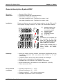
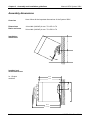
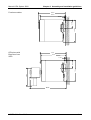
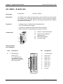
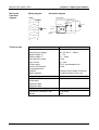
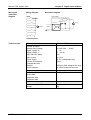
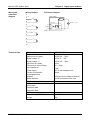
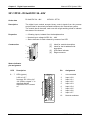
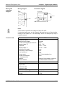
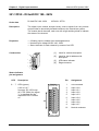
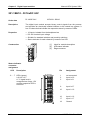
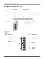
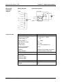
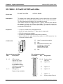
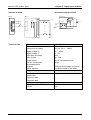
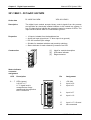
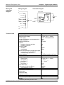
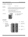
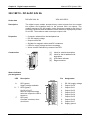
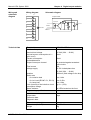
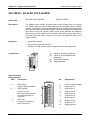
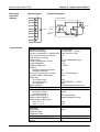
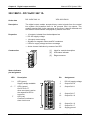
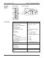
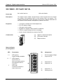
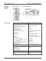
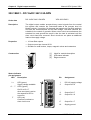
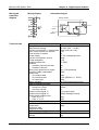
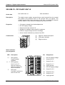
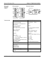
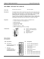
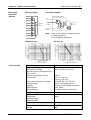
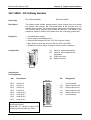
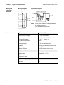
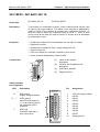
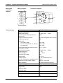
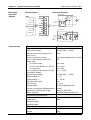
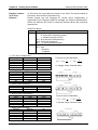
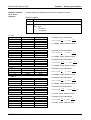
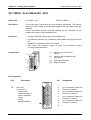
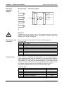
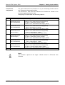
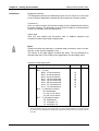
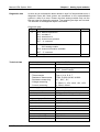
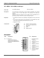
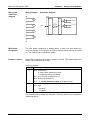
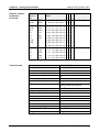
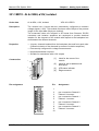
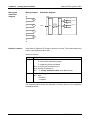
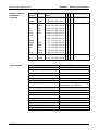
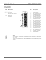
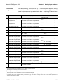
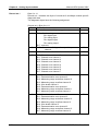
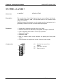
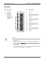
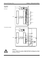
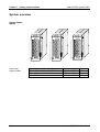
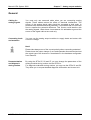
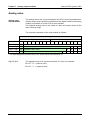
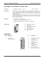
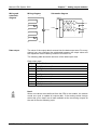
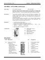
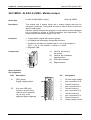
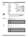
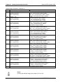
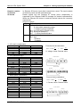
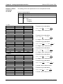
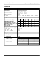
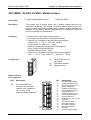
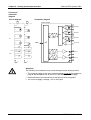
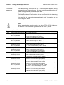
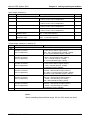
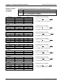
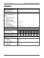
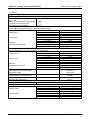
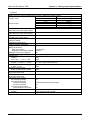
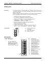
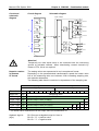
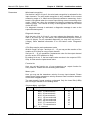
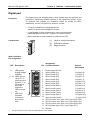
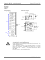
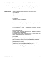
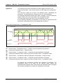
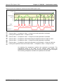
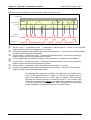
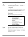
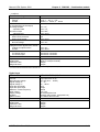
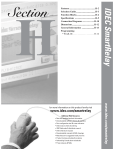
Chapter 3 Digital input modules
Manual VIPA System 200V
221-1BH10 - DI 16xDC 24V
Order data
DI 16xDC 24V
Description
The digital input module accepts binary control signals from the process
and provides an electrically isolated interface to the central bus system. It
has 16 channels that indicate the respective status by means of LEDs.
Properties
•
•
•
•
Construction
VIPA 221-1BH10
16 inputs, isolated from the backplane bus
DC 24V nominal input voltage
Suitable for standard switches and proximity switches
Status indicator for each channel by means of an LED
[1]
[2]
[3]
1
Label for module description
LED status indicator
Edge connector
2
3
Status indicator
connector
assignment
LED
.0 ... .7
Description
LEDs (green)
I+0.0 to I+0.7
A "1" signal level is
recognized as of app. 15V
and the respective LED is
turned on
Pin
DI 16xDC24V
n
.0
.1
.2
.3
.4
.5
.6
.7
.0
.1
.2
.3
.4
.5
.6
.7
n+1
VIPA 221-1BH10
3-30
1
2
3
4
5
6
7
8
9
10
11
12
13
14
15
16
17
18
X 2
3 4
Assignment
1
2
3
not connected
Input I+0.0
Input I+0.1
.
.
.
.
.
.
9
10
Input I+0.7
Input I+1.0
.
.
.
.
.
.
16
17
18
Input I+1.6
Input I+1.7
Ground
HB97E - SM - Rev. 09/19