1
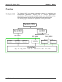
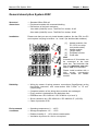
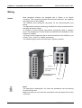
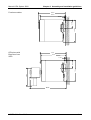
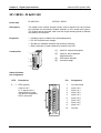
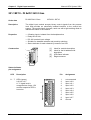
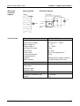
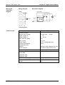
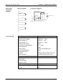
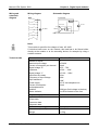
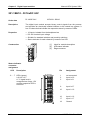
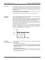
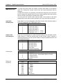
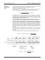
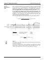
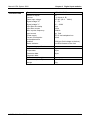
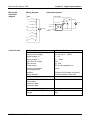
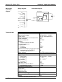
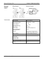
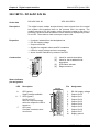
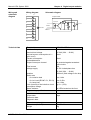
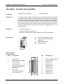
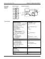
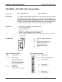
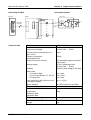
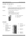
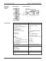
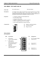
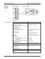
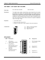
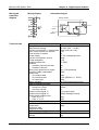
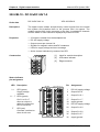
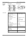
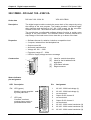
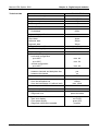
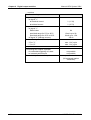
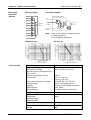
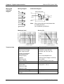
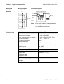
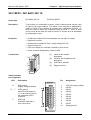
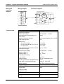
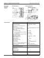
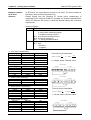
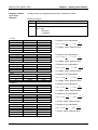
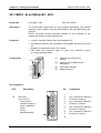
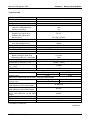
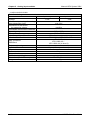
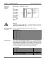
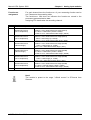
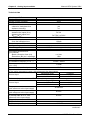
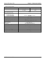
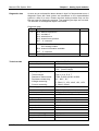
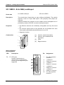
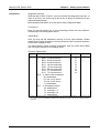
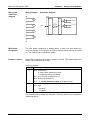
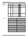
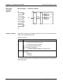
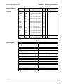
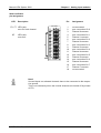
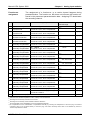
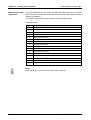
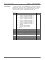
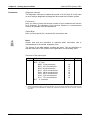
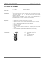
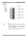
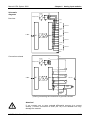
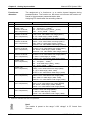
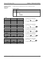
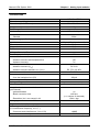
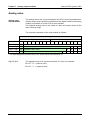
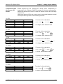
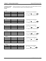
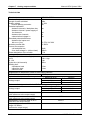
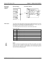
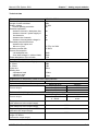
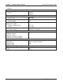
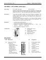
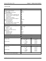
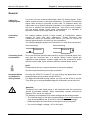
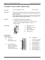
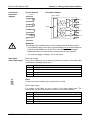
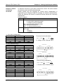
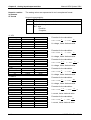
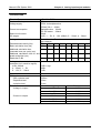
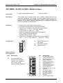
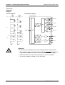
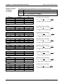
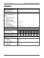
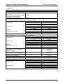
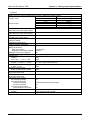
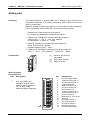
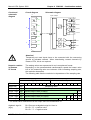
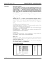
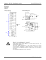
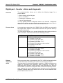
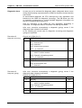
Chapter 5 Digital input/output modules
Wiring and
schematic
diagram
Wiring diagram
Manual VIPA System 200V
Schematic diagram
L+
1
Input output module
2
Optocoupler
3
4
5
DC 24V
6
V-Bus
Minternal
LED
DC 24V
Optocoupler
7
8
9
Minternal
10
Technical data
5-4
M
Electrical data
Number of channels
Rated load voltage
No-load current consumption at L+
(all A.x=off)
Output current per channel
Total output current
Switch rate
- for resistive load
- for ind. load (IEC947-5-1, DC13)
- for lamp load
Limit (internal) of the inductive circuit
interruption voltage
Nominal input voltage
Signal voltage "0"
Signal voltage "1"
Input filter time delay
Input current
Voltage supply
Current consumption (backplane bus)
Data width in the process image
Status indicator
Programming specifications
Input data
Output data
Parameter data
Diagnostic data
Dimensions and weight
Dimensions (WxHxD) in mm
Weight
VIPA 223-1BF00
8
DC 24V (20.4 ... 28.8V)
50mA
1A protected against short circuits
12A
max. 1kHz
max. 0.5Hz
max. 10Hz
typ. L+ (-52V)
DC 24V (20.4 ... 28.8V)
0 ... 5V
15 ... 28.8V
3ms
typ. 7mA
DC 5V via backplane bus
65mA
1byte PII, 1byte PIQ
via LEDs located on the front
1byte
1byte
25.4x76x88
50g
HB97E - SM - Rev. 09/19