1
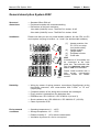
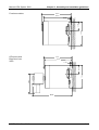
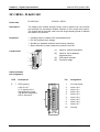
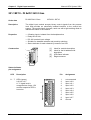
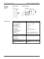
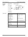
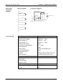
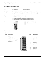
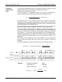
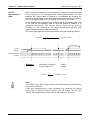
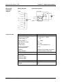
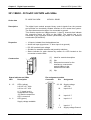
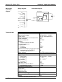
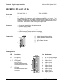
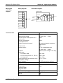
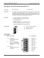
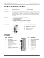
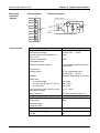
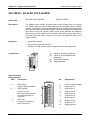
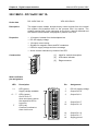
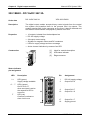
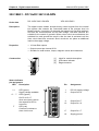
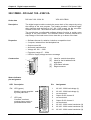
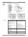
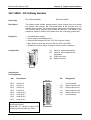
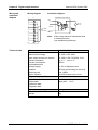
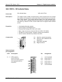
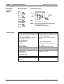
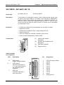
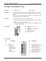
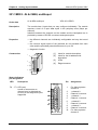
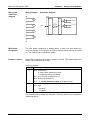
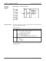
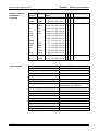
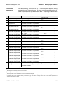
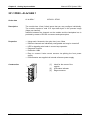
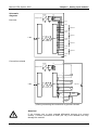
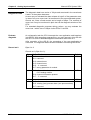
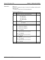
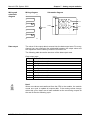
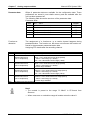
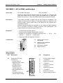
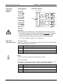
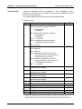
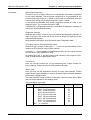
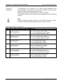
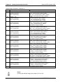
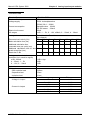
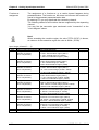
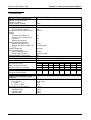
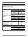
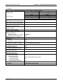
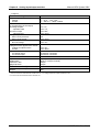
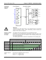
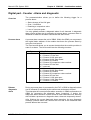
Chapter 6 Analog input modules
Manual VIPA System 200V
231-1BD52 - AI 4x16Bit, multiinput
Order data
AI 4x16Bit multiinput
VIPA 231-1BD52
Description
The module has got 4 inputs that you may configure individually. The
module requires a total of 8 input data bytes in the process image (2byte
per channel).
Isolation between the channels on the module and the backplane bus is
provided by means of DC/DC converters and optocouplers.
Properties
• the different channels are individually configurable and may be turned
off
• the common signal inputs of the channels are not isolated from each
other and the permitted potential difference is up to 5V
• LED for cable break and over current in sensor circuits
• diagnostic function
1
[1]
[2]
2
[3]
[4]
Construction
Label for module description
Label for the bit address with
description
LED status indicator
Edge connector
3
4
Status indicators
pin assignment
LED
Description
Pin
Assignment
SM 231
AI 4x16Bit
F0 ... F3 LED (red):
turned on when an open circuit
exists on the 4...20mA sensor
circuits
1
1
F0
3
F1
blinks when the current > 40mA
at all current sensor circuits
2
4
5
F2
6
7
F3
8
9
I0
X 2
3 4
VIPA 231-1BD52
6-16
2
3
4
5
6
7
8
9
10
For 4wire systems
channel 0
+ channel 0
Channel 0 common
+ channel 1
Channel 1 common
+ channel 2
Channel 2 common
+ channel 3
Channel 3 common
For 4wire systems
channel 2
HB97E - SM - Rev. 09/19