1
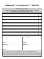
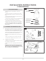
Traditional Range Cooker
Oil Versions
Instructions for Use,
Installation and Servicing
For use in GB, IE (Great Britain and Eire)
This appliance has been certified for use in countries other than those stated. To install this appliance in these countries,
it is essential to obtain the translated instructions and in some cases the appliance will require modification. Contact Redfyre for further information.
IMPORTANT
The front and top of this cooker will become hot whilst in operation, it is therefore recommended that a suitable guard should be
used for the protection of young children, the elderly or infirm.
Please read these Instructions carefully before installation or use.
Keep them in a safe place for future reference and when servicing the cooker.
The commissioning sheet on the third page should be completed by the Installer.
C601918 Issue 11 (September 2010)
CONTENTS
COVERING THE FOLLOWING MODELS
COLOUR
00 = Cream
04 = Green
02 = Blue
10 = Pewter
HOB LIDS 1 = Chrome Square
FOUR OVEN 0 = None
HOB STYLE 2 = LPG
03 = Black
12 = Claret
3 = Chrome Round
1 = Natural Gas
3 = Electric
C R E
ELECTRIC ELEMENT 0 = No 1 = BOOST ELEMENT
2 = ELECTRIC OVENS
HOT WATER BOILER
0 = None
NUMBER OF OVENS
2 = 2 Oven
2 = 90 ltr
5 = 135ltr
4 = 4 Oven
FUEL TYPE 5 = Oil
Appliance Commissioning Checklist
Dealer and Installer Information
3
3
USER INSTRUCTIONS
4
Description
General
Lighting the Burner
Cooker Temperature Control
Turning the Burner off
Care of the Cooker
Vitreous Enamel Finish
Cleaning the Hotplates
Cleaning the Ovens
Running In
Servicing
Ventilation
Instruction Details
Hot Surfaces
Clearances to Hot Surfaces
After Sales Service Information
4
4
4
5
5
6
6
6
6
6
6
6
7
7
7
7
COOKING GUIDE
8
Cooking with your Redfyre Traditional
Secrets to Using the Traditional
Four Oven Traditional
Two Oven Traditional
Hotplates
Gas Hob
Electric Hob
Aluminium Plate
8
9
9
9
9
10
10
10
Technical Specification
Four Oven Dimensions
Two Oven Dimensions
SITE REQUIREMENTS
13
Flue Systems
Flue Height
Horizontal Runs
Flue Cleaning
13
13
13
13
INSTALLATION INSTRUCTIONS
Wind Pressure on Buildings
Terminations
Recommended Flue Positions - Roof
Terminal Positions
Oil Supply
Oil Supply Line Diagram
Boiler Connections
Ventilation
Appliance Location
INSTALLATION
Appliance Location
Health and Safety
Electrical Connection
Two Oven and Four Oven Models
Setting/Adjusting Door Latch Pins
CD10 Form
Electrical Wiring Diagram
Commissioning
11
12
12
2
20
20
20
20
20
21
21
22
23
The Sleeve Burner
Checking the Burner Oil Level
Checking Oil Flow Rates
Burner Levelling
Lighting to Check Smoke & Flue
Electrical Tests
SERVICING INSTRUCTIONS
26
Replacing Parts
Oil Burner
Flue Ways
Oil Valve
Cooker Check
Recommissioning
Boost Element
Hob
Boost Element
Fault Finding
Spare Parts List
Service Records
26
27
27
27
27
27
27
27
27
29
32
33
11
14
14
15
16
17
18
19
19
19
23
23
24
24
24
24
APPLIANCE COMMISSIONING CHECKLIST
IMPORTaNT NOTICE
Explain the operation of the appliance to the end user, hand the completed instructions to them for safe keeping,
as the information will be required when making any guaranteed claims.
FLUE CHECK
1.
Flue is correct for appliance
2.
Flue flow test
3.
Spillage test
4.
Chimney flue draught reading
Pass
Fail
MM
WG
OIL CHECK
1.
Are all joints and connections airtight
2.
Oil depth in the burner base
3.
Check KBB operation
4
CD10 AND CD 11 completed and returned
MM
ELECTRICAL CHECK
1.
Earth bond continuity
2.
Insulation resistance check
3.
Electrical insulation flash test
DEALER AND INSTALLER INFORMATION
Dealer . . . . . . . . . . . . . . . . . . . . . . . . . . . . . . . . . . . . . . . . . . . . . . . . . . . . . . . . . . . . . . . . . . . . . Installation Company . . . . . . . . . . . . . . . . . . . . . . . . . . . . . . . . . . . . . . . . . . . . . . . . .
. . . . . . . . . . . . . . . . . . . . . . . . . . . . . . . . . . . . . . . . . . . . . . . . . . . . . . . . . . . . . . . . . . . . . . . . . . . . . . . ................................................................................
. . . . . . . . . . . . . . . . . . . . . . . . . . . . . . . . . . . . . . . . . . . . . . . . . . . . . . . . . . . . . . . . . . . . . . . . . . . . . . . Engineer . . . . . . . . . . . . . . . . . . . . . . . . . . . . . . . . . . . . . . . . . . . . . . . . . . . . . . . . . . . . . . . . . . . Contact No.. . . . . . . . . . . . . . . . . . . . . . . . . . . . . . . . . . . . . . . . . . . . . . . . . . . . . . . . . . . . . . Contact No.. . . . . . . . . . . . . . . . . . . . . . . . . . . . . . . . . . . . . . . . . . . . . . . . . . . . . . . . . . . . . . . Date of Purchase. . . . . . . . . . . . . . . . . . . . . . . . . . . . . . . . . . . . . . . . . . . . . . . . . . . . . . . OFTEC Reg No.. . . . . . . . . . . . . . . . . . . . . . . . . . . . . . . . . . . . . . . . . . . . . . . . . . . . . . . . . . Model No.. . . . . . . . . . . . . . . . . . . . . . . . . . . . . . . . . . . . . . . . . . . . . . . . . . . . . . . . . . . . . . . . Date of Installation . . . . . . . . . . . . . . . . . . . . . . . . . . . . . . . . . . . . . . . . . . . . . . . . . . . . Serial No.. . . . . . . . . . . . . . . . . . . . . . . . . . . . . . . . . . . . . . . . . . . . . . . . . . . . . . . . . . . . . . . . . Fuel Type. . . . . . . . . . . . . . . . . . . . . . . . . . . . . . . . . . . . . . . . . . . . . . . . . . . . . . . . . . . . . . . . . This product is guaranteed for 2 years from the date of installation, as set out in the terms and conditions of sale between
REDFYRE COOKERS and your local REDFYRE dealer. This guarantee will be invalid, to the extent permitted by law, if the above
Appliance Commissioning Checklist is not fully completed by the installer and available for inspection by a REDFYRE engineer. The
guarantee will only be valid during the second year, to the extent permitted by law, if the annual service recommended in the Instructions
for Use has been completed by a Oftec registered engineer, and a copy of the service visit report is available for inspection by a REDFYRE
engineer.
3
USER INSTRUCTIONS
Congratulations, you are now the proud owner of a new
Redfyre Traditional Cooker. As manufacturers we are proud
of the features and quality of construction of all our
cookers.
2.8
2.9 DO NOT spray aerosols in the vicinity of this appliance
while it is operating.
2.10 DO NOT COVER THE FLUE OUTLET AT THE REAR OF
THE TOP SURFACE.
1. DESCRIPTION
1.1
1.2
DO NOT place combustible materials onto the hotplate
surfaces even when the cooker is off.
The Redfyre Traditional Range cooker is a heat-store cooker
using a single burner powered by oil. The heat from this
burner is built up and stored in the massive cast iron
components of the cooker interior. This stored heat is
transferred to each of the four ovens and the two hot plates
to provide the unique cooking qualities of a range cooker.
The heat-store cooking process is ideal for winter warmth
and conventional cooking practices..
2.11 Do not use unstable saucepans and always position handles
away from the edge of the hotplate.
3. LIGHTING THE BURNER
Both the Two Oven and Four Oven versions of the cooker
have an electric boost element in the roof of the bottom
right oven to convert it to a second roasting oven. You
might, for example, choose to roast by gas while also baking
with electric.
UNDER NO CIRCUMSTANCES ATTEMPT TO LIGHT A
HOT BURNER
3.1
The controls can be found at the left-hand side of the
cooker on the oil control valve. This may have been
mounted within a cupboard. See diagram 1.
• Turn ON the oil supply at the Isolation Valve
1.3
The Traditional requires an efficient chimney.
1.4
The Two-Oven model can also include a small boiler for
domestic hot water (DHW).
• Lift the control knob slightly and turn to maximum
setting, 6.
• Allow 15 minutes for oil to enter and stabilise in the
burner base, Diagram 1
1.5
Both models are controlled heat storage cookers; the main
burner adjusts heat according to demand.
1
2. GENERAL
2.1
As manufactures and suppliers of cookers and heating
products we take care to ensure these products meet all
safety requirements when properly used and installed. To
this end, our products are thoroughly examined and tested
before delivery.
2.2
This appliance must be installed in accordance with the
rules in force and only used in a sufficiently ventilated
space.
2.3
A qualified installer must install and service this appliance.
In the UK this person must be OFTEC registered.
Lever
2.4 No alterations to the cooker should be carried out
whatsoever. Do not adjust any sealed components because
this may affect both the performance of the appliance and
your own safety.
2.5
A cooker that is incorrectly installed, altered in any way or
not serviced can invalidate approval of the appliance, its
warranty and may affect your statutory rights.
2.6
Do not allow clothes, furnishings or any combustible
material to come into contact with any flue pipe.
2.7
The outside cooker surface is coated with vitreous enamel.
Take care not to accidentally scratch this surface with
cooking utensils or when sliding utensils across. Use suitable
products to clean this surface. DO NOT use oven cleaners
or cleaners containing citric acid.
4
USER INSTRUCTIONS
• Remove the two screws retaining the front cover,
Diagram 2
2
3.2
Immediately after lighting, turn the oil control valve knob to
setting 1, see Diagram 1.
3.3
After about 30 minutes, increase the oil flow rate by turning
the oil control knob to setting 4. To reduce heat-up time,
turn to setting 6 for approximately 3 hours and then turn
down to the recommended setting.
3.4
After 1 hour, check that the burner is glowing red showing
it is running correctly. If there are yellow/orange flames
present, then turn the cooker off and call an approved
engineer.
4. cooker temperature control
AR1601
4.1
The temperature control knob is found on the top of the oil
control valve. Turning the control knob anti clockwise will
increase the cooker temperature, Diagram 1.
4.2
Heat to the cooker can be reduced by turning the control
knob down or increased by turning up from the
recommended setting. The recommended setting is 3 for a
Two-Oven and 4 for a Four-Oven model. However, if
adjusted it will take 3 to 4 hours to stabilise temperature
due to the thermal mass of the cooker.
4.3
The temperature indicator is located above the top oven
door and has three sections: black, silver and red.
4.4
After approximately 8 hours the cooker should have
reached it's optimum operating temperature. The column of
mercury should be approximately mid way between the red
and black areas on the temperature gauge. This will indicate
that the cooker has been saturated with heat. To achieve an
accurate temperature value, this can be accomplished by
employing an oven thermometer and recording the reading
as a datum in relation to the position of the column of
mercury.
• Open control door and remove the two wing nuts of the
burner access door, Diagram 3
3
AR1321
• Open the lighting port cover located at the front of the
burner shell, Diagram 4
4
5. turning the burner off
• Turn the control knob clockwise to the OFF position,
Diagram 1
• Turn the oil supply OFF at the Isolation Valve
Frost Protection (DHW version only):
5.1
If the DHW boiler is to be out of use for a long period of
time during severe weather conditions, it is recommended
that the whole system be drained down to avoid the risk of
freezing. Frequent draining, especially in hard water areas,
should be avoided as this may lead to scale build up inside
the boiler.
5.2
For short periods of absence, leave the cooker operating at
a low thermostat setting.
AR1323
• Insert a suitable taper or lighter through the lighting port
to light the wick, taking care not to disturb the shells,
Diagram 4
IT IS THEN IMPORTANT TO CLOSE THE LIGHTING
PORT COVER and replace the burner access door, ensuring
it is correctly located and sealed.
5
USER INSTRUCTIONS
• ALWAYS try to wipe up spillages when they happen
You will get better results if you clean the cooker when it is
cool, see 6.3.
6.1
Use hot soapy water and a cloth to clean the front and
finish with a soft dry cloth to avoid streaking.
6.2
We recommend you switch off the cooker at the mains and
let it cool before cleaning or carrying out any maintenance
work.
The chart in Section 9 suggests cleaning methods.
Top Plate
Oven
Oven Door
Coloured Parts
A vitreous enamel finishes the surround of hotplates on
some models and coats the front, doors and top plate.
Burnt-on food should be removed carefully using a plastic
kitchen scrubber. DO NOT USE wire wool as this can
damage the enamel finish.
7.2
The side panels of Redfyre cookers are finished in stove
enamel.
• Clean with a damp cloth only
Doors can be lifted off their hinges to clean. DO NOT
immerse the whole door in water because this will affect
the insulation in the door.
Redfyre parts
appropriate cleaning
methods
7. vitreous enamel finish
7.1
9.3
V.E.D.C. cleaners
• NEVER use caustic, citric or abrasive cleaning products
on your cooker because these scratch and damage its
surface
• ALWAYS follow the grain of the stainless steel when
scrubbing
Nylon Brush
Cream cleaner
IMPORTANT
• Use wire wool and soapy water to clean the stainless
steel surround at the front of the oven when it is cool
Wire Brush
Hot water & soap
6. care of the cooker
Vitreous Enamel
Surround
Hot Plates ✓
✓ ✓ ✓ ✓
✓
✓
✓
Internal Shelves ✓ ✓ ✓
✓ ✓
✓
Internal Seal ✓
✓ ✓
✓
Front Sides Doors Chrome Handles Towel Rail
Top Plate Hotplate Lids ✓
✓
✓
✓
✓
✓ ✓
✓
✓
✓
✓
✓
8. cleaning the hotplates
10. running in
• Use a wooden handled wire brush to clean the hotplates.
Care must be taken not to scratch the enamel surround
where applicable. Steel top plates can be cleaned with wire
wool and soapy water.
• ALWAYS follow the grain of the stainless steel
8.1
The inside of each hotplate lid can be cleaned using wire
wool and soapy water while following the grain of the
stainless steel.
10.1 The new surface coating on your Redfyre cooker “burns off”
to create a harmless odour during its first hours of use. The
smell disappears after a short period but if it persists ask
your installer for advice.
11. servicing
9. cleaning the ovens
9.1
11.1 The cooker must be serviced every 6 months by a qualified
OFTEC registered engineer. In all correspondence, always
quote the model and serial number found on the data
badge.
The cast iron interior reduces any spills inside the oven to
powder over a period of time. You need only brush out the
oven when dirty.
• Clean racks and linings when cool
9.2
Wire brush any stubborn carbon stains and vacuum or
brush away the deposits. The wire brush may scratch the
interior surface of the oven but does no harm. Because the
oven surface is natural you must prevent oxidation by
drying all surfaces thoroughly after cleaning.
11.2 You must turn off your cooker 12 hours before servicing.
Your cooker cannot be serviced while it is hot.
6
USER INSTRUCTIONS
12. ventilation
12.1 Heat and moisture are produced by oil range cookers.
• Ensure the kitchen is well ventilated
Below is a step by step guide to reporting a fault with your
appliance.
What to do in the event of an appliance fault or
breakdown:
Step 1: Always contact your installer or commissioning engineer in
the first instance. He must thoroughly check all his work
PRIOR to requesting a service visit from Redfyre.
12.2 You may need to open a window or increase mechanical
ventilation during prolonged use of the cooker.
12.3 Air for combustion is taken in through the cooker’s burner
door.
Step 2: If your appliance has developed a fault during the
guarantee period, your installer should contact the Redfyre
Service Centre for assistance.
• DO NOT shut off or block this door or any additional air
vents fitted by your installer in any compartment or to the
outside
What happens if my installer/engineer is unavailable?
Step 3:Contact Redfyre direct. We will provide you with the name
and telephone number of our Service Agent. However, a
charge may apply if the fault is not covered by the
appliance guarantee (payment will be requested on site by
our independent Service Agent).
12.4 Any purpose-provided ventilation should be periodically
checked to ensure that it is free from obstruction.
12.5 If a gas hob is installed in the four-oven version, then 30
cm2 (4.5”2) of extra ventilation is required.
A charge will be made where:
• Our Field Service Engineer finds no fault with the
appliance.
• The cause of a breakdown is due to other parts of the
plumbing/heating system or is caused by equipment not
supplied by Redfyre.
• Where the appliance falls outside the 2 year guarantee
period (See terms and conditions enclosed).
• The appliance has not been correctly installed,
commissioned or serviced as recommended. (See
Commissioning, Installation and Servicing instructions).
14.1 Protect children and the infirm from the hot surfaces of this
cooker by providing a suitable guard. All parts of the cooker
should be regarded as a working surface with the exception
of the hob and door handles.
• The breakdown occurs immediately following an annual
service visit. In this instance, your appointed Service Agent
must check all his work PRIOR to requesting Redfyre to
attend.
14.2 Parts of the cooker become very hot (e.g. hot plates and
ovens) when in use and remain hot for a long period after
use. Take great care when using the cooker and use oven
gloves whenever appropriate.
PLEASE NOTE:
Unauthorised invoices for attendance and repair work
carried out on this appliance by any third party will not be
accepted by Redfyre.
Every enamelled part on your cooker is unique and has its
own individual characteristics. Coloured parts may differ
slightly in shading. This will not impair performance in any
way and is quite normal.
IMPORTANT CUSTOMER NOTICE
Cosmetic damage, stains and scratches produced by
cooking and cleaning are NOT covered by the statutory
guarantee.
13. instruction details
13.1 The Commissioning sheet at the front of this book must be
completed by your installer to help with any future
correspondence. This records the essential installation
details. In all correspondence you must quote the model
and serial number.
14. hot surfaces
15. Clearances to hot surfaces
15.1 Clearance to the side of the appliance must be at least 10mm
15.2 The shelf height above hot plate must be at least 800mm.
15.3 Ensure a clearance of 25mm is kept around the flue pipe.
16. AFTER SALES SERVICE INFORMATION
We provide a 2 year warranty and a nationwide network of
Service Engineers
We also provide qualified FIELD SERVICE ENGINEERS who
are available to attend a breakdown or manufacturing fault
occurring whilst the appliance is under guarantee.
7
USER INSTRUCTIONS
COOKING GUIDE
1. COOKING WITH YOUR REDFYRE
TRADITIONAL
1.1
Cooking with the Redfyre Traditional is really quite simple.
The cooker is designed to run at a constant temperature.
You should only need to increase the temperature for a
large amount of cooking:
•
The left-hand hotplate is for rapid boiling
•
The right-hand hotplate is for simmering or slow boiling
•
The top right oven is used for roasting and hot baking
1.2
For recipes which require a hot oven, use the top part of
the oven. For a moderate oven heat, use the lower part
with the heat shield over the top. When the shield is not
being used, it is best stored outside the cooker.
1.3
The bottom oven is for baking or simmering depending on
the model type:
•
Four Oven model - baking
•
Two Oven model - simmering and plate warming
The temperature of this bottom oven can be increased by
using the electric boost thermostat for baking or for
additional roasting:
• Turn the thermostat to the required setting. An amber neon indicator remains lit until the desired temperature is reached.
5
AR1601
The booster produces radiant heat, so if cooking over long
periods, cover your dish to protect it from this heat.
When the main cooker is switched off, you can use the
electric element in this bottom oven. The oven heats and
cools slower than a conventional oven because of the heavy
gauge materials of its components.
OVEN CONTENTS
1 x C610334 - Roasting Tin
1 x C610335 - Roasting Tin Trivet
1 x C600566 - Baking Shelf
8
USER INSTRUCTIONS
COOKING GUIDE
2. SECRETS OF USING THE TRADITIONAL
2.1
Choose the right position in the cooker for your dish: high,
moderate or low temperature, fast or slow cooking.
Different areas of the Traditional are kept at different
temperatures.
2.2
The temperature of each oven varies and within each oven
it varies from top to bottom and side to side. Get to know
your ovens and where to position shelves. Then cook your
dish to perfection.
2.3
The left-hand hotplate is the hottest and is used for fast
boiling. The right-hand one is for simmering. A large
stainless steel cooking surface surrounds these hotplates
over which pans can be spread.
When not in use, the lids should be closed to conserve heat
inside the cooker. When you plan a lot of cooking, you will
find it more efficient to cook in the ovens rather than on
the top hotplates. Many dishes can be started on the
hotplates and transferred to the appropriate oven.
TOP LEFT SIMMERING OVEN
3.8
Grid shelf in middle position – a tray of meringues will cook
on this shelf in 11/2 to 2 hours. Also rich fruit cakes can be
left here for 4 – 11 hours depending on the size, producing
a deliciously moist cake.
3.9
Floor of the oven - Casseroles and stock can be cooked
overnight after first simmering on the hotplates for 10
minutes. Cooked food can be kept warm without spoiling
or gently reheated. Fruit for jam and marmalade can be
cooked here over a long period. Gently melt chocolate and
butter in a bowl in this oven. Root vegetables can be boiled
for 5 minutes, drained, covered and placed here for 45-60
minutes without spoiling. Sautéed onions can be started on
the simmering plate, covered and placed in the simmering
oven for 15 minutes.
BOTTOM LEFT WARMING OVEN
3.10 This is the ideal place to keep serving dishes and plates
warm and rest cooked meat, store sauces and keep covered
meals warm.
4. TWO-OVEN TRADITIONAL
3. FOUR-OVEN TRADITIONAL
TOP RIGHT ROASTING OVEN
In this hot oven, position shelves on runners as follows:
3.1
Top Shelf - used to grill meats, vegetables etc., or brown
dishes such as gratins under heat radiating from the roof.
3.2
Second Shelf down – used for roasting potatoes, cooking
scones etc. Covered dishes and hot puddings can be quickly
reheated here.
3.3
Middle Shelf – used for roasting meats, jacket potatoes,
pastry, bread rolls, loaves and pizzas.
3.4
Grid Shelf on oven floor – used for large loaves of bread
and slower roasts (e.g. pork, poultry).
3.5
Direct onto oven floor – for pastry, tarts and pies or crisping
up the bottom of bread loaves. The frying pan can be
heated on the floor before transferring to the hotplates.
Frying can be completed on the oven floor to avoid greasy
spills around the hotplates.
BOTTOM RIGHT BAKING OVEN
3.6
Use the moderate heat of this oven for baking cakes and
biscuits and cooking fish. Slow, long-cooking dishes are
often started on one of the hotplates, then transferred to the
appropriate place in this oven.
3.7
TOP RIGHT ROASTING OVEN
This functions in the same way as the Four Oven model.
See 3.1 to 3.5.
BOTTOM RIGHT SIMMERING OVEN
4.1
The gentle heat of this oven is used for slow, long cooking.
Dishes are often started on one of the hotplates and
transferred to this oven. Casseroles brought to the boil on
the hot plate can slow simmer to perfection in this oven.
Fruit cakes can be cooked for a long time, depending on
size, from 3 – 11 hours.
4.2 Grid shelf on the floor – Stews and casseroles can be
cooked here taking 3 - 4 hours or you can start the
casserole on the floor of the roasting oven for 30 minutes
and transfer to the simmering oven to reduce time. Bring
vegetables to the boil on the hotplate, drain, cover with a
lid and steam. Melt chocolate and butter in a bowl. Cooked
meat can be kept warm without spoiling.
A Boost Element also provides this oven with extra radiant
heat.
9
4.3
Directly on the floor – Stock pots can cook overnight after
being started on the simmering plate as well as pâtés
cooked in a bain-marie and meringues cooked on the oven
floor. Prepared jam fruit can be softened slowly in their pot
here.
4.4
A Boost Element converts the bottom right to a second
Baking/Roasting oven.
USER INSTRUCTIONS
COOKING GUIDE
This Hob has four radiant electric hobs with the following power
ratings:
5. HOTPLATES
LEFT-HAND BOILING PLATE
5.1
The fairly fierce heat of this hotplate rapidly boils or browns
dishes. Consider heating a frying/browning pan on the floor
of the roasting oven to conserve heat before placing
ingredients and oil/butter in the pan on this plate.
RIGHT-HAND SIMMERING PLATE
5.2
This plate is for gentle browning, simmering and slow
boiling of vegetables, (especially green vegetables), starting
or re-heating casseroles, sauces, soups or milk. This
simmering plate can also be lightly greased and used like a
griddle.
left-back, 1800W
left front, 1200W
right-back, 1200W
right-front, 1500W
Each control has a setting from 0 to 10 giving you a wide
field of adjustment from slow melting through to fast
boiling.
REFER to Care of the Cooker for advice on cleaning the Hob
surface.
ALUMINIUM PLATE
8
6. GAS HOB
6
AR2073
An optional aluminium plate can be fitted instead of the gas or
electric hob to act as a warming plate.
AR2071
The Gas has four burners:
•
•
•
• •
1 x 3,00kW Rapid burner
2 x 1.75kW Semi-rapid burners
1 x 1.00kW Auxiliary burner
Front controls
Under knob auto-ignition
7. ELECTRIC HOB
7
AR2072
10
INSTALLATION INSTRUCTIONS
TECHNICAL SPECIFICATION
BURNER SPECIFICATION
6” DON, NATURAL DRAUGHT VAPORIZING TYPE
APPLIANCE TYPE/FUEL
OIL FIRED: KEROSENE TO BS2869 CLASS C2 (28 SECOND)
COUNTRY OF ORIGIN
UNITED KINGDOM
OIL FLOW RATES
MIN = 4 cc/MINUTE
MAX = 8cc/MINUTE
OIL CONTROL VALVE
TOBY DVR5
FLUE DRAUGHT
MIN 0.02”WG – 0.50 mm WG
MAX 0.04” WG – 1.00 mm WG
HEAT INPUT
5 kW MAXIMUM
HEAT OUTPUT
90 BOILER = 1.2 kW
TO WATER
135 BOILER = 1.6 kW
(DHW MODELS ONLY)
BOILER CONNECTIONS
28 mmø COMPRESSION
OIL CONNECTIONS
10 mmø COMPRESSION
FLUE OUTLET
102 mmø
WEIGHT
2 OVEN = 410kg max
4 OVEN = 585 kg max
ELECTRICAL SUPPLY 230V 50 HZ
BOOST ELEMENT
1.25 Kw 7a
BOOST ELEMENT + ELECTRIC HOB
7.05 kW30A
11
INSTALLATION INSTRUCTIONS
TECHNICAL SPECIFICATION
1
SHELF HEIGHT
Note: There is an optional plinth which increases all heights by 75mm.
AR1562
2
SHELF HEIGHT
Note: There is an optional plinth which increases all heights by 75mm.
12
AR2008
INSTALLATION INSTRUCTIONS
SITE REQUIREMENTS
1. GENERAL
1.1
1.2
1.3
These instructions relate to all oil fired Two and Four Oven
Traditional cookers with a conventional flue. These include
models with and without a hot water boiler.
The Two and Four Oven Traditional are normally delivered
in kit form for assembly on site by an engineer trained by
Redfyre Cookers. Please refer to the Build Instructions
which are supplied separately.
One very important point to note with the oil fired
models is that the oil control valve is fitted on the lefthand side of the cooker. When fitting the cooker, extra
clearance is required for the control valve. (See
dimensions diagrams for all clearances).
•
The flue is continuous. Any breaks in seals, flue liners etc.
must be rectified. A flexible steel liner (oil grade), BS4543
Parts 1 & 3 is highly recommended.
•
The flue diameter is uniform over its entire length.
•
The flue is not serving another appliance. Never connect to
a shared flue.
•
The flue is not constructed wholly of a single-skin pipe. This
must not be used under any circumstances. It has minimal
heat retention properties, and will lead to an overall loss of
efficiency, as well as condensation in the flue and ovens.
•
Vermiculite backfill, or the equivalent, is used whenever a
flexible liner is installed. It must be sealed top and bottom.
Salt-glazed clay or precast liners are acceptable.
2. flue systems
3. flue height
1
3.1
A minimum of 3 metres (10 feet) is required between the
cowl and the top of the cooker. This ensures that the flue
gases are vented into relatively still air, and is less affected
by nearby buildings or trees in certain circumstances, trees
or other obstructions may need to be removed.
3.2
Installation with flues in excess of 10 metres in height is not
recommended. Very tall flues are likely to exceed the
maximum flue draught specified in the technical data. High
flue draughts can cause problems with oven and hob
temperatures and increase running costs.
3.3
The cowl must be at least 1 metre above any obstruction
within 600mm, and the siting of the flue should comply
with OFTEC regulations.
4. horizontal runs
NOTE: The first section of flue from the draught divert to the
sealing plate must be 102mmø (4”),
2.1
2.2
This appliance is designed to operate with a Class 2 flue,
nominally 125mm (5”) in diameter. To ensure correct
performance, both flue and termination should conform to
the relevant British Standards.
NOTE: COMBUSTION TESTING, FLUE GAS ANALYSIS
AND DRAUGHT MEASUREMENT MUST BE CARRIED
OUT ON SITE BY THE APPROVED COMMISSIONING
ENGINEER.
4.1
Horizontal runs of greater than 450mm (18”) should be
avoided. If the flue has to be offset, the recommended
angle is 60o. and the legal minimum 45o. Never use a bend
of 90o.
4.2
If the installation is using an existing flue, horizontal runs
should be avoided. A vertical rise of 600mm (24”) is the
mandatory minimum before turning into the flue. If it is
necessary to exhaust into an extended flue after the
mandatory 600mm rise, the horizontal run must not exceed
450mm.
NOTE: ALL FLUE CONNECTIONS MUST BE FULLY
SEALED AND INSPECTED BY THE INSTALLER ON
COMPLETION.
The quality of the flue is vital for satisfactory operation. A
thorough pre-installation check by a flue specialist is
advisable. If an existing flue is to be used, the specialist will
advise on re-lining and the correct choice of cowl or
terminal for site wind conditions etc.
2.3
Before installing the appliance into an existing flue, check
that:
•
The flue is clear of obstructions. Repair any structural
damage.
5. flue cleaning
5.1
13
Annual inspection and cleaning of the flue is recommended.
Therefore a cleaning door, or some other means of access,
should be incorporated into the system.
INSTALLATION INSTRUCTIONS
SITE REQUIREMENTS
6. wind pressure on buildings
6.1
Flues should not be terminated in a high pressure area.
7. teRminations
7.1
The most appropriate cowl depends entirely on conditions at
the site. Several may have to be tried before one is found
that gives good all-year performance. In some circumstances
it may not be possible to entirely exclude down draughts
caused by surrounding buildings or trees, so fit an anti-down
draught cowl, preferably of the OH type. A ‘Chinaman’s Hat’
is not sufficient and a GC 1 type cowl must not be fitted.
OH Ltd. Telephone Number 01223 291222
MIN EFFECTIVE HEIGHT = 3M
2
Anti-down
draught cowl
Cement mortar
Plate clamp
Back fill with
Vermiculite insulation
or similar
Bends must be no less than
135o
Vitreous enamelled steel or
stainless steel with cleaning
cover
Brick chimney
Stainless steel
flexible flue
liner
Seal liner into
flue socket with
fire cement
MIN RISE BEFORE
BEND = 600mm
Conventional brick chimney with liner
AR1580
14
INSTALLATION INSTRUCTIONS
SITE REQUIREMENTS
3
AR1570
15
INSTALLATION INSTRUCTIONS
SITE REQUIREMENTS
4
16
INSTALLATION INSTRUCTIONS
SITE REQUIREMENTS
8. OIL SUPPLY
8.9
The tank should be fitted with fill and vent connections
(weather protected), a drain-off cock, shut-off valve and an
oil level indicator.
PLASTIC TANKS
OIL
8.1
The oil burner is factory set to burn CLASS C2 kerosene to
BS2869.
8.10 Polythene tanks are now widely used because of their
advantages over traditional steel tanks:
OIL STORAGE TANKS
8.2
Size and Location of Tank in accordance with OFTEC
regulations.
– They do not need pier supports and can be mounted
directly on any flat surface giving uniform support for the
tank base.
The tank should be large enough to allow for economic
deliveries and be located in the most unobtrusive position,
having regard to the need for safety, filling, maintenance (if
steel tank) and head of oil required.
– They do not corrode and therefore never need painting.
– They are easier to handle because of their lower weight.
– They have a 10 year manufacturer’s guarantee.
Plastic tanks should be fitted with similar components to
those used with steel tanks.
OIL SUPPLY LINE (see diagram 5)
8.3
8.4
Whist it is highly unlikely that a fire could start from an oil
tank, it does need to be protected from a fire that may
originate in a nearby building. For this reason, the tank
should not be located nearer than 1.8 metres from a
building, nor closer than 760mm from a site boundary.
Where a tank has to be less than 1.8 metres, the building
wall must not have any openings other than small ventilation
openings. The wall shall have a 30 minute resistance to an
internal fire and extend 1.8 metres from any part of the
tank.
8.11 A maximum head of 3.2 metres should be exceeded –
35kpa pressure. The oil shut-off valve should be fitted as
close to the burner as practical to enable the burner to be
disconnected without undue loss of oil. A 5-10 micron oil
filter must be fitted (preferably close to the tank in an
accessible position). The filter must be connected in the oil
supply pipe and positioned externally.
Alternatively, a non-combustible radiation barrier must be
provided which meets the requirements of BS5410. This
standard applies to tanks up to a capacity of 3,400 litres.
FIRE PROTECTION – PART J
8.5
Where a storage tank is close to a dwelling, fire cladding
must be provided to the eaves if less than 1.8m from the
top of the tank
8.6
The cladding must extend 300mm beyond the tank
8.7
The tank must be sited on a non-combustible base.
J6 – PROTECTION AGAINST POLLUTION
A tank must be bunded if:-
– Less than 10 metres from “controlled water” such as a
stream, ditch, river, lake, pond, canal or coastal water.
– Less than 50 metres from a well, spring or drinking water.
– The tank cannot be viewed from the delivery point.
– There is a risk of oil reaching a manhole cover or drain.
– If the capacity exceeds 2500 litres.
– Sited over hard ground or hard surfaced ground that could
allow spilled oil to enter “controlled water”.
STEEL TANKS
8.8
Steel tanks should comply with the requirements of BS799,
Pt 5, 1987 and mounted on brick or block piers with a
waterproof membrane between the piers and tank.
8.12 All oil line joints must be completely sealed and the total
pipe run thoroughly flushed out before connecting to the
burner. No soldered joints are permitted in the oil line.
FIRE VALVE
8.13 A remote acting 60°C fire valve must be fitted in the oil line
outside the building with its sensing phial positioned
adjacent to the oil control valve.
8.14 An additional 90°C fire valve must be fitted near to the
cooker on the incoming oil line with its sensing phial
positioned within the cooker. Clips are provided for
retaining the phial.
17
INSTALLATION INSTRUCTIONS
SITE REQUIREMENTS
3.2m
5
18
INSTALLATION INSTRUCTIONS
SITE REQUIREMENTS
11.2 Kitchen units can be fitted, allowing 10mm clearance either
side of the cooker and taking into account access to the oil
connection. If a pine or similar wood surface is used, take
care the wood is well seasoned and protected from the side
of the cooker to prevent drying out or splitting.
9. BOILER CONNECTIONS - 2-OVEN
model
9.1
(Domestic hot water models). The flow and return pipes
from the cooker are 28mm and an INDIRECT water
cylinder should be located not more than 5.5 metres from
the cooker. No radiators should be fitted unless exceptional
circumstances when the cylinder is very close to the cooker.
In such cases, it may be advisable to run a heat leak
radiator or a heated towel rail. The entire system is to be
operated by an open vented gravity circulation only.
9.2
Pipe work should be in accordance with the relevant
recommendations given in BS6700.
9.3
It is recommended on the Two Oven 90 model that an
indirect 190 litre (40 gallon) hot water storage cylinder of
the double feed complying with BS1566 Pt 1:DF Type 10
be fitted. This should be lagged and fixed vertically as near
as possible to the cooker.
11.3 You need to allow at least a 3mm gap between the kitchen
surfaces, cupboards or walls for expansion and services.
6
9.4 For a Two Oven 135 model an indirect 280 litre (60 gallon)
hot water storage cylinder of double feed type complying
with BS 1566 Pt 1:DF Type 12 should be fitted. This should
be lagged and fixed vertically as near as possible to the
cooker.
10mm
9.5 A drain tap(s) must be located in accessible positions which
permit the draining of the appliances and hot water storage
vessel. Drain at the lowest point(s). Taps should be at least
1/2” BSP to BS 2879.
10. VENTILATION
10.1 Combustion appliances shall be so installed that there is an
adequate supply of air to them for combustion and for the
efficient working of any flue pipe or chimney. See detailed
recommendations in Building Regulation J.
10.2 The required minimum effective area of a permanent air
vent in the outside wall in the room in which the cooker is
installed is 550mm2 for all models with or without DHW
options.
This size may need to be increased depending on
conditions, for example, if an extractor fan exists.
11. APPLIANCE LOCATION
11.1
It is important that the cooker is situated on a flat surface of
non-combustible material and must be capable of
supporting the total weight of the cooker. If a plinth is
required, the recommended size to correspond to standard
work top is 650mm x 950mm for the Two Oven models
and 650mm x 1450mm for the Four Oven models. The
height may be varied depending upon the height of the
user or work top. A purpose made adjustable plinth is
available as an optional extra.
19
NOTE: If the Oil Control Valve is mounted on the Left
Hand side of the cooker it will be necessary to increase this
clearance to a minimum of 10mm.
INSTALLATION INSTRUCTIONS
INSTALLATION
2.8 Avoid, as far as possible, any skin contact with mineral oil or
with clothing contaminated with mineral oil.
1. IMPORTANT
1.1
This appliance should be installed according to regulations
in force and only used in a well-ventilated space. Read
these instructions before installing or operating.
2.9 Never breath any mineral oil vapours. Do not fire the
Burner in the open i.e. outside of the Cooker as a misfire
will cause neat oil vapours.
1.2
The person(s) who installs this appliance, commissions,
services and carries out remedial work (e.g. electrical fault
finding), must have suitable engineering qualifications.
2.10 Barrier cream containing lanolin is highly recommended
together with a strict routine of personal cleaning.
1.3
The Redfyre Traditional must be installed by a competent
person and this person must be an OFTEC trained and
registered engineer.
1.4
The Traditional is supplied in kit form to be assembled on
site.
1.5
2.11 Under no circumstances should mineral oils be taken
internally.
3. ELECTRICAL CONNECTIONS
There is a Manual detailing how to assemble the cookers
correctly which forms part of these Installation Instructions.
Engineers carrying out the assembly must be trained by
Redfyre Cookers. This is only supplied to officially trained
engineers. Please contact Redfyre Cookers for further
details.
ELECTRICAL WARNING
THIS APPLIANCE IS SUPPLIED IN COMPONENT AND
SUB-ASSEMBLY FORM. WHILE THE SUB ASSEMBLIES
THEMSELVES HAVE BEEN TESTED FOR ELECTRICAL
SAFETY AT REDFYRE, IT IS ESSENTIAL THAT THE WHOLE
APPLIANCE IS TESTED WHEN IT IS FULLED ASSEMBLED.
THIS WORK CAN ONLY BE UNDERTAKEN BY A SUITABLY
QUALIFIED ELECTRICIAN TRAINED IN THE USE OF
SPECIALIST EQUIPMENT. THE TEST MUST INCLUDE:
• EARTH BOND CONTINUITY
• INSULATION RESISTANCE CHECK
• ELECTRICAL INSULATION FLASH TEST
2. HEALTH AND SAFETY
2.1
2.2
2.3
Redfyre takes every reasonable care to ensure products are
designed and constructed to meet all general safety
requirements when properly used and installed. This
standard means products are comprehensively tested and
examined before despatch.
IF THERE IS NO MAINS SUPPLY OR THE ABOVE TESTS
CANNOT BE CARRIED OUT, ENSURE THAT A WARNING
LABEL IS ATTACHED TO THE APPLIANCE STATING THAT IT
SHOULD NOT BE USED UNTIL ELECTRICALLY TESTED BY A
SUITABLY QUALIFIED ELECTRICIAN AND INFORM THE
CUSTOMER.
Glass rope, mineral wool, insulation pads, ceramic fibre,
glass insulation, can be harmful if inhaled, irritating skin,
eyes, nose or throat. On handling, avoid inhalation and
contact with eyes by using disposable gloves, face masks
and eye protection. When disposing, reduce dust with
water spray and ensure parts are securely wrapped. Wash
hands and other exposed parts after handling. When
disposing, reduce dust with water spray and ensure parts
are securely wrapped.
4. TWO & FOUR OVEN MODELS
This appliance is heavy and care must be taken when
installing.
WIRING EXTERNAL TO THE APPLIANCE MUST BE IN
ACCORDANCE WITH THE CURRENT IEE WIRING
REGULATIONS, ELECTRICITY AT WORK REGULATIONS
AND ANY LOCAL REGULATIONS.
Boost Element Only
KEROSENE & GAS OIL FUELS (MINERAL OILS)
4.1
The appliance is supplied for 230v – 50 Hz. Total power
consumption is 1.25 kW. Fuse rating is 5A External.
4.2
The method of connection to the mains supply MUST
facilitate complete electrical isolation of the appliance. This
can be achieved by plugging into a socket without switch.
4.3
Should the plug on the flexible cord not be the type for
your socket outlets, do not use any adapter, but remove the
plug from the cord and discard. Carefully prepare the end
of the supply cord and fit a suitable plug.
2.4
The glues, sealants and paints of this product present no
known hazards if used in the manner anticipated.
2.5
IMPORTANT
Note the points and items listed under 2.3, 2.4 and 2.5. It
is the Engineer’s responsibility to ensure protective clothing
or equipment is worn for personal health and safety when
handling hazardous materials.
2.6 The effect of mineral oils on the skin vary according to the
duration of exposure. The lighter fractions also remove the
protective grease normally present on the surface of the skin
rendering the skin dry, liable to cracking and more prone to
damage caused by cuts and abrasions.
2.7 Skin rashes (oil acne). Seek immediate medical attention for
any rash, wart or sore developing on any part of the body.
20
INSTALLATION INSTRUCTIONS
INSTALLATION
WARNING: THIS APPLIANCE MUST BE EARTHED
IMPORTANT
The wires in this mains lead are coloured in accordance
with the following code:
- green/yellow
Earth
- blue
Neutral
- brown
Live
4.4
Should the mains lead of the appliance ever require
replacing, we recommend that the operation is carried out
by a qualified electrician, who will replace it with a lead of
the same size and temperature rating.
Four-oven model:
Boost Element and Electric Hob, or Boost Element and
Electric Ovens
4.5
3. Adjust door latch pin, until the door seal seats securely and
evenly around the front plate. The door latch pin can only
be adjusted with the door in the open position. Close the
door to check the seal.
4. Tighten the flange nut to ensure that the door latch pin is
locked in position.
NOTE: NOW COMPLETE THE COMMISSIONING
CHECKLIST AS DESCRIBED BELOW - AND MAKE SURE
THE USER IS FAMILIAR WITH BOTH THE OPERATION
OF THE APPLIANCE, AND THE SAFETY MEASURES.
It is a requirement under OFTEC regulations that the
commissioning is recorded on a CD11 form, available
from Oftec. Once completed, a copy is to be given to the
end user and one copy sent to Redfyre. Failure to do so
may invalidate the guarantee.
The appliance must be connected by a competent person
using fixed wiring via a DOUBLE POLE SWITCHED 30 amp
OUTLET with a minimum contact clearance of 3mm.
WARNING: THIS APPLIANCE MUST BE EARTHED
IMPORTANT
CD10 FORM
The wires in this mains lead are coloured in accordance
with the following code:
- green/yellow
Earth
It is a requirement under OFTEC regulations that the
installation is recorded on a CD10 form (a copy is attached
at the end of this manual). Once completed, a copy is to be
given to the end user and one copy sent to Redfyre. Failure
to do so may invalidate the guarantee.
Complete this form now.
- blue
All tests are to be conducted under the rules in force
following best practice procedures. In the UK these are the
procedures laid down by OFTEC.
Neutral
9. SETTING/ADJUSTING DOOR LATCH PINS
Door latches on the Traditional require setting when the
cooker is assembled.
Setting:
1.
Loosen locking flange nut and remove door latch pin, nut
and black washer.
2. Apply ‘Loctite’ to door pin and re-assemble door latch pin,
washer and flange nut, but do not tighten flange nut.
3. Fit door.
4. Adjust door latch pin, until the door seal seats securely and
evenly around the front plate. The door latch pin can only
be adjusted with the door in the open position. Close the
door to check the seal.
5. Tighten the flange nut to ensure that the door latch pin is
locked in position.
Door Adjustment
1. Open door.
2. Loosen locking flange nut.
21
INSTALLATION INSTRUCTIONS
INSTALLATION
1
WIRING DIAGRAM FOR TRADITIONAL 2 & 4-OVEN COOKER
AR1563
22
INSTALLATION INSTRUCTIONS
commissioning
1
1. THE SLEEVE BURNER
• Ensure the oil level control bracket is level in all
directions
• Adjust the oil level line on the body of the oil control
valve to approximately 225mm (8?”) from the base of the
cooker
• Open the control door and remove inner burner door
held in position by two wing nuts
• Disconnect the compression elbow and withdraw the oil
burner base assembly and place on a flat surface
• Disassemble the burner and fit the oil burner base
assembly into the cooker and reconnect the oil feed pipe.
• Adjust the front support levelling screws of the burner
base so that the BURNER IS LEVEL IN ALL DIRECTIONS.
SEE SECTION 4.
TOP LID
SET OF SHELLS
VAPORIZING PLUG
BURNER WICKS
BURNER BASE
2. CHECKING THE BURNER OIL LEVEL
2.1
If the oil level is too shallow raise the oil to compensate.
After adjustment allow 15-20 minutes for the oil to settle to
it’s new depth. Then measure the depth and wait a further
10 minutes to ensure it has stabilised and measure again.
• Turn on the oil supply, it may be necessary to purge the
oil line of air, remove the burner shells and wicks
• Lift the control knob slightly and turn to the maximum
setting, 6
• Allow 10-15 minutes for oil to enter the burner base
• Check that the oil depth in the burner base is 5mm.
2.2
To adjust to the correct depth:
• Adjust the oil control valve height via the three levelling
screws and the mounting bracket
• Refit the burner wicks, vaporising lid, burner shells and
top lid.
IMPORTANT: ENSURE THE SHELLS ARE SEATED WITH
AN AIRTIGHT SEAL AGAINST THE BURNER BASE AND
THE CUT-OUTS IN THE BURNER WICKS LINE UP WITH
THE OIL CHANNELS IN THE BURNER BASE.
2
3
High flame
adjustment
screw
23
Low flame
adjustment screw
INSTALLATION INSTRUCTIONS
commissioning
stablise. Check the oil depth, this should be between 5mm
and 6mm. Correct if necessary by adjusting the height of
the Oil Control Valve as in 4.3 above.
3. CHECKING OIL FLOW RATES
NOTE: THE OIL CONTROL VALVE IS FACTORY SET.
THIS ONLY NEEDS TO BE CHECKED OR ADJUSTED IF IT
IS SUSPECTED THAT THE BURNER IS USING TOO
MUCH OIL
• Turn the Oil Control Valve OFF by turning the Control
Knob fully clockwise
• Disconnect the oil feed pipe after the oil control valve at
the compression elbow and place a suitable calibrated
measuring vessel under the outlet port of the oil control
valve
• Lift the oil control knob slightly and turn to the maximum
setting 6 for approximately two minutes to establish oil flow
• Turn the oil control knob to the setting 1 to check the
LOW FIRE SETTING, this should be 4.0cc/min.
ALLOW AT LEAST 10 MINUTES FOR OIL FLOW RATE TO
STABILISE BEFORE CHECKING. If adjustment is necessary,
this can be altered by turning the Low Fire adjustment
screw 11 clockwise to decrease and anti-clockwise to
increase the flow rate.
• Turn the oil control knob to maximum to check the
HIGH FIRE SETTING, this should be 8.0 cc/min.
ALLOW AT LEAST 10 MINUTES FOR OIL RATE TO
STABILISE BEFORE CHECKING. If adjustment is necessary,
this can be altered by turning the High Fire adjustment
screw 8 clockwise to decrease and anti-clockwise to
increase the flow rate.
• Allow a two minute period in between screw adjustments
for the oil rate to stabilise
• Reconnect oil feed pipe work
NOTE: AVOID KINKING IN THE OIL FEED PIPE; IT
CAUSES AIR LOCKS. ALWAYS RUN THE PIPE TO A LOW
POINT, THEN PROVIDE A GRADUAL UPWARD SLOPE
TO THE BURNER.
Open the Burner Door and remove the Burner Cover
4.2
Remove the Burner Lid, Burner Shells, Vapour Chamber
Lids and Wicks
4.3
4.4
4.6
Replace the Vapour Chamber Lid. Make sure that both
surfaces are clean and free from damage. Place the Lid in
position and rotate applying hand pressure; remove the Lid
and check that a complete witness mark is evident, then
replace the Lid.
NOTE: UNDER NO CIRCUMSTANCES MUST ANY
SEALANT (FIRE CEMENT OR SILICON) BE USED. THE
WEIGHT OF THE VAPOUR CHAMBER LID ITSELF IS
SUFFICIENT TO EFFECT A SATISFACTORY SEAL.
4.7
Replace the Burner Shells ensuring that they locate on their
respective spigots. The seams of the Shells should be
orientated at 90º to one another to prevent a local
starvation of air.
4.8
Replace the Burner Lid.
5.1
After checking the high and low oil flow rates:
• Turn the control knob to the maximum setting, 6
• Lift the lighting port cover located at the front of the
burner shell
• Insert a suitable taper through the lighting port to light
the wick. It is then important to close the lighting port
cover.
5.2
Immediately after lighting:
• Turn the oil control valve to its lowest setting, 1
• Replace the burner access door. It is important that the
door is correctly located and sealed
• Close the outer control door
SMOKE TEST
4. BURNER LEVELLING
4.1
Replace the wicks ensuring that the cut outs are arranged in
line with radial ports facing downwards.
5. LIGHTING TO CHECK SMOKE & FLUE
Care must be taken when adjusting flow rates. The adjusting
screw should only be turned a quarter of a turn at a time.
Allow the control to stabilise between adjustments then
re-measure the rate.
4.5
Place a Cross Test Level on the Burner Base, adjust the
levelling studs until the base is level in all directions. Tighten
the lock nuts on the levelling studs and recheck for level.
5.3
Wait half an hour before carrying out a smoke test:
• Drill a hole in the flue pipe to accept a smoke pump
probe. (This hole will require plugging after testing)
• Sample the fume products through the hole using a
Barrach smoke pump where all readings should indicate a
smoke number 0-1 at low and high fire
• Set the control knob to setting 3 for a Two Oven cooker
and setting 4 for a Four Oven cooker
FLUE DRAUGHT
NOTE: ALL NATURAL DRAUGHT BURNERS DEPEND FOR
EFFICIENT OPERATION ON REASONABLE FLUE
CONDITIONS.
Turn the Oil Control Knob to maximum and allow oil to
enter the Burner Base. Allow 15 minutes for the oil to
24
INSTALLATION INSTRUCTIONS
COMMISSIONING
THE FLUE DRAUGHT MUST BE NO LESS THAN 0.02’’WG
AND NOT MORE THAN 0.04’’WG (0.5mm TO 1.0mm). IF
EXCESSIVE FLUE DRAUGHT IS PRESENT, THEN A
STABILISER SHOULD BE FITTED IN THE FLUE SYSTEM.
8. ELECTRICAL TESTS
Electrical warning
THIS APPLIANCE IS SUPPLIED IN COMPONENT AND
SUB- ASSEMBLY FORM. WHILST THE SUB-ASSEMBLIES
THEMSELVES HAVE BEEN TESTED FOR ELECTRICAL
SAFETY AT REDFYRE, IT IS ESSENTIAL THAT THE WHOLE
APPLIANCE IS TESTED WHEN IT IS FULLY ASSEMBLED.
THIS WORK CAN ONLY BE UNDERTAKEN BY A
SUITABLY QUALIFIED ELECTRICIAN TRAINED IN THE
USE OF SPECIALISED EQUIPMENT. THE TEST MUST
INCLUDE;
– EARTH BOND CONTINUITY
– INSULATION RESISTANCE CHECK
– ELECTRICAL INSULATION FLASH TEST
IMPORTANT
IF THERE IS NO MAINS SUPPLY OR THE ABOVE TESTS
CANNOT BE CARRIED OUT, ENSURE THAT A WARNING
LABEL IS ATTACHED TO THE APPLIANCE STATING
THAT IT SHOULD NOT BE USED UNTIL ELECTRICALLY
TESTED BY A SUITABLY QUALIFIED ELECTRICIAN AND
INFORM THE CUSTOMER.
25
SERVICING INSTRUCTIONS
REPLACING PARTS
IMPORTANT
It is essential that range cookers are serviced and flue ways inspected and cleaned at regular 6 month intervals.
The work must be carried out by trained service engineers.
The appliance should be turned off at least 12 hours before the arrival of the engineer to allow it to cool.
1. general
3
1.1
All major components can be replaced from the front of the
cooker.
• Make sure both electrical and oil supplies are isolated
before carrying out any service work
2. oil burner
2.1
Behind the control door:
• Remove the two screws retaining the front cover,
Diagram 1
AR1321
• Place a suitable container under the oil feed pipe elbow
and undo the compression joint, Diagram 4
1
4
AR1601
AR1321
• Remove the two wing nuts retaining the burner door,
Diagram 2
2
• Lift out the burner assembly and dismantle all the
components, Diagram 5
5
AR1321
• Remove the KBB phial from the two clips on the lower
panel and remove the two screws to allow access to the oil
feed pipe, Diagram 3
26
• Remove all the carbon deposits from the burner base, oil
ways and feed pipe
• Gently brush any carbon deposits from the shells and top
lid. Also clean the vaporising plug
• Check the wick and replace if necessary
• Reassemble in reverse order
SERVICING INSTRUCTIONS
REPLACING PARTS
ENSURE THE WICKS ARE ASSEMBLED WITH THE
CUTOUTS AT THE BOTTOM EDGE NEAREST THE
BURNER BASE TO ALIGN WITH THE OIL WAYS. THE
VAPORISING PLUG MUST BE FITTED CORRECTLY AND
THE SHELLS SEATED TO THE BURNER BASE WITH AN
AIR TIGHT SEAL. THE LIGHTING PORT MUST BE
FACING FORWARD.
• FINALLY FIT THE LID
NOTE: IF THE COOKER IS BEING SERVICED AS A
WHOLE, DO NOT FIT THE BURNER UNTIL THE FLUE
WAYS HAVE BEEN CLEANED.
• Clean the Inlet Valve Tip and its mating seat
• Reassemble the components carefully
• Turn on the oil supply and allow the valve to fill
• Check for leaks
5. cooker check
3. flue ways
• Remove the burner as described in Section 2
• Remove the three screws on each of the hotplates. • Lift out both plates. These are very heavy.
• Remove the “D” baffle from the barrel noting its orientation
• Clean all the flue ways with a suitable brush
• Reassemble in reverse order and ensure the fins on the boiling plate run parallel with the cooker
• Check all seals
• Check the top and bottom oven vents are not blocked
• Check the door seals are sound
• Check the hotplate lid seals are sound and seated
correctly
6. recommissionINg
• Ensure the burner has been correctly assembled, Section
2
• Check and adjust flue pull if necessary
• Instruct the user for continued safe operation and to
maintain the guarantee the appliance must be serviced
every six months
• Demonstrate the correct operation of the appliance and
ensure the customer has a copy of the user instructions
• Advise the customer that under no circumstances attempt
to light a hot burner
4. oil valve
• Turn off the Oil Supply at the tank
• Turn off the isolation valve at the control
• Remove the Draining Screw from the Oil Control and
drain the oil from the Control
7.1
The boost oven element is situated in the lower right-hand
oven. To remove the element:
• Remove the two pan head screws securing the valve
cover plate
Lift the cover from the Control Knob end. Note the position
of the arm attached to the Lid. It rests on the metering
system.
• Undo the two screws holding the support bracket,
Diagram 6, Arrow A
• Remove the two pan head screws securing the filter
compartment cover flange
• Remove the nylon filter element
• Replace the drain screw ensuring it seals on it's sealing
washer
Carefully clean the slot of the metering stem with a non
metallic instrument. It is of paramount importance that the
size of this slot is not increased. If the slot has been enlarged
this will automatically increase the size of the flow of fuel.
The stem should be cleaned with kerosene. Avoid hand
contact with the area adjacent to the slot as oils on the skin
can partially or wholly block the slot.
7. BOOSTING ELEMENT
6
A
A
B
• Remove the pan head screw and carefully lift out the
Inlet Valve and Float assembly
27
AR1560
• Remove the single fixing screw holding the element and
carefully pull it forward, Diagram 6, Arrow B.
• Remove the two wires and replace the element
• Reassemble in reverse order
SERVICING INSTRUCTIONS
REPLACING PARTS
9. boost element thermostat
8. HOBS
8.1
WARMING PLATE:
• Remove the four fixing screws and lift the plate from its
recess
• Pull the control knob off the spindle.
• Remove the four screws retaining the front panel,
Diagram 8, Arrow B.
8
NOTE: WHEN REPLACING THE GAS AND ELECTRIC HOBS,
CLEAN THE EDGES OF BOTH THE COOKER TOP AND
THE HOBS PRIOR TO APPLYING THE SEALANT.1
8.2
GAS HOB:
• Isolate the gas supply to the hob
From inside the top-left oven:
• Remove the six screws securing the access plate, Diagram
7
AR1601
7
• Remove the two screws securing the control to the panel,
Diagram 9
9
retaining nut
AR1590
• Undo the gas connection at the loose joint through the
access panel in the top of the oven
In the top oven is a large retaining nut that secures the hob:
• Remove the nut and washer, Diagram 7
Using a sharp knife:
• Cut the seal around the edges of the hob
• Lift the front off the hob and draw it forward
approximately 150mm to gain access to the rear of the
ovens
8.3
ELECTRIC HOB:
To remove the electric hob, using a sharp knife:
• Cut the seal around the edges of the hob
• Lift the front off the hob and draw it forward
approximately 150mm to gain access to the rear of the
ovens
AR1591
Note the positions of all the wires and disconnect the
control. Alternatively, transfer each wire to the new
control individually.
• Remove the two screws holding the oil valve cover,
Diagram 10, Arrow A.
10
28
B
B
B
B
A
A
AR1601
• Remove the phial from the bracket in the top of the oven
• Pull the capillary through the access tube. The thermostat
can now be removed.
• Reverse the order of the above procedure to reassemble.
SERVICING INSTRUCTIONS
FAULT FINDING
EVIDENCE OF FAULT
CAUSE
Trip/Reset lever operates repeatedly
1. Oil level in control too high.
2. Top of tank over 10 feet above oil control unit.
Yellow flame on high fire only
1. High fire screw set too high
2. Burner out of level
Yellow flame on low fire only
1. Low fire screw set too low
2. Burner out of level
Yellow flame at all Control Knob positions
1.
2.
3.
4.
5.
Yellow flame at one point of burner only
1. Wicks incorrectly positioned or upside down
2. Vaporizing Chamber Lid not fully seated
3. Shells not correctly seated
4. Lighting flap not correctly seated
5. Burner out of level
Flame funneling at centre of burner
1. Wicks incorrectly position or upside down
Flame appears to leave top of burner
1. Too little primary air
2. Too low a flue pull
3. Flue partly or fully blocked
Burner popping
1. Too little primary air
2. Too much secondary air
3. Too low a flue pull
4. Down draught in flue. Fit suitable anti down draught cowl
5. Wicks incorrectly positioned or upside down
6. Oil depth in burner base too deep
7. Vaporizing Chamber Lid not fully seated
Burner surging
1. Variations in flue draught. Fit suitable stabilizer
2. Fuel inlet overheating. Insulate with fireproof material
3. Oil depth in burner base too deep
Impossible to set high fire high enough
1. Too little primary air
2. Flue partly or fully blocked
29
Too much primary air
Too little secondary air
Vaporizing Chamber Lid not fully seated
Shells not correctly seated
Burner out of level
SERVICING INSTRUCTIONS
FAULT FINDING
EVIDENCE OF FAULT
CAUSE
Impossible to set high fire low enough
1. Too much primary air
Impossible to set low fire high enough
1. Too little primary air
Impossible to set low fire low enough
1. Too much primary air
Oil smell apparent
1. Too little primary air
2. Too low a flue pull
3. Down draught in the flue. Fit suitable anti-down draught cowl
4. Flue partly or fully blocked
5. High fire screw set too high
Black stain around any door
1. Too little primary air
2. Too low a flue pull
3. Down draught in the flue. Fit suitable anti-down draught cowl
4. Flue partly or fully blocked
5. High fire screw set too high
Burner carbons up after short period
1. Low fire screw set too low
2. Oil Control filter blocked. Remove and clean with boiling water
and dry thoroughly before replacing
3. Incorrect or contaminated fuel. A small amount of contamination
can cause trouble. Clean out tank and refill with a new fuel
Unable to light burner
1. Control metering stem slot obstructed. To clear, turn Control
Knob from OFF to full ON several times
2. Oil Control Filer blocked. Remove and clean with boiling water
and dry thoroughly before replacing.
3. Metering stem in oil control sticking. Replace control
4. Fuel inlet blocked. Service.
5. Oil depth in burner base too shallow.
6. Oil level in tank too low
7. Air lock in oil line tank - burner - control
8. Incorrect or contaminated fuel. A small amount of contamination
can cause trouble. Clean out tank and refill with a new fuel
9. Isolation valve at tank shut
10. Oil Control valve flooded and Inlet Valve closed
30
SERVICING INSTRUCTIONS
FAULT FINDING
EVIDENCE OF FAULT
CAUSE
Burner goes out after burning 1-2 hours
1. Too little primary air
2. Down draught in the flue. Fit suitable anti-down draught cowl
3. Low fire screw set too low
4. Control metering stem slot obstructed. To clean, turn Control
Knob OFF to full ON several times
5. Fuel inlet blocked. Service
6. Oil depth in burner base too shallow
7. Oil level in tank too low
8. Air lock in oil line tank - burner - control
9. Incorrect or contaminated fuel. A small amount of contamination
can cause trouble. Clean out tank and refill with a new fuel.
10. Oil Control valve flooded and Inlet Valve closed
Burner goes out for no apparent reason
1. Too little primary air
2. Down draught in flue. Fit suitable anti-down draught cowl
3. Flue partly or fully blocked
4. Low fire screw set too low
5. Control metering stem slot obstructed. To clear, turn Control
Knob from OFF to full ON several times
6. Trip lever operated
7. Oil Control Filer blocked. Remove and clean with boiling water
and dry thoroughly before replacing.
8. Fuel inlet blocked. Service.
9. Oil level in tank too low.
10. Air lock in oil line tank - burner - control
11. Incorrect or contaminated fuel. A small amount of contamination can cause trouble. Clean out tank and refill with a new fuel
12. Oil Control valve flooded and Inlet Valve closed
Burner soots up
1. Too little primary air
2. Too low a flue pull
3. Down draught in flue. Fit suitable anti-down draught cowl
4. Vaporizing Chamber Lid not fully seated
5. Shells not correctly seated
6. Incorrect or contaminated fuel. A small amount of contamination can cause trouble. Clean out tank and refill with a new fuel.
COOKERS
Not reaching required temperature
1. Too little primary air
2. Too high a flue pull
3. Flue partly or fully blocked
4. High fire screw set too low
Overheating
1. Too low a flue pull
2. Low fire screw set too high
Variations in temperature
1. Variations in flue draught. Fit suitable stabilizer.
31
SERVICING INSTRUCTIONS
SPARE PARTS
22. spare parts
SPARES
NUMBER
SETS OF WICKS
601356
BUNDY TUBE
99628
BURNER ASSEMBLY
600812
ELBOW
99629
NIPPLE
600838
THERMOMETER TUBE
600795
TEMPERATURE SCALE
601029
TOP INFILL PLATE
601485
OIL CONTROL VALVE
600884
CONTROL VALVE COVER (BLACK)
600443
90o TEDDINGTON FIRE VALVE
600846
BOOST OVEN ELEMENT
600822
BOOST ELEMENT THERMOSTAT - FOUR OVEN VERSION
EL0310
BOOST ELEMENT THERMOSTAT - TWO OVEN VERSION
EL0307
OPTIONAL EXTRAS
PLINTH - (TWO OVEN)
C6005
PLINTH - (FOUR OVEN)
C6006
32
SERVICE RECORDS
1st Service
Date of Service:. . . . . . . . . . . . . . . . . . . . . . . . . . . . . . . . . Next Service due:. . . . . . . . . . . . . . . . . . . . . . . . . . . . . . . . Signed:. . . . . . . . . . . . . . . . . . . . . . . . . . . . . . . . . . . . . . . . Dealer’s Stamp
2nd Service
Date of Service:. . . . . . . . . . . . . . . . . . . . . . . . . . . . . . . . . Next Service due: . . . . . . . . . . . . . . . . . . . . . . . . . . . . . . . Signed: . . . . . . . . . . . . . . . . . . . . . . . . . . . . . . . . . . . . . . . Dealer’s Stamp
3rd Service
Date of Service:. . . . . . . . . . . . . . . . . . . . . . . . . . . . . . . . . Next Service due:. . . . . . . . . . . . . . . . . . . . . . . . . . . . . . . . Signed:. . . . . . . . . . . . . . . . . . . . . . . . . . . . . . . . . . . . . . . . Dealer’s Stamp
4th Service
Date of Service:. . . . . . . . . . . . . . . . . . . . . . . . . . . . . . . . . Next Service due: . . . . . . . . . . . . . . . . . . . . . . . . . . . . . . . Signed: . . . . . . . . . . . . . . . . . . . . . . . . . . . . . . . . . . . . . . . Dealer’s Stamp
5th Service
Date of Service:. . . . . . . . . . . . . . . . . . . . . . . . . . . . . . . . . Next Service due:. . . . . . . . . . . . . . . . . . . . . . . . . . . . . . . . Signed:. . . . . . . . . . . . . . . . . . . . . . . . . . . . . . . . . . . . . . . . Dealer’s Stamp
6th Service
Date of Service:. . . . . . . . . . . . . . . . . . . . . . . . . . . . . . . . . Next Service due: . . . . . . . . . . . . . . . . . . . . . . . . . . . . . . . Signed: . . . . . . . . . . . . . . . . . . . . . . . . . . . . . . . . . . . . . . . Dealer’s Stamp
7th Service
Date of Service:. . . . . . . . . . . . . . . . . . . . . . . . . . . . . . . . . Next Service due:. . . . . . . . . . . . . . . . . . . . . . . . . . . . . . . . Signed:. . . . . . . . . . . . . . . . . . . . . . . . . . . . . . . . . . . . . . . . Dealer’s Stamp
8th Service
Date of Service:. . . . . . . . . . . . . . . . . . . . . . . . . . . . . . . . . Next Service due: . . . . . . . . . . . . . . . . . . . . . . . . . . . . . . . Signed: . . . . . . . . . . . . . . . . . . . . . . . . . . . . . . . . . . . . . . . Dealer’s Stamp
9th Service
Date of Service:. . . . . . . . . . . . . . . . . . . . . . . . . . . . . . . . . Next Service due:. . . . . . . . . . . . . . . . . . . . . . . . . . . . . . . . Signed:. . . . . . . . . . . . . . . . . . . . . . . . . . . . . . . . . . . . . . . . Dealer’s Stamp
10th Service
Date of Service:. . . . . . . . . . . . . . . . . . . . . . . . . . . . . . . . . Next Service due: . . . . . . . . . . . . . . . . . . . . . . . . . . . . . . . Signed: . . . . . . . . . . . . . . . . . . . . . . . . . . . . . . . . . . . . . . . Dealer’s Stamp
33
NOTES
34
Redfyre Cookers, Osprey Road, Sowton Industrial Estate, Exeter, Devon, England EX2 7JG
Tel: (01392) 444070 Fax: (01392) 444804 E-mail: [email protected]
A division of the Gazco Limited