1
®
917,259330
OWNER'SMANUAL
Assembly
• Operation
• Customer Responsibilities
Service and Adjustments
Repair Parts
CAUTIfON:
Read
and foilow
FOR CONSUMER
all safety
ASSISTANCE
rules
and instructions
before
operating
HOT LINE, CALL THiS TOLL FREE NUMBER:
this
equipment.
!-800-659-5917
[i
|
SAFETY RULES
Safe Operation
Practices
for Ride=On Mowers
iMPORTANT:
THIS CUTTING MACHINE IS CAPABLE OF AMPUTATING
HANDS AND FEET AND THROWING
OBJECTS.
FAILURE TO OBSERVE THE FOLLOWING SAFETY INSTRUCTIONS
COULD RESULT IN SERIOUS INJURY OR DEATH.
I.
o
o
,,
,,
,,
=
•
•
,,
=
,
,,
o
ill.
GENERAL
OPERATION
Read, understand, and follow alt instructions in the manual
and on the machine before starting.
Only allow responsible adults, who are familiar with the
instructions, to operate the machine.
Clear the area of objects such as rocks, toys, wire, etc.,
which could be picked up and thrown by the blade.
Be sure the area is clear of other peoptebefore mowing. Stop
machine if anyone enters the area.
Never carry passengers.
Do not mow in reverse unless absolutely necessary. Always
look down and behind before and white backing.
Be aware of the mower discharge direction and do not point
it at anyone. Do not operate the mower without either the
entire grass catcher or the guard in ptace.
Slow down before turning.
Never leave a running machine unattended. Always turn off
blades, set parking brake, stop engine, and remove keys
before dismounting.
Turn off blades when not mowing.
Stop engine before removing grass catcher or unclogging
chute.
lit.
Tragic accidents can occur if the operator is not alert to the
presence of children.
Children are often attracted to the
machine and the mowing activity.
Never assume that
children will remain where you last saw them.
Keep children out of the mowing area and under the watchful
care of another responsible adult.
*
Be alert and turn machine off if children enter the area.
Before and when backing, look behind and down for small
children.
IVo SERVICE
,
Mow only in daylight or good artificial light.
Do not operate the machine white under the influence of
afcoho! or drugs.
Watch for traffic when operating near or crossing roadways.
Use extra care when loading or unloading the machine into
a trailer or truck.
•
SLOPE OPERATION
DO:
•
,,
•
.
•
Use extra care in handling gasoline and other fuels. They are
flammable and vapors are explosive.
Use only an approved container.
Never remove gas cap or add fuel with the engine
running. Allow engine to coot before refueling. Do not
smoke.
Never refuel the machine indoors.
Never store the machine or fuel container inside where
there is an open flame, such as a water heater.
Never run a machine inside a closed area.
.
•
o
Never carry children, They may fall off and be seriously
injured or interfere with safe machine operation.
Never allow children to operate the machine.
Use extra care when approaching blind comers, shrubs,
trees, or other objects that may obscure vision.
o
Slopes are a major factor related to loss-of-control
and
tipover accidents, which can result in severe injury or death.
All slopes require extra caution. If you cannot back up the
slope or if you feel uneasy on it, do not mow it.
•
•
.
CHILDREN
Keep nuts and bolts, especially blade attachment bolts, tight
and keep equipment in good condition.
Never tamper with safety devices.
Check their proper
operation regularly.
Keep machine free of grass, leaves, or other debris build-up,
Clean oil or fuel spillage. Allow machine to coo! before
storing.
Stop and inspect the equipment if you strike an object.
Repair, if necessary, before restarting.
Never make adjustments or repairs with the engine running.
Grass catcher components are subject to wear, damage, and
deterioration, which could expose moving parts or allow
objects to be thrown. Frequently check components and
replace with manufacturer's recommended parts, when necessary,
Mower blades are sharp and can cut. Wrap the blade(s) or
wear gloves, and use extra caution when servicing them.
Check brake operation frequently. Adjust and service as
required.
o
Mow up and down slopes, not across.
Remove obstacles such as rocks, tree limbs, etc.
Watch for holes, ruts, or bumps.
Uneven terrain could
overturn the machine. Tall grass can hide obstacles.
Use slow speed. Choose a tow gear so that you wilt not have
to stop or shift while on the slope.
Follow the manufacturer's
recommendations
for wheel
weights or counterweights to improve stability.
Use extra care with grass catchers or other attachments.
These can change the stability of the machine.
Keep all movement on the slopes slowand gradual. Do not
make sudden changes in speed or direction.
Avoid starting or stopping on a slope, tf tires lose traction,
disengage the blades and proceed slowly straight down the
slope.
•
.
•
-
portant
safety precautions.
It means
Look for this BECOMEALERT!!!
CAUTION!!!
symbol to point out
YOUR
imSAFETY IS iNVOLVED.
i:,,i,i
DO NOT:
•
=
•
•
CAUTION:
Do not turn on slopes unless necessary, and then, turn slowiy
and gradually downhill, if possible.
Do not mow near drop-offs, ditches, or embankments. The
mower could suddenly turn over if a wheel is over the edge
of a cliff or ditch, or if an edge caves in.
Do not mow on wet grass. Reduced traction could cause
sliding.
Do not try to stabilize the machine by putting your foot on the
ground.
Do not use grass catcher on steep slopes.
,_
dI
d,sconnect
wireand placewirewhere itcannot contact
spark plug in order to prevent accidental
starting when setting up, transporting,
justing or making repairs.
Alwoys
spa,k
ptug
A WARNING
The engine exhaust from this product contains chemicals known to the State of California to cause cancer, birth defects, or other
reproductive
harm.
2
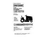
PRODUCT
CONGRATULATIONS
on your purchase of a Sears
Tractor. It has been designed, engineered and manufactured to give you the best possible dependability and
performance.
Should you experience any problem you cannot easily
remedy, please contact your nearest Sears Authorized
Service CentedDepartmento
We have competent, welltrained technicians and the proper tools to service or repair
this tractor.
Please read and retain this manual. The instructions will
enable you to assemble and maintain your tractor properly.
Always observe the "SAFETY RULES".
MODEL
NUMBER
SPECiFiCATiONS
HORSEPOWER:
15.5
GASOLINE CAPACITY
AND TYPE:
t.25 GALLONS
UNLEADED REGULAR
OIL TYPE (APFSF/SG):
SAE 30 (above 32°F)
SAE 5W-30 (below 32°F)
OIL CAPACITY:
3.0 PINTS
SPARK PLUG:
(GAP: .030")
CHAMPION
VALVE CLEARANCE:
LNTAKE:
EXHAUST:
GROUND SPEED (MPH):
FORWARD:
1st
2nd
3rd
4th
5th
6th
REVERSE:
917.259330
SERIAL
NUMBER
DATE OF PURCHASE
'L
THE MODEL AND SERIAL NUMBERS
ON A PLATE UNDER THE SEAT.
WILL BE FO_,ND
_'
YOU SHOULD RECORD BOTH SERIAL NUMBERAND
DATE OF PURCHASE AND KEEP IN A SAFE PLACE
FOR FUTURE REFERENCE.
MAINTENANCE
CUSTOMER
*
Read and observe
the safety
*
Follow a regular schedule
using your tractor.
rules.
in maintaining,
14 PS_
10 PSI
CHARGrNG SYSTEM:
3 AMPS BATTERY
5 AMPS HEADLIGHTS
BATTERY:
AMP/HR:
MIN. CCA:
CASE SIZE:
BLADE BOLT TORQUE:
30-35 FT. LBS.
25
I90
U1R
with a spark arrester meeting applicable local or state laws
(if any). if a spark arrester is used, it should be maintained
in effective working order by the operator.
tn the state of California the above is required by law
(Section 4442 of the California Public Resources Code).
Ottqer states may have similar laws. Federal laws apply on
federal lands. A spark attester for the muffler is available
through your nearest Sears Authorized Service Center/
Department (See REPAIR PARTS section of this manual).
caring for and
,
Follow the instructions
under "Customer
Responsibilities" and "Storage" sections of this owner's manual,
WARNING:
This tractor is equipped
with an internal
combustion
engine and should not be used on or near any
unimproved
forest-covered,
brush-covered
or grass-cov -L
ered land unless the engine's exhaust system is equipped
L MJTED TWO YEAR WARRANTY
Iol
1.5
2.3
3.5
4.4
5.7
1.7
FRONT:
REAR:
is available on this prodstore for details.
RESPONSIBILJT|ES
.005" - .007"
.009" - .0t 1"
TIRE PRESSURE:
AGREEMENT
A Sears Maintenance
Agreement
uct. Contact your nearest Sears
RJ19LM
ON CRAFTSMAN
RID|NG EQUIPMENT
For two (2) years from the date of purchase, if this Craftsman Riding Equipment is maintained, lubricated and tuned up according
to the instructions in the owner's manuaJ, Sears wile repair or replace, free of charge, any parts found to be defective in material or
workmanship.
This Warranty does not cover:
"
Expendabre items which become worn during normal use, such as blades, spark plugs, air cleaners, belts, etc.
•
Tire replacement or repair caused by punctures from outside objects, such as nails, thorns, stumps, or gFass.
Repairs necessary because of operator abuse, negligence, improper storage or accident or the failure to maintain the
equipment according to the instructions contained in the owner's manual.
,,
Riding equipment used for commercial or renta_ purposes.
LIMmTED 90 DAY WARRANTY
ON BATTERY
For ninety (90) days from date of purchase, if any battery included with this riding equipment proves defective in material or
workmanship and our testing determines the battery will not hold a charge, Sears wi_l rep ace the battery at no charge.
IN-HOME WARRANTY SERVICE ON YOUR CRAFTSMAN RIDING EQUIPMENT IS AVAILABLE AT NO-CHARGE FOR 30
DAYS FROM THE DATE OF PURCHASE. PLEASE CONTACT YOUR NEAREST SERVICE CENTER. AFTER 30 DAYS FROM
THE, DAIE OF PURCHASE, WARRANTY SERVtCE IS AVAILABLE BY TAKING YOUR CRAFTSMAN RIDING EQUIPMENT TO
YOUR NEAREST SEARS SERVICE CENTER. (SN-HOME WARRANTY SERVICE WILL STILL 8E AVAILABLE AFTER 30 DAYS
FROM THE DATE OF PURCHASE BUT A STANDARD TRIP CHARGE WILL APPLY.) THIS WARRANTY APPUES ONLY
'_/_ILE THIS PRODUCT IS _NTHE UNITED STATES.
_'-ThisWarranty gives you specific legal rights, and you may also have other rights which may vary from state to state.
,,
SEARS,
°
ROEBUCK
AND CO., D/817 WA, HOFFMAN
3
ESTATES,
IL 60179
TABLE OF CONTENTS
OPERATION ...........................................................
10-14
MAINTENANCE SCHEDULE[" .................................... 15
SERVICE AND ADJUSTMENTS ............................ 20-25
STORAGE ...................................................................
26
TROU BLESHOOTING ............................................
27-28
REPAIR PARTS - TRACTOR ................................. 30°47
REPAIR PARTS - ENGINE .................................... 48-53
PARTS ORDERINGtSERVICE .................. BACK PAGE
SAFETY RULES ...................................... ...................... 2
PRODUCT SPECIFICATIONS ...................................... 3
CUSTOMER RESPONSiBILiTIES
..................... 3, 15o19
WARRANTY ..................................................................
3
TABLE OF CONTENTS ................................................
4
iNDEX ............................................................................
4
TRACTOR ACCESSORIES ......................................... ,5
ASSEMBLY ..................... ........................................... 7-9
X
A
Accessories ............................................ 5
Adjustments:
Brake ...........................................
22
Carburetor ............................. ...... 25
Mower:
Front-To-Back ........................ 21
Side-To-Side .......................... 21
Throttle Control Cable ...... :.......... 24
Air Filter, Engine._ .............................. 18
Air Screen, Engine ............................. 18
Assembly ........................... _............... 7-9
B
Battery:
Cflarging .................................... 7-8
Cleaning ......................................
17
Connecting ................................. 7-8
Starting with Weak Battery ......... 23
Storage .......................................
26
Terminals ....................................
17
Belts:
Motion Drive
RemovaVReplacement ...........
Mower Blade Drive
Removal/Replacement ...........
Blade:
Sharpening ............. _....................
Replacement ...............................
22
22
O
E
Electrical:
Interlocks and Relays ................. 24
Schematic ................................... 29
Wiring Diagram ........................... 30
Engine:
Air Filter ........................................ 18
Air Screen ...................................
18
Cooling Fins, Engine ................... 18
Oil Change .................................. 17
Oil Level .......................... _....... 13,17
Oil Type .......................................
17
Preparation ................................. t3
Repair Parts ............................ 48-53
Starting ........................................
14
Storage ....................................... 26
F
Filters:
Air... .............................................
Fuel .............................................
Fuel:
Type ............................................
Storage ............................. ..........
Fuse ...................................................
16
16
Brake Adjustment... ................ ............ 22
C
Carburetor Adjustment ....................... 25
Controls, Tractor ................... _............ 11
Customer Responsibilities ............. 15-19
Engine:
Air Filter ...................................
18
Air Screen, Engine ................... 18
Battery .................................. ,,, 17
Cooling Fins, Engine ............... 18
Engine Oil ............................... 17
Fuel Filter ................................ 19
Spark Plugs ............................. 19
Tractor:
Blades ...................................... 16
Lubrication Chart ..................... 15
Maintenance Schedule ........... 15
Tire Care ......................... 8,16,23
Cutting Height, Mower ....................... 12
13
26
24
8
H
Hood Removal!Installation
L
Cold Weather Conditions ....... 13,17
Engine .... :....................................
17
Storage .......................................
26
Operation ......................................
t I- 14
Operating Mower ................................ 13
Options:
Accessories.:. ................................ 5
Spark Arrester .......................... 3,40
P
Parking Brake ................................ 11-12
Parts Bag ........... .................................. 6
Parts, Replacement/Repair
........... 30-47
Product Specifications ........................... 3
R
Repair Parts ..................................
18
t9
G
Gauge Wheels .....................................
Oil:
................. 24
Leveling Mower Deck ................. ;....... 21
Lubrication Char .... ............................ 15
M
Maintenance Schedule ....................... 15
Mower:
Adjustment, Front-to-Back .......... 21
Adjustment, Side-to-Side ............ 2 t
Blade Sharpening ....................... 16
Blade Replacement ..................... 16
Cutting Height ............................ t t2
Installation ................................... 20
Operation ..................................... 13
Removal ...................................... 20
Mowing Tips .......................................
t4
Muffler ......... ........................................ 19
Spark Arrester .......................... 3,40
Mulcher Plate .......................................
9
30-47
S
Safety Rules .........................................
2
Seat ......................................................
8
Service and Adjustments .............. 20-25
Brake ....... :.................................... 22
Carburetor ...................................
25
Fuse ..................................... :...... 24
Hood RemoVal/Installation .... :..... 24
,. Motion Drive Belt
Removal/Replacement
........... 22
Mower Blade Drive Belt
Removal/Replacement
........... 22
Mower Adjustment:
Front-to-Back ......................... 21
Side-to-Side ........................... 21
Mower installation ....................... 20
Mower Removal .......................... 20
Tire Care ............................. 8,16,23
Slope Guide Sheet ....... ;..................... 55
Spark Plugs .................... .................... I9
Specifications .......................................
3
Starting the Engine ....................... 13-14
Steering Wheel ................................ 7,23
Stopping theTractor ................. _L....... t2
Storage ................................................
26
T
Throttle Control Cable Adjustment ..... 24
Tires ...........................................
8,16,23
Trouble Shooting Chart .............. :..27-28
Transaxle Repair Parts .................
46-47
W
Warranty ...............................................
Wiring Diagram ..................................
Wiring Schematic ...............................
4
3
30
29
ACCESSOR
S AND ATTA¢
ENTS
These accessories and attachments were available through most Sears retail outlets and service centers when the tractor was purchased.
Most Sears stores can order these items for you when you provide the model number of your tractor.
ENGINE
SPARK PLUG
MAINTENANClE
GAS CAN
AiR FILTER
BLADES
BELTS
%
PERFORMANCE
Sears offers a wide variety of attachments that fit your tractor.
you. This list was current at the time of publication; however,
may be made in these attachments, or some may no longer
accessories and attachments
that are available for your
Most of those attachments do not require additional hitches
attaching and detaching.
Many of these are listed below with brief explanations of how they can help
it may change in future years - more attachments may be added, changes
be available or fit your model. Contact your nearest Soars store for the
tractor.
or conversion kits (those that do are indicated) and are designed for easy
SNOW BLADE forsnow removal only. 14-inch high, 48°inch wide
blade clears 42-inch path when angled reft or dght. Raises, lowers
with side tever, Adjustable skids; replaceable, reversible scraper
bar. (Use with tire chains and whee_ weights and/or rear drawbar
weighL)
SNOWTHROWER has 40-inch swath. Drum-type auger handles
powdery and wet/heavy snow. Mounts easily with simple pin
arrangement. Discharge chute adjusts from tractor seat. 6-inch
diameter spout discharges snow 10 to 50 feet. Lift controlled at
tractor seat. (Use with chains and wheel weights and/or rear
drawbar weight.)
SPRAYERS use 12-volt DC electric motor thai connects to the
tractor battery or other 12*volt source.
Includes booms for
automatic spraying and hand held wand for spot spraying. Wand
has adjustable spray pattern, For applying herbicides, insecticides, fungicides and liquid fertilizers.
SPREADER/SEEDERS
make seeding, fertilizing, and weed killing easy. Broadcast spreaders are atso useful for granular deicers and sand.
AERATOR promotes deep root growth for a healthy lawn. Tapered 2.5-inch steel spikes mounted on 10-inch diameter discs
puncture holes in soil at close intervals to let moisture soak in.
Steel weight tray for increased penetration.
BAGGER lets you collect
grass clippings and leaves for a
healthier, nearer looking lawn. Two Permanex containers hold
30-gallon plastic bags.
BUMPER protects front end of tractor from damage,
CARTS make hauling easy. Variety of sizes available, plus
accessories such as side panel kits, tool caddy, cart cover,
protective mat and doily.
CORING AERATOR takes small plugs outof sol! to atlow moisture and nutrients to roach grass roots. 36-inch swath. 24
hardened steel codng tips. ! 50 tb. capacity weight tray.
EASY OIL DRAIN VALVE makes oil changes easier, faster.
FRONT NOSE ROLLER canters in front of mower dock to reduce
chances of "scalping" on uneven terrain,
GANG HITCH lets you tow 2 or 3 pull-behind attachments at once,
such as sweepers, dethatchers, aerators (not for use with rollers,
carts or other heavy attachments).
GAUGE WHEELS on both sides of the mower deck reduce
chances of "scalping" on uneven terrain. For mower decks not so
equipped.
MULCH RAKF.JDETHATCHER loosens soil and flips thatch and
matted leaves to lawn surface for easy pickup. Twenty spring tine
teeth. Useful to prepare bare areas forseeding. Available for front
or rear mounting.
HiGH PERFORMANCE
REEL-ACT]iON
SPRING TiNS DETHATCHER covers 36-inch wide path and
tosses thatch into large hopper. Mounts behind tractor.
MULCHING CLOSE-OUT PLATE K_T, once installed, lets you
mulch, discharge or bag clippings (bagger optional) without
changing blades. For models not equipped as 3-in-1 Convertible
mowers.
See "MOWER" in the Repair Parts section of this
manual.
SWEEPERS let you Collect grass clippings and leaves.
TtLLER has 5 hp engine and 36qnch swath to prepare seed beds,
cultivate and compost garden residue. Tiller has its own built-in
lift and depth Control system and does NOT require a sleeve hitch.
Fits any lawn, yard or garden tractor. Simply hook up to the tractor
drawbar and go!
Optiona_ accessories
convert unit for
dethatching, aerating, hifling...without tools.
TIRE CHAINS are heavy duty; closely spaced extra-large cross
links give smooth ride, outstanding traction.
TRACTOR CAB has heavy duty vinyl fabric over tubular steel
frame, ABS plastic top; clear plastic windshield offers 360 degree
visibility. Hinged metal doors with catch, Keeps operator warm
and dry, Remove vinyl sides and windshields for use as sun
protector in summer. Optional accessories include:
tinted/
tempered solid safety glass windshield with hand operated wiper;
12-volt amber caution light for mounting on cab top.
VACS for powerful collection of heavy grass clippings and leaves.
Optional wand attachment to pick up debris in hard-to-reach
places. VAC/CHIPPER includes a chipper-shredder.
WEtGHT BRACKET fordrawbar for snow removal applications.
Uses (1) 55 tb. weight.
WHEEL WEIGHTS for rear wheels provide needed traction for
snow removal or dozing hea W materials.
RAMP TOPS AND FEET let you Ioad and unload tractor from a
pickup truck. Use with 2 x 8 or 2 x t0 lumber.
ROLLER for smoother lawn surface.
36-inch wide, 18-inch
diameter water-tight drum holds upto 390 lbs. of weight, Rounded
edges prevent harm to tuff. Adjustable scraper automatically
cleans drum.
5
CONTENTS
Parts Bag contents
OF HARDWARE
shown full size
PACK
Parts packed
separately
in carton
(1) Hex Bolt
3/8-16 x 1
©
Seat
Mulcher
PIate
Steering
Wheel
{1) Lockwasher 3/8
Video
Cassette
(1) kocknut
5/16-18
(1) Hex Bolt 5/!6-18 x 1-t/4
(1) Shoulder Bolt 5/16-18
Manual
(1) Lock
Washer
1/2
(1) Hex Bolt
t/2-13 x t
Steering
Boot
Parts bag contents
,
Parts Bag
not shown full size
(2) Washers 3/8
x 7/8 x 14 Gauge
(2) Shoulder
Bolts
2)lock
CenterNuts
12) Gauge
(2) Screws #10 x 5/8
i'
(2) t.ock Washers
Steering
Extension
Shaft
#10
(2) Washers
3/16 x 3/4 x 16 Gauge
_;-tl
O
Steering Wheel
Adapter
(2) Weld Nuts #
<b
(2) Hex Bolts t/4-20 x 3/4
(2) Keys
Steering
Wheel
Insert
(2) Hex Nuts t/4-20
(2) Latch Hook
Assemblys
9/32 x 5/8 x 16 Gauge
2) Washers
(2) Lock Washers 1/,4
Slope Sheet
6
ASSEMBLY
Your new tractor has been assembled at the factory with exception of those parts left unassembled for shipping purposes.
To ensure safe and proper operation of your tractor all parts and hardware you assemble must be tightened securely. Use
the correct tools as necessary to insure proper tightness.
TOOLS REQUIRED
FOR ASSEMBLY
A socket wrench set will make assembly easier. Standard
wrench sizes are listed.
(1) 5/16" wrench
(1) 3/4" Socket w/drive rachet
(2) 7/i 6" wrenches
Phillips Screwdriver
(!) 1/2" wrench
Tire pressure gauge
(1) 9/16" wrench
Utility knife
When right or left hand is mentioned in this manual, it
means when you are in the operating position (seated
behind the steering wheel).
TO REMOVE; TRACTOR FROM CARTON
UNPACK
,
o
•
CARTON
Remove all accessible loose parts and parts cartons
from carton (See page 6).
Cut, from top to bottom, along lines on all four corners
of carton, and lay panels flat.
Check for any additional loose parts or cartons and
remove.
_.
STEERING
_:_:i!_
BOOT
ADAPTER
BEFORE ROLLING TRACTOR OFF SKID.
ATTACH
STEERING
ASSEMBLE EXTENSION
WHEEL
EXTENSION
SHAFT
(See Fig. 1)
5/16 HEX BOLT
SHAFT AND BOOT
,
Slide extension shaft onto lower steering shaft. Align
mounting holes in extension and lower shafts and
install 5/16 hex bolt and locknut. Tighten securely.
IMPORTANT: TIGHTEN BOLT AND NUT SECURELY TO
18-22 FT. LBS TORQUE.
,
Place tabs of steering boot over tab slots in dash and
push down to secure.
INSTALL STEERING WHEEL
.
,
•
®
,
Position front wheels of the tractor so they are pointing
straight forward.
Slide steering wheel adapter onto steering shaft extension.
Position steering wheel and sleeve assembly so cross
bars are horizontal (left to right) and slide onto adapter.
Assemble large flat washer, 3/8 lock washer, 3/8 hex
bolt and tighten securely.
Snap steering wheel insert into center of steering
wheel.
CONNECT
CAUTION:
TO ROLL TRACTOR
OFF SKID (See Operation section for tocation and function
ef con°
trois)
,
•
(See FiGs. 2 and 3)
Do
not
short
battery
remove metal bracelets,
wristwatch
bands,
etc. connecting battery,
terminals.rings,Before
Positive terminal must be connected
first.to prevent sparking from accidental
grounding.
Remove protective plastic from tractor hood and grill.
IMPORTANT: CHECK FOR AND REMOVE AN'¢ STAPLES
IN SKID THAT MAY PUNCTURE TIRES WHERE TRACTOR
IS TO ROLL OFF SKID.
,
BATTERY
o
o
o
Press lift lever plunger and raise attachment lift lever to
its highest position.
Release parking brake by depressing clutch/brake
pedal.
Place gearshift lever in neutral (N) position.
Roll tractor backwards off skid.
Remove banding holding discharge guard up against
tractor.
o
7
Remove carboard packing from seat pan and lift sea
pan to raised position.
Open batten.! box door.
Be sure battery drain tube is attached to battery box,
Remove terminal protective caps and discard.
If this battery is put into service after month and year
indicated on label (label located between terminals)
charge battery for minimum of one hour at 6-10 amps.
First connect RE D battery cable to positive (+) terminal
with hex bolt, flat washer, lock washer and hex nut as
shown, Tighten securely.
ASSE
LY
•o
Connect BLACK grounding cable to negative (-) termina! with remaining hex bolt, flat washer, lock washer
and hex nut. Tighten securely.
® Close battery box door.
Open battery box door for:
o
Inspection for secure connections (to tighten hardware).
•
Inspection for corrosion.
o Testing battery.
o ' Jumping (if required).
•
Periodic charging..
SEAT
SEAT PAN
\
SHOULDER
BOLT
_T
LOCK WASHER
-6T dRo
TERMINAL
PROTECTIVE
_
t tJ-,\
HEX
NUT
ADJUSTMENT
BOLT
LOCK
WASHER
LARGEFLAT
WASHER
FIG. 4
FLAT,
WASHER
HEX
BOLT
CHECK TiRE PRESSURE
The tires on your tractor were overinflated
shipping purposes. Correct tire pressure
best cutting performance.
,
Reduce tire pressure to PSi shown
SPECIFICATIONS" on page 3 of this
CHECK
PosmvE
(RED)
CABLE
NEGATIVE
(BLACK)
CABLE
FIG. 2
at the factory for
is important for
in "PRODUCT
manual.
DECK LEVELNESS
For best cutting results, mower housing should be properly
leveled.
See "TO LEVEL MOWER HOUSING" in the
Service and Adjustments section of this manual.
CHECK
BELTS
FOR
PROPER
POSITION
OF ALL
See the figures that are shown for replacing motion and
mower blade drive belts in the Service and Adjustments
section of this manual. Verify that the belts are routed
correctly.
SEAT
PAN
CHECK
BATTERY
BOX
DOOR
BRAKE
SYSTEM
After you learn how to operate your tractor, check to see
that the brake is properly adjusted. See "TO ADJUST
BRAKE" in the Service and Adjustments section of this
manua!.
FIG. 3
ASSEMBLE
GAUGE
DECK (See Fig, 5)
WHEELS
TO MOWER
Assemble gauge wheels with tractor on a flat level surface,
INSTALL
SEAT (See Fig. 4)
Adjust seat before tightening adjustment bolt.
•
Remove cardboard packing on seat pan.
o Place seat on seat pan and assemble shoulder bolt.
o
Assembte adjustment bolt, lockwasherandflatwasher
loosely. Do not tighten.
Tighten shoulder bolt securely.
•
Lower seat into operating position and sit on seat.
Slide seat until a comfortable position is reached which
allows you to press clutch!brake pedal all the way
down.
:
Get off seat without moving its adjusted position.
Raise seat and tighten adjustment bolt securely.
•
Adjust mower to desired cutting height (See 'q'O ADJUST MOWER CUTTING HEIGHT" in the Operation
section of this manual).
,
With mower in desired height of cut position, gauge
wheels should be assembled so they are slightly off the
ground. Install gauge wheel in appropriate hole with
shoulder bolt, 3/8" washer and 3/8-16 Iocknut and
tighten securely.
o
Repeat for opposite side installing
same adjustment hole.
gauge wheel in
ASSEMBLY
GAUGE WHEEL
MOUNTING
BRACKET
TO CONVERT TO BAGGING
DRSCHARGJNG
_'>\
OF{
Simply remove mulcher plate and store in a safe place.
Your mower is now ready for discharging or installation of
optional grass catcher accessory.
DEFLECTOR
SHIELD
SHOULDER
3/8" WASHER
BOLT
FiG° 5
iNSTALL MULCHER
(See Figs. 6 & 7)
PLATE
LATCH
HOOKS
install two latch hooks to mulcher plate using screw,
washer, lock washer, and weld nut as shown.
NOTE: Pre-assemble weld nut to latch hook by inserting
weld nut from the top with hook pointing down.
=
Tighten hardware securely.
•
,
Raise and hold deflector shield in upright position.
Place front of mulcher plate over front of mower deck
opening and slide into place, as Shown.
=
FiG. 7
CHECKLIST
BEFORE YOU OPERATE AND EIVJOY YOUR NEW
TRACTOR, WE WISH TO ASSURE THAT YOU RECEIVE
THE BESTPERFORMANCEAND
SA TISFACTION FROM
THIS QUALITY PRODUCT.
Hook front latch into hole on front of mower deck.
Hook rear latch into hole on back of mower deck.
PLEASE REVIEW THE FOLLOWING
CAUTION: Do not remove discharge
guard from mower. Raise and hold
guard when attaching mulcher plate
and allow it to rest, on piate white in
operation.
WELD NUT FROM THE TOP
WELD
NUT_\\,_
HOOK POINTS DOWN
LOCK
WASHER
#"
All assembly instructions have been completed.
¢"
No remaining loose parts in carton.
,/
Batteryis properly prepared and charged.
t hour at 6 amps).
#"
Seat is adjusted comfortably and tightened securely.
J
AHtires are properly inflated. (For shipping purposes,
the tires were overinflated at the factory).
J"
Be sure mowerdeck is properly leveled side-to-side!
front-to-rear for best cutting results. (Tires must be
propedy inflated for leveling).
J
Check mower and drive belts. Be sure they are routed
properly around putleys and inside all belt keepers.
#'
Check wiring. See that all connections are still secure
and wires are properly clamped.
SCREW
LATCH
WASHER
(Minimum
WHILELEARNING HOWTO USE YOUR TRACTOR, PAY
EXTRA A TTENTION TO THE FOLLOWING IMPORTANT
ITEMS:
HOOK
LOCK
WASHER
CHECKLIST:
WELD
NUT
v"
Engine oil is at proper level.
4"
Fuel tank is filled with fresh, clean, regular unleaded
gasoline.
#
Become familiar with all controls - their Iocation and
tunction. Operate them before you start the engine.
,/
Be sure brake system is in safe operating condition.
WASHER
MULCHER
PLATE
FIG, 6
9
OPERATmON
These symbols
may appear
on your tractor or in literature supplied with the product.
Learn and understand
their meaning.
BATTERY
CAUTION OR
.WARNING
REVERSE
FORWARD
FAST
SLOW
ENGINE ON
ENGINE OFF
OIL PRESSURE
CLUTCH
LIGHTS ON
LIGHTS OFF
FUEL
CHOKE
MOWER HEIGHT
DIFFERENTIAL
LOCK
PARKING BRAKE
LOCKED
UNLOCKED
L
REVERSE
MOWER LIFT
NEUTRAL
ATTACHMENT
CLUTCH ENGAGED
HIGH
LOW
ATTACHMENT
CLUTCH DISENGAGED
,
PARKING BRAKE
IGNITION
HYDROSTATIC FREE WHEEL
(Hydro Models only)
DANGER, KEEP HANDS AND FEET AWAY
10
OPERATION
KNOW YOUR TRACTOR
READ THiS OWNER'S
MANUAL
AND SAFETY
RULES
BEFORE
OPERATING
YOUR
TRACTOR
Compare the illustrations with your tractor to famiriadze yourself wfththe locations of various controls and adjustments. Save
this manual for future reference.
ATTACHMENT
CLUTCH LEVER
iGNiTiON
SWITCH
LJGHT SWITCH
POSITION
AMMETER
UFTLEVER
/
THROTTLFJCHOKE
CONTROL
"
%
"
"
=_
/_/
PLUNGER
ATTACHMENT
,'_'=_L|FTLEVER
CLUTCH/BRAKE
PEDAL
HEIGHT
ADJUSTMENT
KNOB
GEARSHIFT
LEVER
FiG. 8
Our tractors conform to the safety standards of the American National Standards institute.
ATTACHMENT CLUTCH LEVER: Used to engage the
mower blades, or other attachments mounted to your
tractor.
LIGHT SWITCH:
GEARSHIFT LEVER: Selects the speed and direction of
tractor.
ATTACHMENT LIFT LEVER: Used to raise and lower the
mower deck or other attachments mounted to your tractor.
Turns the headlights on and off.
THROTTLF_JCHOKE CONTROL:
controlling engine speed.
Used for starting and
LiFT LEVER PLUNGER: Used to release attachment lift
lever when changing its position.
CLUTCH/BRAKE PEDAL: Used fordectutching and braking the tractor and starting the engine.
IGNHTION SWITCH:
engine.
PARKING BRAKE:
brake position.
HEtGHTADJUSTMENT
cutting height.
Locks clutch/brake
pedal into the
AMMETER:
(-).
1t
¸¸
Used for starting and stopping the
KNOB: Used to adjust the mower
indicates battery charging (+) or discharging
OPERATION
over the spectacles or standard safety glasses.
HOW TO USE YOUR TRACTOR
TOSET
PARKHNG BRAKE
NOTE: Under certain conditions when tractor is standing
idle with the engine running, hot engine exhaust gases may
cause "browning" of grass. To eliminate this possibility,
always stop engine when stopping tractor on grass areas.
(See Fig. 9)
Your tractor is equipped with an operator presence sensing
switch. When engine is running, any attempt by the
operator to leave the seat without first setting the parking
brake wiff shut off the engine,
•
Depress clutch/brake
and hold.
pedal into full "BRAKE" position
Place parking brake lever in "ENGAGED" position and
release pressure from clutch!brake pedal. Pedal should
remain in "BRAKE" position. Make sure parking brake
wilt hold tractor secure.
TO USE THROTTLE
.
"DISENGAGED"
POSITION
HEIGHT ADJUSTMENT
is controlled by the
•
Start tractor with clutch/brake pedal depressed and
gearshift lever in neutral (N) position.
,
Move gearshift lever to desired
position.
KNOB
TO ADJUST MOWER
(See Fig. 9)
FiG. 9
STOPPING
(See
•
Slowly release clutch/brake pedal to start movement,
IMPORTANT: BRING TRACTOR TO A COMPLETE STOP
BEFORE SHIFTING OR CHANGING GEARS. FAILURE
TO DO SO WILL SHORTEN THE USEFUL LIFE OF YOUR
TRANSAXLE.
"DISENGAGED"
POSITION
PEDAL
AND BACKWARD
The direction and speed of movement
gearshift lever.
GEARSHIFT
LEVER
'CLUTCH_RAKE
"DRWE"POSmON
Operating engine at tess than fuII throttle reduces the
battery charg!ng rate.
Full throttle offers the best bagging and mower performance,
TO MOVE FORWARD
Fig. 9)
PARKING BRAKE
_"ENGAGED"
POSITION
"BRAKE"
POSITION
(See Fig. 9)
Always operate engine at full throttle.
ATTACHMENT CLUTCH LEVER
"ENGAGED"
POSITION
THROTTLE/
CHOKE
CONTROL
CONTROL
(See Fig. 9)
CUTTING
HE|GHT
MOWER BLADES-
The cutting height iscontrolled by turning the height adjustment knob in desired direction.
,
*
Turn knob clockwise ((_,)
=
Turn knob counterclockwise
height.
Move attachment clutch lever to."DZSENGAGED" positiono
GROUND DRIVE ,
Depress clutch/brake pedal into full "BRAKE" position.
Move gearshift
ENGINE =
position.
NOTE: Failure to move throttle control to slow (_)
position and allowing engine to idle before stopping may
cause engine to "backfire".
,
o
(_#-'_) to lower cutting
The cutting height range is approximately 1-1/2" to 4". The
heights are measured from the gt_oundto the blade tip with
the engine not running. These heights are approximate
and may vary depending upon soil conditions, height of
grass and types of grass being mowed.
The average lawn should be cut to approximately 2-1/2
inches during the coot season and to over 3 inches
during hot months. For healthier and better looking
_awns, mow often and after moderate growth.
lever to neutral (N) position.
Move throttle control to slow (_)
to raise cutting height,
Turn ignition,key to "OFF" position and remove key.
Always remove key when leaving tractor to prevent
unauthorized use.
,
Never use choke to stop engine.
!2
For best cutting performance, grass over 6 inches in
height should be mowed twice. Make the first cut
relatively high; the second to desired height.
OPERATIC
TO OPERATE
MOWER
o
(See Fig. 10)
Your tractor is equipped with an operator presence sensing switch. Any attempt by the operator to leave the seat
with the engine running and the attachment clutch engaged
will shut off the engine.
,
,
-
To restart movement, slowly release parking brake and
clutch!brake pedal.
Make all turns slowly.
TO TRANSPORT
Select desired height of cut.
Lower mower with attachment lift control.
o
Raise attachment
ment lift control.
Start mower blades by engaging attachment clutch
control.
o
When pushing or towing your tractor, be sure gearshift
lever is in neutral (N) position.
TO STOP MOWER BLADES - disengage attachment
clutch control.
o
Do not push or tow tractor at more than five (5) MPH.
NOTE: To protect hood from damage when transporting
your tractor on a truck or a trailer, be sure hood is dosed and
secured to tractor. Usean appropriate means oftying hood
to tractor (rope, cord, etc.).
CAUTION: Do not operate the mower
without either the entire grass catcher,
on mowers so equipped, or the discharge guard in place,
ATTACHMENT
"DISENGAGED"
CLUTCH LEVER
POSiTiON
\
lift to highest position with attach-
BEFORE
CHECK
"ENGAGED"
POSITION
STARTING
ENGINE
THE ENGINE
OiL LEVEL (See Fig. 16)
o
The engine in your tractor has been shipped, from the
factory, already filled with summer weight oil,
o
Check engine oil with tractor on level ground,
Remove oil fill cap!dipstick and wipe clean, reinsert the
dipstick and Screw cap tight, wait for a few seconds,
remove and read oil level, if necessary, add oil until
"FULL" mark on dipstick is reached. Do not overfill.
For cold weather operation you should change oil for
easier starting (See "OIL VISCOSITY CHART" in the
Customer Responsibilities section of this' manual).
=
To Change engine oil, see the Customer ResponsibiIF
ties section in this manual.
ADD GASOLINE
o
DISCHARGE
GUARD
Fill fuel tank. Use fresh, clean, regular unleaded
gasoline with a minimum of 87 octane. (Use of ieaded
gasoline wilt increase carbon and lead oxide deposits
and reduce valve life). Do not mix oil with gasoline.
Purchase fuel in quantities that can be used within 30
days to assure fuel freshness.
fMPORTANT: WHEN OPERATING IN TEMPERATURES
BELOW 32°F(0°C), USEFRESH, CLEAN WINTER GRADE
GASOLINE TO HELP INSURE GOOD COLD WEATHER
STARTING.
i
FIG. 10
TO OPERATE
WARNING:
Experience indicates that alcohol blended
fuels (called gasohol or using ethanol or methanol) can
attract moisture which leads to separation and formation of
acids during storage. Acidic gas can damage the fuel
system of an engine while in storage. To avoid engine
problems, the fuel system should be emptied before storage of 30 days or longer. Drain the gas tank, start the
engine and let it run untit the fuel lines and carburetor are
empty. Use fresh fuel next season. See Storage Instructions for additional information.
Never use engine or
carburetor cleaner products in the fuel tank or permanent
damage may occur.
ON HILLS
CAUTION:
Do not drive up or down
hills with slopes greater than 15° and
do not drive across any slope.
,
Choose the slowest speed before starting up or down
hills.
o
Avoid stopping or changing speed on hills.
If slowing is necessary, move throttle control lever to
slower position.
o
If stopping is absolutely necessary, push clutch/brake
pedal quickly to brake position and engage parking
brake.
Move gearshift lever to 1st gear. Be sure you have
allowed room for tractor to roll slightly as you restart
movement.
CAUTION: FiN to bottom of gas tank
filler neck, Do not overfiiL Wipeoffany
spilled oiJ or fuel. Do not store, spill or
13
!
OPERATION
TO START
ENGINE
(See Fig. 9)
When starting the engine for the first time or if the engine
has run out of fuel, it will take extra cranking time to move
fuel from the tank to the engine.
o
Depress clutch/brake pedal and set parking brake.
o
o
Place gear shift lever in neutral (N) position.
Move attachment clutch to "DISENGAGED" position.
•
Move throttle control to choke (N)
If grass is extremely tall, it should be mowed twice to
reduce Ioad and possible fire hazard from dried clippings. Make first cut relatively high; the second to the
desired height.
•
Do not mow grass when it is wet. Wet grass will plug
mower and leave undesirable clumps. AItow grass to
dry before mowing.
=
Always operate engine at full throttle when mowing to
assure better mowing performance and proper discharge of material. Regulate ground speed by selecting a low enough gear to give the mower cutting
performance as welt as the quality of cut desired.
o
When operating attachments, select a ground speed
that will suit the terrain and give best performance of
the attachment being used.
position.
Note: Before startin_g, read the warm and cold starting
procedures below.
•
o
Insert key into ignition and turn key clockwise to"START"
position and release key as soon as engine starts. Do
not run starter continuously for more than fifteen seconds per minute. If the engine does not start after
several attempts, move throttle control to fast (,_)
position, wait afew minutes and try again. If engine still
does not start, move the throttle control back to the
choke (N) position and retry.
WARM WEATHER STARTING (50 ° F and above)
o
When engine starts, move the throttle control to the fast
(,_) position.
•
The attachments and ground drive can now be used. If
the .engine does not accept the load, restart the engine
and allow it to warm up for one minute using the choke
as described above.
FIG. 11
MULCHING
MOWING
TiPS
COLD WEATHER STARTING ( 50°F and below)
iMPORTANT:
FOR BEST PERFORMANCE,
KEEP
MOWER HOUSING FREE OF BUILT-UP GRASS AND
TRASH. CLEAN AFTER EACH USE.
o
When engine starts, allow engine to run with the throttle
control in the choke (N) position until the engine runs
• roughly, then move throttle control to fast (,_) position.
This may require an engine warm-up period from
several seconds to several minutes, depending-on the
temperature.
,
o
The attachments can also be used during the engine
warm-up period.
The special mulching blade will recut the grass clippings many times and reduce them in,size so that as
they fall onto the lawn they will disperse into the grass
and not be noticed. Also, the mulched grass will
biodegrade quickly to provide nutrients for the lawn.
Always mulch with your highest engine (blade) speed
as this will provide the best recutting action of the
blades.
,
Avoid cutting your lawn when it iswet. Wet grass tends
to form clumps and interferes with the mulching action.
The best time to mow your lawn is the early afternoon.
At thistime the grass has dried and the newly cut area
wilt not be exposed to the direct sun.
•
For best results, adjust the mower cutting height so that
the mower cuts off only the top one-third of the grass
blades (See Fig. 12). For extremely heavy mulching,
reduce you r Width of cut and mow slowly.
Certain types of grass and grass conditions may require that an area be mulched a second time to completely hide the clippings. When doing a second cut,
mow across or perpendicular to the first cut path,
NOTE; If at a high altitude (above 3000 feet) or in cold
temperatures (below 32 F) the carburetor fuel mixture may
need to be adjusted for best engine performance. See "TO
ADJUST CARBURETOR" in the Service and Adjustments
section of this manual.
MOWING
TIPS
•
Tire chains cannot be used when the mower housing is
attached to tractor.
=
Mower should be properly leveled for best mowing
performance. See "TO LEVEL MOWER HOUSING" in
the Service and Adjustments section of this manuaI.
The left hand side of mower should be used for trimming.
•
°
Drive so that clippings are discharged onto the area
that has been cut. Have the cut area to the right of the
machine, This wilt result in a more even distribution of
clippings and more uniform cutting:
•
When mowing large areas, start by turning to the right
so that clippings will discharge away from shrubs,
fences, driveways, etc. After one or two rounds, mow
in the opposite direction making left hand turns until
finished (See Fig. tl ).
°
°
Change your cutting pattern from week to week. Mow
north to south one week then change to east to west the
next week. This will help prevent matting and graining
of the lawn,
MAX 1/3
!4
FiG. !2
CUSTOME
:ESPO
IL
ES
:
MAINTENANCE
SCHEDULE
FiLL IN DATES
AS YOU COMPLETE
REGULAR SERVICE
Check
SERVICE DATES
Brake Operation
.....
Check Tire Pressure
6#4
$4#
....
Check
fort.oose
Feste.ers
_'
!
....
SharpentRe_tace
Mowtr
'B_ades .........................
V',
Lubrication
Chart
_
.....
Check
....
, ,
_#_
......
:
_#_
............
Transaxle
Adjus!,B!ad,e
,,,,,, , ......
Cooling
_##
Bett(S) Tension
_#'_
Adjust
Motion Drive Belt(s) Tension
_5
Check
Engine
Change
Oil L,e,vel
_: :,_##_
Engine Oil
...._
_
Clean Air Filter
......
_#2
,
Replace
..........
_/'2
Spark Plug
_
....................
_,'_
Fuel Filter
- Change more often when operating under a heavy toad or in high ambient temperatures°
- Service more often whe_ operating in dirty or dusty conditions.
- tf equipped _th Oilfilter, change oil eve_ 50 hours•
- Replaceblades more often when mowing in sandy soil.
GENERAL
I .......................
_,2
Fins
Replace
AirF!!!er
paper
Cartriege
Replace
J
Oil Filter (lf equipped)
Cooling
¢
I_2
EnspectMuffler/S,p,a,rk,
Arrester .......
Clean Engine
I
............................
i
............
,d2,3
Clean Air Screen
Replace
'
i .........
Battery Level(Recharge
Clean Battery and Terminals
Check
V'7
RECOMMENDATIONS
5 - If equipped with adjustablesystem,
6 - Not requiredIf equippedwith maintenance4ree battery,
7 - Tightenfront axle pivot bolt to 35 ft.4bs, ma×im_m.
Do notovertighten.
LUBRICATION
CHART
The warranty on this tractor does not cover items that have
been subjected to operator abuse or negligence.
To
receive full value from the warranty, operator must maintain
tractor as instructed in this manual.
Some adjustments will need to be made periodically to
properly maintain your tractor.
All adjustments in the Service and Adjustments section of
this manual should be checked at least once each season.
o
BEFORE
(9
CLUTCH
PIVOT(S)
EACH USE
°
Check engine oil level.
,
•Check brake operation.
,
o
®
Once a year you should replace the spark plug, clean
or repface air filter, and check blades and belts for
wear. A new spark plug and clean air filter assure
proper air-fuel mixture and help your engine run better
and last longer.
PIVOTS
Check tire pressure.
Check for loose fasteners.
(_
SAE 30 OR 10W30 MOTOR OIL
®
GENERAL
®
REFER 1tO CUSTOMER
O
PURPOSE GREASE
RESPONSIBlUTIES
"ENGINE"
SECTION
_MPORTANT:
DO NOT OIL OR GREASE
THE PIVOT POINTS
WHICH HAVE SPECIAL
NYLON BEARINGS•
VISCOUS
LUBRICANTS WILL ATTRACT
DUST AND DIRT THAT WILL SHORTEN
THE LIFE OF THE SELF-LUBRICATING
BEARINGS.
IF YOU
FEEL THEY MUST BE LUBRICATED,
USE ONLY A DRY, POW_5
DERED
GRAPHITE
TYPE
LUBRICANT
SPARINGLY,
BILITIES
CUSTOMER RESPO
TRACTOR
Always observe safety rules when performing any maintenance.
MANDREL
ASSEMBLY
BLADE
BRAKE OPERATION
If tractor requires more than six (6) feet stopping distance
at high speed in highest gear, then brake must be adjusted.
(See "TO ADJUST BRAKE" in the Service and Adjustments section of this manual).
TRAILING
EDGE
LOCK
TmRES
*
Maintain proper air pressure in all tires (See "PRODUCT SPECIFICATIONS" on page 3 of this manual).
o
Keep tires free of gasoline, oil, or insect control chemicals which can harm rubber.
o
Avoid stumps, stones, deep ruts, sharp objects and
other hazards that may cause tire damage.
BLADE
REMOVAL
FiG. 13
TO SHARPEN
Re-
Raise mower to highest position to allow access to
blades.
,
Remove hex bolt; lock washer and flat washer securing
blade.
°
Install new or resharpened blade with trailing edge up
towards deck as shown.
,
Reassemble hex bolt, lock washer and flat washer in
exact order as shown.
BLADE (See Fig, 14)
Care should be taken to keep the blade balanced. An
unbalanced blade will cause excessive vibration and eventuai damage to mower and engine.
(See Fig. 13)
o
___
*A GRADE 8 HEAT TREATED BOLT CAN BE
iDENTIFIED BY SIX LINES ON THE BOLT HEAD.
CARE
For best results mower blades must be kept sharp.
place bent or damaged blades.
BLADE
HEX BOLT
FLAT WASHER
(GRADE
8)*
°
Tighten bolt securely (30-35 Ft. Lbs. torque).
iMPORTANT: BLADE BOLT IS GRADE 8 HEATTREATED.
o
The biade can be sharpened with a file or on a grinding
wheel. Do not attempt to sharpen while on the mower.
•
To check blade balance, you wilt need a 5/8" diameter
steel bolt, pin, ora cone balancer. (When using a cone
batancer, follow the instructions supplied with balancer).
Slide blade on to an unthreaded portion of the steel bolt
or pin and hold the bolt or pin parallel with the ground.
If blade is balanced, it should remain in a horizontal
position, tf either end of the blade moves downward,
sharpen the heavy end until the blade is balanced.
NOTE: Do not use a nail for balancing blade. The lobes of
the center hole may appear to be centered, but are not.
NOTE: We do not recommend sharpening blade - but if you
do, be sure the blade is balanced.
CENTER HOLE
BLADE
5/8" BOLT
OR PIN
j'
FiG. 14
16
,
CUSTOMER
ESPONS!
BATTERY
NOTE: Although multi-viscosity oils (5W30, 10W30 etc.)
improve starting in cold weather, these multi-viscosity oils
will result in increased oil consumption when used above
32°F. Check your engine oil level more frequently to avoid
possible engine damage from running Iow on oil.
Your tractor has a battery charging system which is sufficient for normal use, However, periodic charging of the
battery with an automotive charger will extend its life.
•
Keep battery and terminals clean.
o
Keep battery bolts tight.
•
Recharge at 6-!0 amperes for 1 hour,
LITMES
Change the oil after the first two hours of operation and
every 25 hours thereafter or at least once a year if the
tractor is not used for 25 hours in one _'ear.
Keep small vent holes open,
Check the crankcase oii tevel before starting the engine
and after each eight (8) hours of operation. Tighten oil fill
cap!dipstick securely each time you check the oil level.
TO CLEAN BATTERY AND TERMINALS
Corrosion and dirt on the battery and terminals can cause
the battery to "leak" power.
TO CHANGE ENGINE OIL (See Figs. 15 and 16)
•
Open battery box door,
Determine temperature range expected before oil change.
All oil must meet APf service classification SFor SG.
•
Disconnect BLACK battery cable first then RED battery cable and remove battery from tractor.
o
Be sure tractor is on leve! surface.
,
Rinse the battery with plain water and dry.
°
•
Clean terminals and battery cable ends with wire brush
until bright.
Oi_ wilt drain more freely when warm.
Catch oil in a suitable container.
o
Remove oil fill cap/dipstick. Be careful not to allow dirt
to enter the engine when changing oil.
®
Remove drain plug,
Coat terminals with grease or petroleum jelly,
Reinstall battery (See "CONNECT BATTERY" in the
Assembly section of this manual).
After oil has drained comp!etely, replace oil drain plug
and tighten securely.
o
V-BELTS
Check V-belts for dete rioration and wear after 100 hours of
operation and replace if necessary. The belts are not
adjustable, Replace belts if they begin to slip from wear,
TRANSAXLE
Refill engine with oil through oil fill dipstick tube, Pour
slow{y, Do not overfill, For approximate capacity see
PRODUCT SPECIFICAT ONS on page 3 of this
manual
Use gauge on oil fill cap/dipstick for checking level. Be
sure dipstick cap is tightened securely for accurate
reading. Keep oi! at "FULL" line on dipstick.
COOLING
Keep transaxle free from build-up of dirt and chaff which
can restrict cooling.
OiL FILL
CAP/DIPSTICK
ENGINE
LUBRiCATiON
Only use high quality detergent oil rated with API service
classification SF or SG. Select the oil's SAE viscosity grade
according to your expected operating temperature,
OIL DRAIN
PLUG
SAE VrSCOSITY GRADES
FiG. 16
17
CUSTO
AIR FILTER
ER
SPONSlBILITIES
(See Fig, 17)
CLEAN
Your engine will not run properly using a dirty air filter.
Clean the foam pre-cleaner after every 25 hours of operation or every season. Service paper cartridge every 100
hours of operation or every season, whichever Occurs first.
(See Fig. 18)
Air screen must be kept free of dirt and Chaff to prevent
engine damage from overheating. Clean with a wire brush
or compressed air to remove dirt and stubborn dried gum
fibers.
Service air cleaner more often under dusty conditions.
-
AIR SCREEN
ENGINE
Remove knob(s) and cover.
COOLING
FINS (See Fig. 18)
TO SERVICE PRE-CLEANER
Remove any dust, dirt or oil from engine cooling fins to
prevent engine damage from overheating.
o
Slide foam pre-c!eaner off Cartridge.
•
o
Wash it in liquid detergent and water.
Remove screws from blower housing and lift housing
and dipstick tube assembly off engine.
o
Squeeze it dry in a clean cloth.
-
Cover oil fill opening to prevent entry of dirt.
,
Saturate it in engine oil. Wrap it in clean, absorbent
Cloth and squeeze to remove excess oil.
°
Use compressed air or stiff bristle brush tothoroughly
clean engine cooling fins.
•
tf very dirty or damaged, replace pre-cieaner.
To reassemble, reverse above procedure.
Reinstall pre-cteaner over cartridge.
BLOWER
HOUSING
Reinstall cover and secure with knob(s).
TO SERVICE CARTRIDGE
SCREWS
•
Remove cartridge nut.
•
Carefully remove cartridge to prevent debris from entering carburetor.
Clean base carefully to prevent
debris from entering carburetor.
,
Clean cartridge by tapping gently on flat surface, tfvery
dirty or damaged, replace cartridge.
SCREWS
AIR SCREEN
o
Reinstall cartridge, nut, precteaner, cover and secure
with knob(s).
IMPORTANT:
PETROLEUM SOLVENTS, SUCH AS
KEROSENE, ARE NOT TO BE USED TO CLEAN THE
CARTRIDGE. THEY MAY CAUSE DETERIORATION OF
THE CARTRIDGE. DO NOT OIL CARTRIDGE. DO NOT
USE PRESSURIZED
AlR TO CLEAN
OR DRY
CARTRIDGE.
DIPSTICK
TUBE
ASSEMBLY
SPARK
PLUG
COVER KNOB_"_--"_"_
ENGINE
COOLING
FINS
COVER
CARTRIDGE
FOAM
PRE-CLEANER'-"--"
NUT
FIG.18
PAPER
CARTRIDGE
FIG. 17
18
CUSTO
E
ESPONS
LITUES
MUFFLER
CLAMP
inspect and replace corroded muffler and spark attester (if
equipped) as it could create a fire hazard and!or damage.
SPARK
CLAMP
PLUGS
Replace spark plugs at the beginning of each mowing
season or after every I00 hours of operation, whichever
occurs first. Spark plug type and gap setting are shown in
"PRODUCT SPECIFICATIONS" on page 3 of this manual.
HN-LINE FUEL FILTER
FUEL
(See Fig. 19)
FIG. 19
The fuel filter should be replaced once each season. If fuel
filter becomes clogged, obstructing fuel flow to carburetor,
replacement is required.
CLF..ANING
Clean engine, battery, seat, finish, etc. of all foreign
matter.
•
With engine cool, remove filter and ptug fuel line
sections.
,
Place new fuel filter in position in fuel line with arrow
pointing towards carburetor.
,,
Keep finished surfaces and wheels free of at! gasoline,
oil, etc.
•
Be sure there are no fuel line leaks and clamps are
properly positioned.
•
Protect painted surfaces with automotive type wax.
•
Immediately wipe up any spilled gasoline.
We do not recommend using a garden hose to clean your
tractor unless the electrical system, muffler, air filter and
carburetor are covered to keep water out. Water in engine
can result in a shortened engine life.
19 ¸
SERVICE A
CAUTION:
=
_-
BE;FORE PERFORMING ANY SERVICE OR ADJUSTMENTS:
Place gearshift _ever in neutral (N) position.
Depress
c]utchlbrake
pedal
fully and set parking
brake.
Place attachment
clutch
in "DKSENGAGED"
position.
Turn ignition key "OFF" and remove key.
Make sure the blades and all moving parts have completely stopped,
Disconnect spark ptug wire from spark plug and place wire where it cannot come in contact with
p|ug.
,
,
...........
ADJUSTMENTS
,.=
....
TRACTOR
TO REMOVE
CLUTCH
MOWER
CLUTCH
ROD
(See Fig. 20)
RETAINER
SPRING
Mower will be easier to remove from the right side of tractor.
,
Place attachment clutch in "DISENGAGED" position.
Move attachment lift lever forward to lower mower to its
lowest position.
•
Roll belt off engine pulley.
•
Disconnect clutch rod from clutch lever by removing
retainer spring,
-
Disconnect anti-sway bar from chassis bracket by
removing retainer spring.
,
Disconnect suspension arms from rear deck brackets
by removing retainer springs.
Disconnect front iinks from deck by removing retainer
springs.
Raise lift lever to raise suspension arms. Slide mower
out from under tractor.
•
•
ENGINE
FRONT
LINK
RETAINER
SPRINGS
(BOTH
SIDES)
SPRING
IMPORTANT:
IF AN ATTACHMENT OTHER THAN THE
MOWER tS TO BE MOUNTED TO THE TRACTOR,
REMOVE THE FRONT LINKS.
TO UNSTALL MOWER
RETAINER
,SPRINGS
(See Fig, 20)
(BOTH SIDES)
Raise attachment lift lever to its highest position.
-
Slide mower under tractor with discharge guard to dght
side of tractor.
*
Lower lift lever to its lowest position.
,
Install mower in reverse order of removal instructions.
FiG. 20
2O
SERVICE A
TO LEVEL MOWER
ADJUSTMENTS
HOUSING
FRONT-TO-BACK ADJUSTMENT (See Figs. 23 and 24)
_MPORTANT: DECK MUST BE LEVEL SIDE-TO-SIDE. fF
THE FOLLOWING FRONT-TO-BACK ADJUSTMENT IS
NECESSARY, BE SURE TO ADJUST BOTH FRONT LINKS
EQUALLY SO MOWER WILL STAY LEVEL SIDE-TOSIDE.
Adjust the mower while tractor is parked on level ground or
driveway,
Make sure tires are properly inflated (See
"PRODUCT SPECIFICATIONS" on page 3 of this manual).
If tires are over or underinfiated, you will not properly adjust
your mower.
To obtain the best cutting results, the mower housing
should be adjusted so that the front is approximately 1/4" to
3/4" lower than the rear when the mower is in. its highest
position.
Check adjustment on right side of tractor. Measure distance "D" directly in front and behind the mandrel at bottom
edge of mower housing as shown.
Before making any necessary adjustments, check that
both front links are equal in length. Both links should be
approximately 10-3/8".
•
tf links are not equal in length, adjust one link to same
length as other link.
To lower front of mower loosen nut "E" on both front
links an equal number of turns.
When distance "D" is 1/4" to 3/4" lower at front than
rear, tighten nuts "F" against trunnion on both front
links.
o To raise front of mower, loosen nut,,F, from trunnion on
both front links. Tighten nut "E" on both front links an
equal number of turns.
When distance "D" is 1/4" to 3/4" lower at front than
rear, tighten nut"F" against trunnion on both front links.
°
Recheck side-to-side adjustment.
SIDE-TO-S_DE ADJUSTMENT (See Figs. 21 and 22)
Raise mower to its highest position.
,
At the midpoint of both sides Ofmower, measure height
from bottom edge of mower to ground. Distance "A" on
both sides of mower should be the same or within 1/4"
of each other.
•
If adjustment is necessary, make adjustment on one
side of mower only.
To raise one side of mower, tighten lift link adjustment
nut on that side.
To lower one side of mower, loosen lift link adjustment
nut on that side.
NOTE: Each full turn of adjustment nut will change mower
height about t/8".
•
Recheck measurements
after adjusting.
BOTTOM EDGE
OF MOWER TO
GROUND
BOTTOM EDGE
OF MOWERTO
GROUND
\
GROUND LINE
<_ %",, "',,
A
i
_ o/
MANDREL
FIG, 21
SUSPENSION
ARM
,,,
FiG. 23
BOTH FRONT LINKS MUST BE EQUAL
LiFT LiNK
ADJUSTMENT
iN LENGTH
NUT
FiG. 22
NUT"E"
NUT "F"
FRONT LINKS
21
TRUNNION
FiG. 24
,, i
SERVICE
TO REPLACE
MOWER
BLADE
AND ADJUSTMENTS
DRIVE
WiTH PARKING
BELT
BRAKE "ENGAGED"
(See Fig. 25)
The mower blade drive belt may be replaced without tools.
Park the tractor on level surface. Engage parking brake.
BELT REMOVALo
Remove mower from tractor (See 'q'O REMOVE
MOWER" in this section of this manual).
o
Work belt off both mandrel pulleys and idler pulleys.
o
Pull belt away from mower.
NUT "A"
JAM NUT
•
BELT INSTALLATION o
Install new belt in reverse order of removal.
•
°
Make sure bert is in all pulley grooves and inside all belt
guides.
Install mower in reverse order of removal instructions.
_
OPERATING
ARM
FiG. 26
MANDREL
PULLEY
IDLER
PULLEYS
TO REPLACE
(See Fig. 27)
MOTION
DRWE
BELT
Park the tractor on level surface. Engage parking brake.
For assistance, there is a belt installation guide decal on
bottom side of left footrest.
•
Remove mower (See "TO REMOVE MOWER" in this
section of this manual.)
•
Remove upper belt keeper.
Remove belt from stationary idler and clutching idler.
Pull belt slack toward rear of tractor. Remove belt
upwards from transaxle pulley by deflecting belt keepers.
,
MANDREL
PULLEY
,
install new belt by reversing above procedure.
IMPORTANT:
MAKE SURE UPPER BELT KEEPER IS
PosITIONED PROPERLY BETWEEN LOCATOR TABS.
FIG. 25
TO ADJUST
BRAKE
Pull belt toward front of tractoi" and remove downwards
from around engine pultey.
(See Fig. 26)
PULLEY
Your tractor is equipped with an adjustable brake system
which is mounted on the right side of the transaxte.
LOCATOR
CLUTCHING
IDLER
TABS
If tractor requires more than six (6) feet stopping distance
at high speed in highest gear, then brake must be adjusted.
•
Depress clutch/brake pedal and engage parking brake.
•
Measure distance between brake operating arm and
nut "A" on brake rod.
iDLER
tf distance is other than 1-1/2", loosen jam nut and turn
nut "A" until distance becomes 1-1/2". Retighten jam
nut against nut "A".
PULLEY
Road test tractor for proper stopping distance as stated
above. Readjust if necessary. If stopping distance is
stili greater than six (6) feet in highest gear, further
maintenance is necessary. Contact your nearest authorized service center/department.
FIG. 27
22
SERVICE AN
TRANSAXLE
SHIFTER
LmNKAGE AND
JUSTMENT
(See Figs, 28 and 29)
ADJUSTMENTS
AD=
TO REMOVE WHEEL
(See Fig. 30)
The transaxle should be in neutral when the gear shift lever
is in the neutral (N) (lock gate) position. The adjustment is
preset at the factory; however, if adjustment is needed,
proceed as follows:
,
Make sure transaxle is in neutral (N),
Loosen two Iocknuts on tie rod.
e
Turn center rod until gearshift lever falls into neutral
lock gate on fender console,
o
FOR REPAHRS
Block up axle securely.
Remove axle cover, retaining ring and washers to allow
wheel _'emoval (rear wheel contains a square key - Do
not 10se),
Repair tire and reassemble.
On rear wheels only: align grooves in rear wheel hub
and axle. Insert square key.
Replace washers and snap retaining ring securely in
axle groove,
Tighten Iocknuts securely.
Replace axle cover.
"WASHERS
RETAINING
RiNG
FIG, 28
AXLE
LOCKNUTS
\
COVER
SQUARE KEY
(REAR WHEELONLY)
i
FIG= 30
CENTER
ROD
TO START ENGINE WITH A WEAK
(See Fig. 31)
,_ L
--
TRANSAXLE
STEERING
WHEEL ALIGNMENT
TO ATTACH JUMPER CABLES -
If steering wheel crossbars are not horizontal (left to right)
when wheels are positioned straight forward, remove steeringwheel and reassemble per instructions in the Assembly
section of this manua!.
FRONT WHEEL
CAUTION: Lead-acid batteries gonerate e×p_osive gases. Keep sparks, flame
and smoking materials away from batteries.
Always wear eye protection
when around batteries.
!
|
I
i
if your battery is too weak to start the engine, it should be
recharged.
If "jumper cables" are used for emergency
starting, follow this procedure:
IMPORTANT:
YOUR TRACTOR IS EQUIPPED WITH A t 2
VOLT NEGATIVE
GROUNDED
SYSTEM:
THE OTHER
VEHICLE
MUST ALSO
BE A 12 VOLT
NEGATIVE
GROUNDED
SYSTEM.
DO NOT USE YOUR TRACTOR
BATTERY TO START OTHER VEHICLE_.
FIGo 29
TO ADJUST
BATTERY
Connect each end of the RED cabFe to the POSITIVE
(+) terminal of each battery, taking care not to short
against chassis.
,
Connect one end of the BLACK cable to the NEGATIVE (-) terminal of fully charged battery.
•
Connect the other end of the BLACK cable to good
CHASSIS GROUND, away from fuel tank and battery.
TOE4N/CAMBER
The front wheel toe-in and camber are not adjustable on
your tractor, if damage has occurred to affect the front
wheel toe-in or camber, contact your nearest authorized
service center/department.
TO REMOVE CABLES, REVERSE ORDER •
23
BLACK cable first from chassis and then from the fully
charged battery.
RED cable last from both batteries.
$ERVmCE AN
POSiTiVE TERMINAL
NEGATIVE
ADJUSTMENTS
TERMINAL
HOOD
HEADL|GHT
WIRE
CONNECTOR
CABLES
FiG. 32
CHARGED
BATTERY
POSITIVE TERMINAL
NEGATIVE
ENGINE
TO ADJUST THROTTLE
(See Fig, 33)
TERMINAL
FIG. 3t
TO REPLACE
HEADLIGHT
BULB
Raise hood.
o
Pull bulb holder out of the hole in the backside of the
grill.
Replace bulb in holder and push bulb holder, securely
back into the hole in the backside of the grill
Close hood.
,
With engine not running; move throttle control lever
from slow (_) to choke ({\1) position. Slowly move
lever from choke (1_1)
to fast (,_) position.
=
Check that holes "A" in governor control lever and hole
in governor plate line-up, tf holes "A" are not aligned,
loosen clamp screw and move throttlecable until holes
are aligned. Tighten clamp screw securely.
AND RELAYS
GOVERNOR
CONTROL LEVER
Loose or damaged wiring may cause your tractor to run
poorly, stop running, or prevent it from starting.
*
CABLE
The throttle control has been preset at the factory and
adjustment should not be necessary. Check adjustment as
described below before loosening cable. If adjustment is
necessary, proceed as follows:
=
iNTERLOCKS
CONTROL
GOVERNOR
CONTROL PLATE
Check wiring. See electrical wiring diagram in the
Repair Parts section of this manual.
TO REPLACE
FUSE
Replace with 30 amp automotive-type plug-in fuse, The
fuse holder is located behind the dash.
TO REMOVE HOOD
(See Fig. 32) '
AND GRILL
ASSEMBLY
,
Raise hood.
•
Unsnap headlight wire connector.
•
Stand in front of tractor. G rasp hood at sides, tilt toward
engine and lift off Of tractor.
•
To replace, reverse above procedures.
HOLES "A"
CLAMP
SCREW
FiG, 33
24
THROTTLE
CABLE
SERVmCE A
D ADJUSTMENTS.
TO ADJUST CARBURETOR (See Fig, 34)
ACCELERATION
The carburetor has been preset at the factory and adjustment should not be necessary. However, minor adjustment may be required to compensate for differences in fue!,
temperature, altitude or load. If the carburetor does need
adjustment, proceed as follows:
.
In general, turning idle mixture valve in (clockwise) decreases the supply of fuel to the engine giving a leaner fuel/
air mixture, Turning the idle mixture valve out (counterclockwise) increases the supply of fuel to the engine giving
a richer fuel!air mixture.
High speed stop is factory
damage may result.
o
Move throttle control lever from slow (_t_) to fast ("t!_)
position.
If engine hesitates or dies, turn idle mixture
valve out (counterclockwise)
!/8 turn. Repeat test and
continue to adjust, if necessary,
until engine accelerates smoothly°
adjusted.
SETTING -
Air cleaner assembly must be assembled to the carburetor when making carburetor adjustments.
THROTTLE
LEVER
Be sure the throttle control cable is adjusted properly
(see above).
IDLE SPEED
SCREW
.
With engine off turn idle mixture valve in (clockwise)
closing it finger tight and then turn out (counterclockwise) I full turn.
FINAL SETTING-
.
Start engine and allow to warm for five minutes. Make
final adjustments with engine running and shift/motion
control lever in neutral (N) position.
•
Move throttle control lever to slow (_) position. With
finger, rotate and hold throttle lever against idle speed
screw. Turn idle speed screw to attain 1750 RPM.
Do not adjust
-
IMPORTANT:
NEVER TAMPER
WiTH THE ENGINE
GOVERNOR,
WHICH tS FACTORY
SET FOR PROPER
ENGINE SPEED. OVERSPEEDING
THE ENGINE ABOVE
THE
FACTORY
HIGH
SPEED
SETTING
CAN BE
DANGEROUS.
tF YOU THINK THEENGINE-GOVERNED
HIGH SPEED NEEDS ADJUSTING,
CONTACT
YOUR
NEAREST
AUTHORIZED
SERVICE
CENTER/
DEPARTMENT,
WHICH HAS PROPER EQUIPMENT AND
EXPERIENCE
TO
MAKE
ANY
NECESSARY
ADJUSTMENTS.
iMPORTANT: DAMAGE TO THE NEEDLE VALVE AND
THE SEAT IN CARBURETOR MAY RESULT IF SCREW iS
TURNED tN TOO TIGHT.
PRELIMINARY
TEST-
While still holding throttle lever against idle speed
screw, turn idle mixture valve in (clockwise) until engine beg!ns to die and then turn out (counterclockwise)
until engne runs rough. Turn valve to a point midway
between those two positions. Release throttle lever.
iDLE MIXTURE
VALVE
FIIG. 34
25
STORAGE
Immediately prepare your tractor for storage at the end of
the season or if the tractor will not be used for 30 days or
ENGmNE
more.
FUEL SYSTEM
_-Never
_ _
_
n_
iMPORTANT:
tT IS IMPORTANT TO PREVENT GUM
DEPOSITS FROM FORMING IN ESSENTIAL FUEL
SYSTEM PARTS SUCH AS CARBURETOR, FUEL FILTER,
FUEL HOSE, OR TANK DURING STORAGE.
ALSO,
EXPERIENCE INDICATES THAT ALCOHOL BLENDED
FUELS (CALLED GASOHOL OR USING ETHANOL OR
METHANOL) CAN ATTRACT MOISTURE WHICH LEADS
TO SEPARATION AND FORMATION OF ACIDS DURING
STORAGE.
ACIDIC GAS CAN DAMAGE THE FUEL
SYSTEM OF AN ENGINE WHILE IN STORAGE.
stere the tractor with
gasotine in the tank inside a buitding
where fumes may reach an open f_ame
or spark. Atlow the engine to coo|
_e
storing in any enclosure.
TRACTOR
•
Remove mower from tractor for winter storage. When
mower is to be stored for a period of time, clean it thoroughly, remove all dirt, grease, leaves, etc. Store in a
clean, dry area.
-
Clean entire tractor (See"CLEANING" in the Customer
Responsibilities section of this manual).
,
Inspect and replace belts, if necessary (See belt replacement instructions in the Service and Adjustments
section of this manual).
Lubricate as shown in the Customer Responsibilities
section of this manual.
o
Be sure that all nuts, bolts and sprews are securely
fastened, inspect moving parts for damage, breakage
and wear. Replace if necessary.
Touch up all rusted or chipped paint surfaces; sand
lightly before painting.
,
Start the engine and let it run until the fuel lines and
carburetor are empty.
Never use engine or carburetor cleaner products in the
fuel tank or permanent damage may occur.
,
ENGINE
Fully charge the battery for storage.
CYLINDERS
To help prevent corrosion and power leakage during
long periods of storage, battery cables should be
disconnected and battery cleaned thoroughly (see'_O
CLEAN BATTERY AND TERMINALS" in the Customer Responsibilities section of this manual).
•
OiL
Drainoil(withenginewarm) andreplacewithcleanengine
oil. (See "ENGINE" in the Customer Responsibilities
section of this manual).
After a period of time in storage, battery may require
_ recharging.
,
Use fresh fuel next season.
NOTE:
Fuel stabilizer is an acceptable alternative in
minimizing the formation of fuel gum deposits during storage. Add stabilizer to gasoline in fuel tank or storage
container. Always follow the mix ratio found on stabilizer
container. Run engine at least 10 minutes after adding
stabilizer to allow the stabilize r to reach the carburetor, Do
not drain the gas tarik and carburetor if using fuel stabilizer.
BATTERY
°
Drain the fuel tank,
After cleaning, leave cables disconnected and place
cables where they cannot come in contact with battery
terminals.
•
,
Remove spark plug(s).
Pour one ounce of oil through spark plug hole(s) into
cylinder(s),
=
Turn ignition key to"START" position for a few seconds
to distribute oil.
®
Replace with new spark plug(s).
OTHER
Be sure battery drain tube is securely attached.
Do not store, gasoline from one season to another.
If battery is removed from tractor for storage, do not
store battery directly on concrete or damp surfaces.
Replace your gasoline can if your can starts to rust.
Rust and/or dirt in your gasoline will cause problems.
•
If possible, store your tractor indoors and cover it to
give protection from dust and dirt:
Cover your tractor with a suitable protective cover that
does not retain moisture. Do not use plastic. Plastic
cannot breathe which allows condensation to form and
will cause your tractor to rust.
iMPORTANT: NEVER COVER TRACTOR WHILE ENGINE
AND EXHAUST AREAS ARE STILL WARM,
26
TROU
PROBLEM
COTING POINTS
CORRECTEON
CAUSE
Out of fuel.
Wilt not start
2.
3.
4.
5.
6.
7_
Engine not "CHOKED"
Engine flooded.
Bad spark plug.
Dirty air filter_
Dirty fue! filter.
Water in fuel.
8.
9.
Loose or damaged wiring.
Carburetor out of adjustment.
10.
Hard to start
L
properly:
1.
Fill fuel tank.
2.
3.
4.
5.
6.
7.
See 'TO START ENGINE" in Operation section.
Wait several minutes before attempting to start.
Replace spark plug.
Clean/replace air filter.
Replace fuel filter.
Drain fuel tank and carburetor, refill tank with fresh
gasoline and reptace fuel _ter.
Check aft wiring.
See "To Adjust Carburetor" in Service Adjustments
section.
Contact an authorized service centeddepartment.
8.
9.
t 0.
Engine valves out of adjustment.
I.
Dirty air filter.
2_' Bad spark plug.
3. Weak or dead battery.
4. Dirty fuel filter.
5. Stale or dirty fuel.
6. Loose or damaged wiring,
7. Carburetor out of adjustment.
1,
2.
&
4,
5,
6,
7.
Clean/replace air filter.
Replace spark plug.
Recharge or replace battery:
Replace fuel filter.
Drain fuel, tank and refill with fresh gasoline,
Check al! wiring.
See "To Adiust Carburetor" in Service Adjustments
section.
8,
Engine valves out of adiustment.
8.
Contact an authorized service center/department.
1.
2.
3.
4.
Clutch/brake pedal not depressed.
Attachment clutch is engaged.
Weak or dead battery.
Blown fuse.
5.
6.
7.
8.
9.
Corroded battery terminals.
Loose or damaged wiring.
Faulty ignition switch.
Faulty solenoid or starter.
Fault,/operator presence switch(es).
1.
2.
3.
4.
5.
&
7.
8.
9.
Depress clutch_rake pedal.
Disengage attachment clutch.
Recharge or replace battery.
Replace fuse.
Clean battery terminals.
Check all wiring.
Check!replace ignition switch.
Check!replace solenoid or starter.
Contact an authorized service center/department.
Engine clicks but will not
start
1.
2.
3.
4.
Weak or dead battery.
Corroded battery terminals.
Loose or damaged wiring.
Faulty solenoid or starter.
1.
2o
3.
4.
Recharge or replace battery.
Clean battery terminals.
Check all wiring.
Check!replace solenoid orstarter.
Loss of power
t.
2.
3.
4o
5:
6.
7.
8.
9.
Cutting too much grass!too fast.
Throttle in "CHOKE" position.
Build-up of grass, leaves and trash under mower.
Dirty air filter.
Low oil level/dirty oil.
Faulty spark plug.
Dirty fuet filter.
Stale or dirty fuel.
Water in fuel.
t.
2.
3.
4.
5.
6.
7.
8.
9.
Set in "Higher Cut" positionlreduce speed.
Adjust throttle control.
Clean underside of mower housing.
Cleanireplaceair
filter.
Check oi! level/change oil
Clean and regap or change spark plug.
Replace fuel filter.
Drain fuel tank and refill with fresh gasoline.
Drain fuel tank and carburetor, refill tank with fresh
Engine wilt not turn over
Excessive
vibration
t0.
11.
12.
13.
14.
Spark plug wire loose.
Dirty engine air screen/fins.
Dirty/clogged muffler.
Loose or damaged wiring.
Carburetor out of adjustment.
t0.
t 1.
12.
13.
t4.
t5.
Engine valves out of adjustment.
15.
I.
2.
Worn, bent or toose blade.
Bent blade mandrel.
3.
Loose/damaged
I.
2.
3.
part(s).
27
gasoline and replace fuel filter.
Connect and tighten spark ptug wire.
Clean engine air screen/fins.
Clean/replace muffler.
Check all wiring.
See 'q-o Adjust Carburetor" in Service Adjustments
section.
Contact an authorized service center/department.
Replace blade. Tighten blade bolt.
Replace blade mandrel.
Tighten loose part(s). Replace damaged
parts.
TROU
PROBLEM
Engine continues to run
when operator leaves seat
with attachment clutch
engaged
Poor Cut - uneven
LESHOOTING
CORRECTUON
CAUSE
!.
Faulty operatorLsafety
presence control system.
I.
2.
3.
"4.
Worn, bent or loose btade.
Mower deck not tevel.
Buildup of grass, leaves, and trash under mower.
Bent blade mandrel.
5,
Clogged mower deck vent hotes from buiidup of
grass, leaves, and trash around mandrels.
Mower blades will not
rotate
I.
Obstruction
2.
3.
4.
Worn/damagedmower
Frozen idter pulley.
Frozen blade mandrel.
Poor grass discharge
1.
2.
3.
4.
Engine speed too stow,
Travel speed too fast.
Wet grass.
Mower deck not level.
5,
6.
7.
8,
9.
I0.
t !.
Headlight(s) not working
(if so equipped)
Battery wilt not charge
Engine "backfires"
when turning engine
"OFF"
POINTS
in clutch mechanism.
1.
Check wiring, switches and connections,
tf not
corrected, contact an authorized service center/
department.
1.
2.
3.
4.
5.
Replace blade. Tighten blade bolt.
Level mower deck.
CIean underside of mower housing.
Replace blade mandrel.
Clean around mandrels to open vent holes.
t.
Remove obstruction_
2. Replace mower drive belt.
3. , Replace idler pulley.
4. Replace blade mandrel,
drive beff.
1.
2.
3.
4.
Low/uneven tire air pressure.
Worn, bent or loose btade,
Buildup of grass, leaves and trash under mower.
Mower drive belt worn.
Blades improperly installed.
Improper blades used.
Clogged mower deck vent holes from buildup of
grass, leaves, and trash around mandrels.
5,
6.
7.
8,
9,
10.
t t.
Place throttle control in "FAST" position.
Shift to slower speed.
Allow grass to dry before mowing,
Level mower deck,
Check tires for proper air pressure.
Replace/sharpen blade. Tighten biade bolt.
Clean underside of mower housing_
Replace mower drive belt,
Reinstall blades sharp edge down.
Replace with blades listed in this manual.
Clean around mandrels to open vent holes.
t.
Switch is "OFF".
1.
Turn switch "ON".
2,
3.
4.
5.
Bulb(s) burned out.
Faulty fight switch.
Loose or damaged wiring.
BIown fuse.
2.
3.
4.
5_
Replace bulb(s).
Chectdrepiace light switch.
Check wiring and connections.
Replace fuse.
i,
2.
Bad batteryceli(s).
Poor cable connections,
1.
2.
Replace battery.
Chec_Jclean all connections,
3.
-4.
Faulty regulator (if so equipped).
Faulty alternator,
3.
4,
Replace regulator,
Replace alternator,
1_
Engine throttie control not set at "SLOW"
position for 30 seconds before stopping engine.
I,
Move throttle control to "SLOW" position and aliov!
to idte for 30 seconds before stopping engine.
28
"
TRACTOR
= o MODEL NUMBER
9!7.259330
SCHEMATIC
RED
BLACK
BATTERY
AMMETER
!
I
C:FLC'
RED
WHITE
I
,
FUSE 30 AMP.
_
RED
I
STARTER
I
BLACK
CLUTCH / BRAKE
(PEDAL UP)
L
G
I
J
SOLENOID
t
SEAT SWITCH
(NOT OCCUPIED)
IGNITION
SWITCH
I
;.
'
......
_'
-j
"_¢_
]
t_'
_"
'_
|
ATTACHMENT
CLUTCH
t
ICLUTCHOFF)
l
O
I
I
GROUNDING
CONNECTOR
IF
......O
BLACK
SPARK
PLUG
IGNITION
UNIT
t
_
BLUE
AFTER FIRE SOLENOID
28 VOLTS AC MIN. @ 3600 RPM
(CHARGING
SYSTEM DISCONNECTED)
CHARGING SYSTEM OUTPUT
3AMP DC @ 3600 RPM
/
RED
t
DIODE
ORANGE
LIGHTING SYSTEM OUTPUT_
5 AMP AC @ 3600 RPM
t ALTERNATOR
t
"\\
I4 VOLTS AC MIN. @ 3600 RPM (LIGHTS
"J
OFF)
BROWN
NON-REMOVABLE
CONNECTIONS
--C)---IGNITION SWITCH
POSITION
CIRCUIT
"MAKE"
i
OFF Q+M+L '":_:iO.E
RUNtMGHT
B÷ L
A + Y
RUN
START
B+ L
B + L + S
NONE
NONE
REMOVABLE
CONNECTIONS
WIRING INSULATED CLIPS
NOTE: IF WIRING INSULATED
CLIPS WERE REMOVED FOR
SERVICING OF UNIT, THEY
SHOULD BE REPLACED TO
PROPERLY SECURE YOUR
WIRING
29
NOTE
YOUR TRACTOR IS EQUIPPED WITH
A SPECIAL ALTERNATOR SYSTEM.
F
THE LIGHTS ARE NOT CONNECTED
TO THE BATTERY, BUT HAVE THEIR
OWN ELECTRICAL SOURCE.
BECAUSE OF THIS, THE BRIGHTNESS
OF THE LIGHTS WILL CHANGE WITH
ENGINE SPEED. AT IDLE THE LIGHTS
WILL DIM. AS THE ENGINE IS
SPEEDED UP, THE LIGHTS WILL
BECOME THEIR BRIGHTEST.
EPAJR PARTS
TRACTOR
- - MODEL NUMBER
917.259330
_LECTRICAL
22
21
l
t
l
t
f
i
76
\
t
42,
-..,
\
!
t
-I
1
t
t
f
I
I
I
t
I
t
41
t
t
I
I
f
f
f
t
4O
l
I
26
/
1
19
t
L
2O
1
!
t
\<,4
"M
t
f
i
"
_
I
/
25
%
t
t
/
39
l
!
t
t
I
\
-,4
i
\
\
t
f
\
/
t
\
t
!
\
/
"T
1
I
t
I
i-
!
-'t
1
\
t
/
\
/
"_
I
i
N
I
\,\
_
t
I
f
"
t
N
!
15
N
\
29
t
r
52
I
I
I
!
t
1
I
f
l
\
!
l
/
t
!
%
f
%
t
I
I
t
t
30
1
\1
f
/
REPAIR PARTS
TRACTOR
ELECTRICAL
o o MODEL NUMBER
917.259330
'
KEY
NO.
I
2
3
4
6
7
8
9
15
16
19
20
21
22
24
25
PART
NO_
146139
74760412
STD551025
STD551125
STD541025
!09238X
144940
109596X
147688
153664
STD551125
73350400
147430
4152J
4799J
146147
26 108824X
28 4207J
29 121305X _
30 140301
31 124211X
32 141226
33 1093t0X
36 STD60t005
38 140336
39 t09553X
40 151212
41 71110408
42 131563
43 145673
44 73640400
45 121433X
52 141940
70 141164
NOTE:
DESCRIPTION
Battery 12 Volt 25 Amp
Bolt, Hex Head 1/4_20, unc x 3/4
Washer
Washer
Nut
Tube, Plastic, 12"
Case, Battery W/2 Holes W/Brty
Clamp, Hose
Fastener Snap-in
Switch Interlock Push-In
Washer, Lock
Nut, Hex, Jam 1/4-20 UNC
Hamess, Light Socket
(Includes 4152J)
Bulb, Light
Cabte, Battery,6 Gauge, Red, 1 !"
Cable, Battery, 6 Gauge, Red, W/16
Wire
Fuse, 30 Amp
Cable, Ground, 6 Gauge, Black, 12"
Switch, Plunger
Switch, Ignition
Nut, Ignition
Cover, Key Switch
Key, Ignition
Screw
Bracket, Interlock Switch
Switch, Interlock, Clutch, 4 Terminal
Harness; Ignition
Bolt, Hex Head, Fin. 1/4-20 x 1/2
Cover, Terminal, Red
Solenoid
Nut Keps BIk Hex 1/4-20 UNC
Ammeter Rectangular 6 Amp
Protection Wire Loop
Harness Engine B&S P/L 14 OHV Du HI
AIt component dimensions
1 inch = 25.4 mm
31
given in U.S. inches
REPAmR PARTS
TRACTOR
CHASSIS
° ° MODEL NUMBER
9t7.25!3330
AND ENCLOSURES
24
30
18
28
I
5
5
26
26
25
53
52
31
55
57
14
140
6
26
13
33
14
<L
26
3
32
REPAIR PARTS
TRACTOR
MODEL NUMBER
9t7°259330
CHASSIS AND ENCLOSURES
KEY
NO°
PART
NO.
1
2
3
4
5
6
8
9
10
11
12
13
14
15
151t69
140356
17490612
19131216
146077
145206
126471X
147633X010
STD533710
146956
145660
146962
17490608
74180512
16
17
18
24
25
26
28
29
30
31
33
34
35
38
39
40
51
52
53
54
55
57
60
t40
141
--
STD541431
144983X558
126938X
STD5237t0
19131312
STD541437
145!98X558
145200
147310X558
139976
145244X558
145243X558
STD533707
139886
139887
139977
73800400
19091416
145201
17030814
145202
STD522507
STD533707
150556
73900600
5479J
NOTE:
DESCRIPTION
Chassis Assembly
Drawbar
Screw, Thd. Roll. 3/8-16 x 3/4
Washer 13!32x3!4x
16Gauge
Bumper Snap-In
Saddle
Clip Insulator .406 Mtg Hole
Dash
Bolt, Carriage 3/8-I6 x 3/4
Panel, Dash, L.H.
Ctip Tinnerman Grille P!L
Panel, Dash, R.H.
Screw Thdrol 3/8-16 x 1/2
Screw, Machine, Truss Head
5/t6-18 UNC x 3/4
Nut
Hood Assembly
Bumper Hood
Bolt
Washer 13/32 x 13/t6 x !2 Gauge
Nut
Grille w/Clips MS-459
Lens, Grille
Fender
Bracket, Fender Support
Footrest, L.H.
Footrest, R.H.
Bolt
Pivot Bracket Assembly, L.H.
Pivot Bracket Assembly, R.H.
Spacer Fender Raised LT
Nut Lock w/fnsert 1/4-20 UNC
Washer 9/32 x 7/8 x 16 Ga.
Bracket Grille Pickoff LH
Screw Spiderlock Hex Hd #8-7/8
Bracket Grille Pickoff RH
Bolt, Fin Hex 1/4-20 UNC x .75
Bolt Rdhd Sqnk 3/8-16 UNC x 3/4
Bracket Chassis Front
Nut Lock Fig. 3/8-16 UNC
Plug_ Button
All component dimensions given in U.S. inches
linch = 25.4 mm
33
REPAIR PARTS
TRACTOR
--. MODEL
NUMBER
917o259330
DRIVE
57
88 87
86
81
72
116
84
13
87
21
85
_4
41"
18
_3
26-,..
38
4020_
515
""'50
6
62
35
36
37
34
36
53
26 27
,34
REPAIR PARTS
TRACTOR - o MODEL
NUMBER
917.259330
DRmVE
KEY
NO.
2
3
4
5
6
10
11
13
14
15
18
19
21
22
24
25
26
27
28
29
30
31
32
34
35
36
37
38
39
40
41
42
5
46
7
48
PART
NO.
146682
123666X
12O00028
121520X
17490512
141003
STD561210
t05701X
74550412
STD551125
74490544
STD5237t0
STD541437
106933X
1308O4
STD54i237
t06888X
STD551037
STD561210
145204
124236X
130807
i27275X
STD523107
15507 t
!20183X
STD551062
STD571810
t23674X
STD523727
4470J
153399
19131312
105706X
1108!2X
12000039
127783
123789X
KEY
NO.
DESCRiPTiON
TransaxJe (See Breakdown)
Peerless 930-057A
Spring, Return, Brake
Pulley, Transa×le
Ring, Retainer
Strap, Torque
Screw, Thd., Roll. 5/16q8 x 3/4
Lever, Shift
Pin, Cotter
Washer, Shift Plate
Bolt !/4-28 UNF W/Patch Grade 8
Washer
B01t Hex Flghd 5/16-18 Gr. 5
Bolt Fin Hex 3/8-16 Unc x I Gr. 5
Nut
Knob
Rod, Brake
Nut
Spring, Brake Rod
Washer
Pin
Rod, Parking Brake
Cap, Parking Brake, Red
Bracket, Transaxle
Keeper, Belt, L.H.
Bolt
Shaft Assemb y, Foot Pedal
Bearing, Nylon
Washer
Roll Pin
Pulley, Idler, Flat
Bolt
Spacer, Split ,395 x ,59
Keeper, Belt, Retainer
Washer !3/32 x 13/16 x 12 Gauge
Bearing, Nylon
Washer, Hardened
Ring, Klip
Pulley, Idler, V-Groove, Plastic
Beltcrank Assembly
PART
NO,
49 123205X
50 STD523715
5!
STD541437
52 STD541431
53 1057IOX
55 105709X
56 STD523712
57 130801
58 !27274X
59 140312
61 17490612
62 8883R
63 140186
64 71170764
65 STD55! 143
66 156053
70 134683
72 19132012
74 137057
75 121749X
76 STD581075
77 123583X
78 121748X
79 2228M
80 145090
81 145092
82 123782X
83 19171216
84 145643
85 150360
86 71208
87 19212016
88 12000008
89 139964
90 t24346X
96 STD624003
112 19091210
1!3 !27285X
1I6 72t 106!0
NOTE:
35
DESCRiPTiON
Retainer, BeJ_
Bolt
Nut Crown Lock 3/8-16 UNC
Nut Crown Lock 5/16-18 UNC
Link, Clutch
Spring, Clutch Return
Bolt Fin Hex 3/8-16 x 1-1/4
V-Belt, Ground Drive
Keeper, Belt, R.H.
Keeper, Belt, Center Span
Screw, Thd., Roll. 3/8-16 x 3/4
Cover, Pedal
PuIley, Engine
Bolt, Hex
Washer
Keeper, Be!t, Engine, Fool-Proof
Guide, Mower Drive Belt, R.H.
Washer 13/32 x 1-1/4 x 12 Gauge
Spacer, Axle
Washer 25/32 x 1-1/4 x 16 Gauge
E-Ring
Key, Square 2.0x.1845/.1865
Washer 25/32 x 1-5/8 x 16 Gauge
Key Woodruff #9 3/16 x 3/4
Arm, Shift
Shaft Assembly
Spring, Torsion
Washer 17/32 x 3/4 x 16 Gauge
Tie Rod
Nut, Lock Center 1/4-28 FNTHD
Bushing, Pivot
Washer
E-Ring
Console, Shift, 8 Speed
Nut, Self-Threading, Washer Hd 1/4
Retainer Spring 1" Zinc Cad
Washer 9/32x3/4xt0Gauge
Strap Torque LT
BoJt Rdhd Sq Neck 3/8-16 x 1.25
All component dimensions given in U.S. inches
1 inch = 25.4 mm
REPAIR PARTS
TRACTOR
STEERING
- +-MODEL NUMBER
917.259330
ASSEMBLY
_+'+"+"++_ 63
39
(-++_+++_
P
t
................
_
+ .....
,,
]
+++_- +l
,2+
2:+
+I
47
62
54
16
/
1
%
il
40
30
25
36
32
REPAIR PARTS
TRACTOR°
STEERING
o MODEL NUMBER
917.259330
ASSEMBLY
KEY
NO,
PART
NO_
1
2
3
4
5
6
7
8
9
10
11
13
t4
t5
!6
17
18
!9
20
21
22
23
24
25
26
27
28
29
30
32
36
37
38
39
40
41
42
43
44
46
47
51
54
62
63
139768
142033
135227
135228
6266H
121748X
19272016
12000029
3366R
130468
STD551137
t 10438X
740! 1O56
739O1000
132624
140176
57079
124035X
126684X
STD551!25
71100410
127501
1098t6X
124036X
126847X
136874
19131416
17490612
STD561210
130465
155099
152927
139769
19133808
STD54!537
I0071tL
145054
t 21749X
153720
12t232X
6855M
STD541431
74780520
149686
STD523710
DESCRIPTION
Steering Wheel
Front Axle Assembly
Spindle Assembly, L.H.
Spindle Assembly, R.H.
Bearing, Race, Thrust, Hardened
Washer 25/32 x 1-5/8 x !6 Gauge
Washer 27/32 x I-t/4 x 16 Gauge
Ring, Klip
Bearing, Steering Column
Link, Drag
Washer, Lock
Spacer, Beadng, Front Axle
Bolt, Hex Head 5/8-11 UNC x 3-t/2
Nut, Lock, Flange 5/8-tl UNC
Pin, Axle 5/8 x 1.55/1.54
Shaft Assembly, Steering
Washer, Thrust ;515 x .750 x .033
Support, Shaft
Wa_sher, Shim I/4 x 5/8x .062
Washer
Screw Cap Sckt Hd Phos & Oil
Pittman Shaft Assembly
Nyliner, Snap-in
Bracket, Steering
Bushing, Link, Drag
Gear, Sector
Washer t3/32 x 7/8 x 16 Gauge
Screw, Thd_, Roll. 3/8-16 x 3/4
Pin
Rod, Tie
Bushing, Steering
Screw
insert, Steering Wheel
Washer 13/32 x 2-3/8 x 8 Gauge
Nut Lock Center 3/8-24 Unf
Adaptor, Steering Wheel
Boot, Steering Shaft
Washer 25/32 x I_1/4 x 16 Gauge
Extension Shaft Steering Non-Adjust
Cap, Spindle
Fitting, Grease
Nut Lock Hex w/ins: 5/16-t8 UNC
Bolt Fin Hex 5/i6-18 UNC x 1-1/4
Kit Steering Asm Service
Bolt, Fin Hex 3/8-!6 UNC x 1 Gr. 5
NOTE: All component dimensions given in U.S. inches
t inch = 25.4 mm
37
REPAIR PARTS
TRACTOR
° o MODEL NUMBER
917o259330
SEAT ASSEMBLY
\
\
\\
26
1
\
23
KEY
NO.
PART
NO,
3
4
5
6
7
8
9
I0
12
t3
!4
140123
140551
STD523710
19131610
145006
STD54t437
124!81X
17490616
19131614
t55925
121246X
121248X
7205041 !
DFSCRIPT_ON
Seat
Bracket, Pivot, Seat
Bolt
Washer 13/32 x ! x 10 Gauge
Clip,. Push-In Hinged
Nut
Spring, Seat
Screw, Thd., Roll. 3/8-16 x 1
Washer 13/32x I x !4Gauge
Pan, Seat
Bracket, Switch Mounting
Bushing, Snap
Bolt, Carriage 1/4-20 x 1-3/8
KEY
NO=
PART
NO,
15
16
17
2!
22
23
134300
121250X
123976X
153236
STD541431
74780814
24
25
26
19171912
127018X
STD551t50
DESCRiPTiON
Spacer, Split .28 x .88
Spring
Locknut; Flange 1/4 Grade 5
Bolt, Shoulder 5/16-18 UNC-2A
Nut
Bolt, Hex Head, Fin.
1/2-13 x7/8 Grade 5
Washer 17/32 x 1-3/16 x t2 Gauge
Bolt, Shoulder 5/16-18 x .62
Washer, Lock
NOTE: All component dimensions given in U.S, inches
'
1 inch = 25.4 mm
38
REPAIR PARTS
TRACTOR
2
6
3
/
18
_ - MODEL NUMBER
7
7
917.259330
18
10
4
2O
11
1
I
12
13
14
KEY
NO.
PART
NO.
1
2
140819
6
7
8
9
10
11
12
133644
!50927
151302
!46709
137537
4900J
146046
WHEELS,&
15
KEY
NO.
DESCRiPTiON
Decal,
Decal,
Decal,
Decal,
Decal,
Decal,
Decal,
Decal,
Decal,
Decal,
Decal,
13
14
15
17
18
20
-----
Dash Oper. instr. Eng P/L
Cap Cnsmr Help Line
Hood, R.H.
Hood, LH.
Customer Maintenance
Side Panel
Deck Mower EZ3
Fender, Craftsman
Caution, English
Clutch/Brake, English
V-Belt Drive Schematic
TIRES
KEY
NO,
1
2
3
4
/
/
147139
136832
145245
133179
151708
149516
145247
138311
156583
156584
PART
NO.
59192
65139
!06222X
59904
DESCRIPTION
Decal, Chassis, 6 Speed/42"
Decal; V-Belt Schematic
Pad Footrest Rbr Sq Craftsman
Decal, Mower QC System
Decal, Ins. Hood
Decal Battery DngdPsn Eng
Fastener Pop tn Footrest
Decal, Lift Handle
Owner's Manual, English
Owner's Manual, Spanish
DESCRIPTION
Valve Cap, Tire
Stem, Valve
Tire, Front
Tube, Front Tire
RNOtProvided, Service item Only)
5 106732X427
ira, Front
6 278H
Fitting, Grease (Front Wheel Only)
7 9040H
Bearing, Flange (Front Wheel Only).
8 106108X427
Rim, Rear
9 122082X
Tire, Rear
10 7152J
Tube, Rear Tire
(Not Provided, ServiCe Item Only)
tl
104757X
Cap, Axle
144334
Sealant, Tire 10 oz.
NOTE: All component dimensions given in U.S. inches
1 inch = 25.4 mm
4,10
/
PART
NO.
11
39
REPAIR PARTS
TRACTOR
o - MODEL NUMBER
917o259330
ENGINE
3
4
38
33
37
23
29
\
OPTIONAL
.35
EQUIPMENT
Spark Attester
40
REPAIR PARTS
TRACTOR
- - MODEL
NUMBER
9t7,259330
ENGINE
KEY
NO.
1
2
PART
NO.
150600
17720410
3
4
!3
14
15
16
23.
29
31
32
33
35
37
38
137352,
272293
13280324
13200300
STD551237
150554
137180
!09202X
123549X
t23487X
17490512
137040
40
44
124028X
17490412
46
62
72
78
81
19091416
STD551131
7107O512
17490620
128861
NOTE:
DESCRIPTION
Control, Throttle
Screw, Hex Head; Thread Cutting
1/4-20 x 5/8
Engine (See Breakdown)
B&S, Model No. 28N707-0t73-01
Muffler
Gasket, Exhaust
Nipple, Pipe 3/8 NPT x 3
Elbow, Standard 90 °, 3/8-18 NPT
Washer
Shield, Heat
Arrestor, Spark
Tank, Fuel
Cap Assembly, Fuel Tank, Vented
Clamp, Hose
Screw Thdrol 5/16-18 x 3/4 Tyt
Line, Fuel
Plug, 0ii Drain
(Order From Engine Manufacturer)
Bushing, Snap, Fuel Line
Screw, Hex Washer Head, Thd., Roll.
1t4-20 x 314
Washer 9/32 X 7/8 x 16 Gauge
Washer, Lock
Screw, Hex Cap Head 5/t6-!8 x 3/4
Screw, Thd., RoE 3/8-16 x 1-1/4
Nut Flange 1/4-20 Starter Nut
All component dimensions given in U.S. inches
1 inch.= 25.4 mm
41
REPAIR PARTS
TRACTOR
MOWER
- - MODEL NUMBER
917.25933G
UFT
28
27
7
8
I
5
49
13
4
5
12
13
13
161718
_'
3!
32
42
20
REPAIR PARTS
TRACTOR
MOWER
.. ° MODEL
NUMBER
917.259330
LiFT
KEY
NO.
PART
NO,
1 136973
2 145117
3 105767)(
.4 120OOO02
5 19211621
6 120183X
7 125631X
8 122365X
10 122512X
11 139865,
12 139866
13 STD624008
t5
127218
t6
73350800
17 130171
t8
STD541450
19
20
23
24
25
26
27
28
29
30
31
32
49
139868
STD624008
110807X
19131016
2876H
STD560907
126971X
STD54!237
138057
150233
140302
73540600
145212
DESCRIPTION
Lift Lever inner Wire Assembly
Shaft Assembly, Lift
Pin, Groove
E-Ring
Washer 21/32 x 1 × 21 Gauge
Bearing, Nylon
Grip, Handle, Fluted
Button, Plunger, .Red
Spring
Link, Lift, L.H.
Link, Lift, R.N.
Retainer Spring
Link, Front
Nut, Hex, Jam 1/2-13 UNC
Trunnion
Locknut, Hex, with Washer insert
!/2_13 UNC
Arm, Suspensionl Rear
Retainer Spring
Nut, Special
Washer 13/32 x 5/8 × 16 Gauge
Spring
Pin, Cotter 3/32 xl/2
Rod, Adjust, Lift.
Nut, He×, Jam 3/8-16 UNC
Knob, infinite Height Adjustment
Trunnion, Infin. Height
Bearing, Pvt, Lift Spherical
Nut, Crowniock.3!8-24
Nut Hex Ftange Lock
NOTE: AlEcomponent dimensions given in U.S. inches
1 inch = 25.4 mm
43
REPAIR PARTS
TRACTOR
MOWER
o o MODEL NUMBER
917.259330
DECK
34
,33
32
31
"'_104
106
21
117
22
16
119
28
27
3
18
5
21
J
4,$
REPAIR PARTS
TRACTOR
MOWER
= - MODEL NUMBER
917o259330
DECK
KEY
NO.
PART
NO.
1
2
3
4
5
6
8
t44393
STD533107
138017
138440
STD624008
130832
850857
10
11
12
13
140296
134149
129895
137645
9 STD55
14 128774
15 110485X
16 140329
17 72110610
18 STD533106
19 132827
20 136888
21 STD541431
22 134753
23
131267
24
I05304X
25
123713X
26 110452X
27
130968
28
19111016
29
131491
30 138776
31 129963
32
153535
33
137266
34 STD533717
35 133835
36
131494
37
19131316
40 STD541437
41
133551
43 140083
44 140088
45 STD624003
46 137729
48 133944
49
133940
50 131340
51 STD541410
52 139888
53 t31845X900
KEY
NO.
DESCRiPTiON
Mower Housing
Bolt
Bracket Assembly,Sway Bar, Front
Bracket Assembly, Sway Bar
Retainer Spring
Arm, Suspension, Rear
Bolt, Hex 3/8-24 x 1.25 Grade 8
Washer, 'Lock
Washer, Hardened
Blade, Mulching
Bearing, Ball
Shaft Assembly, Mandrel, Vented
(includes Key Number 6)
Housing, Mandrel, Vented
Bearing, Ball, Mandrel
8tripper, Vented Mower Deck
Bolt, Carriage 3/8-16x 1-1/4
Bolt, Carriage 5/16-18 x 5/8
Bolt, Shoulder
Baffle, Vortex
Nut Crownlock 5/16q8 UNC
Stiffener Bracket
Bracket, Deflector
Cap, Sleeve
Spring, Torsion. Deflector
Nut. Push
Shield. Deflector
Washer 11/32 x 5/8 x 16 Gauge
Rod, Hinge
Screw Thdrol Hex Head Zinc Mwr
Washer, Spacer
Pulley, Mandrel
Nut, Toplock, Flanged
Bolt
Fastner, Christmas Tree
Pulley, Idler, Flat
Washer 13/32 x 13/16 x 16 Gauge
Nut Crownlock 3/8-16 UNC
Rod, Pivot, with Nibs
Rod, Clutch, Secondary, with Nibs
Guard, Mandrel, LH.
Retainer
Screw, Thd. Roll 1/4-20 x 5/8
Washer, Hardened
Roller Assembly, Cam Follower
Bolt, Shoulder #10-24 Grade5
Locknut
Bolt, Shoulder 5/t6-t8 UNC
Arm Assembly, Pad, Brake
54
55
56
58
59
67
68
71
72
73
74
75
76
77
78
79
80
81
82
83
84
85
92
101
t02
103
104
105
106
111
112
113
114
115
116
117
118
119
121
128
- -
PART
NO.
133943
140084
122052X
140086
141043
149846
t 442OO
142427
131870
127847
12!748X
12000029
128903
127845
145132
127498
15370t
73350600
142028
120958X
144394
:
72140618
STD541437
136420
7116101O
19061216
STD551110
130758
2029J
155197
155198
17490512
73510500
72110504
137644
133957
73930600
191211414
143723
t 53390
130794
DESCRiPTiON
Washer, Hardened
Arm, idler
Spacer, Retainer
Spring, Torsion Brakes
Guard, TUV Idler
Knob Custom Oval
V-Belt
Rod, Clutch, Primary, with Nibs
Spring, Return
Arm, Clutch, Secondary
Washer 25/32 x 1-5/8 x 16 Gauge
Ring, Klip
Bolt, Shoulder 3/8-I6 UNC x 1.44
Keepeh Spring
Arm, Clutch, Primary
Bushing, Large, Brass
Spring, Mower Clutch
Nut, Hex Jam 3/8-16 Unc
Trunnion, Adj.
Washer Sintered
Keeper Belt Idler Fixed
Bolt Carriage 3/8-16 x 2-1/4
Nut
Mulcher Cover
Screw
Washer #10
Washer, Lock
Latch Assembly, Bagger
Nut, Weld
Bracket, Gauge, Wheel L.H.
Bracket, Gauge, Wheel R.H.
Screw Thdrol 5/!6-18 x3/4
Nut, Hex, Keps 5/16-18 UNC
Bolt, Carriage 5/16 UNC x 1/2
Bolt, Shoulder
Wheel, Gauge
Nut, Centerlock 3/8-16
Washer 3t8x 7/8 x 14 Gauge
Bracket
Washer Felt
Mandrel Assembly (Includes Key
Numbers 8-I0, 12_-15,31 and 32)
- - 145411
Mower Deck, Complete (Standard
Deck, Order Separately Mulcher
Plate and Gauge Wheel
Components, Key Nos. 101-t 06
and 111-121 )
NOTE: All component' dimensions given in U.S. inches
1 inch = 25.4 mm
45
REPAIR PARTS
TRACTOR
PEERLESS
TRANSAXLE
o MODEL
- ° MODEL
NUMBER
NUMBER
917o25933(}
930-057A
68 34
/
67
8
5
31
23
35
77
29
47
/
13
15
9O
43
79
/
150
42
46
REPAIR PARTS
TRACTOR
PEERLESS
REF PART
NO. NO.
8A
9
10
11
12
.13
14
15
17
18
20
21
22
23
25
772108A
780086A
770102A
776260A
776219B
778139
778136
792136A
792047
784352
784355
778229
778113A
778221
778068
778260
786139
786102
792077
792078
792079
788061
792073
26
792125
27
28
29
30
31
32
33
34
35
36
37
38
39
40
41
42
792035
788040
780072
78O108
780001
792001
788095
780105A
780!18A
790003
790007
799021
786026
792076A
790079
792073
i
2
4
5
:6 _
7
8_
42A 792085A
TIRANSAXLE
- MODEL
° ° MODEL
NUMBER
NUMBER
917.259330
93G.G57A
REF PART
NO. NO.
DESCRiPTiON
43 792075
44 790025
45 786066
46 786086
47 774690
48 774691
49 778215
50 778125
51 778124A
52 778123A
53 778122A
54 778273
56 778230
57:778151
58 778126A
59 778127A
60 778128A
61 778163
65 780109
66 776135
67 776315A
68 786116A
69 780051
70 786118
7!
788069
72 792165
72A 788091
76 780090
77 788078A
Cover, Transaxie
Bearing, Needle
Case, Transaxle
Shaft, Counter
Shaft and Pinion Assembly, Output
Gear, Output, 35 Teeth
Gear, Spur, 15 Teeth, Steel
Key, Shift
Key, Woodruff
Collar, Shifter
Rod and Fork Assembly, Shift
Gear, Bevel, 42;Teeth
Bevel Pinion, Input
Gear,. Bevel, 16 Teeth
Gea[, Bevel Pinion
Gear, Ring
Pin, Drive
Spacer;Neutral
Ball, Steel 5116" diameter
Set Screw 3/8-16 x 3/8
Spring
Ring, Seal
Screw, Flanged Hex Head, Thread
Forming 1/4-20 x 1-1/4
Ring, Retainer
(4 Required, Package of 2)
Ring, Retainer
Ring, Retainer
Washer, Thrust
Washer, Thrust
Washer
"O" Ring
Seal; Square Cut
Bushing, Flanged
Bushing, Flanged
Disk, Brake
Plate, Brake Pad
Pad, Brake (Package of 2)
Pin, Dowel
Washer, Flat
Lever, Brake
Screw, Flanged. Hex Head, Thread
Forming t/4-20 x 1-1/4
Screw 1/4-20 x 2-1/4
79
81
792144
786081
82
83
9O
103
t04
150
900
786O82
786123
788067B
792166
792167
788093
794602
NOTE:
DESCRIPTfON
Locknut 5/16-24
Holder, Brake Pad
Spacer
Bracket, Brake Lever
Axle 11-5/16" long
Axle 16-t/2" long
Gear, Spur, 37 Teeth, Steel (1.)
Gear, Spur, 35 Teeth (2:)
Gear, Spur, 30 Teeth (3.)
Gear, Spur, 25 Teeth (4.)
Gear, Spur, 22 Teeth (5.)
Gear, Spur, 19 Teeth, Steel (6)
Gear, Spur, 12 Teeth; Steel (I.)
Gear, Spur, 15 Teeth (2,)
Gear, Spur, 20 Teeth (3`)
Gear, Spur, 25 Teeth (4_)
Gear, Spur, 28 Teeth (5.)
Gear, Spur, 3t Teeth (6.)
.Washer, Thrust
Shaft, input
Shaft, Brake, 4 Keyed
Plug
Washer, Thrust
Spacer
Square Cut Ring
Plug, Threaded 9/16-18
"O" Ring
Washer, Thrust
Ring, Retaining, inverted
(Package of 2)
Spring, Brake
Chain, Roller
(Number 4I: Chain, 24 Links)
Sprocket, 9 Teeth (Reverse)
Sprocket, 18 Teeth (Reverse)
Grease, Bentonite, 32 Ounce Bottle
Screw 1/4-20 x 2
Locknut t/4-20
Gasket Eliminator (Loctite #515)
Replacement 930-057A Transaxle
A!t component dimensions given in U.S. inches
1 inch = 25.4 mm
Parts must be ordered from Tecumseh Products Co.
47
REPAmRPARTS
TRACTOR.,
BRtGGS
& STRATTON
ENGINE
- MODEL NUMBER
- MODEL
NUMBER
552
_
28N707,
917'.259330
TYPE NUMBER
0173-01
i
@
634A
O
337
Y
REQUIRES SPEC|AL TOOLS
TO INSTALL. SEE REPAIR
iNSTRUCTION MANUAL,
562
1
1022
7
_13
45
305
1023
48
REPAIR PARTS
TRACTOR
BRIGGS
& STRATTON
ENGINE
-,_ MODEL NUMBER
- MODEL
NUMBER
91'7.259330
28NTGT, TYPE NUMBER
0173=G1
_ lo22
" s2
1033 VALVE OVERHAUL
)
@ 22
15
27
137
52
INSTRUCT|ON MANUAL.
49¸
KiT
REPAmR PARTS
TRACTOR
BRIGGS
& STRATTON
ENGINE
o _ MODEL
- MODEL
NUMBER
NUMBER
9!7.259330
28N707,
TYPE NUMBER
_ 523
284A
358 GASKET SET
977 CARBURETOR
GASKET SET
668
10€4
468
37
5O
0173-01
REPAIR PARTS
TRACTOR
BRIGGS
& STRATTON
ENGINE
- o MODEL NUMBER
= MODEL
NUMBER
917.259330
28N707,
TYPE NUMBER
0173=01
222
!019
209
[!058
LAB_
OW.ER'$
240
601
.ANUALI
783
729A
1090
803
51
REPAIR PARTS
TRACTOR o o MODEL NUMBER
BRIGGS
1
2
3
5
7
8
9
10
11
12
t3
15
t6
18
20
22
23
24
25
26
27
28
29
& STRATTON
496412
399265
391086
495858
272614
495735
27803
94621
281246
271916
271997
271996
94728
94239
495162
94196
494238
291675
94624
492326
222698
495860
495977
495978
495979
495854
495852
495851
495855
260924
299691
391286
494504
495490
32
32A
33
34
35
37
40
45
46
51
94695
94648
495856
495857
262811
224502
224641
262411
496884
272465
52
272569
53 94637
75 224061
78 94832
ENGINE - MODEL
NUMBER
917.259330
28N707,
95 94098
98 495800
104 231789
105 231855
106 231854
108 224540
117 231858
118 495932
121 498116
t23 94616
125 ,498051
t27
--_
130 224539
131 494379
133 494381
137 281165
138 281164
141 495931
142 231859
147 497472
!64 214047
t66 94555
.171 281051
187 393815
188 94627
t92 492160
201 262767
209 260695
216 262766
219 490815
222 495611
224 94729
225 495157
227 493935
230'94742
232 262785
238 262836
240 394358
265 221535
284 94704
Cylinder Assembly
Bearing, Cylinder
* Sea!, Oil
Head, Cylinder
*** Gasket, Cylinder Head
Breather Assembly
* Gasket, Valve Cover
Screw, Seres
Tube, Breather
* Gasket, Crankcase Cover, .015"
* Gasket, Crankcase Cover, .005"
* Gasket, Crankcase Cover, .009"
Screw, Cylinder Head
Plug, Oil Drain
Crankshaft
Timing Gear Key
Base, Engine
* Sea!, Oil.
Screw, Seres, Base Mounting
Flywheel and Ring Gear Assembly,
Magneto
Key, Flywheel
Piston Assembly, Standard Size
Piston Assembly, .0101' Oversize
Piston Assembly, .020" Oversize
Piston Assembly, .030" Oversize
Ring Set, Piston, Standard Size
Ring Set, Piston, .010" Oversize
Ring Set, Piston, .020" Oversize
Ring Set, Piston, .030" Oversize
Lock, Piston Pin
Pin Assy, Piston, Standard Size
Pin Assy:, Piston, .005" Oversize
Rod Assembly, Connecting
'
Rod Assembly, Connecting,
.020" Undersize Crankpin Bore
Screw, Hex Washer Head, 1-57/64
Screw, Hex Washer Head, 1-5/8
Valve, Exhaust
Valve, Intake
Spring, Valve
Guard, Flywheel
Retainer, Valve Spring
Tappet, Valve
Gear, Cam
.... Gasket, Carburetor (Carburetor to
Elbow) .(Atso included in Gasket
Set, Part Number 495993)
*** Gasket, Carburetor
(Elbow to Cylinder)
Stud, Carburetor Mounting
Washer, Spring
Screw, Pan Head
*
**
TYPE NUMBER
0173-0!
** Screw, Throttle
Screw, Idle Speed
** Pin, Float Hinge
** Valve Float
** Seat, Inlet Valve
Valve, Choke
** Jet, Needle Valve
Valve, Needle
Carburetor Overhaul Kit
Screw, Elbow Mounting
Carburetor Assembly
** Plug, Welch (Sold in Kit Only)
Valve, Throttle
Shaft and Lever, Throttle
Float, Carburetor
**** Gasket, Float Bowl
**** Washer, Bowl
Shaft and Lever, Choke
** Nozzle, Carburetor
** Pilot, Jet
Elbow, Carburetor
Stud, Rocker Arm
Nut, Air Cleaner Mounting
Line, Fuel (11" Long, Cut to Suit)
Screw, Sems
Screw Assembly, Rocker Arm
Link, Governor
Spring, Governor
Link, Choke
Gear, Governor
Plate, Governor Control
Screw, Sems, Air Cleaner
Crank, Governor
Lever Assembly, Governor
Washer, Governor Crank
Spring, Governor Link
Cap, Valve
Filter, Fuel ((n Fuel Line)
Clamp, Casing
Screw, Hex Head
Included in Gasket Set (495993)
Included in Carburetor Kit (497535)
included in both Gasket Set (495993) and
Valve Overhaul Kit (,_95992)
included in Gasket Set (495993), Carburetor Kit
(497535) and Carburetor Gasket Set (494385)
NOTE:: All component dimensions given in U.S. inches
1 inch = 25:4 mm
52
REPAIR PARTS
TRACTOR
IBRIGGS & STRATTON
KEY PART
NO. NO.
284A 94073
294 810068
304 49628O
3O5 94786
306 225020
307 94386
309 4£7595
310 497602
3tl
497608
333 495859
334 9338!
33_ 491055
346 93705
356 497708
358 495993
363 19203
383 89838
423 94073
445 493909
455 222561
467 493903
468 494439
474 393474
482 93621
510 497606
523 495230
524 68838
525 496113
535 272403
537 281106
544 497603
552 231597
562 92613
592 231082
601 93053
611 493496
614 93306
618 262803
634 2811681
634A 491323
634B 281167
635 280872
646 224546
657 93496
663 94620
668 280848
718 230192
726 392134727
728
729
490324
94627
281390
ENGINE
°
MODEL NUMBER
o MODEL
NUMBER
28N707,
917o259330
TYPE NUMBER
KEY PART
NO. NO.
DESCRIPTION
729A 225170
741 262932
757 213998
758 399891
759 298909
761 94593
783 280104
801 394856
802 497605
803 497604
842 270920
847 496415
851 224110
868 494435
868A 272610
871 262835
872 281361
875 495862
877 393456
947 497157
965 94010
975 495933
977 494385
987 28!166
1005 281400
!006
224413
1019 496758
1022 272475
1023 224552
I026
494432
495136
1029 224554
t033
495992
1034 495248
1044 94673
!054
270723
t058
272623
1090 497607
Screw, Hex Head
Screw, Set
Housing, Blower
Screw, Hex, Head,
Blower Housing Mounting
Shield, Cylinder
Screw, Cyginder Shield
Motor, Starter
Bolt, Thru
Brush Set
Armature; Magneto
Screw, Sems, Armature Mounting
Plug, Spark
Screw, Hex Head
Wire Assembly
Gasket Set
Puller,
Flywheel
Wrench, Spark Plug
Screw, Sems
Cartridge, ' Air Cleaner
Cup, Screen Mounting
Knob, Air Cleaner _
Screen, Flush Rotating
Stator, Alternator
Screw, Sems
Drive, Starter
Cap and Dipstick, Oil Filler
* Seal, Filler Tube
Tube, Oil Filler
Element, Filter
"
* O-Ring, Air Cleaner
Armature, Starter
Bushing, Governor Crank
Bolt, Carriage
Nut, Hex
Clamp, Fuel Pipe
Elbow, Fuel Pipe
Pin, Cotter
Spring,. Choke Return
** Seal, Choke Shaft
* Seal, Governor
** Washer, Throttle Shaft
Boot, Spark Plug
Brace, AirCleaner
Screw, Sems
Screw,,Self-Tapping
Spacer
Pin, Dowel
Gear, Ring
(Includes Mounting Hardware)
Cover, Starter
Screw, Hex Head
Clip, Wire
RPM Settings:
*
**
0173-0t
DESCRnPTtON
Retainer, Wire
Gear, Timing
Link, Counterweight
Counterweight Assembly
Pin, Counterweight
Screw, Counterweight
Gear, Starter
Cap, Drive
Cap, End
Housing, Starter
* Seal, Oil Filler Cap
Fill Group, Oil
Te[minal, Ignition Cable
*** Seal Assembly, Valve
*** Gasket, Valve
Bushing, Guide (intake & Exhaust)
Cover, Air Cleaner
Body, Air Cleaner
Diode and Connector Assembly
Solenoid
Nut, Hex
Bowl Assembly, Carburetor
Carburetor Gasket Set
*_ Seal, Throttle Shaft
Fan, Flywheel
Retainer, Fan
Label Kit
*** Gasket, Cover
Cover, Rocker Arm
Rod, Push, Intake
Rod, Push, Exhaust
Arm, Rocker
Valve Overhaul Kit
Guide Assembly, Push Rod
Screw. Hex Head
Tie, Cable
Manual Owner's
Retainer, Brush
Low: 1650-1850,
High: 3200-3400
Included in Gasket Set (495993)
Included in Carburetor Kit (497535)
***
included in both Gasket Set (495993) and
Valve Overhaul Kit (495992)
....
Included in Gasket Set (495993), Carburetor Kit
(497535) and Carburetor Gasket Set (494385)
NOTE: Att component dimensions given in U.S. inches
! inch = 25.4 mm
53
ERVICE NOTES
54
SUGGESTED
GUIDE FOR SIGHTING
SLOPES
FOR SAFE OPERATION
ONLY RIDE UP AND DOWN HILL,
NOT ACROSS HILL
SIGHTING
GUIDE
SIGHT AND HOLD THIS LEVEL WITH
SKY LINE OR TREE.
15 ° MAX.
!
/%
Opera;e your Tractor up and down the face oi slopes (not ...........
{
greater than 15°), never across the face. Make turns gradu- I
ally to prevent tipping or toss of control. Exercise extreme
caution when changing
direction
on slopes.
I
£RI FI'ZMnN®
15.5 HP iC
ELECTRIC START
42" MOWER
6 SPEED TRANSAXLE
LAWN TRACTOR
MODEL NO.
917.259330
Each tractor has its own model number.
its own model number.
Each engine has
The model number for your tractor will be found on the
model plate located under the seat.
The model number for your engine will be found on the
blower housing of the engine.
IF YOU NEED
REPAIR SERVICE
OR PARTS:
FOR REPAIR SERVICE, CALL
THIS TOLL FREE NUMBER:
1-800-4-REPAIR
(1-800-473-7247)
FOR REPLACEMENT PARTS
INFORMATION AND
ORDERING, CALL THIS
TOLL FREE NUMBER:
1-800-FON-PART
(1-800-366-7278)
-'OR CONSUMER ASSISTANCE
HOT LINE, CALL THIS
TOLL FREE NUMBER:
AIf parts listed herein may be ordered from any Sears,
Roebuck and Co. Service Center/Department and most Retait Stores.
WHEN ORDERING REPAIR PARTS, ALWAYS GIVE THE
FOLLOWING INFORMATION:
° PRODUCT- TRACTOR
• MODEL NUMBER-
917.259330
• ENGINE MODEL NO. - 28N707, TYPE NO. 0173-01
• PART NUMBER
• PART DESCRIPTION
Your Sears merchandise has added value when you
consider Sears has service units nationwide staffed with
Sears trained technicians..,
professional
technicians
specifically trained to insure that we meet our 31edge to
you, we service what we sell.
1-800-659-5917
Printed in U.S.A.
IIIIIIII
IIII
IIIII11111111
lrl IllHI