1
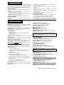
Backup Battery (provides power for at least 4 hours)
Option 1 - 9V, six alkaline AA cells, 1.8 Ah
Option 2 - 7.2 V, six Nickel Cadmium rechargeable AA
cells, 650 mAh
Option 3 - 7.2 V Nickel-Metal rechargeable battery pack,
1300 mAh, supplied by Visonic – to use a non-Visonic
battery pack, its battery snap should have proper polarity!
In Europe: For rechargeable cells, use BYD Battery
Company Ltd. D-AA700A (1,2 V / 700 mAh).
Battery Test: Once every 24 hours, and once per hour
during AC power loss.
2.4 Communication
Built-in Modem: 300 baud, Bell 103 protocol
Data Transfer to Local Computer: Via RS232 serial port
Report Destinations: 2 central stations, 4 private telephones, 1 pager
Reporting Format Options: SIA, Pulse 4/2 1900/1400 Hz,
Pulse 4/2 1800/2300 Hz, Contact ID
Pulse Rate: 10, 20, 33 and 40 pps - programmable
Message to Private Phones: Tone or voice
Message to Pager: PIN No.Alarm Type Zone No.
2.5 Physical Properties
Operating Temp. Range: 32°F to 120°F (0°C to 49°C)
Storage Temp. Range: -4°F to 140°F (-20°C to 60°C)
Humidity: 85% relative humidity, @ 30°C (86°F)
Size: 9-13/16 x 7-1/2 x 1-3/4 in. (250 x 190 x 44 mm).
Weight: 2 pounds (905 g) less batteries
Color: Ivory and charcoal gray
3. INSTALLATION
3.1 Unpacking the Equipment
Open the cardboard packing box and check whether all
items have been included. If you find out that an item is
missing, contact your vendor or dealer immediately.
3.2 Supplying Power to the Unit
Enrolling the transmitting devices’ ID codes in the PowerMax memory will be easier if carried out before actual
installation, with all detectors and the control panel on a
work bench. It is therefore necessary to power up the
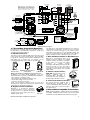
PowerMax temporarily from the external power transformer or from its backup battery (see figure 1).
Disregard any “trouble” indications pertaining to lack of
battery or lack of telephone line connection.
Program the system now as instructed in the
PowerMax programming Guide (Publication DE5450P).
3.4 Mounting
Mounting process is shown in figure 3.
3.5 Wiring
All terminals and connectors are accessible within the
opening at the back of the PowerMax. All screw terminal
blocks can be pulled out, wired appropriately and plugged
back in.
WARNING! When plugging terminals back
into place, be sure to align them carefully
with the pins on the PCB. Mis-aligned or
reverse insertion of terminals may damage
internal PowerMax circuits!
The telephone-type connectors are also easy to deal with,
because of their quick attach/detach capability.
1
Remove battery area
cover (see figu re 2,
steps 1-3), remove screw
and remove battery lid.
6-TERMINAL
TEL. LINE
SOCKET
TOP
WIRING
CHANNEL
PGM OUT &
ZONE 30 INPUT
TERMINALS
2
BAT
3
S et b a tt e r y t yp e
jumper position:
For alkaline (dry)
batteries, set jumper
in DRY pos it io n.
Fo r rech argeable
batteries set jumper
in CHRG position
(as shown).
Insert 7.2V battery pack (optional) to the battery holder
(to use non-original battery pack, its battery snap should
have proper polarity), or insert 6 battery cells.
Figure 1. Backup Battery Insertion
CAUTION! Verify that the jumper is at the
correct position for the actual battery cells
being installed.
3.3 Programming
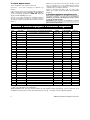
It is recommended to plan ahead - use the tables in
appendices A and B at the end of this guide to register the
intended location of each detector, the holder and
assignment of each transmitter and the control plan for the
X-10 units.
Gather up all transmitters and detectors used in the
system and mark each one in accordance with your
deployment plan.
DE5450 PowerMax Installation Instructions
REAR
OPENING
POWER IN &
SOUNDER OUT
TERMINALS
COM+
INT EXT -
LATERAL
WIRING
CHANNEL
LATERAL
WIRING
CHANNEL
0.5A
SOUNDER
FUSE
BOTTOM
WIRING
CHANNEL
4-TERMINAL SOCKET
FOR X-10
CONTROLLER
Figure 2. Sunken Wiring Area Layout
3.6 Connecting the AC Transformer
CAUTION! Do not plug the transformer into the AC
outlet before completing all other wiring.
A. U.S.A. only: Remove the center screw from the AC wall
outlet.
B. Plug the transformer directly in - the Power LED of the
control panel should illuminate.
C. U.S.A. only: Use the screw removed in Step A above
to secure the transformer to the AC outlet. Tighten the
screw well.
D. The distance of the transformer from the system should
not exceed 150 ft using 18 AWG conductors.
3