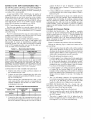
1
AXiS
TM
42KC, 45UC, 45XC, 35BF
Access Floor Terminal Units
Installation, Operation and
Configuration Instructions
CONTENTS
Page
SAFETY CONSIDERATIONS ......................
1
GENERAL ......................................
2-5
System Overview ................................
2
System Architecture .............................
3
PRE-INSTALLATION ..............................
6
Unpack and Inspect Units ........................
6
Storage and Handling ............................
6
Prepare Jobsite for Unit Installation ..............
6
45XC FAN-POWERED ZONE MIXING UNIT
INSTALLATION ..............................
6-27
45XC Hardware ...................................
7
45XC Field-Supplied
Hardware ...................
7
45XC Fan-Powered Zone Mixing Box
Installation .....................................
9
45XC Sensor Installation ........................
14
45XC Input and Output Connectors .............
25
Connect to the CCN Communication
Bus .......
26
Connect Air Pressure Tubing ....................
26
45UC UNDERFLOOR SERIES FAN-POWERED
TERMINAL INSTALLATION .................
27-35
45UC Hardware ..................................
27
45UC Field-Supplied Hardware ..................
27
45UC Underfloor Series Fan-Powered Unit
Installation ....................................
29
45UC Sensor Installation ........................
30
Connect to the CCN Communication
Bus .......
30
Modulating Baseboard Hydronic Heating ........
35
42KC PERIMETER FAN COIL UNIT
INSTALLATION .............................
36-45
42KC Hardware ..................................
36
42KC Field-Supplied Hardware ..................
37
42KC Perimeter Fan Coil Unit Installation
.......
37
Connect the Power Transformer .................
38
Fan Coil Controller Inputs and Outputs .........
44
42KC Sensor Installation ........................
44
35BF DIFFUSER INSTALLATION ..............
46-49
35BF-R Swirl Diffuser Installation ...............
46
35BF-CT, D,V Linear Diffuser Installation .........
46
OPERATION ..................................
50,51
Initial Start-Up Procedures ......................
50
45XC Start-Up and Checkout Procedure .........
50
42KC Start-Up ...................................
50
Manufacturer
CONFIGURATION
45xc Commissioning
Printed in U.S.A,
...........................
51
45XC Set-Up and Configuration
.................
42KC Set-Up and Configuration
.................
42KC Fan Coil Airflow Adjustment
..............
Setting Fan Airflow with ECM ...................
Balancing
Underfloor Fan Terminals
............
Speed Controller ................................
Set Points .......................................
Testing and Start-Up ............................
45XC Operation
.................................
42KC Fan Coil Sequence ........................
45XC Application Considerations
...............
Maintenance
...................................
SAFETY
51
57
57
57
57
6O
6O
61
62
66
66
67
CONSIDERATIONS
SAFETY
NOTE
Air-handling
equipment will provide safe and reliable
service when operated within design specifications.
The
equipment
should be operated
and serviced only by
authorized
personnel who have a thorough
knowledge
of system operation,
safety devices
and emergency
procedures.
Good judgement should be used in applying any manufacturer's
instructions
to avoid injury to pel.sonnel or
&tmage to equipment and propel_y.
Disconnect all power to the unit before performing maintenance or service. Unit may automatically start if power is
not disconnected.
Electrical shock and personal injury
could result.
If it is necesstu-y to remove and dispose of mercury contactors in electric heat section, follow all loc_d, state, and federal laws reg_uding disposal of equipment
containing
hazardous materi_d s.
reserves the right to discontinue, or change at any time, specifications
Catalog No. 04-53450001-01
Page
51-68
............................
or designs
Form 45-4SI
without notice and without incurring obligations.
Pg 1
11-05
Replaces:
45-2SI
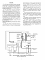
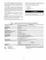
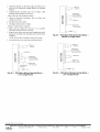
GENERAL
pressure between 0.01 and 1.0 in. wg and to control and maintain space temperature by measuring both plenum and space
tempel_tture. The space temperature set point may be adjusted
by the user through the space temperature sensor without additional software.
The 45XC fan-powered mixing box provides plenum pressure and temperature control to the undedloor plenum. The
45XC mixing box is also equipped with a modulating prima U
air damper and a variable speed fan. Together. these features
allow the 45XC unit to maintain plenum pressure at the desired
pressure set point while adjusting the plenum temperature to
match the load requilements.
The 45UC series underfloor fan-poweled terminal and the
42KC fan coil unit are used to provide increased cooling or
supplemental heating to perimeter zones. These units are available with factou-installed
electric or hot water heating coils.
The controllers are factou-mountedi
The 33ZCPLNCTL
zone controller is supplied on the 45XC fan-powered mixing
box. The 33ZCFANTRM
underfloor controller is supplied on
the 45UC underfloor fan-powered terminal. The 42KC fan coil
units contain the 33ZCFANCOL
perimeter fan coil controllel:
All tue designed to be an integral part of the Carrier Direct Digital Controls (DDC) system. The controllers can communicate
on the Carrier Comfort Network® (CCN) system while completely integrating with the building's heating, ventilation and
air conditioning (HVAC) system.
Each 45XC zone controller also has the ability to function
as a linkage coordinator for systems with up to 128 zones. As a
linkage coordinatol, a controller retrieves and provides system
information
to the air-handling
equipment
and other zone
controllers. When a primtu-y supply air sensor is installed, the
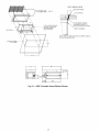
controller can function as a stand-alone device. See Fig. 1
and 2.
The controller monitors differential pressure from two pressure probes: one mounted in the space and one in the pressurized plenum. It compares file resulting signal to a plenum
pressure set point in order to provide pressure-independent
control of the air passing through the mixing box into the
plenum.
The controller is wired to a w_dl-mounted, field-supplied,
space temperature
sensor (SPT) in order to monitor zone
temperature changes and satisfy zone demand.
The controller is designed to allow a service person or
building owner to configure and operate the unit through the
CCN user interface, however, a user interface is not required
for day-to-day operation. All maintenance, configuration, setup, and diagnostic information is available through the Level II
communications
port to _dlow data access by an attached computer running Network Service Tool, ComfortVIEW TM, or
ComfortWORKS®
sollware.
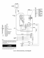
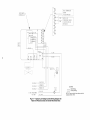
System
Overview
-- Electronic control units feature a
factory-installed
enclosure that provides easy access for field
connections.
The 45XC zone controller is factory-supplied
and factoryconfigured, and consists of a processol, pressure transducer and
actuatol: The controllers are configured to maintain the plenum
PRIMARY
AIR DUCT
PRIMARY
/ RETURN
FIELD-SUPPLIED
PLENUM AIR
TEMPERATURE
PRIMARY AIR
FILTER
MONITOR
i R
SENSOR _
PRESSURE
AIRFLOW
SENSOR_.
_
PRIMARY AIR
DAMPER
_[
SWITCH
(fieH-suppUed)
m
II
Ii
_- -T,,T,,l)
........
'_
-----RETURN
DUCT
DAMPER _
ACTUATOR
FAN MOTOR
I
UNDERFLOOR
..'i
ZONE CONTROLLER
(3 3ZCPLNCTL)
*....
g
m
•
•
• CONTROLS
HIGH
PORT
LOW
PORT II
•
r_
•
•
•
3 equivalent
SPACE
PRESSURE
SENSOR
m
/stra _(_idn
[s_ha_ge duct
MIXED AIR
_
UNDERFLOOR
PLENUM
diameters
ENCLOSURE
=
TEMPEI::_STPA_ITI
SENSOR _
I--
PLENUM PRESSURE SENSOR
•_"
m
SUPPLYAIR
TEMPERATURE
Fig. 1 -- Typical Installation of Single 45X0 Fan-Powered Mixing Unit
for Each Underfloor Zone
PRIMARY
AIR DUCT
/ RETURN
PLENUM AIR
PRIMARY AIR
TEMPERATURE
FIELD-SUPPLIED
FILTER
MONITOR
PRESSURE
: (f _1_ _upplj_)
AIRFLOW
:
SWITCH
(field-supplied)
II
I
t
PRIMARY AIR
DAMPER
DUCT
ACTUATOR
FAN MOTOR
INTERFACE
l
HIGH
PORT
UNDERFLOORZOBECONTROLLER
(33ZCPLNCTL)
LOW
PORT
CONTROLS
ENCLOSURE
FIELD-INSTALLED
(Airflow
in applicalions
(used
SPACE
TEMPERATURE
SENSOR
45XC
unit
presstlrizing
VELOCITY
than one
a common
plenum)
UNDERFLOOR
PLENUM
3 equivalent
PROBE
Sensor)
with more
diameters
e duct
(minimum)
SUPPLY AIR
TEN PERATURE
Fig. 2 -- Typical Installation for Multiple 45X0 Fan-Powered Mixing Units
in a Larger Common Underfloor Zone (One 45XC Unit Shown)
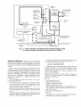
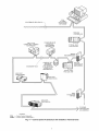
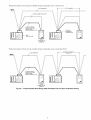
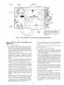
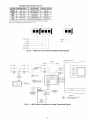
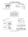
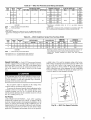
System
Architecture--Figure
3 shows the typical
control system architectme: a 45XC mixing box unit used to
provide the mtdn plenum plessure and temperature control and
four 42KC fan coil units to provide supplemental heating and
cooling.
Figure
controllers
of a large
same bus,
the needs
perimeter
age, with
configured
4 shows an tmangement
of underfloor and zone
and temfinal units employed in the HVAC system
building. Though all controllers are connected to the
controllers am configured to stand alone, satisfying
of individu_fl zones. These tue commonly used in
zones. All underfloor controllers participate in linkone configured as a linkage master; the rest are
as slaves.
This arrangement,
from the software
the following information:
point of view, gives
A bridge is lecommended
to isolate the underfloor control
system from the primary communication
(comm) bus to:
• improve communication
quality
• increase communication
speed
Controllers use the underfloor plenum as the air source and
control the diffusels to satisfy the space temperature needs.
Controllel_ also make use of strip heaters for auxiliary heating.
POWER REQUIREMENTS
_+10% at 40 va (50/60 Hz).
WIRING CONNECTIONS--Field
wiring is 18-gage to
22-gage wire. The zone controller is a NEC (Natiomd Electric_d
Code) Class 2 rated device.
INPUTS
•
All controllers may be configured to stand _flone with flleir
own sensor OR they may shtu'e a temperature
sensor
between themselves.
The zone controllers do not share
sensor data wifll underfloor controllers.
•
•
•
•
•
•
Controllers may have their own temperature sensor (located
near ceiling plenum) OR may share a single temperature
sensoE
Controllers p_uticipate in linkage when sending the damper
position, occupancy, zone temperature and temperature set
point <a to the master underfloor controllel:
•
•
•
-- The power supply is 24 vac
space temperatme sensor
primary air &mper position
plenum sensor (factory-installed)
supply air temperature sensor
optiomd primary air temperature sensor (required for systems which do not utilize a linkage compatible air source)
• optional CO 2 sensor
• optiomd relative humidity sensor
OUTPUTS
internally factory-wired
internally factory-wired
VAV (vtuiable air volume) actuator
fan speed controller
ACCURACY
--
Terminal
tdrflow
pressure
control
is rated
to
1 in. wg measured
maximum
pressure.
Tile zone controller
is
capable of controlling
from as low as 0.01 in. wg to as high as
1.0 in. wg nominal
pressure
with an accuracy
of _+3% (nomimfl) at any point within the range.
HARDWARE
(MEMORY)
FLASH
EPROM
memory.
DIFFERENTIAL
--
PRESSURE
0.0 to 2.0 in. wg maximum
SPECIFIED
The
hmdware
SENSOR
--Pressure
for the onboard
SENSING
consists
TEMPERATURE
of
range
pressure
is
sensol:
RANGE
--
The
controller
space temperature
measuring
range is -40 to 245 E
This range applies
to space temperature,
supply-air
temperaturn and pfimtu'y air temperature
sensors.
The controller
has an
allowable
control set point
and 45 to 99 F for cooling.
COMMUNICATIONS
range
--
from
40 to 90 F for heating
The maximum
number
of control-
lets is limited to 128 zones, with a limit of 8 systems
Coordinator
configured
for at least 2 zones). Canier
Network®
(CCN) bus length
morn titan 60 devices on tiny
RS-485 repeaters
am required
At 19,200 and 38,400 baud, the number of controllel_ is
limited to 128 maximum, with no limit on the number of Linkage Coordinators. Bus length may not exceed 1000 ft.
ENVIRONMENTAL
is 32 to 140 F
(non-condensing).
Shipping Temperature
is _4-0 to 185 F fit 0 to 90%
(non-condensing).
PERFORMANCE
VIBRATION
•
•
0.014 in. peak-to-peak displacement
0.75 G measured fit 31 to 300 Hz
CORROSION
APPROVALS
•
•
(Linkage
Comfort
may not exceed 4000 ft, with no
1000 ft section. Optically
isolated
every 1000 ft.
RATINGS -- Operating
Temperature
fit 0 to 90% rh (relative
humidity)
•
--
Equipment
intended
measured
[]
listed under UL 873
conforms
to requirements
per European
Consortium
standards EN50081-1 (CISPR 22, Class B) and EN50082-1
(IEC 801-2, IEC 801-3, and IEC 801-4) for CE mm'k
labeling
UL94-5V plenum rated (housing and actuator)
®
®
®lx ] ®
®
®
"-1-
"'"---1"
I_____
®
I
®
®
®..
®
-1£2J
_- _ _ _l
®
_
®
®
35BF-R
Interior Zones
Exterior Wall ''/''
I
LEGEND
42KC
45XC
T
----
fit 5 to 31 Hz
for indoor use only.
Exterior Zones
®
rh
Perimeter Fan Coil Unit with 33ZCFANCOL Fan Coil Controller
Fan-Powered Zone Mixing Unit with 33ZCPLNCTL Zone Controller
Wall-Mounted Temperature Sensor
35BF-D Linear Diffuser
35BF-R Swirl Diffuser
Fig. 3 -- Typical System Layout (45XC and 42KC)
I]11
CCN
SYSTEM
MONITORING
SOFTWARE
CCN PRIMARY BUS (BUS 0)-_
_j
FAN COIL
CONTROLLER
FULLY CCN
COMPATIBLE CARRIER
AIR HANDLER
CC6400 OR CSAM
EQUIPPED
NON-CARRIER
AIR HANDLER
T_'CAoy_,_t
z
II
BRIDGE
_
lJ
(RECO_
SECONDARY
BUS
(33ZCFANCOL)
(1 OF UP TO 128)
ADDRESSED
SEQUENTIALLY
TYPICAL 42KC
FAN COIL UNIT
45UC UNIT
(33ZCFANTRM)
li
//I tl._4_xc
UN,T
33ZOPLNOTL
DATA
COLLECTION
OPTION
II
42KC UNIT
(33ZCFANCOL)
II
II
II
II
/"
LEGEND
CCN
-CSAM --
Carrier Comfort Network®
Comfort System AiRvlanager
TM
Fig. 4 -- Control System Architecture
with Underfloor
Terminal
Units
TO
OTHER
CONTROLLERS
ON COMM BUS
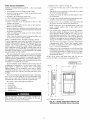
PRE-INSTALLATION
Prepare Jobsite for Unit Installation
Unpack
and Inspect Units -- Remove shipping wlaps
from ;ill units. Check file shipment against shipping ordel:
Inspect for dalnage upon receipt. //shil?ment is damaged or
incomplew, .file claim with transl)ortation company and advi_e
Carrier immediaw@
Storage
and Handling-
Store in a clean, dry and
covered location. Do not stack units. When unpacking units,
ctue should be taken flint the inlet collars and externally mounted components do not become &imaged. Do not lift units using
collars, sensol_, or externally mounted components as handles.
If a unit is supplied with electric or hot water heat, care should
be taken to prevent damage to these devices. Do not lay uncrated units on end or sides. Do not stack uncrated units over 6 ft
high. Do not handle control boxes by tubing connections or
ofl_er external attachments.
-- To savetime
and to reduce the possibility of costly errol_, set up a complete
smnple inst_dlation in a typical room at the jobsite. Check all
critic_d dimensions. Refer to job di'awings and product dimension drawings as required.
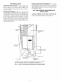
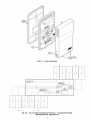
45XC
FAN-POWERED
ZONE MIXING
INSTALLATION
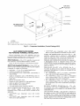
Physical components
of the 45XC fan-powered
zone
mixing unit is detailed in Fig. 5. Figure 6 shows 45XC fanpowered zone mixing unit dimensions and weight data.
PRIMARY
AIR DUCT
CEILING PLENUM
RETURN AIR
DUCT
ENCLOSURE
t
42 in. MINIMUM
54 in. MINIMUM
LOW AND HIGH
PRESSURE PORT*
RAISED FLOOR
UNIT
- SIZE 04
- SIZE 07
SUPPLY AIR
TEMPERATURE
PROBE
*Installation is shown for a single unit in a multiple unit/common plenum application,
High and low pressure ports piped to a discharge plenum. Refer to Fig, 2.
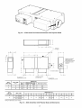
Fig. 5 -- 45XC Fan-Powered Zone Mixing Unit Physical Details
1/2" DIA.
"_
_H_
BC
PER
1
?,
,I
J_
ALLOW AT LEAST
24" CLEARANCE
FOR CONTROLS
[
,
H
6!/4,,
t
t
V-
Y
2[
D
PRIMARY
AIR INLET
L_
[_
_k
1
l
I x..
A
RECIRCULATEB
L
AIR INLET
[_
I" .......
I
I
I
I
I
L -- "T_--_--_"_ --,
I
I
I
I
G
r_
DISCHARGE
Z
.I
k
-- 1-1/4"
_1-1/2"
_B_
RIGHT HAND UNITS AVAILABLE
UNIT WEIGHT
4
7
UNIT
SIZE
2 9/16"
PLAN VIEW - LEFT HAND UNIT
INLETVIEW
45XC UNIT SIZE
1
f_----MOUNTING
BRACKET - (4 PLCS) =
SEE OPTIONAL FEATURES BELOW L
(Ib) l FILTER SIZE (in.)
209
269
FILTER PIN
17 xx 17
22
19 xx 1
1
INLET
SIZE
(in,)
PRI.
FAN
MAX
CFM
CFM*
FLOW
6
8
10
12
500
900
1400
210O
1200
1200
1200
1200
1700
2100
2600
3300
1/2
10
12
14
16
1400
2100
2800
3700
2500
2500
2500
2500
3900
4600
5300
6200
102649-1717
102649-2219
- CONTROLS
I FILTER KIT PIN
I
3503341717
3503342219
DIMENSIONS
HP
Fig. 6 --
45X0
Recirc, Air
A
B
L
W
H
1/2
1/2
1/2
361/8
361/8
361/8
361/8
361/8
361/8
361/8
361/8
181/16
181/16
181/16
181/16
151/8
151/8
151/8
151/8
15
15
15
15
1
1
1
1
421/8
421/8
421/8
421/8
461/8
461/8
461/8
461/8
201/16
201/16
201/16
201/16
201/8
201/8
201/8
201/8
17
17
17
17
*Estimated for rpm/torque controlled motor, at 0.1 in, wg static pressure
NOTE: Inlet Size: 6-10, DD = 37/8 in. Inlet Size: 12-16, DD = 57/8 in,
Fan Powered
DISCHARGE VIEW
NOT SHOWN
D
(in.)
Discharge
F
G
X
Y
Z
J
77/8
97/8
117/8
11
11
11
11
14
14
14
14
9
9
9
9
6
6
7
8
31/8
31/8
31/8
31/8
31/8
31/8
31/8
31/8
97/8
117/8
137/8
157/8
15
15
15
15
17
17
17
17
10
10
10
10
7
8
10
101/4
51/2
51/2
51/2
51/2
41/8
41/8
41/8
41/8
57/8
under floor.
Zone
Mixing
45X0
Hardware -- The 45XC fan-powered mixing unit
contains the 33ZCPLNCTL
zone controlle]:
Figure 7 shows the zone controller physical details,
45X0
Field-Supplied
Hardware -- Each 45XC fanpowered zone mixing unit requires the following field-supplied
components to complete its installation:
• transformer-24 vac, 40 va (stan&ud applications)
• contactors (as required for electric heat)
• V4-in. OD flame retar&mt polyethylene tubing (length not
to exceed 25 ft)
• space temperature sensor (33ZCT55SPT. 33ZCT56SPT. or
33ZCT57SPT)
• supply-air temperature
sensor (33ZCSENSAT)
with two
no. 10 x l/2-in, sheet meted screws (to secure SAT sensor to
supply duct)
• primary-air temperature sensor
• indoor-air quality (CO2) sensor (optional)
• relative humidity sensor (optional)
SPACE TEMPERATURE
SENSOR
(Fig. 8) -Each
33ZCPLNCTL
zone controller
requires
a field-supplied
Carrier space temperature
sensor There are three sensors
available for this application:
• 33ZCT55SPT.
space temperature
sensor with ovemde
button
• 33ZCT56SPT.
space temperature
sensor with ovenide
button and set point adjustment
• 33ZCT57SPT. space temperature sensor with override button, set point adjustment, and manual fan speed control
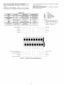
Unit Physical
Data and Dimensions
SUPPLY-AIR TEMPERATURE
(SAT) SENSOR (Fig. 9) -The zone controller must be connected to a field-supplied supply air temperature (SAT) sensor (P/N 33ZCSENSAT) to monitor the temperature of the air delivered by the fan coil.
PRIMARY-AIR
TEMPERATURE
SENSOR
(PAT)
(Optional) --A field-supplied, primtuy air temperature (PAT)
sensor (P/N 33ZCSENPAT) is used on a zone controller that is
functioning as a linkage master for a non CCN/linkage compatible air source. See Fig. 10.
INDOOR-AIR
QUALITY
(CO2) SENSOR (Fig. 11 ) -- An
indoor air quality sensor is required for [AQ monitoring.
Three different CO, sensors are available for zone CO 2 level
monitoring.
• The 33ZCSENCO2
sensor is an indool: wall-mounted sensor with an LED (light-emitting diode) display.
• The 33ZCT55CO2
sensor is an indoor, wall-mounted
sensor without display. The CO, sensor also includes a space
temperature sensor with override button.
• The 33ZCT56CO2
sensor is an indoor, wall-mounted
sensor without display. The CO, sensor also includes a space
temperature sensor with override button and temperature
offset.
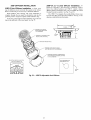
RELATIVE HUMIDITY SENSOR (Fig. 12) -- The
relative
humidity sensor (P/N 33AMSENRHS000)
is an indool: wallmounted sensor and is required for zone humidity control
(dehumidification).
÷24V
...............
_o
FAN
_,
,_
AC
SPT
GND
...........
b.
, _
¢o
RH/IAQ
GND
FA N SECFLOW
_
+IOV
24VAC
SAT
T56
N/A
HEAT3
GND
DMPPOS
GND
.......
PAT
TEST
REMOTE
GND
35 in Ib (4 Nm)
80
110s
J6
O00I_I
Fig. 7 -- 45X0 Fan-Powered Zone Mixing Unit Controller Physical Details (33ZCPLNTCTL)
J
L_
Fig. 8 -- Space
Temperature
L
coo,g w°,_
Sensor
(PIN 33ZCT56SPT
Shown)
.08
.39
FOAM GASKET
.175 DIA
x .600
114"±6
NOTE: Dimensions
are in inches.
Fig. 9 -- Supply Air Temperature Sensor (33ZCSENSAT)
45XC Fan-Powered
STEP
l -- SELECT
Zone Mixing Box Installation
LOCATION
1. Units should be inst_dled so that they do not come in contact with obstacles such as rigid conduit, sprinkler piping,
Greenfield flexible meted covering, or rigid pneumatic
tubing; such contact can transmit vibration to the building
structure, causing objectionable low fiequency noise.
2. Units should never be installed tightly against concrete
slabs or columns, as vibration transmission is amplified in
this condition.
3.
Fig.10--
Primary Air Temperature Sensor
(33ZCSENPAT)
m_
_UUUUUU_
ooooooc
ooooooc
oooooc
oooooc
[
oooo
(12.7)
C
3.25
(8.3)
NOTE: Dimensions
centimeters.
are
in inches.
Dimensions
Fig. 11 -- Indoor Air Quality
(33ZCSENCO2)
(CO2)
in ()
are in
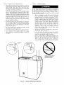
Sensor
Fan-powered
termin_ds require sufficient cletu'ance for
servicing the blowerhnotor assembly from the bottom of
the unit, low voltage controls from the side and line
voltage motor controls or electric heat (if equipped) from
the rear (discharge end) of the unit. See Fig. 6.
Bottom access panel removal requires a minimum of
3-in. minimum clearance, in addition to substantial horizont_d clearance, to slide the access panel out of the way
for service. Actual horizont_d dimensions will vary due to
varying access panels for different sized units. See unit
submitted drawings for detailed information.
NOTE: Be cellain that accommodations
for panel removed of unit casings me large enough to _dlow adequate
internal service room once the panels tu'e removed.
A clemance of 18 in. is recommended for control enclosure access. Unit control enclosure will vary depending
on which control package is used. Control enclosure
location is specified on unit submittals.
Low voltage
enclosure covers _ue removable, not hinged.
A clearance of 36 in. is recommended
for line voltage
motor controls and electric heat control access. High voltage motor controls or electric heat control access is
supplied with hinged access doors for units with fused
disconnect. Specific location is indicated on the unit
submitted.
These recommendations
do not supersede NEC (National
Electrical Code) or local codes that may be applicable.
Adherence to these codes me the responsibility
of the
installing contmctoc
4. Whenever
possible,
fan-powered
boxes should
be
installed over halls or passageways
(rather than over
occupied spaces) in order to limit the sound reaching
occupants.
STEP 2 -- POSITION UNIT
1. When moving boxes, use appropriate material handling
equipment and avoid contact with shaft extensions, controis, wiring, piping, heaters, and control boxes.
2.
Raise unit to position using safe mechanical equipment
and support until hanging means are attached and box is
level.
STEP 3 -- INSTALL
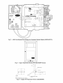
O
Fig. 12-
Wall-Mounted Relative Humidity Sensor
(33AMSENRHS000)
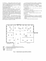
UNIT
1. Inst_dl field-supplied
eyebolts, straphangers or bolt rod
supports as desired. Figure 13 illustrates possible 45XC
unit suspension methods. A typical underfloor installation
is shown in Fig. 14.
2. Care should be taken to use hanging materials of sufficient stiffness and strength, rigidly attached to the unit.
Straps should not be located on coil flanges, electric heat
sections, or control boxes. When using trapeze supports,
avoid areas where access is required to side mounted
controls, or side or bottom access doors. For best installation with trapeze supports, provide elastomeric material
between unit and supports.
3. Hangel.s should be securely attached to bar joist or
mounting anchors properly secured to building structure
with lugs or poured-in-place
hangers. Percussion nails are
not considered adequate anchol.s.
STEP4-- MAKEDUCTCONNECTIONS
1. Check
thatfilepressure
pick-up
in primal"/air
collaris
located
properly
andthatairsupply
ductconnections
tue
airtight.[nst_dl
supplyductwork
on unit inletcollal:
following
_dlaccepted
medium-pressure
ductinstallation
procedures.
Se_d
jointsagainst
leakage.
NOTE:Formaximum
efficiency
incontrolling
radiated
noiseincriticalapplications,
inletductsshould
befabricated
of 24-gage
minimum
sheet
metalin placeof flex
connections.
Flexductisextremely
transparent
toradiatedsound;
consequently
highinletstaticpressure
(Ps)or
sharp
bends
withexcessive
pressure
dropcancause
aradiated
noiseproblem
inthespace.
If flexductisused,
it
should
belimitedtotheconnection
between
thedistributionductandthebootdiffusel:
2. Installthedischarge
duct,beingcareful
nottoreduce
the
faceareaofanyelectric
heatsection
untilseveral
dimnetersawayfromtheunit.It is strongly
recommended
that
lineddischarge
ductbeuseddownstremn
of theunit.
Insulate
ductasrequired.
3. Fanboxesshouldnotbealtached
to octopus
sections
immediately
downstream
oftheunit.
4. Install
optional
leturn-air
filtersbefore
operating
theunit.
5. Leave
construction
filterssupplied
withtheboxin place
untilinstallation
is complete
andbuilding
is clegued
for
occupancy.
STEP 5 -- POWER
WIRING
Disconnect electrical power before wiring or servicing the
unit. All disconnect switches on the temrinal (if equipped)
should be in the OFF position while making power connections. Electrical shock, personal injury, or &_mage to the
zone controller can result.
1. All power wiring must comply with local codes and with
NEC
ANSI/NFPA
(American
National
Sttmdiuds
Institute/National
Fire Protection Association)
70-1981.
Disconnect switches are optional equipment. Electric'M,
control and piping diagrams are shown on the exterior
labeling or on a diagram inside the control and highvoltage enclosure covers, unless otherwise specified in
the order write-up. All units are wired for a single point
electrical connection to the fan and electric heater (if
equipped).
Electric heaters provided by Carrier are
balanced by kW per stage. The installing electrician
should rotate incoming electric service by phase to help
balance overall building load.
2.
All field wiring must be provided
nect per NEC 424-19, 20, and 21.
with a safety discon-
3.
Units with electric heat should use copper wires rated at
least 125% of rating plate amperage. Refer to the unit's
rating label and minimum supply circuit mnps.
4.
Observe wiring diagram and instructions attached to the
unit. A Wye power source with a fourth (neutral) wire in
addition to the full sized ground wire is required for
480-v. 3-phase units. All units must be grounded as
required by NEC 424-14 and 250. See Fig. 15A and 15B.
ROD
HANGER
DO NOTSUSPEND
UNIT BY
TRAPEZE HANGERS THAT
INTERFERE WITH THE
UNITACCESS
PANEL
Fig. 13 -- Typical 45X0 Support
10
Methods
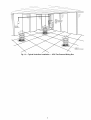
45XC
FAN POWERED
MIXING
BOX
ROOM
SENSOR
SWIRL DIFFUSER
Fig. 14 -- Typical Underfloor Installation -- 45XC Fan-Powered Mixing Box
1!
INLET SENSOR
LLO
POR'f
"tO BE
CAPP_
/
J4
BLU
._IB
LEGEND
AFS
COM
COW
CW
DMPPOS
ECM
GND
N.O.
PAT
SAT
SPT
UL
-------------
Airflow Switch
Common
Counterclockwise
Clockwise
Damper Position
Electronically Commutated Motor
Ground
Normally Open
Primary Air Temperature Sensor
Plenum Temperature Sensor
Space Temperature Sensor
Underwriter's Laboratories
Factory Piping
Factory Wiring
Field Wiring
NOTES:
1. Verify actuator bushing is in the full CW position. Rotate damper CW
to the fully closed position. Mount actuator over damper shaft and
secure to shaft enclosure. Engage clutch and rotate dam )er CCW to
the fully open position.
2. Use insulated quick connects.
Electric shock may result. Disconnect
NEU_t¢
unit prior to servicing unit.
3, These controls have been wired to comply with UL-1995,
Fig. 15A -- 45XC Zone Controller
Wiring -- Control
Package 4840
DISCHARGE
f45XC
SIZE
SENSOR
ASSEMBLY
4 -
35134804
(USES
14" INLET
AIRFLOW
PROBE)
SIZE 7 FIELD NOTE:
35134807
(USES
16" INLET
AIRFLOW
PROBE)
]
/4.5XC
0
0
0
0
0
"_
NMOULNE_I_ICHNAR
GEFESEEN
SFRORoMI
N E_tlSCoH_RuGNE
TDUCTWORK
MOUNT
COIL &:WlRE TIE
OF PNEUMATIC
TUBING IN CONTROL BOX
-
WITH HOLES
OF RED TUBE
FACING
f- c_Z._o_tCT._/AC_ATOR
GREEN/BLAC_
_2_v
,,
SPACE TEMPERATURE
SENSOR
+,o,o_
,,,!
_%ow
SA_
T56
PLENUM
'
TEMPERATURE
-I
PA_
|
L
RED/BLACK
.
I
PRIMARY
(FIELD
GREEN #18
(
11
_
Y
_
INLET SENSOR
_,L
lAIR
FLOW>
GREEN/BLK
(HI) F_
RED/BLK
(" INC >
TO ECM BOARD_
INTERFACE K_ DEC >
(
24
24
VAC_
VAC TRANSFORMER
50VA MIN
HIGH VOLTAGE
CONTROL
-,
/
>
(HI)
RED #18
N.O.
"I
II
SENSOR
SUPPLIED)
j
------------
LEGEND
Airflow Switch
Common
Counterclockwise
Clockwise
Damper Position
Electronically Commutated Motor
Ground
Normally Open
Primary Air Temperature Sensor
Plenum Temperature Sensor
Space Temperature Sensor
Underwriter's Laboratories
Factory Piping
Factory Wiring
Field Wiring
NOTES:
1. Verify actuator bushing is in the full CW position. Rotate damper
CW to the fully closed position. Mount actuator over damper
shaft and secure to shaft enclosure. Engage clutch and rotate
damper CCW to the fully open position.
2. Use insulated quick connects.
COM
C
H
AIR
I
AFS
COM
CCW
CW
DMPPOS
ECM
GND
N.O.
PAT
SAT
SPT
UL
'1"-,_____
_I _I la
SUPPLIED)
TEMPERATURE
"_L #18
"1,.
I
I
SENSOR
(FACTORY
'°'1,I' 1,'*'
"1
!
E%LSU_%'E_DL
_ J
el
DMPPOS O _, _l t ORANGE
'..,J
AIRFLOW,
_
WHT #18
ORANGE
#18
"(EL #18
BLU #18
®
Electric shock may result. Disconnect
unit.
3. These controls have been wired to comply with UL-1995.
BOX
Fig. 15B -- 45XC Zone Controller
unit prior to servicing
Wiring -- Control Package 4841
45XC Sensor
Installation
GENERAL SENSOR
be mounted:
INSTALLATION
Install the sensor as follows (see Fig. 16):
--The
sensor should
1. Locate the two Allen type screws fit file bottom
sensoE
2.
•
•
on tin internal wall near a return air grille or duct
tit least 3 ft from any corner, 2 ft from tin open doorway and
4 to 6 ft from the floor
• proximal to the wiling egress on file wall
• where temperature operating limits ale 32 to 122 F
The sensor should NOT be mounted:
• close to a window, on an outside wall, or next to a door
leading to the outside
• close to or in direct airflow of areas such as open windows,
&'affs or over heat sources
• in meas with poor air circulation, such as behind a door or in
tin alcove where there are dramatic temperature fluctuations
or moistme accumulation
• where it is influenced by supply air as the sensor will give
tin inaccurate leading
• where it may be exposed to direct occupant breathing, such
as near water coolers or coffee machines.
3.
of the
Turn file two screws clockwise to release the cover from
the sensor wall mounting plate.
Lift the cover from the bottom and then release it from
the top fasteners.
4.
Feed the wires from the electrical box through
ing in the center of the sensor mounting plate.
the open-
5.
Using two no. 6-32 x 1 machine screws (provided
the sensor), secure the sensor to the electrical box.
with
NOTE: Sensor may also be mounted directly on the wall
using 2 plastic anchors
and 2 sheet metal screws
(field-supplied).
6.
SPACE TEMPERATURE
SENSOR
INSTALLATION
-A space temperature sensor must be installed for each zone
controllec There are three types of SPT sensors available used
with the 33ZCPLNCTL
controller: 33ZCT55SH'
space temperature sensor with timed override button, 33ZCT56SPT
space temperature sensor with timed override button and set
point adjustment, and 33ZCT57SPT
space temperature sensor
with timed override button, set point adjustment, and manual
fan speed control. See Fig. 8 and 16.
Use 20-gage wire to connect the sensor to the controllel:
The wire is suitable for distances of up to 500 ft. Use a
three-conductor
shielded cable for the sensor and set
point adjustment connections. The stan&_rd CCN communication cable may be used. If the set point adjustment
(slidebm) is not required, then an unshielded, 18-gage or
20-gage, two-conductor, twisted pair cable may be used.
The CCN service jack requires a septuate, shielded CCN
communication
cable. Always
use separate
cables
for CCN communication
trod sensor wiring. (Refer to
Fig. 17-19 for wire terminations.)
7. Replace the cover by inserting the cover at the top of the
mounting pkite first, then swing the cover down over the
lower portion. Rotate the two Allen head screws counterclockwise until the cover is secured to the mounting pkite
and locked in position.
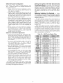
NOTE: Clean sensor with damp cloth only. Do not use
solvents. See Table 1 for resistance vs temperature data.
The space temperature sensor is used to measme the building interior temperature and should be located on an interior
building wall. The sensor wall plate accommodates the NEMA
(National Electrical Manufacturers
Association) standmd 2 x
4 in. junction box. The sensor can be mounted directly on the
wall surface if acceptable by local codes.
CLEARANCE HOLES FOR
(2) #8 MOUNTING
SCREWS ON CENTERLINE
Do not mount the sensor in drafty locations such as near air
conditioning or heating ducts, over heat sources such as baseboard heaters or radiators, or directly above wall-mounted
lighting dimmers. Do not mount the sensor near a window
which may be opened, near a wall corner, or a dool: Sensol.s
mounted in these meas will have inaccurate and erratic sensor
readings.
,
The sensor should be mounted approximately 5 ft from the
floor, in tin area representing the average temperature in the
space. Allow fit least 4 1l between the sensor and any corner
and mount the sensor fit least 2 ft fiom an open doorway.
The sensor consists of the following hardware:
4.50
1 -- sensor top
1 -- sensor base
3.28
1 -- mounting plate
2 -- machine screws (6 x 32)
2 -- locking screws
Before performing service or maintenance operations on
the system, turn off main power switches to the unit.
Electric shock can cause personal injury.
NOTE: Dimensions are in inches.
Fig. 16 -- Space Temperature
Sensor and
Wall-Mounted
Humidity Sensor Mounting
14
The other end of the communication
bus cable must be
connected to the remainder of the CCN communication
bus. If
the cable is installed as a T-tap into the bus, the cable length
cannot exceed 50 ft. No more than 10 T-taps are allowed
per bus. Wire the CCN service jack of the sensor in a daisy
chain arrangement with other equipment. See Fig. 20. Refer to
the Connect to the CCN Communication
Bus section for additiomd details.
Wiring
the Space
Temperature
Sensor
(33ZCT55SPT,
33ZCT56SPT, 33ZCT57SPT)
-- The sensor wiring has the
following requirements:
• Power requirements: 18 to 36 vac RMS 50/60 Hz at 4 va.
• All system wiring must be in compliance with _dl applicable
local and national codes.
• A dedicated power supply is required for this sensoE
• All sensor wiring should be color-coded for ease of maintenance and service.
•
Wiling should be 18 to 22 AWG (American
stranded wire (20 AWG is recommended).
Wire Gage)
\'\
///
To wire the sensor, perform the following (see Fig. 17-19):
CD
1. [dentify which cable is for the sensor wMng.
2. Strip back the jacket from the cables at least 3 inches.
Strip I/4-in. of insulation from each conductoc Cut the
shield and drain wire from the sensor end of the cable.
3. Connect the sensor cable as follows:
a.
b.
c.
d.
e.
f.
Connect
terminal
the wire
block of
2\
one wire from the cable (RED) to the SPT
on the controller. Connect the other end of
to the left terminal on the SEN terminal
the sensor.
signal
wire(s)
(BLACK)
to
4.
Connect the CCN GND sigmd wire(s) (WHITE/CLR)
Termimd 4.
to
RED(+_
_/
',
BLK_GND)
RE-D (SPT)
©
CCN
COM
',j .....
'_;
....
' j ......
SENSOR
WIRING
©©
o
c
\
(/
\:
i"
Fig. 17 -- Space
Temperature
(33ZCT55SPT)
\
\ \
Wiring the CCN Communication
Service Jack
-See
Fig. 17-19. To wire the service jack, perform the following:
1. Strip back the jacket from the CCN communication
cable(s) at least 3 inches. Strip l/4-in, of insulation from
each conductoc Remove the shield and sepm'ate the drain
wire from the cable. Twist together all the shield &'ain
wires and fasten them together using a closed end crimp
lug or a wire nut. Tape off any exposed barn wire to
prevent shorting.
2. Connect the CCN + signal wire(s) (RED) to Terminal 5.
-
_
BLK_-)
-
In the control box, install a no. 10 ring-type crimp
lug on the fan speed wiring shield drain wire.
Install this lug under the mounting screw of the
zone controllec
CCN
_"
, _ WHT(GND),'
\\
[n the control box, install a no. 10 ring-type crimp
lug on the shield drain wire. Install this lug under
the mounting screw of the zone controller.
On 33ZCT56SPT
thermostats,
install a jumper
between the two center terminals (right SEN and
left SET). See Fig. 18.
On
33ZCT57SPT
thermostats,
a
separate
3-conductol;
shielded cable is used to connect the
fan speed wiring. Connect the SPD terminal on the
thermostat to the SPEED terminal on the zone controllec Use the white/clear wire. Connect the COM
terminal on the thermostat to the GND terminal on
the zone controller. Use the black wire. Connect
the 10V terminal on the thermostat
to the +IOV
terminal on the zone controllec
Use the red wire.
Connect
the
Termimd 2.
4',
\_
Connect another wire from the cable (BLACK) to
the GND terminal on the controller. Connect the
other end of the wire to the remaining open terminal on the SEN terminal
block
(COM
on
33ZCT57SPT).
On 33ZCT56SPT
and 33ZCT57SPT
thermostats,
connect the remaining wire (WHITE/CLR)
to the
T56 terminal on the controllec
Connect the other
end of the wire to the SET terminal on the sensor.
3.
s
\
Sensor
Wiring
",.
" -
SEN
WHT_GND)
L'
BLK_-) ',U.
CCN
COM
SET
I@1@1@1@1
w.t
\
{,_J
\
(T56)
,_
SENSOR
WIRING
JUMPER
-_TERMINALS
AS SHOWN
©
Z5
/
Cool
Before wiring the CCN connection, refer to Connect the
CCN Communication
Bus section for communication
bus wiring and cable selection. The cable selected must be identic_d to
the CCN communication
bus wire used for the entire network.
Warm
"\
Fig. 18 -- Space Temperature Sensor Wiring
(33ZCT56SPT)
15
[
CCN COM
I
_
RED (+)
WHITE (SPEED)
\
I WHITE (GND)
/
/
\
I
\
BLACK (-)
\
1
f
\
/
\
k
\
i
3-COND UCTOR
SHIELDED CABLE
X
\
\
r
/
//
\
"
z
SENSOR WIRING
I/
/
/
__
__
__
_(
/
/
_
--
_
]. WHITE(T56_
_ _
m
m
WIRE ACCESS__
HOLE
J
FAN SPEED
CONTROL
SWl
___,.
J2 (RJ11 JACK)
m
U
/
SET POINT
THERMISTOR TEMPERATURE
SENSOR
LEGEND
CCN
SWl
Set Point
----
Carrier Comfort Network@
Switch
Set Point Adjust
NOTE: Do not connect white wire to SET terminal if set point adjustment
is not needed.
Fig. 19 -- Space Temperature Sensor Wiring (33ZCT57SPT)
Table 1 -- Thermistor Resistance vs Temperature Values for Space Temperature
Return-Air Temperature Sensor, and Supply-Air Temperature Sensor
TEMP
(C)
TEMP
(F)
RESISTANCE
0
32
32,851
5
41
25,395
10
50
19,903
15
59
15,714
20
68
12,494
25
77
10,000
30
86
8,056
35
95
6,530
40
104
5,325
45
113
4,367
50
122
3,601
16
--
3-CONDUCTOR
SHIELDED CABLE
--SENSOR
PC
BOARD
RED _SPT)_
-I BLACK(GND)_
/
_z_
/
m
_m
\i
--
/
X
\
SPEED CONTROL
/
/
\
/
I
iRED(+10V)_
/
/
\
/
I
II
\
/
/
BLACK (GND)
(Ohms)
Sensor,
-
Wiring when distance between fan coil controller and space temperature
sensor is 50 feet or less:
CCN COMM BUS
/
50 FT. MAXIMUM
3 COND COMM CABLE (TYP)
2 COND TWISTED
CABLE OR 3 COND
CABLE (TEMP
SENSOR WIRING) (TYP)
t
FAN COIL
CONTROLLER
45KC
FAN COIL UNIT
SPACE
TEMPERATURE
SENSOR
Wiring when distance between
fan coil controller and space temperature
sensor is gleater than 50 feet:
DISTANCE GREATER
THAN 50 FT,
CCN COMM BUS
\
2 COND TWISTED
CABLE OR 3 COND
CABLE (TEMP
SENSOR WIRING) (TYP)
SPACE
TEMPERATURE
SENSOR
Fig. 20 -- Communication
Bus Wiring (42K0 Perimeter Fan Coil Zone Controller
17
Shown)
Table 2
SUPPLY-AIR
TEMPERATURE
(SAT) SENSOR INSTALLATION -- The SAT sensor is required and must be installed
in the fan coil air outlet. The part number is 33ZCSENSAT.
The SAT sensor probe is 6 inches in length. See Fig. 9.
When using a ducted supply, the supply-air temperature
sensor should be located in the supply duct downstream of the
discharge of file fan coil to allow good mixing of the supply
airstream.
See Fig. 21 for mounting
hole requirements.
Disconnect
electrical
lel: Electrical
shock,
controller
can result.
steps to connect
33ZCSENCO2
Wall Mount Sensor (with display)
33ZCT55002
Wall Mount Sensor with 33ZCT55SPT
space temperature sensor (no display)
Wall Mount Sensor with 33ZCT56SPT
space temperature sensor and set point
adjustment (no display)
The CO 2 sensors
listed in Table 3 are factory-set for a range
of 0 to 2000 ppm and a linem voltage output of 0 to 10 vdc.
Refer to the instructions supplied with the CO 2 sensor for
electrical requirements and terminal locations.
To accurately monitor the qu_dity of the air in the conditioned air space, locate the sensor near a return tdr grille (if
present) so it senses the concentration
of CO 2 leaving the
space. The sensor should be mounted in a location to avoid
direct breath contact.
Do not mount the CO2 sensor in drafty areas such as near
supply ducts, open windows, fans, or over heat sources. Allow
at least 3 ft between the sensor and any comer. Avoid mounting
the sensor where it is influenced by the supply air; the sensor
gives inaccurate readings if the supply air is blown directly
onto the sensor or if the supply air does not have a chance
to mix with the room air before it is di'awn into the return
airstream.
the SAT sensor to
SUPPLY
AIR SENSOR
1. Ix)cate the opening in the control box. Pass the sensor
probe through file hole.
2.
Drill or punch
Fig. 22.
a V2-in. hole
3.
Use two field-supplied, self-drilling
sensor probe to the fan coil unit.
Sensor Accessories
DESCRIPTION
33ZCT56002
Do not run sensor or relay wires in the same conduit or
raceway with Class 1 AC service wiring. Do not abrade,
cut, or nick the outer jacket of the cable. Do not pull or
draw cable with a force that may harm the physical or
electrical properiies. Avoid splices in tiny control wiring.
Dmnage to the 33ZCPLNCTL
zone controller can result.
4.
002
location. See Fig. 22 for mounting
power before wiring tile zone contmlpersonal
injury, or damage
to file zone
Perform the following
the zone controller:
--
CO 2 SENSOR
ACCESSORY
PART NUMBERS
SUPPLY
DUCT
TYPICAL
FAN COIL UNIT
1
in the fan coil unit. See
screws to secure the
I
I
I
I
io
Connect the sensor leads to the zone controller's wiring
hmness terminal board at the termimfls labeled SAT
(RED) and GND (BLK).
I
I
I
Perform the following steps if state or local code requires
the use of conduit, or if sensor installation requires a cable
length of more than 8 ft:
1. Secure the probe to the fan coil unit with two
supplied self-drilling screws.
field-
2.
If extending cable length beyond 8 ft, use plenum
20 AWG. twisted pair wire.
rated,
3.
Connect the sensor leads to the zone controller's wiring
hmness terminal board at the termimds labeled SAT
(RED) and GND (BLK).
4.
Neatly bundle and secure excess wire.
I
HC °l
I
I
LEGEND
HC -- Heating Coil
Fig. 21 -- Supply
Mounting
Air Temperature
Location
(42KC)
Sensor
3,00
INDOOR-AIR
QUALITY
(CO2) SENSOR
INSTALLATION -- The indoor-tdr quality (CO2) sensor accessory monitors cmbon dioxide levels, which provide information used to
monitor indoor air quality. Three types of sensors are provided.
The wall sensor can be used to monitor the conditioned air
space. Sensors use infrared technology to measure the levels of
CO 2 present in the all: The wall sensor is available with or
without an LCD readout to display the CO 2 level in ppm. See
Fig. 11.
I
o0.50
CLEARANCE
_ENGAGEMENT
HOLE
HOLE FOR
#10 SHEET METAL SCREW (2)
Fig. 22 -- Supply Air Temperature
Sensor Mounting
Sensor accessory descriptions and part numbers are shown
in Table 2. To mount the sensol: refer to the inst_dlation instructions shipped with the accessory kit.
18
Indoor-Air Quality Sensor WMng -- To wile file sensors
after they are mounted in the conditioned air space or outdoor
location, see Fig. 23 and the instructions shipped with the
sensors. For each sensol; use two 2-conductor
18 AWG
twisted-pair cables (unshielded) to connect the separate isolated 24 vac power source to the sensor and to connect the sensor
to the control board terminals. To connect the sensor to the
control board, identily the positive (0-10 VDC) and ground
(SIG COM) terminals on file sensol: Connect the -10 VDC terminal to terminal [AQ and connect the SIG COM terminal to
terminal GND.
The sensor must be mounted vertically on the wall. The
Carrier logo should be oriented correctly when the sensor is
properly mounted.
DO NOT mount the sensor in drafty areas such as nero heating or air-conditioning ducts, open windows, fans, or over heat
sources such as baseboard heaters, radiators, or wall-mounted
light dimmers. Sensors mounted in those meas will produce
inaccurate leadings.
Avoid comer locations. Allow at least 4 ft between the
sensor and any cornel: Airflow near comers tends to be
reduced, lesulting in em'atic sensor readings.
RELATIVE
HUMIDITY
SENSOR
(WALL-MOUNTED)
INSTALLATION
-- The relative humidity sensor accessory
is installed on an interior wall to measure the relative humidity
of the air within the occupied space. See Fig. 12.
The use of a standard 2 x 4 in. electrical box to accommodate the wiring is recommended for installation. The sensor can
be mounted dilectly on the wall, if acceptable by local codes.
Sensor should be vertically mounted approximately
from the flool: beside the space temperatme sensol:
5 ft up
For distances up to 500 feet, use a 3-conductor.
18 or
20 AWG cable. A CCN communication
cable can be used,
altllough the shield is not required. The shield must be removed
from the sensor end of the cable if this cable is used. See
Fig. 24 for wiring details.
If the sensor is installed directly on a wall surface, install the
humidity sensor using 2 sclews and 2 hollow wall anchors
(field-supplied);
do not orertitqhwn scmm_. See Fig. 16.
The power for the sensor is provided by the control board.
The board provides 24 vdc for the sensor. No addition_d power
source is required.
Do NOT clean or touch the sensing element with chelnical
solvents; they can permanently &unage the sensol:
--3
I
I
24VAC
_311I__LINEVOLTAO
SEPARATE
POWER
SUPPLY
REQUIRED
ii
'O
I _-0
0
[_ czz3
EZZ3
AIR
DAMPER
FRESH
_
VALVE
VALVE
HEAT1
DX_o
oC°_D×_
0
0
24VAC
0
CCNMMUNICATIONS
HEAT2
0
--
--
7
EQUIPMENT
Fig. 23
--
002
Sensor
Wiring
19
(42K0
Controller
Shown)
GROUND
To wire file sensor, perform the following:
5.
1. At the sensol: remove 4-in. of jacket from the cable. Strip
l/4-in, of insulation from each conductoc Route the cable
through the wire clemance opening in the center of the
sensoE
2.
Connect the RED
marked (+).
3.
Install one lead from the resistor (supplied with the sensor) and the WHITE wire into the sensor screw terminal
marked (-). After tightening the screw terminal, test the
connection by pulling gently on the resistor lead.
4.
wire
to the sensor
screw
Connect the remaining
lead flom file resistor
BLACK wile and secure using a field-supplied
end type crimp connector or wire nut.
6.
7.
8.
temrinal
9.
10.
to the
closed
Using electrical tape, insulate any exposed resistor lead to
prevent shorting.
At the control box, remove the jacket from file cable.
Strip 1/4-in. of insulation from each conductoc
Connect file RED wire to terminal 24 VDC on the control
bomd.
NOTE: The 24 VDC terminal is used forrh sensor wiring
only.
Connect the BLACK wire to terminal GND on the
control board.
Connect the WHITE/CLEAR
control board.
wire to terminal RH on the
11. Connect shield to earth ground (if shielded wire is used).
HUMiDiTY
SENSOR
o
o
AiR
FRESH
DAMPER
CCN
COMMUNICATIONS
CCN
COMMUNICATIONS
VALVE
VALVE
DXloCOMo
DX20
HEAT1 24VAC
O
O
HEAT2
O
GROUND
Fig. 24 -- Humidity Sensor Wiring (42K0 Controller Shown)
2O
CO 2 AND
SPACE
TEMPERATURE
SENSORS
(Optional)
NOTE: Them am 2 locking screws provided on the bottom of
file cover for security. A special tool is required to remove and
install the cover if the locking screws gue used.
--
The CO 2 and space temperature
sensors am comprised
of two
sensors
housed
in one unit. They
am designed
to monitor
carbon dioxide
(CO2) levels in the air and measure
the interior
building
temperature.
Two
P/N
models
tu'e
33ZCT56CO2,
available:
which
P/N
33ZCT55CO2,
has a set point
adjustment
The sensor consists of the following
1 -- sensor top
1 -- sensor base
and
potenti-
1 -- mounting plate
2 -- machine screws (6 x 32)
2locking scmws
ometer
Both models
include a push-button
override
that may
be disabled
through
controller
software.
See Table 3 for sensor
specifications.
To convert the CO: sensor into a duct-mounted
CO2 sensok the duct-mounted
need to be pumhased.
aspirator
(33ZCASPCO2)
hardwam:
will
Refer to the instructions
supplied
with the CO 2 sensor for
electrical
requirements
and tenninal
locations.
The
zone
controller
requires
24 vac 25 va transformer
to provide
power
to the sensol:
Before performing service or maintenance
operations on
the system, turn off main power switches to the unit.
Electric shock can cause persomd injury.
should be wall-mounted
in the occupied space to accurately measum the ventilation delivemd to that zone.
I Do
MPORTANT:
CO: in
andthe space
sensor
NOT mount The
the sensor
return temperatum
air duct.
Table 3 -- Performance Specification
(PIN 33ZCT55002
FEATURE
Sensing
SPECIFICATION
Method
Sample
Single Beam Absorption
Infrared
Patented TEMA self calibration software
TM
Range
_+20 ppm
Accuracy
_+100 ppm
60to 90 F: 760 mmHg
Dependency
Response
Warm-Up
0.13% of reading
(15to
32 C)
per mmHg
<2 minutes
Time 0 to 90% Step Change
<2 minutes
Time at 77 F (25 C)
Operating
Conditions
32 to 122 F (0 ° to 50 C)
0 to 99% RH, non-condensing
Storage
Temperatures
-4 to +158 F (-20 to 70 C)
Agency
Certification
FCC Part 15 Class
B/CE/CA
Energy Commission
Calibration/Interval
Lifetime
Power
18-30 vac RMS, 50/60 Hz -- half wave rectified
18-42 VDC polarity protected (dedicated)
1.75 VA maximum
average power
2.75 VA peak power
Analog
CO2 Output
Temperature
Sensor
Temperature
Control
self-calibrating
4-20 mA (Rlmax
10 K_2 Thermistor,
(PIN
33ZCT56CO2
only)
Equipped
after 14 days of run time."
= 500 Ohms)
(dedicated)
and 0-10 V (Source
10 K_2 _+2.5%
Control
Reliability
with a slide potentiometer.
Positions
Resistance
Left (Stop)
0 K (+ 5 K)
Equipped
100 K _+10 K
with a push button that, when depressed,
Meets applicable
Carrier
LEGEND
K_2
RH
RMS
TEMA
-i
i
i
100 mA, Sink 10 mA)
at 77 F (25 C)
Right (Stop)
Override
sensor
0 to 2000 ppm
Sensitivity
Pressure
and 10K temperature
Diffusion
Method
Measurement
and 33ZCT56002)
reliability
shorts
out its internal
thermistor.
requirements
-Automatic
background
calibration
(ABC Logic
is a patented selfcalibration
procedure that is designed to be used in applications
where
CO 2 concentrations
will drop to outdoor ambient conditions
(approximately 400 ppm) at least 3 times in a 14-day period (typically during
unoccupied
periods).
TM)
Kilo-ohm (1000 ohms)
Relative Humidity
Root Mean Square
Time Extended Measurement
21
Step 1 -- Space Temperature
should be mounted:
Sensor
Location
-- Tile sensor
Measure and read the temperature and CO 2 sensor levels by
using a meter or checking the readings at the attached controllet: Be sure the CO 2 levels me above the minimum, up to the
maximum acceptable level in the range.
•
•
on tin internal wall near a return air grille or duct
at least 3 ft from any corner, 2 ft from tin open doorway and
4 to 6 ft from the floor
• proximal to the wiling egress on the wall
• where temperature operating limits ate 32 to 122 F
The sensor should NOT be mounted:
• close to a window, on tin outside w_dl, or next to a door leading to the outside
• close to or in direct airflow of areas such as open windows,
&'arts or over heat sources
• in meas with poor air circulation, such as behind a door or in
tin alcove in meas where there are dialnatic temperature
fluctuations or moisture accumulation
• where it is influenced by supply air as the sensor will give
tin inaccurate reading
• where it may be exposed to direct occupant breathing, such
as near water coolers or coffee machines.
3"
P_
IL
5,25"
Step 2 -- Mounting the Space Temperature
Sensor -sensor can be mounted on a surface, wall or in a junction
See Fig. 25-28.
NOTE: Before mounting the sensor:
into three p_uts. See Fig. 27.
disassemble
The
box.
I
the sensor
Su@_z_ or Wall Mounting
1. Place the mounting pkite on the wall. MaN file desired
location of the two mounting holes on the w_fll through
the holes in the mounting plate. See Fig. 25.
2. Pull the wires through the wire hole in the middle of the
mounting pkite.
3. Drill two mounting holes in the wall in the location
marked in Step 1.
4. Mount the sensor mounting plate with two wood screws
and anchors (field-supplied).
.
Step 3 -- Wiring the Space Temperature Sensor
the following procedure to wire the sensor:
--
WIRE
I]4
i[
Temperature
Plate
3"
Sensor
:1,
Perform
5.25"
LEGEND
1
2
3
4
5
6
the
Once the installation is complete, apply power to the sensor:
A two-minute warm-up will take place. After two minutes, the
LED indicator light will be solid.
-------
3-Pin Terminal Block-Signal Out
3-Pin Terminal Block-- Temp Sensor
3-Pin Terminal Block-- CCN
Wiring Access -- 1.21 in. x ,75 in.
2-Pin Terminal Block-Power In
R J14 Connector-Service Communication
Fig. 26 -- CO 2 and Space Temperature
Sensor Base -- Terminal Connections
22
HOLE
MOUNTING
HOLE
Perform
1. Run the wall wiring through the wire hole in the sensor
base. See Fig. 26.
2. Align the top clips and secure the bottom clips of the
sensor base to the wall mount plate. See Fig. 27.
3. Gently rock the case fiom top to bottom, using minimal
pressure. A "snap" sound will indicate that the sensor is
secure. See Fig. 27.
4. Separate the wires into two bundles. One bundle should
contain the wires for the CO2 sensor 04 and Jl) and the
oilier bundle should contain the wires for the temperature
sensor and CCN 05 and J6). See Table 4 and Fig. 28.
5. Terminate the wires to Jl, J4, J5, and J6. See Table 4 and
Fig. 28.
6. Push excess wire back through the hole. Align the sensor
top over the sensor base.
7. Install the covet on the sensor: Two Allen wrench locking
screws me provided to lock the cover onto the sensor for
security reasons. They are located on the bottom of the
covet: See Fig. 27.
Step 4 -- Space Temperature Sensor St_ut-Up -following procedure to stmt up the sensor:
/I
Fig. 25 -- 002 and Space
Mounting
Junction Box Mounting
1. Run wires through knockout in a 2 x 4 in. junction box
(field-supplied).
2. Pull wires through the wire hole in the middle of the
mounting plate.
3. Secure the sensor mounting plate to the junction box
using the two 6 x 32 machine screws (included).
MOUNTING
HOLE
SENSOR
MOUNTING
PLATE
SENSOR
BASE
SENSOR
COVER
ALLEN WRENCH
LOCKING
SCREWS
(HIDDEN)
Fig. 27 -- Sensor Assembly
J1
1
2
I
I
I
I
i
i
'
1
I
'
I
ISOLATED
24VAC_
OR 24 VDC
POWERSUPPLY
J4
i
I
-
GROUNDED AT
ONE LOCATION ONLY.
CON(-)
I
r
I
I
I
I
I
I
I
I
I
I
I
I
I
I
I
I
I
I
I
I
I
I
I
I
I
I
I
I
I
I
I
I
I
I
I
I
I
I
I
I
I
0
0
0
_ _CNjGAO_N_
CABLE
"_
CCN(_SHIELDED
_ _
TO
TYPICAL
CARRIER
CONTROLLER
SHIELDED CABLE
GROUNDED AT
ONE LOCATI_ONO
©
(5
3
2
J6
_!-NA_
SETPOINT_TS_
COMMON
SENSOR
(5
1
J5
Fig. 28 -- 002
and Space Temperature
(P/N 33ZOT55002,
23
Sensors
-- Typical
33ZOT56002)
Field
Wiring
2
3
I
I
I
I
I
I
I
I
I
I
I
I
I
I
I
I
I
I
I
I
I
I
I
Table 4 -- CO2 and Space Temperature Sensors -- Electrical Connections
(PIN 33ZCT55CO2, 33ZCT56CO2)
CONNECTOR
J1
J3
J4
J5
J6
TERMINAL
3-Pin Terminal Signal Out
1 I 4-20 mA CO2 Output
2 -- Common CO 2 Output
3 1 0-10VDC CO2 Output
3-Pin Terminal Temp Sensor
1 I Thermistor
2 1 Common
31 Temperature Offset
3-Pin Terminal CCN Communications
1 -- CCN (-)
2 1 CCN Ground
3 -- CCN (+)
LEGEND
CCN
i
DESIGNATION
2-Pin Power Terminal
1 I 24VAC (+) (Dedicated Power Supply)
2 1 24VAC (-) (Dedicated Power Supply)
RJ 14 Connector
CCN Service Communication
1 I Not Used
2 1 CCN (+)
3 1 CCN Ground
4 1 Not Used
5 -- CCN (-)
6 1 Not Used
Carrier Comfort Network®
24
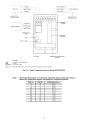
45XC Input and Output Connectors
zone controller
inputs
-- The 45XC
in Fig. 29. Outputs (fan,
are shown
staged heat) me shown in Fig. 30. All available
puts are factoly wiled.
Inputs (J4)
CHANNEL
SPT
d4 PINS (+,-)
4,6
SAT
SP OFFSET
6,8
10, 12
12, 14
RH_AQ
PRIFLO
16 (24 VDC),
15 (+), 13 (-)
9 (10 VDC)
7 (W+), 5 (-)
N/A
REMTCIN
2 (24 VAC), 6 (-)
DMPPOS
PRIMARY
DAMPER
DESCRIPTION
10K Thermistor
100K Potentiometer
10K Thermistor
RH/IAQ Sensor
2-10 VDC
Damper Position
0-10 VDC
Plenum Pressure Sensor
Unoccupied
IAQ
PATEMP
RH
SAT
SP
SPT
CONTROL DEVICE
10K Thermistor
Space Temperature
Supply Air Temperature
-------
Indoor Air Quality
Primary Air Temperature
Relative Humidity
Supply-Air Temperature
Set Point
Space Temperature
NOTE: The 24 v connection
RH sensor only.
0-5 VDC
+10VDC SUPPLY
GROUND
NOT USED
PLENUM PRESSURE
GROUND
GROUND
--
1
3
5
7
9
11
13
RH/IAQ
15
IIIIIIIIIIIIII
IIIIIIIIII
2
4
6
J4
IIIIII
8
10
12
_
+24VDC
PATEMP
SPT
GROUND
GROUND
SAT
T56 SETPOINT OFFSET
Fig. 29 -- 45X0 Input Connectors
LEGEND
Outputs (J5)*
CHANNEL
DMPR
J5 TERMINATIONS
DESCRIPTION
CONTROL
Primary Damper CCW
1,2
CW
2, 3
HEAT ST1
4, 5
Fan 1 (Increase)
24 VAC, 1A
HEAT ST2
5, 6
Fan 1 (Decrease)
24 VAC, 1A
Primary
PRIMARY DAMPER
ACTUATOR(OPEN)
GROUND
24 VAC, 1A
Damper CW
1
--
CCW
CW
DEVICE
COW
DMPR
(J4-16) is required for
0/24 VAC
Override Input
POSITION
REMTCIN/24VAC
out-
LEGEND
Set Point Offset Adjust
Primary Air Temperature
PATEMP
controller
---
Counterclockwise
Clockwise
* All outputs are factory wired.
24 VAC, 1A
2
3
4
J
5
6
I__
HEAT CLOSE/
STAGE 2
COMMON
(24VAC)
HEAT OPEN/
STAGE 1
PRIMARY DAMPER
ACTUATOR (CLOSED)
Fig. 30 -- 45X0 Output
25
Connectors
SUPPLY
Connect
tothe
CCN
Communication
Bus --
connect the Red (+) wire to Termimd 1. Connect the
White (ground) wire to Termimd 2. Connect the Black (-)
wire to Temrinal 3.
All controllers connect to the bus in a d_fisy chain mTangement.
The zone controller may be installed on a prim_wy CCN bus or
on a secondm-y bus fiom file primary CCN bus. Connecting to
a secondaly bus is recommended.
4.
At any baud (9600, 19200, 38400 baud), the number of
controllers is limited to 239 zones maximum. When C_uTier
linkage thermostats are used on the same bus as fan coil units,
no more than 128 fan coils and 12 linkage fllermostats may be
on the same bus. Bus length may not exceed 4000 ft, with no
more than 60 total devices on any 1000 ft section. Optically
isolated RS-485 repeaters are required evel_y 1000 ft.
NOTE: Carrier thermostats
NOTE: The communication
bus diain wires (shield) must be
tied together at each zone controller. If the communication
bus
is entilely within one building, the resulting continuous shield
must be connected to ground at only one single point. If the
communication
bus cable exits from one building and enters
another building, connect the shields to ground at a lightning
suppressor in each building where the cable enters or exits (one
point only).
operate at 9600 band.
The first zone controller in a network connects directly to
the bridge and the others are wired sequentially in a daisy chitin
fashion. Refer to Fig. 20 for an illustration of CCN communication bus wiring.
Connect
MANUFACTURER
Perform the following steps to install and connect the air
pressure tubing:
1. Select a location where the airflow tube will be installed.
The location should be one that is away from the unit's
discharge into the plenum and halfway between that point
and the farthest diffusel: If this requirement is not met,
stable airflow measurements may not be possible.
2. Mount the tubing in the plenum securely.
Cables
2413 or 5463
A22503
8772
02525
3.
Use field-supplied l/4-in, tubing (rated for file application)
to connect the high pressure airflow pickup to barb fitting
PI on the pressure transducel: At the underfloor controllek be careful to avoid sharp bends in the tubing, because
mfdfunctions may occur if the tubing is bent too sharply.
Use fit least 2 fl of tubing for reading stability.
4. Use field-supplied I/4-in. tubing (rated for the application)
to connect the low pressure fitting P2 on the pressme
transducer to file occupied space. Be careful to avoid shmp
bends in the tubing because mfflfunctions may occur if the
tubing is bent too shmply. Use fit least 2 ft of tubing for
stability.
5. The 3/8-in. OD tubing is limited to 25 1lmaximum length
for accurate measurement and response. For lengths up to
50 fi, use l/4-in. OD tubing. Do not exceed 50 ft tube
lengths for either the low or high pressure connections.
CONTROL
PACKAGE 4841 (Fig. 31)-Locate
the airflow probe as shown in Fig. 15B. Perform the following steps
to install and connect the air pressure tubing:
NOTE: Conductors and drain wire must be at least 20 AWG
(American Wire Gage), stranded, and tinned copper. Individual conductors must be insulated with PVC, PVC/nylon, vinyl, Teflon, or
polyethylene. An aluminum/polyester
100% foil shield and an outer
jacket of PVC, PVC/nylon, chrome vinyl, or Teflon with a minimum
operating temperature range of -20 C to 60 C is required.
CONNECTION
TO THE COMMUNICATION
BUS
1. Strip the ends of the red, white, and black conductors
the communication
bus cable.
2.
of
Connect one end of the communication
bus cable to the
bridge communication
port labeled COMM2 (if connecting on a secon&try bus).
When connecting the communication
bus cable, a color
code system for the entire network is recommended
to
simplify installation and checkout. See Table 6 for the
recommended color code.
Table 6 -- Color Code Recommendations
SIGNAL TYPE
+
CCN BUS WIRE
COLOR
Red
PLUG PIN
NUMBER
1
White
Black
2
3
Ground
-
Connect
the other end of the communication
the temrinal
block labeled CCN in the zone
the first air terminal.
Following
the color
bus cable
controller
code
in Table
Tubing
Figure 15A indicates the positions of the two barb fittings.
CABLE PART NO.
Alpha
American
Belden
Columbia
Air Pressure
CONTROL
PACKAGE 4840-The underfloor
controller
measures the pressure differential between the plenum high
and the occupied space low. See Fig. 1. The field-supplied and
field-installed
piping are connected to barb fittings on the
underfloor controller with l/4-in, flame retardant polyethylene
tubing. All piping for this purpose must be plenum rated and
must conform to local codes.
The CCN communication
bus may also connect to the zone
controller space temperatme sensol: Refer to the 45XC Sensor
Instalhnion section for sensor wiring instructions.
COMMUNICATION
BUS WIRE SPECIFICATIONS
-The CCN Communication
Bus wiring is field-supplied
and
field-installed.
It consists of shielded thlee-conductor
cable
with drain (ground) wire. The cable selected must be identical
to the CCN Communication
Bus wire used for the entire network. See Table 5 for recommended cable.
Table 5 -- Recommended
Connect additional zone controllers in a &dsy chain fashion, following the color coded wiring scheme in Table 6.
Refer to Fig. 20.
1. Drill a rectangular
to
of
6,
26
shaped hole in the ductwork.
2.
Securely mount the airflow probe with file high pressure
side (black and red tubing) facing into the airflow fi'om
the 45XC terminal.
3.
The probe is supplied with 10 fl of tubing from the
factory. If required, it may be extended up to 25 fi using
field-supplied I/4 in. OD, flmne retarckmt tubing.
AIR INTO
PLENUM
.*CENTERLINE
bPRESSURE
_PROBE
AIR FROM 45XC
(FacingintoAidlow)
DISCHARGE
PLENUM
TEMPERATURE
SENSOR
LEGEND
Vp --
Velocity Pressure
NOTE: Supply Duct View rotated to show component
location,
Fig. 31 -- Component
45U0 UNDERFLOOR
FAN-POWERED
TERMINAL
Installation
SERIES
INSTALLATION
•
The 45UC underfloor
fan-powered
unit contains the 33ZCFANTRM
underfloor controllel:
the underfloor
controller
physical
33ZCT57SPT,
space
temperature sensor with
button, set point adjustment,
and manu_fl fan speed
monitor
45UC Hardware34 shows
Package 4841)
override
control
SUPPLY-AIR
TEMPERATURE
(SAT) Sensor (Fig. 9) -- The
underlloor
controller
must be connected
to a field-supplied
supply air temperature
(SAT) sensor (P/N 33ZCSENSAT)
to
Physical components
of file 45UC underfloor series fanpowered termimd is detailed in Fig. 32. Figure 33 shows 45UC
underfloor terminal unit dimensions and weight &tta.
Figure
(Control
the temperature
of the air delivered
by the fan coil.
PRIMARY-AIR
TEMPERATIIRE
SENSOR
(PAT) (Optional) -A field-supplied,
primary
air temperature
(PAT) sensor (P/N
33ZCSENPAT)
is used on an underfloor
controller
that is lunctioning as a linkage master for a non CCN/linkage
compatible
air
details.
45U0 Field-Supplied
Hardware -- Each 45UC underfloor fan-powered unit requires the following field-supplied
components to complete its installation:
• transformer-- 24 vac, 40 va (stan&ud applications)
• contactors (as required for electric heat)
• space temperature sensor (33ZCT55SPT. 33ZCT56SPT. or
33ZCT57SPT)
• supply-air temperature sensor (33ZCSENSAT) with two
no. 10 x l/2-in, sheet metal screws (to secure SAT sensor to
supply duct)
• primau-air temperature sensor
• changeover sensor (required for 2-pipe applications)
• indoor-air quality (CO2) sensor (optional)
• relative humidity sensor (optional)
• wtlve and actuator for hot water heat (optional)
SPACE TEMPERATURE SENSOR (Fig. 8) -- Each underfloor controller requires a field-supplied C_urier space
temperature sensol: Them am three sensors available for this
application:
• 33ZCT55SPT. space temperature sensor with ovenide
button
• 33ZCT56SPT. space temperature sensor with override
button and set point adjustment
soume.
See Fig.
INDOOR-AIR
10.
QUALITY
((702)
SENSOR
An indoor _fir quality
sensor is required
monitoring.
Throe different
CO 2 sensors
CO 2 level monitoring.
--
The 33ZCSENCO2
sensor with an LED
•
The
•
sensor
without
display.
The CO 2 sensor
also includes
space temperature
sensor with override
button.
The 33ZCT56CO2
sensor
is an indoor,
wall-mounted
sensor
sensor
without
display.
space temperature
sensor
ture offset.
RELATIVE
HUMIDITY
tive humidity
sensor
wall-mounted
sensor
(dehumidification).
CHANGEOVER
file changeover
an
indoor,
w_fll-mounted
diode) display.
indoor,
wall-mounted
a
The CO 2 sensor
also includes
a
with override
button and temperaSENSOR
(Fig.
12) --The
(P/N 33AMSENRHS000)
and is required
for zone
SENSOR
sensor
is
an
11)
•
33ZCT55CO2
sensor
is
(light-emitting
(Fig.
for indoor air quality
am available
for zone
--
The underfloor
(33ZCSENCHG)
rela-
is an indoor.
humidity
control
controller
in 2-pipe
uses
applications
to determine
if it is capable
of providing
heating or cooling to
file space based on the temperature
of the heating
and cooling
medium
supplied
to the unit from the building
piping system.
This value may be broadcast
to other units.
27
Fig. 32 -- 45UC Series Fan-Powered Underfloor Unit Physical Detail
_67_
_H_
L
_21_6_
1
PRIMARY AIR INLET
7
WITH AeroCross
MULTIPOINT CENTER
o
TM
A/
_I_'NGFLOW
o
c
8
/
F
A _Z
OPTIONALFILTER
ACCESS DOOR
HI-VOLTAGE j
CONTROLENCLOSURE
LO-VOLTAGE
CONTROLENCLOSURE
WEIGHT
45U0
UNIT SIZE
INLET SIZE
(in,)
3
4
Base
Unit
(Ib)
With Hot Water Coil
1-Row
2-Row
With
Electric
9
120
132
136
150
9
128
140
146
158
10
128
140
146
158
45UC
UNIT SIZE
INLET SIZE
3
9-in. Diameter
B
D
14
87/8
9-in. Diameter
14
87/8
12
10-in. Diameter
NOTE: All dimensions
&
97/8
Heat
DIMENSIONS
E
31/2
3
(in.)
F
55/8
L
W
48
21
141/8
48
21
55/8
65/8
are in inches.
Fig. 33 -- 45U0 Underfloor Unit Physical Data and Dimensions
28
H
101/2
DAMPER
ACTUATOR
CLAMP
ASSEMBLY
SHAFT
\
LOW PRESSURE
TUBING ROUTING
/
\
c_
us
MECHANICAL
STOP
GROMMET
\
\
ANTIROTATION
TAB
ACTUATOR
RELEASE
BUTTON
HIGH
PRESSURE
TUBING
ROUTING
NOTE: Actuator clamp accepts dampers
shafts with the following characteristics:
Round -- 1/4-in. to 5/8-in. (6 to 16 ram)
Square -- 1/4-in, to 7/16-ie. (6 to 11 mm)
Damper shaft must be a minimum of 1.5-in.
(38 ram) long.
Fig. 34 -- 45U0 Underfloor Controller Physical Details (33ZCFANTRM)
45UC
Underfloor
Installation
Series
Fan-Powered
Unit
STEP 1 -- POSITION UNIT
I.
2.
Units should be installed under raised access flooring so
that they do not come in contact with obstacles such as
rigid conduit, sprinkler piping, Greenfield flexible metal
covering, or rigid pneumatic tubing; such contact can
tlansmit
vibration to the building structure, causing
objectionable low frequency noise.
4.
Raise unit to position using safe mechanical equipment
and support until hanging means are attached and box is
level.
5.
If necessary, use furring
anchor units to flool:
STEP 2 -- MAKE
strips to level the unit, and
DUCT CONNECTIONS
1. Check that the air supply duct connections are airtight.
Inst_til supply ductwork on unit discharge, following all
accepted medium-pressure
duct inst_dlation procedures.
Seal joints against leakage.
Fan-powered
temrinals require sufficient clealance for
servicing
the blower/motor
assembly,
low voltage
controls from the side and line voltage motor controls or
electric heat (if equipped) from file rear (discharge end) of
the unit.
NOTE: For maximum efl]ciency in controlling radiated
noise in critical applications, inlet ducts should be fabricated of 24-gage minimum sheet metal in place of flex
connections. Flex duct is extremely transpm'ent to radiated sound; consequently high inlet static pressure (Ps) or
sharp bends with excessive pressure diop can cause a radiated noise problem in the space. If flex duct is used, it
should be limited to the connection between the distribution duct and the boot diffusel:
NOTE: Be certain that accommodations
for panel removal of unit casings are large enough to _dlow adequate
internal service room once the panels are removed.
A clearance of 18 in. is recommended for control enclosure access. Unit control enclosure will vary depending
on which control package is used. Control enclosure
location is specified on unit submittals. Ix)w voltage
enclosure covers are removable, not hinged.
A clearance of 36 in. is recommended
for line voltage
motor controls and electric heat control access. High
voltage motor controls or electric heat control access is
supplied with hinged access doors for units with fused
disconnect. Specific location is indicated on tile unit
submittal.
These recommendations
do not supersede NEC (Natiom_l
Electrical Code) or local codes that may be applicable,
which are the responsibility of the installing contractoc
3. When moving boxes, use appropriate material handling
equipment and avoid contact with shaft extensions, controis, wiring, piping, heaters, and control boxes.
29
2.
[nst_dl the discharge duct, being cmeful not to reduce the
face area of any electric heat section until several diameters away from the unit. It is strongly recommended
that
lined discharge duct be used downstream
of the unit.
Insulate duct as required.
3.
Fan boxes should not be attached to octopus
immediately downstream of tile unit.
4.
Protect units from damage caused by jobsite debris. Do
not allow foreign material to fall into unit. Prevent dust
and debris fiom being deposited on motor or fan wheels.
5.
Inst_dl optional return-air filters before operating the unit.
6.
Leave construction filters supplied with the box in place
until installation is complete and building is clemed for
occupancy.
sections
STEP 3 -- POWER
WIRING
2.
3.
Disconnect electric_fl power before wiring or servicing file
unit. All disconnect switches on the terminal (if equipped)
should be in the OFF position while making power connections. Electrical shock, pelNonal injury, or damage to file
zone controller can result.
4.
All power wiring must comply with local codes and with
the NEC (National Electrical Code) ANSI/NFPA (American National Standards Institute/National
File Protection
Association) 70-1981. Disconnect switches are optional
equipment. Electrical, control and piping diagrams are
shown on the exterior labeling or on a diagram inside the
control and high-voltage enclosure covers, unless otherwise specified in the order write-up. All units ale wired
for a single point electrical connection to the fan and
electric heater (if equipped). Electric heaters provided by
Carrier are balanced by kW per stage. The installing
electrician should rotate incoming electric service by
phase to help b¢flance overall building load.
All field wiring must be provided with a safety disconnect per NEC 424-19, 20, and 21.
Units with electric heat should use copper wires rated at
least 125% of rating plate amperage. Refer to the unit's
rating label and minimum supply circuit mnps.
Observe wiring diagram and instructions attached to the
unit. A Wye power source with a fourth (neutral) wire
in addition to the full sized ground wile is requiled for
480-v. 3-phase units. All units must be grounded as
required by NEC 424-14 and 250. See Fig. 35-38.
450C Sensor
Installation
in 45XC Fan-Powered
Connect
-- See Sensor Installation
Zone Mixing Unit Installation.
to the CCN
Communication
Bus --
See Connect to the CCN Communication
Bus section in 45XC
Fan-Powered Zone Mixing Unit Installation.
30
LEGEND
CCN
SPT
TRAN
----
I
Carrier Comfort Network@
Space Temperature Sensor
Transformer
Field Wiring
Factory Wiring
i
FAN
CONTACTOR
I
@
I
I
I
FAN MOTOR
L
LINE
VOLTAGE
I
LOW
12
Ac C>- i
0
,..,J
H F23BJ042
'__-
usE_D
DAMPEI
SECON_
HI
I
I
IBLKI
RE°
IWrit
I
HEAT1
24VAC
O
O
HEAT2
I
_
_
__
O
--
I
TRANSFORMER
GROUND
/7-7
TERMINAL
GROUND
Fig. 35 -- 45UC Underfloor Controller Wiring -- Fan Powered Terminals, Cooling Only
LEGEND
CON
HWV
PAT
SAT
SPT
TRAN
-------
r
/
Carrier Comfort Network®
Hot Water Valve
Primary-Air Temperature Sensor
Supply-Air Temperature Sensor
Space Temperature Sensor
Transformer
Field Wiring
i
I
r
j
i 4
J
I
I
I
4 i
FAN
(_FAN
MOTOR
CON--ACTOR
Factory Wiring
LINE
VOLTAGE
*Required only on Linkage master if on a non-compatible
air source,
LOW
0_-
I
E
--0
_
=
....
i
....
i
0
HF23BJ042
NOT
UsEDO
O
©
NOT USED
CCN
COMMUNICATIONS
HI
CCN
COMMUNICATIONS
I BLKI
REO
IWriT
_4v_c
It LNE
_____A_=N
I
I
TRANSFORMER
l
GROUND
TERMIN_
GROUND
Fig. 36 -- 45U0 Underfloor Controller Wiring -- Fan Powered Terminals, Modulating Hot Water Heat
VOLTAGE
I
I
I
I
i
I
FAN MOTOR
L
....
_
/
\
LINE
VOLTAGE
HF23BJ042
%,0
I
NOT USED
CCN
COMMUNICATIONS
CCN
COMMUNICATIONS
I
-
IBLKI RED I WriT
- 24VACUa]IF
_- _- _- __t_.
--
1
*Required
only on linkage
master
i
if on a non-compatible
air source.
@
I TRANSFQRMER
I
GRQUND
fT7
CCN
T£RMINA_'*I
GR°UNDpAT
SAT
SPT
TRAN
....
--
Fig. 37 J 45UC Underfloor Controller Wiring -- Fan Powered Terminals, Staged Electric Heat
LINE
_ J]_LV_O_LTAG_
E
TRAN LEGEND
---
-----
Carrier Comfort Network®
Heater Relay
Primary-Air Temperature Sensor
Supply-Air Temperature Sensor
Space Temperature Sensor
Transformer
Field Wiring
Factory Wiring
LEGEND
CCN
HWV
SAT
SPT
TRAN
------
\
Carrier Comfort Network®
Hot Water Valve
Supply-Air Temperature Sensor
Space Temperature Sensor
Transformer
Field Wiring
Factory Wiring
/
/t
1
I
FAN MOTOR
FAN
CONTACTOR
LINE
VOLTAGE
7
'11
O-
O
GI
LOW
i
_NAC
iI
_2
O-m
O-OFL 3._1
O
o
0
©
O
NOT USED
HF23BJ042
o
D
HEAT3
©
I
NOT USED
DAMPER
SECOND
_
CCN
COMMUNICATIONS
HI
CCN
COMMUNICATIONS
l
I B'KIREO
IWriT
L 0
.............
- _4vtc
_
L 'IEATI24V H T
I
I
TRA_FORMER
GROUND
TERMINAL
GROUND
Fig. 38 -- 45UC Underfloor
Controller
Wiring -- Fan Powered
Terminals,
Two-Position
Hot Water
Heat
LINE
VOLTAG
E
Modulating
Baseboard
Hydronic
Heating-
For modulating hydronic heating applications, the default
configuration must be changed to properly control the valve.
Refer to the service configuration
table and set the Heating
Ix)op pm'ameters as follows:
Install the water valve on the leaving water end of the basebomd heatel: See Fig. 39. Observe the fluid flow direction
when mounting the valve. Be sure to properly heat sink the
valve and direct the flmne away from the actuator and valve
body when sweating the valve connections. Install the leaving
water temperature
sensor (P/N 33ZCSENCHG)
on the
hydronic heating coil as shown. The sensor accommodates
nominal copper pipe from 1/2 to 1 in. (OD sizes from 5/8 to
11/8 in.). It should be secured to the pipe with the clamp
supplied. If piping is kuger than 1 in. nominal size, a fieldsupplied clamp must be used. Use fiberglass pipe insulation to
insulate the sensor assembly.
Proportional Gain = 20.0
Integral Gain = 0.5
Derivative Gain = 0.0
Start Vgdue = 102.0
Also, set the Ducted Heat decision to YES and set the Maximum Duct Temperature decision equal to 200 E
Refer to Fig. 36 to wire the modulating water valve and the
sensor to the underfloor controllel: Connect the leaving water
temperature sensor to the controller using the wiring connections shown for the SAT sensol:
33ZCSENCHG
(SENSOR)
NOTE: The leaving water temperature sensor replaces the SAT
sensor in this application.
Use 18 or 20 AWG wire for all connections.
The water
valve actuator housing may be used as a junction box if the
leaving water temperatme sensor cable is not long enough and
the sensor cable must be extended to reach the controllel:
1/2"TUBE
3N"TUBE
1"TUBE
Fig. 39 -- Typical Water Valve and
Sensor Installation
35
42KC PERIMETER
FAN COIL
UNIT INSTALLATION
42KC Hardware-
Tile 42KC perimeter tim coil unit
contains tile 33ZCFANCOL zone controllel:
Figure 42 shows tile 42KC perimeter fan coil controller
physical detgdls.
Physical components of tile 42KC fan coil unit is detailed in
Fig. 40. Refer to Fig. 41 for 42KC fan coil unit details.
Fig. 40 -- 42KC Fan Coil Unit Physical Details
TOP VIEW
INLET VIEW
T
DISCHARGE
VIEW
J_
B
Z222222tI25252
INLET SCREEN_
T ..............................
B
........
t-!......
8
_16_
--A-NOTE: All dimensions
L
are in inches.
42KC
UNIT SIZE
INLET SIZE
(in,)
With
Base
Unit
WEIGHT
(Ib)
Hot Water Coil
1-Row
With
2-Row
Electric
Heat
14
12 x 101/2
120
132
136
150
16
14 x 97/8
128
140
146
158
42KC
UNIT SIZE
A
B
C
DIMENSIONS (in.)
E
H
L
W
14
12
101/2
173/4
113/4
14
18
347/8
16
14
97/8
173/4
133/4
16
19
347/8
Fig. 41 -- 42KC Fan Coil Unit Physical
36
Data and Dimensions
c_us
RH
GND
IAQ
FAN ON
LOW
MED
+lOV
SPEED
GND
3ONDSW
on, ,,or-/
Part Number:
33ZCFANCOL
_
=
CNC
GND
; Aoi
DAD ENA=
S/N:
Bus&
Element#:m
Unit#:
J5
Fig. 42 -- 42KC Perimeter Fan Coil Controller Physical Details (33ZCFANCOL)
42KC Field-Supplied
Hardware -- Each 42KC perimeter fan coil unit requires the following field-supplied
components
to complete
INDOOR-AIR QUALITY (CO2) SENSOR -- An indoor-air
quality sensor is required for indoor air quality monitoring.
Three different CO 2 sensors are available for zone CO 2 level
monitoring. One is used to measure CO 2only, while two other
models combine the CO9 sensor with a space temperature sensor to eliminate the need-for multiple sensol,s in each zone.
• The 33ZCSENCO2 sensor is an indool: wall-mounted
sensor with an LED (light-emitting diode) display.
• The 33ZCT55CO2 sensor is an indoor, wall-mounted
sensor without display. The CO 2 sensor also includes a
space temperature sensor with override button.
• The 33ZCT56CO2 sensor is an indoor, wall-mounted sensor without display. The CO2 sensor also includes a space
temperature sensor with ovemde button and temperature
offset.
its installation:
•
•
•
transformer-24 vac, 40 va (stan&ud applications)
contactors (as required for fan or electric heat)
space temperature sensor (33ZCT55SPT, 33ZCT56SPT, or
33ZCT57SPT)
• supply-air temperature
sensor (33ZCSENSAT)
with two
no. 10 x l/2-in, sheet metal screws (to secure SAT sensor to
supply duct)
• changeover sensor (required for 2-pipe applications)
• indoor-air quality (CO2) sensor (optional)
• linkage thermostat (optional)
• relative humidity sensor (optional)
• wtlve and actuator for hot water heat (optional)
SPACE TEMPERATURE
SENSOR -- Each zone controllet requires a field-supplied Carrier space temperature sensor.
There _ue four standard temperature sensors available for this
application:
•
33ZCT55SPT,
button
space
temperature
sensor
with
LINKAGE THERMOSTAT -The linkage thermostat
(33CSKITLST-01) can be used to control multiple 42KC units
fi_m a single thermostat.The linkage thermostat provides thermostat functions for up to 8 units serving a common zone.
Thermostat functions include space temperatme sensing,
remote set point adjustment, and occupancy information. The
linkage themlostat can be used in place of any space temperature sensoE
ovemde
•
33ZCT56SPT,
space temperature
sensor with ovemde
button and set point adjustment
• 33ZCT57SPT,
space temperature
sensor with ovemde
button, set point adjustment, and manual fan speed control
• 33ZC58SPT. space temperature sensor with override button,
set point adjustment, and fan speed control, and LCD
display
SUPPLY-AIR
TEMPERATURE
(SAT) SENSOR
-The
zone controller must be connected to a field-supplied
supplyair temperature (SAT) sensor (P/N 33ZCSENSAT) to monitor
the temperature of the air delivered by the fan coil.
RELATIVE HUM[DITY--The
relative humidity sensor
(P/N 33AMSENRHS000) is an indoor, wall-mounted sensor
and is required for zone humidity control (dehumidification).
42KC Perimeter Fan Coil Unit Installation
STEP
1 -- POSITION
UNIT
1. Units should be installed under raised access flooring so
that they do not come in contact with obstacles such as
rigid conduit, sprinkler piping, Gleenfield flexible metal
covering, or rigid pneumatic tubing; such contact can
transmit vibration to the building structure,
causing
objectionable low frequency noise.
2. Fan-powered
termimfls require sufficient cle_u'ance for
servicing the blower/motor
assembly, low voltage controis from the side and line voltage motor controls or
electric heat, if equipped, from the rear (discharge end) of
the unit. See Fig. 43.
CHANGEOVER
SENSOR -- The 33ZCSENCHG
changeover sensor is used by the 42KC zone controller in 2-pipe
applications to determine the temperature of the medium which
is supplied to the fan coil by the building piping system. The
controller can then determine if it is capable of providing heating or cooling to the space based on sensing the pipe water
temperature. This value may be broadcast to other fan coils if a
linkage thermostat is used or the controller is part of a CCN
system with a comfort controllel:
NOTE: Be certain that accommodations
for panel removed of unit casings gue large enough to allow adequate internal service room once the panels gu'e removed.
37
_1
STEP 4 -- POWER
IN,
AIR FLOW
"
_
i
'
÷
DISCHARGE
€-:
HC
-
"',
-" ="
ALLOW
'
,,?'.',',
FROM
:11
1 IN. CLEARANCE
TOP OF
UN T TO
Disconnect
electrical
power before wiring or servicing
the
unit. All disconnect
switches
on the temrinal
(if equipped)
should be in the OFF position while making
power connections. Electrical
shock, personal
injury, or &image
to the
zone controller
can result.
BOTTOM
OFFLOORING
,; F F, ;TOO,L
DUCT
ELECTRIC
OR HOT WATER
1. All power wiring must comply with local codes and with
the NEC ANSI/NFPA
(American Natiomd Standmds
Institute/National
Fire Protection Association)
70-1981.
Disconnect switches are optional equipment. Electric_d,
control and piping diagrams are shown on the exterior
labeling or on a diagram inside the control and highvoltage enclosure covers, unless otherwise specified in
the order write-up. All units are wired for a single point
electrical connection to the fan and electric heater (if
equipped).
Electric heaters provided by Carrier are
balanced by kW per stage. The installing electrician
should rotate incoming electric service by phase to help
balance overall building load.
Fig. 43 -- Service Clearance for Fan Coil
Unit Installation
A clearance of 18 in. is recommended for contlol enclosure access. Unit control enclosure will valy depending
on which control package is used. Control enclosure
location is specified on unit submittals. Low voltage
enclosure covers are removable, not hinged.
A clearance of 36 in. is recommended
for line voltage
motor controls and electric heat control access. High voltage motor controls or electric heat control access is
supplied with hinged access dool.s for units with fused
disconnect. Specific location is indicated on the unit
submittal.
These recommendations
do not supel.sede NEC (National
Electrical Code) or local codes that may be applicable,
which am the responsibility of file inst_dling contractol:
3.
When moving boxes, use appropriate material handling
equipment and avoid contact with shaft extensions, controis, wiring, piping, heaters, and control boxes.
4.
Raise unit to position using safe mechanical equipment
and support until hanging means tue attached and box is
level.
STEP 2--INSTALL
UNIT-If necessary,
strips to level the unit, and anchor units to flool:
STEP 3 -- MAKE DUCT CONNECTIONS
use
NOTE: For maximum eft]ciency in controlling radiated
noise in critical applications, inlet ducts should be fabricated of 24-gage minimum sheet metal in place of flex
connections. Flex duct is extremely transparent to radiated sound; consequently, high inlet static pressure (Ps)
or sharp bends with excessive pressure &op can cause a
radiated noise problem in the space. If flex duct is used, it
should be limited to the connection between the distribution duct and the boot diffusel:
4.
Protect units from damage caused by jobsite debris. Do
not allow foreign material to fall into unit. Prevent dust
and debris from being deposited on motor or fan wheels.
Install optional return-air filters before operating the unit.
5.
6.
with a safety discon-
3.
Units with electric heat should use copper wires rated at
least 125% of rating plate amperage. Refer to the unit's
rating label and minimum supply circuit mnps.
4.
Observe wiring diagram and instructions attached to the
unit. A Wye power source with a fourih (neutral) wire, in
addition to the lhll-sized ground wire, is required for
480-v, 3-phase units. All units must be grounded as
required by NEC 424-14 and 250.
For zone controllers, the power requirement sizing allows
for a water valves accessory and for the fan contactol: Water
valves tue limited to 10 va on both two-position and modulating hot water. The fan contactor is limited to 3 va (holding) for
each fan output.
NOTE: If a water
extern_d contactors
recommended that a
rating for any single
Install the discharge duct, being careful not to reduce the
face area of any electric heat section until several dimneters away from the unit. It is strongly recommended
that
lined discharge duct be used downstremn
of the unit.
Insulate duct as required.
Fan boxes should not be attached to octopus
immediately downstream of the unit.
All field wiring must be provided
nect per NEC 424-19, 20, and 21.
tho Powor Transtormor
-- An individual,
field-supplied, 24 vac power transformer is required for each
zone controllel: Transfonnel.s must be UL Class 2 rated. Standiud applications require a 24 vac tmnsformel; rated at 40 va
minimum. All transformer
secon&tries tue required to be
grounded. Use only stranded copper conductol.s for all wiring to
the zone controllel: Wiring connections must be made in accordance with NEC and loc_d codes. Ground one side of the transformer secon&uy at the transformer location. Connect the
grounded side of the transformer to J1-2. Connect the hot side of
the transformer secon&uy to J l-l. Connect an 18-gage, green
ground wire from terminal J1-3 to the metal chassis of the unit.
furring
3.
2.
Connoet
1. Check that the air supply duct connections are airtight.
Install supply ductwork on unit discharge, following _fll
accepted medium-plessure
duct installation procedures.
Seal joints against leakage.
2.
WIRING
valve contactor exceeds these limits, or
tue required for electric heat, then it is
60 va transformer be used. The maximum
output is 20 va.
NOTE: Do not run sensor or communication
same conduit with line-voltage wiring.
wiring
in the
NOTE: An accessory conduit box (P/N 33ZCCONBOX)
is available
for conduit wiring connections
to the zone
controller.
sections
Perform
transformer:
the
following
steps
to
connect
the
power
1. Install the field-supplied
transformer
in an electric_d
enclosure that conforms to NEC and local codes.
2.
Leave construction filters supplied with the box in place
until installation is complete and building is cletued for
occupancy.
38
Connect 24 vac from the transformer as shown in the
applicable
wiring diagram (Fig. 44-48). Be sure to
observe polarity when connecting the transformer powec
Term
81o¢k
Or
Opl
L
e
us_
Power
_] 20/277V......
1_
EO_OI__DEs¢
Swl}ch
(Optio_ol)
Supply
Bl_e
lq8
Red _18
n_rol
^
[er
^
v
/
RED I
RED
RED
,..,a
L_
RED
BLACK I12
BROW_ _12
_
FAN
RELAY
_3
RELAY
#2
FAN
BLUE #18
:1
TO Confrol[er
LEGEND
AFS
CAP
COM
DISCN.O.
SCR
o
TO
Control
ler
TO Control
let
Fig. 44 -- Typical 42K0 115/277 V, Single-Phase, 1-Stage, 1-Element Wiring Diagrams for
Fan-Powered Units with Electric Heat
i
-----
Airflow Switch
Capacitor
Common
Disconnect
Normally Open
Electronic Speed Controller
TERM
BLOCK
OR
OPTIONAL
DISC
L
BLACK
SWITCH
RED
OPTIONAL
RED
I::l
USE
COPPER
CONDUCTORS
(PIGTAILS
COME
DISCONNECT
_
_-
_OTOR
_UBE_L_y_
BLACK
08/240V
POWER
SUPPLY
_
BLACK
#_2
#12_
ONLY
WITH
OPTIONAL
SWITCH
ONLY)
TRANSFORMER
WHITE
BLACK
RED
t
(
RED
IscR#2J
24V
#12
RED
L_
BROWN
#12
RED
BLACK
#12
1
]scR #i
#12
4_
FAN
RELAY
FAN
RELAY
#2
RELAY
#_
:Y-d_
c-i
+
BLUE
BLUE
#18
#18
co
o
i
o
v
2
2
v
o
c0
-%
U
3
o
/\
z
LEGEND
m
/\
/
TO LOW
VOLTAGE
CONTROL
/
BOX
Fig. 45 -- Typical 42KC 208/240 V, Single-Phase Wiring Diagrams for
Fan-Powered Units Without Electric Heat
CAP -DISCSCR --
Capacitor
Disconnect
Electronic Speed Controller
+24V
SPT
0
33ZCFANCOL
SAT
/
_i
1
I
SPACE TEMPERATURE
Ji
_
SENSOR
(FIELD SUPPLIED)
BLK
SUPPLY AIR
TEMPERATURE SENSOR
RED
(FACTORY SUPPLIED
HH79NZO74)
r _
T56
CONTROLLER
_
_q
I
GND
PAT
/
J4
N/A
JT_J6
YEL _18
YEL _18
YEL #18
BLU #18
4_
\
e
e
e
\
/
RED #18
IST STAGE HEAT
2@
_
WRITE
STAGE HEAT
_
_
#18
FAN RELAY 3
FAN RELAY 2
FAN RELAY 1
24 VAC TRANSFORMER
75VA MIN
BLACK _18
BROWN _18
LEGEND
ORANGE #18
BLU #18
YEL _18
[_
Q
Fig. 46 -- Typical Low Voltage Control Wiring Diagram for
42KC Fan-Powered Units with Up to 2 Stages of Electric Heat
....
__
Field Wiring
Factory Wiring
NOTE: These controls have been wired to
comply with UL-1995,
÷24V
@
r
SPT
0
33ZCFANCOL
SPACE TEMPERATURE
E SENSOR
I
/
SA_
T56
"-r
BLK
'_
RED
SUPPLY AIR
TEMPERATURE SENSOR
(FACTORY SUPPLIED
HH79NZ074)
CONTROLLER _
GND
GN
PAT
/
J4
"
y
@
N/A
YEL #18
e,
ORA _18
YEL _18
YEL _18
YEL #18
BLU _18
GREEN e18_
FAN RELAY 3
> BLACK #18
FAN RELAY 2
> BROWN #18
FAN RELAY I
>ORANGE #18
24 MAC TRANSFORMER
TBVA MIN
> BLU #18
LEGEND
_]
Q
> YEL #18
47 -- TypicalLow VoltageControlWiring Diagram for
42K0 Fan-Powered Units with On/Off Hot Water Heat
Figi
....
__
Field Wiring
Factory Wiring
NOTE: These controls have been wired to
comply with UL-1995,
+24V
SPACE TEMPERATURE
SENSOR
-r
(FIELD SUPPLIED)
I
E
SPT
0
33ZCFANCOL
CONTROLLER
GN_ _
SAT
T56
4
/
r_ ......
_
BLK
_n
RED
SUPPLYAIR
TEMPERATURE
SENSOR
(FACTORYSUPPLIED
HH79NZO74)
GND
PAT
N/A
YEL _18
ORA _18
YEL _18
YEL #18
BLU N18
4_
GREEN
FAN RELAY 3
> BLACK _18
FAN RELAY 2
> BROWN#18
FAN RELAY I
>ORANGE_18
_18_
24 VAC TRANSFORMER > BLU #18
75VA MIN
> YEL _18
Fig. 48 -- Typical Low Voltage Control Wiring Diagram for
42KC Fan-Powered Units with 3-Point Floating Valve
LEGEND
....
__
Field Wiring
Factory Wiring
NOTE: These controls have been wired to
comply with UL-1995.
Fan Coil Controller
fan coil controller
and 50.
Inputs
and Outputs
inputs and outputs
are shown
--
_q_e
wMng is shown for the linkage thermostat,
al accessory (Fig. 51 ).
in Fig. 49
42KC Sensor
Installation
lation section on page 14.
CONNECT ACCESSORIES
-- Refer to accessory installation instructions for installation procedures. Fan coil controller
--
SPT
SAT
SP OFFSET (T56K57)
CNGOVR
RH
SPEED
IAQ
FS OR REMOTE
DESCRIPTION
J4 PINS/*'-)
14, 12
10, 12
_S
See 45XC Sensor Instal-
LEGEND
Inputs (J4)
CHANNEL
which is an option-
CONTROL
DI
FS
IAQ
RH
SAT
SPT
SIS
DEVICE
10K Thermistor
10K Thermistor
100K Potentiometer
Space Temperature
Supply Air Temperature
8,12
4,6
Set Point Offset Adjust
Changeover Sensor
16 (24 VDC),
15 (+), 13 (-)
7 (+), 5 (=)
RH Sensor
2-10 VDC
Manual Speed Position
0-10 VDC
11 (+), 13 (-)
2 (24 VDC),
J1 Pin 1 (Gnd)
Indoor Air Quality Sensor
Fan Status or
Remote Start/Stop
24 VAC (DI)
10K Thermistor
--------
Direct Input
Fan Status
Indoor Air Quality
Relative Humidity
Supply-Air Temperature
Space Temperature
Start/Stop
NOTES:
1. Terminals 1 and 3 provide switched
24 VAC output power to the load.
2. Terminal 5 connects to field-supplied
24 vac.
3, The 24 v connection
(J4-16) is
required for RH sensor only.
0-10 VDC
MANUALSPEED
NOT USED
GROUND
IAQ
NOT USED
GROUND
GROUND
--
1
3
5
7
9
11
13
RH
15
!l=l=l=l=l=l=l=
J4
i
I=I=1=1=1=1=1=1=
2
FAN STATUS
OR REMOTE
CHANGEOVER
T56SETPOINT
S/S
4
6
8
10
12
14
I
16
F__
+24VDC
SENSOR
SPT
GROUND
GROUND
SAT
OFFSET
Fig. 49 -- 42KC Fan Coil Controller
44
Inputs
SUPPLY
Daughter Board Outputs (J6, J7)
CHANNEL
TERMINATIONS(+,-)
DESCRIPTION
CONTROL
DEVICE
FAN AC
J6-1, J1-1
Fan Input Power
24V, 5A
FAN ON
J6-2, J1-2
Fan Start/Stop*
24V, 5A
LOW
J6-3, J1-2
Low Speed
24V, 5A
MED
J6-4, J1-2
Med Speed
24V, 5A
HI
J6-5, J1-2
High Speed
24V, 5A
CAD
J7-1, J7-2
Outdoor Air Damper
24 VAC 1A
*For single-speed
fan units, connect fan start/stop
to control fan contactor.
NOTE: J6-1 must be jumpered to 24 VAC +. (J1-1).
J7
J6
1
FAN (24VAC)
2
3
5
1
l
--
2
24VAC _
CAD
FAN ON
LO SPEED
MED
SPEED
HIGH
SPEED
Fig. 50 -- 42K0 Fan Coil Controller Daughter Board Outputs
COMMUNICATION
BUS
WIRENUT
SHIELD
(4
t
(+)
(GND)
NIRE WITH
©
©
(+)
SGREEN/wHITE
(GND)
WHITE
(GND)
COOL
t
/
CCN
THERMOSTAT WIRING
CONNECTION
BLOCK -_t
BUSCOMMUNICATION
LINKAGE
FAN COIL UNIT
XXXXXXl
WHT RED
d:C_
24 VAC
TRANSFORMER
(SEPARATE
ISOLATED)
.........
WIRE LENGTH
W-
=
OF 100 FT.
R+
_<___
MAXIMUM
CCN
FCC
---
LEGEND
Carrier Comfort Network@
Fan Coil Controller
POWER
SUPPLY
BOARD
Fig. 51 -- 42K0 Wiring Connections
45
(Linkage
Thermostat Option)
35BF DIFFUSER
INSTALLATION
35BF-CT,
35BF-R Swirl Diffuser Installation
-- Hole openings for diffusers ale pre-cut in the floor panels at the factory.
Removal
D, V Linear
Diffuser
Installation
--
Removal of flooring is not necessary to install the 35BF-D
linem floor diffuser plenum and 35BF-V vmiable volume
diffuser plenum with damper; they can be installed into raised
flooring from the top surface. See Fig. 53 and 54.
of flooring is not necess;uy to install the diffilsers.
Inst;_ll diffusers after flooring and carpet installation
is
complete through the top panel by placing the unit into the
gasketed positive compression quick mount underfloor ring.
The 35BF-CT rectanguku floor grilles/diffuser frame may
be used wifll either of the linem floor diflilseL's. See Fig. 55 for
dimension and deflection information.
Secure the gasketed quick mount underfloor ring to the trim
ring on the underside of file raised panel. See Fig. 52.
_F
THROW DIFFUSER
7 3/4" DIAMETER
""T,LEFLOOR//
FLOW
TRIM RING WITH SPACE FLANGES
(MUST
BE USED WITH THIS ASSEMBLY)
GASKETED
_
/
QUICK
POSITIVE
MOUNTED
COMPRESSION
UNDERFLOOR
RING
10 7/16" DIAMETER
indicator is raised from
trim ring and diffuser
1/4''°/"
(OPTIONAL)
f
Open/Close
1" ._@
CORE
ADJUSTED
REGULATOR
LANGE
9 3/4"
HOLE
core
OPENING
DIFFUSER
FOR
IS 8 5/8"
FLOOR
TILE
Fig. 52 -- 35BF-R Adjustable Swirl Diffuser
46
FIELD INSTALLATION
_DIFFUSER
CORE
FRAME
DIFFUSER
3
( 5BF CT)
rV
_'1
\
DIFFUSER
_/FLOOR
FRAME
PANEL
\
\
\
_""-
ATTACHM ENT
SCREWS
f
ATTACH
DIFFUSER
FRAME
TO 35BF-CT WITH #8 SELF
DRILLING SCREWS.
TALLATION
INTO FLOOR)
35BF-D ASSEMBLY
(FIELD-SUPPLIED)
O K
\
NOTE:
plenum
, \
\ \
\
\
• \
(ASSEMBLED
PRIOR TO
35BF-CT
Diffuser
Frame
and
are sold as separate
units.
35BF-D
\
\
I
8 5/8"
\
ACCESS
FLOORING
(BY OTHERS)
16 _
o
k
8"
°
o
=1
I
1 1/8"
1
Fig. 53 -- 35BF-D Linear Floor Diffuser Plenum
47
FIELD
INSTALLATION
DIFFUSER FRAME
(35BF-CT)
//ff/FLOQR
ATTACH
DIFFUSER
PANEL
(ASSEMBLED
PRIOR T©
INSTALLATION
INTO FLOOR)
FRAME
TO 35BF-V WITH #8 SELF
DRILLING
SCREWS.
35BF-V
(FIELD-SUPPLIED)
ASSEMBLY
\\
\
ACCESS
NOTE: 35BF-CT Diffuser Frame and 35BF-V plenum
are sold as separate units.
FLOORIN_
(BY OTHERS)
8 5/8"
16 I_
8 I_
o
o
o
11 1/2"I
6 _
I
I °
/
1/4"
[] 0
0
I3 1/2'1,
12"
Fig. 54 -- 35BF-V Variable Volume Diffuser Plenum
48
1
35BF-CT
ALUMINUM
--
FIXED
BARS
CT-480 -- 1/4-in. SPACING, 1/8-in. BARS, 0° DEFLECTION
CT-481 --1/4-in. SPACING, 1/8-in. BARS, 15 ° DEFLECTION
CORE WITH HEAVY DUTY MOUNTING
FOR FLOOR APPLICATIONS
FRAME
HEAVY DUTY MOUNTING FRAME
FOR FLOOR APPLICATIONS
Frame Type 5
• 1 in. Flange
Removable core is furnished
with frame. When spring clip
is furnished, add an additional 1/4in. to duct width.
Type 5 heavy duty mounting frame is shown.
NOTE: Core is furnished with additional
11/32" 4
reinforcing,
h
I-,_,
D = Duct SEze
FACE VIEW OF FRAME
/
9 3/8"
\
17 3/8"
AVAILABLE CORES
[]
OVERALL
LENGTH AND WIDTH
Length
Check Selection
1/4 in. Spacing
1/8 in. Bars
Core
//
k
DUCT SIZE MINUS 3/4"
[]
MODEL CT-480
1/4,,F ,/s,,q
•
TTTTTTTT
0 ° DEFLECTION
IIIIIIIII
SUPPORT
MODEL CT-481
1/8"
c
O
15/_2"
BAR
DUCT SIZE
MINUS 3/4"
[]
D
DUCT SIZE
FRAME
TYPE
D
O
CORE
C
5
16
173/8
153/8
•
Width
15 ° DEFLECTION
DUCT SIZE
D
8
Fig. 55 -- 35BF-CT Rectangular Floor Grille
49
1/4 in. SPACING
FRAME
CORE
O
C
93/8
73/8
NUMBER OF
BLADES
29
OPERATION
45XC Start-Up
Start-Up Procedures
-- The 45UC undertloor
fan terminal units and 42KC perimeter fan coil units tue
designed to provide varying quantities of cold primaly air to a
space in response to a thennostat demand for cooling. For a
heating demtmd, the fan will operate to supply ceiling plenum
air to file space or for units equipped with a heating coil, file
heater will operate as required to meet a heating demand.
and Checkout
Procedure
Initial
Before proceeding with start-up, be certain that voltage,
fiequency, and phase correspond
to unit specifications.
Unless noted, all fan motors are 60 Hz, 115, 208/240, or
277 vac electric heat. The electric heat voltage may
exceed the blower motor voltage requirement.
Excessive voltage to the fan box may seriously damage it.
Verify that the DDC (if equipped)
is receiving 24 vac,
-15%, +20%.
The 45XC fan-powered mixing box is designed to provide
airflow to an underfloor plenum at a specified pressure set
point. The air supplied to the plenum is a mixture of primary air
and ceiling plenum air. The fan speed is adjusted automatically
by the control to provide the required airflow to maintain
desired plenum temperature set point while the primary tdr
dmnper will modulate to maintain the desired plenum pressure.
In response to a cooling demand from a thermostat, the damper
will increase the mnount of cold prima U air while the fan
reduces the amount of ceiling plenum air to decrease the temperature of the air being delivered to the space. Typical plenum
design temperatures
tue approximately
62 to 63 E but the
45XC zone controller will automatically adjust the temperature
to meet the load conditions and maintain the balance point.
All underfloor terminal units are shipped with cardboard
packaging rings placed in one side of the blower housing internal to the blower/motor.
These rings are provided to prevent damage to the motor during shipment.
The rings MUST BE REMOVED
prior to operation.
The packing rings are accessible through the terminal's
plenum.
Turn the fan wheel by hand to ensure that
blower is free spinning. Carrier will not accept responsibility for any additional costs for removal of this packaging material. Failure to remove cardboard rings could
result in damage to the unit.
The 45UC underfloor fan terlninal control packages provide
pressure independent operation of the prima U air &tmper.
regardless of changes to the available static pressure in the primary supply. To balance the unit, it is necesstwy to set both the
minimum and maximum airflow set points of this controllel:
The many types of control options available each have specific
procedures required for balancing. Refer to the submittal information for these requirements.
NOTE: The following steps MUST be followed
properly operate and service this unit.
1. Disconnect
Before balancing the system, the air handlers must be operating in accordance with the specifications for air capacity, static pressure, and temperature. The following items MUST be
checked:
in order to
1. All fans must be running fit c;dculated
;dl electrical power to the unit.
tilters
and specified rpm.
2.
Permanent
or tempormy
inst;dled where required.
must
be
clean
and
3.
All central station dampers must be adjusted and operating properly.
All thermostats must be calibrated and fit file desired
settings.
Ftdlure to disconnect the power to the fan box prior to
checking and/or sel-cicing the fan box could result in serious personal injmy.
4.
5.
All ductwoN
2.
Verify that the fan box is inst;flled level and that adequate
mounting support has been provided.
6.
All dirt or loose lining
ductwork.
3.
Remove motor access panel from the bottom of the fan
box, and also remove the control panel covel:
Test the fan motor setscrew. The setscrew should tit
tightly, but it may have loosened during shipment or
installation.
7.
8.
Pumps and sprays, when used, must be in operation.
Connections to the coil, when used, must be checked.
42KC Start-Up-
5.
Rotate the blower by hand to ensure proper
between the blower and the blower housing.
communication
software to stmt up and configure the fan coil
controllel: All set-up and set point configurations are factoryset and field-adjustable.
6.
Check the fan box for loose fiberglass insulation, especially on the electric heater elements or the hot water coils
(if these accessories me inst;flled).
7.
Check the control enclosure
8.
Check the induction inlet filter (if provided) for obstructions, and verify the filter is securely in place.
9.
Verify the main power supply to the connection
box for proper voltage.
4.
10.
12.
must be removed
from inside
9. Water control valve, if used, must be checked.
clearance
Use the Cmrier Comfort Network®
Changes can be made using the ComfortWORKS®
software, ComfollVIEW TM software, or Network Service Tool.
The Network Service Tool is a portable interface device that
allows the user to change system set-up and set points from a
zone sensor or terminal control module. During st;ut-up, the
Cmrier soflwme can also be used to verify communication
with each fan coil controller
and remove tiny debris.
to the fan
For specific operating instructions,
provided with the soflwm'e.
PERFORM SYSTEM CHECK-OUT
Identify the control system supplied.
11. Check all control connections
installation.
must be tight.
(and/or electric) for proper
refer to the literature
1. Check correctness and tightness of all power and communication connections.
Connect electrical power
5O
2.
At the fan coil, check fan and system controls for proper
operation.
3.
At the fan coil, check electrical system and connections
of any optional electric reheat coil. If hot water reheat is
used, check piping and v;dves against job drawings.
4.
Ensure that area tuound
tion dirt and debris.
5.
Check
that
and debris
6.
final
filters
the fan coil is clear
tue installed
can advel5ely
affect
INITIAL
OPERATION
AND
in the fan coil.
system
Verify that the fan coil controller
connected
to the CCN bus.
TEST
of construcDust
If the heat override input is set to Enable, the pressure is
modulated to the greater of the reheat airflow limit or the minimum cooling limit, and full heating is provided. Heating can be
verified by the balancer through the Supply Air Temperature
displayed value. Heating will be controlled during the test to
avoid exceeding the maximum duct temperature. The 45XC
configuration data is displayed in Tables 8-21.
ABNORMAL
CONDITIONS
AND RESPONSES
-- If the
controller is unable to calibrate the open/close potentiometer
readings or zero cfdibrate the pressure transducer during the
commissioning
function of &tmper/transducer
calibration, an
fdtum indication will be set using the CAL point. A CCN alarm
message will also be generated. The ahum condition is cleared
when cfflibmtion is successfully accomplished.
operation.
controls
--
process is repeated except the minimum cooling pressure limit
is used. If a correction is necessary, the control calculates an
offset when the balancer entel_ the correct vfdue.
am
Perform
the
properly
follow-
ing procedure:
1.
Apply
2.
Connect
the service
the controller.
power
3.
Using the service tool, upload the controller
flom addiess
0,1. The ad(kess
may be set fit this time. Make sum that
Service Tool is connected
to this fan coil unit only when
changing
to the unit.
tool to the phone jack
service
port of
the ad&'ess.
CONFIGURATION
45XC
45XC Commissioning-The Commissioning function permits the user to calibrate the &tmper position and zerocalibrate the pressure sensol: Commissioning
is performed
ing points on the maintenance display (see Table 7).
Table
FUNCTION
INPUT
OUTPUT
7 -- Commissioning
CODE
With the primary airflow disabled (AHU OFF), select the
Air Balancing Maintenance screen (ZNAIRBAL) and set
the Commissioning
Mode to ENABLE.
2.
Set the Damper/Transducer
Cal to ENABLE. Allow the
primary air &tmper to fully close. After the controller
calibrates the 0% open primary air damper position, the
controller will fully open the dmnper and calibrate the
100% open primary air damper position. The primaq air
&tmper will fully close to the 0% position and the
controller will zero calibrate the pressure tmnsducel:
When the test is complete, the Damper/Transducer
Cal
point will automatically revert back to DISABLE. Once
this occurs, verify that the Auto-Calibration
point fit the
bottom of the screen reads 'NORMAL.'
If so, the terminal has been calibrated successfully. Force the Commissioning Mode point to DISABLE, then AUTO, which
will remove the 45XC terminal controller from the commissioning mode.
3.
Select the Set Point table (SETPOINT) and configure the
desired Occ Heat set point, which should be set to the
desired space temperature value. If the system (primtuy
air source) is shut down fit night during unoccupied times
and an accelerated morning cool down is desired, configure the Occ Cool set point between 3 and 4 ° F above the
Occ Heat set point. If this cycle is not desired, set the Occ
Cool set point to 99.
4.
In the Set Point table, configure the Unocc Heat set point
and Unocc Cool set point to the same values as the occupied values unless a second space temperature set point is
desired.
us-
DESCRIPTION
Commissioning
CALIBRAT
MAXCOOL
Damper/Transducer
Cal
Maximum Cooling Pressure
MINCOOL
Minimum Cooling Pressure
HEATOVER
COMCFM
Maximum Heating Pressure
Pressure Set Point
MVP
Actual Plenum Pressure
SAT
MODE
Supply Air Temperature
Terminal Mode
CAL
OFFSET
Auto Calibration
Pressure Transducer Calibration
Offset (internal point)
Mode
PROCESS (ALGORITHM)
-- If the Calibration mode is set
to Enable, the controller will interrupt its normal control to provide a means for an air balancer to easily test and commission
the equipment. Once in the Commissioning
mode, the control
will remain in that mode until all tests are completed or for a
maximum of 1 horn: During commissioning,
the POINTS display screen MODE will indicate "COMMISS."
If the Commissioning mode and the Damper/Transducer
are
both set to Enable, the controller will first test and calibrate the
damper to verify the position feedback potentiometer is functioning and internally set the actuator full stroke time. A zero
calibration will also be performed on the pressure tmnsducel: If
either test frills, the CAL (Auto Calibration) output will be set
to alarm. When the test is completed successfully, the control
will reset the Damper/Transducer
Cfdibrate input to Disable.
The control will then provide a method to set, verify and test
the cooling maximum and cooling minimum pressure limits.
While in the Commissioning
mode, if the Maximum Cooling
input is set to Enable, the controller will recover the configured
maximum cooling pressure limit as configured, and display the
value as the pressure set point. If incorrect, the balancer can
enter the correct value in the pressure set point, and this vfflue
will then be transfened back to the maximum cooling configuration limit. The control will then modulate the damper to
achieve this set point and will display the resulting pressure as
the actuffl pressure. If the pressure is incorrect, the balancer can
enter the correct value as the actual pressure and the control
will store this value. Once completed, or if the Minimum Cooling input is set to Enable, the Maximum Cooling input is reset
to Disable. If the Minimum Cooling input is set to Enable, the
5.
51
and Configuration
I.
Function
CMODE
Set-Up
NOTE: Setting the unoccupied space heating set point
lower than normal (below 70 F) consumes additional
energy to maintain this lower temperature set point. The
underfloor system is NOT designed for unoccupied operation fit the terminals, but rather fit file primtuy air source
(AHU or RTU) or through a field-installed zone &imper
to disable primary airflow from the source to the 45XC
mixing terminal. If a lower unoccupied heating set point
is required, configure the Unocc Heat set point to fliat
lower value. The 45XC mixing terminal should be set to
occupied operation fit fill times to ensure maximum system efficiency. Again, if tin accelerated cool down transition is desired, configure the Unocc Cool set point to a
value approximately 4 ° F above the Unocc Heat set point.
When an accelerated cool down transition is not used, the
Unocc Cool set point is configured to 99.
In the Service Config Table (PRESS), configure the Cool
Minimum Plenum Pressure set point, which is used for
normal control.
6.
7.
If the Occ or Unocc Cool set points are used, configure
the Cool Maximum Plenum Pressure set point; otherwise,
set this value equal to the Cool Minimum value. Tile Cool
Maximum value is the controlling plenum plessure set
point used when the space temperature equals or exceeds
the Cool set point. When the space temperature
is
between the heating and cooling set points, the plenum
pressure is controlled to a line+u interpolation between the
two pressure set points.
heating set point. This will prevent overheating of the
space.
NOTE: Only primary air, NOT return air. is used when
the primtuy air source is operating in the heating mode.
The terminal fan will only operate at minimum speed.
The primary tdr damper will modulate as lequired to
maintain the desired heating plenum pressme set point.
Configure the Heat Maximum Plenum Pressure set point.
The controlling plenum plessure set point is used during
morning warm up, when the space temperature falls below the heating set point and the primary air source is
providing heated ail: The value is usually set equal to the
Cool Minimum Plenum Pressure set point in order to
warm the space for occupancy and achieve the heating set
point quickly.
8.
In the Service Config table (PRESS), configme the Heat
Minimum Plenum Pressure set point. This is the plenum
plessure set point used whenever the central station
equipment is in a heating mode, such as Morning Whrm
Up (as detected by the primary air temperatme sensor).
This value should be set lower than the Cool Minimum
Plenum Pressme set point in order to reduce airflow to
this zone when the space temperatme has achieved the
Table 8 -- 45XC Controller Identification Table
TABLE NAME
Device Name
CONTROLLER
ID
ClD_UF
Underfloor Controller
Description
Location
Software Part Number
CESR131317-01
Model Number
Serial Number
WWYYnnnnnn
Reference Number
Version 1.0
LEGEND
CID_UF
--
---
Controller Identification -- Underfloor
Blank Field
Table 9 -- 45XC Points Display Table
POINT
DESCRIPTION
STATUS/UNITS
RANGE
ACCESS
MODE
Terminal Mode
(1)
R
TYPE
Terminal Type
MODE
UNDERFLR
(2)
R
CNTSP
Controlling Set Point
XXX.X F
-40.0-245.0
R
SPT
MVP
Space Temperature
Plenum Pressure
XXX.X F
R/W
R/W
DMPPOS
Damper Position
SAT
Plenum Air Temperature
X.XXX wg
XXX% OPEN
XXX.X F
-40.0-245.0
0.000-2.000
RH
Relative Humidity
AQ
Air Quality (ppm)
PATEMP
REMTCIN
Primary Temperature
Unocc Override
R
RB/V
UNDERFLR
----
0-100
R
-40.0-245.0
R/W
XXX.X%
0.0-100.0
R/W
XXXX
0-5000
R/W
XXX F
-40-245 (3)
Off/On
R/W
R/W
Off
NOTES:
1. Modes = OFF [0], HEAT [1], COOL [5], VENT [3], FAN & VENT
[4], DEHUMID [6], WARM-UP [2], REHEAT [7], PRESSURE [8],
EVAC [9], ZEROCAL [10], COMMISS [11]
2. UNDERFLR is equivalent to CID PAR FAN Type and is fixed for
this application.
3. Used by Linkage Master Zone for Mode determination, if configured as a system and no air source is specified, otherwise spare
temperature sensor.
LEGEND
Read
Read/Write
Underfloor
Table 10 -- 45XC Pressure Set Point Service Configuration
Table
POINT
DESCRIPTION
STATUS/UNITS
RANGE
DEFAULT
COOLMIN
Cool Minimum
X.XX wg
0.00-2.00
0.06
COOLMAX
Cool Maximum
X.XX wg
0.00-2.00
0.08
HEATMIN
DB PCT
Heat Minimum
Deadband
X.XX wg
XX.X%
0.00-2.00
7.5-20.0
0.04
12.5
HEATMAX
Heat Maximum
X.XX wg
0.00-2.00
0.08
52
Table 11 -- 45XC Terminal Service Configuration
DESCRIPTION
POINT
DAMPER PID
Kp
Ki
Proportional
Kd
STARTVAL
Kp
Ki
CW Rotation
STARTVAL
MAXTEMP
DEFAULT
XXX.X
-100.0-100.0
XXX.X
-5.0-5.0
XXX.X
-20.0-20.0
0.0
XXXX.X%
0.0-100.0
10.0
Close/Open
0-1
0 (Close)
30.0
2.5
XXX.X
-100.0-100.0
4.0
Integral Gain
Derivative Gain
XXX.X
-5.0-5.0
0.5
XXX.X
-20.0-20.0
0.0
Start Value
XXXX.X F
XXX F
40.0-125.0
65.0
Proportional
Kd
STATUS/UNITS
I
RANGE
Gain
Integral Gain
Derivative Gain
Start Value
DMPDIR
HEATING PID
I
Table
Gain
Maximum Temperature
SPT Trim
40-200
90
SPTTRIM
XXXX.X
AF
-9.9-9.9
0.0
SATTRIM
SAT Trim
XXXX.X
AF
-9.9-9.9
0.0
0-1
1
RMTCFG
Unocc. Override Configuration
(Close)
Open/Close
LEGEND
SAT
SPT
UNOCC
----
Space Air Temperature
Space Temperature
Unoccupied
Table 12 -- 45X0 Option Service Configuration
POINT
DESCRIPTION
SCH
GSM
Occupancy Schedule #
Global Schedule Master
OVR
Override
SETT
GSTM
(Hours: Minutes)
Set Point Group #
Global Set Point Master
Table
STATUS/UNITS
RANGE
XXX
64-99
DEFAULT
64
No/Yes
0-1
o (No)
XX:XX
00:00-24:00
00:00
XXX
No/Yes
0-16
0
0-1
0-15.0
0 (No)
2.0
BROACK
Broadcast Acknowledger
No/Yes
0-1
0 (No)
SENSOPT
Sensor Options*
XXX
0-2
0
LIMT
XX.X
Maximum Offset Adjust
AF
*0 = None, 1 = Humidity, 2 = IAQ.
Table 13 -- 45X0 Alarm Configuration
POINT
DESCRIPTION
ROUTING
UNOCCUPIED
DEFAULT
XXXXXXXX
XXXX min
XX.X ^F
0-1 each pos
0-1440
1.0-100.0
0 (disabled)
5.0
SPT Occupied
Hysteresis
00000000
SPT
High Limit
Low Limit
HIGHLIM
LOWLIM
HIGHVP
OCCUPIED
RANGE
Alarm Routing Control
Re-alarm Time
RETIME
SPTHYS
Table (Type 10H)
STATUS/UNITS
i
XXX.X F
I
-40.0-245.0
XXX.X wg
F
X.XXX
I
-40.0-245.0
0.000-2.000
40.0
99.0
High Plenum Pressure
0.200
RH
HIGHLIM
LOWLIM
UNOCCUPIED
HIGHLIM
LOWLIM
0.0
i
High Limit
Low Limit
XXX.X%
I
0.0-100.0
100.0
i
High Limit
Low Limit
XXX.X%
I
0.0-100.0
100.0
i
High Limit
Low Limit
XXXX.X
I
0.0-5000.0
1200.0
RH
0.0
AIR QUALITY
LOWLIM
HIGHLIM
250.0
53
Table 14 -- 45XC Linkage Configuration
ZONE
I
PO'NT
LINKAGE
MZENA
NSYSTZ
ASBUSB
ASELEMN
STATIC PRESSURE
I
DESCRIPTION
Table
I
STATUS/UN'TS
RANGE
0-1
1-239
0-239
0-239
I
DEFAULT
Linkage Master Zone
Number of Zones
Air Source Bus Number
Air Source Element Number
No/Yes
XXX
XXX
XXX
0 (No)
1
0
0
MINDP
MAXDP
SPMAX
SPRVAR
CCN-LINKAGE
DATA
Reset Min Damper Position
Reset Max Damper Position
Maximum Reset
SP Reset Variable Name
XX%
XXX%
X.X wg
XXXXXXXX*
0-99
0-100
0.0-5.0
A-Z, 0-9, blank, -,
50
85
0.0
--
CCNVAR
CCNFUNC
DATA RATE
CCN-Variable Name
CCN Function Configt
Data Transfer Rate
XXXXXXXX*
X
XX min
A-Z, 0-9, blank, -,
0-3
1-15
--
CCNOUTP
DESTBUSN
DESTELEN
BRD RECV
CCN Output Point
Destination Bus Number
Destination Element Number
Sensor Mode
1 = Local Sensor
2 = Broadcast
3 = Listen!
XXXXXXXX*
XXX
XXX
X
A-Z, 0-9, blank, -,
0-239
0-239
1-3
--
RESET
SENSCFG
Listen Sensor Config
1 = BPT
2 = BPT & Offset
BRDDEVID
Broadcasting
Element Number
3
10
0
0
1
X
1-2
1
XXX
1-239
1
*ASCII text.
t0 = None
1 = Average
2 = Low
3 = High
Table 15 -- 45XC Set Point Table
DESCRIPTION
POINT
OHSP
Occ Heat
Set Point
STATUS/UNITS
XXX.X F
OCSP
UHSP
UCSP
XXX.X F
XXX.X F
XXX.X F
RANGE
40.0-90.0
DEFAULT
72.0
45.0-99.9
40.0-90.0
45.0-99.9
74.0
72.0
90.0
LEGEND
OCC
OCSP
OHSP
UCSP
UHSP
------
Occupied
Occupied Cool Set Point
Occupied High Set Point
Unoccupied Cool Set Point
Unoccupied High Set Point
Table 16 -- 45XC Zone Linkage Maintenance Table
POINT
ASBUSNUM
ASDEVADR
MZDEVADR
DESCRIPTION
Air Source Bus Number
Air Source Element Number
Master Zone Element Number
STATUS/UNITS
XXX
XXX
XXX
RANGE
----
ASOPMODE
ASTEMP
STRTBIAS
AOHS
Operating Mode
Air Source Supply Temp
Start Bias Time
XXX.X F
XXX min
----
R
R
R
Average Occ Heat Set Point
Average Occ Cool Set Point
Average Unocc Heat Set Point
Average Unocc Cool Set Point
Average Zone Temp
Average Occ Zone Temp
Composite CCN Value
Occupancy Status**
Next Occupied Day
Next Occupied Time
Next Unoccupied Day
Next Unoccupied Time
Previous Unoccupied Day
Previous Unoccupied Time
Maximum Damper Position
Static Press Reset
Pressure Decrease Value
Pressure Increase Value
XXX.X F
XXX.X F
XXX.X F
XXX.X F
XXX,X F
XXX.X F
XXX,X Ft
X
XXX
XX:XX
XXX
XX:XX
XXX
XX:XX
XXXXX.X%
X.X wg
X.XXX wg
X.XXX wg
--------------0.0-100.0
0.0-5.0
0,000-5,000
0,000-5,000
R
R
R
R
R
R
R
R
R
R
R
R
R
R
RAN
RAN
RAN
RAN
AOCS
AUHS
AUCS
AZT
AOZT
CCCNVAL
OCCSTAT
NEXTOCCD
NEXTOCCT
NEXTUNOD
NEXTUNOT
PREVUNOD
PREVUNOT
MAXDMPOS
PRESVAL
PRESDECR
PRESINCR
LEGEND
R
R/W
---
tNo units for this as this is varying in nature and depends on the CCN output
point name in config table.
*'1 =Occupied.
Read
Read/Write
*Modes = OFF [1], COOLING
[6], EVAC [7].
ACCESS
R
R
R
[4], HEATING [3], FREECOOL
[5], PRESSURE
54
Table 17 -- 45XC Zone Maintenance Table
POINT
DESCRIPTION
ZONE OCC
DAVCTL
Occupied
No/Yes
R
Linkage Slave
No/Yes
R
Linkage Master
Timed Override in Effect
No/Yes
No/Yes
R
R
T56OFF
Set Point Offset (T-56)
XXX.X ^F
-20.0-20.0
R/W
CCMR
PPREF
Cool Master Reference
XXX.X F
45.0-99.9
R/W
X.XXX wg
Ena/Disa
0-2.000
HEATENA
Plenum Pressure Reference
Fan Enable
R/W
R
HCMR
Fan Master Reference
XXX.X F
40.0-90.0
R/W
HSMR
0-200
R/W
LINKMAST
TIMOV
STATUS/UNITS
RANGE
ACCESS
Plenum Temperature Reference
XXX F
TCA
COOLFLAG
Temperature Control Airflow
XXX%
R
Cooling in Effect
No/Yes
R
HEATFLAG
Heating in Effect
No/Yes
R
LEGEND
R
-- Read
R/W -- Read/Write
Table 18 -- 45XC Air Balancing Maintenance Table
POINT
DESCRIPTION
CMODE
CALIBRAT
Commissioning
STATUS/UNITS
RANGE
ACCESS
DIS/ENA
0-1
R/W
DIS/ENA
0-1
R/W
Mode
Damper/Transducer
Cal
MAXCOOL
Max Cooling Pressure
DIS/ENA
0-1
R/W
MINCOOL
Min Cooling Pressure
DIS/ENA
0-1
R/W
HEATOVER
Max Heating Pressure
DIS/ENA
0-1
R/W
CONCFM
Pressure Set Point
X.XX wg
0-2.00
R/W
MVP
SAT
Actual Plenum Pressure
X.XXX wg
0.000-2.000
R/W
-40.0-245.0
0-1
R/W
R
Supply Air Temperature
Auto Calibration
CAL
DIS/ENA
R
R/W
XXX.X F
NORMAL/ALARM
LEGEND
-- Disable/Enable
-- Read
-- Read/Write
Table 19-
45XC Holiday Configuration
Tables
POINT
DESCRIPTION
STATUS/UNITS
RANGE
DEFAULT VALUE
MONTH
Start Month
XX
1-12
1
DAY
Start Day
Duration
XX
XXX
1-31
0-365
1
DURATION
55
0
Table 20 -- 45X0 Time Schedule
POINT
OVR
Configuration
Table
DESCRIPTION
Manual Override Hours
STATUS/UNITS
X hours
RANGE
0-4
DEFAULT
0
DOW1
Period 1: Day of Week
XXXXXXXX
0/1
l's
OCC1
Period 1: Occupied from
XX:XX
0:00-24:00
0:00
24:00
UNOCC1
Period 1 : Occupied to
XX:XX
0:00-24:00
DOW2
Period 2: Day of Week
XXXXXXXX
0/1
0's
OCC2
UNOCC2
Period 2: Occupied from
XX:XX
0:00-24:00
0:00
Period 2: Occupied to
XX:XX
0:00-24:00
24:00
DOW3
Period 3: Day of Week
XXXXXXXX
0/1
0's
OCC3
Period 3: Occupied from
XX:XX
0:00-24:00
0:00
24:00
UNOCC3
Period 3: Occupied to
XX:XX
0:00-24:00
DOW4
OCC4
Period 4: Day of Week
XXXXXXXX
0/1
0's
Period 4: Occupied from
XX:XX
0:00-24:00
0:00
24:00
UNOCC4
Period 4: Occupied to
XX:XX
0:00-24:00
DOW5
Period 5: Day of Week
XXXXXXXX
0/1
O's
OCC5
Period 5: Occupied from
XX:XX
0:00-24:00
0:00
24:00
UNOCC5
Period 5: Occupied to
XX:XX
0:00-24:00
DOW6
Period 6: Day of Week
XXXXXXXX
0/1
0's
OCC6
Period 6: Occupied from
XX:XX
0:00-24:00
0:00
24:00
UNOCC6
Period 6: Occupied to
XX:XX
0:00-24:00
DOW7
Period 7: Day of Week
XXXXXXXX
0/1
0's
OCC7
UNOCC7
Period 7: Occupied from
XX:XX
0:00-24:00
0:00
Period 7: Occupied to
XX:XX
0:00-24:00
24:00
DOW8
Period 8: Day of Week
XXXXXXXX
0/1
0's
OCC8
Period 8: Occupied from
XX:XX
0:00-24:00
0:00
UNOCC8
Period 8: Occupied to
XX:XX
0:00-24:00
24:00
LEGEND
DOW#
-OCC#
-UNOCC# --
Period #: Day of Week
Period #: Occupied from
Period #: Occupied to
Table 21 -- 45X0 Time Schedule Maintenance
POINT
I
DESCRIPTION I
STATUS/UNITS
I
RANGE
I
ACCESS
TIME SCHEDULE
MODE
Mode
PERIOD
Current Occupied Period
X
OVERLAST
OVERDURA
Override in Progress
Override Duration
No/Yes
X Hours
Occupied Start Time
XX:XX
0:00-24:00
R
XX:XX
0:00-24:00
R
OCCSTART
UNSTART
Unoccupied
X
Start Time
R
R
0-4
0-4
R
R
NXTOCCD
NXTOCCT
Next Occupied Day
X
SUN-SAT, blank
R
Next Occupied Time
XX:XX
0:00-24:00
R
NXTUNOD
Next Unoccupied
Day
X
SUN-SAT, blank
R
NXTUNOT
Next Unoccupied
Time
XX:XX
0:00-24:00
R
PRVUNOD
Last Unoccupied
Day
X
SUN-SAT, blank
R
PRVUNOT
Last Unoccupied Time
XX:XX
0:00-24:00
R
LEGEND
R --
0-1
Read
56
42KC Set-Up
and Configuration
Setting Fan Airflow
Commutated
Motor)
FAN, HEAT. AND
COOL
CONFIGURATION
AND
TEST -- Reference Tables 22-28 to configure and test the fan,
cool, and heat processes:
mixing boxes are equipped with ECMs and DO NOT require
balancing. Fan speed is automatically
adjusted to meet the
temperature and pressure set points for the underfloor plenum.
The ECM is progrmnmed
to provide a maximum airflow.
depending on model and unit size. See Table 29 for airflow
range.
1. Display the Fan Coil Service Configuration
screen to
make sure the Cool Type, Heat Type, fan speeds, and
other options are configured.
2. Display the Points Display table. In most cases, the fan
will stall up in low speed due to the default settings. If the
fan does not come on, forcing the fan output to ON using
the Points Display table will cause the fan to run at low
speed. Check to ensure the fan is running.
3. Refer to 42KC Fan Coil Airflow Adjustment and set both
SCRI and SCR2 to deliver the desired airflow. With the
fan running at low speed, bring up the Fan Coil Maintenance scleen. Two points are available to change fan
speed to Medium or High. Change the speeds by forcing
the point. Make sure the fan runs at the correct speeds.
Change the points back to AUTO after completing the
test.
4.
I.
2.
3.
4.
Balancing
Underfloor Fan Terminals -Carrier
45UC underfloor fan terminal traits contain primary air dampers which, under the control of a volume controller, regulate the
amount of primary air or plenum air (dependent on installation)
distributed to the space.
The 45UC underfloor
through the unit fan. The
the fan supplying airflow
supplied by the primary
is necessary to first set
(primary) flow.
termin:ds dilect all return plenum air
terminal is designed to operate with
equal to or greater than the airflow
air source. To balance the unit, it
the fan flow. then the VAV dmnper
Each control option has specific procedures required for
balancing the unit, but some steps gue common to all terminal
units. The fan box adjustments described below must be made
in conjunction
with the adjustments described in the Speed
Controller and Set Points sections. The VAV damper airflow
may be set at the factory, but the fgm airflow must be set in the
field as described below. See Table 30.
Heating operation can be tested with the fan running in
the occupied mode by forcing the space temperature
point. Force the point to a value 5 ° F above the cooling
set point to test the fan speed control and 2° F below the
heating set point to test heating.
42KC Fan Coil Airflow
with ECM (Electronically
-- The 45XC series fan-powered
Adjustment
Table 22 -- 42KC Points Display Table
Using a CCN service interface tool, st;u't the fan by placing the controller in the occupied mode. Adjust the occupied set points so that the cunent space temperature is at
least 5 ° F above the heating set point and at least 5° F
below the cooling set point (the satisfied Space Temperature condition).
POINT
DESCRIPTION
DEFAULT
MODE
Desired Mode
Fan Only
Equipment Status
Alarm
ALARM
CSPT
As noted on the Points Display table, verify that Fan
Mode is displaying "LOW." Set SCRI to adjust the
lowest airflow, which will be provided under conditions
where the space tempemtme is satisfied.
From the Maintenance
screen, force the Fan Speed
Medium point (FANSPDI) to ON. The fan will operate at
medium speed. Adjust SCR2 to provide the required
airflow on medium speed.
From the Maintenance screen, force the Fan Speed High
point (FANSPD2) to ON. The fan will operate at high
speed. Thele is no adjustment for high speed fan operation. The fan and motor will operate at full speed.
5.
If high speed fan operation is not desired, then change the
number of fan speeds (FANTYPE
in the Service Configuration table) to 2. If electric heat is supplied, verify
that the airflow provided at the medium speed setting of
SCR 2 in step 2 above is sufficient to provide adequate
airflow through the electric heatel:
For additional information
on the 42KC controller (P/N
33ZCFANCOL)
and a full description of each value, default
and range information, refer to the fan coil controller installation, start-up and configuration instructions.
57
Controlling
Set Point
UNITS
70.0
dF
SPT
Controlling Temperature
72.0
dF
RAT
Space Temperature
72.0
dF
SAT
FANSTAT
Supply Air Temperature
Fan Mode
68.2
Low
dF
CCAP
Cooling Capacity
0.0
%
HCAP
FLTSTAT
Heating Capacity
Filter Status
0.0
Clean
%
CHGMODE
Changeover
CONPUMP
REMOTE
Condensate Pump
Remote Start
Mode
Heat
Off
Off
SFS
Supply Fan Status
On
AQ
Air Quality (PPM)
0.0
RH
Relative Humidity
0.0
%RH
OAT
CCV1
Outdoor Air Temperature
Valve/DX 1
0.0
Off
dF
CCV2
Valve/DX2
Off
HCV1
Heating 1
Off
HCV2
Heating 2
Off
DAMPER
Damper Output
Close
FAN
Fan Output
On
Table 23 -- 42K0 Unit with Modulating Hot Water
Heat Service Configuration Table
Table 24 -- 42K0 with 2 Position Hydronic Heat or
1-Stage Electric Heat Service Configuration Table
NAME
t
UNITTYPE
FAN CONTROL
NAME
t
UNITTYPE
FAN CONTROL
FANOPR
FANTYPE
FAN PID
t
DESCRIPTION
2-Pipe
Changeover
t
DEFAULT
Disable tUNITS
NumberFan
of Operation*
Fan Speeds (1-3) t
KP
Proportional
KI
KD
STA RTVAL
COOL TYP
COOLING PID
KP
STA RTVAL
STAGED COOLING
Gain
t
FANOPR
FANTYPE
FAN PID
50.0
KP
Integral Gain
Derivative
O.O
O.0
KI
KD
Starting Value
1O0.O
Cooling Typet
O
Proportional
KI
KD
1
3
Gain
%
] DEFAULT
Disable
Fan Operation*
# Fan
Speeds (1-3)
I
Proportional
Gain
40.0
O.0
O.O
STARTVAL
Starting Value
10O.O
COOLTYP
COOLING PID
Cooling Typet
O
8.0
KP
0.3
O.O
KI
KD
Starting Value
65.0
Proportional
STARTVAL
STAGED COOLING
Gain
0.3
0.0
Starting Value
65.0
Number of Stages
1
STAGES
Number of Stages
1
TG1
Stage 1 Time Gard
Enable
TG1
Stage 1 Time Gard
Enable
TG2
Stage 2 Time Gard
Disable
TG2
Stage 2 Time Gard
Disable
CLT1
2-Pes Valve Logic Type
Normal
CLT1
2-Pes Valve Logic Type
Normal
CLT2
Stage 2 DX Logic Type
Normal
CLT2
Stage 2 DX Logic Type
Normal
Heating Type**
1
HEAT_TYP
HEATING PID
Heating Type
**
KP
Proportional
KI
KD
STA RTVAL
HCROV
STAGED HEATING
13.0
KP
Integral Gain
Derivative Gain
Gain
1.3
O.0
KI
KD
Starting Value
Fan Off Value
80.0
55.0
sz oI s
I
HLT1
2-Pos Valve Logic Type
Normal
DMP
AIR QUALITY
AOINLO
2-Position Damper
AQ Low Voltage
O.0
AQINHI
10.0
AQLO
AQ High Voltage
AQ Low Reference (PPM)
AQHI
FILTIMR
AQ High Reference (PPM)
Filter Timer hrs * 100
2000.0
15
CPTIMR
Condensate
No
dF
dF
STARTVAL
HCROV
STAGED HEATING
I
2-Pes
Valve LogicType
2-Position
Damper
Normal
No
Volts
Volts
AQINHI
AQLO
AOHI
FILTIMR
^F
RATTRIM
^F
SATTRIM
Space Temp Trim
Supply Air Temp Trim
O.O
105.0
55.0
HLT1
DMP
AIR QUALITY
AQINLO
CPTIMR
SATTRIM
Starting Value
Fan Off Value
1
min
O.0
O.O
O.O
Number of Stages
I
• 0=Auto, 1=Continuous.
1-1=Meal, 2=2-Pos, 3=DX.
•*1=Meal, 2=2 Pos, 3=Elec 4=2-Pipe Chg w/Elec Ht.
dF
dF
AQ Low Voltage
0.0
Volts
AQ High Voltage
AQ Low Reference (PPM)
10.0
Volts
AQ High Reference (PPM)
Filter Timer hrs * 100
2000.0
0.0
15
10
min
Space Temp Trim
0.0
^F
Supply Air Temp Trim
0.0
^F
Condensate
Pump Timer
•O=Auto, 1=Continuous.
1-1=Med, 2=2-Pes, 3=DX.
•*Enter Type 2 for two-position hot water/steam.
Enter Type 3 for 1 stage electric heat.
58
dF
35.0
I
10
RATTRIM
Gain
Integral Gain
Derivative Gain
STAGES
O.0
Pump Timer
Proportional
%
8.0
Integral Gain
Derivative Gain
STAGES
HEAT TYP
HEATING PID
t UNITS
31
Integral Gain
Derivative
Integral Gain
Derivative Gain
dF
I
DESCRIPTION
2-Pipe
Changeover
Table 25 -- 42KC with 2-Stage Electric
Service Configuration Table
NAME t
UNITTYPE
FAN CONTROL
DESCRIPTION
2-Pipe
Changeover
FANOPR
FANTYPE
FAN PID
# Fan
Fan Operation*
Speeds (1-3)
t
DEFAULT
Disable
Table 27 -- 42KC Fan Coil Maintenance Table
Heat
t UNITS
NAME
OCCSTAT
DESCRIPTION
VALUE
Occupied
Yes
DAVCL
Linkage in Effect
Timed Override in Effect
No
No
TIMOV
I
KP
Proportional
I
Gain
STRTBIAS
Start Bias Time
0
rain
1
3
T56OFF
40.0
0.0
4
70.0
F
T57STAT
HCMR
Setpoint Offset (%56)
T57 Status
Heat Master Reference
dF
150.0
dF
KI
KD
Integral Gain
Derivative
0.0
0.0
STARTVAL
Starting Value
100.0
Cooling Typet
COOL TYP
COOLING PID
KP
STARTVAL
STAGED COOLING
HCSR
74.0
dF
CCSR
Cool Submaeter Reference
150.0
dF
0
COOLFLAG
HEATFLAG
Cooling in Effect
No
8.0
REHTFLAG
Heating in Effect
Reheat in Effect
No
No
Integral Gain
Derivative Gain
0.3
0.0
FANPCT
Fan Speed
0
FANSPD1
Fan Speed Medium
Off
Starting Value
65.0
Gain
%
dF
FANSPD2
Fan Speed High
Off
CHGTEMP
Changeover Temperature
95.3
CHANGOVR
Number of Stages
TG1
Stage 1 Time Gard
Enable
TG2
Stage 2 Time Gard
Disable
LINKSTAT
CLT1
2-Poe Valve Logic Type
Normal
CLT2
Stage 2 DX Logic Type
Normal
SUPE-ADR
SUPE-BUS
Heating Type**
1
BLOCKNUM
KP
STARTVAL
HCROV
STAGED HEATING
1
Changeover
LINKAGE THERMOSTAT
Block
0
dF
0.0
dF
Integral Gain
Derivative Gain
1.6
0.0
UNLOSTPT
Average Unoc Heat Setpt
0.0
dF
UNHISTPT
Average Unoc Cool Setpt
0.0
dF
Starting Value
Fan Off Value
93.0
55.0
AZT
Average Zone Temp
0.0
dF
AOZT
Average Occ Zone Temp
0.0
dF
OCCSTAT
Occupancy Status (l=occ)
1
dF
dF
2-Poe
Valve Logic
Type
2-Position
Damper
I
Normal
No
AQ Low Voltage
0.0
Volts
AQINHI
AQ High Voltage
AQ Low Reference (PPM)
10.0
Volts
AQ High Reference (PPM)
Filter Timer hrs * 100
2000.0
FIL TIMR
CPTIMR
Condensate
Pump Timer
Table 28 -- 42KC Fan Coil Alarm Configuration
Table
ALRMCNT
10
rain
Space Temp Trim
0.0
AF
Supply Air Temp Trim
0.0
AF
I
Alarm Routing Control
REALARM
I Control
Realarm
Time
SPTHYS
Temp Hysteresis
SUPPLY AIR TEMPERATURE
LOWLIM
• 0=Auto, 1=Continuous.
1-1=Mod, 2=2-Pos, 3=DX.
•*l=Mod, 2=2 Pos, 3=Elec 4=2-Pipe Chg w/Elec Ht.
I VALUE I UNITS
11010000
I VALUE I UNITS
Low Setpoint
70.0
dF
Occupied High Setpoint
74.0
dF
UHSP
Unoccupied
Low Setpoint
55.0
dF
UCSP
Unoccupied
High Setpoint
90.0
dF
ORHH
Occupied High Humidity
100.0
%RH
URHH
Unoc High Humidity
100.0
%RH
59
min
^F
I
Low Limit
45.0
dF
High Limit
150.0
dF
I
Low Limit
30.0
%RH
I
RH
High Limit
70.0
%RH
LOWLIM
Table 26 -- 42KC Set Point Table
O
5.0
HIGHLIM
I
OCCUPIED RH
HIGHLIM
UNOCCUPIED
Occupied
DESCRIPTION
15
SATTRIM
DESCRIPTION
I
NAME
ALARM CONTROL
0.0
RATTRIM
OCSP
0
Supervisory
Average Occ Cool Setpt
HLT1
DMP
AIR QUALITY
AQINLO
OHSP
Bus
OCHISTPT
2
I
0
Supervisory
15.6
Gain
I
NAME
SETPOINTS
2
Element
0.0
Number of Stages
AQHI
Linkage Status
Supervisory
dF
Heat
Average Occ Heat Setpt
STAGES
AQLO
Status
%
OCLOSTPT
Proportional
KI
KD
Reference
Cool Master Reference
STAGES
HEAT TYP
HEATING PID
Heat Submaster
CCMR
Proportional
KI
KD
UNITS
LOWLIM
I
Low Limit
10.0
%RH
HIGHLIM
AIR QUALITY
I
High Limit
90.0
%RH
LOWLIM
I
Low Limit
0.0
HIGHLIM
I
High Limit
1200.0
Table 29 -- 45XC Fan-Powered Zone Mixing Unit (ECM)
UNIT
SIZE
INLET
SIZE
MOTOR
HP
ECM MOTOR AMPS
120 V FLA*
240 V FLA*
277 V FLA
PRIMARY AIRFLOW
6
Max
521
Mint
52
8
10
927
1448
93
145
12
10
2085
1448
208
145
12
14
2085
2838
208
284
3706
371
9.5
1/2
4.7
18.0
4.1
9.0
8.1
16
LEGEND
ECM
FLA
---
Electronically Commutated
Full Load Amps
ECM FAN AIRFLOW**
Max
Min
MAX
FLOW
1721
1200
250
2127
2648
3285
3948
2500
400
4585
5338
6206
**Rpm/torque
controlled
motor, at 0.1 in. wg static pressure
underfloor.
NOTE: Data is based on tests conducted in accordance with ARI
(Air Conditioning and Refrigeration Institute) Standard 880-98.
Motor
*Special order.
1-This value is based on a signal of 0.03 in. wg differential pressure
of the linear averaging flow probe. Minimum Primary flow may be
zero.
Table 30 -- 45UC Underfloor Series Flow Fan Box (ECM)
UNIT
SIZE
3
4
120 V
208/240 V
277 V
Max
Min
9
1/3
4.1
--
2.4
1000
280
900
203
9
1/3
3.9
--
2.3
1050
360
900
203
0.10
10
1/3
3.9
--
2.3
1050
360
1050
281
0.09
MOTOR
HP
FAN
MOTOR AMPS
LEGEND
ECM
--
PRIMARY
AIRFLOWt
Max
Min**
MINIMUM
STATIC PRESSURE
(in. wg)
0.10
INLET
SIZE
Electronically
Commutated
AIRFLOW*
1-Maximum primary airflows are set b_ the maximum induced airflow, which may vary as a function of downstream pressure.
**Some DDC controls supplied by others may have different
limitations.
Motor
*Max based on 0.1 in. wg downstream static pressure.
Min based on 0.6 in. wg downstream static pressure.
Speed
Controller
-- Each 45UC fan-powered air terlninal unit is equipped with a fan SCR speed controller located on
the bottoln of the control box. The SCR can be adjusted in the
field. (One SCR is located in the standard position at the bottom of the control box; the other is at the top of the control
box.)
a default value of 0 is used for minimum setting at tile factory.
Other settings of minimum and maximum primary airflow must
be set in the field. Airflow (cfm) ranges for the primmy air
dmnper and fans me shown in Table 30. The minimum primary
airflow (other than zero) is the minimum flow rote controllable
by the unit volume controllel: The primmy air &unper can be set
at zero for shutoff or at the minimum cfin listed.
The minimum stop on the speed controller is factory set at
an internal minimum stop to prevent &tmage to the motol:
Do not attelnpt to ovenide this minimum stop or electrical
dmnage to the fan motor may result.
The fan airflow output is dependent on the setting of the
controller and the downstream static resistance.
To increase the fan speed, turn the slotted adjustment on the
controller clockwise toward the "HI" marking printed on the
controller faceplate (see Fig. 56). To decrease the fan speed,
turn the slotted adjustment on the controller clockwise toward
the "LO" marking (see Fig. 56).
Set Points
ADJUSTMENT
OF SET POINTS -- Each 45UC undertloor
tenninzd unit, supplied with CCN controls, is equipped with an
electronic volume controller which regulates the quantity of cold
primary air entering the terminal and the conditioned space. If
required airflow levels m-e specified with the job ordel; the minimum and maximum cfm levels will be set at the factory (where
applicable). If minimum and maximum levels are not specified,
Fig. 56 -- 45UC Fan Speed Controller
6O
FIELD ADJUSTMENT
OF MINIMUM AND MAXIMUM
AIRFLOW SET POINTS -- Each 45UC underfloor terminal
unit is equipped with a centerpoint averaging airflow sensor.
which provides an amplified differential pressure that is proportional to the unit airflow. Output from this sensor is used to
provide a flow signed to both pneumatic and electronic controis. Unit airflow (cfln) can be read directly from the airflow
sensor labels on the unit. See Fig. 57 and Table 30.
7. Reset the thermostat to a norm_d setting.
NOTE: It is normal for the toted airflow to the room to increase
slightly in lull cooling mode.
Testing and Start-Up
1. With the unit airflow from the fan set, turn on primal"/
(VAV) air supply.
2.
I.
Place the 45XC controller in the Occupied mode. This
action may be completed through the occupancy schedule
or via the Occupancy Input point on the Point Display
table.
2.
Verify the required information was entered as specified
in the 45XC Set-Up and Configuration section. Verify the
primary air source is operating in a Cooling mode. Adjust
file occupied heating set point to approximately
1° F
above the current zone temperature and adjust the occupied cooling set point to the maximum value (99 F). From
file Points Display Table, verify the Terminal Mode
(MODE) is HEAT.
3.
Allow the system to operate grad determine the controlling pressure set point. The controlling plenum pressure
leference (PPREF) can be found in the ZNMAIN table.
Note the pressure reference value. Monitor the fan enable
point (HEATENA) and verify that the status changes to
ENA and the 'Heating in effect' flag is YES. Once this
occurs, proceed to the plenum temperature
reference
point (HSMR) and FORCE this value to the design temperature that the system was selected for (approximately
62 F). Proceed to the Points Display Table (POINTS) and
verify that the Actual Plenum Pressure (MVP) is at or
near the noted reference and the plenum temperature is at
the desired value that was previously entered (forced). If
these values do not comply, the primary air &tmper
(DMPPOS) should modulate to achieve this pressure set
point while the fan speed will change to achieve the
desired plenum temperature.
To set cfm in the field, connect a gage to the flow probe at
the provided 'T' taps, and check the differential pressure.
(Alternately, the toted flow may be measmed, and the previously determined
fan induction flow rate may be
subtracted from the total flow to deterlnine VAV flow.
Howevel: for low primary settings, this may not be as
accurate as the flow tap method.)
3.
If a minimum VAV flow is required in heating
adjust the volume until the differenti_fl pressure
sponds to the cfm required.
4.
Set the controller to provide maximum cooling demand.
This is typically accomplished by first setting the thermostat to the lowest possible temperatme setting.
a.
mode,
corre-
In most series fan boxes, the primary airflow rate is
equal to the fan induction flow; in these cases,
adjust the volume
controller
until a balance is
achieved between fan-induced airflow and primary
airflow. When a balance exists, a strip of paper
hung at the induction
port should hang straight
down, and neither be blown in or out of the unit.
b.
5.
If the VAV airflow desired is less than the fan
induction flow, adjust the volume controller until
the differential
pressure
(measured
through the
flow probe as described above) corresponds
to the
cfm required. Verify that induction exists through
the inlet ports, using the paper strips as described
above. When induction
exists, the paper strip
should be pulled into the unit.
Return _dl reheat options to normal connections.
6.
Cap the 'T' taps.
NOTE: If the damper position is at 100% and the Actual
Plenum Pressure is still below the desired pressure set
point, either the terminal has insufficient capacity to
achieve the desired pressure set point, excessive leakage
is occuning from the plenum, or the fan is not operating
properly.
INLET AIRFLOW SENSOR
CFM at 1 in. wg SIGNAL
229
10
#"
358
515
I I
702
916
1160
1432
/
/ V /
8
I
2062
f
2806
3665
II
7_011
I
////I/
9.7
8._
d
6.8
S
/I
O
2
!//'
5.8
!
g
46
€.0.E
z
I--
E
_z
3.4
¢/,
//j, tj:i
OS
/
04
03
:.,
///),I
07
////!/
/
4O
5O
lOO
200
2
:
2
,
,
2000
300
2.e O
3000
2.0
1.8
5000
CFM
Fig. 57 -- Inlet Airflow Sensor Cfm vs Signal Chart
61
70001"4
4. Verify that the fan can maintain the desired plenum
pressure at minimum load conditions. Force the plenum
temperature reference point (HSMR) to the maximum
design temperature that the system was selected for
(approximately 65 to 67 F). Verify return air to the temrinal is at least at this temperature or greatel: Allow sufficient time for the fan speed to increase. Verify that the prima U air dalnper closes, then connect a Magnehelic gage
to the temrinal's primm-y airflow pickup probes. Using
Fig. 57 (provided with the terminal), manually adjust the
primary air damper position to achieve the desired minimum primaU airflow for ventilation. From the Points
Display Table (POINTS), mad the actual dmnper position
(DMPPOS) and configure the minimum prima U air
damper position (MIN_VENT) in Table 9.
NOTE: [f the Actual Plenum Pressure is below the desired pressure set point, either the terminal has insufficient fan capacity to achieve the desired pressure set
point, excessive leakage is occurring from the plenum, or
the fan is not operating properly.
5. While the Magnehelic gage is still connected, manually
open the primtu-yair damper in order to achieve the maximum rated box prim_u'y airflow. Set the prima U air
damper actuator's mechanical stop so that the &mper
cannot exceed this position.
6. When completed, remove all forces previously applied
for testing purposes.
45XC Operation--As the space temperature varies
around the space temperature set point, the fan speed is
controlled to regulate the amount of return air allowed into the
plenum, which in turn, file return air (hot) quantity is vmied.
The primary damper then adjusts to reduce the supply air
(cold) in order to maintain a constant pressure in the duct.
Underlloor plenum pressure is maintained at set point, which
supplies air to the space through diffusers. The space air will
heat up and hot air will reach the ceiling plenum. Several
factors contribute to the heating of the space air: the occupancy, lighting loads, perimeter heating, mechanical heating by
independent underfloor controller, etc. [t is the job of the fan to
introduce the proper proportion of ceiling plenum air to the
supply air to maintain the space temperature at the configured
heating set point.
These variable speed, parallel fan-powered terminals tue
designed to provide constant flow pressure and temperature
control for a sealed undertloor plenum. These temrinals tue
primarily used for plenums serving a single interior zone,
where a combination of primm-yair mixed with mcirculated air
provides proper plenum pressure, temperature and ventilation.
They may also be used in conjunction with a separate perimeter heating system to condition exterior zones. A typical
application is shown in Fig. 1. Design load requirements and
terminal fan capacity govern terminal selection and sizing. The
control can provide variable air volume (VAV) control of the
primary air during both cooling and heating. The fan provides
plenum temperature control by varying the amount of recirculated air introduced into the plenum, while the primmy air
dmnper simultaneously maintains the plenum pressure by
controlling the amount of primary air introduced into the
plenum. As the zone's cooling load decreases, the fan speed
increases, which increases the amount of mcirculated air drown
in fiom the ceiling plenum. Simultaneously. the amount of
prima U air is reduced to maintain a constant discharge
pressure. A wall-mounted space temperature (SPT) sensor
located in the zone will sense load requirements. The terminal
fan will operate whenever the prima U air source is operating.
FOR 45XC UNITS WITH CONTROL PACKAGE 4840
System Start-Up -- Cooling (Refer to Numbers in Fig. 58)
1. Points 1 and 2 indicate that maximum cooling airflow is
established by the use>defined maximum cooling plenum pressure set point until the zone comes under control
2.
at 2 (this may be the stone value as the minimum cooling
pressure set point). The fan operates at minimum speed.
Beginning at 2, the plenum pressure is reduced by reducing the primm-y airflow until the minimum cooling
plenum pressure set point is reached at 3.
Normal
Operation
-- Cooling
(Refer to Numbers
in Fig. 58)
1. Point 3 indicates that the zone temperature is above the
control (beating)
set point, the plenum pressure
is
maintained at the use>defined minimum cooling plenum
pressure set point.
2. At point 4, as the zone temperature decreases, the plenum
temperature is increased by increasing the fan speed to
introduce more recirculated
air while simultaneously
reducing
the primary airflow. The plenum pressure
remains constant at the use>defined
minimum cooling
plenum pressure set point.
3.
As indicated by points 4 and 5, should the zone temperature continue to fall below the occupied control set point,
the primary air damper will close but not below the use>
defined minimum ventilation set point at point 5 (may be
set to zero), while the fan provides recirculated air to
maintain the plenum pressure set point.
Heating (When the PrimaLy Air Source is Providing
Air. Refer to Numbers in Fig. 59)
Heated
1. Upon receiving a beating signal generated by the air
source equipped with CCN controls (or a primary air
temperature sensor is installed to detect that the air source
is heating), the heating mode is automatically in effect.
2. If the zone temperature is above the occupied heating set
point, the primary air damper is modulated to maintain
the minimum heating plenum pressure set point at 4 ll-lb.
The fan operates at minimum speed.
3. Should the zone temperature fall, the plenum pressure
will increase up to the user-defined maximum heating
plenum pressure set point at 5 ft-lb. The control may be
configured to provide constant volume heating to provide
a constant supply of heated air to the zone.
Morning Wtum-Up (If Configured to Provide Variable Volume
Heating. Refer to Numbel.s in Fig. 59) -- Upon receiving
a
morning warm-up signal generated by the air source equipped
with CCN controls, the primary air damper will modulate to
maintain the maximum beating plenum pressure set point if the
zone temperature is below the occupied heating set point at
5 ft-lb. This allows a maximum quantity of wmm primary air to
be delivered to the zone. As the zone's temperature rises, the
plenum pressure is reduced to the minimum heating plenum
pressure 4 ll-lb. The terminal fan operates at minimum speed.
Cooling -- Unoccupied Time Period (Optional) -- When the
unoccupied period is reached, the use>defined occupied cooling set point can be reset upw_ud to a use>defined unoccupied
cooling set point. If the primary air source is operating, the
primary air damper will throttle in the same manner (see System Start-Up -- Cooling and Normal Operation -- Cooling)
during the unoccupied
period, using the zone's unoccupied
cooling set point.
Heating -- Unoccupied Time Period (Optional) -- When the
unoccupied period is reached, the use>defined occupied heating set point can be reset downward to a use>defined unoccupied heating set point. If the primary air source is operating, the
primary tfir damper will operate in the same manner (see Heating) during the unoccupied period, using the zone's unoccupied
heating set point.
Demand Controlled Ventilation Sensor (Optional)
-The
control provides tin input for a ventilation sensor
(CO2)
that can
be used to monitor the ventilation provided to the zone. The
sensor value can also be used by a CCN system in order to
modulate the mixed-air damper on tile primary air source
equipment and provide demand controlled ventilation.
62
Damper Ovemde -- The damper ovemde function is energized through file use of a field-supplied smoke control panel
connected to the air source equipped with CCN controls. The
smoke control panel and installation must be in accordance
wifll UL864 and local codes. The damper override function
overrides the airflow setting used by the logic. It will cause the
terminal to provide the configured maximum cooling plenum
pressure when the air source is in file Pressurization mode, find
fully close the primary air &lmper when the air source is in the
Plenum
pfimfu'y
mode,
The
terminal
is disabled
only
after
If the PrimaL-y Air Soume
Shuts Off
-Tile
primary
air
&tmper
will fully close and file control
will recalibrate
the
plenum
pressure
transducer.
If the primary
air soume remains
off (no primary air), file &lmper will be mpositioned
to at least
50% open to ffllow the air soume to restart properly.
PLENUM
PRESSURE
5
...............................
//i I
4i
[_1 ...............
Plenum Pressure
Cooling)
PLENUM
/'
TEMPERATURE
'........................................................
q99!.........................................................................................................................
/
Minimum Ventilation
4
5
Minimum
FAN
I
Fan Airflow
OCCUPIED
CONTROLSETPOINT
HEATING
LEGEND
MORNING
OCCUPIED
COOLING
SETPOINT
&
WARM-UP
Air Source Supplying Heated Air
Air Source Supplying Cooled Air
Fig. 58 -- Sequence
Plenum
of Operation
-- Equipment Cooling
Mode (Control
Package 4840)
Pressure
(Maximum
Maximum
Heating)
Heating Airflow
..........................
Warm
\,\
5' _
\
i
I"
I
Plenum Pressure
(Minimum
PLENUM TEMPERATURE
i
'\
t
{ \",
Minimum Heating Airflow
Minimum
the
Cooling)
Fan Airflow
(Minimum
fan
fdr is off.
Pressure
(Maximum
Maximum
evacuation
t
PRIMARY
AIRFLOW
i V-................................
r..............................
I1
1
I
1
I
t
I
t
PLENUM
PRESSURE
Heating)
Fan Airflow
OCCUPIED
CONTROL SETPOINT
FAN
OCCUPIED
COOLING
SETPOINT
HEATING &
MORNING WARM-UP
LEGEND
Air Source Supplying Heated Air
Air Source Supplying Cooled Air
Fig. 59 -- Sequence of Operation -- Equipment Heating Mode (Control Package 4840)
63
FOR 45XC UNITS
WITH
CONTROL
PACKAGE
4841
NOTE: In common plenum applications, unoccupied control is
not lecommended
unless fdl terminals use file exact same time
schedule and set points):
System Start-Up -- Cooling (Refer to Numbers in Fig. 60)
-- Points 1-4 indicate that maximum cooling airflow is provided by primary air until the zone comes under control fit 4. The
fan operates fit minimum speed.
Normal
Operation
-- Cooling
(Refer to Numbers
Demand Controlled Ventilation Sensor (Optional) -- The control provides an input for a ventilation sensor (CO2) that can be
used to monitor the ventilation provided to the zone. The sensor value can also be used by a CCN system in order to
modulate the mixed air damper on the primary air source
equipment find provide demand controlled ventilation.
in Fig. 60)
1. Points 1-3 indicate that if the zone temperature is above
the control (heating) set point (typically 70 F), file terminal's 55 F primary airflow from file air source is maximized to provide cold air to the plenum and cool the
space. The fan is fit minimum airflow find the total
volume of air is maintained fit the required constant
airflow set point.
2.
Damper Override -- The damper override function is energized through file use of a field-supplied smoke control panel
connected to the air source equipped with CCN controls. The
smoke control panel and installation must be in accordance
with UL864 and local codes. The damper override function
overrides the primary airflow setting used by the logic. It will
c_mse the terminal to provide the configured maximum airflow
into the plenum when the air source is in the Pressurization
mode, and fully close the primary air &lmper when the air
source is in the Evacuation mode. The temiinal fan is disabled
only if the primary air is off.
At point 4, as the zone temperature di'ops closer to the
occupied heating set point, the dischmge air temperature
from the terminal into the plenum is increased by increasing the fan speed to introduce more recirculated ffir while
simultaneously the primary airflow is reduced to maintain
the total airflow into the access plenum. As indicated by
points 4 and 5. should the zone temperature continue to
fall, the primary air dmnper will close but not below the
user defined minimum ventilation set point fit 5 (may be
set to zero), while the fan provides recirculated air fiom
the return plenum, to maintain constant airflow into the
underfloor plenum.
Primary Air Source Shuts Off
1. The primary air dmnper will fully close and the control
will recalibrate the plenum pressure tmnsducel:
2.
Heating (When the Primary Air Source [AHU1 is Providing
Heated Air. Fig. 61 ) -- Upon receiving a heating signal generated by the air source equipped with CCN controls (or a
primmy air temperature sensor is installed to detect that the air
source is heating), the heating mode is automaticfdly in effect
and the primary air &lmper is modulated to maintain constant
airflow into the plenum. The fan operates fit minimum speed.
If the primary air source remains off (no primary air), the
damper will be lepositioned to fit least 50% open to allow
the air source to restart properly.
Calibration of Airflow Sensors
-- In a common
plenum
application with multiple terminals, all primary air sources
supplying
primary air to terminals
feeding the common
plenum must operate on the exact same schedule and must
transition to "Off" fit the same time fit least once each day for
25 minutes to allow fdl airflow (pressure) transducers
to
recalibrate properly. Considering the amount of time required
for recalibration, it is suggested that the recalibmtion period
take place during the unoccupied period, if one exists. Sequentially, each primary air damper will lully close and each control
will lecalibrate its pressure transducel:
Unoccupied Time Period (Optional) --When
an unoccupied
period is leached, the user-defined occupied control set point
(heating set point) can be reset upward to a user defined
unoccupied set point to minimize the use of primary air during
unoccupied
periods. If the primary air source is operating,
the primmy air dalnper will close find the fan will maintain
the desiled airflow into the plenum. The control operates in the
same manner (see Nomml Operation -- Cooling) during the
unoccupied period, using the zone's higher unoccupied control
set point.
64
"lk,picaJ Plenum
Pressure
Sevpoint
4
Maximum
,
Plenum
08
/ !
;,_
Total
Supply
Airflow
to Plenum
MiMmtm_ I_'imarv Airttow
06
Wndlation
5_
"l_pical
"I'cnlperamre
1
PrhnargAirflow
ir
',]
ResuJt[ng
Pressure
2
3
Maximum
Fall Airflo_
I
68 ° - 69 '>F
I
69 ° - 70" F
4
Mininmm
II
I
?0 ° - 71 ° F
71 ° - 72 ° F ¸
Fan
Airflow
I
72 ° - 73"
Fan
I
F
73 ° - 74 ° F
I
74 ° - 75"
F
I
75 _' - 76' F
OCCUPIED
CONTROL SETPOINT
(70 _)
(CONFIGURED
ItEXFING)
LEGEND
Air Source Supplying Heated Air
Air Source Supplying Cooled Air
Fig. 60 -- Sequence
of Operation
-- Equipment Cooling
Mode (Control
Package 4841)
Plenum Pressure
(Maximum
Maximum
Heating)
Heating Airflow
Minimum Heating Airflow
Plenum Pressure
(Minimum
Minimum
Heating)
Fan Airflow
OCCUPIED
CONTROL SETPOINT
OCCUPIED
COOLING
SETPOINT
HEATING &
MORNING WARM-UP
LEGEND
Air Source Supplying Heated Air
Air Source Supplying Cooled Air
Fig. 61 -- Sequence of Operation -- Equipment Heating Mode (Control Package 4841)
65
42KC Fan Coil Sequence
Unoccupied
Fan Cycling -- If unoccupied
fan cycling has
been selected, the fan will start once an hour and operate for
1 minute to circulate the air in the space in order to avoid air
stagnation and provide more accurate space temperature sensing. The actual start time for each unit will be determined by
its address.
CONTROL MODES -- The control operating mode is determined based upon the fan coil's mechanic:d configuration
(heating coil type) and optional features, such as the T57 space
temperature sensor's fan speed switch selection. The fan will
NOT operate and file mode will remain OFF if the T57's fan
speed selection is in the OFF position. Otherwise, the control
will determine the operating mode as defined below.
45XC Application
I.
Morning Start -- Warm-up -- If the space temperature is below the Occupied Heating Set Point, the unit will operated in
the "Occupied Heating Mode" as described below.
Morning Start -- Cooling -- If the space temperature
is
above the Occupied Cooling Set Point, the unit will operated in
the "Occupied Cooling Mode" as described below.
Occupied Heating Mode-Water/Steam
-- If the space
temperature falls below the heating set point, the water valve
will modulate (open for two position control valves) as required to maintain file heating set point. The valve is controlled
to prevent file dischtuge air temperature from rising above
140 F at any time. During heating, if the fan has not been manually set (T57 only) to operate at a desired fixed speed, the fan
will operate at the lowest speed necessa U to meet the space
load conditions in order to minimize fan noise. If the load increases, file fan speed will increase. When the load decreases
and the space temperature rises, the fan speed is reduced. If the
space temperature rises above the heating set point, file heating
v:dve is closed.
Occupied Heating Mode-Electric Heat -- If the space
temperature ftdls below the heating set point, the electric heater
stages are controlled to maintain the space temperature at the
desired heating set point. During heating, if the fan speed has
not been manu_dly selected (T57 only) to operate at a desired
speed, the fan will operate at the lowest speed necessmy to
meet the space load conditions, to minimize fan noise. If the
supply air temperature should rise above 130 F while electric
heat is operating, the fan speed is antomatically
incleased
(except if manually overridden from a T57 sensor). The fan
will maintain high speed until _dl stages of electric heat have
been disabled or the supply air temperature diops below 100 E
If the supply air temperature continues to increase above 140 F.
the heater stages are deenergized.
To protect against short
cycling, the first heater stage is prevented from being restmted
for a 5-minute period after being deenergized. If the space temperature rises above the heating set point, all heating stages are
disabled.
Considerations
The 45XC fan-powered mixing box is used to mix primary air with ceiling plenum return air and deliver that air
into an underfloor plenum supply distribution
system.
The 45XC mixing box mainttfins plenum pressure and
temperature in order to meet the load requirements of the
space. The pressure is maintained at set point by modulating the primary air dmnper to increase or decrease the
flow of primmy air into the underfloor plenum. This causes the resulting pressure to increase as the airflow
increases or decrease as the airflow decreases. To maintain the proper plenum temperature, the partfllel fan is
used to modulate the flow of return air from the ceiling
plenum into the plenum. This return airflow is a parallel
airflow path to the primmy airflow so the two work
together, but oppositely, in order to maintt_in plenum
pressure. For exmnple, as the c_dculated plenum temperature set point increases due to a load decrease in the
space, the parallel terminal fan increases its speed in order
to introduce more return air into the plenum. This causes
the plenum pressure to increase, therefore, the primary air
damper closes to reduce the plenum pressure to coincide
with the configured plenum pressure set point.
IMPORTANT:
The terminal fan must be capable of supplying enough return air to mainttfin the configured plenum
pressure set point. If the fan is not able to supply enough
leturn air, additional primary air will be used to maintain
the plenum pressure set point, resulting
in a plenum
temperature that is colder than required, which will overcool the space.
The terminal fan capacity and primtu'y air &unper size
must both be accurately selected to achieve the complete
range of plenum temperatures required, from the minimum
plenum temperatme at design space load to the maximum
plenum temperature at minimum space load. The actu:d
terminal capacity must meet or exceed the required plenum
airflow over the lhll range of plenum temperatures. Refer
to the 45X
Underfloor
Air Capacity
CMculator
prognml
on the
commerckd
mmketing
webpage
(www.hvacpartnel_.com).
To get to the calculator, select
Carrier Commercial Mm'keting--_Pmducts--_Ail_ide
Pmducts---_Air Terminals. Choose "45X" under the "Air Terminal Model" column, then "Documents trod Downloads."
The c_dculator is found in the Miscellaneous section.
Unoccupied Heating Mode -- The fan will be energized and
the heat will be activated when the space temperature falls 1° F
below the unoccupied heating set point. The heat is controlled
in order to prevent the supply air temperature from rising above
140 F at any time. The fan will operate at low speed unless the
low speed is unable to raise the space temperature to the unoccupied heating set point. The fan will be deenergized and the
heat disabled when the space temperature rises above the unoccupied heating set point.
Occupied Cooling Mode -- If the space temperature rises
above the cooling set point and the fan has not been manually
set (T57 only) to operate at a desired speed, the fan will operated at the lowest speed necessary to meet the space load conditions in order to minimize fan and air noise. As the space load
increases, the fan speed will increase to deliver more air from
the underfloor plenum to the diffusers to balance the load as lequired. When the load decreases and the space temperature
falls, the fan speed is reduced.
2.
Unoccupied Cooling Mode -- All cooling is provided by the
cooled air in the underfloor plenum. No unoccupied cooling is
provided. Unoccupied cooling should be disabled by setting
the unoccupied cooling set point to the maximum value of
99 E
66
The 45X Underfloor
Air Capacity
Calculator
uses
specific input conditions for ceiling plenum temperature
and primary air temperature to confirm that the airflow
specified by the design engineers
is available at the
required underfloor plenum temperature.
The space temperature control set point for the 45XC
underfloor system is ALWAYS the configured heating set
point. This is the set point that the fan and primary air
damper will mtfintain. During occupied periods, the occupied heating set point is used. The occupied cooling set
point is only used to increase the plenum pressure and
speed the space temperature recovery from an overtempemture condition caused by the space transitioning from
unoccupied to occupied. The occupied cooling set point
is NOT a temperature control set point, but rather the set
point at which the control uses the maximum cooling
pressme set point to increase airflow to the space. It
should only be used if additional noise is acceptable in
orderto expedite
thespace
temperature
recovery.
The
feature
maybedisabled
bysetting
themaximum
cooling
plenumpressure
setpointto the samevalueasthe
minimum
coolingpressure
setpoint,or by setting
the
occupied
space
temperature
setpointto themaximum
v_due.
3. The45XCunderfloor
controlis alsoequipped
with
unoccupied
temperature
setpoints.
Howevel:
theydonot
function
astypicalunoccupied
setpointcontrols.
The
undertloor
control
always
maintains
fileheating
setpoint,
therefore
whentmnsitioning
tounoccupied
operation,
the
unoccupied
heating
setpointis used.
If thissetpointis
lowerthanthecurrent
space
temperature,
thefanreturn
airflowwilldecrease
andprimmy
airflowwillincrease
to
lowertheplenum
temperature
andsatisfy
theunoccupied
heating
space
temperatme
setpointwhilemtdnttdning
the
plenum
pressure
setpoint.Thiscauses
energy
consumptiontoincrease.
Conversely,
iftheunoccupied
heating
set
pointisraised,
theprimmy
airwill bereduced
whilethe
fanspeed
will increase
inanattempt
towarmthespace.
Therefore,
if a reduction
in primaryairflowis desired
duringunoccupied
periods,
thentheunoccupied
heating
setpointmustbeincreased
to thedesired
unoccupied
space
temperature
setpointandtheunoccupied
cooling
setpointmust
besettomaximum.
Amoreeffective
waytoreduce
energy
consumption
duringunoccupied
periods
istodisable
theprimary
airflow
totheundertloor
terminals
viaa field-supplied
damper
installed
in thebranchductsupplying
theundertloor
terminals
or shutting
downtheprimmyair source
fan.
Thiswilleliminate
boththeprimary
airconsumption
and
will cause
theunderfloor
terminal
fantoshutdownas
well.
Unless
twodifferent
temperature
controlsetpointsare
desired,
theunoccupied
setpointshouldbesetto the
samevaluesas the occupied
setpoints.Underlloor
controllersshouldhaveoccupancy
scheduled
for
24hours
aday.7 days
aweek(always
occupied).
4. TheCarrier
ControlPackage
4840isanunderfloor
plenumpressure
control
package
thatshould
onlybeused
whenoneortwo45XCterminal
discharges
intotinisolatedor subdivided
underfloor
plenum(see45XCFan
Speed
andTemperature
Control
-- For45XCUnitsWith
Control Package 4840). When the plenum airflow requirements exceed the capability of two 45XC terminals,
the 45XC terminals must be installed with a field-supplied velocity probe as shown in the Carrier Control
Package 4841 (see 45XC Fan Speed and Temperature
Control -- For 45XC Units With Control Package 4841 ).
This is done when multiple terminals are used to pressurize a common plenum. In this case, generally 70 to 80%
of the total plenum airtlow is controlled using the 4841
control package and 20 to 30% of the terminal airflow
into the plenum is controlled using the 4840 package. The
4841 control package ensures that the common plenum is
supplied evenly and that the airflow capability of a single
terminal is not exceeded. Plenum pressure control is
maintained by the termimd(s) using the 4840 control
package.
at least 30 minutes to allow rec¢flibration. When 45XC
underfloor terminals are fed primary air from a common
primary air system that cannot be shut down, a twoposition branch damper MUST be installed to ensure the
tdr can be closed off to the underfloor terminals for
recalibration. This &lmper should be controlled to shut
off the primary air to all undertloor
terminals once
every 24 hours, for 30 minutes, to _fllow recalibration.
Additionally, if multiple 45XC terminals supply a common underfloor plenum, then the primary tdr must be shut
off to these terminals simultaneously. Failure to provide a
30-minute recalibration period will lesult in incorrectly
calibrated plessure transducers and a plenum pressme
value at or nero zero, eventually leading to a failure to
calibrate transducer alarm.
Maintenance
MOTOR TROUBLESHOOTING -- Tile PSC motors me
equipped with long-life sleeve bearings with non-detergent
SAE (Society of Automotive Engineers) 20 oil. Do not add oil
to motors.
The ECM motor has permanently
that require no mtfintenance.
lubricated
ball bearings
The ECM motol_ are 277 v, single phase only and use a
quick-connect
type plug between the power source and the
motoc No alternate wiring options are available.
To Check Wiring -- The PSC motor is connected by quickconnect termimds to the capacitor (brown wire), the housing
wire (green ground wire), and the control box (black wire and
white wire). Veril_ that the fan motor wiring is correct as
shown in Fig. 62-64.
To remove the fan motor and wheel:
1. Disconnect wiring at the quick-connect termimds located
on the motor and the bell. Note connections.
2.
The fan motor and wheel assembly
discharge panel with 4 hex nuts.
3.
Remove the motor by removing the 3 screws that attach
fl_e torsion flex mounts to the inlet ring.
Remove wheel by unscrewing the hub set screws that are
accessed through file open end of the wheel.
4.
is attached
to the
Refer to the fan motor wiring details shown on the wiring
diagrmn attached to the unit.
Failure to reconnect the fan properly can cause dmnage to
the motor and/or serious personal injury.
FAN MOTOR MAINTENANCE
--Unit motors tue equipped
with permanently lubricated bemings. Inspect fan and motor
assembly accumulation of dust and dirt as required by operating
environment. Clean as necesstuy.
If fan motor does not ran:
1. Make sure that there is free rotation of blower wheel.
NOTE: If the common plenum is large and more than one
4840 terminal is used, these should be located appropriately to ensure proper pressure control and to minimize
interaction between the terminals.
2.
Remove fan packing.
3.
Verifij that there is no fieight or installation
4.
Check for proper unit powec
5.
Disconnects
&tmage.
should be on, and check optional fusing.
6.
Check for proper control sigmd, pie switch setting, proper
air control 24 vac at fan contactor, and that the coil is
energized.
If fan motor runs with excessive noise:
The 45XC underfloor plenum control systems require the
primary air source to be shut down in order to recalibrate
the pressure transducers. These systems operate at extremely low pressures and must be rec_dibrated to provide
accurate pressure and flow control. It is recommended
that the primmy airflow be shut down every 24 hours for
1. Make sure the blower, and all components
ance problems and are securely attached.
67
have no clear-
2. Verify the integrity of ductwork, make sum there me no
leaks or loose connections rattling diffuset.'s or balancing
dampers.
3. Confirl*a that the maximum cfni is not too high, or that
discharge static pressure is not too low.
If fan motor tuns with insufficient aiNow:
Brown to
Capacitor
_o
nO
1. Check for ductwork restrictions, ditty air flters, and
clogged water coils.
2. Re-adjust fan speed control.
3. Discharge static pressure too high.
White #12 to
-,/-Terminal
m ----Disconnect
co _]_"_Btack
c,l
_Black
#12 to
SCR
Controller
Green
tll
Fig. 63 -- PSC Motor Wiring Terminal Block -208/240 V, Single Phase
-t__rCap1sBrown
#12
0
If repair or replacement is mquited:
1. Motor and fan should be removed as an assembly.
Disconnect all power before servicing.
2. Remove the four hex nuts from the mounting lugs holding the fan assembly to the discharge panel, and lower the
assembly.
NOTE: Do not allow assembly to hang from wiring.
3. Ix_osen the setscrew if removing motor from blowet:
Block /
Switch
_/--Brown
_
to
acitor
to
_j_
Capacitor
White #12 to
,_
_o _
¢Y'
Btack #12
(_)
S
_
/_White
co _
O
#12 to
Terminal
Block
,/-Terminal
Block /
Disconnect
Switch
_ol
_
_Black
O
/
c_ I
Disconnect
_
#12
Black #12 to
Switch
SCR
Controller
BlcCRkc#_2t[°lter
Crimp
tie Wire
1
and Wire 4
q
Green II
Fig. 62 -- PSC Motor Wiring Terminal
"I'15 V, Single Phase
_[
Green
t
I I
Fig. 64 -- PSC Motor Wiring Terminal Block -277 V, Single Phase
Block --
Copyright 2005 Carrier Corporation
Manufacturer reserves the right to discontinue,
Catalog
No. 04-53450001-01
or change at any time, specifications
Printed in U.S.A.
or designs without notice and without incurring obligations.
Form 45-4Sl
Pg 68
11-05
Replaces:
45-2SI