1
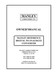
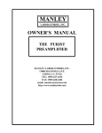
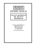
OWNER'S MANUAL
LANGEVIN
ELECTRO-OPTICAL
LIMITER
MANLEY
LABORATORIES, INC.
MANLEY LABORATORIES, INC.
13880 MAGNOLIA AVE.
CHINO, CA. 91710
TEL: (909) 627-4256
FAX: (909) 628-2482
email: emanley @ netcom.com
http://www.manleylabs.com
CONTENTS
SECTION
PAGE
INTRODUCTION
3
MAINS CONNECTIONS
4
OPERATION NOTES
5&6
FRONT PANEL
7
REAR PANEL
8
TROUBLE SHOOTING
9 & 10
INTERNAL ADJUSTMENTS
11
SPECIFICATIONS
12
WARRANTY
13
WARRANTY REGISTRATION
14
INTRODUCTION
THANK YOU!...
for choosing the Langevin Stereo Electro-Optical Limiter. This Limiter follows in the tradition of
the vintage LA-3A Leveling Amplifier using a passive electro-optical device to control gain. The
advantage of a passive device is that it eliminates the need to push the music through many transistors
and / or ICs as would be the case in a VCA based Limiter. Also like the LA-3A, the Langevin utilizes
a minimalist discrete transistor line amplifier for make-up gain. This is one of our favorite clean and
powerful line drivers. Other owners of this unit love the way they can drastically (10 dB) limit
without introducing unmusical harshness. An important feature is that it is quick and easy to use. Also
rare is that it limits in a way that engineers expect when they patch in a limiter. For critical vocal tracks
- this is the one to demand.
Unlike the LA-3A, we use LEDs to illuminate the photo-resistor rather than electroluminescent elements which are often slow and unreliable. We also use a solid state side-chain to
drive the LEDs. The Limiter also features a BYPASS switch that retains the tube section at unity gain
as well as an innovative BALANCE control to "fine tune" the stereo image in LINK mode. Around
Manley Labs we call the unit "The Langevin ELOP".
Please take a few moments to read through this manual carefully as it contains information essential
to proper operation of this unit. Thank you again, and please enjoy
GENERAL NOTES
LOCATION & VENTILATION
The Langevin Electro-Optical Leveling Amplifier must be installed in a stable location with ample
ventilation. It is recommended, if this unit is rack mounted, that you allow enough clearance on the
top and bottom of the unit such that a constant flow of air can move through the ventilation holes.
WATER & MOISTURE
As with any electrical equipment, this equipment should not be used near water or moisture.
SERVICING
The user should not attempt to service this unit beyond that described in the owner's manual.
Refer all servicing to Manley Laboratories.
WARNING!
!
TO PREVENT THE RISK OF ELECTRIC SHOCK
DO NOT OPEN THE CABINET
REFER SERVICING TO
QUALIFIED PERSONEL
3
MAINS CONNECTIONS
Your Limiter has been factory set to the correct mains voltage for your country. The voltage
setting is marked on the serial badge, located on the rear panel. Check that this complies with
your local supply.
Export units for certain markets have a moulded mains plug fitted to comply with local requirements. If your unit does not have a plug fitted the coloured wires should be connected to
the appropriate plug terminals in accordance with the following code.
GREEN/YELLOW
BLUE
BROWN
EARTH
NEUTRAL
LIVE
terminal
terminal
terminal
As the colours of the wires in the mains lead may not correspond with the coloured marking
identifying the terminals in your plug proceed as follows;
The wire which is coloured GREEN/YELLOW must be connected to the terminal in the plug
which is marked by the letter E or by the safety earth symbol or coloured GREEN or GREEN
and YELLOW.
The wire which is coloured BLUE must be connected to the terminal in the plug which is
marked by the letter N or coloured BLACK.
The wire which is coloured BROWN must be connected to the terminal in the plug which is
marked by the letter L or coloured RED.
DO NOT CONNECT/SWITCH ON THE MAINS SUPPLY UNTIL ALL OTHER
CONNECTIONS HAVE BEEN MADE.
Note: This unit has been factory wired for your country. If you plan to take the unit to
countries with a different mains voltage you will need to send the Limiter to Manley Labs
for the correct power transformer - or use AC voltage converters.
4
OPERATION NOTES
The Langevin Electo-Optical Limiter follows certain traits and traditions established by the
UREI LA-3A and similar levelling amplifiers. These traits can be divided into two aspects - electronic
and operation. The electronic concept is simple and rather clean. Use the audio to light up LEDs which
shine onto photo-resistors. These photo-resistors in combination with a fixed resistor simply act as a
voltage divider to attenuate the signal. The line amplifier only functions to provide extra gain to make
up for attenuation losses and then act as a fine cable driver. Simple, elegant and minimal. Operation
aspects are also simple, elegant and minimal. There are usually only a "threshold" and "gain" control.
Most have no user adjustment of "attack", "release", "ratio" or functions for de-essing or external
sidechains. The user is "stuck" with fixed time constants and a feature list that seems anemic compared
to dynamic processors costing far less.
So why are "LA" style opto based limiters so popular ? Several reasons. To paraphrase Letterman
"The number one reason why "LA" style limiters are favorites is because.... they work right on vocals".
This "rightness" has a few aspects. The first is that "LA" style limiters don't leave much trace of limiting
as they work. This is partly due to tubes, partly to the simplicity of the opto circuit and partly because
the user can't alter the attack and release. Almost every VCA based design seems to leave electronic
personality on that critical vocal track. This is usually undesirable. Our Opto circuits has no active
limiting in the signal path. Tube circuits have the potential to be musically more transparent than
transistors because tubes are generally more linear devices. However, there are many poor examples of
tube circuits in use, and many ways to butcher the quality. We chose to use our Langevin line amplifier
circuit which we also use in the Langevin Enhanced Pultec Equalizers (rather than copy UREI designs)
because frankly our circuit sounds better and cleaner.
Back to this matter with fixed time constants. We get requests to modify our "ELOP" for more
controls but we get even more people raving about how great and useful the "ELOP" is now. The attack,
release, knee and ratio (curve) are a function of the Vactrol Cell we chose to use. The choice was based
on the attack and release characteristics. Changing the time values in this circuit involves different
choices of Vactrols. Not practical. Not in a "LA" style limiter. There is a major advantage to fewer
controls. You simply adjust the Threshold for the desired limiting amount and adjust the Gain for the
desired level to tape - then record. The limiter does what its supposed to do - nothing more - nothing less.
Kinda like automatically right, strangely quick and easy, and pretty much non-distracting. We use the
phrase "Set it and forget it". This is a very important feature that would be lost with a variety of controls.
A good engineer wants to be ready to record "now" and does not want to be fussing with controls while
a lead vocal is going to tape. Unfortunately most compressors drag the engineer's attention away (and
often the singer's and producer's attention away as well).
The time and slope characteristics of Opto elements are not easy to describe and probably even
more difficult to simulate. The attack is fast, not super fast "brick wall", but fast enough to "catch"
consonants. It is also a function of level. At lower reduction levels and lower peaks the Vactrol is slower.
It becomes faster with sharp peaks and heavier levels of reduction. Release is similar but 10 to 20 times
slower. Quick peaks are handled with quick release and as gain reduction nears zero the Vactrol gets
slower like gentle braking to a stop. It is possible to"trick out" an opto circuit for conventional operation
but generally the results have been not well liked.
5
The slope or ratio is also difficult to simulate. The initial ratio is low and becomes higher
with more gain reduction until the leds light up fully and further reduction is not easy. This upper
limit of reduction is in the area of 20 dB or at the bottom of the GR meter where the ratio becomes
low again but this would be a severe setting that few engineers could use. Distortion becomes
audible at very deep limiting. In a tech shop, it is easy to drive the limiter to 20 dB of reduction and
beyond where the GR meter shows a flaw in that it "folds back". We put a higher priority on having
the meter show what the Opto was doing accurately with "normal settings" than extreme test bench
observations. Test benches don't make hit records.
So the Opto Limiters seem to be great for vocals, what else are they used for and what about
sounds where the time constants are less than optimum ? Historically "LA" style limiters are often
used for bass and guitar tracks. They can be ideal for brass, saxes, synths and similar sounds with
superb results. There are other compressors that work well for these instruments but few that are as
transparent. Usually, when you hear of an engineer using a non-Opto compressor for these
instruments it is usually framed with "for the crunch" or because they add some desired color. There
is only a very small number of "clean" general purpose variable time compressors which seem to
give Opto units competition - our Variable MU is at the top of that list. Where the "LA" style
limiters are not always appropriate is for percussion and for mixes where the percussion is just right.
The Opto typically reacts fast to peaks - fast enough to remove drums from a mix but not quite fast
enough to be called "brick wall". Individual drums tend to have a little of the initial transient let
through but the desirable tone of the drum is diminished. If used gently, this can be applied to
brighten up the attack of the drum, but it is difficult to apply in practice because drums can be very
dynamic. One great use is on the room mics. The initial drum sound is pulled down, then the natural
reverb is increased. Shades of early Led Zep. While we mentioned that "LA" style limiters are not
what we suggest for mixes, there are times when the drums are too loud or when the engineer can
mix "into" the limiter. Both techniques are possible but not necessarily easy. One trick is very little
movement on the GR meter. Some of our clients use the Opto on mixes as an effect. This application
is valid as long as the effect given and the effect desired are the same. There is not many options for
adjustment and fine tuning. The good news is that at least the Manley is clean enough to pass a good
mix. In a live sound setting the Opto will perform as a fine speaker protection device. Once again the
Threshold is set for minimal limiting with music and is just adjusted to encourage the pyrotechnician
to try harder tomorow to damage your system.
The Balance Control deserves some description. Often, with stereo tracks, once you apply
limiting the apparent left/right balance shifts a little - even in link. While the Link switch makes both
channels equal in gain reduction, the change may still happen. The clues we use to establish position
include volume, transients and ambience as well as delay and tone differences. Limiting involves
changes with the first three. We included a simple adjustment to assist slight trimming to restore the
desired image center. Turning the Balance control Left increases the Left input up 1 dB and
decreases the Right input by 4 dB and turning the Balance to the Right raises the right and lowers the
left. Use both Thresholds while using Link mode to create the desired reduction. It may be easiest to
"get in the ballpark" in normal mode. A slight change in Threshold and Output is expected when you
switch to Link.
6
FRONT PANEL
F
G
A
B
C
D
E
E
D
C
B
A H
NOTE: Right channel is a mirror image of the Left
We do this to preserve exact similarity of the audio electronics (path length, PCB layout, etc)
A
IN / BYPASS. Audio still flows through the tubes in BYPASS but at Unity Gain. Switching
to IN provides the Limiting controls and functions. Use this switch to verify that the limiting
is not messing up the original sound but enhancing it or at least levelling the volume.
B
REDUCTION. Adjusts the amound of limitng in the that channel. This could also be called
Threshold. Turning this clockwise introduces limiting.
C
GAIN Adjusts the gain of that audio channel. Unity gain is about the seventh marking or 1
o'clock. Limiting usually requires some additional "make-up" Gain to compare IN / BYPASS.
The Gain control can also be used as the level to tape.
D
METER SELECT Switch to REDUCTION to see the amount of limiting in dB. The wider
and quicker the reduction meter swings the more likely the limiting will be audible.
Switch to OUTPUT to show the output level as a conventional VU meter.
E
METER Shows the amound of gain reduction in dB from the 0 dB mark. Functions as a
high quality VU meter when the switch is set to METER OUTPUT. Note that VU meters and
PEAK meters rarely agree and that digital recorders use peak meters - Rely on those for clean
recording. VU meters are standard with analog machines and big consoles because they
correspond well with perceived loudness.
F
STEREO LINK / NORMAL Switching the toggle UP provides the STEREO LINK. It is
used on stereo tracks so that when either channel is called to limit, both channels reduce the
same amount at the same time. This prevents image shifts and an instrument should stay
where you panned them. Limiting individual sounds is usually done with the switch down
where each side is independent of the other.
G
STEREO ADJUST Active only in LINK mode. It offers a quick and easy control to adjust
the LEFT / RIGHT BALANCE by few dB. One side increases by 1 dB while the other side
drops by 4 dB. It operates on the input signal before everything.
H
POWER SWITCH Switch up to turn the unit ON.
7
REAR PANEL
A
B
D
C
F
E
K J
I
G
A
1/4" INPUT (BALANCED) (RIGHT)
B
XLR INPUT (BALANCED) (RIGHT)
C
1/4" OUTPUT (UNBALANCED) (RIGHT)
D
XLR OUTPUT (BALANCED) (RIGHT)
E
IEC MAINS CONNECTOR Standard IEC mains connector for 50 /60 Hz AC.
F
MAINS FUSE Replace with only a 1 Amp slo-Blo fuse.
G
XLR INPUT (BALANCED ) (LEFT)
PIN 1: GROUND
PIN 2: HOT (+)
PIN 3: GROUND
H
1/4"INPUT (BALANCED ) (LEFT)
TIP: HOT
SLEEVE: GROUND
I
XLR OUTPUT (BALANCED) (RIGHT) PIN 1: GROUND
PIN 2: HOT (+)
PIN 3: GROUND
J
1/4" INPUT (UNBALANCED) (RIGHT)
K
GROUND TERMINALS
H
TIP: HOT
SLEEVE: GROUND
Any of the "balanced inputs can be used with unbalanced sources
PIN 1: GROUND
PIN 2: HOT (+)
PIN 3: GROUND
TIP: HOT
SLEEVE: GROUND
Use only 1/4" MONO (tip - sleeve) plugs with these jacks otherwise levels will be low.
PIN 1: GROUND
PIN 2: HOT (+)
PIN 3: GROUND
TIP: HOT
SLEEVE: GROUND
Use only 1/4" MONO (tip - sleeve) plugs with these jacks otherwise levels will be low
BLACK = CIRCUIT GROUND
or "Audio Ground"
GREEN = CHASSIS GROUND
or "Electrical Ground" ie mains pin 3
Generally these two ground terminals are connected together with the included "ground strap"
(a small flat piece of metal) but they can be individually used for different grounding systems.
Another use for these is in troubleshhoting HUM problems. Experiment with attaching a wire from
the console to only the BLACK terminal or connecting the GREEN to a rack, (etc).
8
TROUBLE-SHOOTING
There are a number of possible symptoms of something not quite right, some may be interfacing, others we will touch
on as well. The preceding page shows that all the inputs and outputs of the Electro-Optical Limiter are unbalanced. No need
to panic. We have sold hundreds of these units and less than 1% ever had a problem with hum or interfacing to balanced
consoles or other gear. However if you suspect a problem the following paragraphs should help.
NO POWER, NO INDICATORS, NADA - Probably something to do with AC power. Is it plugged in? Check the fuse on
the back panel. A blown fuse often looks blackened inside or the little wire inside looks broken. A very blackened fuse is a
big hint that a short occured. Try replacing the fuse with a good one of the same value and size. If it blows too then prepare
to send the unit back to the dealer or factory for repair. The fuse is a protection device and it should blow if there is a problem.
If the unit works with a new fuse, fine. Check the MAINS VOLTAGE SELECTOR if one is fitted. Some of our models are
able to have them and some don't. It should be set correctly for your mains voltage.
LIGHTS BUT NO SOUND - First try plugging the in and out cables into some other piece of gear to verify that your wires
are OK. Assuming that it was OK into the other unit it probably is still a wiring thing. The AES standard calls PIN 2 HOT
on XLRs but there is still lots of gear out there with PIN 3 HOT. When two units are connected and both are unbalanced but
don't seem to agree which pin is hot - the signal is shorted out. If it is not lost entirely, it will be almost gone and extremely
distorted. THE CURE - a phase reversing adapter that swaps pin 2 and pin 3 on one XLR - or get out a soldering iron and
swap wires yourself. All Manley gear after 1995 is pin 2 hot. Some Manley gear has balanced and floating outputs and some
has unbalanced transformerless outputs. This unit has two discrete line drivers - one driven from the other. If the XLR pin
2 is shorted to ground or pin 3 there will be no signal from the XLR. If pin 3 is shorted to ground - a typical way to drive
unbalanced inputs - then the output on pin 2 will be 6 dB low. The best way to drive unbalanced inputs is with the unbalanced
outputs.
LEVELS SEEM TO BE WRONG, NO BOTTOM - Several possible scenarios.
The above paragraph describes the output line drivers. If you are using the balanced XLR outputs and feeding an unbalanced
input (it happens) you will only be getting 1/2 the signal which means that you lost 6 dB. There is a "trick" if you just want
to use the XLRs but from time to time feed unbalanced inputs. Insert a 1/4" mono (tip - sleeve) plug (unwired) into the
unbalanced output. This makes the levels right. You could leave this plug in permanently but we don't recommend it because
you can have 6 dB more headroom into balanced inputs if it is removed. More headroom is one of the biggest factors of great
sounding gear.
Manley uses the professional standard of +4 dBm = Zero VU = 1.23 volts AC RMS. A lot of semi-pro gear uses the hi-fi
reference of -10 dBm = Zero VU. This is a 14 dB difference that will certainly look goofy and may tend to distort. Often there
are switches on the semi-pro gear to choose the pro reference level. We do not provide that kind of switch because of inevitable
compromises in the signal path. If the loss looks close to 6 dB and it sounds thin then one half of the signal is lost. The cause
is probably wiring again. One of the two signal carrying wires (the third is ground / shield on pin 1) is not happening. Check
the cables carefully because occasionally a cable gets modified to work with a certain unit and it seems to work but its wrong
in other situations. If only one side of the Limiter exhibits this problem, it may be a problem in the Limiter. See the next item.
If you have almost no signal and what you can hear is distorted then you probably have pin 2 shorted to ground or to pin 3.
This might happen if the cable is mis-wired and/or you are feeding an unbalanced input.
USING THE 1/4" JACKS BUT THE LEVEL IS LOW - The 1/4" output jacks on this unit are unbalanced and require
a mono plug (tip - sleeve plug) and not a stereo plug (tip - ring - sleeve plug. The Limiter uses the ring to set the output level
for this output. When the ring is shorted to the sleeve the output becomes 6 dB louder. This is needed because the XLR has
differential outputs which together give that extra 6 dB. Using the ring compensates for this difference and both outputs will
be the same level (+4 dBv). Other manufactures often use a common circuit that does this in a different automatic way. The
generic name is "transformer like" but unlike transformers, these outputs can be unstable (oscillates) into some cables and
often have low headroom into unbalanced inputs. Our method works better as long as one uses a mono phone plug.
We have included an appendix: WIRING YOUR OWN CABLES that may help.
For reference both the XLR and 1/4" inputs are balanced electronically and not with a transformer. The inputs will work fine
and should reject hum from either balanced or unbalanced outputs.
9
HUM - Let's assume it knows the words. Once again - several possibilities - several cures. Most likely it is a ground loop.
The two most common procedures are: try a 3 pin to 2 pin AC adapter (about a dollar at the hardware store) which is better
than messing up the power cable by bending the ground pin until it breaks off. Method two - cutting the shield on one side
of the cable. This is usually done at every female XLR to "break" all loops. You may get a loop simply from the rack. All
the other gear in the rack is "dumping" ground noise onto the rack rails. Try removing the Limiter from the rack so that it is
not touching any metal. You may have cured a non-loop hum. Some gear radiates a magnetic field and some gear (especially
if it has transformers) might receive that hum. A little distance was all it took. This unit has GROUND terminals on the back
panel. Normally these terminals are simply connected together with a "ground strap" (a small flat piece of metal that can
become lost). First check that the strap is connecting the two ground terminals. If missing try a short piece of wire to connect
these terminals. Not that - try separating them, try connecting a wire from the rack to the each terminal, try connecting a wire
from the console to the terminals (one at a time). These terminals are meant to help with a variety of different studio "grounding
schemes". Experiment - you will come up with the best way for your situation.
A cool method of reducing all sorts of hum and noise is to use the new 60-0-60 balanced AC power transformers available
from Equi=Tech and Furman. It costs more but works best. Hum might be because of the unbalanced input but this hints at
ground loops and questionable wiring.
THE METERS ARE OUT OF CALIBRATION - If the problem only seems to be when the unit is just turned on it's normal.
It should warm up. It might be a half dB out for 15 minutes - relax. If they drift a tenth of a dB over the course of a day it is
because of bad AC power fluxuations - chances are other gear is doing worse, you just haven't found out yet. Your unit will
have been factory calibrated and tested twice before you received it. Sometimes parts drift a bit in value over the years, or
you have repaced tubes and want the unit calibrated at the same time, or you just want it as perfect as it can be. These are good
reasons to turn the page and go through the calibration procedure or sent it to a technician or the factory for a tweak. If you
send the unit to a tech, you should include this manual because they will need it. If you do it yourself, you will need an
Oscillator and a few screwdrivers and it would be nice to have a VOM meter and Scope but not necessary.
Once in a while we get a call from a client with a "digital studio" with confusion about levels. They usually start out by using
the digital oscillator from their workstation and finding pegged VU meters the first place they look and they know it can't be
the workstation. Even a -6 level from their system pegs the meters. Some of you know already what 's going on. That -6 level
is referenced to "digital full scale" and the computer might have 18 or 18.5 or 20 dB of headroom built in. That -6 level on
the oscillator is actually a real world analog +12 or +14 and those VU meters don't really go much further than +3. There are
a few standards and plenty of exceptions. One standard is that pro music (non-broadcast) VU meters are calibrated for 0VU
= +4 dBm =1.228 volts into 600 ohms. Another standard is that CDs have a zero analog reference that is -14 dB from digital
full scale or maximum. This allows sufficient peak headroom for mixed material but would be a bad standard for individual
tracks because they would likely distort frequently. This is why digital workstations use higher references like 18 and 20 to allow for peaks on individual sounds. It may be too much in some cases and too little in others. Add two other sources of
confusion. Peak meters and VU meters will almost never agree - they are not supposed to. A peak meter is intended to show
the maximum level that can be recorded to a given medium. VU meters were designed to show how loud we will likely hear
a sound and help set record levels to analog tape. By help, I mean that they can be only used as a guide combined with
experience. They are kinda slow. Bright percussion may want to be recorded at - 10 on a VU for analog tape to be clean but
a digital recording using a good peak meter should make the meter read as high as possible without an "over". Here is the
second confusion: There aren't many good peak meters. Almost all DATs have poor peak meters that do not agree with each
other. One cannot trust them to truly indicate peaks or overs. Outboard digital peak meters (with switchable peak hold) that
indicate overs as 3 (or 4)consecutive samples at either Full Scale Digital (FSD) are the best. They won't agree with VU meters
or Average meters or BBC Peak meters either. Each is a different animal for different uses. The Limiter should help digital
and analog achieve consistent levels but use each meter for it's own strength. The Reduction mode is useful with everything.
We hear the phrase "brick wall limiter" bantered about these days. Theoretically this kind of limiter would be ideal just before
an analog to digital converter or broadcast transmitter. Unfortunately, we don't know of one that sounds OK for most mixes
or general purpose applications. This limiter is better than most for this application but it is not a perfect ultra-fast brick wall.
It is fast enough to significantly reduce transients in a mix (kills drums) and has a steep ratio (better than 10:1) after a few
dB of limiting (soft knee). It will allow for several dB louder mixes and/or no percievable A to D distortion. If used for this
purpose, we suggest that one only uses a few dB of gain reduction or else your mix may change. The alternative is to "mix
into the limiter" so that mix decisions are based on hearing how the limiter is reacting. This can be a little dangerous with
material that has changes in dynamics. It works best with automated mixes and awareness that drums may be a moving target.
10
INTERNAL ADJUSTMENTS
1
5
4
8
2
1)
9
6
7
10
3
+36 Volt DC adjust with meter from ground to resistor marked by arrow. Check this first and adjust if
needed. It is the power supply regulator adjustment. Now for the audio ....
You will have to start out by setting front panel controls to these settings. BYPASS mode, SEP (
LINK OFF ), REDUCTION controls counter clockwise (MIN), GAIN to 1:00 or unity, Balance
at 12:00. The top will need to be open. There are two screws on the top that hold the top perforated
panel to the back. Remove these and the perforated top will slide back. Be careful! THERE ARE
HIGH VOLTAGES INSIDE THE LIMITER. DO NOT HOLD THE METAL PART OF THE
SCREWDRIVER. DO NOT PROBE AROUND WITH THE SCREWDRIVER OR FINGERS. The
unit should be on for about 15 minutes to allow for "warming up".
2 & 3) This adjusts theamplifier gain in all modes. 1 KHz sine at 1.23 volts RMS (+4 dBm, 0 VU) to
both inputs. BYPASS mode. Adjust 2 & 3 for unity gain at outputs.
4 & 5) This adjusts VU meter calibration for OUTPUT. Same input, Meter switches to OUTPUT. Adjust for
0 VU on the Meters.
6 & 7) This adjusts the meter zero for Reduction mode. Meter switches to REDUCTION. Adjust for 0 VU on
the Meters.
8 & 9) This adjusts the meter in Reduction mode to reflect the actual gain reduction accurately. You will
probably need to increase the oscillator 10 dB to get Limiting. Switch from BYPASS to IN. Meter
switches to OUTPUT. Adjust GAIN controls to get 0 VU on the METERS again, then adjust
REDUCTION controls to reduce the signal to -4dB. Switch METERS to REDUCTION. Adjust 8 &
9 to get -4 dB on the METERS.
10)
This adjusts the gain of the right side chain and adjusts the side chain balance in Link. Switch the
LINK ON. There should be 1 to 2 dB change in the Meters. Adjust 10 so that the meter is the
same for both sides. You may have to re-adjust 8 and 9. Check that both in LINK and
SEPARATE that both channels show the same reduction.
This is a final check to verify that all adjustments are OK and the unit is ready for use. Confirm that 0
VU on the meters is +4 dBm with an external VU meter or VOM that reads between 1.22 and 1.23
volts AC and that gain reduction reads the same on OUTPUT and REDUCTION and that LINK or
UN-LINK does not reduce the gain unevenly on the two sides. Remove the power and slide the top in
all the way where it will fit into a groove in the front panel and put those two top screws back in.
Done !
SPECIFICATIONS
Langevin Electro- Optical Limiter
Maximum Input (Bypass through Line Amplifier) +30 dBv
(with Limit "IN" the maximum is entirely variable)
Maximum Output
+30 dBv
Headroom (referenced to +4 dBv)
26 dB
Frequency Response:
10 Hz to 70 kHz +/- 0.5 dB
THD & Noise (1kHz @ +4 dBm)
.015%
Noise Floor (Gain set to minimum)
-80 dB Wideband
Signal to Noise
126 dB typical
Maximum Gain
15 dB
Maximum Limiting
22 dB
Maximum Limiting with +4 dBm sine
15 dB
Attack Time
50 mS
Release Time
1.5 Seconds
Power Consumption
.35 Amps @ 115 VAC
Fuse
1 Amp Slo-Blo
Size (1U)
19" x 1.75" x 10"
Actual Weight
9 Lbs
Shipping Weight
10 Lbs
12
WARRANTY
All Manley Laboratories equipment is covered by a limited warranty against defects in materials
and workmanship for a period of 90 days from date of purchase to the original purchaser only. A
further optional limited 5 year warranty is available to the original purchaser upon proper
registration of ownership within 30 days of date of first purchase.
Proper registration is made by filling out and returning to the factory the warranty card attached to
this general warranty statement, along with a copy of the original sales receipt as proof of the
original date of purchase. Only 1 card is issued with each unit, and the serial number is already
recorded on it.
If the warranty registration card has already been removed then this is not a new unit, and is
therefore not warranted by the factory. If you believe this to be a new unit then please contact the
factory with the details of purchase.
This warranty is provided by the dealer where the unit was purchased, and by Manley Laboratories,
Inc. Under the terms of the warranty defective parts will be repaired or replaced without charge,
excepting the cost of tubes. No warranty is offered on tubes, unless:
1. a Manley Laboratories preamplifier is used with a Manley Laboratories amplifier, and
2. the warranty registration card is filled out.
In such a case a 6 month warranty on tubes is available with the correct recording of the serial
number of the preamplifier on your warranty registration card.
If a Manley Laboratories product fails to meet the above warranty, then the purchaser's sole
remedy shall be to return the product to Manley Laboratories, where the defect will be repaired
without charge for parts and labour. The product will then be returned via prepaid, insured freight,
method and carrier to be determined solely by Manley Laboratories. All returns to the factory must
be in the original packing, (new packing will be supplied for no charge if needed), accompanied by
a written description of the defect, and must be shipped to Manley Laboratories via insured freight
at the customer's own expense. Charges for unauthorized service and transportation costs are not
reimbursable under this warranty, and all warrantees, express or implied, become null and void
where the product has been damaged by misuse, accident, neglect, modification, tampering or
unauthorized alteration by anyone other than Manley Laboratories.
The warrantor assumes no liability for property damage or any other incidental or consequental
damage whatsoever which may result from failure of this product. Any and all warrantees of
merchantability and fitness implied by law are limited to the duration of the expressed warranty.
All warrantees apply only to Manley Laboratories products purchased and used in the USA.
Some states do not allow limitations on how long an implied warranty lasts, so the above
limitations may not apply to you. Some states do not allow the exclusion or limitation of incidental
or consequential damges, so the above exclusion may not apply to you.
This warranty gives you specific legal rights and you may also have other rights which vary from
state to state.
WARRANTY REGISTRATION
We ask that you please fill out this registration form and send the bottom half to:
MANLEY LABORATORIES
REGISTRATION DEPARTMENT
13880 MAGNOLIA AVE.
CHINO CA, 91710
Registration entitles you to product support, full warranty benefits, and notice of product
enhancements and upgrades. You MUST complete and return the following to validate your
warranty and registration. Thank you again for choosing to use Manley Laboratories.
MODEL ____________________
SERIAL No. ______________________
PURCHASE DATE ______________ SUPPLIER ______________________
-----------------------------------------------------------------------------------------------------PLEASE DETACH THIS PORTION AND SEND TO MANLEY LABORATORIES
MODEL LANGEVIN ELECTRO-OPTICAL LIMITER
SERIAL No._____________________________
PURCHASE DATE ______________ SUPPLIER _______________________
NAME OF OWNER _______________________________________________
ADDRESS ______________________________________________________
CITY, STATE, ZIP ________________________________________________
TELEPHONE NUMBER ___________________________________________
Serial #'s of Associated Manley Laboratories Equipment ___________________
________________________________________________________________