1
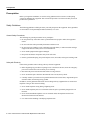
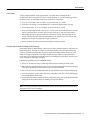
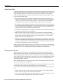
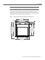
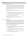
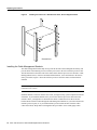
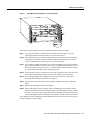
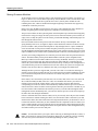
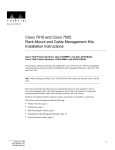
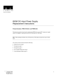
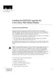
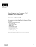
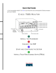
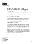
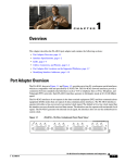
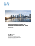
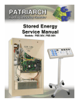
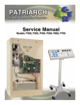
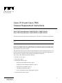
Doc. No. 78-1230-02
Cisco 7010 and Cisco 7505
Chassis Replacement Instructions
Cisco 7010 Product Numbers: CHAS-7010-DC=, CHAS-7010-AC=
Cisco 7505 Product Numbers: CHAS-7505-DC=, CHAS-7505-AC=
This document provides instructions for replacing Cisco 7010 and Cisco 7505 chassis as spare parts.
Note When referring to both the Cisco 7010 and Cisco 7505 chassis, the term the chassis will be
used.
Chassis are available as spare parts, and include all of the components required for operation except
the processor modules. After you replace the chassis, you must move the processor modules from
your old chassis into your new chassis.
The replacement chassis do not include the cable management or rack-mounting hardware kits. You
can move the rack-mounting hardware and cable management brackets from the existing chassis, or
order either kit as a spare part, which will ship with installation instructions.
The sections in this document include the following:
•
•
•
Product Overview, page 2
Prerequisites, page 4
Replacing the Chassis, page 8
— Replacing a Rack-Mounted Chassis, page 9
— Installing the Cable Management Brackets, page 12
— Moving Processor Modules, page 14
— Checking the Installation, page 18
— show Command Descriptions and Examples, page 20
•
Copyright © 1995
Cisco Systems, Inc.
All rights reserved.
Cisco Information Online, page 22
1
Product Overview
Product Overview
The Cisco 7010 is the five-slot model in the Cisco 7000 series. The Cisco 7010 provides three
interface processor slots. Figure 1 shows the interface processor end of the Cisco 7010. The Route
Processor (RP) and Switch Processor (SP) (or Silicon Switch Processor [SSP]), which are required
system components in all Cisco 7000 Series routers, occupy the two top slots. The remaining three
slots support any combination of interface types: Ethernet, Token Ring, FDDI, and so forth.
Figure 1
Cisco 7010—Interface Processor End
RP slot
SP or SSP slot
Interface processor slot 2
Interface processor slot 1
Interface processor slot 0
H2359
Power switch
Chassis ground
screw
Power receptacle
DC OK LED
AC-input power supply
The Cisco 7505 is a five-slot model that provides four interface processor slots. Figure 2 shows the
interface processor end of the Cisco 7505. The Route Switch Processor (RSP1), which is a required
system component in the Cisco 7505 router, occupies the top slot. The remaining four slots support
any combination of interface types: Ethernet, Token Ring, FDDI, and so forth.
Cisco 7505—Interface Processor End
T
E
OL
NS
CO
AU
X.
HA
SE
U
RE
CP
T
EC
Interface processor slot 3
EN
AB
EN
LE
AB
LE
EJ
SL SLO
OT T
0 1
RM
AL
NO
RSP slot
ROUTE SWITCH PROCESSOR
LT
Figure 2
Interface processor slot 2
Interface processor slot 1
Interface processor slot 0
H2761
ower switch
Chassis
grounding
receptacles
Power receptacle
DC OK LED
AC-input power supply
The interface processor end of the chassis also contains the AC power receptacle (a DC-input power
supply is also available, but not shown), the system power on/off switch, and the DC OK power
status LED, all of which are part of the power supply but accessible through cutouts in the chassis
frame. (See Figure 1 or Figure 2.) To the left of the power switch and receptacle cutout is the chassis
ground screw that provides a chassis ground connection for ESD equipment or a grounding wire.
2 Cisco 7010 and Cisco 7505 Chassis Replacement Instructions
Product Overview
The removable chassis cover panel at the noninterface processor end of the router provides access
to the internal components. (See Figure 3.)
Chassis Cover Panel
H2920
Figure 3
Captive screws
Two captive slotted screws secure the chassis cover panel to the noninterface processor end of the
chassis. The cover shields against electromagnetic interference (EMI) and helps direct the flow of
cooling air through the chassis. Therefore, never operate the router with the cover removed.
For detailed descriptions of the system components, refer to the Cisco 7010 Hardware Installation
and Maintenance or Cisco 7505 Hardware Installation and Maintenance publications.
Cisco 7010 and Cisco 7505 Chassis Replacement Instructions
3
Prerequisites
Prerequisites
Before you begin this installation, review the safety guidelines in this section to avoid injuring
yourself or damaging the equipment. This section also provides a list of the tools that you need to
perform this replacement.
Safety Guidelines
The following guidelines will help to ensure your safety and protect the equipment. These guidelines
are not inclusive of all potentially hazardous situations, so be alert.
General Safety Precautions
The following are general precautions for any workplace:
•
Do not perform any action that creates a potential hazard to people or makes the equipment
unsafe.
•
•
Do not work alone when potentially hazardous conditions exist.
•
•
•
Never install equipment that appears damaged.
Do not wear loose clothing, jewelry (including rings and chains), or other items that could get
caught in the chassis. Fasten your tie or scarf and sleeves.
Keep tools and chassis components away from walk areas.
Practice good housekeeping; keep tools and parts clean, accessible, and in good working order.
Safety with Electricity
Follow these guidelines when working with any electrical equipment:
•
Before beginning any procedures requiring access to the chassis interior, locate the emergency
power-off switch for the room in which you are working.
•
•
•
Disconnect all power and external cables before moving a chassis.
Never assume that power has been disconnected from a circuit; always check.
Carefully examine your work area for possible hazards such as moist floors, ungrounded power
extension cables, and missing safety grounds.
In addition, use the guidelines that follow when working with any equipment that is connected to
telephone wiring or other network cabling:
•
•
Never install telephone wiring during a lightning storm.
•
Never touch uninsulated telephone wires or terminals unless the telephone line has been
disconnected at the network interface.
•
Use caution when installing or modifying telephone lines.
Never install telephone jacks in wet locations unless the jack is specifically designed for wet
locations.
4 Cisco 7010 and Cisco 7505 Chassis Replacement Instructions
Prerequisites
Lifting Safely
A fully configured chassis weighs approximately 70 pounds. Before installing the new
(replacement) chassis, ensure that your site is properly prepared, so you can avoid having to move
the chassis later to accommodate power sources and network connections.
•
•
•
•
Never try to lift an object that is too heavy for you to lift safely by yourself.
•
When lifting the chassis, grasp the underside of the chassis exterior with both hands. Do not
attempt to lift the end of the chassis with the handles on the interface processor carriers; these
handles are not designed to support the weight of the chassis.
•
Always disconnect all external cables before lifting or moving the chassis.
Ensure that your footing is solid and balance the weight of the object between your feet.
Lift the object slowly; never move suddenly or twist your body as you lift.
Keep your back straight and lift with your legs, not your back. If you must bend down to lift the
chassis, bend at the knees, not at the waist, to reduce the strain on your lower back muscles.
Preventing Electrostatic Discharge (ESD) Damage
Electrostatic discharge (ESD) damage, which can occur when electronic boards or components are
handled improperly, can result in complete or intermittent failures. The processor modules each
comprise a printed circuit board that is fixed in a metal carrier. EMI shielding, connectors, and a
handle are integral components of the carrier. Handle processor modules by the metal frame or
carrier only; avoid touching the board (particularly avoid touching any components, connector pins,
or the metal fingers on the edge connector).
Following are guidelines for preventing ESD damage:
•
•
Always use an ESD wrist strap or ankle strap and ensure that it makes good skin contact.
•
•
Place removed processor modules board-side-up on an antistatic mat or in a static shielding bag.
•
Avoid contact between the board and clothing. The ESD strap only protects the board from ESD
voltages on the body; ESD voltages on clothing can still cause damage.
When removing or installing interface processors, connect the equipment end of the ground strap
to the chassis ground screw on the interface processor end of the chassis.
If you are returning a replaced part to the factory, immediately place it in a static shielding bag
to avoid ESD damage to the board.
Note For safety, periodically check the resistance value of the antistatic strap. The measurement
should be between 1 and 10 megohms.
Cisco 7010 and Cisco 7505 Chassis Replacement Instructions
5
Prerequisites
Cable Strain Relief
If possible, position the new replacement chassis close enough to the existing system so that you can
avoid having to disconnect power and interface cables. Be sure to disengage any strain relief devices
before attempting to pull the cables from the port. Following are descriptions of the different
methods of strain relief that are used on the AC-input and DC-input power cables and the various
types of network interface cables:
•
On the AC power input receptacle (on the interface processor end of the AC-input powered
chassis), a cable retention clip (see Figure 1 or Figure 2) snaps up around the plug on the power
cord to prevent it from being inadvertently pulled out of the receptacle. Before attempting to
disconnect the power cable, be sure to push the retention clip down away from the plug.
•
On the DC-input power supply, a nylon cable tie is used to fasten the power cable to a bracket
located just below the input terminal block. Carefully cut this cable tie before you disconnect the
power cable leads from the terminal block, and replace the cable tie after you install the new
chassis and wire the power cable leads to the terminal block.
•
Serial interface cables (all types) use thumbscrews on the cable connectors that secure the cable
to the Fast-Serial Interface Processor (FSIP) port.
•
Ethernet interface cables use either slide-type locks or thumbscrews. Although all Ethernet
Interface Processors (EIPs) ship from the factory with slide-type locks on each port, all EIPs also
include conversion kits for replacing the slide-type locks with jackscrews to accommodate
Ethernet interface cables with thumbscrews.
•
Multimode, Fiber Distributed Data Interface (FDDI) connectors use small plastic arms on two
sides of the connector that act like springs and are constrained by the inside of the connector port.
To remove a multimode cable from a FDDI Interface Processor (FIP) port, pinch the two plastic
arms inward while pulling the connector out of the port.
When removing any cable, pull the cable out at the connector; never pull or tug on the cable itself.
For detailed descriptions of the system components, refer to the Cisco 7010 Hardware Installation
and Maintenance or Cisco 7505 Hardware Installation and Maintenance publications.
Preparing the Work Area
Although some network downtime is unavoidable while you remove the RP and SP (or SSP) or
RSP1 from their respective chassis, and replace them in the new chassis, you can minimize the
downtime by placing the old and new chassis close together. If your existing chassis is mounted in
a rack and there is space in the same rack or another rack close by, we recommend that you install
the new, empty chassis in the rack before moving the components. (A fully configured chassis
weighs approximately 70 pounds.)
Before installing the chassis in a new rack location, ensure that routing the interface cables to the
new positions will not strain or tangle them.
You can further minimize downtime by leaving interface cables attached when you move interface
processors to the new chassis, provided that doing so will not strain the cables.
Leave network interface cables connected to the interface ports only if the following conditions are
true:
•
You are able to place the new chassis close to the existing chassis, and moving the processor
modules to the new chassis will not strain the interface cables.
•
The new chassis is already located in its permanent location, or you will need to move it only a
few feet into the space vacated by the old chassis when it is removed.
6 Cisco 7010 and Cisco 7505 Chassis Replacement Instructions
Prerequisites
Note If these conditions are not true, for instance, if you must remove a rack-mounted chassis
before you can install the new chassis, you must disconnect all power and network interface cables.
Also, ensure that your new chassis allows sufficient clearance for maintenance: to remove and
replace processor modules and interface cables at the interface processor end, and to access the
internal components at the noninterface processor end. Figure 4 shows the chassis footprint and the
clearance required to remove or install each of the major components.
Figure 4
Chassis Footprint and Clearance Requirements for Maintenance
Chassis foot C
14.25" (36.20 cm)
2"
(5.08 cm)
Power supply width
14.60" to ears (37.08 cm)
Chassis foot C
13.32" (33.83 cm)
Power supply depth
12.00" (30.48 cm)
1.25" (3.18 cm)
Interface processor depth
11.25" (28.58 cm)
Fan tray
Interface processor end
Interface processor width
14.55" (36.96 cm)
Chassis width
17.50" (44.45 cm)
H2818
Chassis depth
17.0" (43.18 cm)
Chassis depth with power cord and cable
management bracket
19.0" (48.26 cm)
Noninterface processor end
Cisco 7010 and Cisco 7505 Chassis Replacement Instructions
7
Replacing the Chassis
Tools and Parts Required
This section lists the tools and parts you will need to complete these replacement procedures. Have
the necessary tools on hand so that you can complete the replacement without interruption:
•
To replace the chassis cover, you need a 3/16-inch, flat-blade screwdriver to loosen the captive
screws on the chassis cover panel
•
To install a replacement chassis, you need a number 1 Phillips and a 3/16-inch, flat-blade
screwdriver for the captive installation screws on the processor modules (most of the carriers use
slotted screws, but some use Phillips screws)
•
To install new cable management brackets or to move brackets from the existing chassis, you
need the following tools and parts (panhead screws are included with the brackets):
— Number 1 Phillips screwdriver
— Two cable management brackets
— Six M3 x 8-mm, Phillips panhead screws
•
If you will mount or replace the chassis in an equipment rack, you also need the following tools:
— Number 2 Phillips screwdriver
— 1/4-inch and 3/16-inch, flat-blade screwdrivers
— Two chassis ears
— Four M4 x 10-mm, Phillips flathead screws to secure the ears to the chassis
— Eight 10-32 x 3/8-inch, slotted binderhead screws to secure the chassis ears to the rack
•
Whenever you remove or install processor modules, have the following equipment on hand to
help prevent ESD damage:
— Antistatic mat or antistatic foam pad in case you need to put one of the processor modules
down
— Your own ESD-preventive strap or the disposable ESD strap that is included with all spares
Replacing the Chassis
The RP, SP (or SSP), and RSP1 are required system components in their respective chassis; you must
shut down the system power before removing or installing any one of these three processor modules.
All interface processors support online insertion and removal (OIR); however, after installing an
interface processor on line, you must wait at least 15 seconds for the system to reinitialize the
interfaces before installing the next interface processor. Therefore, it is more efficient to leave the
power off until all components are moved into the new chassis, then start up the system and check
the entire installation.
If you are installing the new chassis in an equipment rack, proceed to the next section. Otherwise,
proceed to the section “Installing the Cable Management Brackets” on page 12.
8 Cisco 7010 and Cisco 7505 Chassis Replacement Instructions
Replacing the Chassis
Replacing a Rack-Mounted Chassis
This section describes how to replace a chassis that is installed in an equipment rack. The order in
which you remove the existing system, install the new chassis, and replace the components will vary
depending upon the space available in the rack and in the work area.
Some rack configurations, such as an enclosed rack or a rack with a power strip that limits access,
prohibit the normal installation sequence of first installing the chassis in the rack and then installing
the cable management brackets before installing the processor modules. In these situations, you can
move all the components into the new chassis before installing it in the rack, but ensure that you
follow the safety guidelines for lifting and working with electrical equipment that are provided in
the section “Safety Guidelines” beginning on page 4.
If there is sufficient space available in the same rack (or an adjacent rack) and you have a rack-mount
kit available, you can install the new (replacement) chassis before you remove the existing system.
You can minimize downtime and avoid having to disconnect network interface cables by leaving the
existing system operating while you install the empty replacement chassis in the rack. Also, an
empty chassis is significantly lighter and easier to handle than one that is fully configured. Just
ensure that both chassis, when installed, will be close enough to avoid straining the interface cables
connected to the interface processors.
If you must remove the existing system to make room for the replacement chassis, or if you need the
existing rack mounting hardware to mount the new chassis, you will have to disconnect all network
interface cables before removing the existing system from the rack. You can leave the system
components in the old chassis until after you install the new, empty chassis in the rack.
Assess your rack and lab configuration and the equipment you have available, then choose the
appropriate replacement procedure from the following:
•
If you have a spare rack-mount kit available and you are able to install the new, empty chassis
before you shut down and remove the existing one, follow the installation instructions provided
with the rack mount kit, Cisco 7010 and Cisco 7505 Rack-Mount and Cable Management Kits
Installation Instructions (Document Number 78-1231-xx).
•
After you install the new chassis in the rack and install the cable management brackets, proceed
to the section “Moving Processor Modules” on page 14 to move the components. (After you
complete the replacement and check the installation, you will be directed to the following
section, “Removing the Existing Chassis from the Rack,” to remove the empty chassis.)
•
If you must remove the existing chassis before you can install the new one, proceed to the
following section, “Removing the Existing Chassis from the Rack.”
Cisco 7010 and Cisco 7505 Chassis Replacement Instructions
9
Replacing the Chassis
Removing the Existing Chassis from the Rack
Before removing the existing chassis from the rack, you must shut down the system power and
disconnect the power cord and all interface cables. To help avoid problems when you install the new
chassis, label all interface cables with their slot/port address and mark the positions of the chassis
ears (with tape, chalk, or a marker) so that you can install the new chassis in the same position.
Two chassis ears support the chassis in the rack. The ears are secured to the chassis sides and to the
rack posts, so that the chassis is cantilevered off the ears. We recommend that two people perform
this procedure: one person to support the chassis while the other person removes the screws that
secure the ears to the rack.
Follow these steps to remove the existing chassis from the rack:
Step 1 Turn off the system power and disconnect the power cord and all interface cables from the
chassis.
Step 2 Have a second person support the chassis while you perform this step. From the front of
the rack, use a 1/4-inch flat-blade screwdriver to loosen and remove each of the eight
10-32 x 3/8-inch, slotted screws (four on each side) that secure the chassis ears to the rack.
Step 3 Pull the chassis out of the rack and place it on the floor or a table.
Step 4 Use a number 2 Phillips screwdriver to loosen and remove the two M4 x 10-mm, Phillips
flathead screws that secure the ears to the chassis sides.
Step 5 Pull the ears off the chassis, and place the ears and all fasteners aside.
This completes the chassis removal procedure. If you have not yet installed the new chassis in the
rack, proceed to the next section.
Installing the New Chassis in the Rack
Mount the chassis in the rack before connecting any interface or power cables. If possible, install the
new, empty chassis in the rack first, then install the system components from the old chassis. The
chassis is supported in the rack by two chassis ears, which attach to the sides of the chassis and to
the mounting strips on the rack. Each chassis ear has two studs that fit into holes in either the
interface processor end or the noninterface processor end of the chassis, whichever will be in the
front of the rack. To mount the chassis, install the ears on the chassis first, then secure the ears to the
rack mounting posts or strips. We recommend that two people perform this procedure: one person
to support the chassis in the rack while the other person secures the ears to the rack. Before lifting
the chassis, ensure that your path to the rack is unobstructed.
Follow these steps to install the new chassis in the rack:
Step 1 Position the chassis so that the end that will be in the front of the rack is closest to you.
Figure 5 shows the correct orientation if the noninterface processor end of the chassis will
be installed at the front of the rack.
Step 2 Attach the right chassis ear to the chassis first. Hold the ear in the orientation shown in
Figure 5, with the studs pointing toward the chassis and the mounting strip facing you.
Step 3 Insert the two studs through the holes on the side of the chassis. The ear should be flush
against the chassis side.
Step 4 Insert two M4 x 10-mm, Phillips flathead screws through the ears and into the chassis sides.
Use a number 2 Phillips screwdriver to tighten the screws.
10 Cisco 7010 and Cisco 7505 Chassis Replacement Instructions
Replacing the Chassis
Step 5 Repeat Steps 2 through 4 for the left ear. The strip of mounting holes on the front of each
ear should be approximately flush with the end of the chassis. (See Figure 5.)
Installing the Ears on the Chassis
H2917
Figure 5
Step 6 Lift the chassis and move it to the rack. Avoid sudden twists or moves to prevent injury.
Step 7 Insert the rear of the chassis into the rack, pushing it back until the ears meet the front
mounting strips or posts on both sides of the equipment rack. Slide the chassis vertically
along the rails to align the mounting holes in the ears with those in the rack.
Step 8 From the front of the rack, insert all eight 10-32 x 3/8-inch, slotted screws (four on each
side) through the chassis ears and into the mounting strip. (See Figure 6.)
Step 9 When all screws are inserted, use a 1/4-inch, flat-blade screwdriver to tighten each one.
This completes the rack installation. Proceed to the next section to install the cable management
brackets.
Cisco 7010 and Cisco 7505 Chassis Replacement Instructions
11
Replacing the Chassis
Installing the Chassis in a Standard Four-Post, 19-Inch Equipment Rack
H2919
Figure 6
Chassis front
Installing the Cable Management Brackets
The cable management brackets help to keep network interface cables untangled and orderly, and
prevent cables from hindering access to interface processors in the lower interface processor slots.
The brackets attach to the inner sides of the chassis at the interface processor end. Six M3 x 8-mm,
Phillips panhead screws, which are included with the brackets, secure the brackets to the chassis
(three per bracket). Figure 7 shows the interface processor end of the chassis with the brackets
installed.
Note For this procedure, the Cisco 7010 and Cisco 7505 chassis are functionally the same, and are
referred to as the chassis.
Install the brackets on the new chassis first, before you begin moving system components from the
old chassis. If you install the brackets after you move the interface processors and connect the
interface cables, you might have to disconnect the cables to install the screws that secure the
brackets. Route interface cables through the cable management brackets as you connect them to the
interface processor ports (or as you install interface processors that still have interface cables
connected to them). Wrap cable ties through the holes provided to secure small-gauge cables.
12 Cisco 7010 and Cisco 7505 Chassis Replacement Instructions
Replacing the Chassis
Cable Management Brackets—Cisco 7010 Shown
H2045
Figure 7
Follow these steps to install the two cable management brackets on the new chassis:
Step 1 If you have new brackets to install on the new chassis, proceed to Step 4. If you are
removing the brackets from the old chassis, proceed to the next step.
Step 2 At the interface processor end of the existing chassis, push the cables out of the cutouts in
the brackets. The brackets are flexible and allow cables to pass through the access slots;
however, bending them at extreme angles can cause them to break.
Step 3 Use a number 1 Phillips screwdriver to remove the six panhead screws (three per bracket)
that secure brackets to the inner side of the chassis. You might need to disconnect some of
the interface cables to access the screws. If so, label the cables with their slot/port location,
or reconnect them immediately after removing the bracket.
Step 4 At the interface processor end of the new chassis, place a bracket on one of the inner sides
of the chassis and align the three holes in the bracket with the holes in the chassis.
Step 5 Insert and finger-tighten three M3 Phillips screws from the inner side of the chassis,
through the bracket and into the chassis. (See Figure 7.)
Step 6 When all three screws are inserted, use the number 1 Phillips screwdriver to tighten the
screws.
Step 7 Repeat Steps 4 through 6 for the second bracket.
Step 8 When connecting the network interface cables or installing processor modules with the
interface cables attached, route the cables through the cable management brackets as shown
in Figure 7. If you are using very thin cables that slip through the bracket openings, insert
cable ties through the holes in the bracket and wrap them around the cables to secure them.
This completes the cable management bracket installation. Proceed to the next section to move the
processor modules to the new chassis.
Cisco 7010 and Cisco 7505 Chassis Replacement Instructions
13
Replacing the Chassis
Moving Processor Modules
At the interface processor end of the chassis, slots contain the processor modules. (See Figure 1 or
Figure 2.) In the Cisco 7010, the RP occupies the top slot (the RP slot or slot 4) and the SP (or SSP)
occupies the second slot from the top (the SP slot or slot 3), directly below the RP slot. The
remaining three slots, which are numbered 0 through 2 beginning at the bottom slot, support any
combination of interface processors.
In the Cisco 7505, the RSP1 occupies the top slot (slot 4). The remaining four slots, numbered 0
through 3 beginning at the bottom, support any combination of interface processors.
The processor modules are all keyed with guides on the backplane to prevent them from being fully
inserted in the wrong slot. Empty interface processor slots contain an interface processor filler (an
empty carrier) to help keep dust out of the chassis, provide EMI shielding, and maintain proper air
flow through the chassis interior.
Processor modules slide into the processor slots and connect directly to the backplane. The
spring-loaded ejector levers (see Figure 8) help to ensure that the bus connector on the back of the
processor module is fully seated in the backplane or fully dislodged from it. Captive installation
screws at both ends of each processor module faceplate prevent the processor from pulling away
from the backplane and support the EMI integrity of the system. Failure to use the ejector levers and
captive installation screws could result in a partial backplane connection, which can hang the system.
To retain your existing configuration, move interface processors to the same slot positions in the new
chassis. The lithium battery backup on the RP and RSP1 retains the system configuration and
MAC-layer addresses in nonvolatile random-access memory (NVRAM). Therefore, if you install
interface processors in the same slot positions in the new chassis that they occupied in the old
chassis, the system and the individual interfaces should come up in their previous configuration. If
you install interface processors in different slots in the new chassis, the system will recognize the
interfaces, but will leave them in a shutdown state until you reconfigure and enable them.
Although interface processors support OIR, you must wait at least 15 seconds after inserting an
interface processor before inserting the next one. To help avoid errors with the installation, leave the
power off until all components are moved into the new chassis and you have verified that all are
installed properly.
In the chassis, move the interface processors first, one at a time, then, in the Cisco 7010, move the
SP (or SSP) and finally the RP; in the Cisco 7505, move the RSP1 last. Before you remove an
interface processor from the existing chassis, remove the interface processor filler from the
corresponding slot in the new chassis. Then immediately install the interface processor in the new
chassis and secure it in the slot before removing the next interface processor filler or module. If you
leave the interface cables attached to the interface processors, route the cables through the cable
management brackets immediately after you secure the interface processor in the slot to help keep
the other slots clear during the installation.
If there is sufficient slack in the interface cables, and if you can easily move the processor modules
between the chassis without straining the cables, leave the interface cables connected. If you must
disconnect the cables, label each cable with its slot and port number before you disconnect it. Do not
reconnect the interface cables until you have installed all of the components in the new chassis (it is
easier to install interface processors when the slots are not impeded by cables that drop from other
slots). Use the optional cable management brackets to keep the interface cables untangled and away
from other interface processor slots and ports.
Caution You must turn off the system power before removing or installing the RP, SP (or SSP), or
RSP1, all of which are required system components. Removing one while the system is operating
will cause the system to shut down or crash and might damage or destroy memory files.
14 Cisco 7010 and Cisco 7505 Chassis Replacement Instructions
Replacing the Chassis
Ejector Levers and Captive Installation Screws
Interface processor
card slot
Ejector
lever
Interface processor card
carrier guide (black)
a
b
Captive
installation
screw
c
H1984
Figure 8
Cisco 7010 and Cisco 7505 Chassis Replacement Instructions
15
Replacing the Chassis
Follow these steps to move the processor modules to the new chassis:
Step 1 Before moving any processor modules, ensure that you have met the following
prerequisites (refer to the section “Prerequisites” on page 4 for details):
•
On both chassis, ensure that the power is turned off and the power cable is disconnected
from the AC power receptacle or the DC terminal block.
•
To prevent ESD damage, wear a grounding strap or other ESD-prevention device and
attach the equipment end to the chassis ground screw on the interface processor end of
the chassis. (See Figure 1 or Figure 2.)
•
If you will leave the interface cables connected to the processor modules, ensure that
there is sufficient slack to avoid straining the cables when moving the processor
between chassis. Otherwise, label each cable with its slot and port number position.
(This will help avoid mixing up cables when you reconnect them.)
•
Optional: Install the cable management brackets on the new chassis before moving the
components. Either move the brackets from the old chassis or install a new set.
Step 2 Note the slot location of the interface processor you will move. Before removing the
interface processor, remove the interface processor filler from the corresponding slot in the
new chassis. When installing interface processors in the new chassis, place them in the
same slot position that they occupied in the old chassis; this will retain your existing
configuration and will help avoid confusion when reconnecting cables and checking the
installation.
Step 3 If necessary, disconnect any interface cables that are connected to the processor module.
Step 4 Use a screwdriver to loosen both of the captive installation screws. (See Figure 8a.)
Step 5 Place your thumbs on the end of each ejector and simultaneously pull them both outward,
away from the carrier handle (in the opposite direction from that show in Figure 8c) to
release the processor module from the backplane.
Caution In the Cisco 7010, you must install the RP in the slot labeled RP (the top slot) and the SP
(or SSP) in the slot labeled SP (the slot directly below the RP slot). In the Cisco 7505, you must
install the RSP1 in the slot labeled slot 4. For both chassis models, you can install interface
processors in any of the interface processor slots (the lowest slots), but we recommend that you
install them in the same slot positions that they occupied in the old chassis. The slots are keyed for
correct installation. Forcing a processor module into the wrong slot can damage the backplane and
board connectors.
Step 6 Grasp the carrier handle with one hand and pull the processor module straight out of the
slot, keeping your other hand under the carrier to guide it. (See Figure 9.) Keep the carrier
at a 90-degree orientation to the backplane. Avoid touching the board or any connector pins.
Step 7 Place the processor module in the same slot position in the new chassis and align the
notches along the edge of the carrier with the grooves in the slot. (See Figure 8a.)
Step 8 While keeping the carrier at a 90-degree orientation to the backplane, carefully slide the
carrier into the slot until the back of the faceplate makes contact with the ejector levers, then
stop. (See Figure 8b.)
Do not use unnecessary force when installing processor modules. Always guide the carrier
into the slot only until the carrier faceplate makes contact with the ejector levers, then use
the ejector levers to complete the insertion.
16 Cisco 7010 and Cisco 7505 Chassis Replacement Instructions
Replacing the Chassis
Step 9 Using the thumb and forefinger of each hand to pinch each ejector, simultaneously push
both ejectors inward (toward the carrier handle) until they snap into place and are at a full
90-degree orientation to the faceplate. (See Figure 8c.) The carrier ears (the ends of the
faceplate) should be flush against the chassis.
Step 10 Use a screwdriver to tighten the two captive screws to prevent the processor module from
becoming partially dislodged from the backplane and to ensure proper EMI shielding.
Step 11 Repeat Steps 2 through 10 for the remaining interface processors.
Step 12 Repeat Steps 3 through 10 for the SP (or SSP) and RP in the Cisco 7010, and the RSP1 in
the Cisco 7505.
Handling a Processor Module
H1985
Figure 9
Captive installation
screws
Note Leave the interface processor filler installed in any unfilled interface processor slots.
This completes the processor module removal and replacement procedure. If you now need to install
the new chassis in an equipment rack, proceed to the section “Installing the New Chassis in the
Rack” on page 10. Otherwise, proceed to the next section to check the installation.
Cisco 7010 and Cisco 7505 Chassis Replacement Instructions
17
Replacing the Chassis
Checking the Installation
To complete the replacement procedure, perform the following steps to verify that the system is
functioning properly. These steps will also help you verify that all the processor modules you moved
are returned to their previous state. For additional first-time startup troubleshooting procedures, refer
to the Cisco 7010 Hardware Installation and Maintenance or Cisco 7505 Hardware Installation and
Maintenance publications.
Because the lithium battery backup on the RP and RSP1 retains the system configuration in
NVRAM, the system and the individual interfaces should come up in their previous configuration,
provided that you installed the interface processors in the same slots they occupied in the old chassis.
If you installed interface processors in different slot positions in the new chassis, the system will
recognize the interfaces but leave them in a down state until you reconfigure and enable them. If you
need assistance, refer to the section “Cisco Information Online” at the end of this document.
Step 1 Ensure that the system power switch is in the off position, then reconnect the power cable
to the AC receptacle or DC terminal block, as required. For the AC-input power supply,
snap the cable retention clip up around the plug to secure the cable. For the DC-input power
supply, reattach a new nylon cable tie to support the weight of the cable.
Step 2 Connect all interface cables to the appropriate interface processor ports. Ensure that all
cables are fully seated in the ports and that all strain relief systems are engaged.
Step 3 Ensure that you have either a console terminal connected to the system console port or a
port available for a Telnet session to the router.
Step 4 Turn on the system power. The DC OK LED should go on and stay on. If if does, proceed
to the next step. If it does not, do the following:
•
First, check the source power. Ensure that the power switch is completely in the on (|)
position and that the power (input) cord is properly connected at both ends.
•
Listen for the fans; you should hear them operating immediately after turn on the power.
If the DC OK LED is off and the fans are not operating, there is most likely a problem
with the AC or DC input power or with one of the internal DC lines. If so, there are no
installation adjustments that you should make; contact a service representative for
further instructions.
Step 5 While the system initializes, the yellow boot error LED on the RP should go on for about
ten seconds, then go off. Verify that the normal LED on the RP or RSP1 goes on and stays
on, which indicates that the system software booted successfully. If it does, proceed to the
next step. If it does not go on, do the following:
•
Check the ejector levers and captive installation screws on the processor modules. If any
appear loose, use the ejector levers to reseat the module, then tighten the captive
installation screws to secure it. Toggle the power off and back on again.
•
If the RP or RSP1 normal LED still remains off, note whether the boot fail LED (on the
RP) or the CPU halt LED (on the RSP1) goes on, and contact a service representative.
18 Cisco 7010 and Cisco 7505 Chassis Replacement Instructions
Replacing the Chassis
Step 6 When the system boot is complete, the RP or RSP1 begins to initialize the interface
processors. During this initialization, the LEDs on each interface processor behave
differently (most flash on and off). The enabled LED on each interface processor goes on
when initialization has been completed.
•
If the enabled LED on the SP (or SSP) and all interface processors go on, the system
has booted successfully and is now functional.
•
If the RP or RSP1 LEDs previously indicated a successful system boot, but none of the
enabled LEDs on the SP (or SSP) or the interface processors go on, suspect that one of
them has shifted out of its backplane connector and hung the bus. Turn off the power,
then use the ejector levers to release the SP (or SSP) and each interface processor and
reseat them in their slots. (Refer to the section “Moving Processor Modules” on page 14
for removal and insertion steps.) Tighten all captive installation screws, then return to
Step 1.
Step 7 If the enabled LED on a single interface processor remains off, suspect that the interface
processor has shifted out of its slot. Use the ejector levers to release the interface processor
and reseat it in the backplane. (Refer to the section “Moving Processor Modules” on
page 14, for removal and insertion steps.) Tighten both captive installation screws, then
return to Step 1.
Step 8 If an enabled LED still fails to go on after performing these steps, suspect that the specific
SP (or SSP) or interface processor has failed. Contact a service representative.
Step 9 Verify that the console terminal displays a script and system banner similar to the
following:
GS Software (GS7), Version 10.3(3), SOFTWARE
Copyright (c) 1986-1995 by cisco Systems, Inc.
Compiled Wed 10-May-95 14:46 by mpo
System Bootstrap, Version 4.6(1) [fc2], SOFTWARE
Step 10 After the system initializes, use the various show commands to display the status of the
system and individual interfaces, and ensure that they are operating according to their
previous configuration. (For descriptions and examples of these commands, refer to the
following section, “show Command Descriptions and Examples.”)
When the system starts up and operates successfully, the replacement procedure is complete and you
can resume normal operation.
If the system still fails to start up or operate properly, or if you isolate the cause of the problem to a
failed component, contact a service representative for further assistance.
Note After you verify a successful installation, gather the old chassis and any remaining spares and
parts. If the old chassis is still mounted in a rack, follow the steps in the section “Removing the
Existing Chassis from the Rack” on page 10 to remove it. Place spare interface processors or
interface processor fillers in the chassis slots, and move the chassis to the appropriate location for
storage or shipment.
Cisco 7010 and Cisco 7505 Chassis Replacement Instructions
19
Replacing the Chassis
show Command Descriptions and Examples
This section describes the various show commands that you can use to display system status and
configuration. If you installed the interface processors in the same slot locations that they occupied
in the old chassis, the interfaces should retain the same configuration. If you installed the interface
processors in different slot locations, the system will recognize the interfaces, but you will have to
use the configure command to reconfigure and enable them.
The show version command displays the current hardware configuration of the router, including the
system software version that is currently loaded and running. The show controllers cxbus command
lists all CxBus interfaces and includes the currently loaded and running microcode version for each.
You can check the version of the default ROM image either by removing the board and checking the
ROM labels or by configuring the interface or system software to boot from ROM, restarting the
system, and using these same commands to check the running version.
Use the show version command to display the current system software version, and use the show
controllers cxbus command to display the microcode version of the SP and each interface
processor. In the following example of the show version command, the running system software is
Release 10.3(1)).
Router> show version
GS Software (GS7), Version 10.3(3), SOFTWARE
Copyright (c) 1986-1995 by cisco Systems, Inc.
Compiled Wed 10-May-95 14:46 by mpo
System Bootstrap, Version 4.6(1) [fc2], SOFTWARE
Current date and time is Sat 1-22-1994 21:38:35
Boot date and time is Tue 12-28-1993 15:32:28
Router uptime is 3 weeks, 4 days, 6 hours, 7 minutes
System restarted by reload
System image file is “gs7-k.103-1”, booted via tftp from 1.1.1.12
(example text omitted
X.25 software, Version 2.0, NET2 and BFE compliant.
Bridging software.
1 EIP controller (6 Ethernet).
1 TRIP controller (4 Token Ring).
6 Ethernet/IEEE 802.3 interfaces.
4 Token Ring/IEEE 802.5 interfaces.
(remainder of example text omitted)
Following is an example of the show controller cxbus command display. (In this example, ROM
Version 1.0 is assumed because you cannot determine the ROM version with screen displays unless
it is the running version.)
Router# show controllers cxbus
(text omitted from example)
FSIP 1, hardware version 1.0, microcode version 1.0
Interface 8 - Serial1/0, electrical interface is V.35 DTE
(text omitted from example)
Interface 9 - Serial1/1, electrical interface is V.35 DTE
(remainder of displayed text omitted from example)
20 Cisco 7010 and Cisco 7505 Chassis Replacement Instructions
Replacing the Chassis
The command show interfaces serial slot/port displays statistics for the specific serial interface you
specify by its slot/port address. If you use this command without the type and slot/port arguments,
the system will display statistics for all interfaces in the system.
Router> show int hssi 1/0
Hssi 1/0 is up, line protocol is up
Hardware is cxBus HIP
Internet address is 1.1.1.9, subnet mask is 255.255.255.0
(display text omitted)
The command show configuration displays the contents of the system configuration file stored in
NVRAM.
Router# show config
Using 1652 out of 130048 bytes
version 10.3(3)
!
hostname Router
!
enable-password guessagain
!
microcode TRIP flash trip1-0
microcode reload
!
interface hssi1/0
ip address 1.1.1.67
ip route-cache cbus
no keepalive
!
interface serial2/1
ip address 1.1.1.12
(display text omitted)
The command show protocols displays the global (system-wide) and interface-specific status of any
configured Level 3 protocol.
Router> show protocols
Global values:
Internet Protocol routing is enabled
Hssi1/0 is up, line protocol is up
(display text omitted)
Cisco 7010 and Cisco 7505 Chassis Replacement Instructions
21
Cisco Information Online
Cisco Information Online
Cisco Information Online (CIO) is Cisco Systems’ primary, real-time support channel. Maintenance
customers and partners can self-register on CIO to obtain additional content and services.
Available 24 hours a day, 7 days a week, CIO provides a wealth of standard and value-added services
to Cisco’s customers and business partners. CIO services include product information, software
updates, release notes, technical tips, the Bug Navigator, configuration notes, brochures,
descriptions of service offerings, and download access to public and authorized files.
CIO serves a wide variety of users through two interfaces that are updated and enhanced
simultaneously—a character-based version and a multimedia version that resides on the World Wide
Web (WWW). The character-based CIO (called “CIO Classic”) supports Zmodem, Kermit,
Xmodem, FTP, Internet e-mail, and fax download options, and is excellent for quick access to
information over lower bandwidths. The WWW version of CIO provides richly formatted
documents with photographs, figures, graphics, and video, as well as hyperlinks to related
information.
You can access CIO in the following ways:
•
•
•
WWW:
Telnet:
http://www.cisco.com
cio.cisco.com
Modem: From North America, 408 526-8070; from Europe, 33 1 64 46 40 82. Use the
following terminal settings: VT100 emulation; data bits: 8; parity: none; stop bits: 1; and baud
rates up to 14.4 kbps.
For a copy of CIO’s Frequently Asked Questions (FAQ), contact
additional information, contact [email protected].
[email protected].
For
Note If you are a network administrator and need personal technical assistance with a Cisco
product that is under warranty or covered by a maintenance contract, contact Cisco’s Technical
Assistance Center (TAC) at 800 553-2447, 408 526-7209, or [email protected]. To obtain general
information about Cisco Systems, Cisco products, or upgrades, contact 800 553-6387,
408 526-7208, or [email protected].
This document is to be used in conjunction with the Cisco 7010 Hardware Installation and Maintenance or Cisco 7505 Hardware Installation and Maintenance publications.
(1230chas.fm)
Access Without Compromise, Catalyst, CD-PAC, CiscoFusion, Cisco Internetwork Operating System, Cisco IOS, CiscoView, CiscoWorks, HyperSwitch, LAN2LAN, LAN2LAN
Enterprise, LAN2LAN Remote Office, LAN2PC, LightStream, Newport Systems Solutions, PC2LAN/X.25, Point and Click Internetworking, SMARTnet, SynchroniCD, The Packet,
UniverCD, WNIC, Workgroup Director, Workgroup Stack, and XCI are trademarks; Access by Cisco and Bringing the power of internetworking to everyone are service marks; and Cisco,
Cisco Systems, the Cisco logo, EtherSwitch, and Kalpana are registered trademarks of Cisco Systems, Inc. All other trademarks, service marks, registered trademarks, or registered service
marks mentioned in this document are the property of their respective owners.
Copyright © 1995, Cisco Systems, Inc.
All rights reserved. Printed in USA
954R
22 Cisco 7010 and Cisco 7505 Chassis Replacement Instructions