1
Notice
Hewlett-Packard to Agilent Technologies Transition
This documentation supports a product that previously shipped under the HewlettPackard company brand name. The brand name has now been changed to Agilent
Technologies. The two products are functionally identical, only our name has changed. The
document still includes references to Hewlett-Packard products, some of which have been
transitioned to Agilent Technologies.
Printed in USA
March 2000
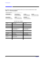
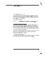
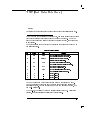
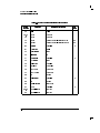
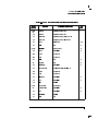
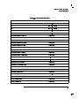
Contacting Agilent
By internet, phone, or fax, get assistance with all your test and measurement needs.
Table 1-1 Contacting Agilent
Online assistance: www.agilent.com/find/assist
United States
(tel) 1 800 452 4844
Latin America
(tel) (305) 269 7500
(fax) (305) 269 7599
Canada
(tel) 1 877 894 4414
(fax) (905) 282-6495
New Zealand
(tel) 0 800 738 378
(fax) (+64) 4 495 8950
Japan
(tel) (+81) 426 56 7832
(fax) (+81) 426 56 7840
Australia
(tel) 1 800 629 485
(fax) (+61) 3 9210 5947
Europe
(tel) (+31) 20 547 2323
(fax) (+31) 20 547 2390
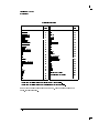
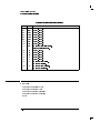
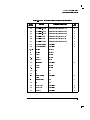
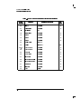
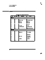
Asia Call Center Numbers
Country
Phone Number
Fax Number
Singapore
1-800-375-8100
(65) 836-0252
Malaysia
1-800-828-848
1-800-801664
Philippines
(632) 8426802
1-800-16510170 (PLDT
Subscriber Only)
(632) 8426809
1-800-16510288 (PLDT
Subscriber Only)
Thailand
(088) 226-008 (outside Bangkok)
(662) 661-3999 (within Bangkok)
(66) 1-661-3714
Hong Kong
800-930-871
(852) 2506 9233
Taiwan
0800-047-866
(886) 2 25456723
People’s Republic
of China
800-810-0189 (preferred)
10800-650-0021
10800-650-0121
India
1-600-11-2929
000-800-650-1101
2
Chapter 1
Programming Guide
HP 83711A/12A and
HP 83711B/12B
Synthesized CW
Generators
HP part number: 83711-90132
Printed in USA
April, 1995
Supersedes 5960-7089
Notice.
The information contained in this document is subject to change without
notice.
Hewlett-Packard makes no warranty of any kind with regard to this material,
including but not limited to, the implied warranties of merchantability and
tness for a particular purpose. Hewlett-Packard shall not be liable for errors
contained herein or for incidental or consequential damages in connection
with the furnishing, performance, or use of this material.
c Copyright Hewlett-Packard Company 1995
All Rights Reserved. Reproduction, adaptation, or translation without prior
written permission is prohibited, except as allowed under the copyright laws.
1400 Fountaingrove Parkway, Santa Rosa, CA 95403-1799, USA
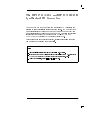
The HP 83711A/12A and HP 83711B/12B
Synthesized CW Generators
The HP 83711A/12A and HP 83711B/12B Synthesized CW Generators are
referred to as \synthesizers" throughout this manual. The HP 83711A/11B
has a carrier frequency range of 1 GHz to 20 GHz and the HP 83712A/12B
has a carrier frequency range of 10 MHz to 20 GHz. Complete specication
information can be found in Chapter 4 in the HP 83711A/12A and
HP 83711B/12B Synthesized CW Generators User's Guide.
This programming guide provides specic, detailed information about the
commands used to program the synthesizer.
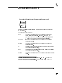
Notes
1. This manual applies to instruments with rmware revision 10.0 or greater.
2. If you have an HP 83711A/12A instrument with rmware revision number < 10.0, refer to the
(5960-7089).
3. To view rmware revision, press 4SPCL5, 415, 4HZ5 (ENTER).
HP 83711A/12A Synthesized CW
Generator Programmer's Reference
iii
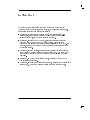
In This Book
This book provides information about the various commands used in
programming the synthesizer, error messages, and regulatory information.
Information is divided into chapters as follows:
Chapter 1, \Getting Started Programming," contains general HP-IB
information, introduces the Standard Commands for Programmable
Instruments (SCPI), and provides example programs.
Chapter 2, \Programming Commands," contains entries on all of the
programming commands used by the synthesizer. This chapter is
subdivided into sections that contain groupings of related commands. For
example, all commands related to automatic level control are grouped in
one tabbed section.
Chapter 3, \Error Messages," contains a list of all of the error messages
that might be generated during use of the instrument. Each entry in the
list contains a sequence that can be followed to recover from the error
condition.
Chapter 4, \HP 8673 Compatibility Guide," contains HP 8673 to SCPI
compatibility information.
Chapter 5, \Legal and Regulatory Information," contains SCPI conformance
information. The product warranty is also contained in this chapter.
iv
Contents
1.
Getting Started Programming
HP-IB General Information . . . . . . . . . .
Interconnecting Cables . . . . . . . . . . .
Instrument Addresses . . . . . . . . . . .
HP-IB Instrument Nomenclature . . . . . .
Listener . . . . . . . . . . . . . . . .
Talker . . . . . . . . . . . . . . . . .
Controller . . . . . . . . . . . . . . .
Programming the Synthesizer . . . . . . . .
HP-IB Command Statements . . . . . . . .
Abort . . . . . . . . . . . . . . . . . .
Related statements used by some computers
Remote . . . . . . . . . . . . . . . . .
Some BASIC examples . . . . . . . . . .
Local Lockout . . . . . . . . . . . . . . .
A BASIC example . . . . . . . . . . . .
Local . . . . . . . . . . . . . . . . . .
Some BASIC examples . . . . . . . . . .
Clear . . . . . . . . . . . . . . . . . .
Some BASIC examples . . . . . . . . . .
Related statements used by some computers
Output . . . . . . . . . . . . . . . . . .
A BASIC example . . . . . . . . . . . .
Related statements used by some computers
Enter . . . . . . . . . . . . . . . . . .
Related statements used by some computers
Getting Started with SCPI . . . . . . . . . .
Denitions of Terms . . . . . . . . . . . . .
Standard Notation . . . . . . . . . . . . .
Command Mnemonics . . . . . . . . . .
Angle Brackets . . . . . . . . . . . . .
How to Use Examples . . . . . . . . . . .
Command Examples . . . . . . . . . . .
Response Examples . . . . . . . . . . .
Essentials for Beginners . . . . . . . . . . .
Program and Response Messages . . . . . .
.
.
.
.
.
.
.
.
.
.
.
.
.
.
.
.
.
.
.
.
.
.
.
.
.
.
.
.
.
.
.
.
.
.
.
.
.
.
.
.
.
.
.
.
.
.
.
.
.
.
.
.
.
.
.
.
.
.
.
.
.
.
.
.
.
.
.
.
.
.
.
.
.
.
.
.
.
.
.
.
.
.
.
.
.
.
.
.
.
.
.
.
.
.
.
.
.
.
.
.
.
.
.
.
.
.
.
.
.
.
.
.
.
.
.
.
.
.
.
.
.
.
.
.
.
.
.
.
.
.
.
.
.
.
.
.
.
.
.
.
1-3
1-3
1-5
1-6
1-6
1-6
1-6
1-6
1-7
1-8
1-8
1-9
1-9
1-10
1-10
1-10
1-10
1-11
1-11
1-11
1-12
1-13
1-13
1-14
1-15
1-16
1-17
1-18
1-18
1-18
1-18
1-19
1-19
1-20
1-21
Contents-1
Forgiving Listening and Precise Talking
Types of Commands
. . . . . .
. . . . . . . . . . . . . . . .
Subsystem Command Trees . . . . . . . . . . .
The Command Tree Structure . . . . . . . .
Paths Through the Command Tree . . . . . .
More About Commands . . . . . . . . . . . .
Query and Event Commands . . . . . . . . .
Implied Commands . . . . . . . . . . . . .
Optional Parameters . . . . . . . . . . . . .
Program Message Examples . . . . . . . . . .
Example 1 . . . . . . . . . . . . . . . . .
Example 2 . . . . . . . . . . . . . . . . .
Example 3 . . . . . . . . . . . . . . . . .
Example 4 . . . . . . . . . . . . . . . . .
Reading Instrument Errors . . . . . . . . . . .
Details of Commands and Responses . . . . . . . .
Program Message Syntax . . . . . . . . . . . .
SCPI Subsystem Command Syntax . . . . . . .
Common Command Syntax . . . . . . . . . . .
Response Message Syntax . . . . . . . . . . .
SCPI Data Types . . . . . . . . . . . . . . .
Parameter Types . . . . . . . . . . . . . . .
Numeric Parameters . . . . . . . . . . . . .
Extended Numeric Parameters . . . . . . . .
Discrete Parameters . . . . . . . . . . . . .
Boolean Parameters . . . . . . . . . . . . .
Response Data Types . . . . . . . . . . . . .
Real Response Data . . . . . . . . . . . . .
Integer Response Data . . . . . . . . . . . .
Discrete Response Data . . . . . . . . . . .
String Response Data . . . . . . . . . . . .
Programming Typical Measurements . . . . . . . .
Using the Example Programs . . . . . . . . . .
HP-IB Check, Example Program 1 . . . . . . . .
Program Comments . . . . . . . . . . . . .
Local Lockout Demonstration, Example Program 2
Program Comments . . . . . . . . . . . . .
Internally Leveled CW Signal, Example Program 3
Program Comments . . . . . . . . . . . . .
Level Correction Routine, Example Program 4 . .
Program Comments . . . . . . . . . . . . .
Contents-2
.
.
.
.
.
.
.
.
.
.
.
.
.
.
.
.
.
.
.
.
.
.
.
.
.
.
.
.
.
.
.
.
.
.
.
.
.
.
.
.
.
.
.
.
.
.
.
.
.
.
.
.
.
.
.
.
.
.
.
.
.
.
.
.
.
.
.
.
.
.
.
.
.
.
.
.
.
.
1-21
1-21
1-23
1-23
1-23
1-26
1-26
1-26
1-26
1-27
1-27
1-27
1-28
1-28
1-29
1-30
1-31
1-32
1-33
1-34
1-35
1-36
1-36
1-37
1-38
1-38
1-39
1-39
1-39
1-40
1-40
1-41
1-41
1-42
1-42
1-43
1-44
1-45
1-45
1-46
1-47
Saving and Recalling States, Example Program 5 . . .
Program Comments . . . . . . . . . . . . . . . . .
Related Documents . . . . . . . . . . . . . . . . .
2.
Programming Commands
Command Syntax . . . . . . . . . . . . . . . . . .
2a.
Automatic Level Control Commands
2b.
Carrier Commands
2c.
Instrument Information Commands
[SOURce[1]:]POWer:ALC:PMETer . . .
Query Syntax . . . . . . . . . . .
See Also . . . . . . . . . . . . .
[SOURce[1]:]POWer:ALC:PMETer:STEP
Query Syntax . . . . . . . . . . .
See Also . . . . . . . . . . . . .
[SOURce[1]:]POWer:ALC:SOURce . . .
Query Syntax . . . . . . . . . . .
See Also . . . . . . . . . . . . .
.
.
.
.
.
.
.
.
.
1-50
1-51
1-52
2-3
.
.
.
.
.
.
.
.
.
.
.
.
.
.
.
.
.
.
.
.
.
.
.
.
.
.
.
.
.
.
.
.
.
.
.
.
.
.
.
.
.
.
.
.
.
.
.
.
.
.
.
.
.
.
.
.
.
.
.
.
.
.
.
2a-3
2a-4
2a-4
2a-5
2a-6
2a-6
2a-7
2a-7
2a-8
[SOURce[1]:]FREQuency[:CWj:FIXed] . . .
Query Syntax . . . . . . . . . . . . .
See Also . . . . . . . . . . . . . . .
[SOURce[1]:]FREQuency[:CWj:FIXed]:STEP
Query Syntax . . . . . . . . . . . . .
See Also . . . . . . . . . . . . . . .
[SOURce[1]:]FREQuency:MULTiplier . . .
Query Syntax . . . . . . . . . . . . .
See Also . . . . . . . . . . . . . . .
[SOURce[1]:]FREQuency:MULTiplier:STEP
Query Syntax . . . . . . . . . . . . .
See Also . . . . . . . . . . . . . . .
.
.
.
.
.
.
.
.
.
.
.
.
.
.
.
.
.
.
.
.
.
.
.
.
.
.
.
.
.
.
.
.
.
.
.
.
.
.
.
.
.
.
.
.
.
.
.
.
.
.
.
.
.
.
.
.
.
.
.
.
.
.
.
.
.
.
.
.
.
.
.
.
2b-3
2b-4
2b-4
2b-5
2b-6
2b-6
2b-7
2b-8
2b-9
2b-10
2b-11
2b-11
.
.
.
.
.
.
.
.
.
.
.
.
.
.
.
.
.
.
.
.
.
.
.
.
.
.
.
.
.
.
.
.
.
.
.
.
.
.
.
.
.
.
.
.
.
.
.
.
2c-3
2c-4
2c-5
2c-6
2c-6
2c-7
2c-8
2c-9
*IDN? (Identication Query) . . . .
*OPT? (Option Identication Query)
OUTPut:IMPedance? . . . . . . .
[SOURce[1]:]ROSCillator:SOURce? .
See Also . . . . . . . . . . . .
SYSTem:ERRor? . . . . . . . . .
See Also . . . . . . . . . . . .
SYSTem:VERSion? . . . . . . . .
.
.
.
.
.
.
.
.
.
.
.
.
.
.
.
.
.
.
.
.
.
.
.
.
Contents-3
*TST? (Self-Test Query) . . . . . . . . . . . . . . .
2d.
Instrument State Commands
2e.
Level Correction Commands
*LRN? (Learn Device Setup Query)
See Also . . . . . . . . . . .
MEMory:RAM:INITialize . . . .
See Also . . . . . . . . . . .
*RCL (Recall Command) . . . . .
See Also . . . . . . . . . . .
*RST (Reset Command) . . . . .
See Also . . . . . . . . . . .
*SAV (Save Command) . . . . .
See Also . . . . . . . . . . .
SYSTem:PRESet . . . . . . . .
See Also . . . . . . . . . . .
MEMory:CATalog[:ALL]? . . . .
See Also . . . . . . . . . . .
MEMory:CATalog:TABLe? . . . .
See Also . . . . . . . . . . .
.
.
.
.
.
.
.
.
.
.
.
.
.
.
.
.
.
.
.
.
.
.
.
.
.
.
.
.
.
.
.
.
.
.
.
.
.
.
.
.
.
.
.
.
.
.
.
.
.
.
.
.
.
.
.
.
.
.
.
.
.
.
.
.
2c-10
.
.
.
.
.
.
.
.
.
.
.
.
.
.
.
.
.
.
.
.
.
.
.
.
.
.
.
.
.
.
.
.
.
.
.
.
.
.
.
.
.
.
.
.
.
.
.
.
.
.
.
.
.
.
.
.
.
.
.
.
.
.
.
.
.
.
.
.
.
.
.
.
.
.
.
.
.
.
.
.
.
.
.
.
.
.
.
.
.
.
.
.
.
.
.
.
2d-3
2d-4
2d-5
2d-5
2d-6
2d-6
2d-7
2d-7
2d-8
2d-8
2d-9
2d-9
2d-10
2d-10
2d-11
2d-11
MEMory:TABLe:FREQuency . . . . . . . .
Query Syntax . . . . . . . . . . . . . .
See Also . . . . . . . . . . . . . . . .
MEMory:TABLe:FREQuency:POINts? . . . .
See Also . . . . . . . . . . . . . . . .
MEMory:TABLe:LOSS[:MAGNitude] . . . .
Query Syntax . . . . . . . . . . . . . .
See Also . . . . . . . . . . . . . . . .
MEMory:TABLe:LOSS[:MAGNitude]:POINts?
See Also . . . . . . . . . . . . . . . .
MEMory:TABLe:SELect . . . . . . . . . .
Query Syntax . . . . . . . . . . . . . .
See Also . . . . . . . . . . . . . . . .
[SOURce[1]:]CORRection:CSET[:SELect] . . .
Query Syntax . . . . . . . . . . . . . .
See Also . . . . . . . . . . . . . . . .
[SOURce[1]:]CORRection:FLATness[:DATA] .
Query Syntax . . . . . . . . . . . . . .
See Also . . . . . . . . . . . . . . . .
[SOURce[1]:]CORRection:FLATness:POINts .
.
.
.
.
.
.
.
.
.
.
.
.
.
.
.
.
.
.
.
.
.
.
.
.
.
.
.
.
.
.
.
.
.
.
.
.
.
.
.
.
.
.
.
.
.
.
.
.
.
.
.
.
.
.
.
.
.
.
.
.
.
.
.
.
.
.
.
.
.
.
.
.
.
.
.
.
.
.
.
.
.
.
.
.
.
.
.
.
.
.
.
.
.
.
.
.
.
.
.
.
2e-3
2e-4
2e-5
2e-6
2e-6
2e-7
2e-8
2e-9
2e-10
2e-10
2e-11
2e-12
2e-12
2e-13
2e-14
2e-14
2e-15
2e-16
2e-16
2e-17
Contents-4
Query Syntax . . . . . . . . . . . . . . . . . . .
.
.
.
.
.
.
.
.
.
.
.
.
.
.
.
.
.
.
.
.
.
.
.
.
.
.
.
.
.
.
.
.
.
.
.
.
.
.
.
.
.
.
.
.
.
.
.
.
.
.
.
.
.
.
.
.
.
.
.
.
.
.
.
2e-17
2e-18
2e-19
2e-19
2e-20
2e-21
2e-22
2e-22
2e-23
2e-24
2e-24
See Also . . . . . . . . . . . . . . . . . . . . . . .
[SOURce[1]:]CORRection:CSET:STATe .
Query Syntax . . . . . . . . . . . .
See Also . . . . . . . . . . . . . .
[SOURce[1]:]CORRection[:STATe] . . . .
Query Syntax . . . . . . . . . . . .
See Also . . . . . . . . . . . . . .
SYSTem:COMMunicate:PMETer:ADDRess
Query Syntax . . . . . . . . . . . .
See Also . . . . . . . . . . . . . .
2f.
Macro Commands
2g.
Miscellaneous Commands
*DMC (Dene Macro Command) . .
See Also . . . . . . . . . . . .
*EMC (Enable Macros) . . . . . .
Query Syntax . . . . . . . . . .
See Also . . . . . . . . . . . .
*GMC? (Get Macro Contents Query)
See Also . . . . . . . . . . . .
*LMC? (List Macro Query) . . . . .
See Also . . . . . . . . . . . .
MEMory:FREE:MACRo? . . . . .
See Also . . . . . . . . . . . .
*PMC (Purge Macros Command) . .
See Also . . . . . . . . . . . .
*RMC (Remove Macro Command) .
See Also . . . . . . . . . . . .
DISPlay[:WINDow][:STATe]
Query Syntax . . . . . .
SYSTem:KEY . . . . . .
Query Syntax . . . . . .
.
.
.
.
.
.
.
.
.
.
.
.
.
.
.
.
.
.
.
.
.
.
.
.
.
.
.
.
.
.
.
.
.
.
.
.
.
.
.
.
.
.
.
.
.
.
.
.
.
.
.
.
.
.
.
.
.
.
.
.
.
.
.
.
.
.
.
.
.
.
.
.
.
.
.
.
.
.
.
.
.
.
.
.
.
.
.
.
.
.
.
.
.
.
.
.
.
.
.
.
.
.
.
.
.
.
.
.
.
.
.
.
.
.
.
.
.
.
.
.
.
.
.
.
.
.
.
.
.
.
.
.
.
.
.
.
.
.
.
.
.
.
.
.
.
.
.
.
.
.
.
2f-3
2f-3
2f-4
2f-4
2f-5
2f-6
2f-6
2f-7
2f-7
2f-8
2f-8
2f-9
2f-9
2f-10
2f-10
.
.
.
.
.
.
.
.
.
.
.
.
.
.
.
.
.
.
.
.
.
.
.
.
.
.
.
.
.
.
.
.
.
.
.
.
2g-3
2g-4
2g-5
2g-7
Contents-5
2h.
Power Level Commands
[SOURce[1]:]POWer[:LEVel] . . .
Query Syntax . . . . . . . . .
See Also . . . . . . . . . . .
[SOURce[1]:]POWer[:LEVel]:STEP
Query Syntax . . . . . . . . .
See Also . . . . . . . . . . .
.
.
.
.
.
.
.
.
.
.
.
.
.
.
.
.
.
.
.
.
.
.
.
.
.
.
.
.
.
.
.
.
.
.
.
.
.
.
.
.
.
.
.
.
.
.
.
.
.
.
.
.
.
.
.
.
.
.
.
.
2h-3
2h-5
2h-5
2h-6
2h-7
2h-7
*OPC (Operation Complete) . . . . .
Query Syntax . . . . . . . . . . .
See Also . . . . . . . . . . . . .
SYSTem:COMMunicate:GPIB:ADDRess
Query Syntax . . . . . . . . . . .
SYSTem:LANGuage . . . . . . . . .
Query Syntax . . . . . . . . . . .
UNIT:FREQuency . . . . . . . . .
Query Syntax . . . . . . . . . . .
UNIT:POWerj:VOLTage . . . . . . .
Query Syntax . . . . . . . . . . .
*WAI (Wait-to-Continue Command) . .
See Also . . . . . . . . . . . . .
.
.
.
.
.
.
.
.
.
.
.
.
.
.
.
.
.
.
.
.
.
.
.
.
.
.
.
.
.
.
.
.
.
.
.
.
.
.
.
.
.
.
.
.
.
.
.
.
.
.
.
.
.
.
.
.
.
.
.
.
.
.
.
.
.
.
.
.
.
.
.
.
.
.
.
.
.
.
.
.
.
.
.
.
.
.
.
.
.
.
.
.
.
.
.
.
.
.
.
.
.
.
.
.
2i-3
2i-3
2i-4
2i-5
2i-6
2i-7
2i-8
2i-9
2i-11
2i-12
2i-14
2i-15
2i-15
.
.
.
.
.
.
.
.
.
.
.
.
.
.
.
.
.
.
.
.
.
.
.
.
.
.
.
.
.
.
.
.
.
.
.
.
.
.
.
.
.
.
.
.
.
.
.
.
.
.
.
.
.
.
.
.
.
.
.
.
.
.
.
.
.
.
.
.
.
.
.
.
.
.
.
.
.
.
.
.
.
.
.
.
.
.
.
.
2j-3
2j-4
2j-4
2j-5
2j-5
2j-6
2j-7
2j-7
2j-8
2j-8
2j-9
2i.
Programmable Interface Commands
2j.
RF Output Control Commands
OUTPut:PROTection[:STATe] . . . .
Query Syntax . . . . . . . . . . .
See Also . . . . . . . . . . . . .
OUTPut[:STATe] . . . . . . . . . .
Query Syntax . . . . . . . . . . .
See Also . . . . . . . . . . . . .
[SOURce[1]:]POWer:ATTenuation:AUTO
Advantages . . . . . . . . . . . .
Disadvantages . . . . . . . . . . .
Query Syntax . . . . . . . . . . .
See Also . . . . . . . . . . . . .
Contents-6
2k.
Status Register Commands
The Status Register System . . .
General Status Group Model .
Condition Register . . . .
Negative Transition Register
Positive Transition Register .
.
.
.
.
.
.
.
.
.
.
.
.
.
.
.
.
.
.
.
.
.
.
.
.
.
.
.
.
.
.
.
.
.
.
.
.
.
.
.
.
.
.
.
.
.
.
.
.
.
.
.
.
.
.
.
Enable Register . . . . . . . . . . . . .
Synthesizer Status Groups . . . . . . . . .
The Status Byte Group . . . . . . . . .
The Standard Event Status Group . . . . .
The Standard Operation Status Group . . .
The Questionable Data Status Group . . .
Status Register System Programming Example
Program Comments . . . . . . . . . . .
*CLS (Clear Status Command) . . . . . . . .
See Also . . . . . . . . . . . . . . . . .
*ESE (Standard Event Status Enable) . . . . .
Query Syntax . . . . . . . . . . . . . . .
See Also . . . . . . . . . . . . . . . . .
*ESR? (Standard Event Status Register Query) .
Status Reporting . . . . . . . . . . . . .
See Also . . . . . . . . . . . . . . . . .
*PSC (Power-On Status Clear) . . . . . . . .
Query Syntax . . . . . . . . . . . . . . .
See Also . . . . . . . . . . . . . . . . .
*SRE (Service Request Enable) . . . . . . . .
Query Syntax . . . . . . . . . . . . . . .
See Also . . . . . . . . . . . . . . . . .
STATus:OPERation:CONDition? . . . . . . .
See Also . . . . . . . . . . . . . . . . .
STATus:OPERation:ENABle . . . . . . . . .
Query Syntax . . . . . . . . . . . . . . .
See Also . . . . . . . . . . . . . . . . .
STATus:OPERation[:EVENt]? . . . . . . . .
See Also . . . . . . . . . . . . . . . . .
STATus:OPERation:NTRansition . . . . . . .
Query Syntax . . . . . . . . . . . . . . .
See Also . . . . . . . . . . . . . . . . .
STATus:OPERation:PTRansition . . . . . . .
Query Syntax . . . . . . . . . . . . . . .
.
.
.
.
.
.
.
.
.
.
.
.
.
.
.
.
.
.
.
.
.
.
.
.
.
.
.
.
.
.
.
.
.
.
.
.
.
.
.
.
.
.
.
.
.
.
.
.
.
.
.
.
.
.
.
.
.
.
.
.
.
.
.
.
.
.
.
.
.
.
.
.
.
.
.
.
.
.
.
.
.
.
.
.
.
.
.
.
.
.
.
.
.
.
.
.
.
.
.
.
.
.
.
.
.
.
.
.
.
.
.
.
.
.
.
.
.
.
.
.
.
.
.
.
.
.
.
.
.
.
.
.
.
.
.
.
Event Register . . . . . . . . . . . . . . . . . . .
2k-3
2k-3
2k-4
2k-4
2k-4
2k-5
2k-5
2k-5
2k-5
2k-6
2k-7
2k-7
2k-8
2k-8
2k-10
2k-10
2k-11
2k-12
2k-12
2k-13
2k-14
2k-14
2k-15
2k-16
2k-16
2k-17
2k-18
2k-18
2k-19
2k-20
2k-21
2k-22
2k-23
2k-24
2k-26
2k-27
2k-29
2k-29
2k-30
2k-32
Contents-7
See Also . . . . . . . . . . . . . . . . . . . . .
.
.
.
.
.
.
.
.
.
.
.
.
.
.
.
.
2k-32
2k-33
2k-34
2k-35
2k-36
2k-37
2k-38
2k-39
2k-40
2k-42
2k-43
2k-45
2k-45
2k-46
2k-48
2k-48
2k-49
2k-50
Error Messages List . . . . . . . . . . . . . . . . .
Messages . . . . . . . . . . . . . . . . . . . . . .
3-3
3-5
STATus:PRESet . . . . . . . . . . . . . . . . . . . . .
See Also . . . . . . . . . . .
STATus:QUEStionable:CONDition?
See Also . . . . . . . . . . .
STATus:QUEStionable:ENABle . .
Query Syntax . . . . . . . . .
See Also . . . . . . . . . . .
STATus:QUEStionable[:EVENt]? .
See Also . . . . . . . . . . .
STATus:QUEStionable:NTRansition
Query Syntax . . . . . . . . .
See Also . . . . . . . . . . .
STATus:QUEStionable:PTRansition
Query Syntax . . . . . . . . .
See Also . . . . . . . . . . .
*STB? (Read Status Byte Query) .
See Also . . . . . . . . . . .
3.
Error Messages
4.
HP 8673 Compatibility Guide
.
.
.
.
.
.
.
.
.
.
.
.
.
.
.
.
.
.
.
.
.
.
.
.
.
.
.
.
.
.
.
.
.
.
.
.
.
.
.
.
.
.
.
.
.
.
.
.
Command Mapping to SCPI . . . . . .
Out of Range Personality Dierence . .
Rounding Personality Dierence . . . .
Out of Range . . . . . . . . . . . .
Rounding . . . . . . . . . . . . .
Power Suxes . . . . . . . . . . .
Output Active Parameter . . . . . .
System ALC Mode . . . . . . . . .
Query Return Format . . . . . . . .
HP 8673 Status Bits . . . . . . . . . .
Images . . . . . . . . . . . . . . .
Event Register Bits . . . . . . . . .
Condition Register Bits . . . . . . .
Source Settled Bit Personality Dierence
ALC Unleveled and Frequency Error Bits
Change in ESB Bit . . . . . . . . .
Front Panel Entry Complete Bit . . . .
Contents-8
.
.
.
.
.
.
.
.
.
.
.
.
.
.
.
.
.
.
.
.
.
.
.
.
.
.
.
.
.
.
.
.
.
.
.
.
.
.
.
.
.
.
.
.
.
.
.
.
.
.
.
.
.
.
.
.
.
.
.
.
.
.
.
.
.
.
.
.
.
.
.
.
.
.
.
.
.
.
.
.
.
.
.
.
.
.
.
.
.
.
.
.
.
.
.
.
.
.
.
.
.
.
.
.
.
.
.
.
.
.
.
.
.
.
.
.
.
.
.
.
.
.
.
.
.
.
.
.
.
.
.
.
.
.
.
.
.
.
.
.
.
.
.
.
.
.
.
.
.
.
.
.
.
.
.
.
.
.
.
.
.
.
.
.
.
.
.
.
.
.
.
.
.
.
.
.
.
.
.
.
.
.
.
.
.
.
.
.
.
.
.
.
.
.
.
.
.
.
.
.
.
.
.
.
.
.
.
.
.
.
.
.
.
.
.
4-3
4-12
4-12
4-12
4-13
4-13
4-13
4-13
4-14
4-15
4-16
4-17
4-17
4-17
4-17
4-18
4-18
5.
Legal and Regulatory Information
SCPI Conformance . . .
Certication . . . . . .
Regulatory Information
Warranty . . . . . . . .
Limitation of Warranty
Exclusive Remedies . .
Assistance . . . . . . .
.
.
.
.
.
.
.
.
.
.
.
.
.
.
.
.
.
.
.
.
.
.
.
.
.
.
.
.
.
.
.
.
.
.
.
.
.
.
.
.
.
.
.
.
.
.
.
.
.
.
.
.
.
.
.
.
.
.
.
.
.
.
.
.
.
.
.
.
.
.
.
.
.
.
.
.
.
.
.
.
.
.
.
.
.
.
.
.
.
.
.
.
.
.
.
.
.
.
5-3
5-7
5-7
5-8
5-8
5-9
5-10
Index
Contents-9
Figures
1-1.
1-2.
1-3.
1-4.
1-5.
1-6.
1-7.
1-8.
2k-1.
2k-2.
HP-IB Connector and Cable . . . . . . . . .
SCPI Command Types . . . . . . . . . . .
A Simplied Command Tree . . . . . . . .
Proper Use of the Colon and Semicolon . . .
Simplied Program Message Syntax . . . . .
SCPI Simplied Subsystem Command Syntax .
Simplied Common Command Syntax . . . .
Simplied Response Message Syntax . . . . .
Status Register System Hierarchy . . . . . .
General Status Group Model . . . . . . . .
.
.
.
.
.
.
.
.
.
.
.
.
.
.
.
.
.
.
.
.
.
.
.
.
.
.
.
.
.
.
.
.
.
.
.
.
.
.
.
.
.
.
.
.
.
.
.
.
.
.
.
.
.
.
.
.
.
.
.
.
.
.
.
.
.
.
.
.
.
.
1-3
1-22
1-23
1-25
1-31
1-32
1-33
1-34
2k-3
2k-4
HP-IB Interface Cables Available . . . . . . .
SCPI Data Types . . . . . . . . . . . . . .
HP 8673 Command Mapping to SCPI Commands
HP 8673 Status and Extended Bytes . . . . . .
SCPI Conformance . . . . . . . . . . . . . .
Hewlett-Packard Sales and Service Oces . . .
.
.
.
.
.
.
.
.
.
.
.
.
.
.
.
.
.
.
.
.
.
.
.
.
.
.
.
.
.
.
.
.
.
.
.
.
1-4
1-35
4-4
4-16
5-4
5-11
Tables
1-1.
1-2.
4-1.
4-2.
5-1.
5-2.
Contents-10
1
Getting Started
Programming
Getting Started Programming
HP-IB, the Hewlett-Packard Interface Bus, is the instrument-to-instrument
communication system between the Synthesizer and up to 14 other
instruments. Any instrument having HP-IB capability can be interfaced to the
Synthesizer, including non-HP instruments that have \GP-IB," \IEEE-488,"
\ANSI MC1.1," or \IEC-625" capability (these are common generic terms
for HP-IB; all are electrically equivalent although IEC-625 uses a unique
connector). This portion of the manual specically describes interfacing the
synthesizer to a computer.
The rst part of this chapter provides general HP-IB information. Later,
the Standard Commands for Programmable Instruments language (SCPI) is
introduced, and example programs are given.
1-2
HP-IB General Information
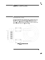
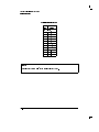
Interconnecting Cables
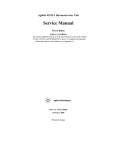
The HP-IB connector allows the synthesizer to be connected to any other
instrument or device on the interface bus. All HP-IB instruments can be
connected with HP-IB cables and adapters. These cables are shown in
Figure 1-1. The adapters are principally extension devices for instruments
that have recessed or crowded HP-IB connectors.
Figure 1-1. HP-IB Connector and Cable
1-3
Getting Started Programming
HP-IB General Information
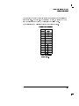
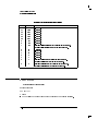
Table 1-1. HP-IB Interface Cables Available
HP-IB Cable
Part Numbers
Lengths
HP 10833A
1m (3.3 ft)
HP 10833B
2m (6.6 ft)
HP 10833C
4m (13.2 ft)
HP 10833D
0.5m (1.6 ft)
As many as fourteen HP-IB instruments can be connected to the synthesizer
(fteen total instruments in the system). The cables can be interconnected
in a \star" pattern (one central instrument, with the HP-IB cables emanating
from that instrument like spokes on a wheel), or in a linear pattern
(like boxcars on a train), or any combination pattern. There are certain
restrictions:
Each instrument must have a unique HP-IB address, ranging from 0 to 30
(decimal). Refer to \Instrument Addresses" in this chapter for information
on setting the synthesizer's HP-IB address.
In a two-instrument system that uses just one HP-IB cable, the cable length
must not exceed 4 meters (13 ft).
When more than two instruments are connected on the bus, the cable
length to each instrument must not exceed 2 meters (6.5 ft) per unit.
The total cable length between all units must not exceed 20 meters (65 ft).
Hewlett-Packard manufactures HP-IB extender instruments (HP models
37201A, 37204A/B) that overcome the range limitations imposed by the
cabling rules. These extenders allow twin-pair cable operation up to 1 km
(3,280 ft), and telephone modem operation over any distance. HP sales and
service oces can provide additional information on the HP-IB extenders.
The codes next to the HP-IB connector, illustrated in Figure 1-1, describe
the HP-IB electrical capabilities of the synthesizer, using IEEE Std. 488-1978
mnemonics (HP-IB, GP-IB, IEEE-488, and IEC-625 are all electrically
equivalent). Briey, the mnemonics translate as follows:
SH1
Source Handshake, complete capability.
AH1
Acceptor Handshake, complete capability.
1-4
Getting Started Programming
HP-IB General Information
T5:
Talker; capable of basic talker, serial poll, and unaddress if
MLA.
TE0
Talker, Extended address; no capability.
L3
Listener, capable of basic listener, and unaddress if MTA.
LE0
Listener, Extended address; no capability.
SR1
Service Request, complete capability.
RL1
Remote Local, complete capability.
PP0
Parallel Poll, no capability.
DC1
Device Clear, complete capability.
DT0
Device Trigger, complete capability.
C0, 1
Controller capability options; C0, no capabilities; C1,
system controller.
E2
Electrical specication indicating open collector outputs.
These codes are described completely in the IEEE Std. 488-1978 document,
published by the Institute of Electrical and Electronic Engineers, Inc., 345
East 47th Street, New York, New York 11017.
Instrument Addresses
Each instrument in an HP-IB network must have a unique address, an integer
ranging in value from 0 to 30. The default address for the synthesizer is 19,
but this can be changed using the 4SHIFT5 4LOCAL5 keys.
1-5
Getting Started Programming
HP-IB General Information
HP-IB Instrument Nomenclature
An HP-IB instrument is categorized as a \listener," \talker," or \controller,"
depending on its current function in the network.
Listener
A listener is a device capable of receiving data or commands from other
instruments. Any number of instruments in the HP-IB network can be
listeners simultaneously.
Talker
A talker is a device capable of transmitting data or commands to other
instruments. To avoid confusion, an HP-IB system allows only one device at a
time to be an active talker.
Controller
A controller is an instrument, typically a computer, capable of managing the
various HP-IB activities. Only one device at a time can be an active controller.
Programming the Synthesizer
The synthesizer can be controlled entirely by a computer (although the
POWER or LINE switch must be operated manually). Several functions
are possible only by computer (remote) control. Computer programming
procedures for the synthesizer involve selecting an HP-IB command
statement, then adding the specic synthesizer (SCPI, HP 8673) programming
codes to that statement to achieve the desired operating conditions.
In the programming explanations that follow, specic examples are included
that are written in a generic dialect of the BASIC language. BASIC was
selected because the majority of HP-IB computers have BASIC language
capability. However, other programming languages can also be used.
1-6
Getting Started Programming
HP-IB General Information
HP-IB Command Statements
Command statements form the nucleus of HP-IB programming; they are
understood by all instruments in the network and, when combined with
the programming language codes, they provide all management and data
communication instructions for the system.
An explanation of the eight fundamental command statements follows.
However, some computers use a slightly dierent terminology, or support an
extended or enhanced version of these commands. Consider the following
explanations as a starting point, but for detailed information consult the
BASIC language reference manual, the I/O programming guide, and the HP-IB
manual for the particular computer used.
Syntax drawings accompany each statement: All items enclosed by a circle or
oval are computer specic terms that must be entered exactly as described;
items enclosed in a rectangular box are names of parameters used in the
statement; and the arrows indicate a path that generates a valid combination
of statement elements.
1-7
Getting Started Programming
HP-IB General Information
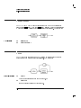
Abort
Abort abruptly terminates all listener/talker activity on the interface bus,
and prepares all instruments to receive a new command from the controller.
Typically, this is an initialization command used to place the bus in a known
starting condition. The syntax is:
where the interface select code is the computer's HP-IB I/O port, which is
typically port 7. Some BASIC examples:
10
ABORT 7
100 IF V>20 THEN ABORT 7
Related statements used
by some computers
ABORTIO (used by HP-80 series computers)
HALT
RESET
1-8
Getting Started Programming
HP-IB General Information
Remote
Remote causes an instrument to change from local control to remote control.
In remote control, the front panel keys are disabled (except for the 4LOCAL5
key and the POWER or LINE switch), and the REMOTE annunciator is lit.
The syntax is:
where the device selector is the address of the instrument appended to the
HP-IB port number. Typically, the HP-IB port number is 7, and the default
address for the synthesizer is 19, so the device selector is 719.
Some BASIC examples
10
REMOTE 7
which prepares all HP-IB instruments for remote operation (although
nothing appears to happen to the instruments until they are addressed to
talk), or
10
REMOTE 719
which aects the HP-IB instrument located at address 19, or
10
REMOTE 719, 721, 726, 715
which eects four instruments that have addresses 19, 21, 26, and 15.
1-9
Getting Started Programming
HP-IB General Information
Local Lockout
LOCAL LOCKOUT can be used in conjunction with REMOTE to disable the
front panel 4LOCAL5 key. With the 4LOCAL5 key disabled, only the controller (or
a hard reset by the POWER switch) can restore local control. The syntax is:
A BASIC example
10
REMOTE 719
20
LOCAL LOCKOUT 7
Local
LOCAL is the complement to REMOTE, causing an instrument to return to
local control with a fully enabled front panel. The syntax is:
Some BASIC examples
10
LOCAL 7
which eects all instruments in the network, or
10
LOCAL 719
for an addressed instrument (address 19).
1-10
Getting Started Programming
HP-IB General Information
Clear
CLEAR causes all HP-IB instruments, or addressed instruments, to assume a
\cleared" condition, with the denition of \cleared" being unique for each
device. For the synthesizer:
1. All pending output-parameter operations are halted.
2. The parser (the software that interprets the programming codes) is reset,
and now expects to receive the rst character of a programming code.
The syntax is:
Some BASIC examples
10
CLEAR 7
to clear all HP-IB instruments, or
10
CLEAR 719
to clear an addressed instrument.
Related statements used
by some computers
RESET
CONTROL
SEND
The preceding statements are primarily management commands that do not
incorporate programming codes. The following two statements do incorporate
programming codes, and are used for data communication.
1-11
Getting Started Programming
HP-IB General Information
Output
OUTPUT is used to send function commands and data commands from the
controller to the addressed instrument. The syntax is:
where USING is a secondary command that formats the output in a particular
way, such as a binary or ASCII representation of numbers. The USING
command is followed by \image items" that precisely dene the format of the
output; these image items can be a string of code characters, or a reference
to a statement line in the computer program. Image items are explained in
the programming codes where they are needed. Notice that this syntax is
virtually identical to the syntax for the ENTER statement that follows.
1-12
Getting Started Programming
HP-IB General Information
A BASIC example
Related statements used
by some computers
100
OUTPUT 719; "programming codes"
CONTROL
CONVERT
IMAGE
IOBUFFER
TRANSFER
1-13
Getting Started Programming
HP-IB General Information
Enter
ENTER is the complement of OUTPUT, and is used to transfer data from the
addressed instrument to the controller. The syntax is:
ENTER is always used in conjunction with OUTPUT, such as:
100 OUTPUT 719; " . . . programming codes . . . "
110 ENTER 719; " . . . response data . . . "
ENTER statements are commonly formatted, which requires the secondary
command USING and the appropriate image items. The most-used image
items involve end-of-line (end or identify) suppression, binary inputs, and
literal inputs.
Example
100 ENTER 719 USING "#, B"; A, B, C
suppresses the EOI sequence (#), and indicates that variables A, B, and C
are to be lled with binary (B) data. As another example,
100 ENTER 719 USING "#, 123A"; A$
suppresses EOI, and indicates that string variable A$ is to be lled with
123 bytes of literal data (123A).
1-14
Getting Started Programming
HP-IB General Information
NOTE
Be careful when using byte-counting image speciers. If the requested number of bytes does not
match the actual number available, data might be lost, or the program might enter an endless wait
state.
The suppression of the EOI sequence is frequently necessary to prevent a
premature termination of the data input. When not specied, the typical
EOI termination occurs when an ASCII LF (line feed) is received. However,
the LF bit pattern could coincidentally occur randomly in a long string of
binary data, where it might cause a false termination. Also, the bit patterns
for the ASCII CR (carriage return), comma, or semicolon might cause a false
termination. Suppression of the EOI causes the computer to accept all bit
patterns as data, not commands, and relies on the HP-IB EOI (end or identify)
line for correct end-of-data termination.
Related statements used
by some computers
CONVERT
IMAGE
IOBUFFER
ON TIMEOUT
SET TIMEOUT
TRANSFER
This completes the \HP-IB Command Statements" subsection. The following
material explains the SCPI programming codes, and shows how they are used
with the OUTPUT and ENTER HP-IB command statements.
1-15
Getting Started with SCPI
This section of Chapter 1 describes the use of the Standard Commands for
Programmable Instruments language (SCPI). This section explains how to use
SCPI commands in general. This section presents only the basics of SCPI.
If you want to explore the topic in greater depth, see the paragraph titled,
\Related Documents."
1-16
Denitions of Terms
You need a general understanding of the terms listed below before you
continue.
controller
A controller is any computer used to communicate with a
SCPI instrument. A controller can be a personal computer,
a minicomputer, or a plug-in card in a card cage. Some
intelligent instruments can
also function as controllers.
instrument
An instrument is any device that implements SCPI. Most
instruments are electronic measurement or stimulus devices,
but this is not a requirement. Similarly, most instruments
use an HP-IB interface for communication. The same
concepts apply regardless of the instrument function or the
type of interface used.
program
A program message is a combination of one or more
properly formatted SCPI commands. Program messages
message
always go from a controller to an instrument. Program
messages tell the instrument how to make measurements
and output signals.
response
A response message is a collection of data in specic SCPI
formats. Response messages always go from an instrument
message
to a controller or listening instrument. Response messages
tell the controller about the internal state of the instrument
and about measured values.
command
A command is an instruction in SCPI. You combine
commands to form messages that control instruments. In
general, a command consists of mnemonics (keywords),
parameters, and punctuation.
query
A query is a special type of command. Queries instruct the
instrument to make response data available to the controller.
Query mnemonics always end with a question mark.
1-17
Getting Started Programming
Denitions of Terms
Standard Notation
This section uses several forms of notation that have specic meaning.
Command Mnemonics
Many commands have both a long and a short form, and you must use either
one or the other (SCPI does not accept a combination of the two). Consider
the FREQuency command,for example. The short form is FREQ and the long
form is FREQUENCY (this notation style is a shorthand to document both the
long and short form of commands). SCPI is not case sensitive, so fREquEnCy
is just as valid as FREQUENCY, but FREQ and FREQUENCY are the only valid
forms of the FREQuency command.
Angle Brackets
Angle brackets indicate that the word or words enclosed represent something
other than themselves. For example, <new line> represents the ASCII
character with the decimal value 10. Similarly, <^END> means that EOI is
asserted on the HP-IB interface. Words in angle brackets have much more
rigidly dened meaning than words used in ordinary text. For example, this
section uses the word \message" to talk about messages generally. But the
bracketed words <program message> indicate a precisely dened element of
SCPI. If you need them, you can nd the exact denitions of words such as
<program message> in a syntax diagram.
How to Use Examples
It is important to understand that programming with SCPI actually requires
knowledge of two languages. You must know the programming language of
your controller (BASIC, C, Pascal) as well as the language of your instrument
(SCPI). The semantic requirements of your controller's language determine
how the SCPI commands and responses are handled in your application.
1-18
Getting Started Programming
Denitions of Terms
Command Examples
Command examples look like this:
:FREQuency:CW?
This example tells you to put the string :FREQuency:CW? in the output
statement appropriate to your application programming language. If you
encounter problems, study the details of how the output statement handles
message terminators such as <new line>. If you are using simple OUTPUT
statements in HP BASIC, this is taken care of for you. In HP BASIC, you type:
OUTPUT 719;":FREQuency:CW?"
Command examples do not show message terminators because they are used
at the end of every program message. \Details of Commands and Responses,"
discusses message terminators in more detail.
Response Examples
Response examples look like this:
3.000000000000E+009
These are the characters you would read from an instrument after
sending a query command. To actually pull them from the instrument into
the controller, use the input statement appropriate to your application
programming language. If you have problems, study the details of how the
input statement operates. In particular, investigate how the input statement
handles punctuation characters such as comma and semicolon, and how it
handles <new line> and EOI. To enter the previous response in HP BASIC,
you type:
ENTER 719;CW_frequency
Response examples do not show response message terminators because
they are always <new line> <^END>. These terminators are typically
automatically handled by the input statement. The paragraph titled \Details
of Commands and Responses," later in this chapter, discusses message
terminators in more detail.
1-19
Essentials for Beginners
This section discusses elementary concepts critical to rst-time users of SCPI.
Read and understand this section before continuing. This section includes the
following topics:
Program and Response
These paragraphs introduce the basic types
Messages
of messages sent between instruments and
controllers.
Subsystem Command Trees These paragraphs describe the tree structure
used in subsystem commands.
Reading Instrument Errors
These paragraphs explain how to read
and print an instrument's internal error
messages.
Example Programs
These paragraphs contain two simple
measurement programs that illustrate basic
SCPI programming principles.
1-20
Getting Started Programming
Essentials for Beginners
Program and Response Messages
To understand how your instrument and controller communicate using
SCPI, you must understand the concepts of program and response messages.
Program messages are the formatted data sent from the controller to the
instrument. Conversely, response messages are the formatted data sent from
the instrument to the controller. Program messages contain one or more
commands, and response messages contain one or more responses.
The controller may send commands at any time, but the instrument sends
responses only when specically instructed to do so. The special type of
command used to instruct the instrument to send a response message is the
query. All query mnemonics end with a question mark. Queries return either
measured values or internal instrument settings. Any internal setting that can
be programmed with SCPI can also be queried.
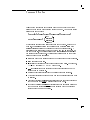
Forgiving Listening and
Precise Talking
SCPI uses the concept of forgiving listening and precise talking outlined in
IEEE 488.2.
Forgiving listening means that instruments are very exible in accepting
various command and parameter formats. For example, the synthesizer
accepts either :POWer:STATe ON or :POWer:STATe 1 to turn RF output on.
Precise talking means that the response format for a particular query is
always the same. For example, if you query the power state when it is on
(using :POWer:STATe?), the response is always 1, regardless of whether you
previously sent :POWer:STATe 1 or :POWer:STATe ON.
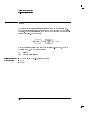
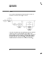
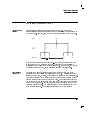
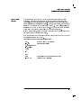
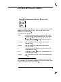
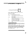
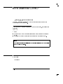
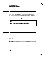
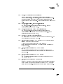
Types of Commands
Commands can be separated into two groups, common commands and
subsystem commands.
Common commands are generally not measurement related. They are
used to manage macros, status registers, synchronization, and data storage.
Common commands are easy to recognize because they all begin with an
asterisk, such as *IDN?, *OPC, and *RST. Common commands are dened by
IEEE 488.2.
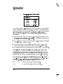
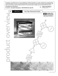
Subsystem commands include all measurement functions and some general
purpose functions. Subsystem commands are distinguished by the colon used
between keywords, as in :FREQuency:CW?. Each command subsystem is a
1-21
Getting Started Programming
Essentials for Beginners
set of commands that roughly corresponds to a functional block inside the
instrument. For example, the POWer subsystem contains commands for power
generation, while the STATus subsystem contains commands for accessing
status registers.
Figure 1-2. SCPI Command Types
The remaining paragraphs in this subsection discuss subsystem commands in
more detail. Remember, some commands are implemented in one instrument
and not in another, depending on its measurement function.
1-22
Getting Started Programming
Essentials for Beginners
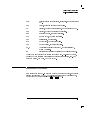
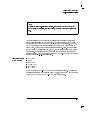
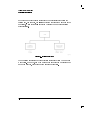
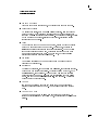
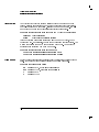
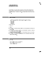
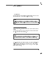
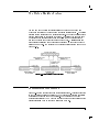
Subsystem Command Trees
The Command Tree
Structure
Most programming tasks involve subsystem commands. SCPI uses a
hierarchical structure for subsystem commands similar to the le systems on
most computers. In SCPI, this command structure is called a command tree.
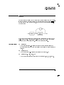
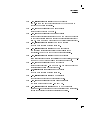
Figure 1-3. A Simplied Command Tree
In the command tree shown in Figure 1-3, the command closest to the top
is the root command, or simply the root. Notice that you must follow a
particular path to reach lower level subcommands. For example, if you wish
to access the GG command, you must follow the path AA to BB to GG.
Paths Through the
Command Tree
To access commands in dierent paths in the command tree, you must
understand how an instrument interprets commands. A special part of the
instrument rmware, a parser, decodes each message sent to the instrument.
The parser breaks up the message into component commands using a set of
rules to determine the command tree path used. The parser keeps track of
the current path, the level in the command tree where it expects to nd the
next command you send. This is important because the same keyword may
appear in dierent paths. The particular path you use determines how the
keyword is interpreted. The following rules are used by the parser:
1-23
Getting Started Programming
Essentials for Beginners
Power On and Reset
After power is cycled or after *RST, the current path is set to the root.
Message Terminators
A message terminator, such as a <new line> character, sets the current
path to the root. Many programming languages have output statements
that send message terminators automatically. The paragraph titled, \Details
of Commands and Responses," later in this chapter, discusses message
terminators in more detail.
Colon
When it is between two command mnemonics, a colon moves the current
path down one level in the command tree. For example, the colon in
MEAS:VOLT species that VOLT is one level below MEAS. When the colon
is the rst character of a command, it species that the next command
mnemonic is a root level command. For example, the colon in :INIT
species that INIT is a root level command.
Semicolon
A semicolon separates two commands in the same message without
changing the current path.
Whitespace
Whitespace characters, such as <tab> and <space>, are generally ignored.
There are two important exceptions. Whitespace inside a keyword, such
as :FREQ uency, is not allowed. You must use white space to separate
parameters from commands. For example, the <space> between LEVel
and 6.2 in the command :POWer:LEVel 6.2 is mandatory. Whitespace
does not aect the current path.
Commas
If a command requires more than one parameter, you must separate
adjacent parameters using a comma. Commas do not aect the current
path.
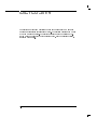
Common Commands
Common commands, such as *RST, are not part of any subsystem. An
instrument interprets them in the same way, regardless of the current path
setting.
1-24
Getting Started Programming
Essentials for Beginners
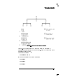
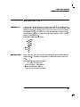
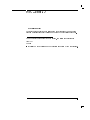
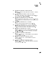
Figure 1-4. Proper Use of the Colon and Semicolon
Figure 1-4 shows examples of how to use the colon and semicolon to
navigate eciently through the command tree. Notice how proper use of the
semicolon can save typing.
Sending this message:
:AA:BB:EE; FF; GG
Is the same as sending these three messages:
:AA:BB:EE
:AA:BB:FF
:AA:BB:GG
1-25
Getting Started Programming
Essentials for Beginners
More About Commands
Query and Event
Commands
You can query any value that you can set. For example, the presence of the
synthesizer FREQuency:STEP command implies that a FREQuency:STEP?
also exists. If you see a command ending with a question mark, it is a query
only command. Some commands are events, and cannot be queried. An
event has no corresponding setting if it causes something to happen inside
the instrument at a particular instant.
Implied Commands
Implied commands appear in square brackets. If you send a subcommand
immediately preceding an implied command, but do not send the implied
command, the instrument assumes you intend to use the implied command,
and behaves just as if you had sent it. Note that this means the instrument
expects you to include any parameters required by the implied command.
The following example illustrates equivalent ways to program the synthesizer
using explicit and implied commands.
Example Synthesizer commands with and without an implied command:
FREQuency:STEP:INCRement 1 using explicit commands
FREQuency:STEP 1
using implied commands
Optional Parameters
Optional parameter names are enclosed in square brackets. If you do not send
a value for an optional parameter, the instrument chooses a default value.
The instrument's command dictionary documents the values used for optional
parameters.
1-26
Getting Started Programming
Essentials for Beginners
Program Message Examples
The following parts of the synthesizer SCPI command set will be used to
demonstrate how to create complete SCPI program messages:
:FREQuency
[:CW]
:STEP
:POWER
[:LEVel]
Example 1
"FREQuency:CW 5 GHZ; STEP 2 GHZ"
The command is correct and will not cause errors. It is equivalent to
sending:
"FREQuency:CW 5 GHZ; :FREQuency:STEP 2 GHZ".
Example 2
"FREQuency 5 GHZ; :STEP 2 GHZ"
This command results in a command error. The command makes use of
the default [:CW] node. When using a default node, there is no change to
the current path position. Since there is no command "STEP" at the root,
an error results. A correct way to send this is:
"FREQ 5 GHZ; FREQ:STEP 2 GHZ"
or as in example 1.
1-27
Getting Started Programming
Essentials for Beginners
Example 3
"FREQuency:STEP 1 GHZ; FREQuency:CW 5 GHZ"
This command results in a command error. The FREQ:CW portion of the
command is missing a leading colon. The path level is dropped at each
colon until it is in the FREQ:STEP subsystem. So when the FREQ:CW
command is sent, it causes confusion because no such node occurs in the
FREQ:STEP subsystem. By adding a leading colon, the current path is
reset to the root. The corrected command is:
"FREQuency:STEP 1 GHZ; :FREQuency:CW 5 GHZ".
Example 4
"FREQ 5 GHZ; POWER 4 DBM"
Notice that in this example the keyword short form is used. The
command is correct. It utilizes the default nodes of [:CW] and [:LEVEL].
Since default nodes do not aect the current path, it is not necessary to
use a leading colon before POWER.
1-28
Getting Started Programming
Essentials for Beginners
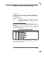
Reading Instrument Errors
When debugging a program, you may want to know if an instrument error
has occurred. Some instruments can display error messages on their front
panels. If your instrument cannot do this, you can put the following code
segment in your program to read and display error messages.
10 !
20 ! The rest of your
30 ! variable declarations
40 ! Assign @box to 719
50 DIM Err_msg$[75]
60 INTEGER Err_num
70 !
80 ! Part of your program
90 ! that generates errors
100 !
110 !
200 REPEAT
210 OUTPUT @Box;":SYST:ERR?"
220 ! Query instrument error
230 ENTER @Box;Err_num,Err_msg$
240 ! Read error #, message
250 PRINT Err_num,Err_msg$
260 ! Print error message
270 UNTIL Err_num = 0
280 ! Repeat until no errors
290 !
300 ! The rest of your program
310 !
1-29
Details of Commands and Responses
This section describes the syntax of SCPI commands and responses. It
provides many examples of the data types used for command parameters and
response data. The following topics are explained:
Program Message These paragraphs explain how to properly construct
Syntax
the messages you send from the computer to
instruments.
Response Message These paragraphs discuss the format of messages sent
from instruments to the computer.
Syntax
SCPI Data Types
These paragraphs explain the types of data contained
in program and response messages.
1-30
Getting Started Programming
Details of Commands and Responses
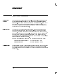
Program Message Syntax
These program messages contain commands combined with appropriate
punctuation and program message terminators.
Figure 1-5. Simplied Program Message Syntax
As Figure 1-5 shows, you can send common commands and subsystem
commands in the same message. If you send more than one command in the
same message, you must separate them with a semicolon. You must always
end a program message with one of the three program message terminators
shown in Figure 1-5. Use <new line>, <^END>, or <new line> <^END>
as the program message terminator. The word <^END> means that EOI is
asserted on the HP-IB interface at the same time the preceding data byte is
sent. Most programming languages send these terminators automatically.
For example, if you use the HP BASIC OUTPUT statement, <new line> is
automatically sent after your last data byte. If you are using a PC, you can
usually congure the system to send whatever terminator you specify.
1-31
Getting Started Programming
Details of Commands and Responses
SCPI Subsystem Command Syntax
Figure 1-6. SCPI Simplied Subsystem Command Syntax
As Figure 1-6 shows, there must be a <space> between the last command
mnemonic and the rst parameter in a subsystem command. This is one of
the few places in SCPI where <space> is required. Note that if you send
more than one parameter with a single command, you must separate adjacent
parameters with a comma. Parameter types are explained later in this
subsection.
1-32
Getting Started Programming
Details of Commands and Responses
Common Command Syntax
Figure 1-7. Simplied Common Command Syntax
As with subsystem commands, use a <space> to separate a command
mnemonic from subsequent parameters. Separate adjacent parameters with a
comma. Parameter types are explained later in this subsection.
1-33
Getting Started Programming
Details of Commands and Responses
Response Message Syntax
Figure 1-8. Simplied Response Message Syntax
Response messages can contain both commas and semicolons as separators.
When a single query command returns multiple values, a comma separates
each data item. When multiple queries are sent in the same message,
the groups of data items corresponding to each query are separated by a
semicolon. For example, the ctitious query :QUERY1?:QUERY2? might
return a response message of:
<data1>,<data1>;<data2>,<data2>
Response data types are explained later in this subsection. Note that
<new line><^END> is always sent as a response message terminator.
1-34
Getting Started Programming
Details of Commands and Responses
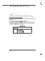
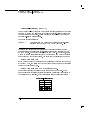
SCPI Data Types
These paragraphs explain the data types available for parameters and
response data. They list the types available and present examples for each
type. SCPI denes dierent data formats for use in program messages
and response messages. It does this to accommodate the principle of
forgiving listening and precise talking. Recall that forgiving listening means
instruments are exible, accepting commands and parameters in various
formats. Precise talking means an instrument always responds to a particular
query in a predened, rigid format. Parameter data types are designed to be
exible in the spirit of forgiving listening. Conversely, response data types
are dened to meet the requirements of precise talking.
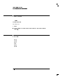
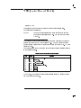
Table 1-2. SCPI Data Types
Parameter Types Response Data Types
Numeric
Real or Integer
Extended Numeric
Integer
Discrete
Discrete
Boolean
Numeric Boolean
String
String
Block
Denite Length Block
Indenite Length Block
Non-decimal Numeric Hexadecimal
Octal
Binary
Notice that each parameter type has one or more corresponding response
data types. For example, a setting that you program using a numeric
parameter returns either real or integer response data when queried.
Whether real or integer response data is returned depends on the instrument
used. However, precise talking requires that the response data type be clearly
dened for a particular instrument and query. The instrument command
1-35
Getting Started Programming
Details of Commands and Responses
dictionary in Chapter 2 generally contains information about data types for
individual commands. The following paragraphs explain each parameter and
response data type in more detail.
Parameter Types
Numeric Parameters
Numeric parameters are used in both subsystem commands and common
commands. Numeric parameters accept all commonly used decimal
representations of numbers including optional signs, decimal points, and
scientic notation.
If an instrument setting programmed with a numeric parameter can only
assume a nite number of values, the instrument automatically rounds
the parameter. For example, if an instrument has a programmable output
impedance of 50 or 75 ohms, and you specied 76.1 for output impedance,
the value is rounded to 75. If the instrument setting can only assume integer
values, it automatically rounds the value to an integer. For example, sending
*ESE 10.123 is the same as sending *ESE 10.
Examples of numeric parameters:
100
100.
-1.23
4.56e<space>3
-7.89E-01
+256
.5
1-36
no decimal point required
fractional digits optional
leading signs allowed
space allowed after e in exponentials
use either E or e in exponentials
leading + allowed
digits left of decimal point optional
Getting Started Programming
Details of Commands and Responses
Extended Numeric
Parameters
Most subsystems use extended numeric parameters to specify physical
quantities. Extended numeric parameters accept all numeric parameter
values and other special values as well. All extended numeric parameters
accept MAXimum and MINimum as values. Other special values, such as UP and
DOWN may be available as documented in Chapter 2. Note that MINimum and
MAXimum can be used to set or query values. The query forms are useful for
determining the range of values allowed for a given parameter.
In some instruments, extended numeric parameters accept engineering unit
suxes as part of the parameter value.
Note that extended numeric parameters are not used for common commands
or STATus subsystem commands.
Examples of extended numeric parameters:
100.
any simple numeric values
-1.23
largest valid setting
4.56e<space>3
-7.89E-01
+256
.5
MAX
MIN
-100 mV
valid setting nearest negative innity
negative 100 millivolts
1-37
Getting Started Programming
Details of Commands and Responses
Discrete Parameters
Use discrete parameters to program settings that have a nite number of
values. Discrete parameters use mnemonics to represent each valid setting.
They have a long and a short form, just like command mnemonics. You can
used mixed upper and lower case letters for discrete parameters.
Examples of discrete parameters used with the ALC:SOURce subsystem:
INTernal internal leveling
DIODe
external diode detector leveling
Although discrete parameters values look like command keywords, do not
confuse the two. In particular, be sure to use colons and spaces properly. Use
a colon to separate command mnemonics from each other. Use a space to
separate parameters from command mnemonics.
Examples of discrete parameters in commands:
100 OUTPUT @Source;"POWer:ALC:SOURce INT"
100 OUTPUT @Source;"POWer:ALC:SOURce DIODe"
Boolean Parameters
Boolean parameters represent a single binary condition that is either true or
false. There are only four possible values for a Boolean parameter.
Examples of Boolean parameters:
ON
OFF
1
0
1-38
Boolean TRUE, upper/lower case allowed
Boolean FALSE, upper/lower case allowed
Boolean TRUE
Boolean FALSE
Getting Started Programming
Details of Commands and Responses
Response Data Types
Real Response Data
A large portion of all measurement data are formatted as real response data.
Real response data are decimal numbers in either xed decimal notation or
scientic notation. In general, you do not need to worry about the rules for
formatting real data, or whether xed decimal or scientic notation is used.
Most high level programming languages that support instrument I/O handle
either type transparently.
Examples of real response data:
1.23E+0
-1.0E+2
+1.0E+2
0.5E+0
1.23
-100.0
+100.0
0.5
Integer Response Data
Integer response data are decimal representations of integer values including
optional signs. Most status register related queries return integer response
data.
Examples of integer response data:
0
+100
-100
256
signs are optional
leading + sign allowed
leading sign allowed
never any decimal point
1-39
Getting Started Programming
Details of Commands and Responses
Discrete Response Data
Discrete response data are similar to discrete parameters. The main dierence
is that discrete response data return only the short form of a particular
mnemonic, in all upper case letters.
Examples of discrete response data:
INTernal
DIODe
String Response Data
level internally
level using an external diode
String response data are similar to string parameters. The main dierence is
that string response data use only double quotes as delimiters, rather than
single quotes. Embedded double quotes may be present in string response
data. Embedded quotes appear as two adjacent double quotes with no
characters between them.
Examples of string response data:
"This IS valid"
"SO IS THIS "" "
"I said, ""Hello!"""
1-40
Programming Typical Measurements
This section illustrates how the general SCPI concepts presented in previous
sections apply to programming real measurements. To introduce you to
programming with SCPI, we must list the commands for the synthesizer. We
will begin with a simplied example.
Using the Example Programs
The example programs are interactive. They require active participation by
the operator. If you desire to get an understanding of the principles without
following all of the instructions, read the \Program Comments" paragraphs to
follow the programmed activity.
The HP-IB select code is assumed to be preset to 7. All example programs in
this section expect the synthesizer's HP-IB address to be decimal 19.
To nd the present HP-IB address use the front panel.
Press 4SHIFT5 4LOCAL5.
The active entry area indicates the present decimal address. If the number
displayed is not 19, press 4195 4ENTER5 to reset it to 19.
Now check that the interface language is set to SCPI. Press 4SPECIAL5 4155
4ENTER5. The selected interface language is then shown, use the up and down
keys to change the language.
1-41
Getting Started Programming
Programming Typical Measurements
HP-IB Check, Example Program 1
This rst program is to verify that the HP-IB connections and interface are
functional. Connect a controller to the synthesizer via an HP-IB cable. Clear
and reset the controller and type in the following program:
10
Synthesizer =719
20
ABORT 7
30
LOCAL Synthesizer
40
CLEAR Synthesizer
50
REMOTE Synthesizer
60
CLS
70
PRINT "The synthesizer should now be in REMOTE."
80
PRINT "Verify that the 'RMT' annunciator is on."
90
END
Run the program and verify that the RMT annunciator is lit on the
synthesizer. If it is not, verify that the synthesizer address is set to 19 and
that the interface cable is properly connected.
If the controller display indicates an error message, it is possible that the
program was entered in incorrectly. If the controller accepts the REMOTE
statement but the synthesizer RMT annunciator does not turn on, refer to the
service guide to nd the trouble shooting information.
Program Comments
10:
20:
30:
40:
50:
60:
70:
1-42
Set up a variable to contain the HP-IB address of the source.
Abort any bus activity and return the HP-IB interfaces to their reset
states.
Place the synthesizer into LOCAL to cancel any Local Lockouts that
may have been setup.
Reset the synthesizer's parser and clear any pending output from the
source. Prepare the synthesizer to receive new commands.
Place the synthesizer into REMOTE.
Clear the display of the computer.
Print a message to the computer's display.
Getting Started Programming
Programming Typical Measurements
Local Lockout Demonstration, Example Program 2
When the synthesizer is in REMOTE mode, all the front panel keys are
disabled except the LOCAL key. But, when the LOCAL LOCKOUT command
is set on the bus, even the LOCAL key is disabled. The LOCAL command,
executed from the controller, is then the only way to return all (or selected)
instruments to front panel control.
Continue example program 1. Delete line 90 END and type in the following
commands:
90
100
110
120
130
140
150
160
170
180
190
200
210
220
230
240
PRINT "Verify that all keys are ignored,
except the 'LOCAL' key."
PRINT "Verify that 'LOCAL' causes the
RMT annunciator to go OFF."
PRINT " ..... press CONTINUE"
PAUSE
REMOTE Synthesizer
LOCAL LOCKOUT 7
PRINT
PRINT "Synthesizer should now be in LOCAL LOCKOUT mode."
PRINT "Verify that all keys (including 'LOCAL')
have no effect."
PRINT " ..... press CONTINUE"
PAUSE
LOCAL Synthesizer
PRINT
PRINT "Synthesizer should now be in LOCAL mode."
PRINT "Verify that the synthesizer's keyboard
is functional."
END
1-43
Getting Started Programming
Programming Typical Measurements
Program Comments
90 to 120:
130:
140:
150 to 190:
200:
210 to 230:
1-44
Print a message on the computer's display, then pause.
Place the synthesizer into REMOTE.
Place the synthesizer into LOCAL LOCKOUT mode.
Print a message on the computer's display, then pause.
Return the synthesizer to local control.
Print a message on the computer's display.
Getting Started Programming
Programming Typical Measurements
Internally Leveled CW Signal, Example Program 3
In the following example, an internally leveled, CW signal is generated at a
frequency of 2.000203 GHz with a power level of 02.1 dBm. Clear and reset
the controller and type in the following program:
10
Synthesizer=719
20
ABORT 7
30
LOCAL 7
40
CLEAR Synthesizer
50
REMOTE Synthesizer
60
OUTPUT Synthesizer;"*RST"
70
OUTPUT Synthesizer;"POW:ALC:SOUR INT"
80
OUTPUT Synthesizer;"FREQuency 2.000203GHZ"
90
OUTPUT Synthesizer;"POWer:LEVel -2.1 DBM"
100 OUTPUT Synthesizer;"OUTP:STATe ON"
110 END
Run the program.
Program Comments
10:
20 to 50:
60:
70:
80:
90:
100:
Assign the synthesizer's HP-IB address to a variable.
Abort any HP-IB activity and initialize the HP-IB interface.
Set the synthesizer to its initial state for programming. The
*RST state is the same as the PRESET state.
Enable internal leveling.
Set the frequency to 2.000203 GHz.
Set the synthesizer's power level to 02.1 dBm.
Turn the RF output on.
1-45
Getting Started Programming
Programming Typical Measurements
Level Correction Routine, Example Program 4
The following example demonstrates how to gather level correct data
externally, then load the collected data into one of the synthesizer level
correct tables. Clear and reset the controller and type in the following
program:
10
20
30
40
50
60
70
80
90
100
110
120
130
140
150
160
170
180
190
200
210
220
230
240
250
260
270
280
1-46
Synthesizer=719
Power_meter=713
ABORT 7
LOCAL 7
CLEAR Synthesizer
REMOTE Synthesizer
CLS
OUTPUT Synthesizer;"*RST"
OUTPUT Power_meter;"*RST"
DIM Frequencies(1:401)
DIM Losses(1:401)
PRINT "CHOOSE THE START FREQUENCY IN GHZ (1.654321 FOR
EXAMPLE)"
ENTER KBD;Start_freq
PRINT "CHOOSE THE STOP FREQUENCY IN GHZ (15.123456 FOR
EXAMPLE)"
ENTER KBD;Stop_freq
PRINT "CHOOSE THE NUMBER OF POINTS (2 TO 401)"
ENTER KBD;Points
PRINT "CHOOSE THE LEVEL CORRECTION TABLE TO STORE DATA
INTO (1 TO 4)"
ENTER KBD;Table_num
PRINT "CHOOSE THE SYNTHESIZER POWER LEVEL TO USE
DURING ";
PRINT "THE LEVEL CORRECTION"
PRINT "(-3.32 FOR EXAMPLE)"
ENTER KBD;Power_level
OUTPUT Synthesizer; "POW ";Power_level
OUTPUT Power_meter; "FM 32 EN"
OUTPUT Power_meter; "TR0"
Step_freq=(Stop_freq-Start_freq)/(Points-1)
Current_freq=Start_freq
Getting Started Programming
Programming Typical Measurements
290 FOR I=1 TO Points
300
Frequencies(I)=Current_freq
310
OUTPUT Synthesizer; "FREQ ";Current_freq;" GHZ"
320
OUTPUT Power_meter; "FR ";Current_freq;" GZ"
330
OUTPUT Power_meter; "TR2"
340
WAIT 5
350
ENTER Power_meter;Meter_reading
360
Losses(I)=Power_level-Meter_reading
370
Current_freq=Current_freq+Step_freq
380 NEXT I
390 OUTPUT Synthesizer; "MEM:TABL:SEL
FDAT";TRIM$(VAL$(Table_num))
400 !
410 ! Store frequencies
420 !
430 OUTPUT Synthesizer; "MEM:TABL:FREQ ";
440 FOR I=1 TO Points
450
OUTPUT Synthesizer;Frequencies(I);"GHZ";
460
IF I<Points THEN OUTPUT Synthesizer;",";
470 NEXT I
480 OUTPUT Synthesizer USING "/"
490 !
500 ! Store losses
510 !
520 OUTPUT Synthesizer; "MEM:TABL:LOSS ";
530 FOR I=1 TO Points
540
OUTPUT Synthesizer;Losses(I);
550
IF I<Points THEN OUTPUT Synthesizer;",";
560 NEXT I
570 OUTPUT Synthesizer USING "/"
580 PRINT "END OF PROGRAM"
590 END
Run the program.
Program Comments
10:
20:
30 to 60:
70:
Assign the synthesizer's HP-IB address to a variable.
Assign the power meter's HP-IB address to a variable.
Abort any HP-IB activity and initialize the HP-IB interface.
Clear the computer's display.
1-47
Getting Started Programming
Programming Typical Measurements
80:
90:
100:
110:
120:
130:
140:
150:
160:
170:
180:
190:
200 to 220:
230:
240:
250:
260:
270:
280:
300:
310:
320:
330:
1-48
Set the synthesizer to its initial state for programming.
Set the power meter to its initial state for programming.
Dimension frequency array.
Dimension correction factor array.
Print a message on the computer display for entering the start
frequency.
Enter start frequency into variable Start freq.
Print a message on the computer display for entering the stop
frequency.
Enter stop frequency into variable Stop freq.
Print a message for entering the number of frequency points to
measure.
Enter number of measurement points into variable Points.
Print a message on the computer display for entering the
desired correction table number.
Enter correction table number into variable Table num.
Print a message on the computer display for entering the
power level.
Enter power level into variable Power level.
Set Synthesizer's power level to the entered value.
Set number of averages.
Set power meter to trigger hold mode.
Calculate the frequency step.
Set variable Current freq equal to the start frequency set by
variable Start freq.
Store current frequency into the Frequencies array.
Set Synthesizer to the current frequency.
Set power meter frequency to the current frequency.
Set power meter to trigger with delay.
Getting Started Programming
Programming Typical Measurements
340:
350:
360:
370:
390:
430:
450:
460:
480:
520:
540:
550:
570:
Wait ve seconds for power meter to stabilize.
Enter current power meter reading into variable
Meter reading.
Store the correction factor into the Losses array.
Increment the current frequency to the next frequency point to
measure.
Select a table for data storage.
Command the synthesizer to load the following frequency
points into table.
Add a frequency point into the table.
Add a data separator (comma).
Add a line feed.
Command the synthesizer to load the following correction
factors into table.
Add a correction factor into the table.
Add a data separator (comma).
Add a line feed.
1-49
Getting Started Programming
Programming Typical Measurements
Saving and Recalling States, Example Program 5
The complete front panel state may be saved for later use in non-volatile
memories called registers 0 through 9. This can be done remotely as a part of
a program. Clear and reset the controller and type in the following program:
10
20
30
40
50
60
70
80
90
100
110
120
130
140
150
160
170
180
190
200
210
220
230
Synthesizer=719
ABORT 7
LOCAL 7
CLEAR Synthesizer
REMOTE Synthesizer
CLS
OUTPUT Synthesizer;"*RST;FREQ: 4GHZ;POW:LEV -3DBM
;OUTP:STAT ON"
OUTPUT Synthesizer;"*SAV 1"
CLS
PRINT "A Synthesizer state has been saved in REGISTER 1."
OUTPUT Synthesizer;"*RST;FREQ:CW 1.23456GHZ;:POW:LEV -1DBM"
OUTPUT Synthesizer;"*SAV 2"
PRINT "A CW state has been saved in REGISTER 2."
PRINT "..... Press Continue"
PAUSE
OUTPUT Synthesizer;"*RCL 1"
PRINT "Register 1 recalled. Verify Synthesizer output power."
PRINT "Press Continue."
PAUSE
OUTPUT Synthesizer;"*RCL 2"
PRINT "Register 2 recalled."
PRINT "Verify Synthesizer is in CW mode."
END
Run the program.
1-50
Getting Started Programming
Programming Typical Measurements
Program Comments
10:
20 to 50:
60:
70:
Assign the synthesizer's HP-IB address to a variable.
Abort any HP-IB activity and initialize the HP-IB interface.
Clear the computer's display.
Set up a Synthesizer state. Note the combination of several
commands into a single message. This single line is equivalent
to the following lines :
OUTPUT Synthesizer;"*RST"
OUTPUT Synthesizer;"FREQ 4GHZ"
OUTPUT Synthesizer;"POW:LEV -3DBM"
OUTPUT Synthesizer;"OUTP:STAT ON"
80:
90:
100:
110:
Save this state into storage register 1.
Clear the computer display.
Print a message on the computer display.
Setup the synthesizer for a CW state. Note the combination of
several commands into a single message. This single line is
equivalent to the following lines :
OUTPUT Source;"*RST"
OUTPUT Source;"FREQ:CW 1.23456 GHZ"
OUTPUT Source;"POW:LEV -1DBM"
120:
130 to 150:
160:
170 to 190:
200:
Save this state into storage register 2.
Print a message on the computer display and pause.
Recall the instrument state from register 1.
Print a message on the computer display and pause.
Recall the instrument state from register 2. It should contain
the CW state.
210 and 220: Print messages on the computer display.
1-51
Related Documents
IEEE Standard 488.1-1987, IEEE Standard Digital Interface for
Programmable Instrumentation. The International Institute of Electrical and
Electronics Engineers, New York, NY, 1987.
This standard denes the technical details required to design and build an
HP-IB interface (IEEE 488.1). This standard contains electrical specications
and information on protocol that is beyond the needs of most programmers.
However, it can be useful to clarify formal denitions of certain terms used in
related documents.
IEEE Standard 488.2-1987, IEEE Standard Codes, Formats, Protocols,
and Common Commands For Use with ANSI/IEEE Std 488.1-1987. The
International Institute of Electrical and Electronics Engineers, New York, NY,
1987.
This document describes the underlying message formats and data types
used in SCPI. It is intended more for instrument rmware engineers than
for instrument user/programmers. However, you may nd it useful if you
need to know the precise denition of certain message formats, data types, or
common commands.
NOTE
To obtain a copy of either of these documents, write to:
The Institute of Electrical and Electronics Engineers, Inc. 345 East 47th Street New York, NY 10017
USA
BASIC 5.0/5.1 Interfacing Techniques. Vol. 2, Specic Interfaces.
Hewlett-Packard Company 1987.
This HP BASIC manual contains a good non-technical description of the HP-IB
(IEEE 488.1) interface in Chapter 12, \The HP-IB Interface." Subsequent
revisions of HP BASIC may use a slightly dierent title for this manual or
1-52
Getting Started Programming
Related Documents
chapter. This manual is the best reference on instrument I/O for HP BASIC
programmers.
Tutorial Description of the Hewlett-Packard Interface Bus Hewlett-Packard
Company, 1987
This book provides a thorough overview of HP-IB basics for the HP-IB system
designer, programmer, or user.
NOTE
To obtain a copy of either of these documents, contact the Hewlett-Packard representative listed in
your telephone directory.
Standard Commands for Programmable Instruments (SPCI)
This document denes the Standard Commands for Programmable
Instruments (SPCI) Consortium's SCPI standards.
NOTE
To obtain the above document, contact:
SCPI Consortium
8380 Hercules Drive, Suite P3
La Mesa, CA 91942
Phone: (619) 697-8790
FAX: (619) 697-5955
CompuServe: 76516,254
1-53
Getting Started Programming
Related Documents
2
Programming Commands
Programming Commands
This chapter contains detailed information on all the programming commands
used by the synthesizer. The chapter is sub-divided into logical groupings
of commands that are tabbed. For example, all programming commands
pertaining to automatic level control are contained in one tabbed section. The
individual commands are organized alphabetically within each section. The
remainder of this chapter introduction contains information that pertains to
all programming commands. The programming command entries begin with
the tab labeled \Automatic Level Control Commands" and end with the tab
labeled \Status Register Commands."
2-2
Command Syntax
Following the heading for each programming command entry is a syntax
statement showing the proper syntax for the command. An example syntax
statement is shown below:
2
2 3 3
2
32
SOURce 1 : POWer :LEVel :IMMediate
8
9
incr
>
>
2
3 < MAXimum =
:STEP :INCRement
>
: MINimum >
;
DEFault
32
:AMPLitude
3
Syntax statements read from left to right and top to bottom. In the above
example, the \:STEP" portion of the statement immediately follows the
\[:AMPLitude] " portion of the statement with no separating space. A
separating space is legal only between the command and its argument. In
the above example, the portion following the \[:INCRement] " portion of
the statement is the argument. Additional conventions used in the syntax
statements are dened as follows:
italics are used to symbolize a program code parameter or query response.
::= means \is dened as".
j (vertical bar) indicates a choice of one element from a list. For example,
<A> j <B> indicates <A> or <B> but not both.
. . . (an ellipsis) is used to indicate that the preceding element may be
repeated one or more times.
[ ] (square brackets) indicate that the enclosed items are optional.
f g (braces) indicate that one and only one of the enclosed elements must
be selected.
Uppercase Lettering (FREQuency) indicates that the uppercase portion of
the command is the minimum required for the command.
Lowercase Lettering (FREQuency) indicates that the lowercase portion of
the command is optional; it can either be included with the uppercase
portion of the command or omitted.
2-3
Programming Commands
Command Syntax
2a
Automatic Level Control
Commands
Automatic Level Control Commands
This sub-chapter contains detailed information on all programming commands
pertaining to automatic level control.
2a-2
[SOURce[1]:]POWer:ALC:PMETer
2
2 3 3
2
SOURce 1 : POWer:ALC:PMETer :LEVel
8
9
pmeter >
>
>
>
>
MAXimum >
>
>
>
>
<
=
MINimum
>
>
> UP
>
>
>
>
>
DOWN
>
>
:
;
DEFault
32
:AMPLitude
3
The \[SOURce[1]:]POWer:ALC:PMETer" command is used to enter the initial
reading of the external power meter to the synthesizer for use during
external power meter leveling.
The parameters are as follows:
pmeter
Enters the initial reading of the external power meter to
the synthesizer. The allowable range for the parameter is
0120 dBm (0100 dBm for HP 83711A/12A) to +30 dBm
when option 1E1 is installed or 015 dBm to +30 dBm if
option 1E1 is not installed.
MAXimum
Sets the initial power meter reading to its maximum
allowable value.
MINimum
Sets the initial power meter reading to its minimum
allowable value.
UP
Increases the entered initial power meter reading by the
current increment value.
DOWN
Decreases the entered initial power meter reading by the
current increment value.
DEFault
Sets the initial power meter reading to its default (preset)
value.
The power meter reading set with the \[SOURce[1]:]POWer:ALC:PMETer"
command allows the synthesizer to calculate the value of the voltage present
at the power meter Recorder Output connector.
2a-3
Automatic Level Control Commands
[SOURce[1]:]POWer:ALC:PMETer
If an initial power meter reading is entered that is outside of its allowable
range, an error message will be generated and the parameter will be set to
either its maximum or minimum limit. The preset value for the parameter is
0 dBm.
Query Syntax
2
2 3 3
2
SOURce 1 : POWer:ALC:PMETer :LEVel
2
3
MAXimum
4 MINimum 5
DEFault
32
3
:AMPLitude ?
Returned format:
pmeter<NL>
Where:
pmeter ::= The current entered initial power meter reading if no argument
is specied.
pmeter ::= The maximum initial power meter reading that can be set if the
MAXimum argument is specied.
pmeter ::= The minimum initial power meter reading that can be set if the
MINimum argument is specied.
pmeter ::= The default (preset) initial power meter reading if the DEFault
argument is specied.
See Also
[SOURce[1]:]POWer:ALC:PMETer:STEP
[SOURce[1]:]POWer:ALC:SOURce
UNIT:POWerj:VOLTage
2a-4
[SOURce[1]:]POWer:ALC:PMETer:STEP
2
2 3 3
2
3
2
SOURce 1 : POWer:ALC:PMETer :LEVel :STEP :INCRement
8
9
incr
>
>
<
=
MAXimum
MINimum >
>
:
;
DEFault
3
The \[SOURce[1]:]POWer:ALC:PMETer:STEP" command selects the increment
value for the entered initial power meter reading.
The parameters are as follows:
incr
Sets the increment value for the initial power meter reading.
The allowable range for the parameter is 0.01 dB to 130 dB
when option 1E1 is installed or 0.01 dB to 45 dB if option
1E1 is not installed.
MAXimum
Sets the increment value for the initial power meter reading
to its maximum allowable value.
MINimum
Sets the increment value for the initial power meter reading
to its minimum allowable value.
DEFault
Sets the increment value for the initial power meter reading
to its default (preset) value.
When the \UP" or \DOWN" parameters are used with the
\[SOURce[1]:]POWer:ALC:PMETer" command, the initial power meter
reading will be increased or decreased by a step size set with the
\[SOURce[1]:]POWer:ALC:PMETer:STEP" command.
Numeric power meter reading increment value entries have a resolution of
0.01 dB.
If an initial power meter reading increment value entry is made that is not
within the allowable parameter range, an error message will be generated and
it will be set to either its maximum or minimum limit. The preset value for
the initial power meter reading increment value is 1 dB.
2a-5
Automatic Level Control Commands
[SOURce[1]:]POWer:ALC:PMETer:STEP
Query Syntax
2
2 3 3
2
3
2
3
SOURce 1 : POWer:ALC:PMETer :LEVel :STEP :INCRement ?
3
MAXimum
4 MINimum 5
DEFault
2
Returned format:
incr<NL>
Where:
incr ::= The current power meter reading increment value if no argument
is specied.
incr ::= The maximum power meter reading increment value that can be
set if the MAXimum argument is specied.
incr ::= The minimum power meter reading increment value that can be
set if the MINimum argument is specied.
incr ::= The default (preset) power meter reading increment value if the
DEFault argument is specied.
See Also
[SOURce[1]:]POWer:ALC:PMETer
UNIT:POWerj:VOLTage
2a-6
[SOURce[1]:]POWer:ALC:SOURce
2
2 3 3
SOURce 1 : POWer:ALC:SOURce
8
9
< INTernal =
:
DIODe
PMETer
;
The \[SOURce[1]:]POWer:ALC:SOURce" command selects the type of leveling
for output power automatic level control.
The parameters are as follows:
INTernal
Selects internal leveling.
DIODe
Selects external diode detector leveling.
PMETer
Selects external power meter leveling.
The 4EXT DIODE5 (diode detector leveling), 4EXT METER5 (power meter
leveling), and 4INT LEVEL5 (internal leveling) entries in chapter 6 of the
HP 83711A/12A and HP 83711B/12B Synthesized CW Generators User's
Guide provide detailed information on the type of leveling you select.
When the synthesizer is set to the preset state, internal leveling is selected.
Query Syntax
2
2 3 3
SOURce 1 : POWer:ALC:SOURce?
Returned format:
source<NL>
Where:
source ::= \INT" if internal leveling is currently selected.
source ::= \DIOD" if external diode detector leveling is currently selected.
source ::= \PMET" if external power meter leveling is currently selected.
2a-7
Automatic Level Control Commands
[SOURce[1]:]POWer:ALC:SOURce
See Also
4EXT DIODE5
4EXT METER5
4INT LEVEL5
[SOURce[1]:]POWer:ALC:PMETer
[SOURce[1]:]POWer[:LEVel]
To Use External Diode Detector Leveling
To Use External Power Meter Leveling
2a-8
2b
Carrier Commands
Carrier Commands
This sub-chapter contains detailed information on all programming commands
pertaining to carrier control
2b-2
[SOURce[1]:]FREQuency[:CWj:FIXed]
2
2 3 3
2
SOURce 1 : FREQuency :CW|:FIXed
8
9
freq
>
>
>
>
>
>
MAXimum
>
>
>
>
<
=
3
MINimum
UP
>
>
>
>
> DOWN
:
DEFault
>
>
>
>
>
;
The \[SOURce[1]:]FREQuency[:CWj:FIXed]" command sets the output
frequency of the synthesizer.
The parameters are as follows:
freq
Sets the synthesizer output frequency.
MAXimum
Sets the synthesizer output frequency to the maximum
allowable value.
MINimum
Sets the synthesizer output frequency to the minimum
allowable value.
UP
Increases the synthesizer output frequency by the current
output frequency increment value.
DOWN
Decreases the synthesizer output frequency by the current
output frequency increment value.
DEFault
Sets the synthesizer output frequency to its default (preset)
value.
The frequency entered is the CW frequency if no modulation is chosen, or the
carrier frequency of any modulation type that is chosen. The preset value for
the frequency parameter is 3 GHz.
The allowable range for the frequency parameter is 1.0 GHz to 20 GHz for the
HP 83711A/11B or 0.01 GHz to 20 GHz for the HP 83712A/12B. If a frequency
parameter entry is made that is outside the allowable range, an error message
will be generated and the actual frequency will be set to either its upper
or lower limit. Frequency resolution is 1 kHz. If Option 1E8 is installed,
frequency resolution is 1 Hz.
2b-3
Carrier Commands
[SOURce[1]:]FREQuency[:CWj:FIXed]
Query Syntax
2
2
3
MAXimum
SOURce 1 : FREQuency :CW|:FIXed ? 4 MINimum 5
DEFault
2 3 3
2
3
Returned format:
freq<NL>
Where:
freq ::= The current output frequency if no argument is specied.
freq ::= The maximum output frequency that can be set if the MAXimum
argument is specied.
freq ::= The minimum output frequency that can be set if the MINimum
argument is specied.
freq ::= The default (preset) output frequency if the DEFault argument is
specied.
See Also
[SOURce[1]:]FREQuency[:CWj:FIXed]:STEP
[SOURce[1]:]FREQuency:MULTiplier
UNIT:FREQuency
2b-4
[SOURce[1]:]FREQuency[:CWj:FIXed]:STEP
2
2 3 3
2
3
2
SOURce 1 : FREQuency :CW|:FIXed :STEP :INCRement
8
9
incr
>
>
<
=
MAXimum
MINimum >
>
:
;
DEFault
3
The \[SOURce[1]:]FREQuency[:CWj:FIXed]:STEP" command selects the
increment value for the synthesizer output frequency.
The parameters are as follows:
incr
Sets the increment value for output frequency. The
allowable range (without option 1E8) for the parameter
is 1 kHz to 19.99 GHz. If option 1E8 is installed, the
allowable range for the parameter is 1 Hz to 19.99 GHz.
MAXimum
Sets the output frequency increment value to its maximum
allowable value.
MINimum
Sets the output frequency increment value to its minimum
allowable value.
DEFault
Sets the output frequency increment value to its default
(preset) value.
When the \UP" or \DOWN" parameters are used with the
\[SOURce[1]:]FREQuency[:CWj:FIXed]" command, the output
frequency will be increased or decreased by the step size set with the
\[SOURce[1]:]FREQuency[:CWj:FIXed]:STEP" command.
If an output frequency increment value entry is made that is not within
the allowable parameter range, an error message will be generated and the
incremental value will be set to either its maximum or minimum limit. The
preset value for the output frequency increment value is 100 MHz.
2b-5
Carrier Commands
[SOURce[1]:]FREQuency[:CWj:FIXed]:STEP
Query Syntax
2
2 3 3
2
3
2
3
SOURce 1 : FREQuency :CW|:FIXed :STEP :INCRement ?
3
MAXimum
4 MINimum 5
DEFault
2
Returned format:
incr<NL>
Where:
incr ::= The current output frequency increment value if no argument is
specied.
incr ::= The maximum output frequency increment value that can be set if
the MAXimum argument is specied.
incr ::= The minimum output frequency increment value that can be set if
the MINimum argument is specied.
incr ::= The default (preset) output frequency increment value if the
DEFault argument is specied.
See Also
[SOURce[1]:]FREQuency[:CWj:FIXed]
UNIT:FREQuency
2b-6
[SOURce[1]:]FREQuency:MULTiplier
2
2 3 3
SOURce 1 : FREQuency:MULTiplier
8
9
mult
>
>
>
>
>
>
MAXimum
>
>
>
>
<
=
MINimum
UP
>
>
>
>
> DOWN
:
DEFault
>
>
>
>
>
;
The \[SOURce[1]:]FREQuency:MULTiplier" command sets the multiplier value
so that the synthesizer display will indicate the frequency at the output of an
external frequency multiplier.
The parameters are as follows:
mult
Sets the multiplier value. The allowable range for the
parameter is 1 to 100.
MAXimum
Sets the multiplier value to its maximum allowable value.
MINimum
Sets the multiplier value to its minimum allowable value.
UP
Increases the multiplier value by the current multiplier value
increment value.
DOWN
Decreases the multiplier value by the current multiplier
value increment value.
DEFault
Sets the multiplier value to its default (preset) value.
If a frequency multiplier value is entered that is out of range, an error
message will be generated and the parameter will be set to either its
maximum or minimum limit. The preset value for the multiplier value is 1.
Entering a frequency multiplier value is useful when an output frequency
will be generated with external multiplier equipment. Setting the multiplier
value scales the display so that the frequency shown on the display will be
the frequency at the output of the external frequency multiplier, not at the
synthesizer RF OUTPUT connector.
When the multiplier function is being used and you enter a frequency
parameter value with the \[SOURce[1]:]FREQuency[:CWj:FIXed]" command,
2b-7
Carrier Commands
[SOURce[1]:]FREQuency:MULTiplier
be aware that the entered frequency divided by the multiplier value (the
frequency before multiplication) has a minimum resolution of 1 kHz (1 Hz
for Option 1E8). As an example, assume a multiplier value of 2 has been
entered and you attempt to enter a frequency of 4,000,001,000 Hz. The
actual frequency that the synthesizer would need to generate would be
2,000,000,500 Hz. The synthesizer, however, can not output this signal
because the standard specied resolution is 1 kHz. In this case, the actual
output frequency would be rounded to 2,000,001,000 Hz and the display
would show 4,000,002,000 Hz.
Query Syntax
2
2
3
MAXimum
SOURce 1 : FREQuency:MULTiplier? 4 MINimum 5
DEFault
2 3 3
Returned format:
mult<NL>
Where:
mult ::= The current multiplier value if no argument is specied.
mult ::= The maximum multiplier value that can be set if the MAXimum
argument is specied.
mult ::= The minimum multiplier value that can be set if the MINimum
argument is specied.
mult ::= The default (preset) multiplier value if the DEFault argument is
specied.
2b-8
Carrier Commands
[SOURce[1]:]FREQuency:MULTiplier
See Also
[SOURce[1]:]FREQuency[:CWj:FIXed]
[SOURce[1]:]FREQuency:MULTiplier:STEP
To Generate Millimeter Signals
2b-9
[SOURce[1]:]FREQuency:MULTiplier:STEP
2
2 3 3
2
SOURce 1 : FREQuency:MULTiplier:STEP :INCRement
8
9
incr
>
>
<
=
MAXimum
MINimum >
>
:
;
DEFault
3
The \[SOURce[1]:]FREQuency:MULTiplier:STEP" command selects the
increment value for the external frequency multiplier value.
The parameters are as follows:
incr
Sets the multiplier increment value. The allowable range for
the parameter is 1 to 99.
MAXimum
Sets the multiplier increment value to its maximum
allowable value.
MINimum
Sets the multiplier increment value to its minimum
allowable value.
DEFault
Sets the multiplier increment value to its default (preset)
value.
When the \UP" or \DOWN" parameters are used with the
\[SOURce[1]:]FREQuency:MULTiplier" command, the multiplier
value will be increased or decreased by a step size set with the
\[SOURce[1]:]FREQuency:MULTiplier:STEP" command.
If a multiplier increment value entry is made that is not within its allowable
parameter range, an error message will be generated and it will be set to
either its maximum or minimum limit. The preset value for the multiplier
increment value is 1.
2b-10
Carrier Commands
[SOURce[1]:]FREQuency:MULTiplier:STEP
Query Syntax
2
2 3 3
2
3
SOURce 1 : FREQuency:MULTiplier:STEP :INCRement ?
3
MAXimum
4 MINimum 5
DEFault
2
Returned format:
incr<NL>
Where:
incr ::= The current multiplier increment value if no argument is specied.
incr ::= The maximum multiplier increment value that can be set if the
MAXimum argument is specied.
incr ::= The minimum multiplier increment value that can be set if the
MINimum argument is specied.
incr ::= The default (preset) multiplier increment value if the DEFault
argument is specied.
See Also
[SOURce[1]:]FREQuency:MULTiplier
2b-11
Carrier Commands
[SOURce[1]:]FREQuency:MULTiplier:STEP
2c
Instrument Information
Commands
Instrument Information Commands
This sub-chapter contains detailed information on all programming commands
pertaining to instrument-specic information.
2c-2
*IDN? (Identication Query)
*IDN?
The \*IDN?" query returns a string that contains the instrument model
number, serial number, and rmware revision number.
When the \*IDN?" query is received by the instrument, it returns the
following string:
HEWLETT-PACKARD,8371XX,ser no,REVXX.Y
Where HP 8371XX is the instrument model number (either HP 83711A/12A or
HP 83711B/12B), \ser no" is the instrument serial number, and \XX.Y" is the
rmware revision number.
Note that \*IDN?" should always be the last query in a command line.
2c-3
*OPT? (Option Identication Query)
*OPT?
The \*OPT?" query returns a list of the synthesizer option numbers.
In response to the \*OPT?" query, the synthesizer will return a string in the
following form:
option#1,option#2,option#3,. . . . .option#n,
The possible Synthesizer options returned with this command are shown in
the following table. If the synthesizer contains none of the options stated in
the following table, \0" will be returned.
Synthesizer Options
Option
Number
2c-4
Description
1E1
Add step attenuator.
1E5
Add high stability timebase.
1E8
Add 1 Hz Frequency Resolution.
1E9
3.5 mm RF Output connector.
OUTPut:IMPedance?
2
3
MAXimum
4
OUTPut:IMPedance? MINimum 5
DEFault
The \OUTPut:IMPedance?" query returns the output impedance of the
synthesizer RF OUTPUT connector.
NOTE
The synthesizer output impedance is not selectable, therefore, \+5.0000000000000E+001" will always
be returned in response to this query. This query is provided for SCPI compatibility.
When the \OUTPut:IMPedance?" query is sent, the following is returned:
imp<NL>
Where:
imp ::= The current output impedance if no argument is specied. In this
version of the synthesizer, \+5.0000000000000E+001" will always be
returned.
imp ::= The maximum output impedance that can be obtained when
the MAXimum argument is specied. In this version of the synthesizer,
\+5.0000000000000E+001" will always be returned.
imp ::= The minimum output impedance that can be obtained when
the MINimum argument is specied. In this version of the synthesizer,
\+5.0000000000000E+001" will always be returned.
imp ::= The default (preset) output impedance if the DEFault argument is
specied. In this version of the synthesizer, \+5.0000000000000E+001"
will always be returned.
2c-5
[SOURce[1]:]ROSCillator:SOURce?
2
2 3 3
SOURce 1 : ROSCillator:SOURce?
The \[SOURce[1]:]ROSCillator:SOURce?" query returns the source of the
synthesizer timebase reference.
When the \[SOURce[1]:]ROSCillator:SOURce?" query is sent, the following is
returned:
Sour<NL>
Where:
Sour ::= \INT" if the synthesizer internal timebase reference is currently
in use.
Sour ::= \EXT" if an external timebase reference is currently in use.
NOTE
The synthesizer timebase is automatically switched to external if a signal greater than 0 dBm is applied
to the 10 MHz IN BNC connector.
See Also
Connectors
2c-6
SYSTem:ERRor?
SYSTem:ERRor?
The \SYSTem:ERRor?" query returns the oldest uncleared error number and
error description from the synthesizer HP-IB error queue.
NOTE
The HP-IB error queue is separate from the front panel error queue (that is read by pressing the
4MSG5 key). Reading and clearing the HP-IB error queue has no eect on the front panel error queue.
When an error is read, it is cleared as long as the error condition no longer
exists.
When the \SYSTem:ERRor?" query is sent, only the oldest unread error in
the HP-IB error queue will be returned.
NOTE
The list of error messages in chapter 3 is organized in ascending error number order. Use the error
number enclosed in parentheses when looking up the error condition in the table in chapter 3.
The HP-IB error queue can contain a maximum of 16 error messages. If the
HP-IB error queue overows, the 16th error in the queue will be replaced
with -350,"Queue overflow". If the queue is empty, the message 0,"No
error" will be returned.
2c-7
Instrument Information Commands
SYSTem:ERRor?
NOTE
The HP-IB error queue returns the oldest error message when queried. Preset has no eect on the
HP-IB error queue; it is only cleared at power up, by sending the \*CLS" command, or by reading its
entire contents.
See Also
*CLS
Error Messages
2c-8
SYSTem:VERSion?
SYSTem:VERSion?
The \SYSTem:VERSion?" query returns the SCPI (Standard Commands for
Programmable Instruments) version number that the Synthesizer supports.
When the \SYSTem:VERSion?" query is sent, the following is returned:
vers<NL>
Where:
vers ::= The SCPI version number currently supported by the Synthesizer.
2c-9
*TST? (Self-Test Query)
*TST?
The \*TST?" query causes the instrument to perform a self-test.
No external equipment is required to run the instrument self-test. Prior to
running the self-test, disconnect any equipment that is connected to the RF
OUTPUT as the synthesizer might generate high output power during the
self-test. When the self-test is complete, the synthesizer is set to the preset
state.
The result of the instrument self-test will be placed in the output queue.
A 0 indicates that the test passed and a non-zero value indicates that one or
more of the self-test segments failed.
2c-10
2d
Instrument State
Commands
Instrument State Commands
This sub-chapter contains detailed information on all programming commands
pertaining to the state of the synthesizer.
2d-2
*LRN? (Learn Device Setup Query)
*LRN?
The \*LRN?" query returns an HP-IB command that contains the current
state of the synthesizer.
The information returned in response to the \*LRN?" query can be stored
in a string variable in computer memory. When the string is issued to the
synthesizer, the instrument settings are changed back to the state when the
\*LRN?" query was executed.
The instrument settings captured by executing the \*LRN?" query include
everything that is saved by executing the \*SAV" command. This includes
user settings, including any active user special functions (and everything else
aected by sending the \*RST" command).
NOTE
The instrument will not return the contents of the save/recall registers in response to executing the
\*LRN?" query, nor the user atness correction arrays.
The *LRN? response may have any ASCII character including \LF", so you
must use the \USING" option of the \ENTER" BASIC command to cause the
array variable to ll up until a <LF><EOI> sequence occurs.
2d-3
Instrument State Commands
*LRN? (Learn Device Setup Query)
See Also
*RCL
*RST
*SAV
2d-4
MEMory:RAM:INITialize
2
MEMory:RAM:INITialize :ALL
3
The \MEMory:RAM:INITialize" command clears all of the synthesizer Random
Access Memory (RAM).
When the \MEMory:RAM:INITialize" command is sent, all user settings are
set to the preset state, save/recall registers are erased, and level correction
data is cleared. Sending the \MEMory:RAM:INITialize" command does
not clear factory calibration data stored in the instrument EEPROM. This
command is useful when removing the synthesizer from a secure area as the
setup history of the synthesizer will be erased.
See Also
ERASE MEMORY
*RST
SYSTem:PRESet
2d-5
*RCL (Recall Command)
*RCL register
The \*RCL" command allows you to recall a previously stored instrument
state from one of ten register locations.
The parameter is as follows:
register
The number of the register where the desired instrument
state has been stored. The number must be an integer from
0 to 9.
If you attempt to recall an instrument state from a register location to which
an instrument state had not been previously saved, the preset state is
recalled.
Instrument state registers are located in battery-backed RAM.
See Also
*SAV
2d-6
*RST (Reset Command)
*RST
The \*RST" command sets the synthesizer to its initial state for
programming.
The \*RST" (preset) conditions are shown in the following table:
PRESET Conditions
Parameter
Condition
Parameter
Condition
:CORRection:STATe
OFF
:POWer:ALC:PMETer:LEVel
0 dBm
:CORRection:CSET:SELect
FDAT1
:POWer:ATTenuation:AUTO
ON
:CORR:CSET:STATe
OFF
:POWer:LEVel
:DISPlay:WINDow:STATe
ON
:POWer:PROTection:STATe
:FREQuency:CW
3 GHz
:SYSTem:COMMunicate:GPIB:ADDress
:FREQuency:MULTiplier
1
:SYSTem:COMMunicate:PMETer:ADDress
132
:MEMory:TABLe:SELect
FDAT1
:SYSTem:LANGuage
\SCPI"
:OUTPut:STATe
ON
:UNIT:FREQuency
HZ
:OUTPut:PROTection:STATe
ON
:UNIT:POWer
DBM
:POWer:ALC:SOURce
INT
:UNIT:TIMe
S
0 dBm1
OFF
192
090 dBm for the HP 837311A/12A, and 0110 dBm for the HP 83711B/12B.
1
When option 1E1 is installed, the preset value for power level is
2
Do not change with preset. These are default values when RAM memory is lost.
See Also
SYSTem:PRESet
2d-7
*SAV (Save Command)
*SAV register
The \*SAV" command allows you to save the instrument state in one of ten
register locations.
The parameter is as follows:
register
The number of the register where the instrument state is to
be stored. The number must be an integer from 0 to 9.
All user settings that are aected by preset will be saved. Level correction
tables will not be saved.
Saving the instrument state to a given register location will write over any
instrument state previously stored in that register.
Instrument state registers are located in battery-backed RAM.
See Also
*RCL
2d-8
SYSTem:PRESet
SYSTem:PRESet
The \SYSTem:PRESet" command sets the synthesizer to the preset state.
The \SYSTem:PRESet" (preset) conditions are shown in the following table:
PRESET Conditions
Parameter
Condition
Parameter
Condition
CORRection:CSET:SELect
FDAT1
POWer:ALC:PMETer:LEVel
0 dBm
CORRection:CSET:STATe
OFF
POWer:ATTenuation:AUTO
ON
CORRection:STATe
OFF
POWer:LEVel
DISPlay:WINDow:STATe
ON
POWer:PROTection:STATe
FREQuency:CW
3 GHz
SYSTem:COMMunicate:GPIB:ADDRess
FREQuency:MULTiplier
1
SYSTem:COMMunicate:PMETer:ADDRess
132
MEMory:TABLe:SELect
FDAT1
SYSTem:LANGuage
\SCPI"
OUTPut:STATe
ON
UNIT:FREQuency
HZ
OUTPut:PROTection:STATe
ON
UNIT:POWer
DBM
POWer:ALC:SOURce
INT
UNIT:TIME
S
0 dBm1
OFF
192
090 dBm for HP 83711A/12A and 0110 dBm for HP 83711B/12B.
1
When option 1E1 is installed, the preset value for power level is
2
Do not change with preset. These are default values when RAM memory is lost.
See Also
*RST
2d-9
MEMory:CATalog[:ALL]?
2
3
MEMory:CATalog :ALL ?
The \MEMory:CATalog[:ALL]?" query lists all level correction tables.
This command always returns the following:
1604,0, \FDAT1,TABLe,401", \FDAT2,TABLe,401", \FDAT3,TABLe,401",
\FDAT4,TABLe,401".
See Also
MEMory:CATalog:TABLe?
2d-10
MEMory:CATalog:TABLe?
MEMory:CATalog:TABLe?
The \MEMory:CATalog:TABLe?" query lists all level correction tables.
This command always returns the following:
1604,0, \FDAT1,TABLe,401", \FDAT2,TABLe,401", \FDAT3,TABLe,401",
\FDAT4,TABLe,401".
See Also
MEMory:CATalog[:ALL]?
2d-11
Instrument State Commands
MEMory:CATalog:TABLe?
2e
Level Correction
Commands
Level Correction Commands
This sub-chapter contains detailed information on all programming commands
pertaining to level correction.
2e-2
MEMory:TABLe:FREQuency
MEMory:TABLe:FREQuency
8
9
< freq,freq,freq,...freq =
:
MAXimum
MINimum
;
The \MEMory:TABLe:FREQuency" command is used to load the frequency
points into the level correct table selected using the \MEMory:TABLe:SELect"
command.
The parameter is as follows:
freq
The frequency points that make up the frequency portion
of a level correct table. Each \freq" parameter can be a
numeric value or one of two optional parameters. These are
explained further below:
If the \freq" parameter is a numeric value, the parameter
range is 1 GHz to 20 GHz for the HP 83711A/11B and
0.01 GHz to 20 GHz for the HP 83712A/12B.
If the \freq" parameter is replaced with MAXimum, that
frequency element of the level correct table will be set to
its maximum allowable value.
If the \freq" parameter is replaced with MINimum, that
frequency element of the level correct table will be set to
its minimum allowable value.
The string of frequency points must be separated by commas and can be from
2 to 401 frequency points long. If the string of frequency points is not in
ascending order, an error message is generated and the string of frequency
points is rejected (the previous frequency points in the table are unaected).
If a frequency point entry is made that is not within its allowable range, an
error message will be generated and the parameter will be set to either its
upper or lower limit. The resolution for all frequency points is 1 kHz. All
tables are preset at the factory with no frequency points loaded. Once loaded
with frequency points, pressing the 4PRESET5 key has no eect on frequency
points loaded into the tables.
2e-3
Level Correction Commands
MEMory:TABLe:FREQuency
NOTE
The total number of frequency points loaded using this command must be identical to the number
of correction factors loaded with the \MEMory:TABLe:LOSS[:MAGNitude]" command. If they aren't
identical, an error message will be generated when you try to use the table to correct power at the
RF OUTPUT connector.
Query Syntax
MEMory:TABLe:FREQuency?
MAXimum
MINimum
Returned format:
fdata<NL>
Where:
fdata ::= The string of frequency points (separated by commas) that are
currently loaded in the table selected with the \MEMory:TABLe:SELect"
command if no argument is used.
fdata ::= The maximum allowable frequency value for any frequency point
if the MAXimum argument is specied.
fdata ::= The minimum allowable frequency value for any frequency point
if the MINimum argument is specied.
2e-4
Level Correction Commands
MEMory:TABLe:FREQuency
See Also
MEMory:TABLe:FREQuency:POINts?
MEMory:TABLe:LOSS[:MAGNitude]
MEMory:TABLe:LOSS[:MAGNitude]:POINts?
MEMory:TABLe:SELect
To Use the Level Correct Routine
2e-5
MEMory:TABLe:FREQuency:POINts?
MEMory:TABLe:FREQuency:POINts?
MAXimum
MINimum
The \MEMory:TABLe:FREQuency:POINts?" query returns the number of
frequency points loaded into the level correct table currently selected using
the \MEMory:TABLe:SELect" command.
When the \MEMory:TABLe:FREQuency:POINts?" query is sent, the following
is returned:
poin<NL>
Where:
poin ::= The number of frequency points currently loaded into the selected
level correct table if no argument is specied.
poin ::= The maximum number of frequency points that can be loaded
into a table when the MAXimum argument is specied.
poin ::= The minimum number of frequency points that can be loaded into
a table when the MINimum argument is specied.
See Also
MEMory:TABLe:FREQuency
MEMory:TABLe:SELect
To Use the Level Correct Routine
2e-6
MEMory:TABLe:LOSS[:MAGNitude]
2
MEMory:TABLe:LOSS :MAGNitude
8
9
cf,cf,cf,...cf
<
=
3
:
MAXimum
MINimum
;
The \MEMory:TABLe:LOSS[:MAGNitude]" command is used to load
the correction factors into the level correct table selected using the
\MEMory:TABLe:SELect" command.
The parameter is as follows:
cf
The correction factors that make up the correction factor
portion of a level correct table. Each \cf" parameter can be
a numeric value or one of two optional parameters. These
are explained further below:
If the \cf" parameter is a numeric value, the parameter
range is 040 dB to +40 dB.
If the \cf" parameter is replaced with MAXimum, that
correction factor element of the level correct table will be
set to its maximum allowable value.
If the \cf" parameter is replaced with MINimum, that
correction factor element of the level correct table will be
set to its minimum allowable value.
The string of correction factors must be separated by commas and can be
from 2 to 401 correction factors long.
If a correction factor entry is made that is not within its allowable range, an
error message will be generated and the parameter will be set to either its
upper or lower limit. The resolution for all correction factors is 0.01 dB. All
tables are preset at the factory with no correction factors loaded. Once loaded
with correction factors, pressing the 4PRESET5 key has no eect on correction
factors loaded into the tables.
2e-7
Level Correction Commands
MEMory:TABLe:LOSS[:MAGNitude]
NOTE
The total number of correction factors loaded using this command must be identical to the number of
frequency points loaded with the \MEMory:TABLe:FREQuency" command. If they aren't identical, an
error message will be generated when you try to use the table to correct power at the RF OUTPUT
connector.
Query Syntax
2
3
MEMory:TABLe:LOSS :MAGNitude ?
MAXimum
MINimum
Returned format:
cfdata<NL>
Where:
cfdata ::= The string of correction factors (separated by commas) that are
currently loaded in the table selected with the \MEMory:TABLe:SELect"
command if no argument is used.
cfdata ::= The maximum allowable decibel value for any correction factor
if the MAXimum argument is specied.
cfdata ::= The minimum allowable decibel value for any correction factor if
the MINimum argument is specied.
2e-8
Level Correction Commands
MEMory:TABLe:LOSS[:MAGNitude]
See Also
MEMory:TABLe:FREQuency
MEMory:TABLe:FREQuency:POINts?
MEMory:TABLe:LOSS[:MAGNitude]:POINts?
MEMory:TABLe:SELect
To Use the Level Correct Routine
2e-9
MEMory:TABLe:LOSS[:MAGNitude]:POINts?
2
3
MEMory:TABLe:LOSS :MAGNitude :POINts?
MAXimum
MINimum
The \MEMory:TABLe:LOSS[:MAGNitude]:POINts?" query returns the number
of correction factors loaded into the level correct table currently selected
using the \MEMory:TABLe:SELect" command.
When the \MEMory:TABLe:LOSS[:MAGNitude]:POINts?" query is sent, the
following is returned:
poin<NL>
Where:
poin ::= The number of correction factors currently loaded into the
selected level correct table if no argument is specied.
poin ::= The maximum number of correction factors that can be loaded
into a table when the MAXimum argument is specied.
poin ::= The minimum number of correction factors that can be loaded
into a table when the MINimum argument is specied.
See Also
MEMory:TABLe:LOSS[:MAGNitude]
MEMory:TABLe:SELect
To Use the Level Correct Routine
2e-10
MEMory:TABLe:SELect
MEMory:TABLe:SELect FDATtableno
The \MEMory:TABLe:SELect" command selects the level correct table where
level correct data will be loaded.
The parameter is as follows:
tableno
The number of the level correct table where level correct
data will be loaded. The number must be an integer
from 1 to 4.
This command selects one of four level correct tables where level
correct data will be loaded using the \MEMory:TABLe:FREQuency" and
\MEMory:TABLe:LOSS[:MAGNitude]" commands.
If a table number entry is made that is not within the allowable range, the
level correct table entry is rejected and no action is taken by the synthesizer.
The table is preset at the factory to 1.
Pressing the 4PRESET5 key has no eect on this command.
NOTE
The \MEMory:TABLe:SELect" command is used to select a table for data loading only. The
\[SOURce[1]:]CORRection:CSET[:SELect]" command is used to select the level correct table that is used
to correct power at the synthesizer RF OUTPUT connector.
2e-11
Level Correction Commands
MEMory:TABLe:SELect
Query Syntax
MEMory:TABLe:SELect?
Returned format:
FDATtableno<NL>
Where:
tableno ::= The level correct table currently selected to be loaded with
level correct data.
See Also
MEMory:TABLe:FREQuency
MEMory:TABLe:LOSS[:MAGNitude]
[SOURce[1]:]CORRection:CSET[:SELect]
To Use the Level Correct Routine
2e-12
[SOURce[1]:]CORRection:CSET[:SELect]
2
2 3 3
2
3
SOURce 1 : CORRection:CSET :SELect FDATtableno
The \[SOURce[1]:]CORRection:CSET[:SELect]" command selects the level
correct table that is used to correct power at the synthesizer RF OUTPUT
connector.
The parameter is as follows:
tableno
The number of the level correct table that is used to correct
power at the synthesizer RF OUTPUT connector. The
number must be an integer from 1 to 4.
This command selects one of four level correct tables that are used to correct
power at the synthesizer RF OUTPUT connector.
If a table number entry is made that is not within the allowable range, the
level correct table entry is rejected and no action is taken by the synthesizer.
Pressing the 4PRESET5 key selects level correct table number 1.
Notes
1. The \[SOURce[1]:]CORRection:CSET[:SELect]" command is used to select the level correct table that
is used to correct power at the synthesizer RF OUTPUT connector. The \MEMory:TABLe:SELect"
command is used to select a table for data loading.
2. If you attempt to use a level correct table that has an error, an error message is generated and no
correction is applied to the synthesizer RF OUTPUT connector.
2e-13
Level Correction Commands
[SOURce[1]:]CORRection:CSET[:SELect]
Query Syntax
2
2 3 3
2
3
SOURce 1 : CORRection:CSET :SELect ?
Returned format:
FDATtableno<NL>
Where:
tableno ::= The level correct table currently selected to correct power at
the synthesizer RF OUTPUT connector.
See Also
MEMory:TABLe:SELect
[SOURce[1]:]CORRection:CSET:STATe
[SOURce[1]:]CORRection[:STATe]
To Use the Level Correct Routine
2e-14
[SOURce[1]:]CORRection:FLATness[:DATA]
2
2 3 3
2
SOURce 1 : CORRection :FLATness :DATA
8
freq,level,...freq,level 9
>
>
<
=
MAXimum
MINimum
>
>
:
;
DEFault
3
The \[SOURce[1]:]CORRection:FLATness[:DATA]" command sets the
user frequency and level correction values. These values must be sent in
frequency, level correction pairs. The input frequency range is dependent
upon installed options; the level correction range is 040 dB to +40 dB.
For example:
CORRection:FLATness 1e9,0.1,2e9,0.2,3e9,0.3
The synthesizer will sort the entered list by frequency automatically. An
instrument preset has no eect on the user level correction data. Note that
this mnemonic cannot be used in a macro.
The parameters are as follows:
freq,level
Sets the user frequency and level correction values.
MAXimum
Sets the user frequency and level correction to the
maximum allowable values.
MINimum
Sets the user frequency and level correction to the minimum
allowable values.
DEFault
Sets the user frequency and level correction to the default
(preset) values.
2e-15
Level Correction Commands
[SOURce[1]:]CORRection:FLATness[:DATA]
Query Syntax
2
2
3
MAXimum
SOURce 1 : CORRection:FLATness :DATA ? 4 MINimum 5
DEFault
2 3 3
2
3
Returned format:
freq,level<NL>
Where:
freq,level ::= The current frequency and level correction values if no
argument is specied.
freq,level ::= The maximum frequency and level correction values that can
be set if the MAXimum argument is specied.
freq,level ::= The minimum frequency and level correction values that can
be set if the MINimum argument is specied.
freq,level ::= The default (preset) frequency and level correction values if
the DEFault argument is specied.
See Also
[SOURce[1]:]CORRection:FLATness:POINts
2e-16
[SOURce[1]:]CORRection:FLATness:POINts
2
2 3 3
SOURce 1 : CORRection:FLATness:POINts
8
points
>
<
MAXimum
9
>
=
>
: MINimum >
;
DEFault
The \[SOURce[1]:]CORRection:FLATness:POINts" command sets the number
of user frequency and level correction points (or pairs).
The parameters are as follows:
points
Sets the number of user frequency and level correction
points.
MAXimum
Sets the number of user frequency and level correction
points to the maximum number.
MINimum
Sets the number of user frequency and level correction
points to the minimum number.
DEFault
Sets the number of user frequency and level correction
points to the default (preset) number.
Query Syntax
2
3
MAXimum
2
2 3 3
4
SOURce 1 : CORRection:FLATness:POINts? MINimum 5
DEFault
Returned format:
points<NL>
Where:
points ::= The current number of frequency and level correction pairs if no
argument is specied.
2e-17
Level Correction Commands
[SOURce[1]:]CORRection:FLATness:POINts
points ::= The maximum number of frequency and level correction pairs
that can be set if the MAXimum argument is specied.
points ::= The minimum number of frequency and level correction pairs
that can be set if the MINimum argument is specied.
points ::= The default (preset) number of frequency and level correction
pairs if the DEFault argument is specied.
See Also
[SOURce[1]:]CORRection:FLATness[:DATA]
2e-18
[SOURce[1]:]CORRection:CSET:STATe
2
2 3 3
SOURce 1 : CORRection:CSET:STATe
ON
OFF
The \[SOURce[1]:]CORRection:CSET:STATe" command turns level correction
on or o.
The parameters are as follows:
ON
Turns level correction on.
OFF
Turns level correction o.
Level correction must be turned on using this command and all corrections
must be turned on using the \[SOURce[1]:]CORRection[:STATe]" command
in order to turn the level correct function on. The preset condition for this
command is o.
NOTE
If you attempt to use a level correct table that has an error, an error message is generated and no
correction is applied to the synthesizer RF OUTPUT connector.
Query Syntax
2
2 3 3
SOURce 1 : CORRection:CSET:STATe?
Returned format:
state<NL>
2e-19
Level Correction Commands
[SOURce[1]:]CORRection:CSET:STATe
Where:
state ::= \+1" if level correction is currently turned on.
state ::= \+0" if level correction is currently turned o.
See Also
[SOURce[1]:]CORRection:CSET[:SELect]
[SOURce[1]:]CORRection[:STATe]
To Use the Level Correct Routine
2e-20
[SOURce[1]:]CORRection[:STATe]
2
2 3 3
2
SOURce 1 : CORRection :STATe
3
ON
OFF
The \[SOURce[1]:]CORRection[:STATe]" command turns all corrections on or
o.
NOTE
This command is provided for SCPI compatibility only. In this version of the synthesizer, the only
correction available is level correction.
The parameters are as follows:
ON
Turns all corrections on.
OFF
Turns all corrections o.
All corrections must be turned on using this command and level corrections
must be turned on using the \[SOURce[1]:]CORRection:CSET:STATe"
command in order to turn the level correct function on. The preset condition
for this command is o.
NOTE
If you attempt to use a level correct table that has an error, an error message is generated and no
correction is applied to the synthesizer RF OUTPUT connector.
2e-21
Level Correction Commands
[SOURce[1]:]CORRection[:STATe]
Query Syntax
2
2 3 3
2
3
SOURce 1 : CORRection :STATe ?
Returned format:
state<NL>
Where:
state ::= \+1" if all corrections are currently turned on.
state ::= \+0" if all corrections are currently turned o.
See Also
[SOURce[1]:]CORRection:CSET[:SELect]
[SOURce[1]:]CORRection:CSET:STATe
To Use the Level Correct Routine
2e-22
SYSTem:COMMunicate:PMETer:ADDRess
SYSTem:COMMunicate:PMETer:ADDRess
8
9
< address =
:
MAXimum
MINimum ;
The \SYSTem:COMMunicate:PMETer:ADDRess" command allows you to
change the HP-IB address that the synthesizer uses when communicating with
an external power meter during the level correct routine.
The parameters are as follows:
address
The HP-IB address of the external power meter. The valid
address range is 00 to 30 (decimal).
MAXimum
Sets the power meter HP-IB address to its maximum
allowable value.
MINimum
Sets the power meter HP-IB address to its minimum
allowable value.
NOTE
The \SYSTem:COMMunicate:PMETer:ADDRess" command sets the address that the synthesizer will use
when communicating with the external power meter or when receiving data from the external power
meter during the level correct routine.
This command does not set the address at the power meter.
The external power meter HP-IB address set at the factory is 13. Pressing the
4PRESET5 key or sending the *RST or SYSTem:PRESet commands will not
modify the address.
2e-23
Level Correction Commands
SYSTem:COMMunicate:PMETer:ADDRess
Query Syntax
SYSTem:COMMunicate:PMETer:ADDRess?
MAXimum
MINimum
Returned format:
address<NL>
Where:
address ::= The current external power meter HP-IB address when no
optional argument is specied.
address ::= The maximum allowable power meter HP-IB address when the
MAXimum argument is specied.
address ::= The minimum allowable power meter HP-IB address when the
MINimum argument is specied.
See Also
To Use the Level Correct Routine
2e-24
2f
Macro Commands
Macro Commands
This sub-chapter contains detailed information on all programming commands
pertaining to macros.
2f-2
*DMC (Dene Macro Command)
*DMC "name","commands"
The \*DMC" command allows you to create a macro that consists of any
combination of synthesizer programming commands.
The parameters are as follows:
name
The name for the macro. The name can consist of uppercase
or lowercase alpha characters, numeric characters 0 through
9, or the underscore ( ). The name must begin with an
alpha character and can be up to 255 characters long.
commands
The synthesizer programming commands to be dened by
the macro name. This must be IEEE String Program Data or
Block Program Data format and can be up to 255 characters
long.
Before macros that have been created by the *DMC command can be used,
they must be enabled using the *EMC command.
See Also
*EMC
*GMC?
*LMC?
*PMC
*RMC
2f-3
*EMC (Enable Macros)
*EMC
0
1
The \*EMC" command enables or disables macros created with the \*DMC"
command.
The parameters are as follows:
0
Disables macros created with the \*DMC" command.
1
Enables macros created with the \*DMC" command.
The preset condition for the \*EMC" command is \0" (disabled).
Query Syntax
*EMC?
Returned format:
state<NL>
Where:
state ::= \+0" if macros are disabled or \+1" if macros are enabled.
2f-4
Macro Commands
*EMC (Enable Macros)
See Also
*DMC
*GMC?
*LMC?
*PMC
*RMC
2f-5
*GMC? (Get Macro Contents Query)
*GMC? "name"
The \*GMC" query returns the commands that are in a given macro dened
by the \*DMC" command.
The parameter is as follows:
name
The name of the macro for which you want to get the list of
commands. This macro must have been previously dened
with the \*DMC" command.
The synthesizer returns the list of macro commands in IEEE 488.2 Denite
Length Arbitrary Block Response Data format.
See Also
*DMC
*EMC
*LMC?
*PMC
*RMC
2f-6
*LMC? (List Macro Query)
*LMC?
The \*LMC?" query returns a listing of the names of all macros that have
been dened by the \*DMC" command.
In response to the \*LMC?" query, the synthesizer will return a list of macro
names dened. The macro names will be returned as string data separated by
commas.
If no macros have been dened, the synthesizer will return the empty string
( \" ) in response to the \*LMC?" query.
See Also
*DMC
*EMC
*GMC?
*PMC
*RMC
2f-7
MEMory:FREE:MACRo?
MEMory:FREE:MACRo?
The \MEMory:FREE:MACRo?" query returns two numbers. The rst is the
number of bytes available for use in dening new macros. The second is the
number of bytes currently being used for existing macros.
See Also
*DMC
*EMC
*GMC?
*PMC
*RMC
2f-8
*PMC (Purge Macros Command)
*PMC
The \*PMC" command purges all macros that have been dened.
The \*PMC" command purges all dened macros. Purged macros are erased
from memory and can not be recovered. To selectively purge certain macros,
use the \*RMC" command.
See Also
*DMC
*EMC
*GMC?
*LMC?
*RMC
2f-9
*RMC (Remove Macro Command)
*RMC "name"
The \*RMC" command selectively purges a macro from the synthesizer
memory.
The parameter is as follows:
name
The name of the macro that you want to purge. This macro
must have been previously dened with the \*DMC"
command.
The \*RMC" command purges only the macro whose name is stated with
the command. The purged macro is erased from memory and can not be
recovered. Only one macro can be purged per \*RMC" command. To purge
all dened macros with one command, use the \*PMC" command.
If the \*RMC" command is sent and the macro to be purged does not exist,
an error message will be generated.
See Also
*DMC
*EMC
*GMC?
*LMC?
*PMC
2f-10
2g
Miscellaneous Commands
Miscellaneous Commands
This sub-chapter contains detailed information on all miscellaneous
programming commands.
2g-2
DISPlay[:WINDow][:STATe]
2
DISPlay :WINDow
32
:STATe
3
ON
OFF
The \DISPlay[:WINDow][:STATe]" command turns the uorescent display and
LED annunciators on and o.
The parameters are as follows:
ON
Turns the uorescent display and LED annunciators on.
OFF
Turns the uorescent display and LED annunciators o.
The display state is stored in the instrument state registers along with other
instrument state data, so if sensitive instrument settings are stored to a
register, the settings are not revealed when the register is recalled. The
preset condition for the \DISPlay[:WINDow][:STATe]" command is ON.
NOTE
Once the display has been turned o, cycling the LINE switch o and then on will not restore the
display.
2g-3
Miscellaneous Commands
DISPlay[:WINDow][:STATe]
Query Syntax
2
DISPlay :WINDow
32
3
:STATe ?
Returned format:
state<NL>
Where:
state ::= \+1" if the uorescent display and LED annunciators are
currently turned on.
state ::= \+0" if the uorescent display and LED annunciators are
currently turned o.
2g-4
SYSTem:KEY
SYSTem:KEY
8
9
< keycode =
:
MAXimum
MINimum ;
The \SYSTem:KEY" command simulates pressing a front panel key.
The parameters are as follows:
keycode
The key code of the key to be pressed. The valid key code
range is 0 to 62.
MAXimum
Sets the keycode to its maximum allowable value.
MINimum
Sets the keycode to its minimum allowable value.
Note that the key code represents the front panel key to be pressed. There is
no unique key code for shifted functions and special functions. Note also that
key codes can not simply be strung together in a command. If more than one
key code is to appear on the same command line, the subsequent key codes
must be preceded by \;KEY".
The valid key codes are shown in the following table:
2g-5
Miscellaneous Commands
SYSTem:KEY
Synthesizer Key Codes
Key Name
Key
Code
Key Name
Key
Code
4SHIFT5
0
455
40
4PRESET5
1
465
41
4INT
2
SPCL ON
42
4
4MHz5
42
4RECALL5
5
4 5
45
4EXT
6
4STEP
LEVEL5
4MSG5
DIODE5
)
SIZE5
46
4LOCAL5
8
415
47
4SPCL5
9
425
48
4EXT
10
435
49
4 5
12
4kHz5
50
475
13
SPCL OFF
50
485
14
4RF
53
4FREQ5
23
4BACK
32
405
55
33
4.5
56
dB
34
4 5
57
dBm
34
4Hz5
58
4GHz5
34
ENTER
4 5
37
Clockwise Knob Rotation
38
Counterclockwise Knob Rotation
*
METER5
4POWER
495
(
4+5
445
LEVEL5
ON/OFF5
SPACE5
0
54
58
611
622
39
1
Sending this key code simulates rotating the knob clockwise one step by its nest resolution.
2
Sending this key code simulates rotating the knob counterclockwise one step by its nest resolution.
If a key code is sent that is between 0 and 62, but does not appear in the
table, it will be ignored.
2g-6
Miscellaneous Commands
SYSTem:KEY
Query Syntax
SYSTem:KEY?
MAXimum
MINimum
Returned format:
keycode<NL>
Where:
keycode ::= The last key pressed if no optional argument is specied.
If 01 is returned, no key has been pressed since the synthesizer has been
powered up or preset.
NOTE
This is a two key queue. It saves the rst two keys pressed. Subsequent keystrokes are not saved
unless the queue is cleared or reported. PRESET or power up clears the key queue.
keycode ::= The maximum allowable key code when the MAXimum
argument is specied.
keycode ::= The minimum allowable key code when the MINimum
argument is specied.
2g-7
Miscellaneous Commands
SYSTem:KEY
2h
Power Level Commands
Power Level Commands
This sub-chapter contains detailed information on all programming commands
pertaining to power level control.
2h-2
[SOURce[1]:]POWer[:LEVel]
2
2 3 3
2
SOURce 1 : POWer :LEVel
8
9
ampl >
>
>
>
>
MAXimum >
>
>
>
>
<
=
MINimum
>
>
> UP
>
>
>
>
>
DOWN
>
>
:
;
DEFault
32
:IMMediate
32
:AMPLitude
3
The \[SOURce[1]:]POWer[:LEVel]" command sets the output power level of
the synthesizer.
The parameters are as follows:
ampl
Sets the synthesizer output power level. The allowable
range for the parameter is 0120 dBm (0100 dBm on
HP 83711A/12A) to +30 dBm if Option 1E1 is installed and
015 dBm to +30 dBm if Option 1E1 is not installed.
MAXimum
Sets the synthesizer output power level to the maximum
allowable value.
MINimum
Sets the synthesizer output power level to the minimum
allowable value.
UP
Increases the synthesizer output power level by the current
power level increment value.
DOWN
Decreases the synthesizer output power level by the current
power level increment value.
DEFault
Sets the synthesizer output power level to its default (preset)
value.
The allowable range for the ampl parameter is 0120 dBm (0100 dBm on
HP 83711/A/12A) to +30 dBm if Option 1E1 is installed and 015 dBm to
+30 dBm if Option 1E1 is not installed.
2h-3
Power Level Commands
[SOURce[1]:]POWer[:LEVel]
NOTE
The actual maximum internally leveled output power for your instrument at a given frequency can be
found by increasing the synthesizer output power until the UNLVL annunciator lights.
If a power level entry is made that is not within the allowable parameter
range, an error message will be generated and the parameter will be set to
either its maximum or minimum limit. Power level resolution is 0.01 dB. The
preset value is 0110 dBm (090 dBm on HP 83711A/12A) if Option 1E1 is
installed and 0 dBm if Option 1E1 is not installed.
When the power level is modied, the synthesizer circuitry will ensure that
transitions from one power level to another will not allow the level to exceed
the maximum of the two levels.
Four options are available for leveling of the output power. These are internal
leveling, external diode leveling, external power meter leveling, and the level
correct routine. Refer to the \[SOURce[1]:]POWer:ALC" command and level
correct-related commands for information on the dierent leveling options.
2h-4
Power Level Commands
[SOURce[1]:]POWer[:LEVel]
Query Syntax
2
2 3 3
2
SOURce 1 : POWer :LEVel
3
MAXimum
4 MINimum 5
DEFault
32
2
:IMMediate
32
3
:AMPLitude ?
Returned format:
ampl<NL>
Where:
ampl ::= The current output power level if no argument is specied.
ampl ::= The maximum output power level that can be set if the
MAXimum argument is specied.
ampl ::= The minimum output power level that can be set if the MINimum
argument is specied.
ampl ::= The default (preset) output power level if the DEFault argument
is specied.
See Also
[SOURce[1]:]POWer:ALC:SOURce
[SOURce[1]:]POWer[:LEVel]:STEP
UNIT:POWerj:VOLTage
2h-5
[SOURce[1]:]POWer[:LEVel]:STEP
2
2 3 3
2
32
SOURce 1 : POWer :LEVel :IMMediate
8
9
incr
>
>
2
3 < MAXimum =
:STEP :INCRement
MINimum >
>
:
;
DEFault
32
:AMPLitude
3
The \[SOURce[1]:]POWer[:LEVel]:STEP" command selects the increment value
for the synthesizer output power level.
The parameters are as follows:
incr
Sets the increment value for output power level. The
allowable range for the parameter is 0.01 dB to 150 dB if
Option 1E1 is installed and 0.01 dB to 45 dB if Option 1E1 is
not installed.
MAXimum
Sets the power level increment value to its maximum
allowable value.
MINimum
Sets the power level increment value to its minimum
allowable value.
DEFault
Sets the power level increment value to its default (preset)
value.
When the \UP" or \DOWN" parameters are used with the
\[SOURce[1]:]POWer[:LEVel]" command, the output power
level will be increased or decreased by a step size set with the
\[SOURce[1]:]POWer[:LEVel]:STEP" command.
Numeric power level increment value entries have a resolution 0.01 dB.
If a power level increment value entry is made that is not within the
allowable parameter range, an error message will be generated and the
parameter will be set to either its maximum or minimum limit. The preset
value for the power level increment value is 1 dB.
2h-6
Power Level Commands
[SOURce[1]:]POWer[:LEVel]:STEP
Query Syntax
2
2 3 3
2
32
SOURce 1 : POWer :LEVel :IMMediate
2
3
MAXimum
2
3
:STEP :INCRement ? 4 MINimum 5
DEFault
32
:AMPLitude
3
Returned format:
incr<NL>
Where:
incr ::= The current power level increment value if no argument is
specied.
incr ::= The maximum power level increment value that can be set if the
MAXimum argument is specied.
incr ::= The minimum power level increment value that can be set if the
MINimum argument is specied.
incr ::= The default (preset) power level increment value if the DEFault
argument is specied.
See Also
[SOURce[1]:]POWer[:LEVel]
UNIT:POWerj:VOLTage
2h-7
Power Level Commands
[SOURce[1]:]POWer[:LEVel]:STEP
2i
Programmable Interface
Commands
Programmable Interface Commands
This sub-chapter contains detailed information on all programming commands
pertaining to the programmable interface.
2i-2
*OPC (Operation Complete)
*OPC
The \*OPC" command sets bit 0 in the Standard Event Status register to
one (1) when the synthesizer has completed execution of all programming
commands preceding it.
Query Syntax
The \*OPC" command or the \*OPC?" query should appear as the last
command in a command line.
*OPC?
Returned format:
number<NL>
Where:
number ::= \+1" when bit 0 in the Standard Event Status register has
been set to one.
2i-3
Programmable Interface Commands
*OPC (Operation Complete)
See Also
*ESE
*ESR?
*SRE
*STB?
*WAI
2i-4
SYSTem:COMMunicate:GPIB:ADDRess
SYSTem:COMMunicate:GPIB:ADDRess
8
9
< address =
:
MAXimum
MINimum ;
The \SYSTem:COMMunicate:GPIB:ADDRess" command allows you to change
the synthesizer HP-IB address.
The parameters are as follows:
address
The HP-IB address of the synthesizer. The valid address
range is 00 to 30 (decimal).
MAXimum
Sets the synthesizer HP-IB address to its maximum allowable
value.
MINimum
Sets the synthesizer HP-IB address to its minimum allowable
value.
The HP-IB address set at the factory is 19. Pressing the 4PRESET5 key or
sending the *RST or SYSTem:PRESet commands will not change the HP-IB
address. When the HP-IB address is changed, the new address takes aect
immediately.
2i-5
Programmable Interface Commands
SYSTem:COMMunicate:GPIB:ADDRess
Query Syntax
SYSTem:COMMunicate:GPIB:ADDRess?
MAXimum
MINimum
Returned format:
address<NL>
Where:
address ::= The current HP-IB address of the synthesizer when no optional
argument is specied.
address ::= The maximum allowable Synthesizer HP-IB address when the
MAXimum argument is specied.
address ::= The minimum allowable synthesizer HP-IB address when the
MINimum argument is specied.
2i-6
SYSTem:LANGuage
SYSTem:LANGuage
8
< "SCPI"
:
9
=
"COMP=8673"
;
"COMPATIBILITY=8673"
The \SYSTem:LANGuage" command sets the programming language that is
accepted by the synthesizer.
The parameters are as follows:
\SCPI"
Sets the programming language to \SCPI" (Standard
Commands for Programmable Instruments). This is the
current industry standard and is the language documented
in this manual.
\COMP=8673" Sets the programming language to HP 8673 emulation. See
HP 8673 Compatibility Guide section of this manual.
The programming language set at the factory is SCPI. Pressing the 4PRESET5
key or sending the *RST or SYSTem:PRESet commands will not change the
programming language.
NOTE
Double quotation marks are required as part of the argument.
2i-7
Programmable Interface Commands
SYSTem:LANGuage
Query Syntax
SYSTem:LANGuage?
Returned format:
lang<NL>
Where:
lang ::= \SCPI" if SCPI programming language is currently chosen.
lang ::= \CIIL" if the CIIL programming language special order option is
installed and the CIIL programming language is currently chosen.
2i-8
UNIT:FREQuency
8
9
freq sux
The \UNIT:FREQuency" command determines the default sux that will
be assumed for the numeric argument of all frequency-related programming
commands if no sux is used. It also determines the units for the data that
frequency-related queries return.
The parameter is as follows:
freq sux
The default sux to be assumed by all frequency-related
programming commands when no sux is used.
UNIT:FREQuency
This command determines the default sux that will be assumed for the
numeric argument of all frequency-related programming commands when
no sux is used. The preset default sux is hertz (HZ). For example, if you
wanted to set the synthesizer output frequency to 2.5 GHz with the default
sux being hertz (the preset value), you could send the following command:
OUTPUT 719; "FREQ 2500000000"
If you were to change the default sux to gigahertz by sending the command
\UNIT:FREQ GHZ", the following command could be sent to set the
synthesizer output frequency to 2.5 GHz:
OUTPUT 719; "FREQ 2.5"
The available default suxes appear in the following table. You will not likely
want to use all of these default suxes, but they are available.
2i-9
Programmable Interface Commands
UNIT:FREQuency
Available Default Suxes
Default Multiplication
Sux Factor
EXHZ
121018
PEHZ
121015
THZ
121012
GHZ
12109
MHZ
12106
KHZ
12103
HZ
12100
UHZ
121006
NHZ
121009
PHZ
1210012
FHZ
1210015
AHZ
1210018
NOTE
2 0
There is no sux for \1 10 3 " when working with the HZ sux.
2i-10
Programmable Interface Commands
UNIT:FREQuency
Query Syntax
UNIT:FREQuency?
Returned format:
freq sux<NL>
Where:
freq sux ::= The current default sux for frequency-related
programming commands and queries.
2i-11
UNIT:POWerj:VOLTage
UNIT:POWer|:VOLTage
8
level sux
9
The \UNIT:POWerj:VOLTage" command determines the default sux that will
be assumed for the numeric argument of all power level-related programming
commands if no sux is used. It also determines the units for the data that
power level-related queries return.
The parameter is as follows:
level sux
The default sux to be assumed by all power level-related
programming commands when no sux is used.
This command determines the default sux that will be assumed for the
numeric argument of all power level-related programming commands when
no sux is used. The preset default sux is dBm (DBM). For example, if you
wanted to set the synthesizer output power level to 13 dBm with the default
sux being dBm (the preset value), you could send the following command:
OUTPUT 719; "POW 13"
If you were to change the default sux to milliwatts by sending the command
\UNIT:POW MW", the following command could be sent to set the synthesizer
output power level to 13 dBm.
OUTPUT 719; "POW 20" 20 mw is equal to 13 dBm.
There are several suxes related to power level that can be used. These
suxes appear in the following table (\mult" can be left blank or replaced by
the desired sux multiplier, which is explained after the following table):
Power Level-Related Suxes
Sux Description
\mult"V
Volts
\mult"W
Watts
DB\mult"V
Decibel Volts
DB\mult"W Decibel Watts
2i-12
Programmable Interface Commands
UNIT:POWerj:VOLTage
The suxes in the above table can include an optional sux multiplier in
place of \mult". For example, the volts sux \V" can be preceded by the
sux multiplier \M" to yield MV (millivolts) or 121003 volts.
The available sux multipliers appear in the following table.
Available Sux Multipliers
Sux Multiplication
Multiplier Factor
EX
121018
PE
121015
T
121012
G
12109
MA
12106
K
12103
1
M
121003
U
121006
N
121009
P
1210012
F
1210015
A
1210018
1
The sux \DBM" is equivalent
to the sux \DBMW."
2i-13
Programmable Interface Commands
UNIT:POWerj:VOLTage
Query Syntax
UNIT:POWer|:VOLTage?
Returned format:
level sux<NL>
Where:
level sux ::= The current default sux (including the sux multiplier)
for power level-related programming commands and queries.
2i-14
*WAI (Wait-to-Continue Command)
*WAI
The \*WAI" command makes the synthesizer wait until pending operations
have taken place, then continues executing commands that follow the \*WAI"
command.
The \*WAI" command is useful when placed after those commands that are
not necessarily nished executing before the next HP-IB command is executed
when it is critical that they be nished executing. In general, SCPI commands
execute sequentially but the \*WAI" command can be used to allow the
hardware to settle after a command is executed.
See Also
*OPC
2i-15
Programmable Interface Commands
*WAI (Wait-to-Continue Command)
2j
RF Output Control
Commands
RF Output Control Commands
This sub-chapter contains detailed information on all programming commands
pertaining to RF output control.
2j-2
OUTPut:PROTection[:STATe]
2
OUTPut:PROTection :STATe
3
ON
OFF
The \OUTPut:PROTection[:STATe]" command turns RF protection during
frequency switching on or o. This function is useful when measuring the
synthesizer frequency switching time.
The parameters are as follows:
ON
Turns RF protection on during frequency switching.
OFF
Turns RF protection o during frequency switching.
The synthesizer contains an RF protection circuit that momentarily attenuates
output power and then brings the output power back up to the required level
(in 20 ms nominal) when the synthesizer output frequency is changed. This
circuit assures that the output power does not overshoot the power level set
via the front panel or HP-IB during frequency switching.
When the synthesizer is set to the preset state, RF protection is turned on.
Notes
1. RF protection during frequency switching can not be turned o when AM, FM, or pulse modulation
is being used. It can only be turned o when the synthesizer is in CW mode.
2. Even when the synthesizer is in CW mode, and the RF protection during frequency switching
function is turned o, the RF protection circuit will switch in when the synthesizer divider circuits
switch or whenever frequency switches greater than 260 MHz occur.
2j-3
RF Output Control Commands
OUTPut:PROTection[:STATe]
Query Syntax
2
3
OUTPut:PROTection :STATe ?
Returned format:
state<NL>
Where:
state ::= \+1" if RF protection during frequency switching is currently
turned on.
state ::= \+0" if RF protection during frequency switching is currently
turned o.
See Also
[SOURce[1]:]FREQuency[:CWj:FIXed]
2j-4
OUTPut[:STATe]
2
OUTPut :STATe
3
ON
OFF
The \OUTPut[:STATe]" command turns the signal at the RF OUTPUT
connector on and o.
The parameters are as follows:
ON
Turns the signal at the RF OUTPUT connector on.
OFF
Turns the signal at the RF OUTPUT connector o.
When the \OUTP:STAT OFF" command is sent to the synthesizer, the internal
oscillators are turned o, and the internal RF power shutdown circuit is
turned on. The preset state for the signal at the RF OUTPUT connector is on.
Query Syntax
2
3
OUTPut :STATe ?
Returned format:
state<NL>
Where:
state ::= \+1" if the signal at the RF OUTPUT connector is currently
turned on.
state ::= \+0" if the signal at the RF OUTPUT connector is currently
turned o.
2j-5
RF Output Control Commands
OUTPut[:STATe]
See Also
Connectors
2j-6
[SOURce[1]:]POWer:ATTenuation:AUTO
2
2 3 3
SOURce 1 : POWer:ATTenuation:AUTO
8
< ON
:
9
=
OFF
;
ONCE
The \[SOURce[1]:]POWer:ATTenuation:AUTO" command turns the attenuator
hold function on or o.
The parameters are as follows:
ON
Turns the attenuator hold function o.
OFF
Turns the attenuator hold function on.
ONCE
Turns the attenuator hold function o and then on.
The attenuator hold function can be used to extend the vernier range to
prevent the step attenuator from switching between two levels. Locking the
step attenuator keeps the attenuator from switching between the two levels
as leveled power is varied above and below the threshold level, thus saving
wear on the attenuator. Refer to the specication table for the \Attenuator
Switch Point Threshold".
When the \ONCE" parameter is used, the attenuator hold function is
temporarily turned o so that the synthesizer can automatically update the
attenuator setting, then it is turned on to lock the attenuator at that setting.
Advantages
Locking the step attenuator prevents switching between two levels when the
leveled output power is set near an attenuator switching threshold. This is
useful when using external leveling.
2j-7
RF Output Control Commands
[SOURce[1]:]POWer:ATTenuation:AUTO
Disadvantages
When the step attenuator is locked, the output power dynamic range is
limited to the vernier range at the current output frequency. The vernier
range extends from a lower limit that is typically 5 dB lower than the
specied value for that range to an upper limit that is frequency dependent
on the synthesizer output frequency.
NOTE
In external diode detector leveling or external power meter leveling mode, the attenuator is always
locked in the current range and can not be unlocked using this function.
Query Syntax
2
2 3 3
SOURce 1 : POWer:ATTenuation:AUTO?
Returned format:
state<NL>
Where:
state ::= \+1" if the attenuator hold function is currently o or \+0" if the
attenuator hold function is currently on or set to \once".
2j-8
RF Output Control Commands
[SOURce[1]:]POWer:ATTenuation:AUTO
See Also
[SOURce[1]:]POWer[:LEVel]
2j-9
RF Output Control Commands
[SOURce[1]:]POWer:ATTenuation:AUTO
2k
Status Register Commands
Status Register Commands
This sub-chapter contains detailed information on all programming commands
pertaining to the status register.
2k-2
The Status Register System
You can nd out the state of certain instrument hardware and rmware
events and conditions by programming the status register system. The status
register system is arranged in a hierarchical order. Three lower status groups
provide information to the status byte group. The status byte group is used
to determine the general nature of an event and the lower status groups
are used to determine the specic nature of the event. A status group is a
set of related registers whose contents are programmed in order to produce
status summary bits. The hierarchy of the status register system is shown in
Figure 2k-1.
Figure 2k-1. Status Register System Hierarchy
General Status Group Model
Figure 2k-2 shows the structure of a typical status group. Corresponding bits
in the Condition Register are ltered by the Negative and Positive Transition
Registers and stored in the Event Register. The contents of the Event
Register are logically ANDed with the contents of the Enable Register and the
result is logically ORed to produce a status summary bit.
2k-3
Status Register Commands
The Status Register System
Figure 2k-2. General Status Group Model
Note that each status group does not necessarily contain all of the registers
shown in Figure 2k-2. For example, the Standard Event status group only
contains an Event Register and an Enable Register. Each of the synthesizer
status groups consists of some or all of the registers explained below:
Condition Register
A condition register continuously monitors the hardware and rmware status
of the synthesizer. There is no latching or buering for a condition register; it
is updated in real time.
Negative Transition
Register
A negative transition register species the bits in the condition register that
will set corresponding bits in the event register when the condition bit
changes from 1 to 0.
Positive Transition Register
A positive transition register species the bits in the condition register that
will set corresponding bits in the event register when the condition bit
changes from 0 to 1.
2k-4
Status Register Commands
The Status Register System
Event Register
An event register latches transition events from the condition register as
specied by the positive and negative transition registers. Bits in the event
register are latched, and once set, they remain set until cleared by either
querying the register contents or sending the \*CLS" command.
Enable Register
An enable register species the bits in the event register that can generate a
summary bit. The synthesizer logically ANDs corresponding bits in the event
and enable registers, and ORs all the resulting bits to produce a summary bit.
Summary bits are, in turn, used by the Status Byte group.
Synthesizer Status Groups
The synthesizer status register system consists of the Status Byte group and
three other status groups that provide input to the Status Byte group. The
following paragraphs explain the information that is provided by each status
group.
The Status Byte Group
The Status Byte group is used to determine the general nature of an
instrument event or condition. The Status Byte group consists of the Service
Request Enable register and the Status Byte. The bits in the Status Byte
provide you with the following information:
Bit
Description
0-2
3
These bits are always set to 0.
A 1 in this bit position indicates that the Questionable Data
summary bit has been set. The Questionable Event register can then
be read to determine the specic condition that caused this bit to be
set.
A 1 in this bit position indicates that the synthesizer has data ready
in its output queue. Note that there are no lower status groups that
provide input to this bit.
A 1 in this bit position indicates that the Standard Event summary
bit has been set. The Standard Event Status register can then be
read to determine the specic event that caused this bit to be set.
4
5
2k-5
Status Register Commands
The Status Register System
6
7
The Standard Event Status
Group
A 1 in this bit position indicates that the instrument has at least one
reason to require service. The bits in the Status Byte are logically
ANDed with the Service Request Enable register and the result is
ORed and input to this bit.
A 1 in this bit position indicates that the Standard Operation
summary bit has been set. The Operation Event register can then
be read to determine the specic condition that caused this bit to be
set.
The Standard Event Status group is used to determine the specic event that
set bit 5 in the Status Byte. The Standard Event Status group consists of the
Standard Event Status register (an Event register) and the Standard Event
Status Enable register. The bits in the Standard Event Status register provide
you with the following information:
Bit
Description
0
A one in this bit position indicates that all pending synthesizer
operations were completed following execution of the \*OPC"
command.
This bit is always set to 0.
A one in this bit position indicates that a query error has occurred.
Query errors have SCPI error numbers from 0499 to 0400.
A one in this bit position indicates that a device dependent error has
occurred. Device dependent errors have SCPI error numbers from
0399 to 0300 and 1 to 32767.
A one in this bit position indicates that an execution error has
occurred. Execution errors have SCPI error numbers from 0299 to
0200.
A one in this bit position indicates that a command error has
occurred. Command errors have SCPI error numbers from 0199 to
0100.
A one in this bit position indicates that at least one front panel key
(except the LINE switch) has been pressed (even if the synthesizer is
in Local Lockout (LLO) mode).
A one in this bit position indicates that the synthesizer has been
turned o and then on.
1
2
3
4
5
6
7
2k-6
Status Register Commands
The Status Register System
The Standard Operation
Status Group
The Standard Operation status group is used to determine the specic
condition that set bit 7 in the Status Byte. The Standard Operation status
group consists of the Operation Condition register, Operation Negative
Transition register, Operation Positive Transition register, Operation Event
register, and Operation Event Enable register. The bits in the Operation
Event register provide you with the following information:
Bit
Description
0
A one in this bit position indicates that the YIG oscillator calibration
is currently being run.
A one in this bit position indicates that the synthesizer hardware is
settling (for example, the power level is changing).
These bits are always set to 0.
A one in this bit position indicates that the synthesizer level correct
routine is being run.
These bits are always set to 0.
1
2-6
7
8 - 15
The Questionable Data
Status Group
The Questionable Data status group is used to determine the specic
condition that set bit 3 in the Status Byte. The Questionable Data status
group consists of the Questionable Condition register, Questionable Negative
Transition register, Questionable Positive Transition register, Questionable
Event register, and Questionable Event Enable register. The bits in the
Questionable Event register provide you with the following information:
Bit
Description
0-2
3
These bits are always set to 0.
A one in this bit position indicates that the RF output power might
be uncalibrated or unleveled.
A one in this bit position indicates that the internal frequency
reference oven is cold (option 1E5 only).
A one in this bit position indicates that the synthesizer output
frequency might be uncalibrated.
This bit is always set to 0.
A one in this bit position indicates that one or more of the
modulations might be uncalibrated.
4
5
6
7
2k-7
Status Register Commands
The Status Register System
8
9 - 15
This bit is set to 1 whenever bits 3, 5, or 7 in this register are
set to 1.
These bits are always set to 0.
Status Register System Programming Example
In the following example, the Status Register System is programmed to set
bit 6 of the status byte (the SRQ bit) high after the synthesizer hardware
has settled. Bit 6 is monitored and, once it is set high, the controller prints
\HARDWARE IS SETTLED" on its screen.
10 OUTPUT 719;"STAT:OPER:PTR 0"
20 OUTPUT 719;"STAT:OPER:NTR 2"
30 OUTPUT 719;"STAT:OPER:ENAB 2" "
40 OUTPUT 719;"*SRE 128" "
50 PRINT "SRQ IS SET UP" "
60 OUTPUT 719;"*CLS" "
70 A=SPOLL(719)"
80 OUTPUT 719;"FREQ 2.123GHz;POW -1.23dBm" "
90 Wait4srq: A=SPOLL(719)"
100 IF A=0 THEN GOTO Wait4srq"
110 PRINT "HARDWARE IS SETTLED" '
120 END"
Program Comments
10:
20:
30:
40:
60:
70:
2k-8
Disable all bits in the Operation Positive Transition register.
Enable bit 2 (the \hardware settling" bit) in the Operation
Negative Transition register.
Enable bit 2 (the \hardware settling" bit) in the Operation
Event Enable register.
Enable bit 7 (the OPERation summary bit) in the Service
Request Enable register to cause an SRQ.
Clear any previous status conditions.
Clear old SRQ state.
Status Register Commands
The Status Register System
80:
90:
100:
Set Synthesizer output frequency and power.
Poll the SRQ state.
If no SRQ has been generated, keep polling.
2k-9
*CLS (Clear Status Command)
*CLS
The \*CLS" command clears the Operation Event register, Questionable
Event register, and the Standard Status Event register.
Sending the \*CLS" command sets all bits in the Operation Event register,
Questionable Event register, and the Standard Status Event register to 0.
Clearing these registers causes bits 3, 5, and 7 in the Status Byte register to
be temporarily set to 0. The \*CLS" command also clears the HP-IB error
reporting queue and the Request-for-OPC ag.
If the *CLS command immediately follows a Program Message Terminator, the
output queue and the MAV bit will also be cleared.
The *CLS command does not clear data memories or any instrument settings.
See Also
*ESR?
STATus:OPERation[:EVENt]?
STATus:QUEStionable[:EVENt]?
*STB?
2k-10
*ESE (Standard Event Status Enable)
*ESE number
The \*ESE" command sets the Standard Event Status Enable register. This
register selects which bits in the Standard Event Status Register can set bit 5
in the status byte.
The parameter is as follows:
number
The number representing the value of bits in the Standard
Event Status Enable register to be set. number can be from
0 to 255.
Bits in the Standard Event Status Enable register are logically ANDed with
bits in the Standard Event Status register. If the result is 1, bit 5 in the status
byte is set.
The decimal value of each bit in the Standard Event Status Enable register is
shown in the following table.
Standard Event Status Enable Register Bit Denitions
Bit
Weight
7
128
PON - Power on occurred.
Enables
6
64
URQ - User request (key pressed).
5
32
CME - Command error occurred.
4
16
EXE - Execution error occurred.
3
8
DDE - Device dependent error occurred.
2
4
QYE - Query error occurred.
1
2
RQC - Request control (not used).
0
1
OPC - Operation complete.
At power on, the Standard Event Status Enable register is set to 0 unless the
*PSC command has been set to 0.
2k-11
Status Register Commands
*ESE (Standard Event Status Enable)
Query Syntax
*ESE?
Returned format:
number<NL>
Where:
number ::= The current value of the Standard Event Status Enable
register.
See Also
*CLS
*ESR?
*OPC
*PSC
*SRE
*STB?
2k-12
*ESR? (Standard Event Status Register Query)
*ESR?
The \*ESR?" query returns the contents of the Standard Event Status
register.
When you read the contents of the Event Status register, the value returned
is the total bit weights of all the bits that are high at the time you read it.
The decimal value of each bit (the bit weight) in the Event Status register is
shown in the following table.
Standard Event Status Register Bit Denitions
Bit
Weight
Name
Condition
7
128
PON
0 = no OFF to ON transition has occurred with the synthesizer
power.
1 = an OFF to ON transition has occurred with the synthesizer
power.
6
64
URQ
0 = no front panel key has been pressed.
1 = front panel key has been pressed.
5
32
CME
0 = no command errors have been detected.
1 = a command error has been detected.
4
16
EXE
0 = no execution error has been detected.
1 = an execution error has been detected.
3
8
DDE
0 = no device dependent errors have been detected.
1 = a device dependent error has been detected.
2
4
QYE
0 = no query errors have been detected.
1 = a query error has been detected.
1
2
RQC
Not used - always 0.
0
1
OPC
0 = operation is not complete.
1 = operation is complete.
The Event Status register is cleared (set to 0) when the \*CLS" command is
sent or after \*ESR?" is executed.
2k-13
Status Register Commands
*ESR? (Standard Event Status Register Query)
Status Reporting
When an error is reported to the HP-IB error queue, one of the Standard
Event Status Register error bits will also be set. Which bit is set depends on
the value of the error number. If the error number is from 0199 to 0100,
the Command Error bit is set. If the error number is from 0299 to 0200,
the Execution Error bit is set. If the error number is from 0399 to 0300 or
from 1 to 32767, the Device Dependent Error bit is set. If the error number is
from 0499 to 0400, the Query Error bit is set.
See Also
*CLS
*ESE
*OPC
*SRE
*STB?
2k-14
*PSC (Power-On Status Clear)
*PSC
0
1
The \*PSC" command enables or disables the automatic power-on clearing
of the Service Request Enable (*SRE) register and the Standard Event Status
Enable (*ESE) register. It also enables or disables the automatic power-on
presetting of the SCPI STATus transition registers and enable registers.
The parameters are as follows:
0
Disables clearing of Service Request Enable (*SRE) register
and Standard Event Status Enable (*ESE) register at power
up as well as power-on presetting of the SCPI STATus
transition registers and enable registers.
1
Enables clearing of Service Request Enable (*SRE) register
and Standard Event Status Enable (*ESE) register at power
up as well as power-on presetting of the SCPI STATus
transition registers and enable registers.
The factory preset condition for the \*PSC" command is \1" (clearing
enabled). Once the *PSC value is changed, it is not aected by pressing the
4PRESET5 key or sending the \*RST" or \SYST:PRES" commands.
2k-15
Status Register Commands
*PSC (Power-On Status Clear)
Query Syntax
*PSC?
Returned format:
state<NL>
Where:
state ::= \+0" if clearing of the *SRE and *ESE registers at power-up is
disabled or \+1" if clearing of the *SRE and *ESE registers at power-up is
enabled.
See Also
*ESE
*SRE
2k-16
*SRE (Service Request Enable)
*SRE number
The \*SRE" command sets the Service Request Enable register bits.
The parameter is as follows:
number
The number representing the value of bits in the Service
Request Enable register to be set. The number can be from
0 to 191.
The Service Request Enable register contains a mask value for the bits to be
enabled to produce an SRQ in the status byte. A 1 in the Service Request
Enable register will enable the corresponding bit in the status byte. A 0 will
disable the bit.
The decimal value of each bit in the Service Request Enable register is shown
in the following table.
Service Request Enable Register Bit Denitions
Bit
Weight
7
128
SCPI operation summary bit.
Enables
6
64
Cannot be set.
5
32
ESB - Event Status Bit.
4
16
MAV - Message Available.
3
8
SCPI questionable summary bit.
2
4
Don't care.
1
2
Don't care.
0
1
Don't care.
At power on, the Service Request Enable register is set to 0 unless the *PSC
command has been set to 0.
2k-17
Status Register Commands
*SRE (Service Request Enable)
Query Syntax
*SRE?
Returned format:
number<NL>
Where:
number ::= The current value of the Service Request Enable register.
See Also
*ESE
*ESR?
*PSC
*STB?
2k-18
STATus:OPERation:CONDition?
STATus:OPERation:CONDition?
The \STATus:OPERation:CONDition?" query returns the contents of the
Operation Condition register.
The Operation Condition register is constantly updated as operational
conditions occur. No conditions are saved in this register.
When you read the contents of the Operation Condition register, the value
returned is the total bit weights of all the bits that are high at the time you
read it. When you read the contents of the Operation Condition register using
this command, the contents of the register are not altered.
The decimal value of each bit (the bit weight) in the Operation Condition
register is shown in the following table.
2k-19
Status Register Commands
STATus:OPERation:CONDition?
Operation Condition Register Bit Denitions
Bit
Weight
Condition
15
32768
Not used - always 0.
14
16384
Not used - always 0.
13
8192
Not used - always 0.
12
4096
Not used - always 0.
11
2048
Not used - always 0.
10
1024
Not used - always 0.
9
512
Not used - always 0.
8
256
Not used - always 0.
7
128
0 = instrument is not level correcting.
6
64
Not used - always 0.
5
32
Not used - always 0.
4
16
Not used - always 0.
3
8
Not used - always 0.
2
4
Not used - always 0.
1
2
0 = instrument is not settling.
0
1
0 = instrument is not calibrating.
1 =instrument is level correcting.
1 = instrument is settling.
1 = instrument is calibrating.
See Also
STATus:OPERation[:EVENt]?
STATus:OPERation:ENABle
STATus:OPERation:PTRansition
STATus:OPERation:NTRansition
*STB?
2k-20
STATus:OPERation:ENABle
STATus:OPERation:ENABle number
The \STATus:OPERation:ENABle" command sets the contents of the
Operation Event Enable register.
The parameter is as follows:
number
The number representing the value of bits in the Operation
Event Enable register to be set. The number must be
from 0 to 32767.
The Operation Event Enable register contains a mask value for the bits to be
enabled to set bit 7 in the status byte. A 1 in the Operation Event Enable
register will enable the corresponding bit in the Operation Event register to
set bit 7 in the status byte. A 0 will disable the bit.
The decimal value of each bit (the bit weight) in the Operation Event Enable
register is shown in the following table.
2k-21
Status Register Commands
STATus:OPERation:ENABle
Operation Event Enable Register Bit Denitions
Bit
Weight
Condition
15
32768
X - don't care.
14
16384
X - don't care.
13
8192
X - don't care.
12
4096
X - don't care.
11
2048
X - don't care.
10
1024
X - don't care.
9
512
X - don't care.
8
256
X - don't care.
7
128
0 = inhibit a \level correcting" event from setting bit 7 in the status byte.
1 = enable a \level correcting" event to set bit 7 in the status byte.
6
64
X - don't care.
5
32
X - don't care.
4
16
X - don't care.
3
8
X - don't care.
2
4
X - don't care.
1
2
0 = inhibit a \settling" event from setting bit 7 in the status byte.
1 = enable a \settling" event to set bit 7 in the status byte.
0
1
0 = inhibit a \calibrating" event from setting bit 7 in the status byte.
1 = enable a \calibrating" event to set bit 7 in the status byte.
Query Syntax
STATus:OPERation:ENABle?
Returned format:
number<NL>
Where:
number ::= The current value of the Operation Event Enable register.
2k-22
Status Register Commands
STATus:OPERation:ENABle
See Also
STATus:OPERation[:EVENt]?
STATus:OPERation:CONDition?
STATus:OPERation:PTRansition
STATus:OPERation:NTRansition
*STB?
2k-23
STATus:OPERation[:EVENt]?
2
3
STATus:OPERation :EVENt ?
The \STATus:OPERation[:EVENt]?" query returns the contents of the
Operation Event register.
The Operation Event register holds a record of the state changes in the
Operation Condition register that were dened in the Operation Edge
Registers.
When you read the contents of the Operation Event register, the value
returned is the total bit weights of all the bits that are high at the time you
read it. When you read the contents of the Operation Event register using
this command, the register is cleared (set to zero).
The decimal value of each bit (the bit weight) in the Operation Event register
is shown in the following table.
2k-24
Status Register Commands
STATus:OPERation[:EVENt]?
Operation Event Register Bit Denitions
Bit
Weight
Condition
15
32768
Not used - always 0.
14
16384
Not used - always 0.
13
8192
Not used - always 0.
12
4096
Not used - always 0.
11
2048
Not used - always 0.
10
1024
Not used - always 0.
9
512
Not used - always 0.
8
256
Not used - always 0.
7
128
0 = a \level correcting" event has not occurred in the Operation Condition register that
is dened by the Operation Edge registers.
1 = a \level correcting" event has occurred in the Operation Condition register that is
dened by the Operation Edge registers.
6
64
Not used - always 0.
5
32
Not used - always 0.
4
16
Not used - always 0.
3
8
Not used - always 0.
2
4
Not used - always 0.
1
2
0 = a \settling" event has not occurred in the Operation Condition register that is
dened by the Operation Edge registers.
1 = a \settling" event has occurred in the Operation Condition register that is dened
by the Operation Edge registers.
0
1
0 = a \calibrating" event has not occurred in the Operation Condition register that is
dened by the Operation Edge registers.
1 = a \calibrating" event has occurred in the Operation Condition register that is
dened by the Operation Edge registers.
The Operation Event register is also set to 0 after the \*CLS" command is
sent.
2k-25
Status Register Commands
STATus:OPERation[:EVENt]?
See Also
STATus:OPERation:CONDition?
STATus:OPERation:ENABle
STATus:OPERation:PTRansition
STATus:OPERation:NTRansition
*STB?
2k-26
STATus:OPERation:NTRansition
STATus:OPERation:NTRansition number
The \STATus:OPERation:NTRansition" command is used to dene which
bits in the Operation Condition register will set the corresponding bit in the
Operation Event register on a one to zero state change.
The parameter is as follows:
number
The number representing the value of bits in the Operation
Negative Transition register to be set. The number must be
from 0 to 32767.
The decimal value of each bit (the bit weight) in the Operation Negative
Transition register is shown in the following table.
2k-27
Status Register Commands
STATus:OPERation:NTRansition
Operation Negative Transition Register Bit Denitions
Bit
Weight
15
32768
X - don't care.
14
16384
X - don't care.
13
8192
X - don't care.
12
4096
X - don't care.
11
2048
X - don't care.
10
1024
X - don't care.
9
512
X - don't care.
8
256
X - don't care.
7
128
0 = inhibit a one to zero state change of the \level correcting" bit from setting bit 7
in the Operation Event register.
1 = enable a one to zero state change of the \level correcting" bit to set bit 7 in the
Operation Event register.
6
64
X - don't care.
5
32
X - don't care.
4
16
X - don't care.
3
8
X - don't care.
2
4
X - don't care.
1
2
0 = inhibit a one to zero state change of the \settling" bit from setting bit 1 in the
Operation Event register.
1 = enable a one to zero state change of the \settling" bit to set bit 1 in the
Operation Event register.
0
1
0 = inhibit a one to zero state change of the \calibrating" bit from setting bit 0 in the
Operation Event register.
1 = enable a one to zero state change of the \calibrating" bit to set bit 0 in the
Operation Event register.
2k-28
Condition
Status Register Commands
STATus:OPERation:NTRansition
Query Syntax
STATus:OPERation:NTRansition?
Returned format:
number<NL>
Where:
number ::= The current value of the Operation Negative Transition
register.
See Also
STATus:OPERation[:EVENt]?
STATus:OPERation:CONDition?
STATus:OPERation:ENABle
STATus:OPERation:PTRansition
*STB?
2k-29
STATus:OPERation:PTRansition
STATus:OPERation:PTRansition number
The \STATus:OPERation:PTRansition" command is used to dene which
bits in the Operation Condition register will set the corresponding bit in the
Operation Event register on a zero to one state change.
The parameter is as follows:
number
The number representing the value of bits in the Operation
Positive Transition register to be set. The number must be
from 0 to 32767.
The decimal value of each bit (the bit weight) in the Operation Positive
Transition register is shown in the following table.
2k-30
Status Register Commands
STATus:OPERation:PTRansition
Operation Positive Transition Register Bit Denitions
Bit
Weight
Condition
15
32768
X - don't care.
14
16384
X - don't care.
13
8192
X - don't care.
12
4096
X - don't care.
11
2048
X - don't care.
10
1024
X - don't care.
9
512
X - don't care.
8
256
X - don't care.
7
128
0 = inhibit a zero to one state change of the \level correcting" bit from setting bit 7
in the Operation Event register.
1 = enable a zero to one state change of the \level correcting" bit to set bit 7 in the
Operation Event register.
6
64
X - don't care.
5
32
X - don't care.
4
16
X - don't care.
3
8
X - don't care.
2
4
X - don't care.
1
2
0 = inhibit a zero to one state change of the \settling" bit from setting bit 1 in the
Operation Event register.
1 = enable a zero to one state change of the \settling" bit to set bit 1 in the
Operation Event register.
0
1
0 = inhibit a zero to one state change of the \calibrating" bit from setting bit 0 in the
Operation Event register.
1 = enable a zero to one state change of the \calibrating" bit to set bit 0 in the
Operation Event register.
2k-31
Status Register Commands
STATus:OPERation:PTRansition
Query Syntax
STATus:OPERation:PTRansition?
Returned format:
number<NL>
Where:
number ::= The current value of the Operation Positive Transition register.
See Also
STATus:OPERation[:EVENt]?
STATus:OPERation:CONDition?
STATus:OPERation:ENABle
STATus:OPERation:NTRansition
*STB?
2k-32
STATus:PRESet
STATus:PRESet
The \STATus:PRESet" command sets the following status registers to a known
state:
Operation Event Enable register
Operation Negative Transition register
Operation Positive Transition register
Questionable Event Enable register
Questionable Negative Transition register
Questionable Positive Transition register
When the \STATus:PRESet" command is sent, the status registers are aected
as shown in the following table.
Status Register Preset Conditions
Register
Operation Event Enable register
Preset
Value
0
Operation Negative Transition register
0
Operation Positive Transition register
32767
Questionable Event Enable register
0
Questionable Negative Transition register
0
Questionable Positive Transition register
32767
2k-33
Status Register Commands
STATus:PRESet
See Also
STATus:OPERation[:EVENt]?
STATus:OPERation:CONDition?
STATus:OPERation:ENABle
STATus:OPERation:NTRansition
STATus:OPERation:PTRansition
STATus:QUEStionable[:EVENt]?
STATus:QUEStionable:CONDition?
STATus:QUEStionable:ENABle
STATus:QUEStionable:NTRansition
STATus:QUEStionable:PTRansition
*STB?
2k-34
STATus:QUEStionable:CONDition?
STATus:QUEStionable:CONDition?
The \STATus:QUEStionable:CONDition?" query returns the contents of the
Questionable Condition register.
The Questionable Condition register is constantly updated as questionable
conditions change. No conditions are saved in this register.
When you read the contents of the Questionable Condition register, the value
returned is the total bit weights of all the bits that are high at the time you
read it. When you read the contents of the Questionable Condition register
using this command, the contents of the register are not altered.
The decimal value of each bit (the bit weight) in the Questionable Condition
register is shown in the following table.
2k-35
Status Register Commands
STATus:QUEStionable:CONDition?
Questionable Condition Register Bit Denitions
Bit
Weight
Condition
15
32768
Not used - always 0.
14
16384
Not used - always 0.
13
8192
Not used - always 0.
12
4096
Not used - always 0.
11
2048
Not used - always 0.
10
1024
Not used - always 0.
9
512
Not used - always 0.
8
256
0 = instrument is calibrated.
1 = instrument is un-calibrated.
7
128
0 = modulation circuitry is calibrated.
1 = modulation circuitry is un-calibrated.
6
64
Not used - always 0.
5
32
0 = frequency circuitry is locked.
1 = frequency circuitry is unlocked.
4
16
0 = internal frequency reference oven has reached operating temperature.
1 = internal frequency reference oven is cold.
3
8
0 = output power is calibrated or leveled.
1 = output power is un-calibrated or unleveled.
2
4
Not used - always 0.
1
2
Not used - always 0.
0
1
Not used - always 0.
See Also
STATus:QUEStionable[:EVENt]?
STATus:QUEStionable:ENABle
STATus:QUEStionable:PTRansition
STATus:QUEStionable:NTRansition
*STB?
2k-36
STATus:QUEStionable:ENABle
STATus:QUEStionable:ENABle number
The \STATus:QUEStionable:ENABle" command sets the contents of the
Questionable Event Enable register.
The parameter is as follows:
number
The number representing the value of bits in the
Questionable Event Enable register to be set. The number
must be from 0 to 32767.
The Questionable Event Enable register contains a mask value for the bits
to be enabled to set bit 3 in the status byte. A 1 in the Questionable Event
Enable register will enable the corresponding bit in the Questionable Event
register to set bit 3 in the status byte. A 0 will disable the bit.
The decimal value of each bit (the bit weight) in the Questionable Event
Enable register is shown in the following table.
2k-37
Status Register Commands
STATus:QUEStionable:ENABle
Questionable Event Enable Register Bit Denitions
Bit
Weight
Condition
15
32768
Can't set.
14
16384
X - don't care.
13
8192
X - don't care.
12
4096
X - don't care.
11
2048
X - don't care.
10
1024
X - don't care.
9
512
X - don't care.
8
256
0 = inhibit an \instrument calibration" event from setting bit 3 in the status byte.
1 = enable an \instrument calibration" event to set bit 3 in the status byte.
7
128
X - don't care.
6
64
X - don't care.
5
32
0 = inhibit a \frequency circuitry lock" event from setting bit 3 in the status byte.
1 = enable a \frequency circuitry lock" event to set bit 3 in the status byte.
4
16
0 = inhibit a \reference oven temperature" event from setting bit 3 in the status byte.
1 = enable a \reference oven temperature" event to set bit 3 in the status byte.
3
8
0 = inhibit an \output power calibration" event from setting bit 3 in the status byte.
1 = enable an \output power calibration" event to set bit 3 in the status byte.
2
4
X - don't care.
1
2
X - don't care.
0
1
X - don't care.
Query Syntax
STATus:QUEStionable:ENABle?
Returned format:
number<NL>
Where:
number ::= The current value of the Questionable Event Enable register.
2k-38
Status Register Commands
STATus:QUEStionable:ENABle
See Also
STATus:QUEStionable[:EVENt]?
STATus:QUEStionable:CONDition?
STATus:QUEStionable:PTRansition
STATus:QUEStionable:NTRansition
*STB?
2k-39
STATus:QUEStionable[:EVENt]?
2
3
STATus:QUEStionable :EVENt ?
The \STATus:QUEStionable[:EVENt]?" query returns the contents of the
Questionable Event register.
The Questionable Event register holds a record of the state changes in the
Questionable Condition register that were dened in the Questionable Edge
Registers.
When you read the contents of the Questionable Event register, the value
returned is the total bit weights of all the bits that are high at the time you
read it. When you read the contents of the Questionable Event register using
this command, the register is cleared (set to zero).
The decimal value of each bit (the bit weight) in the Questionable Event
register is shown in the following table.
2k-40
Status Register Commands
STATus:QUEStionable[:EVENt]?
Questionable Event Register Bit Denitions
Bit
Weight
Condition
15
32768
Not used - always 0.
14
16384
Not used - always 0.
13
8192
Not used - always 0.
12
4096
Not used - always 0.
11
2048
Not used - always 0.
10
1024
Not used - always 0.
9
512
Not used - always 0.
8
256
0 = an \instrument calibration" event has not occurred in the Questionable Condition
register that is dened by the Questionable Edge registers.
1 = an \instrument calibration" event has occurred in the Questionable Condition
register that is dened by the Questionable Edge registers.
7
128
Not used - always 0.
6
64
Not used - always 0.
5
32
0 = a \frequency circuitry
register that is dened by
1 = a \frequency circuitry
register that is dened by
4
16
0 = a \reference oven temperature" event has not occurred in the Questionable
Condition register that is dened by the Questionable Edge registers.
1 = a \reference oven temperature" event has occurred in the Questionable Condition
register that is dened by the Questionable Edge registers.
3
8
0 = an \output power
register that is dened
1 = an \output power
register that is dened
2
4
Not used - always 0.
1
2
Not used - always 0.
0
1
Not used - always 0.
lock" event has not occurred in the Questionable Condition
the Questionable Edge registers.
lock" event has occurred in the Questionable Condition
the Questionable Edge registers.
calibration" event has not occurred in the Questionable Condition
by the Questionable Edge registers.
calibration" event has occurred in the Questionable Condition
by the Questionable Edge registers.
The Questionable Event register is also set to 0 after the \*CLS" command is
sent.
2k-41
Status Register Commands
STATus:QUEStionable[:EVENt]?
See Also
STATus:QUEStionable:CONDition?
STATus:QUEStionable:ENABle
STATus:QUEStionable:PTRansition
STATus:QUEStionable:NTRansition
*STB?
2k-42
STATus:QUEStionable:NTRansition
STATus:QUEStionable:NTRansition number
The \STATus:QUEStionable:NTRansition" command is used to dene which
bits in the Questionable Condition register will set the corresponding bit in
the Questionable Event register on a one to zero state change.
The parameter is as follows:
number
The number representing the value of bits in the
Questionable Negative Transition register to be set. The
number must be from 0 to 32767.
The decimal value of each bit (the bit weight) in the Questionable Negative
Transition register is shown in the following table.
2k-43
Status Register Commands
STATus:QUEStionable:NTRansition
Questionable Negative Transition Register Bit Denitions
Bit
Weight
15
32768
Can't set.
14
16384
X - don't care.
13
8192
X - don't care.
12
4096
X - don't care.
11
2048
X - don't care.
10
1024
X - don't care.
9
512
X - don't care.
8
256
0 = inhibit a one to zero state change of the \instrument calibration" bit from setting
bit 8 in the Questionable Event register.
1 = enable a one to zero state change of the \instrument calibration" bit to set bit 8
in the Questionable Event register.
7
128
X - don't care.
6
64
X - don't care.
5
32
0 = inhibit a one to zero state change of the \frequency circuitry lock" bit from setting
bit 5 in the Questionable Event register.
1 = enable a one to zero state change of the \frequency circuitry lock" bit to set bit 5
in the Questionable Event register.
4
16
0 = inhibit a one to zero state change of the \reference oven temperature" bit from
setting bit 4 in the Questionable Event register.
1 = enable a one to zero state change of the \reference oven temperature" bit to set
bit 4 in the Questionable Event register.
3
8
0 = inhibit a one to zero state change of the \output power calibration" bit from
setting bit 3 in the Questionable Event register.
1 = enable a one to zero state change of the \output power calibration" bit to set bit
3 in the Questionable Event register.
2
4
X - don't care.
1
2
X - don't care.
0
1
X - don't care.
2k-44
Condition
Status Register Commands
STATus:QUEStionable:NTRansition
Query Syntax
STATus:QUEStionable:NTRansition?
Returned format:
number<NL>
Where:
number ::= The current value of the Questionable Negative Transition
register.
See Also
STATus:QUEStionable[:EVENt]?
STATus:QUEStionable:CONDition?
STATus:QUEStionable:ENABle
STATus:QUEStionable:PTRansition
*STB?
2k-45
STATus:QUEStionable:PTRansition
STATus:QUEStionable:PTRansition number
The \STATus:QUEStionable:PTRansition" command is used to dene which
bits in the Questionable Condition register will set the corresponding bit in
the Questionable Event register on a zero to one state change.
The parameter is as follows:
number
The number representing the value of bits in the
Questionable Positive Transition register to be set. The
number must be from 0 to 32767.
The decimal value of each bit (the bit weight) in the Questionable Positive
Transition register is shown in the following table.
2k-46
Status Register Commands
STATus:QUEStionable:PTRansition
Questionable Positive Transition Register Bit Denitions
Bit
Weight
Condition
15
32768
Can't set.
14
16384
X - don't care.
13
8192
X - don't care.
12
4096
X - don't care.
11
2048
X - don't care.
10
1024
X - don't care.
9
512
X - don't care.
8
256
0 = inhibit a zero to one state change of the \instrument calibration" bit from setting
bit 8 in the Questionable Event register.
1 = enable a zero to one state change of the \instrument calibration" bit to set bit 8
in the Questionable Event register.
7
128
X - don't care.
6
64
X - don't care.
5
32
0 = inhibit a zero to one state change of the \frequency circuitry lock" bit from setting
bit 5 in the Questionable Event register.
1 = enable a zero to one state change of the \frequency circuitry lock" bit to set bit 5
in the Questionable Event register.
4
16
0 = inhibit a zero to one state change of the \reference oven temperature" bit from
setting bit 4 in the Questionable Event register.
1 = enable a zero to one state change of the \reference oven temperature" bit to set
bit 4 in the Questionable Event register.
3
8
0 = inhibit a zero to one state change of the \output power calibration" bit from
setting bit 3 in the Questionable Event register.
1 = enable a zero to one state change of the \output power calibration" bit to set bit
3 in the Questionable Event register.
2
4
X - don't care.
1
2
X - don't care.
0
1
X - don't care.
2k-47
Status Register Commands
STATus:QUEStionable:PTRansition
Query Syntax
STATus:QUEStionable:PTRansition?
Returned format:
number<NL>
Where:
number ::= The current value of the Questionable Positive Transition
register.
See Also
STATus:QUEStionable[:EVENt]?
STATus:QUEStionable:CONDition?
STATus:QUEStionable:ENABle
STATus:QUEStionable:NTRansition
*STB?
2k-48
*STB? (Read Status Byte Query)
*STB?
The \*STB?" query returns the current value of the synthesizer status byte.
When you read the contents of the status byte, the value returned is the total
bit weights of all the bits that are high at the time you read it. When you
read the contents of the status byte using the \*STB?" query, the status byte
is not cleared.
The decimal value of each bit (the bit weight) in the status byte is shown in
the following table.
Status Byte Bit Denitions
Bit
Weight
Name
7
128
OPER
Condition
6
64
RQS/MSS
5
32
ESB
0 = no event status conditions have occurred.
1 = an enabled event status condition has occurred.
4
16
MAV
0 = no output messages are ready.
1 = an output message is ready.
3
8
QUES
0 = no questionable conditions have occurred.
1 = a questionable condition has occurred.
2
4
-
Not used - always 0.
1
2
-
Not used - always 0.
0
1
-
Not used - always 0.
0 = no operation status events have occurred.
1 = an operation status event has occurred.
0 = instrument has no reason for service.
1 = instrument is requesting service.
The MSS (Master Summary Status) bit and not RQS is reported on bit 6.
The MSS indicates whether or not the device has at least one reason for
requesting service. To read the status byte with RQS reported on bit 6, use
the HP-IB serial poll.
At power-up, the status byte is momentarily cleared (set to 0). After being
cleared, the status registers will report their bit values.
2k-49
Status Register Commands
*STB? (Read Status Byte Query)
See Also
*CLS
*ESE
*ESR?
*SRE
2k-50
3
Error Messages
Error Messages
If an error condition occurs in the synthesizer, it will always be reported to
both the front panel and HP-IB error queues. These two queues are viewed
and managed separately. The 4MSG5 key is used to view the contents of the
front panel error queue. The HP-IB query \SYSTem:ERRor?" is used to view
the contents of the HP-IB error queue.
If there are any error messages in the front panel error queue, the front panel
MSG annunciator will be lit. Pressing the 4MSG5 key repeatedly until the MSG
annunciator turns o will empty the front panel error queue. The 4MSG5 key
has no aect on the HP-IB error queue. Emptying the HP-IB error queue
has no aect on the front panel queue, therefore, it will not aect the MSG
annunciator.
There are some special error types that are called permanent errors.
Permanent errors remain in the error queues until the error condition is
cleared. Pressing the 4MSG5 key will empty the front panel error queue, but
the permanent errors will be re-reported if the error conditions still exist.
In the HP-IB error queue, the permanent errors are re-reported after the
message, 0,\No error" is read using the \SYSTem:ERRor?" query or after the
\*CLS" command is executed.
3-2
Error Messages List
The list of error messages in this chapter lists all of the error messages
associated with synthesizer operation. An example of the error format found
in the list of error messages is as follows:
2003
0222,"Data out of range;CW FREQ(2003)"
Select a CW frequency that is within range of the installed options. If
other modules or options are installed that extend the CW frequency
range of the signal generator, this frequency range will be extended
also.
The following explains each element of an error message listing.
Manual Error Number 0 The number 2003 to the left and in the
parenthesis is called the manual error number. The error message list is
organized in ascending order o the manual error number. The manual
error number will always be found in the parenthesis contained in the
message.
Error Message 0 The bold text 0222,\Data out of range;CW
FREQ(2003)" is the error message. When the 4MSG5 key is pressed, the
error message is displayed in the left-most display. The entire message
is returned by the HP-IB query \SYSTem:ERRor?". The error message
contains the following parts:
SCPI Error Number 0 The standard SCPI error number (0222 in the
example) usually diers from the manual error number because the
manual error number is unique for every possible message. Standard
SCPI error numbers are always negative (except for 0, \No error"). If
there is no standard SCPI error number for a message, the manual error
number replaces it in the error message.
SCPI Error Message 0 The SCPI error message is Data out of range in
the example.
Detailed Description 0 All information after the semicolon is a detailed
description of what exactly caused the error. In the example, CW FREQ
tells you that CW frequency was out of range. If no detailed description
exists, it will be omitted from the message.
3-3
Error Messages
Error Messages List
Action Required 0 The text that appears below each error message listing
contains corrective actions that should be followed in order to correct the
error condition.
Notes
1. For more information related to error messages, refer to \To Read the Contents of
the Error Queue" in Chapter 2 or the \MSG" reference entry in Chapter 6 of the
, and the
\SYSTem:ERRor?" reference entry in Chapter 1 of this manual.
2. Error messages related to hardware failures are listed in the
(HP part number 83711-90134).
HP 83711A/12A and HP 83711B/12B Synthesized CW Generators User's Guide
HP 83711A/12A and HP 83711B/12B
Synthesized CW Generators Service Guide
3-4
Messages
The following pages list all error messages in ascending manual error number
order
0440 0440,"Query UNTERMINATED after indenite response;(0440)"
Correct the HP-IB controller program so that the query that returns
indenite length block data is the last item on the program line.
0430 0430,"Query DEADLOCKED;(0430)"
Correct the HP-IB controller program so that no more than eight
queries are executed within the same line of the program.
0420 0420,"Query UNTERMINATED;(0420)"
Correct the HP-IB controller program so that the controller terminates
commands with the newline character (NL) before the controller
attempts to read query response data.
0410 0410,"Query INTERRUPTED;(0410)"
Check the HP-IB controller program to see if the controller is
programmed to read the entire query response data before issuing a
subsequent command.
0400 0400,"Query error;(0400)"
Some problem occurred while parsing an HP-IB query. Insure that your
programming is correct and try the query again. Look at 0440 through
0400 for types of problems to look for.
0350 0350,"Queue overow"
The error queue overowed at this point and this message replaced the
16th error message. No action is required. Note: To clear the HP-IB
error queue, use *CLS.
0330 0330,"Self-test failed;(0330)"
See the explanation for error number 4000.
0315 0315,"Conguration memory lost;(0315)"
See error 1803.
3-5
Error Messages
Messages
0314 0314,"Save/recall memory lost;(0314)"
See error 1803.
0311 0311,"Memory error;(0311)"
See error 1803.
0310 0310,"System error;(0310)"
Some problem occurred while parsing an HP-IB command or query.
Insure that your programming is correct and try the command again.
0300 0300,"Device specic error;(0300)"
A remote command or query could not be executed because an error
occurred in the synthesizer.
0278 0278,"Macro header not found;(0278)"
A *GMC? or *RMC macro label could not be found in the list of dened
macro labels. Use *LMC? to get a list of all the currently dened macro
labels.
0277 0277,"Macro redenition not allowed;(0277)"
Indicates that a macro label in the *DMC command could no be dened
because the macro label was already dened.
0276 0276,"Macro recursion error;(0276)"
The nesting/recursion of macros is deeper than 4 levels. Don't use
more than 4 levels when dening macros of macros.
0275 0275,"Macro denition too long;(0275)"
The macro denition must be 255 characters or less.
0274 0274,"Macro parameter error;(0274)"
A macro parameter placeholder was improperly used.
0273 0273,"Illegal macro label;(0273)"
Indicates that a macro label dened in the *DMC command has a legal
string syntax; but, it is too long. It is the same as a common command
header, or contain invalid header syntax.
3-6
Error Messages
Messages
0272 0272,"Macro execution error;(0272)"
Indicates that a syntactically legal macro program data sequence could
not be executed due to some error in the macro denition.
0271 0271,"Macro syntax error;(0271)"
Indicates that a syntax error exists in the macro denition.
0270 0270,"Macro error;(0270)"
An error occurred while attempting to dene, query or use a macro.
Check that the macros are correct using *LMC? and *GMC?.
0261 0261,"Math error in expression;(0261)"
An expression could not be evaluated due to a math error; for
example, a divide-by-zero was attempted.
0260 0260,"Expression error;(0260)"
An expression could not be evaluated because it contains an error.
0241 0241,"Hardware missing;(0241)"
The requested hardware does not exist in the synthesizer. Use *OPT?
to check which options are installed.
0240 0240,"Hardware error;(0240)"
The remote command or query could not be executed because of a
hardware error.
0226 0226,"Tables not same length;(0226)"
See error 731.
0225 0225,"Out of memory;(0225)"
The synthesizer has run out of memory. The memory requested has
not been allocated.
0224 0224,"Illegal parameter value;(0224)"
Correct the HP-IB controller program so that the data included with
the HP-IB command is an acceptable parameter for the command.
3-7
Error Messages
Messages
0223 0223,"Too much data;(0223)"
Correct the HP-IB controller program so that there is less data on a
single command line. The synthesizer does not have enough memory
to buer it all.
0222 0222,"Data out of range;(0222)"
The parameter data was out of range. Unlike other 0222 errors, details
are not known about the command or query which caused this error.
0221 0221,"Settings conict;(0221)"
The current synthesizer state does not allow the remote command or
query to be executed.
0220 0220,"Parameter error;(0220)"
The parameter included with the remote command or query is
incorrect.
0213 0213,"Init ignored;(0213)"
Indicates that an initiate was ignored because a trigger was already in
progress.
0212 0212,"Arm ignored;(0212)"
An arming signal was received and recognized but was ignored.
0211 0211,"Trigger ignored;(0211)"
A GET, *TRG or triggering signal was received and recognized but
was ignored. Currently, there is no bus trigger capability in the
synthesizer.
0210 0210,"Trigger error;(0210)"
A trigger error occurred in the synthesizer.
0201 0201,"Invalid while in local;(0201)"
The remote command or query cannot be executed when the
synthesizer is in local mode.
0200 0200,"Execution error;(0200)"
Some problem occurred while executing an HP-IB command or query.
Insure that your programming is correct and try the command again.
3-8
Error Messages
Messages
0184 0184,"Macro parameter error;(0184)"
Indicates that a command inside the macro denition had the wrong
number or type of parameters.
0183 0183,"Invalid inside macro denition;(0183)"
Indicates that the program message sequence sent with *DMC or *DDT
command, is syntactically invalid.
0181 0181,"Invalid outside macro denition;(0181)"
Indicates that a macro parameter placeholder was encountered outside
of the macro denition.
0180 0180,"Macro error;(0180)"
An error occurred while attempting to dene, query or use a macro.
Check that the macros are correct using *LMC? and *GMC?.
0178 0178,"Expression data not allowed;(0178)"
Correct the HP-IB controller program so that the data included with
the HP-IB command does not contain parentheses.
0171 0171,"Invalid expression;(0171)"
The expression contained a syntax error like unmatched parenthesis or
an illegal character.
0170 0170,"Expression error;(0170)"
The expression contains a syntax error.
0168 0168,"Block data not allowed;(0168)"
Correct the HP-IB controller program so that the data included with
the HP-IB command does not contain block data (no # character).
0161 0161,"Invalid block data;(0161)"
Correct the HP-IB controller program so that it contains a correct block
data type. A block data type should begin with \#" followed by a
number.
0160 0160,"Block data error;(0160)"
The block data contains a syntax error.
3-9
Error Messages
Messages
0158 0158,"String data not allowed;(0158)"
Correct the HP-IB controller program so that the data included with
the HP-IB command does not contain string data (no single or double
quote characters).
0151 0151,"Invalid string data;(0151)"
Correct the HP-IB controller program so that the string data included
with the HP-IB command is terminated with a single or double quote.
The terminating quote must be the same as the leading quote of the
string. A string can also be valid if invalid characters are contained in
it.
0150 0150,"String data error;(0150)"
The string data was too long to be buered in the synthesizer string
data area.
0148 0148,"Character data not allowed;(0148)"
Correct the HP-IB controller program so that the data included with
the HP-IB command is not character data.
0144 0144,"Character data too long;(0144)"
The character data element contains more than 12 characters.
0141 0141,"Invalid character data;(0141)"
Either the character data element contains an invalid character or the
particular element is not valid for the command or query.
0140 0140,"Character data error;(0140)"
The character data contains a syntax error.
0138 0138,"Sux not allowed;(0138)"
Correct the HP-IB controller program so that the decimal data included
with the HP-IB command does not use a sux. Use exponential
notation instead.
0134 0134,"Sux too long;(0134)"
The sux contained more than 12 characters.
3-10
Error Messages
Messages
0131 0131,"Invalid sux;(0131)"
Correct the HP-IB controller program so that the decimal data included
with the HP-IB command contains a valid sux for that command or
query.
0130 0130,"Sux error;(0130)"
The sux contains a syntax error.
0128 0128,"Numeric data not allowed;(0128)"
Correct the HP-IB controller program so that the data included with
the HP-IB command is not numeric data.
0124 0124,"Too many digits;(0124)"
The mantissa of a decimal numeric data element contained more than
255 digits excluding leading zeros.
0123 0123,"Exponent too large;(0123)"
The magnitude of the exponent was larger than 32000.
0121 0121,"Invalid character in number;(0121)"
Correct the HP-IB controller program so that the decimal data or
non-decimal numeric included with the HP-IB command contains the
correct numeric characters.
0120 0120,"Numeric data error;(0120)"
An invalid numeric or non-decimal numeric was parsed but it was
syntactically invalid.
0114 0114,"Header sux out of range;(0114)"
Indicates that a header sux was too large.
0113 0113,"Undened header;(0113)"
The header is syntactically correct, but it is undened for the
Synthesizer.
0112 0112,"Program mnemonic too long;(0112)"
The header contains more than 12 characters.
0111 0111,"Header separator error;(0111)"
An illegal header separator was encountered while parsing the header.
3-11
Error Messages
Messages
0110 0110,"Command header error;(0110)"
An error was detected in the header.
0109 0109,"Missing parameter;(0109)"
This error indicates that an HP-IB command or query has too few
parameters. Correct the HP-IB controller program so that the HP-IB
command or query contains the correct number of parameters.
0108 0108,"Parameter not allowed;(0108)"
This error indicates that an HP-IB command or query has too many
parameters. Correct the HP-IB controller program so that the HP-IB
command or query contains the correct number of parameters.
0105 0105,"GET not allowed;(0105)"
Correct the HP-IB controller program so that the group execute trigger
does not occur within a line of HP-IB program code.
0104 0104,"Data type error;(0104)"
The parser recognized a data element dierent than one allowed. For
example, numeric or string data was expected but block data was
encountered.
0103 0103,"Invalid separator;(0103)"
A separator was expected but an illegal character was encountered.
For example, the space is missing from the following: FREQ.01GHz.
0102 0102,"Syntax error;(0102)"
An unrecognized command or data type was encountered.
0101 0101,"Invalid character;(0101)"
A syntactic element contains a character which is invalid for that type.
For example, a header containing an ampersand would give this error.
0100 0100,"Command error;(0100)"
Some problem occurred while parsing an HP-IB command or query.
Insure that your programming is correct and try the command again.
0
0,"No error"
The error queue contains no errors.
3-12
Error Messages
Messages
110
110,"EEPROM unprotected;(110)"
The PG switch is set to 0 which leaves the EEPROM unprotected.
Open up the synthesizer and switch the PG switch to 1. This error
message is only a warning.
511
511,"YTO cal data init error;(511)"
The YIG oscillator factory calibration data checksum was incorrect. A
new YIG calibration should be performed or else the instrument may
be unable to attain lock at some frequencies.
600
600,"ALC loop went unleveled;(600)"
Power is set to a level that is higher than the instrument can supply.
This is usually due to attenuator hold and the power is set to a
value that requires the vernier to be operating out of its specied
range. Change the power level or turn o attenuator hold. This is a
\permanent" error.
601
601,"Hardware driver Power limit;(601)"
Due to instrument specials such as attenuator hold, the circuits
cannot supply the specied power. Change the power level or turn o
attenuator hold. This is a \permanent" error.
602
602,"Vernier has been set to the limit;(602)"
Due to instrument options such as attenuator hold, the circuits cannot
supply the specied power. The vernier has been limited to a valid
value. Change the power level or turn o attenuator hold. This is a
\permanent" error.
603
603,"RF on/o command not valid;(603)"
An invalid request to turn o RF power was ignored by the
instrument.
604
604,"Atten driver error while setting level;(604)"
The attenuators could not be set to the range requested. Change
output power to a valid setting.
605
605,"Vernier driver error while setting level;(605)"
The vernier value requested was not possible. Change output power to
a valid setting.
3-13
Error Messages
Messages
606
606,"Level is not in guaranteed range.;(606)"
The power level requested is beyond specications and may be
invalid. This could be due to a very low vernier setting required when
attenuator hold is active. This is a \permanent" error.
608
608,"Attenuator not set before Ext Meter mode;(608)"
The attenuator range must match that of the meter range desired for
external meter ALC mode. Turn o attenuator hold mode and make
sure the power meter is in range hold before entering external power
meter mode.
610
610,"Track and hold failed, level is invalid;(610)"
Power level was too high to do a power level setting in pulse or scan
AM mode. Try setting power to a lower value.
611
611,"Track and hold failed, level is invalid;(611)"
Power level was too high to do a power level setting in pulse or scan
AM mode. Try setting power to a lower value.
650
650,"PG switch not set to 0;(650)"
ALC calibration data was not saved in EEPROM because the PG switch
was protecting the EEPROM from \writes". Open up the synthesizer
and switch the PG switch to 0.
651
651,"Invalid vernier cal data for 1-20 GHz;(651)"
Valid vernier calibration data is not available for the 1-20 GHz band.
If you need to use this frequency range, see the explanation for error
number 4000.
652
652,"ALC term verication after EEPROM write;(652)"
ALC vernier calibration data was not written into EEPROM correctly.
Try writing the data into the synthesizer again.
653
653,"Invalid vernier cal data for 0.01-1 GHz;(653)"
Valid vernier calibration data is not available for the 0.01-1 GHz band.
If you need to use this frequency range, see the explanation for error
number 4000.
3-14
Error Messages
Messages
655
655,"PG switch not set to 0;(655)"
Factory frequency correction data was not saved in EEPROM because
the PG switch was protecting the EEPROM from \writes". Open up the
synthesizer and switch the PG switch to 0.
656
656,"Factory atness cal data verication;(656)"
Factory frequency level calibration data was not written into EEPROM
correctly. Try writing the data into the synthesizer again.
657
657,"Factory atness cal data is invalid;(657)"
A valid factory frequency level calibration is not available for one
or more of the frequency bands and/or attenuator settings. See the
explanation for error number 4000.
670
670,"Meter power input is out of range;(670)"
The ALC input is not a valid level. The power meter range may be
wrong. This is a \permanent" error.
700
700,"Hardware driver Frequency limit;(700)"
The frequency entered cannot be generated by the synthesizer with
the set of options available.
701
701,"Lo synthesizer set error;(701)"
The LO synthesizer cannot be set to the level requested. Enter a new
frequency.
702
702,"Oset synthesizer set error;(702)"
The oset synthesizer cannot be set to the level requested. Enter a
new frequency.
704
704,"YTO driver set error;(704)"
The YIG oscillator cannot be set to the level requested. Enter a new
frequency.
706
706,"Low pass lter set error;(706)"
The low pass lter cannot be set to the requested setting. Enter a new
frequency.
3-15
Error Messages
Messages
709
709,"Hardware driver Frequency limit;(709)"
The frequency entered cannot be generated by the Frequency
Extension module.
710
710,"LO synthesizer went out of lock;(710)"
The LO synthesizer went out of lock. This may be due to hookup or
disconnection of an external time base. Enter a dierent RF frequency
and then set the frequency back to the desired value to re-lock. This is
a \permanent" error.
711
711,"Oset synthesizer went out of lock;(711)"
The oset synthesizer board was unable to attain lock. Enter a
dierent RF frequency and then set the frequency back to the desired
value to re-lock. This is a \permanent" error.
712
712,"Frequency loop went out of lock;(712)"
Enter a dierent RF frequency and then set the frequency back to the
desired value to re-lock. This is a \permanent" error.
713
713,"Possible FM overmodulation;(713)"
Reduce the level of the modulating signal into the FM IN connector.
714
714,"Possible PM overmodulation (714)"
Reduce the level of the modulating signal into the FM/ IN connector.
730
730,"Invalid data in level correct table;(730)"
The active level correction table has no data in it. Select a level
correction table with valid data, perform an automatic level correction
to get valid data into the active table, or use HP-IB to load the active
table. This is a \permanent" error.
731
0226,"Tables not same length;Level correct(731)"
The active level correction table has a mismatch between the number
of frequencies stored and the number of losses stored. Select a level
correction table with valid data, perform an automatic level correction
to get valid data into the active table, or use HP-IB to load tables with
the same length. This is a \permanent" error.
3-16
Error Messages
Messages
732
732,"Same frequencies with dierent losses;(732)"
The active level correction table has duplicate frequencies with
dierent losses. Select a level correction table with valid data, perform
an automatic level correction to get valid data into the active table,
or use HP-IB to load tables with non-duplicate frequencies. This is a
\permanent" error.
733
733,"Frequency table not in ascending order;(733)"
The MEM:TABL:FREQ command did not contain frequencies in
ascending order. The whole MEM:TABL:FREQ command was rejected,
leaving the old selected table unaltered.
734
734,"Frequency table not in ascending order;(734)"
The active level correction table does not contain frequencies in
ascending order. Select a level correction table with valid data,
perform an automatic level correction to get valid data into the active
table, or use HP-IB to load a table with ascending ordered frequencies.
This is a \permanent" error.
735
735,"Level correct points less than 2;(735)"
The number of points in a level correction table must be from 2 to 401.
Either too few points were entered or duplicate frequencies caused the
number of \real" points to shrink below 2.
736
736,"Factory level corr 1-20 GHz, 1-9 table;(736)"
Factory frequency level correction data for 1-20 GHz band, non-thru
paths are not valid. If you need to use this frequency range and you
are using a step attenuator, see the explanation for error number 4000.
737
737,"Factory level corr 0.01-1 GHz, 1-9 table;(737)"
Factory frequency level correction data for 0.01-1 GHz band, non-thru
paths are not valid. If you need to use this frequency range and you
are using a step attenuator, see the explanation for error number 4000.
738
738,"Factory level corr 0.01-1 GHz, 0 dB table;(738)"
Factory frequency level correction data for 0.01-1GHz band, thru
path is not valid. If you need to use this frequency range and you
work with output levels that don't use the step attenuator, see the
explanation for error number 4000.
3-17
Error Messages
Messages
739
739,"Invalid data in table, not recalled;(739)"
This error indicates that a level correction table recall failed. Try
selecting the same level correction table again. If this error message
persists you will have to recreated the saved table.
740
740,"Another controller is on the HP-IB bus;(740)"
An automatic level correction was attempted but failed because there
is a controller on the HP-IB bus. Remove all controllers from the HP-IB
bus and try again.
741
741,"No HP-IB devices found;(741)"
An automatic level correction was attempted but failed to nd any
other devices on the HP-IB bus. Connect the desired power meter
to the HP-IB bus and try again. Check the HP-IB cable(s) for loose
connections.
742
742,"Errors in cleanup of HP-IB;(742)"
When exiting the automatic level correction, the synthesizer failed to
nish resetting the HP-IB bus and presetting the power meter. Make
sure the power meter address matches the power meter address
setting on the signal generator. Check the HP-IB cable(s) for loose
connections.
743
743,"No HP-IB devices found;(743)"
An automatic level correction was attempted but failed to nd any
other devices on the HP-IB bus. Connect the desired power meter to
the HP-IB bus and try again. Make sure the power meter address
matches the power meter address setting on the synthesizer. Check
the HP-IB cable(s) for loose connections.
744
744,"Cannot nd power meter on HP-IB bus;(744)"
An automatic level correction was attempted but failed to nd a power
meter on the HP-IB bus. Connect the desired power meter to the HP-IB
bus and try again. Make sure the power meter address matches the
power meter address setting on the signal generator. Check the HP-IB
cable(s) for loose connections.
3-18
Error Messages
Messages
745
745,"Meter returns error msg;(745)"
While running the automatic level correction, the power meter
returned +9.0000E+40 as the power reading. This number indicates
an error within the power meter.
746
746,"Data measured is invalid or out of range;(746)"
While running the automatic level correction, the power meter
returned an out of range power reading or the power meter returned
a non-number as its power reading. Check that the power meter is
reading an appropriate value by looking at it.
747
747,"Unable to receive msg from meter;(747)"
An automatic level correction was attempted but failed to power
readings back from the power meter. Make sure the power meter
address matches the power meter address setting on the synthesizer.
Check the HP-IB cable(s) for loose connections.
748
748,"Erasing corrupted level correct table;(748)"
A level correction table was corrupt and was erased to x it.
749
749,"Frequency not within level correct data;(749)"
This message is a warning that the current CW frequency is not
contained within the frequencies in the active level correction table.
Therefore, the correction applied to the output will be 0 dB. This is a
\permanent" error.
751
751,"Parameters cause points to be too large;(751)"
The level correction parameters cannot dene a new table because
they create too many level correction points.
752
753
754
0222,"Data out of range;Data set to minimum(752)"
Loss data must be in the range of 040 to +40 dB.
0222,"Data out of range;Data set to maximum(753)"
Loss data must be in the range of 040 to +40 dB.
754,"Total points reduced from that requested;(754)"
The number of points requested for an automatic level correction has
been reduced to avoid duplicate frequencies.
3-19
Error Messages
Messages
755
755,"Invalid data in active table, not saved;(755)"
This error indicates that a level correction table save failed. Try
selecting the same level correction table again. If this error message
persists you will have to recreated the table.
756
756,"Factory level corr 1-20 GHz, 0 dB table;(756)"
Factory frequency level correction data for 1-20 GHz band, thru path is
not valid. If you need to use this frequency range and you work with
output levels that don't use the step attenuator, see the explanation for
error number 4000.
757
757,"Bad attenuator setting parameter;(757)"
The attenuator range for looking up factory frequency level correction
data, is 0 through 120 (resolution is 10).
758
0222,"Data out of range;Data set to minimum(758)"
Loss data for factory frequency level correction was less than
minimum.
759
0222,"Data out of range;Data set to maximum(759)"
Loss data for factory frequency level correction was more than
maximum.
760
760,"Bad index into data table;(760)"
A data lookup from a calibration table found that the index data is out
of range. Try setting the same Synthesizer function again. If this error
message persists, run the instrument self-test.
761
761,"Bad index into oset table;(761)"
A data lookup from the factory level correction oset table found
that the index data is out of range. Try setting the same Synthesizer
function again. If this error message persists, run the instrument
self-test.
763
763,"Unable to write to EEPROM;(763)"
A calibration table was not loaded into EEPROM because the EEPROM
was protected or the EEPROM load did not verify. Open up the
synthesizer and switch the PG switch to 0.
3-20
Error Messages
Messages
764
764,"Unable to write to RAM;(764)"
A write to RAM failed to verify. Run the self-test routine to check RAM
for problems.
765
765,"Attempt to write to ROM;(765)"
There was an attempt to write calibration data to ROM. This should
not occur, but if it does, try setting the same Synthesizer function
again. If this error message persists, run the instrument self-test.
766
766,"Number of writes to EEPROM exceeds max;(766)"
The number of EEPROM writes has exceeded the maximum allowed.
However, the data was written to the EEPROM anyway. This is only a
warning; but, you should check to make sure your data was correctly
stored in EEPROM.
770
770,"YTO cal data invalid;(770)"
The YIG oscillator factory calibration data checksum was incorrect.
Select the CAL YIG OSC feature to perform a YIG oscillator calibration.
If you do not re-calibrate, the synthesizer may be unable to attain lock
at some frequencies.
771
771,"Invalid YIG DAC value in cal table.;(771)"
The YIG oscillator factory calibration data checksum was incorrect.
Select the CAL YIG OSC feature to perform a YIG oscillator calibration.
If you do not re-calibrate, the synthesizer may be unable to attain lock
at some frequencies.
772
772,"YTO cal values for Up/Down search vary;(772)"
The YIG oscillator factory calibration data checksum was incorrect.
Select the CAL YIG OSC feature to perform a YIG oscillator calibration.
If you do not re-calibrate, the synthesizer may be unable to attain lock
at some frequencies.
774
774,"EEPROM protected, YTO cal aborted;(774)"
An automatic YIG oscillator calibration was not performed because the
PG switch was protecting the EEPROM from \writes". Open up the
synthesizer and switch the PG switch to 0.
3-21
Error Messages
Messages
775
775,"Low band yto cal failed;(775)"
The low band calibration failed and the data for the calibration was not
saved. Re-try the YIG calibration and watch for the default cal points
indicated when the DAC value shown for a given point says 'dt = '
instead of 'DAC = '.
776
776,"High band yto cal failed;(776)"
The low band calibration failed and the data for the calibration was not
saved. Re-try the YIG calibration and watch for the default cal points
indicated when the DAC value shown for a given point says 'dt = '
instead of 'DAC = '.
777
777,"Low band yto cal could not write EEPROM;(777)"
The data for the low band YIG calibration could not be written to
EEPROM. Make sure the PG switch on the processor board was closed
during the cal and re-try the YIG calibration.
778
778,"High band yto cal could not write EEPROM;(778)"
The data for the low band YIG calibration could not be written to
EEPROM. Make sure the PG switch on the processor board was closed
during the cal and re-try the calibration.
779
779,"Only 2GHz or 10GHz allowed for YTO Cal;(779)"
The start frequency specied for the CAL:YIG:FREQ:START command
was not valid. Re-enter the start frequency and start the YIG
calibration again.
785
785,"Cal Data not saved, PG switch is not 0;(785)"
The calibration data could not be saved because the PG switch on the
microprocessor board was not closed. Close the PG switch and do the
calibration again.
786
786,"Cal Data verication after EEPROM write;(786)"
The calibration data was not written correctly after the calibration.
Close the PG switch and do the calibration again.
787
787,"FM cal and Pincho cal not initialized;(787)"
The YIG calibration has not been done for both YIG bands or else the
pincho cal values have not been entered yet.
3-22
Error Messages
Messages
790
790,"Scan-mod 0.01-1 GHz gain tables bad;(790)"
Checksum was invalid for the AM gain tables. If you need to use this
frequency range and scan AM modulation, see the explanation for
error number 4000.
793
793,"Scan AM cal not valid, defaults used;(793)"
Scan AM level may be in error due to invalid calibration data. If you
need to use scan AM modulation, see the explanation for error number
4000.
794
794,"Scan-mod 1-20 GHz gain tables bad;(794)"
Checksum was invalid for the AM scan gain tables. If you need to use
this frequency range and scan AM modulation, see the explanation for
error number 4000.
795
795,"Scan-mod 1-20 GHz linear 1 tables bad;(795)"
Checksum was invalid for the AM scan linear 1 tables. If you need to
use this frequency range and scan AM modulation, see the explanation
for error number 4000.
796
796,"Scan-mod 1-20 GHz linear 2 tables bad;(796)"
Checksum was invalid for the AM scan linear 2 tables. If you need to
use this frequency range and scan AM modulation, see the explanation
for error number 4000.
800
800,"Options not saved, PG switch is not 0;(800)"
The instrument option bit-elds were not saved to EEPROM. Open up
the synthesizer, switch the PG switch to 0, and try setting the option
bit-elds again.
801
801,"Serial num not saved, PG switch is not 0;(801)"
The instrument serial number was not saved to EEPROM. Open up
the synthesizer, switch the PG switch to 0, and try setting the serial
number again.
802
802,"Assembly Revs not saved, PG switch is not 0 (802)"
The protection switch on the CPU board is in an incorrect position to
change EEPROM data.
3-23
Error Messages
Messages
803
803,"EEPROM not cleared, PG switch is not 0 (803)"
The protection switch on the CPU board is in an incorrect position to
clear EEPROM data.
900
900,"PRI increased to t pulse width;(900)"
The current pulse width is too large for the current PRI. The PRI is
increased to allow for the pulse width. This is a \permanent" error.
901
901,"Delay and width decreased to t max PRI;(901)"
The current pulse width plus the current pulse delay is too large
because they are greater than the maximum PRI. The delay and/or the
width were reduced to t. This is a \permanent" error.
940
940,"Oven is cold;(940)"
The high stability time base oven is cold. The oven must be allowed
to warm up before proper instrument operation will occur. This is a
\permanent" error.
944
944,"Reference synthesizer went out of lock;(944)"
The reference synthesizer went out of lock. The out of lock condition
may have been due to an external time base being connected or
disconnected. Enter a dierent RF frequency and then set the
frequency back to the desired value to re-lock. This is a \permanent"
error.
1101 1101,"Loop number is invalid.;(1101)"
If you are using the direct hardware control service feature, you
have entered an out of range value. If this error occurs while not
using the direct hardware control service feature, low level hardware
drivers could not set the requested synthesizer setting. Try setting the
synthesizer again. If this error message persists, run the instrument
self-test.
1102 1102,"Start bit is negative.;(1102)"
See the explanation for error number 1101.
1103 1103,"Length less than 0 or more than 32;(1103)"
See the explanation for error number 1101.
3-24
Error Messages
Messages
1104 1104,"Start bit is invalid for given loop.;(1104)"
See the explanation for error number 1101.
1105 1105,"Length is invalid for given loop;(1105)"
See the explanation for error number 1101.
1106 1106,"Data is too large for given length;(1106)"
See the explanation for error number 1101.
1107 0222,"Data out of range;Bit eld number(1107)"
See the explanation for error number 1101.
1108 0222,"Data out of range;Query port eld(1108)"
If you are using the direct hardware control service feature, you have
entered an out of range query address. If this error occurs while not
using the direct hardware control service feature, low level hardware
drivers could not complete a query. Try setting the synthesizer again.
If this error message persists, run the instrument self-test.
1109 1109,"Query Port mode;(1109)"
See the explanation for error number 1108.
1462 1462,"Keybd processor reports status error;(1462)"
A key press was not successful. Try pressing the same key again. If
the error message persists, see the explanation for error number 4000.
1463 1463,"Keybd processor data lines incorrect;(1463)"
A key press was not successful. Try pressing the same key again. If
the error message persists, see the explanation for error number 4000.
1501 0302,"8673 command not recognized (1501)"
While in HP 8673 emulation mode, an incoming command string was
not recognized as being valid. Refer to the front-panel error que for
the command sequence.
1511 0301,"8673 command K0 not emulated (1511)"
The above command is recognized by the synthesizer in HP 8673
emulation mode, but it is not emulated. The command is thus
discarded and no action is taken. Refer to Chapter 4, \HP 8673
Compatibility Guide" for more information.
3-25
Error Messages
Messages
1512
0301,"8673 command K1 not emulated (1512)"
The above command is recognized by the synthesizer in HP 8673
emulation mode, but it is not emulated. The command is thus
discarded and no action is taken. Refer to Chapter 4, \HP 8673
Compatibility Guide" for more information.
1513
0301,"8673 command Mn not emulated (1513)"
The above command is recognized by the synthesizer in HP 8673
emulation mode, but it is not emulated. The command is thus
discarded and no action is taken. Refer to Chapter 4, \HP 8673
Compatibility Guide" for more information.
1514
0301,"8673 command Xn not emulated (1514)"
The above command is recognized by the synthesizer in HP 8673
emulation mode, but it is not emulated. The command is thus
discarded and no action is taken. Refer to Chapter 4, \HP 8673
Compatibility Guide" for more information.
1515
0301,"8673 command Wn not emulated (1515)"
The above command is recognized by the synthesizer in HP 8673
emulation mode, but it is not emulated. The command is thus
discarded and no action is taken. Refer to Chapter 4, \HP 8673
Compatibility Guide" for more information.
1516
0301,"8673 command BS not emulated (1516)"
The above command is recognized by the synthesizer in HP 8673
emulation mode, but it is not emulated. The command is thus
discarded and no action is taken. Refer to Chapter 4, \HP 8673
Compatibility Guide" for more information.
1517
0301,"8673 command L2 not emulated (1517)"
The above command is recognized by the synthesizer in HP 8673
emulation mode, but it is not emulated. The command is thus
discarded and no action is taken. Refer to Chapter 4, \HP 8673
Compatibility Guide" for more information.
3-26
Error Messages
Messages
1518
0301,"8673 command 9 not emulated (1518)"
The above command is recognized by the synthesizer in HP 8673
emulation mode, but it is not emulated. The command is thus
discarded and no action is taken. Refer to Chapter 4, \HP 8673
Compatibility Guide" for more information.
1519
0301,"8673 command OC not emulated (1519)"
The above command is recognized by the synthesizer in HP 8673
emulation mode, but it is not emulated. The command is thus
discarded and no action is taken. Refer to Chapter 4, \HP 8673
Compatibility Guide" for more information.
1520
0301,"8673 command CT not emulated (1520)"
The above command is recognized by the synthesizer in HP 8673
emulation mode, but it is not emulated. The command is thus
discarded and no action is taken. Refer to Chapter 4, \HP 8673
Compatibility Guide" for more information.
1521
0301,"8673 command Nx not emulated (1521)"
The above command is recognized by the synthesizer in HP 8673
emulation mode, but it is not emulated. The command is thus
discarded and no action is taken. Refer to Chapter 4, \HP 8673
Compatibility Guide" for more information.
1522
0301,"8673 command SU not emulated (1522)"
The above command is recognized by the synthesizer in HP 8673
emulation mode, but it is not emulated. The command is thus
discarded and no action is taken. Refer to Chapter 4, \HP 8673
Compatibility Guide" for more information.
1523
0301,"8673 command SD not emulated (1523)"
The above command is recognized by the synthesizer in HP 8673
emulation mode, but it is not emulated. The command is thus
discarded and no action is taken. Refer to Chapter 4, \HP 8673
Compatibility Guide" for more information.
3-27
Error Messages
Messages
1524
0301,"8673 command Tx not emulated (1524)"
The above command is recognized by the synthesizer in HP 8673
emulation mode, but it is not emulated. The command is thus
discarded and no action is taken. Refer to Chapter 4, \HP 8673
Compatibility Guide" for more information.
1525
0301,"8673 command TR not emulated (1525)"
The above command is recognized by the synthesizer in HP 8673
emulation mode, but it is not emulated. The command is thus
discarded and no action is taken. Refer to Chapter 4, \HP 8673
Compatibility Guide" for more information.
1526
0301,"8673 command RS not emulated (1526)"
The above command is recognized by the synthesizer in HP 8673
emulation mode, but it is not emulated. The command is thus
discarded and no action is taken. Refer to Chapter 4, \HP 8673
Compatibility Guide" for more information.
1527
0301,"8673 command SM not emulated (1527)"
The above command is recognized by the synthesizer in HP 8673
emulation mode, but it is not emulated. The command is thus
discarded and no action is taken. Refer to Chapter 4, \HP 8673
Compatibility Guide" for more information.
1528
0301,"8673 command 2 not emulated (1528)"
The above command is recognized by the synthesizer in HP 8673
emulation mode, but it is not emulated. The command is thus
discarded and no action is taken. Refer to Chapter 4, \HP 8673
Compatibility Guide" for more information.
1529
0301,"8673 command 3 not emulated (1529)"
The above command is recognized by the synthesizer in HP 8673
emulation mode, but it is not emulated. The command is thus
discarded and no action is taken. Refer to Chapter 4, \HP 8673
Compatibility Guide" for more information.
3-28
Error Messages
Messages
1530
0301,"8673 command A not emulated (1530)"
The above command is recognized by the synthesizer in HP 8673
emulation mode, but it is not emulated. The command is thus
discarded and no action is taken. Refer to Chapter 4, \HP 8673
Compatibility Guide" for more information.
1531
0301,"8673 command SV not emulated (1531)"
The above command is recognized by the synthesizer in HP 8673
emulation mode, but it is not emulated. The command is thus
discarded and no action is taken. Refer to Chapter 4, \HP 8673
Compatibility Guide" for more information.
1532
0301,"8673 command OL not emulated (1532)"
The above command is recognized by the synthesizer in HP 8673
emulation mode, but it is not emulated. The command is thus
discarded and no action is taken. Refer to Chapter 4, \HP 8673
Compatibility Guide" for more information.
1534
0301,"8673 command FA not emulated (1534)"
The above command is recognized by the synthesizer in HP 8673
emulation mode, but it is not emulated. The command is thus
discarded and no action is taken. Refer to Chapter 4, \HP 8673
Compatibility Guide" for more information.
1535
0301,"8673 command FB not emulated (1535)"
The above command is recognized by the synthesizer in HP 8673
emulation mode, but it is not emulated. The command is thus
discarded and no action is taken. Refer to Chapter 4, \HP 8673
Compatibility Guide" for more information.
1536
0301,"8673 command FS not emulated (1536)"
The above command is recognized by the synthesizer in HP 8673
emulation mode, but it is not emulated. The command is thus
discarded and no action is taken. Refer to Chapter 4, \HP 8673
Compatibility Guide" for more information.
3-29
Error Messages
Messages
1537
0301,"8673 command DF not emulated (1537)"
The above command is recognized by the synthesizer in HP 8673
emulation mode, but it is not emulated. The command is thus
discarded and no action is taken. Refer to Chapter 4, \HP 8673
Compatibility Guide" for more information.
1538
0301,"8673 command DW not emulated (1538)"
The above command is recognized by the synthesizer in HP 8673
emulation mode, but it is not emulated. The command is thus
discarded and no action is taken. Refer to Chapter 4, \HP 8673
Compatibility Guide" for more information.
1539
0301,"8673 command SF not emulated (1539)"
The above command is recognized by the synthesizer in HP 8673
emulation mode, but it is not emulated. The command is thus
discarded and no action is taken. Refer to Chapter 4, \HP 8673
Compatibility Guide" for more information.
1540
0301,"8673 command SP not emulated (1540)"
The above command is recognized by the synthesizer in HP 8673
emulation mode, but it is not emulated. The command is thus
discarded and no action is taken. Refer to Chapter 4, \HP 8673
Compatibility Guide" for more information.
1541
0301,"8673 command IF not emulated (1541)"
The above command is recognized by the synthesizer in HP 8673
emulation mode, but it is not emulated. The command is thus
discarded and no action is taken. Refer to Chapter 4, \HP 8673
Compatibility Guide" for more information.
1802 1802,"Low Battery Voltage;(1802)"
The synthesizer battery voltage is low. This could cause loss of RAM
data if signal generator power is turned o. Note: Calibration data will
never be lost.
3-30
Error Messages
Messages
1803 1803,"RAM data lost at power on;(1803)"
All RAM data was lost. This includes all front panel settings,
save/recall registers, level corrections, and other user settable values.
This error message can occur when the battery voltage is low, or
options change in the synthesizer. Note: Calibration data will never be
lost.
1804 1804,"Self-test failure, run the self-test;(1804)"
The power-on self-test detected an error or warning. See the
explanation for error number 4000.
1805 1805,"Processor Board or IBUS test Failure;(1805)"
The power-on self-test detected an error or warning for the
microprocessor board circuits or power supply monitors. See the
explanation for error number 4000.
1806 1806,"ROM checksum test failure;(1806)"
The synthesizer ROM check sum does not match the data in ROM. See
the explanation for error number 4000.
1820 0221,"Settings conict; PM DEV (1820)" The PM internal deviation
setting was reduced because either:
1. FreqCw was changed into the low band region, or
2. PM internal rate was set above 30 kHz and the PM deviation was
above 4 rads.
1821 0221,"Settings conict; INT PM FREQ (1821)"
The PM internal deviation setting was decreased because the PM
deviation was increased above 4 rads while the PM internal rate was
above 30 kHz.
1822 0221,"Settings conict; INT FM DEV (1822)"
The FM internal deviation setting was reduced because the FreqCw
was changed into a
2003 0222,"Data out of range;CW FREQ(2003)"
Select a CW frequency that is within range of the installed options. If
other modules or options are installed that extend the CW frequency
range of the synthesizer, this frequency range will be extended also.
3-31
Error Messages
Messages
2006
0222,"Data out of range;POWER LEVEL(2006)"
Select a power level within the following ranges:
No attenuator options, 015 dBm to +30 dBm.
Option 1E1, -100 dBm to +30 dBm.
2012
0224,"Illegal parameter value;ALC SOURCE(2012)"
The requested ALC source is not available in the synthesizer. Use
*OPT? to check which options are installed.
2015
0222,"Data out of range;SPECIAL(2015)"
Select a special function number that is available in the synthesizer.
2018
2021
0222,"Data out of range;FREQ MULTIPLIER INCR(2018)"
0224,"Illegal parameter value; PULSE PROT STAT (2021)"
This command requires a boolean argument.
Select a frequency multiplier increment from 1 to 99.
2024
0222,"Data out of range;CW FREQ INCR(2024)"
Select a CW frequency increment from 1kHz to 19.99GHz. If other
modules or options are installed that extend the CW frequency range
of the synthesizer, this frequency range will be extended also. If the
1E8 option is installed the limits will also change to allow for 1 hertz
resolution.
2030
0222,"Data out of range;DIRECT HW CONTROL(2030)"
Select synthesizer direct hardware control values within range. See the
service manual for more details on this feature.
2033
0222,"Data out of range;POWER LEVEL INCR(2033)"
Select a power level within the following ranges:
No attenuator options, 0.01 dBm to +45 dBm. Option 1E1, 0.01 dBm
to +130 dBm.
2036
0222,"Data out of range;EXT METER LEVEL(2036)"
Select an external power meter reading within the following ranges:
No attenuator options, -15 dBm to +30 dBm. Option 1E1, -100 dBm
to +30 dBm.
3-32
Error Messages
Messages
2042
0222,"Data out of range;DIAG:IBUS:DIR(2042)"
Correct the HP-IB command DIAG:IBUS:DIR or DIAG:IBUS:DIR? so that
its parameters are within their appropriate ranges. See the service
manual for more details on this HP-IB only feature.
2045 -224,"Illegal parameter value; *EMC (2045)"
This command requires a 1 or 0 as an argument.
2048 0222,"Data out of range;SYST:KEY(2048)"
Select a key code available on the synthesizer's front panel.
2051 0161,"Invalid block data;SYST:SET bad size(2051)"
The \learn string" sent to the synthesizer is corrupt (incorrect number
of bytes). Check that the HP-IB controller is sending the string
correctly. In addition, insure that the controller loaded the learn string
correctly in the rst place. Note: The *LRN? query always returns the
same length string regardless of the state of the synthesizer; but, the
*LRN? response can change if the rmware version changes.
2054 0222,"Data out of range;CAL:ALC:CURV(2054)"
Correct the HP-IB command CAL:ALC:CURV so that its parameters are
within the following ranges:
1st parameter: 0.0 to 4.0
2nd parameter: -2.0 to 2.0
3rd-6th parameter: -1.0 to 1.0
7th parameter: 0.0 to 25.0
2057 0222,"Data out of range;HPIB ADDRESS(2057)"
Select an HP-IB address for the synthesizer from 0 to 30.
2060 0222,"Data out of range;SAVE(2060)"
Select a save state register number from 0 to 9.
2066 0222,"Data out of range;RECALL(2066)"
Select a recall state register number from 0 to 9.
2075 0222,"Data out of range;LO FREQ(2075)"
Select an LO frequency from 300 MHz to 359.5 MHz.
3-33
Error Messages
Messages
2078
0222,"Data out of range;OFFSET FREQ(2078)"
Select an oset frequency from 5 MHz to 40 MHz.
2081
0222,"Data out of range;DIAG:FREQ:CYCL(2081)"
Correct the HP-IB command DIAG:FREQ:CYCL so that its parameters
are within range. See the service manual for more details on this
feature.
2087
0222,"Data out of range;YIG OSC CAL FREQ(2087)"
Correct the HP-IB command CAL:YIG:FREQ:STARt so that its
parameter is 2 GHz or 10 GHz.
2090
0222,"Data out of range;CAL:YIG(2090)"
Correct the HP-IB command CAL:YIG[:DATA] so that all of its
parameters are from 0 to 65535.
2093
0224,"Illegal parameter value; AM STATE (2093)"
This command requires a boolean argument.
2096
0224,"Illegal parameter value;PULSE TRIG SOUR(2096)"
The requested pulse trigger source is not available in the synthesizer.
Use *OPT? to check which options are installed.
2099
0222,"Data out of range;FREQ MULTIPLIER(2099)"
Select a frequency multiplier from 1 to 100.
2102
0222,"Data out of range;EXT METER INCR(2102)"
Select an external power meter reading increment within the following
ranges:
No attenuator options, 0.01 dBm to +45 dBm. Option 1E1, 0.01 dBm
to +130 dBm.
2105
0222,"Data out of range;CAL:ALC:CURV:FREQ(2105)"
Correct the HP-IB command CAL:ALC:CURVe:FREQuency:STARt so
that its parameter is from 10 MHz to 40 GHz. See the service manual
for more details on this feature.
2111 -224,"Illegal parameter value; *PSC (2111)"
This command requires a 1 or 0 as an argument.
3-34
Error Messages
Messages
2114
0224,"Illegal parameter value;ATTEN LOCK(2114)"
The HP-IB command \POWer:ATTenuation:AUTO OFF" can only be
used if the 1E1 option is installed.
2123
0222,"Data out of range;PULSE WIDTH(2123)"
Select a pulse width from 0 to 419ms.
2126
0222,"Data out of range;PULSE PRI/PRF(2126)"
Select a pulse repetition interval from 419 ms to a minimum depending
on the current carrier frequency or select a pulse repetition frequency
from 2.5 Hz to a maximum depending on the current carrier frequency.
2132
0224,"Illegal parameter value; PULSE STATE (2132)"
This command requires a boolean argument.
2135
0224,"Illegal parameter value;EXT PULSE INV(2135)"
The requested external pulse polarity is not available in the
Synthesizer. Use *OPT? to check which options are installed.
2138
0224,"Illegal parameter value;PULSE SOURCE(2138)"
If the internal pulse source is not installed in the synthesizer, the HP-IB
command PULM:SOURce only allows EXTernal as a parameter.
2144
0222,"Data out of range;PULSE DELAY(2144)"
Select a pulse delay from 0419 ms to 419 ms. The minimum delay is 0
if external trigger pulse mode is being used.
2147 -224,"Illegal parameter value; FM STATE (2147)"
This command requires a boolean argument.
2159 0224,"Illegal parameter value;AM TYPE(2159)"
Expected argument is either EXPonential or LINear.
2162 0222,"Data out of range;CAL:AM:GAIN:OFFS (2162)"
The value must remain between 0128 and +127.
2165 0224,"Illegal parameter value;REMOTE LANGUAGE(2165)"
Select an HP-IB remote language which is available in the synthesizer.
\SCPI" is the default but others are available as options.
3-35
Error Messages
Messages
2168
0222,"Data out of range;PULSE DELAY INCR(2168)"
Select a pulse delay increment from 25 ns to 838 ms.
2171
0222,"Data out of range;PULSE WIDTH INCR(2171)"
Select a pulse width increment from 25 ns to 419 ms.
2174
0222,"Data out of range;PULSE PRI/PRF INCR(2174)"
Select a pulse repetition interval increment from 25 ns to 419 ms or
select a pulse repetition frequency increment from 1 mHz to 3.3 MHz.
2177
0222,"Data out of range;CAL:FLAT(2177)"
Loss data for factory frequency level correction was out of range.
2180
0224,"Illegal parameter value;FM AC DC(2180)"
Allowable parameter values are AC or DC only.
2189
0224,"Illegal parameter value;DISPLAY STATE(2189)"
The display state could not be set to the state requested.
2192 -224,"Illegal parameter value; LEV CORR STATE (2192)"
This command requires a boolean argument.
2198 0224,"Illegal parameter value;EXT REF(2198)"
The reference oscillator could not be set to INTernal because an
internal oscillator does not exist or the reference oscillator could not be
set to EXTernal because an external oscillator does not exist.
2210 -222,"Data out of range; ASSembly REVision (2210)"
The value must remain between 0 and +254.
2216 0222,"Data out of range;NODE MEASURE(2216)"
Select a meter node number within range. See the service manual for
more details on this feature.
2219 0222,"Data out of range;OPTION WRITE(2219)"
Select an option bit-eld number within range. See the service manual
for more details on this feature.
3-36
Error Messages
Messages
2225
0222,"Data out of range;FM SENSITIVITY(2225)"
Select an FM sensitivity within its range for the current CW frequency
and multiplier.
2231
0224,"Illegal parameter value;PULSE RISE TIME(2231)"
The requested pulse rise time is not available in the synthesizer. Use
*OPT? to check which options are installed.
2237
0222,"Data out of range;OFFSET FREQ INCR(2237)"
Select an oset frequency increment from 1 kHz to 35 MHz. If the 1E8
option is installed the lower limit will change to 1 Hz to allow for 1 Hz
resolution.
2240
0222,"Data out of range;LO FREQ INCR(2240)"
Select an LO frequency increment from 1 kHz to 359.5 MHz.
2243
0222,"Data out of range;DIRECT HW CONTROL INC(2243)"
Select synthesizer direct hardware control increment values within
range. See the service manual for more details on this feature.
2249
0222,"Data out of range;DIAG:ABUS?(2249)"
Correct the HP-IB query DIAG:ABUS? so that its parameter is within
their appropriate range. See the service manual for more details on
this HP-IB only feature.
2252
0222,"Data out of range;CAL:AM:LIN(2252)"
Correct the HP-IB command CAL:AM:LINear[:DATA] so that all of its
parameters are from 0 to 255.
2255
0222,"Data out of range;CAL:AM:LIN:TABL(2255)"
Correct the HP-IB command CAL:AM:LINear:TABLe so that its
parameter is 1 or 2.
2264
0222,"Data out of range;CAL:YIG:FM:SENS(2264)"
Correct the HP-IB command CAL:YIG:FM:SENSitivity so that all of its
parameters are from 080 to 80.
3-37
Error Messages
Messages
2276
0222,"Data out of range;CORR:FLAT(2276)"
Correct the HP-IB command CORRection:FLATness[:DATA] so that all
of its frequency parameters are from 1 GHz to 20 GHz and all of its loss
parameters are from 040 dB to +40 dB. If other modules or options
are installed that extend the frequency range of the synthesizer, this
frequency range will be extended also.
2277 2277,"CORR:FLAT cannot query empty table;(2277)"
The selected level correction table data cannot be queried because it is
invalid or it does not exist. Check that MEMory:TABLe:SELect is set to
a level correction table that has data.
2291 0224,"Illegal parameter value;SERIAL NUM(2291)"
Correct the HP-IB command SYSTem:SNUMber so that its string
parameter is 10 characters or less.
2292 0151,"Invalid string data;SERIAL NUM bad char(2292)"
A serial number can only contain characters from ASCII 32 (space)
through ASCII 126 (~). However, ASCII 44 (,) and ASCII 59 (;) cannot
be used.
2294 0222,"Data out of range;POW METER ADDRESS(2294)"
Select a power meter address for automatic level correction from 0 to
30. Secondary addresses may be allowed in future rmware revisions.
2300 0222,"Data out of range;CAL:FLAT:FREQ:START(2300)"
Correct the HP-IB command CAL:FLATness:FREQuency:STARt so that
its parameter is from 10 MHz to 40 GHz. See the service manual for
more details on this feature.
2303 0222,"Data out of range;CAL:FLAT:ATT(2303)"
Correct the HP-IB command CAL:FLATness:ATTenuation so that its
parameter is from 0 dB to 120 dB with a resolution of 10 dB. See the
service manual for more details on this feature.
2306 0222,"Data out of range;CAL:AM(2306)"
Correct the HP-IB command CAL:AM[:DATA] so that all of its
parameters are from 0 to 255.
3-38
Error Messages
Messages
2309
0222,"Data out of range;CAL:AM:FREQ:START(2309)"
Correct the HP-IB command CAL:AM:FREQuency:STARt so that its
parameter is from 10 MHz to 40 GHz. See the service manual for more
details on this feature.
2444
0222,"Data out of range;LEVEL CORR START FREQ(2444)"
Select an automatic level correction start frequency from 1 GHz to
20 GHz. If other modules or options are installed that extend the
CW frequency range of the synthesizer, this frequency range will be
extended also.
2447
0222,"Data out of range;LEVEL CORR STOP FREQ(2447)"
Select an automatic level correction start frequency from 1 GHz to
20 GHz. If other modules or options are installed that extend the
CW frequency range of the synthesizer, this frequency range will be
extended also.
2453
0222,"Data out of range; AM SENSitivity (2453)"
Sensitivity of 30%/Volt or 100%/Volt is allowed in linear mode;
010dB/volt is allowed in log mode.
2457 2457,"RF on before running level correct;(2457)"
The RF must be turned on before running an automatic level
correction. Turn RF on and try running the automatic level correction
again.
2462 0222,"Data out of range;LEVEL CORR START INC(2462)"
Select an automatic level correction start frequency increment from
1 kHz to 19.99 GHz. If other modules or options are installed that
extend the CW frequency range of the synthesizer, this frequency
range will be extended also. If the 1E8 option is installed the limits
will also change to allow for 1 Hz resolution.
2465 0222,"Data out of range;LEVEL CORR STOP INC(2465)"
Select an automatic level correction stop frequency increment from
1 kHz to 19.99 GHz. If other modules or options are installed that
extend the CW frequency range of the synthesizer, this frequency
range will be extended also. If the 1E8 option is installed the limits
will also change to allow for 1 Hz resolution.
3-39
Error Messages
Messages
2471
0222,"Data out of range;HPIB ADDRESS INCR(2471)"
Select an HP-IB address increment from 1 to 29.
2474
0222,"Data out of range;YIG OSC CAL FREQ INC(2474)"
Correct the HP-IB command CAL:YIG:FREQuency:STARt:STEP so that
its parameter is from 1 GHz to 10 GHz.
2477
0222,"Data out of range;CAL:PULSe:PINCh(2477)"
Correct the HP-IB command CAL:PULSe:PINCh[:DATA] so that all of its
parameters are from 0 to 255.
2480
0222,"Data out of range;CAL:PULS:FREQ:START(2480)"
Correct the HP-IB command CAL:PULSe:FREQuency:STARt so that its
parameter is 10 MHz.
2522
0222,"Data out of range;POW METER ADDRESS INC(2522)"
Select a power meter address increment from 1 to 29.
2525
0222,"Data out of range;NODE MEASURE INC(2525)"
Select a meter node increment within range.
2531
0222,"Data out of range;LEVEL CORR POINTS(2531)"
Select automatic level correction number of points from 2 to 401.
2534
0222,"Data out of range;LEVEL CORR POINTS INC(2534)"
Select automatic level correction number of points increment from 1 to
401.
2537
0222,"Data out of range;LEVEL CORRECT SAVE(2537)"
Select an automatic level correction register from 1 to 4.
2540
0222,"Data out of range;LEVEL CORR SELECT(2540)"
Select an automatic level correction register from 1 to 4.
2564
0222,"Data out of range; PM:COUP (2564)"
This command requires a boolean argument.
2567
0224,"Illegal parameter value;PULSE RISE TIME(2567)"
The requested pulse rise time is not available in the synthesizer. Use
*OPT? to check which options are installed.
3-40
Error Messages
Messages
2570
0224,"Illegal parameter value;POWERMETER TYPE(2570)"
The selected power type is not supported by the synthesizer.
2576
0224,"Illegal parameter value;PULSE STOP SOUR(2576)"
The requested pulse trigger stop source is not available in the
synthesizer. Use *OPT? to check which options are installed.
2579
0224,"Illegal parameter value;TRIG:STOP:SLOP(2579)"
The requested pulse trigger stop slope is not available in the
synthesizer. Use *OPT? to check which options are installed.
2582
0222,"Data out of range; PM DEV (2582)"
The internal modulation setting for phase modulation is beyond
instrument capabilities. An absolute upper limit of 200 rads is
maintained for frequencies above 2 GHz. At lower frequencies, the
upper limit is reduced.
2588
0224,"Illegal parameter value;MEM:TABL:SEL(2588)"
Select an automatic level correction register from 1 to 4.
2591
0222,"Data out of range;MEM:TABL:FREQ(2591)"
Correct the HP-IB command MEMory:TABLe:FREQuency so that all of
its parameters are from 1 GHz to 20 GHz. If other modules or options
are installed that extend the frequency range of the synthesizer, this
frequency range will be extended also.
2592 2592,"MEM:TABL:FREQ cannot query empty table;(2592)"
The selected level correction table data cannot be queried because it is
invalid or it does not exist. Check that MEMory:TABLe:SELect is set to
a level correction table that has data.
2597 0222,"Data out of range;MEM:TABL:LOSS(2597)"
Correct the HP-IB command MEMory:TABLe:LOSS[:MAGnitude] so that
all of its parameters are from -40 dB to +40 dB.
2598 2598,"MEM:TABL:LOSS cannot query empty table;(2598)"
The selected level correction table data cannot be queried because it is
invalid or it does not exist. Check that MEMory:TABLe:SELect is set to
a level correction table that has data.
3-41
Error Messages
Messages
2612
0224,"Illegal parameter value;FM SOURCE(2612)"
The allowable arguments are EXTernal, FEED, or INTernal. FEED and
INTernal are only allowed when Option 1E2 (internal modulation) is
installed.
2615
0222,"Data out of range;INT FM FREQ(2615)"
Select an internal FM frequency ( rate ) from 0.5 Hz to 1 MHz.
2618
0222,"Data out of range;INT FM FREQ INC(2618)"
Select an internal FM frequency ( rate ) increment from 0.5Hz to
999.9995kHz.
2621
0222,"Data out of range;INT FM DEV(2621)"
Select an internal FM deviation from 0Hz to 10MHz.
2624
0222,"Data out of range;INT FM DEV INC(2624)"
Select an internal FM deviation increment from 0.01Hz to 10MHz.
2627
0224,"Illegal parameter value;FM:FEED(2657)"
Change the FM:FEED input parameter to a source that is available in
the synthesizer.
2633
0224,"Illegal parameter value; PM STATE (2633)"
This command requires a boolean argument, or phase modulation is
not possible on this instrument, or the phase modulation option is not
installed.
2636
0224,"Illegal parameter value; PM SOURCE (2636)"
The allowable arguments are EXTernal, FEED, or INTernal. FEED and
INTernal are only allowed when the Option 1E2 (internal modulation)
is installed.
2639
0222,"Data out of range; FM SENS (2639)"
The requested sensitivity exceeds the capabilities of the instrument at
the current FREQuencyCW. The limitation of FmSens are dependent
upon FREQuencyCW.
3-42
Error Messages
Messages
2642
0224,"Illegal parameter value;AM SOURCE(2642)"
The allowable arguments are EXTernal, FEED, or INTernal. FEED and
INTernal are only allowed when Option 1E2 (internal modulation) is
installed.
2645
0222,"Data out of range;INT AM FREQ(2645)"
Select an internal AM frequency (rate) from 0.5 Hz to 20 kHz.
2648
0222,"Data out of range;INT AM FREQ INC(2648)"
Select an internal AM frequency (rate) increment from 0.5 Hz to
20 kHz.
2651
0222,"Data out of range;INT AM DEPTH(2651)"
In log mode, the data value must be between 0 dB and 60 dB. In linear
mode, the data value must be between 0% and 100%.
2654
0222,"Data out of range;INT AM DEPTH INC(2654)"
In log mode, the data value must be between .01 dB and 60 dB. In
linear mode, the data value must be between 0.1% and 100%.
2657
0224,"Illegal parameter value;AM:FEED(2657)"
Change the AM:FEED input parameter to a source that is available in
the synthesizer.
2660
0222,"Data out of range; INT PM DEV INC (2660)"
The value must remain between .01 rads and 10.0 rads.
2663
0222,"Data out of range; INT PM FREQ (2663)"
The value must remain between 0.5 Hz and 1 MHz, except when
PM:RANG:AUTO is set to HIGH. In this case, the value will be
restricted to a value between 0.5 Hz and 30 kHz.
2666
0222,"Data out of range; INT PM FREQ INC (2666)"
The value must remain between 0.5 Hz and 999.9995 kHz.
2672
0222,"Data out of range;CAL:MODS:AM(2672)"
Correct the HP-IB command CAL:MODS:AM[:DATA] so that all of its
parameters are from 0 to 255.
3-43
Error Messages
Messages
2678
0222,"Data out of range;CAL:MODS:FM(2678)"
Correct the HP-IB command CAL:MODS:FM[:DATA] so that all of its
parameters are from 0 to 255.
2702
0222,"Data out of range;ADD OPTION(2702)"
Select an option bit number within range. See the service manual for
more details on this feature.
2705
0222,"Data out of range;DELETE OPTION(2705)"
Select an option bit number within range. See the Service Manual for
more details on this feature.
3500
0221,"Settings conict;PULSE DELAY(3500)"
The current pulse delay value was changed because the pulse delay
limits changed for the current pulse mode. For example, if pulse delay
is 0100 ms and the synthesizer is placed into external trigger mode,
this error will be reported and the pulse delay will be set to 0 ms.
4000
0330,"Self-test failed;(4000)"
Run the instrument self-test a couple times, checking the error queue
each time the self-test is run. If the error message persists, use the
ERASE MEMORY feature, press the preset key and cycle the power;
try the self-test again. If the error message persists, an instrument
failure may have occurred and servicing may be required. If the
synthesizer is functioning to your satisfaction, you may wish to ignore
the error message.
4001
0330,"Self-test failed;(4001)"
See the explanation for error number 4000.
4002
0330,"Self-test failed;(4002)"
See the explanation for error number 4000.
4003
0330,"Self-test failed;(4003)"
See the explanation for error number 4000.
4004
0330,"Self-test failed;(4004)"
See the explanation for error number 4000.
3-44
Error Messages
Messages
4005
0330,"Self-test failed;(4005)"
See the explanation for error number 4000.
4006
0330,"Self-test failed;(4006)"
See the explanation for error number 4000.
4007
0330,"Self-test failed;(4007)"
See the explanation for error number 4000.
4008
0330,"Self-test failed;(4008)"
See the explanation for error number 4000.
4009
0330,"Self-test failed;(4009)"
See the explanation for error number 4000.
4010
0330,"Self-test failed;(4010)"
See the explanation for error number 4000.
4011
0330,"Self-test failed;(4011)"
See the explanation for error number 4000.
4012
0330,"Self-test failed;(4012)"
See the explanation for error number 4000.
4013
0330,"Self-test failed;(4013)"
See the explanation for error number 4000.
4014
0330,"Self-test failed;(4014)"
See the explanation for error number 4000.
4015
0330,"Self-test failed;(4015)"
See the explanation for error number 4000.
4016
0330,"Self-test failed;(4016)"
See the explanation for error number 4000.
4017
0330,"Self-test failed;(4017)"
See the explanation for error number 4000.
3-45
Error Messages
Messages
4018
0330,"Self-test failed;(4018)"
See the explanation for error number 4000.
4019
0330,"Self-test failed;(4019)"
See the explanation for error number 4000.
4020
0330,"Self-test failed;(4020)"
See the explanation for error number 4000.
4021
0330,"Self-test failed;(4021)"
See the explanation for error number 4000.
4022
0330,"Self-test failed;(4022)"
See the explanation for error number 4000.
4023
0330,"Self-test failed;(4023)"
See the explanation for error number 4000.
4024
0330,"Self-test failed;(4024)"
See the explanation for error number 4000.
4025
0330,"Self-test failed;(4025)"
See the explanation for error number 4000.
4026
0330,"Self-test failed;(4026)"
See the explanation for error number 4000.
4027
0330,"Self-test failed;(4027)"
See the explanation for error number 4000.
4028
0330,"Self-test failed;(4028)"
See the explanation for error number 4000.
4029
0330,"Self-test failed;(4029)"
See the explanation for error number 4000.
4030
0330,"Self-test failed;(4030)"
See the explanation for error number 4000.
3-46
Error Messages
Messages
4031
0330,"Self-test failed;(4031)"
See the explanation for error number 4000.
4032
0330,"Self-test failed;(4032)"
See the explanation for error number 4000.
4033
0330,"Self-test failed;(4033)"
See the explanation for error number 4000.
4034
0330,"Self-test failed;(4034)"
See the explanation for error number 4000.
4035
0330,"Self-test failed;(4035)"
See the explanation for error number 4000.
4036
0330,"Self-test failed;(4036)"
See the explanation for error number 4000.
4037
0330,"Self-test failed;(4037)"
See the explanation for error number 4000.
4038
0330,"Self-test failed;(4038)"
See the explanation for error number 4000.
4039
0330,"Self-test failed;(4039)"
See the explanation for error number 4000.
4040
0330,"Self-test failed;(4040)"
See the explanation for error number 4000.
4041
0330,"Self-test failed;(4041)"
See the explanation for error number 4000.
4042
0330,"Self-test failed;(4042)"
See the explanation for error number 4000.
4043
0330,"Self-test failed;(4043)"
See the explanation for error number 4000.
3-47
Error Messages
Messages
4044
0330,"Self-test failed;(4044)"
See the explanation for error number 4000.
4045
0330,"Self-test failed;(4045)"
See the explanation for error number 4000.
9000
0330,"Self-test failed;(9000)"
See the explanation for error number 4000.
3-48
4
HP 8673 Compatibility
Guide
HP 8673 Compatibility Guide
This chapter contains information pertaining to the HP 8673 compatibility
with SCPI commands. In addition, information about special considerations
and status bits is provided in this chapter.
4-2
Command Mapping to SCPI
In Table 4-1, each HP 8673 command is listed along with its associated
parameter and equivalent SCPI command (if one exists). Numbers referring to
specic notes are also listed in the table. The corresponding notes follow the
table.
4-3
HP 8673 Compatibility Guide
Command Mapping to SCPI
Table 4-1. HP 8673 Command Mapping to SCPI Commands
HP 8673
Command
AP
4-4
Parameter
Equivalent SCPI Command
See
Note
Level
POW:IMM
A0, AO
AM OFF
AM:STAT OFF
A1
AM OFF
AM:STAT OFF
A2
AM 30%
AM:SOUR EXT; TYPE LIN; SENS 30; STAT ON
11
A3
AM 100%
AM:SOUR EXT; TYPE LIN; SENS 100; STAT ON
11
BS
Backspace
Not emulated
1
BY
ByPass mode
No action
CF
Center frequency
FREQ:CW
CS
Clear status
*CLS
CT
Congure trig
Not emulated
CW
CW frequency
FREQ:CW
C1
ALC INTERNAL
POW:ALC INT
C2
ALC DIODE
POW:ALC DIOD
C3
ALC PWR MTR
POW:ALC PMET
C4
ALC SYS mode
POW:ALC PMET
DB
dB
dB or dBm
DF
Delta frequency
Not emulated
DM
dB
dB or dBm
DN
FREQ INC (Down)
FREQ:CW DOWN
DW
DWELL
Not emulated
D0, DO
FM DEVIATION OFF
FM:STAT OFF
D1
FM DEVIATION OFF
FM:STAT OFF
1
1
1
HP 8673 Compatibility Guide
Command Mapping to SCPI
Table 4-1. HP 8673 Command Mapping to SCPI Commands (continued)
HP 8673
Command
Parameter
Equivalent SCPI Command
See
Note
D2
FM DEVIATION .03 MHz
FM:SOUR EXT; SENS 30KHZ/V; STAT ON
2
D3
FM DEVIATION .1 MHz
FM:SOUR EXT; SENS 100KHZ/V; STAT ON
2
D4
FM DEVIATION .3 MHz
FM:SOUR EXT; SENS 300KHZ/V; STAT ON
2
D5
FM DEVIATION 1 MHz
FM:SOUR EXT; SENS 1MHZ/V; STAT ON
2
D6
FM DEVIATION 3 MHz
FM:SOUR EXT; SENS 3MHZ/V; STAT ON
2
D7
FM DEVIATION 10 MHz
FM:SOUR EXT; SENS 10MHZ/V; STAT ON
2
FA
START sweep frequency
Not emulated
1
FB
STOP sweep frequency
Not emulated
1
F1, FI
FREQ INCR
FREQ:STEP
FN
FREQ INCR
FREQ:STEP
FO
+OFFSET
FREQ:OFFS
0OFFSET
FREQ:OFFS
FR
FREQUENCY
FREQ:CW
FS
Delta frequency
Not emulated
FT
+OFFSET
FREQ:OFFS
0OFFSET
FREQ:OFFS
GZ
GHz
GHz
HZ
Hz
HZ
IF
Increment frequency
(Sweep)
Not emulated
1
IP
Instrument preset
*RST
7
KZ
kHz
KHZ
K0
AUTO PEAK OFF
Not emulated
1
K1
AUTO PEAK ON
Not emulated
1
K2
AUTO PEAK
Not emulated
1
FO
FT
0
0
1
4-5
HP 8673 Compatibility Guide
Command Mapping to SCPI
Table 4-1. HP 8673 Command Mapping to SCPI Commands (continued)
HP 8673
Command
Equivalent SCPI Command
See
Note
LE
Power level
POW:IMM
L1
Front panel Learn mode
Not emulated
1
L2
Special Fcn learn mode
Not emulated
1
MG
MESSAGE
DIAG MG
5
MS
Milliseconds
MS
MU
MULT
FREQ:MULT
MY
MULT
FREQ:MULT
MZ
MHz
MHZ
Marker(s) OFF
Not emulated
1
M1
Marker 1
Not emulated
1
M2
Marker 2
Not emulated
1
M3
Marker 3
Not emulated
1
M4
Marker 4
Not emulated
1
M5
Marker 5
Not emulated
1
N0,NO
TUNE knob OFF
Not emulated
1
N1
TUNE knob ON
Not emulated
1
NM
Normal mode
No action
OA
Output active parameter
DIAG:OA?
6
OC
Output coupled
Not emulated
1
OK
Output lock freq
FREQ:CW?
OL
Front panel learn mode
Not emulated
1
OR
Output request mask
*SRE?
9
OS
Output status
DIAG:OS
4
PL
Power level
POW:IMM
M0,MO
4-6
Parameter
HP 8673 Compatibility Guide
Command Mapping to SCPI
Table 4-1. HP 8673 Command Mapping to SCPI Commands (continued)
HP 8673
Command
Parameter
Equivalent SCPI Command
See
Note
P0,PO
PULSE OFF
PULM:SOUR EXT; STAT OFF
P1
PULSE OFF
PULM:SOUR EXT; STAT OFF
P2
PULSE NORM
PULM:SOUR EXT; POL NORM; STAT ON
P3
PULSE COMP
PULM:SOUR EXT; POL INV; STAT ON
RA
RANGE
Mapped to PL
10
RC
Recall
*RCL
3
Alternate IP
*RST; CW 14GHZ
8
RD
RANGE
Not emulated
1
RF0
RF OFF
POW:STAT OFF
RF1
RF ON
POW:STAT ON
RL
Recall
*RCL
3
RM
RQS mask
*SRE
9
RS
Reset sweep
Not emulated
1
RU
RANGE UP 10 dB
POW:IMM:STEP 10db; :POW:IMM UP
R0
RF OFF
POW:STAT OFF
R1
RF ON
POW:STAT ON
SD
Slave down
Not emulated
1
SF
STEP
Not emulated
1
SH
Shift
No action
SHC2
ALC SYS mode
POW:ALC PMET
SM
MANUAL sweep
Not emulated
1
SP
STEP
Not emulated
1
SS
Steps (sux)
No action
ST
Store
*SAV
RCBS
4-7
HP 8673 Compatibility Guide
Command Mapping to SCPI
Table 4-1. HP 8673 Command Mapping to SCPI Commands (continued)
HP 8673
Command
4-8
Parameter
Equivalent SCPI Command
See
Note
SU
Slave UP
Not emulated
1
SV
Service function
Not emulated
1
TI
Test interface
*TST?
TR
Execute trigger
Not emulated
1
T1
Meter LVL
Not emulated
1
T2
Meter AM
Not emulated
1
T3
Meter FM
Not emulated
1
UP
FREQ INCR (up)
FREQ:CW UP
VE
VERNIER
Mapped to PL
10
W0,WO
SWEEP MODE OFF
Not emulated
1
W1
SWEEP MODE OFF
Not emulated
1
W2
AUTO sweep
Not emulated
1
W3
MANUAL sweep
Not emulated
1
W4
SINGLE sweep
Not emulated
1
W5
SINGLE sweep: arm only
Not emulated
1
W6
SINGLE sweep: arm and
Not emulated
1
W7
Master sweep
Not emulated
1
W8
Slave sweep
Not emulated
1
XF
XFREQ
No action
HP 8673 Compatibility Guide
Command Mapping to SCPI
Table 4-1. HP 8673 Command Mapping to SCPI Commands (continued)
HP 8673
Command
X0,XO
Parameter
Equivalent SCPI Command
See
Note
Marker(s) OFF
Not emulated
1
X1
Marker 1
Not emulated
1
X2
Marker 2
Not emulated
1
X3
Marker 3
Not emulated
1
X4
Marker 4
Not emulated
1
X5
Marker 5
Not emulated
1
YO
FREQ display o
DISP:STAT OFF
Y1
FREQ display on
DISP:STAT ON
@A
Start of FP learn mode
Not emulated
1
@1
Prex for request mask
*SRE
9
@2
Deferred execution mode
Not emulated
1
@3
Immediate execution mode
Not emulated
1
@9
Start of special function
learn mode
Not emulated
1
SCPI
Change to SCPI
SYST:LANG SCPI
Output error string
SYST:ERR?
SE
4-9
HP 8673 Compatibility Guide
Command Mapping to SCPI
Notes:
Note 1
Note 2
Note 3
Note 4
Note 5
Note 6
Note 7
4-10
The command is accepted, but front panel and remote error
messages are given specifying that this command is not
emulated.
For CW frequencies above 1 GHz, available sensitivities
are as shown. When the CW frequency is below 1 GHz,
sensitivity is reduced by factors of four at logarithmic intervals
(see the command FM:DEV in an earlier SCPI section). For
HP 83711A/12A model synthesizers, only 5 MHz/Volt is available
at 1 GHz and above. In addition, HP 83711A/12A model
synthesizers have reduced sensitivities for CW frequencies below
1 GHz.
Recall register 0 is equivalent to an instrument preset (IP).
The OS command is only available in HP 8673 compatibility
mode. Although the HP 8673 species that two binary bytes will
be returned on the bus, in some cases only one byte is returned.
The HP 837xx synthesizers always return two binary bytes
(status + extended) plus a line-feed character.
The MG command typically returns a +<digit>, or a
+<digit><digit> instead of the HP 8673 xed format of
<digit><digit>. The error message numbers are similar to
those of an HP 8673. For any signicant development and
debugging work, it is recommended that the string query
command \SE" (SYSTem:ERRor) be used for a more accurate
detailed error message.
This command is not accessible through normal SCPI. When
either freqMult != 1 or freqOset != 0, the output of the
frequency parameter becomes a variable format instead of a
xed precision format of 11 digits.
Except for power level and sweep parameters that are not
emulated, all parameters as specied on page 3-121 of the
HP 8673B User's Guide are the same. The power level after an
instrument preset (IP) will be the lowest available depending
upon model and options.
HP 8673 Compatibility Guide
Command Mapping to SCPI
Note 8
The RCBS command is mapped to an instrument preset (IP),
except with the addition of setting the frequency to 14 GHz.
The frequency multiply and ALC modes are not preserved.
Note 9
This command has the same functionality as the SCPI feature
*SRE; however, set and query forms are a single byte of binary
data as in the HP 8673B.
Note 10
The RA (Range) and \VE" (Venier) commands emulate, in most
cases, the personality of the 8673. Some dierences are:
RA does NOT map directly into the attenuator state. The
synthesizer has dierent attenuator band cross points than the
8673. In addition, these band cross points are instrument
state dependent. See Linear AM mode of the main manual.
However, the desired power level will be delivered.
The preferred range of \VE" is from 010 to 0. Values outside
this range will be accepted. \VE" and \RA" may change
values at a warm power up, register recall, and learn string
except, however, their sum will remain the same in such
transitions.
Note 11
Commands A2 and A3 are mapped to :AM:SOUR EXT; STAT
ON for HP 83711A/12A Synthesizers. Linear modulation is not
available on HP 83711A/12A and HP 83711B/12B Synthesizers.
Note 12
The SCPI version of learn strings is operated through this
command. However, an approximately 4200 byte string is
required instead of a 96 byte string. Imbedded in the string, the
initial sequence will be \:SYSTEM:SET . . . " instead of \@A":
this should make no dierence to the user. The following RMB
program is an example of usage:
10
DIM A$ [5000]
20
OUTPUT 719;"L1"
30
ENTER 719 USING "-K";A$
40
PRINT "String Read"
50
PAUSE
60
!
70
PRINT "Sending String"
80
OUTPUT 719;A$
90
END
4-11
HP 8673 Compatibility Guide
Command Mapping to SCPI
Note 13
Supplemental commands to 8673 that allow some key needed
functionality.
Note 14
The HP 83711A/12A and HP 83711B/12B synthesizers do
not support modulation. Therefore, the following HP 8673
commands will produce an \Undened Header" error message if
sent:
Amplitude Modulation
A0, AO, A1, A2, A3
Frequency Modulation
DO, D0, D1, D2, D3, D4, D5, D6, D7
Pulse Modulation
PO, P0, P1, P2, P3
Out of Range Personality Dierence
The HP synthesizers limit a command argument to the closest allowable
value; the HP 8673 rejects an out of range command and will not change the
current state value.
Rounding Personality Dierence
The HP synthesizers generally round numbers according to IEEE rules; the
HP 8673 rounds numbers down to a more negative value.
Out of Range
The HP synthesizers limit a command argument to the closest allowable
value; the HP 8673 rejects an out of range command and will not change the
current state value.
4-12
HP 8673 Compatibility Guide
Command Mapping to SCPI
Rounding
The HP synthesizers generally round numbers according to IEEE rules; the
HP 8673 rounds numbers down to a more negative value.
Power Suxes
Power suxes dB or dBm are generally accepted for all power level
commands.
Output Active Parameter
The active parameter is not coordinated with the front panel.
System ALC Mode
The C4 (system ALC mode) is mapped to the ALC:SOUR PMETer command.
NOTE
In this mode, POW:LEV is set to the value of POW:ALC:PMET[:LEV]. Also, leveling is expected at the
ALC IN connector of 0 V = 0 dBm.
4-13
HP 8673 Compatibility Guide
Command Mapping to SCPI
Query Return Format
The query return format, from a synthesizer product in HP 8673 emulation
mode, can have signicant dierences. In particular, the synthesizer products
will ALWAYS follow every query return string with a \line feed" (i.e., 0x0A).
This can cause problems, especially when RMB code has been specically
tuned to the two byte binary format return of the HP 8673 \OS" command. It
will be a common problem for existing programs to leave this third byte (i.e.,
line feed) in the output queue. This will eventually produce a \0410 query
interrupted" error when any next command is sent.
If a current RMB program has the following commands:
OUTPUT 719 USING \2A";\OS"
ENTER 719 USING \%,B,B";Stat1,Stat2
It is recommended to add an extra query byte variable to handle this carriage
return.
OUTPUT 719 USING \2A";\OS"
ENTER 719 USING \%,B,B,B";Stat1,Stat2,Extra
4-14
HP 8673 Status Bits
This section describes the HP 8673 status and extended bytes.
4-15
HP 8673 Compatibility Guide
HP 8673 Status Bits
Images
Table 4-2. HP 8673 Status and Extended Bytes
Byte
Status Byte
Weight
Description
HP 8673
Bit 1
1
Front panel key pressed
Front panel key pressed
Bit 2
2
Operation complete
Front panel entry complete
Bit 3
4
Change in ESB
Change in ESB
Bit 4
8
Source settled
Source settled
Bit 5
16
0
End of sweep
Bit 6
32
Command error
Entry error
Bit 7
64
RQS bit request service
RQS bit request service
Bit 8
128
0
Change in sweep parameter
Bit 1
1
0
Self test failed
Bit 2
2
Modulation error
FM over modulation
Bit 3
4
0
0
Bit 4
8
0
External reference
Bit 5
16
Frequency error
Not phased locked
Bit 6
32
0
Power failure / on
Bit 7
64
ALC unleveled
ALC unleveled
Bit 8
128
0
Extended Byte
4-16
HP 8673 Compatibility Guide
HP 8673 Status Bits
Event Register Bits
The status byte is an event register. Bits are set when the event occurs, and
cleared only when read with the OS command.
Condition Register Bits
The extended status byte is a condition register. Bits are set and cleared with
the condition.
Source Settled Bit Personality Dierence
The HP 837XXX synthesizers set the source settled bit (bit 4 of the primary
status byte) anytime a parameter is changed that eects conditions at the RF
output. The HP 8673 source settled bit applies primarily to changes in power
level.
ALC Unleveled and Frequency Error Bits
When the RF is turned o on the HP 8673, the ALC unleveled and frequency
error extended status bits are set. This condition does not occur on the
HP 837XXX synthesizers.
4-17
HP 8673 Compatibility Guide
HP 8673 Status Bits
Change in ESB Bit
The change in ESB bit for the HP 837XXX synthesizers will only be turned on
when any bit of the extended byte becomes true; not when any bit becomes
false as in the HP 8673.
Front Panel Entry Complete Bit
The HP 8673 front panel entry complete bit, in remote programming mode,
applies only to changes in frequency increment, oset, multiply, and in some
command argument out of limit conditions. For HP 837XXX compatibility, the
status \Operation Complete" is mapped to this bit.
4-18
5
Legal and Regulatory
Information
Legal and Regulatory Information
This chapter contains information pertaining to SCPI conformance and the
warranty.
5-2
SCPI Conformance
The synthesizer uses the SCPI (Standard Commands for Programmable
Instruments) language for HP-IB communication. The SCPI commands and
queries that the synthesizer understands are listed and described individually
in Chapter 2, \Programming Commands".
Table 5-1 lists all of the commands and queries that the synthesizer
understands and whether they are SCPI approved, SCPI conrmed, or
non-SCPI. The commands and queries that are labeled \IEEE 488.2 Required"
and \IEEE 488.2 Optional" are also non-SCPI.
NOTE
In the table, if a command is terminated with a question mark enclosed in parentheses (?), that
particular syntax is both a command and a query.
The SCPI version number that the synthesizer supports at the writing of this
manual is 1992.0. Use SYST:VERS? to nd the current version of the signal
generator.
If you need more information about SCPI, refer to the Beginner's Guide to
SCPI (HP part number 5010-7166) by Barry Eppler.
5-3
Legal and Regulatory Information
SCPI Conformance
Table 5-1. SCPI Conformance
Programming Command
Status
*CLS
IEEE 488.2 Required
DISPlay[:WINDow][:STATe](?)
SCPI Conrmed
*DMC
IEEE 488.2 Optional
*EMC(?)
IEEE 488.2 Optional
*ESE(?)
IEEE 488.2 Required
*ESR?
IEEE 488.2 Required
*GMC?
IEEE 488.2 Optional
*IDN?
IEEE 488.2 Required
*LMC?
IEEE 488.2 Optional
*LRN?
IEEE 488.2 Optional
MEMory:CATalog[:ALL]
SCPI-Conrmed
MEMory:CATalog:TABLe
SCPI-Conrmed
MEMory:CATalog:MACRo
SCPI-Conrmed
MEMory:RAM:INITialize
Non-SCPI
MEMory:TABLe:SELect(?)
SCPI-Conrmed
MEMory:TABLe:FREQuency(?)
SCPI-Conrmed
MEMory:TABLe:FREQuency:POINts?
SCPI-Conrmed
MEMory:TABLe:LOSS[:MAGNitude](?)
SCPI-Conrmed
MEMory:TABLe:LOSS[:MAGNitude]:POINts?
SCPI-Conrmed
*OPC(?)
IEEE 488.2 Required
*OPT?
IEEE 488.2 Optional
OUTPut:IMPedance?
SCPI Conrmed
OUTPut:PROTection[:STATe](?)
SCPI Conrmed
OUTPut[:STATe](?)
SCPI Conrmed
*PMC
IEEE 488.2 Optional
5-4
Legal and Regulatory Information
SCPI Conformance
Table 5-1. SCPI Conformance (continued)
Programming Command
Status
*PSC(?)
IEEE 488.2 Optional
*RCL
IEEE 488.2 Optional
*RMC
IEEE 488.2 Optional
*RST
IEEE 488.2 Required
*SAV
IEEE 488.2 Optional
[SOURce[1]:]CORRection:FLATness[:DATA]
SCPI Conrmed
[SOURce[1]:]CORRection:FLATness:POINts
SCPI Conrmed
[SOURce[1]:]CORRection[:STATe](?)
SCPI Conrmed
[SOURce[1]:]CORRection:CSET[:SELect](?)
SCPI Conrmed
[SOURce[1]:]CORRection:CSET:STATe(?)
SCPI Conrmed
j
[SOURce[1]:]FREQuency[:CWj:FIXed]:STEP(?)
[SOURce[1]:]FREQuency[:CW :FIXed](?)
SCPI Conrmed
SCPI Conrmed
[SOURce[1]:]FREQuency:MULTiplier(?)
SCPI Conrmed
[SOURce[1]:]FREQuency:MULTiplier:STEP(?)
SCPI Conrmed
[SOURce[1]:]POWer:ALC:PMETer(?)
Non-SCPI
[SOURce[1]:]POWer:ALC:PMETer:STEP(?)
Non-SCPI
[SOURce[1]:]POWer:ALC:SOURce(?)
SCPI Conrmed
[SOURce[1]:]POWer:ATTenuation:AUTO(?)
SCPI Conrmed
[SOURce[1]:]POWer[:LEVel](?)
SCPI Conrmed
[SOURce[1]:]POWer[:LEVel]:STEP(?)
SCPI Conrmed
[SOURce[1]:]ROSCillator:SOURce?
SCPI Conrmed
*SRE(?)
IEEE 488.2 Required
STATus:OPERation:CONDition?
SCPI Conrmed
STATus:OPERation:ENABLe(?)
SCPI Conrmed
STATus:OPERation[:EVENt]?
SCPI Conrmed
5-5
Legal and Regulatory Information
SCPI Conformance
Table 5-1. SCPI Conformance (continued)
Programming Command
Status
STATus:OPERation:NTRansition(?)
SCPI Conrmed
STATus:OPERation:PTRansition(?)
SCPI Conrmed
STATus:PRESet
SCPI Conrmed
STATus:QUEStionable:CONDition?
SCPI Conrmed
STATus:QUEStionable:ENABle(?)
SCPI Conrmed
STATus:QUEStionable[:EVENt]?
SCPI Conrmed
STATus:QUEStionable:NTRansition(?)
SCPI Conrmed
STATus:QUEStionable:PTRansition(?)
SCPI Conrmed
*STB?
IEEE 488.2 Required
SYSTem:COMMunicate:GPIB:ADDRess(?)
SCPI Conrmed
SYSTem:COMMunicate:PMETer:ADDRess(?)
Non-SCPI
SYSTem:ERRor?
SCPI Conrmed
SYSTem:KEY(?)
SCPI Conrmed
SYSTem:LANGuage(?)
SCPI Conrmed
SYSTem:PRESet
SCPI Conrmed
SYSTem:VERSion?
SCPI Conrmed
*TST?
IEEE 488.2 Required
UNIT:FREQuency(?)
SCPI Conrmed
j
UNIT:POWer :VOLTage(?)
SCPI Conrmed
*WAI
IEEE 488.2 Required
5-6
Certication
Hewlett-Packard Company certies that this product met its published
specications at the time of shipment from the factory. Hewlett-Packard
further certies that its calibration measurements are traceable to the United
States National Institute of Standards and Technology, (NIST), to the extent
allowed by the Institute's calibration facility, and to the calibration facilities
of other International Standards Organization members.
Regulatory Information
The declaration of conformity can be found in the user's guide and the
calibration guide for this instrument.
5-7
Warranty
This Hewlett-Packard instrument product is warranted against defects in
material and workmanship for a period of one year from date of shipment.
During the warranty period, Hewlett-Packard Company will, at its option,
either repair or replace products which prove to be defective.
For warranty service or repair, this product must be returned to a service
facility designated by HP. Buyer shall prepay shipping charges to HP and HP
shall pay shipping charges to return the product to Buyer. However, Buyer
shall pay all shipping charges, duties, and taxes for products returned to HP
from another country. HP warrants that its software and rmware designated
by HP for use with an instrument will execute its programming instructions
when properly installed on that instrument. HP does not warrant that the
operation of the instrument, or software, or rmware will be uninterrupted or
error free.
Limitation of Warranty
The foregoing warranty shall not apply to defects resulting from improper or
inadequate maintenance by Buyer, Buyer-supplied software or interfacing,
unauthorized modication or misuse, operation outside of the environmental
specications for the product, or improper site preparation or maintenance.
NO OTHER WARRANTY IS EXPRESSED OR IMPLIED. HP SPECIFICALLY
DISCLAIMS THE IMPLIED WARRANTIES OF MERCHANTABILITY AND
FITNESS FOR A PARTICULAR PURPOSE.
5-8
Legal and Regulatory Information
Warranty
Exclusive Remedies
THE REMEDIES PROVIDED HEREIN ARE BUYER'S SOLE AND
EXCLUSIVE REMEDIES. HP SHALL NOT BE LIABLE FOR ANY DIRECT,
INDIRECT, SPECIAL, INCIDENTAL, OR CONSEQUENTIAL DAMAGES,
WHETHER BASED ON CONTRACT, TORT, OR ANY OTHER LEGAL
THEORY.
5-9
Assistance
Product maintenance agreements and other customer assistance agreements
are available for Hewlett-Packard products.
For any assistance, contact your nearest Hewlett-Packard Sales and Service
Oce. Addresses are provided in Table 5-2.
5-10
Legal and Regulatory Information
Index
Index
A
B
C
abort statement, 1-8
address
HP-IB, 2i-5
ALC source, 2a-7
ALC unleveled bits, 8673, 4-17
AM. See log AM
angle brackets, 1-18
attenuator hold function, 2j-7
advantages, 2j-7
disadvantages, 2j-8
bits
ALC unleveled, 4-17
change in ESB, 4-18
condition register, 4-17
event register, 4-17
F.P. entry complete, 4-18
frequency error, 4-17
source settled, 4-17
book introduction, iv
Boolean parameters
discussed in detail, 1-38
brackets, angle, 1-18
calibration data
factory, 2d-5
change in ESB bits, 8673, 4-18
clear statement, 1-11
*CLS, 2k-9
colon
examples using, 1-25
proper use of, 1-24, 1-25, 1-38
types of command where used, 1-22
command examples, 1-18
commands, 1-30
common, 1-21
dened, 1-17
event, 1-26
implied, 1-26
query, 1-26
subsystem, 1-21, 1-22
Index-2
syntax overview, 1-32, 1-33
command statements, fundamentals, 1-7
command trees
dened, 1-23
how to change paths, 1-23
how to read, 1-23
using eciently, 1-25
commas
proper use of, 1-24, 1-34
common commands, 1-21, 1-24
dened, 1-21
compatibility, 8673 to SCPI, 4-3
condition register bits, 8673, 4-17
controller
dened, 1-17
controller, denition of, 1-6
CORRection:CSET[:SELect], 2e-13
CORRection:CSET:STATe, 2e-19
CORRection:FLATness[:DATA], 2e-15
CORRection:FLATness:POINts, 2e-17
CORRection[:STATe], 2e-21
current path
dened, 1-23
rules for setting, 1-23
D
data
factory calibration, 2d-5
default sux
frequency, 2i-9
power, 2i-12
denitions of terms, 1-17
device enter statement, 1-14
device output statement, 1-12
discrete parameters
discussed in detail, 1-38
discrete response data
discussed in detail, 1-40
DISPlay[:WINDow][:STATe], 2g-3
*DMC, 2f-3
Index-3
E
F
*EMC, 2f-4
^END, 1-18
^END[end], 1-31
enter statement, 1-14
EOI, 1-18, 1-31
EOI, suppression of, 1-14
error message
action required, 3-3
detailed description, 3-3
hardware failures, 3-4
manual error number, 3-3
SCPI error message, 3-3
SCPI error number, 3-3
error message format, 3-3
error messages list, 3-5{48
error queue
front panel, 2c-7
HP-IB, 2c-7
errors
permanent, 3-2
*ESE, 2k-11
*ESR?, 2k-13
event commands, 1-26
event register bits, 8673, 4-17
events
event commands, 1-26
example program
HP-IB check, 1-42
internally leveled CW sig., 1-45
level correction, 1-45
local lockout, 1-43
use of save/recall, 1-50
example programs, 1-41{51
examples, simple program messages, 1-27
exponential AM. See log AM
extended bits, 8673, 4-16
extended numeric parameters
discussed in detail, 1-37
external timebase reference, 2c-6
factory calibration data, 2d-5
rmware revision number, 2c-3
FM sensitivity. See sensitivity
forgiving listening, 1-21, 1-35
F.P. entry complete bit, 8673, 4-18
FREQuency[:CWj:FIXed], 2b-3
FREQuency[:CWj:FIXed]:STEP, 2b-5
frequency error bits, 8673, 4-17
Index-4
FREQuency:MULTiplier, 2b-7
FREQuency:MULTiplier:STEP, 2b-10
frequency multiplier value, 2b-7
functional verication. See self test
G
H
I
K
*GMC?, 2f-6
GP-IB check, example program, 1-42
HP-IB
technical standard, 1-52
HP-IB address, 2i-5
HP-IB check, example program, 1-42
HP-IB connecting cables, 1-3
HP-IB, denition of, 1-2
*IDN?, 2c-3
IEEE
mailing address, 1-52
IEEE 488.1
how to get a copy, 1-52
IEEE 488.2
how to get a copy, 1-52
implied commands, 1-26
initial power meter reading, 2a-3
instruments
dened, 1-17
instrument state recall, 2d-6
instrument state save, 2d-8
integer response data
discussed in detail, 1-39
integers
rounding, 1-36
internal leveled CW, example program, 1-45
In This Book, iv
introduction
book, iv
key codes, 2g-5
Index-5
L
M
N
level correction. See level correct
level correction, example program, 1-45
listener, denition of, 1-6
*LMC?, 2f-7
local lockout, example program, 1-43
local lockout statement, 1-10
local statement, 1-10
logarithmic AM. See log AM
*LRN?, 2d-3
MEMory:CATalog[:ALL]?, 2d-10
MEMory:CATalog:TABLe?, 2d-11
MEMory:FREE:MACRo?, 2f-8
MEMory:RAM:INITialize, 2d-5
MEMory:TABLe:FREQuency, 2e-3
MEMory:TABLe:FREQuency:POINts?, 2e-6
MEMory:TABLe:LOSS[:MAGNitude], 2e-7
MEMory:TABLe:LOSS[:MAGNitude]:POINts ?, 2e-10
MEMory:TABLe:SELect, 2e-11
messages
details of program and response, 1-21
simple examples, 1-27
message terminators
response message terminator dened, 1-34
mnemonics, 1-17, 1-18
conventions for query commands, 1-17
long form, 1-18
short form, 1-18
multiplier value, 2b-7
new line
aect on current path, 1-24
in response message terminator, 1-34
symbol used for, 1-18
use as a program message terminator, 1-19
use as a response message terminator, 1-19
with HP BASIC OUTPUT statements, 1-31
new line[new line]
use as a program message terminator, 1-31
number of points, 2e-6, 2e-10
numeric parameters
discussed in detail, 1-36
Index-6
O
P
*OPC, 2i-3
Operation Condition register, 2k-19
Operation Condition register bit denitions, 2k-19
Operation Event Enable register, 2k-21
Operation Event Enable register bit denitions, 2k-21
Operation Event register, 2k-24
Operation Event register bit denitions, 2k-24
Operation Negative Transition register, 2k-27
Operation Negative Transition register bit denitions, 2k-27
Operation Positive Transition register, 2k-30
Operation Positive Transition register bit denitions, 2k-30
OPT?, 2c-4
optional parameters, 1-26
option numbers, 2c-4
out of range, 8673, 4-12
output active parameter, 8673, 4-13
OUTPut:IMPedance?, 2c-5
OUTPut:PROTection[:STATe], 2j-3
OUTPut[:STATe], 2j-5
output statement, 1-12
parameters
Boolean, 1-38
discrete, 1-38
extended numeric, 1-37
numeric, 1-36
optional, 1-26
parser
explained briey, 1-23
permanent errors, 3-2
*PMC, 2f-9
POWer:ALC:PMETer, 2a-3
POWer:ALC:PMETer:STEP, 2a-5
POWer:ALC:SOURce, 2a-7
POWer:ATTenuation:AUTO, 2j-7
POWer[:LEVel], 2h-3
POWer[:LEVel]:STEP, 2h-6
power suxes, 8673, 4-13
precise talking, 1-21, 1-35
preset conditions
instrument, 2d-7, 2d-9
status register, 2k-33
preset state, 2d-7, 2d-9
program and response messages, 1-21
program example
HP-IB check, 1-42
internally leveled CW sig., 1-45
local lockout, 1-43
Index-7
save/recall, 1-50
program examples, 1-41{51
program message examples, 1-27
program messages
dened, 1-17
program message terminators
aect on current path, 1-24
dened, 1-31
syntax diagram, 1-31
use in examples, 1-19
programming commands
syntax conventions, 2-2
*PSC, 2k-15
Q
R
queries
dened, 1-17
discussed, 1-21
query commands, 1-26
query only, 1-26
query only, 1-26
Questionable Condition register, 2k-35
Questionable Condition register bit denitions, 2k-35
Questionable Event Enable register, 2k-37
Questionable Event Enable register bit denitions, 2k-37
Questionable Event register, 2k-40
Questionable Event register bit denitions, 2k-40
Questionable Negative Transition register, 2k-43
Questionable Negative Transition register bit denitions, 2k-43
Questionable Positive Transition register, 2k-46
Questionable Positive Transition register bit denitions, 2k-46
*RCL, 2d-6
recall instrument state, 2d-6
recall/save, example program, 1-50
Recorder Output (power meter), 2a-3
related documents, 1-16
remote statement, 1-9
response data
discrete, 1-40
integer, 1-39
response examples, 1-19
response messages
dened, 1-17
discussed in detail, 1-30
syntax, 1-34
response message terminators, 1-19
dened, 1-34
revision number
Index-8
rmware, 2c-3
RF protection circuit, 2j-3
*RMC, 2f-10
root
dened, 1-23
root commands
dened, 1-23
ROSCillator:SOURce?, 2c-6
rounding, 1-36
*RST, 2d-7
S
*SAV, 2d-8
save instrument state, 2d-8
save/recall, example program, 1-50
SCPI compatibility, 8673, 4-3
SCPI conformance information, 5-3
SCPI conformance table, 5-3{6
SCPI version number, 2c-9
semicolon
examples using, 1-25
problems with input statements, 1-19
proper use of, 1-24, 1-25
serial number, 2c-3
Service Request Enable register, 2k-17
Service Request Enable register bit denitions, 2k-17
source
ALC, 2a-7
[SOURce[1]:]CORRection:CSET[:SELect], 2e-13
[SOURce[1]:]CORRection:CSET:STATe, 2e-19
[SOURce[1]:]CORRection:FLATness[:DATA], 2e-15
[SOURce[1]:]CORRection:FLATness:POINts, 2e-17
[SOURce[1]:]CORRection[:STATe], 2e-21
[SOURce[1]:]FREQuency[:CWj:FIXed], 2b-3
[SOURce[1]:]FREQuency[:CWj:FIXed]:ST EP, 2b-5
[SOURce[1]:]FREQuency:MULTiplier, 2b-7
[SOURce[1]:]FREQuency:MULTiplier:STEP, 2b-10
[SOURce[1]:]POWer:ALC:PMETer, 2a-3
[SOURce[1]:]POWer:ALC:PMETer:STEP, 2a-5
[SOURce[1]:]POWer:ALC:SOURce, 2a-7
[SOURce[1]:]POWer:ATTenuation:AUTO, 2j-7
[SOURce[1]:]POWer[:LEVel], 2h-3
[SOURce[1]:]POWer[:LEVel]:STEP, 2h-6
[SOURce[1]:]ROSCillator:SOURce?, 2c-6
source settled bit, 8673, 4-17
space
proper use of, 1-24
*SRE, 2k-17
Standard Commands for Programmable Instruments. See SCPI
Index-9
Standard Event Status Enable register, 2k-11
Standard Event Status Enable register bit denitions, 2k-11
Standard Event Status register, 2k-13
Standard Event Status register bit denitions, 2k-13
standard notation, 1-18
status bits, 8673, 4-16
status byte, 2k-49
Status Byte bit denitions, 2k-49
STATus:OPERation:CONDition, 2k-19
STATus:OPERation:ENABle, 2k-21
STATus:OPERation[:EVENt]?, 2k-24
STATus:OPERation:NTRansition, 2k-27
STATus:OPERation:PTRansition, 2k-30
STATus:PRESet, 2k-33
STATus:QUEStionable:CONDition?, 2k-35
STATus:QUEStionable:ENABle, 2k-37
STATus:QUEStionable[:EVENt]?, 2k-40
STATus:QUEStionable:NTRansition, 2k-43
STATus:QUEStionable:PTRansition, 2k-46
status register preset conditions, 2k-33
status reporting, 2k-13
*STB?, 2k-49
string response data
discussed in detail, 1-40
subsystem commands, 1-21
dened, 1-22
graphical tree format, 1-23
suppression of EOI, 1-14
syntax
command, 2-2
syntax conventions, 2-2
syntax diagrams
commands, 1-32, 1-33
message terminators, 1-31
program message, 1-31
response message, 1-34
syntax drawings, 1-7
system ALC mode, 8673, 4-13
SYSTem:COMMunicate:GPIB:ADDRess, 2i-4
SYSTem:COMMunicate:PMETer:ADDRess, 2e-23
SYSTem:ERRor?, 2c-7
SYSTem:KEY, 2g-5
SYSTem:LANGuage, 2i-7
SYSTem:PRESet, 2d-9
SYSTem:VERSion?, 2c-9
Index-10
T
U
V
W
tab
proper use of, 1-24
talker, denition of, 1-6
terminators
program message, 1-19, 1-31
program message:use in examples, 1-19
response message, 1-19
timebase reference, 2c-6
*TST?, 2c-10
UNIT:FREQuency, 2i-9
UNIT:POWerj:VOLTage, 2i-12
version number
SCPI, 2c-9
*WAI, 2i-15
whitespace
proper use of, 1-24
Index-11