1
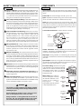
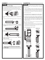
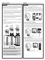
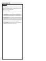
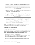
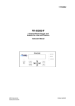
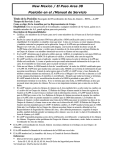
®
Warranty, Service and Repair
To register your product with the manufacturer, fill out the enclosed
warranty card and return it immediately to:
FLOWLINE Inc.
10500 Humbolt Street
Los Alamitos, CA 90720
If for some reason your product must be returned for factory service,
contact your FLOWLINE distributor to receive a material return
authorization number first, providing the following information:
CRICKET™ Alphasonic
Level Transmitter
Model LA12
Owner’s
Manual
1. Part Number, Serial Number
2. Name and telephone number of a person who can answer
questions related to the product and its application.
3. Return shipping address
4. Brief description of the symptom
5. Brief description of the application
Once you have received a material return authorization number, ship
the product prepaid in its original packing to:
FLOWLINE Factory Service
10500 Humbolt Street
Los Alamitos, CA 90720
Please include any related symptom and application information with
your product. This information enables our service technicians to
process your repair order as quickly as possible.
Version 2.2A
©1999 FLOWLINE Inc.
All rights reserved.
Part # LA900001
4/99
WARRANTY
FLOWLINE warrants to the original purchaser of its products that such
products will be free from defects in material and workmanship under
normal use and service for a period which is equal to the shorter of one
year from the date of purchase of such products or two years from the
date of manufacture of such products.
Products which are thought to be defective must be shipped prepaid and
insured to FLOWLINE’s factory or a designated service center (the identity and address of which will be provided upon request) within 30 days
of the discovery of the defect. Such defective products must be accompanied by proof of the date of purchase.
This warranty covers only those components of the products which are
non-moving and not subject to normal wear. Moreover, products which
are modified or altered, and electrical cables which are cut to length
during installation are not covered by this warranty.
THERE ARE NO WARRANTIES WHICH EXTEND BEYOND THE
DESCRIPTION ON THE FACE OF THIS WARRANTY. This warranty
and the obligations and liabilities of FLOWLINE under it are exclusive
and instead of, and the original purchaser hereby waives, all other remedies, warranties, guarantees or liabilities, express or implied. EXCLUDED FROM THIS WARRANTY IS THE IMPLIED WARRANTY
OF FITNESS OF THE PRODUCTS FOR A PARTICULAR PURPOSE
OR USE AND THE IMPLIED WARRANTY OF MERCHANT ABILITY OF THE PRODUCTS.
FLOWLINE’s obligation under this warranty is solely and exclusively
limited to the repair or replacement, at FLOWLINE’s option, of the products (or components thereof) which FLOWLINE’s examination proves
to its satisfaction to be defective. FLOWLINE SHALL HAVE NO OBLIGATION FOR CONSEQUENTIAL DAMAGES TO PERSONAL OR
REAL PROPERTY, OR FOR INJURY TO ANY PERSON.
This warranty does not apply to products which have been subject to
electrical or chemical damage due to improper use, accident, negligence,
abuse or misuse. Abuse shall be assumed when indicated by electrical
damage to relays, reed switches or other components. The warranty does
not apply to products which are damaged during shipment back to
FLOWLINE’s factory or designated service center or are returned without the original casing on the products. Moreover, this warranty becomes
immediately null and void if anyone other than service personnel authorized by FLOWLINE attempts to repair the defective products.
This warranty may not be extended, altered or varied except by a written
instrument signed by a duly-authorized officer of FLOWLINE, Inc.
If FLOWLINE level transmitters or switches are used for process control
where failure of the transmitter or switch could result in personal injury
or property damage, an independent means such as a redundant FLOWLINE point level switch should be used. Where FLOWLINE level transmitters or switches are used as a part of a pressure vessel or pipe, care
should be taken to independently protect against personal injury or property damage should the FLOWLINE sensor fail or be mishandled. Contact FLOWLINE or your local distributor for additional information.
SAFETY PRECAUTIONS
Step Three
Proper Installation and Handling: Because this is an electrically operated device, only properly-trained staff should install and/
or repair this product. Use a proper sealant or gasket with all
transmitter installations. Note: Always install the Viton gasket with
all versions of the LA12-_061. The G threaded version of the Cricket
will not seal unless the gasket is installed properly. Never overtighten the transmitter within the fitting, beyond a maximum of 80
inch-pounds torque. Always check for leaks prior to system start-up.
Wiring and Electrical: A supply voltage of 12-36 VDC is used to
power the LA12 transmitter. The sensor systems should never
exceed a maximum of 36 volts DC. Electrical wiring of the sensor
should be performed in accordance with all applicable national,
state, and local codes.
Material Compatibility: The Cricket™ enclosure (LA12 series)
is made of Polypropylene (PP) with the diaphragm made of Polyethylene (PE). The pipe adapter is made of Polypropylene (PP). The
wave guide can be of either Polypropylene (PP), Polyvinylchloride
(PVC) or Polyvinylidene Fluoride (PVDF). Make sure that the wave
guide which you have selected is chemically compatible with the
application liquids it will contact.
Enclosure: While the transmitter housing is liquid-resistant when
installed properly, it is not designed to be immersed. It should be
mounted in such a way that the enclosure and sensing diaphragm do
not come into contact with fluid.
Flammable, Explosive and Hazardous Applications: The
LA12 transmitter systems should not be used within flammable or
explosive applications.
Make a Fail-Safe System: Design a fail-safe system that accommodates the possibility of transmitter or power failure. In critical
applications, FLOWLINE recommends the use of redundant backup
systems and alarms in addition to the primary system.
WARNING
The Cricket™ is shipped with the pipe adapter installed
in the true union fitting. Remove the pipe adapter before
installing the pipe.
Power LED: This Green LED lights when DC power is On.
Span: Adjustment for the 4mA setting (invert off) or the 20 mA setting
(invert on). Follow instructions in Calibration section, Step 7.
Invert: This switch reverses the logic of the 4-20 mA output. With
Invert Off, 4 mA setting will be at the end of the wave guide and 20 mA
setting will be 2" below the top of the threads. With Invert On, 20 mA
setting will be at the end of the wave guide and 4 mA setting will be 2"
below the top of the threads.
1/2" Conduit Connection: For direct electrical connection.
Power LED
Input
Terminal
SPAN
(-) (+ ) POWER
C
User’s Responsibility for Safety: FLOWLINE manufactures a
wide range of liquid level sensors and technologies. While each of
these sensors is designed to operate in a wide variety of applications,
it is the user’s responsibility to select a sensor model that is appropriate for the application, install it properly, perform tests of the
installed system, and maintain all components. The failure to do so
could result in property damage or serious injury.
Input Terminal: Connect the output device to this terminal. Note the
polarity of the terminal. If polarity is not reversed, the transmitter will not
operate.
GND
About this Manual: PLEASE READ THE ENTIRE MANUAL
PRIOR TO INSTALLING OR USING THIS PRODUCT. This
manual includes information on all models of the Cricket™ Alphasonic continuous contact level transmitter from FLOWLINE: LA12_0_1. Please refer to the part number located on the sensor label to
verify the exact model which you have purchased.
14-36 VD
Step Two
COMPONENTS
4-20 mA
IN V E R
ON
T
OFF
Span
Cricket
™
Alphason
Transm ic
itter
Invert
1/2” Conduit
Connection
Cricket Transmitter: Housing containing the electronics for the
transmitter. The housing is rated NEMA 4X (IP 65) with a material of
construction of Polypropylene (PP), U.L. 94 VO.
Diaphragm: Sensing transducer for transmitting and receiving the
sound pulses. The material of construction for the diaphragm is Polyethylene (PE).
Pipe Adapter: Attaches the wave guide to the transmitter in conjunction with the true union fitting. Material of construction for the pipe
adapter is PP and the female thread is a 1/2" NPT.
True Union Fitting: Attaches the wave guide
to the transmitter. Also provides the mounting
threads for the Cricket™. Threads for the true
union fitting are either 1" NPT or 1" G. Material
of construction for the true union fitting is
Polypropylene (PP).
Wave Guide: Device which directs the sound pulses created by
the transmitter. Materials of construction for wave guides are
Polypropylene
(PP),
Polyvinylidene Fluoride (PVDF)
or Polyvinylchloride (PVC).
Cricket™
Transmitter
(PP)
Diaphragm
(PE)
Pipe
Adapter
(PP)
Avoid installing the Cricket™ near a source of vibrations or loud repetitive noise, such as a motor.
True Union
Tank Fitting
(PP)
Always install the 1" Viton gasket with all versions of
the LA12-_061. The G threaded version of the Cricket
will not seal unless the gasket is installed properly.
Wave Guide
(PP, PVC
or PVDF)
ASSEMBLY
CALIBRATION
Step Four
Step Five
MODEL LA12-_0_1-00" ONLY:
Cricket wave guides may be assembled in the factory or in the field. If
your Cricket was factory assembled, skip to installation. If your Cricket
requires field assembly, then use the following instructions below.
1. First, remove the true union fitting from the transmitter. The assembly can be removed by hand.
The Cricket™ measurement span may be calibrated over the entire
range of the wave guide. Use the following procedure to calibrate the
measurement span.
1. Connect a multimeter in series to read current. The top of the
Cricket's™ current signal is located 2" from the bottom of the threads.
The calibration procedure for the transmitter requires that the bottom
of the transmitter's current signal be set using the Span potentiometer.
2. Set Invert switch to OFF.
3. Set level to lowest point. A cup of liquid or a piece of tape over the end
of the pipe may be used as a substitution for a low level reading.
2. Turn a 1/2" NPT male thread on the end of the 1/2" schedule 40 or 80
pipe.
3. Locate the pipe adapter and thread the pipe into the 1/2" NPT thread.
4. Turn Span until current reads 4 mA. Turning pot counterclockwise
will lower the current and turning the pot clockwise will increase the
current. Always increase current to above 5 mA and slowly return to
4 mA for best results. The Cricket™ is now calibrated for normal
operation. Remove the cup of water or tape and continue on to
Installation (Step Six).
If the Cricket's current signal is need to be reversed (20 mA at the end
of the pipe), continue on to step five.
4. Drill a 1/8" pressure equalization hole through the pipe. The location
of the hole should be placed from 1" to 1-1/2" from the top of the
wave guide.
1" to
1/8" D.
1-1/4"
5. Turn Invert to ON if 20 mA signal at end of LA12 is required. Adjust
pot until 20 mA is read. Always decrease current to below 19 mA and
slowly increase to 20 mA for best results.
6. Remove cup of water or tape if required.
CALIBRATION
5. Make sure all burrs have been removed from the pipe ID.
Power
Supply
4
5
INVERT OFF
6
6. Insert the wave guide assembly into the true union fitting.
mA
com
True Union
Tank Fitting
(+)
Wave Guide Assembly
8. Proceed to the calibration section.
Invert OFF
20 mA
7. Finally, insert the assembled pieces into the transmitter. Tighten the
fitting to hand tight.
4 mA
INVERT ON
Always use a 1/2" schedule 40 or 80 (PP, PVDF
or PVC) pipe.
Invert ON
4 mA
20 mA
INSTALLATION
WIRING
Step Seven
1. Wiring to a FLOWLINE Continuous Controller (LC52):
Connect the (+) terminal to the positive 24 VDC, 4 - 20 mA terminal
on the LC52 controller. Connect the (-) terminal to the GND terminal
on the LC52 continuous controller (See illustration below). Check
LC52 instruction manual for setting the LC52 for loop powered
operation.
GND
14-36 VD
C
INVERT
ON
4-20 mA
Cricket™
Alphas
Transmonic
itter
OFF
R E L AY 1
LATCH
ON OFF
INVERT
PROPORTIONAL
CONTROLLER
0%
R E L AY 2
DELAY
INPUT
RLY2B
POWER
(-) (+ )
RLY2A
P W R
SPAN
2. Unscrew the True Union Tank Fitting from the transmitter. Install
True Union Tank Fitting along with the Wave Guide Assembly into
the fitting. Apply the appropriate amount of sealant to the tapered
threads which will be screwed into the fitting.
RLY1
1. Install the appropriate 1" fitting in the top wall of the tank or stand
pipe. Prior to installation, make sure that the fitting has been installed
properly and checked for leaks. Use a proper sealant at the time of
installation to ensure a liquid-tight seal. Secondly, make sure that the
fitting’s threads are not damaged or worn.
Remove the cap of the LA12 transmitter enclosure. The terminals of the
transmitter are visible from the top of the enclosure.
SPAN
FLOWLINE’s LA12 transmitter may be installed through the tank top,
through a stand pipe top or to the side of a tank. Tank top and stand pipe
installations require a 1" NPT fitting or blind flange. Side wall installations require a side mount bracket from FLOWLINE, model LM501001, and a 2" to 1" NPT reducer bushing or equivalent.
OFF SET
Step Six
100%
INVERT
DELAY
E A S Y CAL
4
20
OP
UP
DOWN
SET
3. Insert the Transmitter on the True Union Tank Fitting and tighten to
hand tight.
4. Always check for leaks prior to system start-up. To ensure proper
installation, a complete leak test and simulation of actual process
conditions should be preformed.
LM50
Side Mount
Bracket
Tank Top
Mounting
Stand Pipe
Mounting
2. Wiring to a Two-Wire Loop Indicator:
The LA12 requires a loop indicator that receives a 4-20 mA current
input. A 12-36 VDC power supply is required for the system. Connect
the (+) terminal of the LA12 transmitter to the positive VDC terminal
on the power supply. Connect the (-) terminal on the LA12 to the (+)
terminal on the loop indicator. Connect the (-) of the loop indicator to
the (-) of the power supply (See illustration below).
DC Power
Supply
SPAN
C
(-) (+ )
INVERT
GND
14-36 VD
12-36 VDC
POWER
ON
OFF
4-20 mA
Cricket™
-
+
-
+
Alphas
Transmonic
itter
SPAN
WARNING
Avoid installing the Cricket™ near a source of vibrations
or loud repetitive noise, such as a motor.
Do not insert or remove the Cricket™ quickly from its
fitting. Doing so may increase the back pressure within
the pipe and cause the diaphragm to rupture.
Always install the 1" Viton gasket with all versions of the
LA12-_061. The G threaded version of the Cricket will not
seal unless the gasket is installed properly.
14-36 VD
GND
C
(-) (+ )
4-20 mA
12-36 VDC
POWER
INVERT
ON
OFF
Cricket™
Alphas
Transmonic
itter
+
-
6
5
4
3
2
1
0
A
250Ω
DC Power
Supply
Typical PLC
3. Wiring to a typical PLC:
The LA12 requires a PLC which provides a 12-36 VDC excitation
and receives a 4-20 mA current input. Connect the (+) terminal of the
LA12 transmitter to the positive VDC power terminal. Connect the
(-) terminal on the LA12 to the (+) channel on the PLC. Connect the
(-) of the PLC to the (-) of the power terminal (See illustration below).
MAINTENANCE
Step Eight
General:
The LA12 series level transmitter itself requires no periodic maintenance except cleaning as required. It is the responsibility of the user to
determine the appropriate maintenance schedule, based on the specific
characteristics of the application liquids.
Cleaning Procedure:
1. Power: Make Sure that all power to the transmitter, controller and/or
power supply is completely disconnected.
2. Sensor Removal: In all through-wall installations, make sure that the
tank is drained well below the sensor prior to removal. Carefully,
remove the sensor from the installation.
3. Cleaning the Sensor: Use a soft bristle brush and mild detergent,
carefully wash the wave guide of the LA12. Do not use harsh
abrasives such as steel wool or sandpaper, which might damage the
transmitter's surface. Do not use incompatible solvents which may
damage the transmitters PP, PVDF or PVC plastic body.
4. Sensor Installation: Follow the appropriate steps of installation as
outlined in the installation section of this manual.
SPECIFICATIONS
Step One
0.3 to 10' (9 cm to 3 m)
± 1% of span in air
0.125” (3 mm)
2 kHz (nominal)
5 per second
0.3' (5 cm) minimum
12-36 VDC
600 ohms @ 36 VDC
4-20 mA, 12-36 VDC
4-20 mA or 20-4 mA
8”
120"
Potentiometer
LED for power status
F: -40º to 140º
C: -40º to 60º
Automatic over range
Atmospheric
Schedule 40 or 80, 1/2"
PVC, PP or PVDF
NEMA 4X / IP65
Polypropylene, U.L. 94 VO
Polyethylene
1” NPT (1" G)
Viton 1" (metric only)
1/2” NPT
PP
EN 50082-2 immunity
EN 55011 emission
Temp. compensation:
Pressure rating:
Wave guide:
Guide materials:
Enclosure rating:
Enclosure material:
Diaphragm material:
Mounting threads:
Mounting gasket:
Conduit connection:
Thread material:
CE compliance:
Ambient Sensor Temperature (°C)
Maximum Temperature/Voltage Derating
Continuous 20 mA Curve
100
Unacceptable
Range
80
60
Acceptable
Range
40
20
0
12
16
20
24
28
32
36
Max. Series Resistance (Ohms)
14-36 V
DC
(- ) (+ )
4-20 mA
POWER
IN V E R
ON
T
OFF
Cricket™
Alphaso
Transm nic
itter
Alphasonic Transmitter
LA12 - _ 0 _ 1
Guide Material
1 - PP
5 - PVDF
7 - PVC
Mounting Thread
0 - 1" NPT
2 - 1" G
Cricket™
Transmitter
(PP)
Diaphragm
(PE)
Pipe
Adapter
(PP)
Flowline Cricket™
Electrical Loading Limits
1,400
1,200
1,000
800
600
400
200
000
12
True Union
Tank Fitting
(PP)
Unacceptable
Range
Wave Guide
(PP, PVC
or PVDF)
Acceptable
Range
18
24
30
36
Supply Volyage (VDC)
(71mm)
Operating Voltage (VDC)
2.8"
About Alphasonic Contact Technology:
An Alphasonic sound wave is pulsed five
times per second from the base of the transducer. The sound wave travels down the pipe
and reflects against the process medium below
before returning back to the receiver. The
electronics measures the time of flight between the sound generation and receipt, and
translates this figure into the distance between
the transmitter and process medium below.
SPAN
GND
Range:
Accuracy:
Resolution:
Frequency:
Pulse rate:
Dead band:
Supply voltage:
Loop resistance:
Signal output:
Signal invert:
Minimum range:
Maximum range:
Span adjustment:
Indication:
Temperature rating:
1.0"
4.2" (106mm)
4.7" (119mm)
5.9" (149mm)
(25mm)
A (Specify)