1
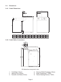
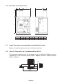
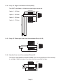
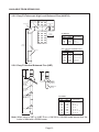
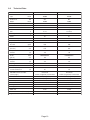
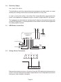
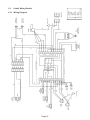
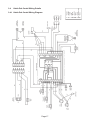
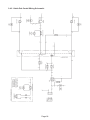
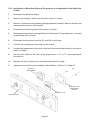
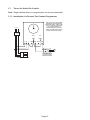
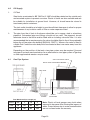
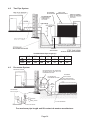
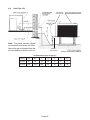
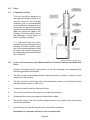
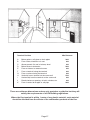
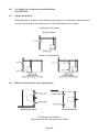
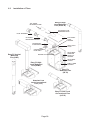
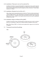
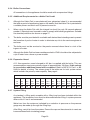
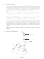
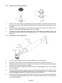
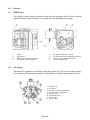
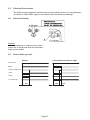
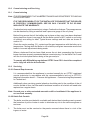
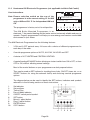
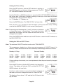
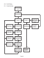
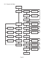
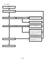
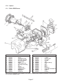
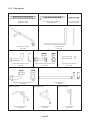
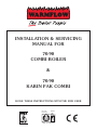
INSTALLATION & SERVICING
MANUAL FOR
70/90
COMBI BOILER
&
70/90
KABIN PAK COMBI
LEAVE THESE INSTRUCTIONS WITH THE END USER
BS 5750
ISO 9002
PART 2
I
ST
FI
REG
RM
BSI
E R ED
NATIONAL
ACCREDITATION
OF CERTIFICATION
BODIES
CERT. No. FM 29884
ISSUE 4
MAR ’03
COMMISSIONING
*THIS APPLIANCE MUST
BE COMMISSIONED
After commissioning ensure that the pre-paid warranty
registration card is filled in and returned.
SERVICING
To ensure continued reliable operation and
fuel economy it is recommended that the
boiler is serviced annually.
Warmflow Engineering Service division
provides an excellent back-up service,
operating a team of Oftec trained engineers
who can meet all the servicing,
commissioning and breakdown
requirements for your appliance.
Simply telephone
TEL: (028) 9262 0852
FAX: (028) 9262 0869
E-MAIL: [email protected]
*Failure to commission this appliance may invalidate warranty
BEFORE FITTING THIS BOILER THE
INSTALLER MUST CHECK:
1.
What the maximum hot water demand is likely to be placed on
the boiler. Not every installation is suitable for a Combi boiler.
Systems requiring very high hot water flow rates may be better
suited with an unvented cylinder.
2.
That the mains are capable of supplying up to 24 litre/min with a
minimum dynamic pressure of 1.8 bar at the boiler. This is to
ensure that the boiler can achieve its maximum output.
3.
The hardness of the mains water supply. Systems with hard water
must be fitted with a suitable chemical scale preventer (eg Fernox
Quantomat or Combimate alternatively contact Warmflow for
further details).
4.
That the flow from any one hot water outlet does not exceed the
maximum recommended. This applies particularly to baths which
are usually fitted with larger taps and larger bore supply pipes. It
may be necessary to restrict the flow to these taps by reducing
the bore of the supply pipework or by fitting a restrictor into the
pipework.
5.
That any outlet when opened does not starve all the other outlets
of hot water. If more than one outlet is open at the same time
then the total flow from all the outlets should not exceed the
maximum flow rate of the boiler.
6.
That any showers being supplied hot water by the boiler are
compatible with this type of appliance.
It should be noted that the boiler has been factory fitted with
an 18 litre/min flow restrictor.
The manufacturers guarantees are void if the appliance is
not installed and commissioned in accordance with the
recommendations made herein.
Page 1
Contents
Page
1.0
User Instructions ................................................................................................................. 3
1.1
Introduction ................................................................................................................. 4
1.2
General Requirements ................................................................................................ 4
1.3
Components................................................................................................................ 5
2.0
Technical Details .................................................................................................................. 7
2.1
Sequence of Operation Flow Chart............................................................................. 7
2.2
Baffles ......................................................................................................................... 8
2.3
General Requirements ................................................................................................ 8
2.4
Dimensions ................................................................................................................. 9
2.5
Combi Flue Options .................................................................................................. 10
2.6
Technical Data .......................................................................................................... 13
3.0
Electricity Supply ............................................................................................................... 14
3.1
RDB Burner Control Box ........................................................................................... 14
3.2
Fitting a Room Thermostat ....................................................................................... 14
3.3
Combi Wiring Details ................................................................................................ 15
3.4
Kabin Pak Combi Wiring Details ............................................................................... 17
3.5
Frost Thermostats ..................................................................................................... 19
3.6
Timers for Standard Combi ....................................................................................... 20
3.7
Timers for Kabin Pak Combis ................................................................................... 22
4.0
Oil Supply ........................................................................................................................... 23
4.1
One Pipe System ...................................................................................................... 23
4.2
Two Pipe System ...................................................................................................... 24
4.3
De-aerator System .................................................................................................... 24
4.4
One Pipe Lift ............................................................................................................. 25
5.0
Flues .................................................................................................................................. 26
5.1
Conventional Flues ................................................................................................... 26
5.2
Low Level Discharge/Low Level Balanced Flues Terminal Position ......................... 26
6.0
Air Supply for Combustion and Ventilation ..................................................................... 28
6.1
Open Flue Boilers ..................................................................................................... 28
6.2
Balanced Flue Boilers ............................................................................................... 28
6.3
Installation of Flues ................................................................................................... 29
7.0
Thermostat Control Knob Peg Setting ............................................................................. 31
8.0
Installation .......................................................................................................................... 32
8.1
Hearth ....................................................................................................................... 32
8.2
Service Access.......................................................................................................... 32
8.3
Heating System......................................................................................................... 32
8.4
Domestic Hot Water .................................................................................................. 34
8.5
Removal of Flow Restrictor ....................................................................................... 34
8.6
Fitting a Vertical Flue Adaptor ................................................................................... 35
8.7
Installation of Air Intake Duct .................................................................................... 35
9.0
Burners ............................................................................................................................... 36
9.1
RDB Burner............................................................................................................... 36
9.2
Oil Supply.................................................................................................................. 36
9.3
Electrical Connections .............................................................................................. 37
9.4
Electrode Setting....................................................................................................... 37
9.5
Burner Start-up Cycle ............................................................................................... 37
10.0 Commissioning and Servicing ......................................................................................... 38
10.1 Commissioning ......................................................................................................... 38
10.2 Servicing ................................................................................................................... 38
11.0 Horstmann 626 Electronic Programmer .......................................................................... 39
12.0 Fault Finding ...................................................................................................................... 44
12.1 Central Heating ......................................................................................................... 44
12.2 Domestic Hot Water .................................................................................................. 45
12.3 Burner ....................................................................................................................... 46
13.0 Spares ................................................................................................................................. 47
13.1 Riello RDB Burner..................................................................................................... 47
13.2 Pipe Spares .............................................................................................................. 48
13.3 Short Parts List ......................................................................................................... 49
Page 2
1.0 User Instructions
1.0.1 Boiler Control Thermostat
The boiler control thermostat is located on the front of the boiler facia panel and may
be adjusted from 52°C to 85°C. The recommended minimum thermostat setting is
65°C. Below this ‘cold water corrosion’ is likely to occur thus reducing the life of the
heat exchanger and is not covered by the manufacturer’s warranty. When using hot
water only it is recommended that the boiler control thermostat is switched to the off
position.
1.0.2 Mains Indicator
The green mains light will be lit when there is power to the control panel.
1.0.3 H/L Reset
The yellow H/L reset lamp will be lit when the high limit thermostat has tripped at its set
temperature of 110°C. This cuts off power to the burner and may indicate that there is
a fault in the heating system. The high limit thermostat has a manual reset button
located underneath the control panel in line with the control thermostat. Once the
temperature has fallen and the reset button has been pressed the boiler should restart.
If the high limit thermostat continues to trip contact your service engineer/technician.
1.0.4 Lock Out
The red lock out lamp will be lit when the burner has failed and can be reset by pressing
the illuminated red reset button on the burner control box. If there is power and the
thermostat is calling for heat and the burner has been reset it will go through its start
up cycle. If the burner again fails to fire this would indicate a burner fault or oil supply
problem (oil supply problems are not covered by manufacturers warranty).
1.0.5 Tank Control Thermostat
Located on the right hand side of the control panel the tank control thermostat controls
the temperature in the thermal store. The temperature is adjustable up to a maximum
of 80°C. A peg has been fitted to the rear of the knob to prevent the temperature being
set too high. To change the setting see page 31.
1.0.6 Tank Limit Thermostat
Located inside the control panel the tank limit thermostat is a thermal resetting device
controlling the on/off operation of the burner in hot water mode.
1.0.7 Hot Water and Central Heating On/Off Switch
Both hot water and central heating operations can be controlled via these switches.
However it should be noted that when both switches are in the ‘on’ position hot water
will have priority. In addition whenever a timer or programmer is connected to the
boiler one or more of these switches may be bypassed.
1.0.8 Pressure Gauge
The pressure gauge fitted to the front of the control panel measures system pressure.
The pressure should be set at 1 bar when the boiler is cold. As the boiler heats up, the
pressure will rise but should not exceed 3 bar.
1.0.9 Servicing
It is recommended that the boiler is serviced annually by an OFTEC registered engineer.
Page 3
1.1
Introduction
Note: All our domestic appliances have been independently tested and accredited
as exceeding the minimum SEDBUK efficiency levels required for its type, in
compliance with the Building Regulations Approved Document L1 2001 for
England and Wales and the Building Standards (Scotland) Regulations 2001
Part J.
The Warmflow oil fired ‘Combi’ boiler and Kabin Pak Combi are suitable for sealed
central heating systems and can provide at mains pressure domestic hot water without
the use of a cylinder.
The Warmflow oil fired combis are designed to burn Class C2 (28 sec redwood) kerosine
or Class D (35 sec redwood) gas oil. However to comply with building regulations only
kerosine may be burned when using the low level balanced flue or low level conventional
flue.
As standard the appliance is fitted with a system expansion vessel, circulating pumps,
filling loop, pressure gauge and safety valve. An optional 7-day electronic programmer
is also available.
The pressure jet oil burner is covered by the manufacturer’s parts and labour warranty
valid for one year (from the boiler date stamp). The boiler and heat store are covered
by a manufacturer’s warranty of 5 years (from the boiler date stamp) but does not
include burner, labour, handling or shipping. Details of any extended warranties are
contained within the installation pack.
Optional extended guarantees, for the appliance covering parts and labour of up to 5
years initially are also available (although not applicable to the Republic of Ireland).
The manufacturer’s guarantees are void if the appliance is not installed and
commissioned in accordance with the recommendations made herein.
1.2
General Requirements
The installation of the boiler must be in accordance with the following regulations.
BS5410 : PART 1 : 1997 Code of practice for oil firing.
BS5449 : PART 1 : 1997 Forced circulation hot water systems.
BS7593 : 1992 Treatment of water in domestic hot water central heating systems.
Current Building Regulations: Part J England and Wales
Part F Scotland
Part L Northern Ireland
Current IEE Regulations:
BS7074 : PART 1 : Application Selection & Installation of Expansion Vessels
The heating system should be installed by a competent installer in accordance with
the recommendations laid down by HVCA, OFTEC and a sound engineering practice.
In order to comply with GB building regulations OFTEC forms CD10 for
installations and CD11 for commissioning should be left with the customer.
Page 4
1.3
Components
1.3.1 Combi Assembly
8
9
1
10
11
12
2
13
14
3
4
15
5
16
17
6
18
7
1.
2.
3.
4.
5.
6.
7.
8.
9.
Automatic Air Vents
Boiler Heat Exchanger
Boiler Control and Limit Stat
12 Litre Esxpansion vessel
Boiler Data Plate
RDB Burner
Boiler Drain Valve
Pressure Relief Valve
Strainer
10.
11.
12.
13.
14.
15.
16.
17.
18.
Filling Loop
Tank Control and Limit Stat
Flow Switch
Mixer Valve
Plate Heat Exchanger
CH Pump Head
DHW Pump Head
Pump Gate Valves (x3)
Tank Drain Valve
1.3.2 Combi Control Panel
BOILER
CONTROL
THERMOSTAT
CH
PUMP
MAINS ON
LAMP (GREEN)
HIGH LIMIT TRIPPED
LAMP (YELLOW)
TANK CONTROL
THERMOSTAT
BLANKING
PLATE
BURNER LOCKOUT
LAMP (RED)
DHW
PUMP
HIGH LIMIT THERMOSTAT
RESET (UNDERNEATH)
Page 5
CH ON/OFF
SWITCH
SYSTEM
PRESSURE
GAUGE
1.3.3 Kabin Combi Assembly
1
2
3
4
5
6
24
7
23
8
22
21
9
20
19
10
11
1.
2.
3.
4.
5.
6.
7.
8.
Flue Terminal Guard
Low Level Flue
Service Access Hatch
Control Panel Cover
Controls
Pressure Vessel
Control Panel Flap Lock
Control Panel Flap
9.
10.
11.
12.
13.
14.
15.
16.
12
13
14
16
15
17
Door Panel
Burner Reset
Burner Reset Button
Burner
Return Connection
DHW Pump
CH Pump
Cable on Oil Line Grommets
18
17.
18.
19.
20.
21.
22.
23.
24.
Air Intake Grill
Pipe Access Hole
Plate Heat Exchanger
Mixing Valve
Side Panel
Pipe Entry Grommets
Auto Air Vent
Pressure Relief Valve
Note: To convert the Kabin Pak for use with a conventional flue use the Kabin Pak adaptor
(KPA).
1.3.4 Kabin Pak Combi Control Panel
High Limit
Thermostat Reset
Mains On (Green)
Tank Control
System
Thermostat Pressure Gauge
CH Pump
High Limit (Yellow)
Burner Lockout (Red)
DHW Pump
Boiler Control
Thermostat
DHW ON/OFF
Switch
Page 6
CH ON/OFF
Switch
2.0
Technical Details
2.1
Sequence of Operation Flow Chart
NO
Power
On
NO
YES
Timer
Calling For
Heat
YES
NO
HW
Selected
YES
Flow
Switch
Closed
YES
NO
YES
DHW
Tank Stat
Satisfied
NO
HW
Limit Stat
Tripped
CH
Selected
NO
YES
Boiler
Limit Stat
Tripped
NO
Boiler
Stat
Satisfied
NO
Press
Reset
Button
YES
Boiler
Limit Stat
Tripped
NO
YES
Burner
Fires
Burner
Stops
YES
Press
Reset
Button
NO
CH Pump
Only Runs
YES
YES
NO
Room
Stat
Satisfied
YES
DHW
Pump Only
Runs
Burner
Fires
The boiler will have a DHW priority when both domestic hot
water (DHW) and central heating (CH) are selected. So if
the flow switch is closed or the heat store has not been
satisfied the entire output of the boiler is directed to DHW
before the boiler will switch over to CH. When fully cold it
can take up to 20 minutes for the heat store to be satisfied.
After a draw-off of 120L at 24L/min, with an average
temperature rise of 32°C, the thermal store has a recovery
time of approximately 7 mins.
Note: If HW has not been selected no hot water can be
produced even if the heat store is up to temperature.
Page 7
2.2
Baffles
FRONT
Before firing make sure the baffles have not been dislodged in transit and are correctly
positioned. To achieve maximum efficiency push the baffles in the direction of the
arrows as shown.
2.3
General Requirements
1.
The Warmflow Combi is supplied with all the necessary components for a sealed heating
system. However, on some larger systems with a total water content greater than
approx 150L, an expansion vessel, in addition to the integral 12L vessel supplied, may
be required.
2.
The pressure relief discharge shall be positioned away from any electrical components.
No other valves should be positioned between the relief valve and the discharge, and
the discharge pipe should not be used for any other purposes. The discharge pipe
must be plumbed to an external drain in a position where the discharge can been seen
but cannot cause any injury or damage.
3.
Where there is a catastrophic loss of water from the system the boiler thermostats
may fail to operate which would result in serious damage to the appliance. To prevent
this it is recommended that a low pressure cut out switch set at 0.2 bar is fitted to the
system and wired in series with the boiler limit thermostat.
4.
The boiler should be stored in a dry environment. No heavy objects should be placed
on top of the boiler. Where possible the boiler should be moved on its pallet or trucked
from its rear. Manhandling the boiler by its casings will result in damage and must be
avoided.
Page 8
2.4
Dimensions
2.4.1 Combi Dimensions
B
K
J
L
C
H
A
G
F
D
E
MODEL
A
B
C
D
E
F
G
H
J
K
L
70/90
865
595
595
90
59
554
750
125
127
127
203
2.4.2 Combi Boiler Connections
1620
1310
820
460
1 2
3 4
8130
8000
8045
5
6
REAR VIEW
All dimensions are given in mm.
1.
2.
3.
Cold Mains (15mm)
Heating Flow (22mm)
Domestic Hot Water (22mm)
4.
5.
6.
Page 9
Pressure Relief Discharge (15mm)
Spare Connection (1” BSP)
Central Heating Return (1” BSP)
2.4.3 Kabin Pak Combi Dimensions
H
E
J
G
F
D
A
B
2.5
C
MODEL
A
B
C
D
E
F
G
H
J
70/90
892
732
636
373
188
191
376
172
371
Combi Flue Options (not applicable to the Kabin Pak Combi)
Note: Low level flue options are rear or left hand outlet only.
2.5.1 ‘Easy Fit’ Telescopic Low Level Balanced Flue (BF-R)
The horizontal dimension can be increased up to an additional 1200mm using a
combination of long extension pieces (E600 = 600mm) and short extension pieces
(E300 = 300mm).
102
Ø125
225 MAX
175 MIN
712 MAX
490 MIN
Page 10
2.5.2 ‘Easy Fit’ High Level Balanced Flue (HLBF)
The HLBF is available in 4 fixed horizontal lengths which are:
SEE OPTIONS
Option 1 – 455mm
160x160
Option 2 – 655mm
Option 3 – 585mm
Option 4 – 785mm
1128
225 MAX
175 MIN
2.5.3 ‘Easy Fit’ Telescopic Low Level Conventional Flue (LLF-R)
102
Ø125
155 MIN
225 MAX
792 MAX
540 MIN
2.5.4 Standard Low Level Conventional Flue (LLF)
The factory supplied elbow may be extended up to 1m horizontally and 1.5m vertically
by welding on additional pipe or by using vitreous enamelled flue pipe.
102
155x155
155 MIN
225 MAX
575
Page 11
AVAILABLE FROM SPRING 2003
2.5.5 Easy Fit Telescopic High Level Balanced Flue (HLBF-R)
A
EXTENSION KITS
AS REQUIRED
(PACKS C OR D)
PACK E OR F
PACK E OR F
175 MIN
225 MAX
ALL MODELS
DIM A
FLUE PACKS
MIN
MAX
435
610
A+E
560
860
A+F
735
910
A+C+E
1570 MIN
2070 MAX
50/70, 70/90 & 90/120 MODELS ONLY
PACK A
DIM A
FLUE PACKS
MIN
MAX
860
1160
A+C+F
1035
1210
A+C+C+E
1160
1510
A+C+C+F
1385
1560
A+D+E
1510
1860
A+D+F
2.5.6 Easy Fit Vertical Balanced Flue (VBF)
675mm
MIN
675mm
MIN
PACK H
PITCHED ROOF
FLASHING
(22" – 45"
ADJUSTABLE)
PACK G
FLAT ROOF
FLASHING
PACK B
VBF TERMINAL
SECTION
PACK B
VBF TERMINAL
SECTION
EXTENSION KITS
(PACK C OR D) AS
REQUIRED
MAX 2 NO PACK D
ALL MODELS
FLUE HEIGHT
PACK A
FLUE PACKS
MIN
MAX
1340
1840
A+B
1640
2140
A+B+C
1940
2440
A+B+C+C
2290
2740
A+B+D
2590
3040
A+B+D+C
2890
3340
A+B+D+C+C
3240
3740
A+B+D+D
Note: When using a VBF or HLBF-R on a 120/150 or 150/200 model ensure that the
boiler is fitted with a RDB3 burner.
Page 12
2.6
Technical Data
70/90 Combi
Model
Nominal heat
Input
Nominal heat
Output
Efficiency at max output (net)
KW
Btu/hr
KW
Btu/hr
%
Burner
Head
Flue
mm
70/90 Kabin Pak Combi
29.3
29.3
100,000
100,000
26.4
26.4
90,000
90,000
90
90
RDB 1
RDB 1
LD3
LD3
100 or 127
Integral
Size
in
4 or 5
Low Level
Max CO2
%
11.5-12.0
11.5-12.0
0-1
0-1
°C
235
235
mbar
12.0
12.0
l/h
3.15
3.15
Flow rate
gals/h
0.69
0.69
Nozzle
make
DANFOSS 60°S
DANFOSS 60°S
(kerosine)
size
0.75
0.75
Pump
bar
8
8
Pressure
psi
116
116
Smoke
FGT at max output
Water resistance at 20°C ∆T
Approx fuel
Nozzle
make
DANFOSS 60°S
DANFOSS 60°S
(gas oil)
size
0.6
0.6
Pump
bar
12
12
Pressure
psi
175
175
Dry weight
kg
155
155
L
70
70
Min inlet dynamic pressure
bar
1.8
1.8
for max hot water flow
psi
Primary water content
Max DHW flow rate achievable
(refer to page 1)
Factory set DHW flow rate
Min DHW flow rate
DHW temp rise
°C
Pressure Relief
26
26
Unrestricted
Unrestricted
24 l/min (5.3 gals/min) recommended
24 l/min (5.3 gals/min) recommended
18 l/min (4.0 gals/min)
18 l/min (4.0 gals/min)
2.5 l/min (0.55 gals/min)
2.5 l/min (0.55 gals/min)
32°C @ 24 L/min for 120L draw off
32°C @ 24 L/min for 120L draw off
3 bar (43.5 psi)
3 bar (43.5 psi)
Heating flow
22 mm
22 mm
Heating return
1” BSP
22 mm Comp.
DHW outlet
Cold water mains inlet (refer to page 1)
Ingress Protection
22 mm
22 mm
Unrestricted 15 mm bore (minimum)
Unrestricted 15 mm bore (minimum)
IPX0
IP45
Page 13
3.0
Electricity Supply
220 - 240V. 1PH, 50 Hz
The boiler/burner and other external electrical equipment should be wired via a fused
double pole isolating switch which should be fitted with a 5 amp fuse.
In order to ensure the safety of the Kabin Pak Combi Warmflow recommends that
power to the appliance is supplied through a suitable CE approved RCD trip switch.
The appliance must be effectively earthed and all external wiring should comply with
current IEE Regulations. It is the responsibility of the installer to ensure that the appliance
has been properly earthed.
Earth
Neutral
Live
RDB Burner Control Box
Lock Out
3.1
CONTROL BOX
535SE/LD
Fan
Housing
M
Photoresistance
Motor
Black
White
Blue
Oil Valve
M
Capacitor
3.2
Fitting a Room Thermostat
PCB
26
27
28
29
30
N
5
ROOM THERMOSTAT
Remove the purple wire from no 5 and no 28 on the PCB and wire the thermostat as
shown. The room thermostat should be located where it is not subjected to extraneous
heat gains, direct sunlight or draughts.
Page 14
P
O
Y
R
W
BR
BL
B
G/Y
3.3
3.3.1 Wiring Diagram
– Purple
– Orange
– Yellow
– Red
– White
– Brown
– Blue
– Black
– Green/Yellow
Combi Wiring Details
Page 15
BREAK INTO THE WHITE
WIRE BETWEEN NO 16 ON
THE PCB AND THE LIMIT
STAT AND CONNECT IN THE
PRESSURE SWITCH WITH A
WIRING BLOCK AS SHOWN
3.3.2 Combi Wiring Schematic
Page 16
P
O
Y
R
W
BR
BL
B
G/Y
GY
3.4
3.4.1 Kabin Pak Combi Wiring Diagram
Page 17
– Purple
– Orange
– Yellow
– Red
– White
– Brown
– Blue
– Black
– Green/Yellow
– Grey
Kabin Pak Combi Wiring Details
BREAK INTO THE WHITE
WIRE BETWEEN NO 16 ON
THE PCB AND THE LIMIT
STAT AND CONNECT IN THE
PRESSURE SWITCH WITH A
WIRING BLOCK AS SHOWN
3.4.2 Kabin Pak Combi Wiring Schematic
Page 18
3.5
Frost Thermostats
3.5.1 Combi Boilers
The switched live from the frost thermostat (the frost thermostat must be supplied by a
permanent live) should be connected to number 5 on the boiler terminal block. In order
to protect the fabric of the building as well as the boiler and pipework, the thermostat
should be located in the coldest part of the house but where it can respond to any
temperature rise.
FROST THERMOSTAT
PERMANENT
LIVE
3
4
5
6
3.5.2 Kabin Pak Combi Boilers
As the boiler is supplied with a factory fitted frost thermostat all that is required is for a
permanent live to be supplied to the control panel.
Page 19
3.6
Timers for Standard Combi
Note: Single channel timers or programmers are not recommended.
3.6.1 Installation of a remote two channel programmer (option 1)
Remove the purple wire connecting 5
and 28 and the white wire connecting 3
and 19.
Connect the programmer as shown via
a fused isolator.
E
This bypasses the central heating and
hot water on/off switch.
N
L
CH
HW
COM
COM
OFF
ON
OFF
ON
12
11
If the connection to terminal 12 is not
made the mains on lamp is also
bypassed.
EARTH
POST
28
27
26
25
A separate live supply to the boiler is
not required. However a neutral and
earth must be supplied to the boiler.
24
22
23
21
20
19
PCB CONTROLLER
3.6.2 Installation of a remote two channel programmer (option 2)
Remove the purple, white and brown wires
connecting the central heating and hot water
on/off switches to the 6 pin male plug.
Connect the programmer as shown.
The mains is supplied via a fused isolator
to the boiler 3 pin mains plug.
E
N
L
CH
HW
COM
COM
OFF
ON
OFF
ON
1
2
3
4
5
6
EARTH
POST
Page 20
3.6.3 Installation of Warmflow Optional Programmer (not applicable to the Kabin Pak
Combi)
1.
Disconnect the electrical supply.
2.
Remove top casing (4 studs) and control box cover (1 screw).
3.
Remove 2 screws securing blanking plate/programmer bracket. Remove bracket and
blanking plate from the control panel.
4.
Disconnect the blanking plate from bracket (2 screws).
5.
Feed programmer harness through the hole in the bracket. The programmer is secured
to the bracket with 2 screws.
6.
Disconnect the 6 pin plug from the CH and HW on/off plugs.
7.
Connect the programmer 6 pin plug into the socket.
8.
Locate the programmer into the hole in the facia and secure the bracket to the control
panel (2 screws).
9.
Set the time switch on the rear of the programmer to ‘G’ or ‘P’ (see programmer
instructions).
10.
Replace the control panel cover and reconnect electrical supply.
11.
Operational instructions are included in this handbook. (Section 11, Page 27)
OPITIONAL
PROGRAMMER
BLANKING PLATE/
PROGRAMMER
BRACKET
BLANKING PLATE
CONTROL PANEL
Page 21
3.7
Timers for Kabin Pak Combis
Note: Single channel timers or programmers are not recommended.
3.7.1 Installation of a Remote Two Channel Programmer
THE HW AND CH SELECTOR
SWITCHES ON THE BOILER
CONTROL PANEL SHOULD BE
LEFT IN THE OFF POSITION
BUT CAN BE USED AS
SERVICING SWITCHES TO
TURN THE BOILER ON EVEN
WHEN THE CLOCK IS OFF
L N E
R C D
E N L
HW
CH
COM
COM
OFF
ON
OFF
ON
5
3
ISOLATOR TO BE
FITTED WITHIN
BOILER CASING
BOILER MAINS PLUG
Page 22
4.0
Oil Supply
1.
Oil Tank
Steel tanks constructed to BS 799 Part 5 1987 should be painted on the outside only
and mounted on piers to prevent corrosion. Plastic oil tanks are also available and can
be suitable for installation at ground level. However, oil should never be stored in
translucent plastic containers.
The tank outlet should be at a height to provide sufficient clearance to allow for proper
maintenance of any isolation valve oil filter or water separator fitted.
2.
The pipe from the oil tank to the burner should be run in copper, steel or aluminium
pipework. Galvanised pipe and fittings should not be used. The pipework should
terminate close to the boiler and be fitted with an isolating valve and filter. It is also
recommended that a remote sensing fire valve should be fitted to the oil line preferably
before the oil line enters the building (BS5410 : PART 1). Where a fire valve is fitted to
a Kabin Pak Combi the valve body must be situated at least one metre away from this
appliance.
Depending on the position of the tank a two pipe system may be required. One and
two pipe oil systems are shown below. As an alternative to a two pipe system a Tigerloop
or other approved de-aerator. may be used.
4.1
One Pipe System
20mm PER METRE SLOPE
WATER
SEPARATOR
Total Maximum Pipe Length (m)
Head H(m)
0.5
1
1.5
2
I.D.
8 mm
I.D.
10 mm
10
20
40
60
20
40
80
100
Note: Plastic oil level gauges may shrink when
exposed to kerosene thus allowing the ingress of
water. Pump failures due to water contamination
are not covered under the warranty.
Page 23
4.2
Two Pipe System
APPROVED
SITE GAUGE
20mm PER
METRE SLOPE
WATER
SEPARATOR
Total Maximum Pipe Length (m)
4.3
Lift H(m)
0.5
I.D.
8 mm
I.D.
10 mm
35
100
1
1.5
2
30
25
20
15
8
6
100
100
90
70
30
20
0.5
3
3.5
De-aerator System
FIRE VALVE SENSOR
DE-AERATOR MAY BE ABOVE OR
BELOW BURNER AND MUST BE
POSITIONED OUTSIDE
FILTER MAY BE
POSITIONED OUTSIDE
APPROVED
SITE GAUGE
PLASTIC TANK SHOWN
STEEL TANK ALSO SUITABLE
NONRETURN
VALVE
FIRE VALVE
DE-AERATOR
Must be upright
FILTER
‘T’ & TAP FOR DRAIN
SHUT OFF VALVE
For maximum pipe length and lift contact de-aerator manufacturer.
Page 24
4.4
One Pipe Lift
APPROVED
SITE GAUGE
Note: The pump vacuum should
not exceed a maximum of 0.4 bar.
Above this gas is released from the
oil thus leading to burner lock out.
20mm PER METRE SLOPE
WATER
SEPARATOR
Total Maximum Pipe Length (m)
Lift H(m)
0.5
0.5
1
1.5
2
3
3.5
ID 8mm
35
30
25
20
15
8
6
ID 10mm
100
100
100
90
70
30
20
Page 25
5.0
Flues
5.1
Conventional Flues
The flue should be designed in
accordance with the local bye-laws
and the Clean Air Act. Draught
stabilisers are not recommended
for oil fired boilers. Sharp bends or
horizontal runs should be avoided
and the flue should terminate 2 feet
(600 mm) above the ridge of the
dwelling. Terminals which restrict
the discharge or allow ingress of
water should be avoided.
It is recommenced that when
connecting to an existing masonry
chimney a flexible stainless steel
liner of the correct diameter should
be used. The annular space must
be sealed top and bottom and filled
with insulation.
5.2
Low Level Convert/Low Level Balanced Flues Terminal Positions and Kabin Pak
Flues
Attention should be given to the position of the flue discharge; we recommend the
following guidelines be adopted.
1.
The flue should not discharge beneath opening windows or within 2 metres of other
accesses to the building.
2.
The flue should not discharge near internal/external corners of the building where
turbulent wind conditions could occur.
3.
A terminal guard should be fitted at all times.
4.
The terminal should not discharge over property boundaries.
5.
Discharge into narrow passageways should be avoided.
6.
The actual siting of the flue should be determined by the installer after consultation
with the householder.
7.
In positioning this flue the wind direction should be considered.
Installation in exposed positions is not recommended.
Page 26
Terminal Position
A
B
C
D
E
F
G
H
I
J
K
Min Distance
Below gutters, soil pipes or drain pipes
From a door, window or air vent
Above ground, flat roof or balcony level
Below eaves or balconies
From an internal or external corner
From a terminal facing the terminal
From a surface facing the terminal
Vertically from a terminal on the same wall
Horizontally from the terminal on the same wall
Directly below an opening, air brick, window, etc.
From a vertical drain pipe or soil pipe
1000
600
600
1000
600
600
600
1500
600
600
1000
These are minimum dimensions and are only quoted as a guideline but they will
satisfy the requirements of all UK Building regulations.
Where the flue terminal is within 1 metre of any plastic material, such material
should be shielded from the effects of the combustion products of the flue.
Page 27
6.0
Air Supply for Combustion and Ventilation
(see BS 5410)
6.1
Open Flue Boilers
When the boiler is sited in a cellar where the only access for combustion and ventilation
air is at high level then the combustion air should be ducted to low level.
Combustion Air Supply
Boiler in Room
Boiler in Compartment
6.2
Balanced Flue Boilers in a Compartment
Air Supply for Ventilation
No Combustion Air Inlet required to Room
Page 28
6.3
Installation of Flues
TOP PANEL
BLANKING PLATE
Easy Fit High
Level Balanced
Flue (HLBF-R)
OPTIONAL FLUE
DRESSING RING
FLUE TERMINAL
TOP PANEL
OPTIONAL
EXTENSION PIECES
FLUE
GASKET
HORIZONTAL
FLUE ADAPTOR
TEST HOLE
PLUG
CONVENTIONAL
FLUE RING
Easy Fit Vertical
Balanced
Flue (VBF)
BOILER LID
AIR INTAKE
ADAPTER
SPIGOT &
GASKET
AIR INTAKE
COVER
Easy Fit High
Level Balanced
Flue (HLBF)
RIELLO RDB
BURNER
Easy Fit
Balanced Flue
(BF-R)
Standard Low
Level Conventional
Flue (LLF)
Easy Fit Low Level
Conventional Flue
(LLF-R)
Page 29
6.3.1 Installation of a Balanced Flue (BF-R, HLBF-R & VBF)
1.
Make a suitable sized hole in the wall or ceiling for the flue kit. Add the dimensions
given on pages 6 (Dimension G) and 8 (Flue Vertical Dimension). The cavities around
the opening must be sealed and protected by a non-combustable sleeve.
2.
Remove the top panel (kitchen and utility models) and the combustion chamber lid.
3.
Remove the flue ring from the top of the boiler (3 screws) ensuring that any remaining
silicone sealant has been cleaned away.
4.
Carefully fit the inner and out seals to the flue adaptor.
Note: After fitting the seals to the flue smear them with soap or any suitable lubricant
which does not react with the silicone rubber.
5.
Place the gasket correctly on the boiler and locate the flue adaptor over this, fixing it in
position using the nuts and bolts provided. For BF-R side outlet options on white case
boilers it will be necessary to manoeuvre the adaptor through the side panel before
fixing it to the boiler after the blanking plate has been removed. Push boiler into position
against the wall.
6.
If fitting extension pieces ensure the seals are correctly fitted and lubricated before
pushing through the wall and attaching to the flue adaptor.
Note: Any combination of short (300mm) and long (600mm) extension pieces for the
BF-R can be used up to a maximum additional length of 1200mm.
7.
Slide the flue terminal into position with a twisting movement ensuring that it protrudes
through the wall by a minimum of 175mm and a maximum of 225mm or through the
roof by a minimum of 665mm.
8.
Seal the gap between the flue and the wall both inside and out after which the protective
basket must be fitted to the wall over the flue terminal.
9.
After removing the air inlet cover fit the air intake adaptor spigot and gasket to the
burner. Connect one end of the air duct to the flue and the other end to the air intake
spigot on the burner. Both ends should be securely fastened with the jubilee clips.
10.
The boiler is now ready to be connected to the plumbing, oil supply and mains electricity.
11.
The baseplate of the Goldbird and Whitebird has been designed to allow the oil pipe
and electric cable to pass unnoticed inside the unit from the rear of the installation.
Alternatively the grommeted holes either side, towards the front of the baseplate, can
be used.
12.
A test hole for commissioning purposes has been provided on the boiler lid.
Page 30
6.3.2 Installation of Telescopic Low Level Conventional Flue
Installation instructions as per the balanced flue except there is only an inner seal, the
burner does not require modification and there is no flexible hose to be fitted. In addition
the low level flue should only protrude through the wall by a minimum of 155mm and a
maximum of 225mm.
6.3.3 Installation of Standard Low Level Flue (LLF)
After cutting a hole in the wall place the flue in the hole. The flue must be a minimum of
155mm through the wall. Fit the steel elbow into the pressed ring on the boiler and the
end of the flue kit. The elbow should then be sealed into both rings using high
temperature silicone sealant or fire cement which may also be used in conjunction
with glass fibre rope.
6.3.4 Installation of High Level Balanced Flue (HLBF)
Installation instructions as per the balanced flue except there are no seals involved as
the flue is not telescopic. There are no extension pieces available for these units.
Note: When filling a HLBF to a Combi a new top panel with a larger cut out for the flue
is required.
7.0
Thermostat Control Knob Peg Setting
Tank
INCREASE
TEMPERATURE
SETTING
DECREASE
TEMPERATURE
SETTING
REAR VIEW
Page 31
8.0
Installation
The boiler installation must be in compliance with BS 5410 Part 1 1997 and the Building
Regulations.
8.1
Hearth
The boiler hearth temperature is between 50OC and 85OC and should be stood on a
rigid, non-porous, non-combustible base, which is not softened by warmth to comply
with the Building Regulations.
8.2
Service Access
8.2.1 Combi
24" (600 mm) Clearance should be provided above and in front of the boiler to allow
for routine servicing. If placed under a worktop ensure that the worktop is easily removed.
8.2.2 Kabin Pak Combi
The Kabin Pak Combi has been designed to allow fitting into a corner. However a
minimum clearance of 600mm should be provided to the front and right hand side of
the Kabin Pak to allow access for servicing.
8.3
Heating System
The heating system should be installed to HVCA current codes of practice.
Before installing the boiler the new or existing system should be thoroughly flushed to
clear all sludge or other foreign matter such as solder, steel wool and copper fillings.
We recommend that the system is cleaned out in accordance with BS 5449 and BS
7593:1992 using a suitable non-corrosive commission cleanser.
It is further recommended that a suitable corrosion inhibitor is added to the heating
system, which will not damage the synthetic rubber membrane of the expansion vessel.
8.3.1 Air Vents
An automatic air vent complete with is own check valve is fitted to the top of the heat
store and boiler heat exchanger. However it is recommended that another air vent is
fitted at the highest point in the system.
8.3.2 Drain Cock
Drain cock(s) should be fitted to the lowest points in the system to enable the system
to be fully drained. A drain cock has also been fitted to the heat store and boiler heat
exchanger.
Page 32
8.3.4 Boiler Connections
All connections to the appliance should be made with compression fittings.
8.3.5 Additional Requirements for a Kabin Pak Combi
1.
Although the Kabin Pak is manufactured from galvanised sheet it is recommended
that after a period of weathering (approx 4-8 weeks) that the Kabin Pak is painted with
a suitable primer and finish coat to prevent corrosion.
2.
When using the Kabin Pak with the integral low level flue only 28 second redwood
number 1 (kerosine) may be used in order to comply with building regulations. Suitable
flue terminal positions are shown on page 27.
3.
The boiler must be provided with a suitable well drained hard standing area to prevent
the formation of pools of water in order to eliminate any risk to the service engineer or
end user.
4.
The boiler must not be serviced or the panels removed where there is a risk of the
ingress off water.
5.
Although the Kabin Pak has been weatherproofed to IP45 it should not be subjected to
a jet of water from a hose or power washer.
8.3.6 Expansion Vessel
A 12 litre expansion vessel charged to 0.5 bar is supplied with the boiler. This can
accommodate a maximum system volume of approximately 150 litres. If this volume
is exceeded an additional vessel will be required. Refer to BS 7074: Part 1 or BS
5449 for details of sizing. The values given in the table are for total system values
which includes the primary water capacity. See page 4.
INITIAL CHARGE
VESSEL VOLUMES
0.5
2.1
4.2
6.3
8.3
10.5
12.5
14.6
16.7
18.7
20.8
22.9
25.0
1.0
2.7
5.4
8.2
10.9
13.6
16.3
19.1
21.8
24.5
27.2
30.0
32.7
1.5
3.9
7.8
11.7
15.6
19.5
23.4
27.3
31.2
35.1
39.0
42.9
46.8
25
50
75
100
125
150
175
200
225
250
275
300
TOTAL
SYSTEM
VOLUME
8.3.7 System Filling
As standard, a filling point complete with a filling loop has been included within the
appliance. The temporary hose must be disconnected after filling. A system pressure
when cold of 1 bar is recommended.
Water loss from the system as indicated by a reduction in pressure on the pressure
gauge may be made up through the filling loop.
After filling, vent all air from the system. Ensure the caps on the automatic air vents are
loose and bleed both circulating pumps.
Page 33
8.4
Domestic Hot Water
The mains water supply pressure must be less than 5 bar. If this pressure is exceeded
a pressure reducing valve must be fitted. The final 600 mm of the mains supply pipe to
the appliance must be in copper. The flow rate of water from individual taps is dependant
on the number of outlets being operated together, as well as the length and size of
pipework in the system and the mains supply pressure flow regulators.
Whenever a pressure reducing valve or any other device containing a non-return valve
is fitted to the mains water supply pipe entering the boiler, it is recommended that a
mini expansion vessel, suitable for use on potable water, is fitted between the device
and the closed tap.
Although many of the DHW components are designed to resist lime scale formation, in
areas of hard water it may still be necessary to fit an inline chemical water softener.
For further information contact Warmflow and your local water company.
To ensure economic use, the pipe runs between the boiler and the taps should be as
short as possible and insulated to reduce heat loss. For boilers that have to be sited
remotely from the main point of use, there is likely to be very long pipe runs which can
lead to excessive water usage and poor fuel efficiency. It is recommended that a pumped
hot water return is used in order to improve HW reaction times. Contact Warmflow for
details.
Note: An 18L/min flow restrictor has been factory fitted but can be easily removed if
required.
8.5
Removal of Flow Restrictor
FLOW SWITCH
FLOW RESTRICTOR
WASHER
Page 34
8.6
Fitting a Vertical Flue Adaptor
1.
Remove the 2 self tappers connecting the flue main body to the Kabin Pak and lift off.
It may be necessary to break the seal between the flue main body and the top of the
flue pipe.
2.
Ensure that the gap between the existing flue pipe and the top of the Kabin Pak is
properly sealed with high temperature silicone sealant.
3.
Once the flue main body has been removed fit the Kabin Pak adaptor (KPA) into
position and secure with the 2 self tapping screws. A 5” conventional flue can now be
attached.
8.7
Installation of Air Intake Duct
Plastic Vent Pipe
Jubilee Clip
Flexible Duct
Jubilee Clip
Air Intake Duct
1.
Cut a 4” hole through the wall, minimum 300mm above the ground.
2.
Cut plastic vent tube to suit wall thickness and insert into the hole in the wall.
3.
Remove plastic air inlet cover on the burner. Attach the air intake gasket and adapter
to the burner using the screws supplied.
4.
Attach one end of the flexible duct to the burner air intake adapter using 1 no 3” jubilee
clip as supplied.
5.
Feed the flexible duct through the plastic vent tube to the outside of wall and fix to the
air intake duct using the remaining jubilee clip, cut the flexible duct to a suitable length
ensuring adequate length for rotation of burner during removal.
6.
Once the flexible duct is attached to the air intake duct, insert into the vent tube and fix
it to the wall using appropriate fixings. Ensure the perforated side of the air intake duct
is facing downwards.
Page 35
9.0
Burners
9.1
RDB Burner
The burner is fitted with the correct nozzle and the pressure set. All that is further
required before commissioning, is to connect the oil and electricity supply.
1.
2.
3.
4.
9.2
Pump
Control box
Reset button with lock-out lamp
Flange with insulating gasket
5.
6.
7.
8.
Air damper adjustment screw
Air tube connection (supplied with BF kit)
Pump pressure adjustment screw
Pressure gauge port
Oil Supply
The burner is supplied for use with a one pipe system. For use on a two pipe system,
it is necessary to remove the return port plug and fit a small by-pass plug as shown.
1.
2.
3.
4.
5.
6.
7.
8.
Page 36
Suction port
To nozzle
Pressure gauge port/air bleed
Pump pressure adjustment
Vacuum port
To hydraulic ram
Return port
By-pass plug
9.3
Electrical Connections
The boiler control equipment and the burner are provided ex works, it is only necessary
to connect a 230V 50Hz supply in accordance with the electrical drawings.
9.4
Electrode Setting
Attention
Before assembling or removing the nozzle,
loosen the screw (A) and move the electrodes
away from the nozzle.
9.5
Burner Start-up Cycle
Normal
Lock-out due to failure to light
Thermostat
Motor
Ignition transformer
Valve
Flame
Lock-out lamp
~ 12s
~ 12s
Page 37
~ 5s
10.0 Commissioning and Servicing
10.1 Commissioning
Note: IT IS RECOMMENDED THAT AN OFTEC TRAINED AND REGISTERED TECHNICIAN
SHOULD BE USED.
IT IS THE RESPONSIBILITY OF THE INSTALLER TO ENSURE THAT THE BOILER
IS PROPERLY COMMISSIONED. SEE BS 5410. FAILURE TO DO SO MAY
INVALIDATE THE WARRANTY.
Combustion tests must be carried out using a Combustion Analyser. The pump pressure
can be checked by fitting a manifold and a pressure gauge to the oil pump.
Before firing ensure that all the baffles are in place as they may have been displaced
during transit as shown in on page 8. Set the boiler control to 80°C switch on, ensuring
all controls are calling for heat. Typical burner settings and test data are shown in
section 2.2.
Check the smoke reading, CO2 content and flue gas temperature with the boiler up to
temperature. Testing while the boiler is still relatively cold gives inaccurate results and
leads to incorrect adjustments being made.
Where a balanced flue has been fitted ensure the air duct connecting the flue and
burner has been properly connected before commissioning. On the Kabin Pak Combi
refit the front door panel before doing a flue gas analysis.
To comply with GB building regulations OFTEC form CD11 should be completed
and a copy left with the householder.
10.2 Servicing
10.2.1 General Requirements
It is recommended that the appliance is serviced annually by an OFTEC registered
service technician in accordance with the recommendations laid out in OFTEC’s
technical information book 2 – ‘Pressure Jet Appliances – Commissioning Requirements
for Technicians’.
Additionally when servicing special attention should be paid to the condition of the oil
nozzle, flexible oil line, fuel filter and lid and base insulation all of which will need to be
replaced on a regular basis.
Note: Second year or other extended warranties will be invalidated if the appliance is
not serviced annually.
10.2.2 Kabin Pak Combis
1.
The boiler must be provided with a suitable well drained hard standing area to prevent
the formation of pools of water in order to eliminate any risk to the service engineer or
end user.
2.
The boiler must not be serviced or the panels removed where there is a risk of the
ingress of water.
Page 38
11.0 Horstmann 626 Electronic Programmer (not applicable to Kabin Pak Combi)
User Instructions
G
Note: Ensure selection switch on the rear of the
programmer is at the correct setting ‘G’ for HW
only or HW and CH. ‘P’ for independent HW and
CH.
The programmer is factory set at its mid-position.
P
HORSTMANN TIMERS & CONTROLS Ltd:
NEWBRIDGE ROAD, BATH.
626 OEM - WARMFLOW
220-250V 50Hz
5(2)A
HEATING
1
2
T.55
WATER
3
4
5
SUPPLY
6
L
N
The 626 Boiler Mounted Programmer is an
electronic, 7 day central heating and hot water control; extremely reliable and easy to
operate. Properly programmed it will help you save energy and create a comfortable
environment in your home.
The 626 Electronic Programmer has the following features:
•
3 ON and 3 OFF periods every 24 hours with a choice of different programmes for
each day of the week.
•
Override programme options of AUTO, ALL DAY, 24 HOUR and OFF.
•
A choice of HOT WATER and CENTRAL HEATING.
•
A central heating ADVANCE button allowing an instant switch from ON to OFF, or from
OFF to ON, without affecting normal settings.
Most of the control buttons on your programmer are dual purpose buttons.
They can be used as SET buttons for inputting time of day, ON/OFF times, etc, or as
SELECT buttons for using the advance facility and choosing override programme
options.
The diagram below can be used to identify the SET buttons, indicators and symbols
referred to in the following sections of these instructions.
1.
2.
3.
4.
5.
6.
7.
8.
9.
10.
Set indicator.
Set positions.
Time-of-Day.
Day-of-Week indicator.
ON/OFF switch period symbol.
SET button.
Minus(-) adjust button.
Plus(+) adjust button.
ENTER button.
COPY button.
Page 39
Setting the Time of Day
Press the SET button so that the SET indicator is pointing to
the CLOCK position on the front of the programmer. The DAY
OF THE WEEK indicator will now flash.
Use the PLUS(+) or MINUS(-) buttons to move the DAY OF THE WEEK Indicator to
the current day of the week. Numbers relating to the days of the week are printed
along the top of the programmer display,
i.e. 1 = Monday, 2 = Tuesday, etc.
Press the ENTER button. The TIME OF DAY will now flash.
Now use the (+) or (-) buttons to alter the display to the correct time of day, making
sure that the AM/PM SYMBOL is also correct (see figure 4).
Note: By pressing and releasing the (+) and (-) buttons you advance
or retard the time in 1 minute steps. If you keep the button
depressed the display will fast cycle and the time can be
changed more rapidly.
Press the ENTER button and then use the SET button to return the SET indicator to
the RUN POSITION.
Setting the ‘ON’ and ‘OFF’ Times
Note: The minimum ON/OFF time that can be set is TEN MINUTES.
The programmer already has a factory pre-set programme of ON/OFF times in its
memory. These are based on the most commonly used settings and are as follows.
Monday to Friday:
1st ON: 7.00am
2nd ON: 12.00pm
3rd ON: 5.00pm
Saturday/Sunday:
1st OFF: 10.00am
2nd OFF: 12.00pm
3rd OFF: 11.00pm
1st ON:
2nd ON:
3rd ON:
7.30am
12.00pm
5.00pm
1st OFF: 11.30am
2nd OFF: 12.00pm
3rd OFF: 11.00pm
If these settings do not meet your own requirements then they can be easily changed
as follows:
Press the SET button so that the SET indicator is in the position
shown. The display will indicate ‘DAY’ and the DAY OF THE
WEEK indiactor will now flash.
Use the (+) and (-) buttons to move the indicator to the day of
the week you wish to change the times for. Press ENTER.
The display will now show ‘1 ON’ and the first ON time for that
day will flash.
Page 40
Adjust the flashing time as required by using the (+) AND (-)
BUTTONS THEN PRESS ENTER.
The display will now show ‘1 OFF’ and the first programmed
OFF time for the day will flash.
This can be altered in the same way as the ‘1 ON’.
Follow the same procedure for the 2nd and 3rd ON/OFF times
remembering to press ENTER after each change to the
programme. If you do not wish to alter a particular time then
simply press ENTER and the display will move on to the next
ON/OFF time leaving the previous one unchanged.
When the 3rd OFF time has been entered the programmer will display the word COPY
and the DAY OF THE WEEK indicator will flash (see figure 8).
You can now copy the ON/OFF times you have just input for one day onto any other
days that you wish them to apply. This saves you having to separately programme
days with identical switching times.
Use the (+) and (-) buttons to mov the DAY OF THE WEEK indicator to the next day
that you wish the times to apply and press the COPY button, the display will indicate
‘IN’.
Continue in this way until the programme has been copied to all the days that you wish
it to apply to.
When you have finished copying simply press ENTER. The word COPY will be replaced
with ‘DAY’ and the DAY OF THE WEEK indicator will flash.
You can now programme those days that require different times to the ones that you
have just copied by following the same procedure as described at the start of this
section, parts (ii) to (v).
Note: Your programmer allows you to have up to three ON/OFF periods each day. If you do
not want to use all of these, a switch period can be cancelled by programming the ON
operation the same time as the OFF operation, eg, 2nd ON at 12.00pm and 2nd OFF
at 12.00pm.
The next diagram can be used to identify the SELECT buttons and indicators referred
to in the following sections of this leaflet.
Page 41
1.
2.
3.
4.
5.
6.
7.
8.
Hot water ON indicator.
Central heating ON indicator.
Advance button.
Hot water programme select button.
Central heating programme select button.
Programme positions.
Central heating programme indicator.
Hot water programme.
Programme Selection
The following programmes can be selected for either HOT WATER by itself, CENTRAL
HEATING by itself or HOT WATER and HEATING together.
AUTO
When AUTO is selected the programmer will switch ON and OFF according to the
switching times held in the memory, i.e. up to three ON/OFF periods per day.
ALL DAY
When ALL DAY is selected the programmer will switch the system on at the 1st ON
TIME and OFF at the 3rd OFF TIME.
24 HOUR
When 24 HOUR is selected the system remains on continuously, ignoring all time
settings.
OFF
When OFF is selected the programmer clock continues to operate but the system
remains off.
To select a programme for hot water press the HW
PROGRAMME SELECT button until the HW (HOT WATER)
PROGRAMME indicator is pointing to the required programme,
eg AUTO.
To select a central heating programme follow the same procedure using the CH
PROGRAME SELECT button.
Note: When HOT WATER or HEATING is switched to ON the relevant indicator light will be
illuminated.
Page 42
Using the Advance
The ADVANCE facility allows you to bring forward the next ON
or OFF period without having to alter the programmed ON/
OFF times.
Press the ADVANCE button once and release. The word
ADVANCE will appear in the display.
If the programmer was originally ON it will now switch OFF and stay OFF until the next
programmed ON time.
The opposite will apply if the programmer was originally OFF.
In both cases the unit will then revert to the normal programme times.
If you wish to cancel the advance simply press the ADVANCE button again and the
word ADVANCE will disappear from the display.
Note: The ADVANCE facility has no effect when the CH PROGRAMME indicator is in either
the 24 HOUR or OFF position.
Electronic equipment can, in exceptional
circumstances be affected by electrical interference.
If your programmers’ display or switching
programme becomes frozen or scrambled, or you
wish to revert to the factory pre-set programme you
can RESET your programmer by pressing the
MINUS(-) adjust button and the ENTER/HW
SELECT button together.
After using the RESET procedure you will need to re-programme the day and time of
day plus any changes you wish to make to the factory pre-set programme.
Reserve Battery
Your programmer is fitted with a NON-RECHARGEABLE LONG LIFE battery which
will maintain the programmed ON/OFF settings for a period in excess of two years.
This is more than sufficient to cover all the expected power interruptions during the life
of the unit.
Heating Systems
Information for use with various systems is available on request from Warmflow on
(028) 9262 1515.
Page 43
12.0 Fault Finding
12.1 Central Heating
Switch on power,
set selectors for
CH on and DHW
off.
Set all controls to
call for heat.
Does the burner
fire?
YES
Do radiators get
hot?
YES Is lockout lamp on
burner or panel
lit?
Does boiler cycle
on its thermostat?
NO
Is high limit
Press reset
YES
thermostat lamp
button, replace if
lit?
necessary.
NO
Check wiring,
replace boiler
thermostat.
NO
Is there continuity
across the boiler
stat connections
17 and 18 on the
PCB?
YES
Check relay and
PCB, replace.
NO
Check all valves
are open and
pump is working,
check pressure,
check all air is
vented.
YES
NO
Refer to burner
fault finding.
NO
Is there continuity
across the
connections 28
and 30 on the
PCB?
YES
YES
Check power
from clock or
switch, check
wiring fuses and
mains supply.
Page 44
HEATING IS
WORKING
NORMALLY
NO
Check boiler
thermostat,
replace if
necessary.
12.2 Domestic Hot Water
Switch on power, set
selectors to CH off and
DHW on.
NO
Is DHW pump working?
YES
Is there continuity
across connection 20
and 21 on the PCB?
NO
Check wiring, replace
tank thermostat.
NO
Check wiring, replace
relay, replace PCB.
YES
Check plumbing,
replace non-return
valve.
NO
Vent all air from system
pumps, ensure all
valves are open.
NO
Replace tank stat,
replace relay.
YES
Is there continuity
across 25 and 27?
YES
Check wiring, replace
pump.
YES
Does burner fire?
NO
NO
Refer to burner fault
finding.
YES
Is lockout lamp on
burner or pump lit?
YES
Is high limit thermostat
lamp lit.
NO
Does boiler shut down
when tank reaches
temperature?
YES
NO
Check wiring, replace
tank limit stat.
Does tank get hot?
YES
NO
Press reset button,
replace limit thermostat.
Do radiators get hot?
Is there continuinity
across 23 and 22?
With tap closed, switch
the CH switch to on.
YES
Check wiring, replace
relay, replace PCB.
NO
Is there continuinity
across 22 and 16?
NO
Do radiators get hot?
Check CH fault finding.
YES
YES
Check power from
clock or switch, check
wiring, check fuses.
Does CH pump stop
when tap is opened?
NO
Check flow switch,
check relay.
YES
Is hot water produced
when tap is opened.
YES
BOILER IS WORKING
NORMALLY
Page 45
NO
Check mixer valve,
check plate heat
exchanger for blockage,
ensure all air is vented
from boiler.
12.3 Burner
START
Switch on electricity supply. Set all boiler
controls and external controls to call for heat.
NO
Does burner motor start?
NO
Check motor wiring fuse, boiler control and
limit thermostat. Check power supply.
Is burner lockout lamp lit?
YES
YES
Press reset button. Check for pump
seizure. Faulty capacitor or faulty motor.
NO
Is flame established?
YES
Is oil delivered to combustion chamber?
NO
YES
Clean reset or change electrodes, check
ignition transformer and leads, check nozzle
for damage or carbon build up.
Check for correct fitting of photocell, or
change photocell. Check there is oil in tank,
all oil pipe valves are open, oil pipe and
pump are purged of air. Check oil pump drive
and oil pump. Check oil pump solenoid
opens. Check wiring to solenoid coil. Check
for kinks in flexible oil pipe. Check nozzle
for blockage. Check fire valve.
Check pump solenoid is operating correctly.
Check correct nozzle is fitted. Check pump
pressure and air shutter setting. Check
correct fuel is used. Check flue for blockage
or inadequate draught.
NO
Is flame stable?
YES
Burner operating satisfactorily.
Page 46
13.0 Spares
13.1 Riello RDB Burner
NO
CODE
1
2
3
4
5
6
7
8
9
10
11
12
12
13
14
15
3005787
3006384
3008769
3007513
3006552
3008642
3008643
3008794
3008647
3008645
3008646
3007479
3002837
3007582
3008651
3000439
3748757
•
•
•
•
•
•
•
•
•
•
•
•
•
•
•
•
DESCRIPTION
NO
CODE
Gasket
Flange
Cup-shaped Head
Electrode Assembly
Electrode Bracket
Nozzle Holder
Collar
High Voltage Lead
Air Damper Assembly
Fan
PE Cell
Capacitor 4µF
Capacitor 41/2µF
Needle Valve
Regulator
Pump Seal
16
17
18
19
20
21
22
23
24
25
25
26
27
28
29
30
3008654
3007162
3008653
3003602
3005720
3008644
3008876
3000443
3008648
3008650
3002836
3008649
3008652
3008877
3008879
3008878
3748757
•
•
•
•
•
•
•
•
•
•
•
•
•
•
•
•
DESCRIPTION
Pump
‘O’ Ring
Filter ‘O’ Ring
Connector
Flexible
Tube
Pressure Gauge
Joint
Coil
Motor
Motor
Protection
Control Box 535 RSE/LD
Lead Coil
Cover
Kit Seal
Note: The 41/2µF capacitor is only suitable for use with the 3002837 motor and the 4µF capacitor is only suitable
for use with the 3008650 motor.
Page 47
13.2 Pipe Spares
All Combis
All Combis
CH Pump to Boiler
Flexible Pipe 2056
Std Combis
All Combis
Plate Heat Exchanger to Boiler
Flexible Pipe 2057
Boiler to Pressure Vessel
Flexible Pipe 2056
Std Combis
Flow Switch to Strainer
Pipe 1999
All Combis
Plate Heat Exchanger to Boiler
Pipe 1997
All Combis
From CH Pump
Pipe 1996
All Combis
All Combis
Plate Heat Exchanger to Flow Switch
Pipe 1992
Std Combis
Plate Heat Exchanger to Mixer Valve
Pipe 1994
Kabin Pak Combis
Flow Switch to Strainer
Pipe 2490
Hw Pump to Pipe Support
Pipe 1993
From Mixer Valve
Pipe 1995
Kabin Pak Combis
From Mixer Valve
Pipe 2491
Page 48
Kabin Pak Combis
From CH Pump
Pipe 2492
13.3
Short Parts List
Part Description
Code
Flow Switch
1476
Tank & Boiler Control Thermostat
2131
Boiler Limit Thermostat
281
Tank Limit Thermostat
2126
Plate Heat Exchanger
599
Twin Head Grundfoss Pump
Grundfoss 15/60 Pump (for replacement head)
3 Pole Relay
Auto Air Vent C/W Check Valve
2130
602
1827
614
Pressure Relief Valve
2132
Filling Loop
2133
Pressure Gauge C/W Capillary
2169
Mixer Valve
1621
Low Pressure Switch
2270
Burner Reset Button Membrane
R7627
PCB Controller MK4
2419
Frost Thermostat
2508
Conventional Flue Adaptor
KPA
Air Intake Duct
AID
12 Litre Pressure Vessel
2128
When ordering replacement casing panels it should be noted that due to the painting process
there may be some variation in colour.
Lisburn
Manchester
Dublin
Lissue Industrial Estate, Moira Road,
Lisburn, Co Antrim, N Ireland, BT28 2RF
Tel: (028) 9262 1515 Fax: (028) 9262 0869
E-mail: [email protected]
144 Bradford Road,
Manchester, M40 7AS
Tel: (0161) 205 4202
Fax: (0161) 205 4818
E-mail: [email protected]
Balbriggan Industrial Estate,
Dublin
Tel: (01) 841 6158
Fax: (01) 841 6614
FOR PARTS, SERVICE &
WARRANTY CONTACT
TEL: (028) 9262 1515
FAX: (028) 9262 2827
[email protected]
TEL: (DUBLIN) 8416158
FAX: (DUBLIN) 8416614
TEL: (0161) 205 4202
FAX: (0161) 205 4818
N IRELAND
REP OF IRELAND
ENGLAND,
SCOTLAND & WALES
FOR TECHNICAL ASSISTANCE
CONTACT WARMFLOW ON
TEL: (028) 9262 1515
E-MAIL: [email protected]
This manual is accurate at the date of printing but will be superseded and should be disregarded if specifications
and/or appearances are changed in the interests of continued product improvement.
Code 991