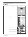
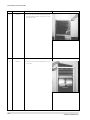
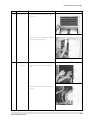
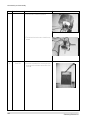
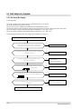
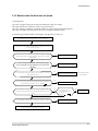
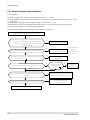
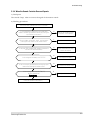
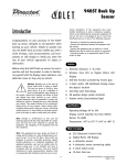
1
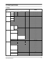
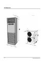
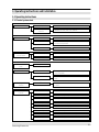
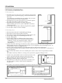
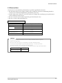
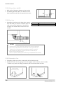
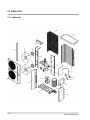
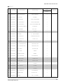
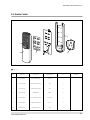
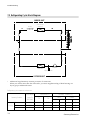
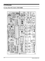
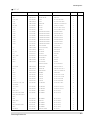
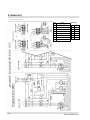
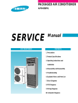
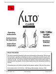
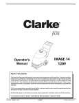
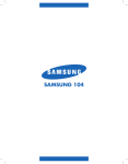
ROOM AIR CONDITIONER
AP500PF
SERVICE
Manual
AIR CONDITIONER
CONTENTS
1. Precautions
2. Product Specifications
3. Operating Instructions and
Installation
4. Disassembly and Reassembly
5. Troubleshooting
6. Exploded Views and Parts List
7. Block Diagrams
8. PCB Diagrams
9. Wiring Diagrams
10. Schematic Diagrams
1. Precautions
1) Turn off the the power.
Be sure to turn off the power before attempting to repair the
unit such as the disassembly of the unit.
Turn off the sub power switch separately installed.
2) Be careful of electric shock
When checking the circuit with the power connected in
unavoidable circumstances, take special care not to touch the
live parts. There is a danger of electric shock.
3) Use of appropriate parts
Be sure to use the genuine parts of the relevant model when it
is necessary to replace parts. (Replace parts instead of repairing with regard to the malfunctioning of electric contact areas.
Never attempt to modify the unit. It is extremely dangerous
for the consumer to attempt to repair the unit on his(her)
own.)
4) Use of proper tools
Use appropriate tools for repair, and use measuring equipment after accurate calibration. Using worn tools may result
in problems, including poor contact and poor connection.
5) Avoid damage to electric wire or electric cord.
Check the electric cord or electric wire for any damage during
repair.
Be sure to replace it if damaged.
6) Avoid intermediate connection of the electric cord.
Never attempt to make an intermediate connection by cutting
the middle area of the electric cord or make a connection to
the power receptacle as it is very dangerous, causing problems
or fire.
No connection with the power receptacle
7) Checking of insulation
Be sure to check the insulation resistance after completion of
the assembly work.
(Check whether the insulation resistance of the electric wire
and grounding terminal is over 30MΩ by using the insulation
resistance tester, and then connect the power source.)
8) Checking of grounding
Check the grounding condition, and perform repair if poorly
grounded.
9) Checking of installation condition
Check the installation condition of the unit, and perform
repair if there is any defective area.
If the unit remains in an unstable installing condition, install it
at a new site.
10) Be careful of children
As the repair of the unit involves a lot of dangerous elements,
do not allow children to approach nearby during repair work.
Cleaning
Upon completion of the repair, clean the air
conditioner and surrounding area, and
inform the customer of completion of the repair.
Samsung Electronics
1-1
2. Product Specifications
2-1 Table
Model
ITEM
Size
Unit
Width x Height x Depth
Packed
Width x Height x Depth
Unit
Width x Height x Depth
Outdoor unit
Packed
Width x Height x Depth
Piping
Packed
Width x Height x Depth
Weight
Unit
Indoor unit
Packed
Unit
Outdoor unit
Packed
Piping
Packed
1.
Cooling
capacity
Electric
characteristics 2. Power consumption(Cooling)
3. Current consuption(Cooling)
4. E.E.R
5. Noise
Indoor unit
Turbo
(Cooling/
High
Heating)
Medium
Low
Outdoor unit
Indoor unit 1. Evaporator
Construction
Fin
Capillary tube
2. Blower motor
No. of polarities
Capacitor
RPM
Outdoor unit
Indoor unit
3. Blower
4. Motor swing
5. Fuse
1. Condenser
2. Refrigerant volume
3. Compressor
4. Fan motor
5. Fan
6. Service v/v
Samsung Electronics
mm
mm
mm
mm
mm
kg
kg
kg
kg
kg
BTU/h
W
A
BTU/Wh
dB
dB
dB
dB
dB
Row x Step
Turbo
High
Medium
Low
Type
Construction
Fin
V/A
Row x Step
g
Maker
Model
Type
Capacitor
OLP
No. of polarities
Capacitor
RPM
Type
High pressure side
Low pressure side
AP500PF
590 x 1810 x 400
704 x 1925 x 600
930 x 1240 x 385
1200 x 1370 x 540
760 x 165 x 760
75
83
104
114
17
50,000
5,100
16/9.5A
9.8
56
55
54
53
65
4 x 30
WAVE 1.7
ø1.2
6P
450VAC, 6µF
1000
950
900
850
SIROCCO
220V, 6RPM
250V, 5A
2 x 24, 2EA
WAVE 1.7
3800
COPELAND
CRL3-0351
Recipro
450VAC, 40µF
8P
4µF
750
PROPELLER
3/8 inch
3/4 inch
2-1
2-2 Dimensions
Unit : mm
400
385
930
590
2-2
Samsung Electronics
3. Operating instructions and Installation
3-1 Operating Instructions
3-1-1 Control system chart
Operation
Main switch operation
Operation of remote
controller
Function selection
Fan speed
selector mode
Operation of auto, cool and fan
Operation of turbo, auto, cool, and fan
Auto mode
Control of fan motor step according to current temperature
Cool mode
Control of cool according to the difference between current
and desired temperature
Fan mode
Operation of indoor fan motor only
Manual 3-step
Auto
Airflow selector
mode
Left-right turn
Convenience function
Turbo operation
High medium, low
Control of fan motor step according to current temperature
Turbo-operating compressor and powerful operating fan
motor(30minutes)
Convenience reservation
Reserve function which is off after on time of 1, 2, 3, 4, or 5
hours
Self-diagnosis
function
“E1”
Displayed at the time of indoor temperature sensor open
or short
LED display
function
Function selector
Selection of fan speed
Low, medium, high lamp
Selection of airflow
Left-right lamp
Current temperature
Indoor temperature display
Desired temperature
Desired temperature display
Fan speed diagram
Low, medium, high, turbo lamp
Convenience reservation
Current time
Samsung Electronics
Auto, cool, fan lamp
Reserve lamp and reserve time display
Current time display
3-1
3-1-2 Key type and functions
3-1-2(a) PANEL key type and functions
Key name
On/off
Mode selection
Fan speed
selection
Temperature(time)
setting(up)
Temperature(time)
setting(down)
Change of display
Key operating function
Start and end of operation
- ON 1 time = operation start, ON again = operation end.
- No continued operation
Change of the operation mode
- Each time the button is pressed(ON), the mode is changed in the following order:
“auto cool fan”(standard=auto)
- No continued operation
Setting of the indoor fan motor speed
- Each time the button is pressed ON, the mode is changed in the following order:
“low medium high”(standard=high)
Increase the desired temperature(current time)
- Temperature: When pressing the button(ON) one time,
the desired temperature is increased by the unit of 1°C.(18°C- 30°C)
- Time: When pressing the button(ON) one time, the time is increased by 1 minte.
If the “on” button is pressed continuously, the time is increased by 10 minutes.
- One short, and continued operation
Decrease the desired temperature (current time)
- Temperature: When pressing the button(ON) one time,
the desired temperature is decreased by the unit of 1°C. (18°c- 30°C)
- Time: When pressing the button(ON) one time, the time is decreased by 1 minute.
If the “on” button is pressed continuously, the time is decreased by 10 minutes.
- One short, and continued operation
The temperature and current time can be changed.
- If the “on” key is pressed 1 time, current temperature
and desired temperature are displayed.
- If the “on” key is pressed 1 time, current time is displayed.
Key type
TACT
TACT
TACT
TACT
TACT
TACT
* Operating functions
Button for speed selection: When pressing Fan display: The fan is dis- Time and temperature display: Cool display: The door temperathe button, the mode is selected in the
played in the order of turbo, Current time, reserve time, and ture is sensed and the button is
order of high-medium-low.
high, medium, and low.
temperature are displayed.
lighted when cooling is begun.
Display change button: When the button is pressed, current time and temperature are displayed continuously.
3-2
Up/down button: It can regulate current
time and desired temperature.
Function selector disLeft-right turn play: Current mode of
display.
operation display.
Function selector button: when pressing the button, the mode
can be selected repeatedly in the order of auto-cool-fan.
Sensor to perceive remote
controller: It can receive
orders from remote controller.
Convenience reserve
button: It can stop the
operation automatically.
Reserve display:
Convenience reserve
operation is perceived
when ordered to do so.
On/off button.
Operation display lamp:
When the power is first
applied, the lamp will
blink, but will turn on
when operation begins.
Samsung Electronics
3-1-2(b) LED display operating spec.
Lamp name
Operation lamp
Operating spec.
- When the power is applied, the lamp goes on and off in an interval of 0.5
seconds.
- If the operation is changed to “on”, the lamp stops turning on and off and
continues to remain on.
- If the operation is changed to “off”, then LED off.
Cool lamp
- When the compressor is activated: ON
- When the compressor is stopped: OFF
Timer lamp
- During reservation: ON
- Reservation ended or cancelled: OFF
Reservation-timer
lamp
- During reservation-timer display: ON
- During current time and temperature: OFF
Current temperature
lamp
- During current temperature display : ON
- During current time and time display: OFF
Desired temperature
lamp
- During desired temperature display: ON
- During current time and reserve time display: OFF
Fan speed display
lamp
- During on operation: ON
- During off operation: OFF
Current time lamp
- During current time display: ON
- During reserve time and temperature display: OFF
Turbo lamp
- During turbo operation: ON
- During turbo operation is ended or cancelled: OFF
Fan speed selector
lamp
Left-right lamp
- Low: 2 lines ON
- Medium: 4 lines ON
- High: 5 lines ON
- Turbo: 6 lines ON
- During left-right turn operation: ON
- During left-right turn ends: OFF
Auto lamp
- During auto operation: ON
- Other modes: OFF
Cool lamp
- During cool operation: ON
- Other modes: OFF
Fan lamp
- During fan operation: ON
- Other modes: OFF
Samsung Electronics
3-3
3-2 Installation
3-2-1 Selection of Installation Place
3-2-1(a) Indoor Unit
• Install the unit at a place close to the wall facing the outside
as it is necessary to perform piping connection with the outdoor unit.
- It is effective to install the unit at a window side to ensure
uniform distribution of indoor temperature.
• Install the unit at a place where there is no obstacle against
the wind around the air inlet and air outlet.
• Install the unit horizontally at a stable, rigid place.
(When installing the unit at a place subjected to vibration,
noise may occur.)
• Avoid a place near the door which is frequented by people.
• Avoid a place subject to direct sunlight.
Top view
Above 50cm
Side view
Above 20cm
3-2-1(b) Outdoor Unit
•
•
•
•
•
•
Place free from the risk of combustible gas leakage.
Place which can bear the weight of the unit.
Place which can bear the fixing strength of the outdoor unit.
Avoid a place subject to oil (including machine oil).
Avoid a saline place.
Avoid a place subject to sulfide gas (hot spring zone).
(When installing the unit at such special environmental
conditions, it may cause machine trouble. When it is
Above 100cm
unavoidable to use such places. It requires special
maintenance.)
• A place where the discharge air and noise of the outdoor unit do not disturb the neighborhood.
(Take special care not to cause any inconvenience to your neighbors when installing the unit on
the borderline with your neighborhood.)
• A place where strong wind does not head against the air outlet of the outdoor unit.
(If a strong wind heads directly against the air outlet at the time of cool operation, a safety device
can be operated.)
• Do not install the outdoor unit at an unstable place such as outer wall of an apartment or building.
The outdoor unit may fall down, causing severe personal or property damage or loss.
* If there is any unavoidable reason to install the unit at such
a place, take the following measures against the wind;
1. When installing the unit at a roadside concentrated with
buildings, install it parallel with the road.
2. Install the unit so that the air outlet faces toward the wall
at a place such as rooftop, which may be subjected to
strong wind.
Strong wind
Wall
Roof top
* The outdoor unit should be installed in accordance with the service space.
Above 15cm
Above 50cm
Space for piping
and wiring
Above 50cm
Above 15cm
Above 15cm
The air inlet faces toward the wall.
3-4
Above 30cm
Space for piping
and wiring
The air outlet faces toward the wall.
Samsung Electronics
Installation Method
3-2-2 Electrical Work
The electrical work should be performed by a specialist qualified for the work.
• Use the three phase power supply, and be sure to install the sub power distributing board for
exclusive use with the unit(separately purchased by the user).
* Avoid octopus-type wiring as it can cause a drop in voltage, thus resulting in poor performance
of the automatic control circuit.
• Be sure to install circuit breaker (separately purchased by the user).
• Be sure to connect the grounding wire.
Electric power spec
Power
Ampere of breaker
Knife switch
Switch
Fuse
Size of grounding wire
Min. size of electric wires from/to
the indoor/outdoor unit
Size of electric input wires
3phase 3wires 220V / 3phase 4wires 380V
50 A
30 A
30 A
2.0 mm2
0.75 mm 2
5.5 / 3.5 mm 2
CAUTION
• Be sure to use the wires, and switches or fuses of power distribution board are qualified
and fulfill the specification.
• Be sure to install knife switch or circuit breaker on the power distribution board.
• The electrical and grounding work should be performed as per “ technical specification
of electrical facilities ” and “ specification of internal wiring ”.
• Be sure to connect main electrical input wires with bolted connectors using compressed terminal.
Applicable voltage 220V
Applicable voltage 380V
Samsung Electronics
198V ~ 242V
342V ~ 418V
3-5
Installation Method
3-2-2(a) When connecting 3Phase 4wires 380V AC
1. Remove cover of electric box on side panel of outdoor unit.
2. Connect electric input wires (R,S,T,N) to each terminal (R,S,T,N) of the electric box on outdoor
unit respectively.
(Input wires are purchased by the user separately.)
3. Connect electric wires (red, white, black) to each terminal (red, white, black) on indoor and outdoor unit respectively.
OUTDOOR SIDE
Power terminals on the outdoor unit
Knife switch or
automatic circuit
breaker
Red
White
Black
Red
White
Black
Green
Electric input wires
Indoor / outdoor unit
connecting wire
CAUTION
• Be sure to connect electrical wires correctly, if not it can cause a trouble.
* Be sure to fix wires from/to the indoor and outdoor unit on the piping insulated.
Avoid wires contact to bare pipe or valve directly without any insulated spacer.
3-6
Samsung Electronics
Installation Method
3-2-2(b) When connecting 3Phase 3wires 220V AC
1. Remove cover of electric box on side panel of outdoor unit.
2. Connect electric input wires (R,S,T) to each terminal (R,S,T) of the electric box on outdoor unit
respectively.
(Input wires are purchased by the user separately.)
3. Connect electric wires (red, white, black) to each terminal (red, white, black) on indoor and outdoor unit respectively.
OUTDOOR SIDE
Power terminals on the outdoor unit
Knife switch or
automatic circuit
breaker
Red
White
Black
Red
White
Black
Electric input wires
Samsung Electronics
Indoor / outdoor unit
connecting wire
3-7
Installation Method
3-2-3 Installation Method
3-2-3(a) Installation Procedures
1. Open the inlet grille, and remove the flare nut.
2. Bend the connection pipe to an appropriate length using the spring bender depending
upon the installation place.
- Allowable pipe length : Maximum 25m
- Allowable pipe drop distance : Maximum 15m
- Make no more than ten bending points on the pipe
• When the pipe length is in excess of the standard pipe length of 5m, add the refrigerant
(R-22) of 50g for each additional 1m.
CAUTION
• If the pipe is lengthened, the performance of the unit is degraded, and the service life is shortened.
Therefore, the pipe length should be as short as possible (less then 15m).
Outdoor
unit
Indoor
unit
Indoor
unit
Outdoor
unit
3. Install the high pressure pipe to the heat exchanger liquid pipe, and the low pressure pipe to the
heat exchanger gas pipe respectively using the flare nut, taking care not to cause any leakage of
refrigerant.
4. Be sure to insulate the pipe with appropriate insulation material.
5. Insert the drain hose into the drain pipe, and connect them by tying them to the cable tie to prevent any water leakage.
6. After completion of the installation, check the connecting area for any gas leakage.
7. Wind a finish tape when the wiring of the refrigerant pipe, the unit, and the drain piping are completed.
Outdoor unit
checking area
Indoor unit
checking area
3-8
Samsung Electronics
Installation Method
3-2-3(b) Connection of Refrigerant Piping
Flare Processing
1. Cut the pipe using the pipe cutter.
Oblique
Roughness
Burr
2. Insert the flare nut into the pipe, and then perform the flare processing.
Outer Diameter
ø 9.52mm
ø 19.05 mm
A ( out / in)
1.7 / 1.0 (mm)
2.2 / 1.5 (mm)
• Unproper flaring
Inclined
Surface
damaged
Cracked
Uneven
thickness
Pipe Bending
1. Perform bending of the pipe using the bender which has a specified bending radius.
2. Be sure to take full care to perform bending of the pipe successfully at one time.
Bending and unbending the pipe more than twice makes the bending work increasingly difficult.
3. You may use the spring inserted into the gas pipe instead of the bender to bend the pipe.
4. When you bend the pipe using the spring, hold the pipe with both hands to prevent any distortion, and secure a minimum bending radius of more than 100mm.
Spring
Tightening of Connection Parts
•
Align the center of the connection piping, and tighten the flare nut
by turning it with hand. Then tighten it again using the spanner in
the direction as shown in the figure.
Outer Diameter
ø 9.52mm
ø 19.05mm
Tightening Torque
400 kg • cm
700kg • cm
Samsung Electronics
Final Torque
450 kg • cm
750kg • cm
Remarks
3-9
Installation Method
3-2-3(c) Drilling a Hole in the Wall
•
•
Drill a hole of 70mm in diameter to the outside.
The drilling should be done at a distance of less
than 150mm from the floor facing the indoor unit.
ø70mm
Less than
150mm
3-2-3(d) Drain Hose
•
Extend the drain hose to the drain hose connected to the drain pan, and fix it with the tape or a
cable tie to prevent separation. Then make a
covering of it so that water can not flow outwardly.
Drain pan
Piping Material
Insulator
Vinyl Chloride(Outer diameter ø 16mm)
Foamed Polyethylene
Insulation
Band
Drain hose
Indoor and
outdoor
connection
CAUTION
1. As the draining is of natural drain type, make the drain hose direct downward.
2. If there is any foreign substance in the drain plate, it may clog the drain pipe.
Therefore, be sure to remove the foreign substance inside after installation.
3. After completion of installation, be sure to pour water into the drain pan,
and then check the draining condition.
(There is no problem in draining when the draining is completed within 20 seconds.)
3-2-3(e) Rat-prevention Cover
•
•
The piping of this unit can be connected to the left and rear side.
When you hit the area for piping connection slightly with a hammer, a hole is made.
- If there is any reason to change connection, fill in hole with ruber cabi slot.
Holes for piping
connection (2 points)
3-10
Samsung Electronics
4. Disassembly and Reassembly
4-1 Indoor Unit
No
Parts
Procedure
1
Indoor unit
2
Inlet grille
1) Open the inlet grille and remove the
connection ring.
3
Main PCB
1) Separate the PCB connect wire after
separating the control box cover.
Remarks
2) Separate the connection wire to separate the
front cover and duct.
3) The main PCB should be separated by turn
over the mountain tab.
Samsung Electronics
4-1
Disassembly and reassembly
No
Parts
Procedure
4
Font cabi
1) The front cabi should be separated by giving
strength downward after loosening 2 screws
at the lower end.
5
Plate top
1) The plate top should be separated by loosening screws.
4-2
Remarks
Samsung Electronics
Disassembly and reassembly
No
Parts
6
Ass’y grille out
Procedure
Remarks
1) First loosen screws at left and right sides of
grille out.
2) Then the ass’y grille out should be separated
by giving strength upward ( ↑).
7
Ass’y duct
1) First loosen the 4 screws at left and right
sides.
2) Then the ass’y duct should be separated by
lifting it.
Samsung Electronics
4-3
Disassembly and reassembly
No
Parts
8
Evaporator
Procedure
Remarks
1) First separate the cover after loosening the
screws fixed at evap cover R.
2) Ten separate the 3 screws fixed at cabinet
BKT of evaporator BKT.
3) Evaporator should be separated by flinging
ahead.
4-4
Samsung Electronics
Disassembly and reassembly
No
Parts
Procedure
9
Motor
1) When the ass’y duct should be separated
from the motor, the 2 bracket should be separated first.
Remarks
2) Then the bolts fixed at the blower and motor
shaft should be separated.
3) Then the screws binding the holder top blower and duct should be separated.
4) The duct of one side should be separated as
the picture shows after loosening the upper
binder.
5) The binder of the motor and the duct should
be separated.
Samsung Electronics
4-5
Disassembly and reassembly
No
Parts
Procedure
Remarks
6) Then the motor should be separated.
7) The bracket fixed at the motor should be separated.
10
4-6
Panel PCB
1) Should be separated after loosening the insulating material and binders at the back of the
front side.
Samsung Electronics
Disassembly and reassembly
4-2 Outdoor Unit
No
Parts
1
Outdoor unit
Procedure
Remarks
1) Packaged air conditioner outdoor unit
2) The binders of the front side should be separated.
3) The flank and the binders should be separated from each other.
2
Control box
Samsung Electronics
1) Connect distributed wires in the control box.
4-7
5. Troubleshooting
Troubleshooting
First,
Items to be checked first
Second,
Check the corrective actions in the case of occurrence of self-diagnosis mode
Third,
When the trouble is not related to the 1st or 2nd items above, check the troubled area in
detail in accordance with the fault analysis method by symptom.
5-1 Items to be checked first
1) Is the supply voltage appropriate?
The supply voltage: should be AC 187V-AC 253V/60Hz
2) Is the connecting wire between the indoor unit and outdoor unit appropriate?
The indoor unit and outdoor unit should be connected with each other by 3 cables.
Be sure to check whether the cables for the indoor unit and outdoor unit are securely connected
by the same terminal number.
3) When any claim occurs according to the contents of the table below, it is not related the trouble of
the air-conditioner at all.
No.
1
Operation of air-conditioner
Description
The compressor does not operate when the
When restarting the compressor, the operation of the compressor is
desired temperature is set at a lower
delayed for 3 minutes to protect the compressor.
level than the room temperature.
Normal operation is possible only after an elapse of 3 minutes,
even when applying the initial power.
2
3
The fan speed cannot be controlled
The fan speed is automatically set at the
during auto or turbo operation.
MICOM during auto and turbo operation.
The temperature is not set during auto,
The desired temperature is automatically set at the MICOM
fan or turbo operation.
during auto and turbo operation.
The fan operation circulates the room air without temperature control.
5-2 Self-diagnosis and corrective actions
No.
1
Temperature
display
E1
Samsung Electronics
Cause
Corrective actions
Room temperature sensor
Replace the room temperature
short
sensor
Room temperature
Check the main PCB pattern
sensor open
and components for short or open
5-1
5-3 Fault Analysis by Symptom
5-3-1 No Power (No display)
1) Checkpoints
(1) Is the voltage of the power source normal?(AC 187V - AC 253V)
(2) Is the power line in good contact?
(3) Check the power fuse(F701, F702) and PCB fuse(F101) for open.
(4) Are the primary and secondary sides of the power-trans in good contact with the connector?
(5) Is the output voltage of REG1(KA7812) normal?(DC 11.5V - DC 12.5V)
(6) Is the output voltage of REG2(KA 7805) normal?(DC 4.5V - DC 5.5V)
2) Checking procedures(after checking the checkpoints of clause 1)
Turn off the power, and then turn it on in 5 seconds.
Is the room temperature displayed on the temperaturre
indicator, the display lamp turned on, and the panel
shutter down when pressing the on/off button.
Y
Then it is normal operation.
N
Is the voltage or the power trans AC 18V-21V secondary
side(CN11) normal?
N
Check and replace the power trans.
Y
Is the output voltage of REG1 and REG2 normal?
(REG1=12V, REG2=5V)
N
Y
Is the output wave at the MICOM(IC1) pin (No. 33~40) a
square wave?
N
Remove the shorted parts of the
power terminal.
Replace the defective parts.
(D101-104, REG1, REG2)
Check and replace the MICOM(IC1).
Y
Is the output wave at IC4 pin No. 13~18 a square wave?
N
Check and replace the IC4.
Y
Is the harness between the main PCB and panel PCB well
connected?
N
Reassemble or replace the harness
after checking it.
Y
LED display or panel PCB defective.
5-2
Samsung Electronics
Troubleshooting
5-3-2 When the Indoor Fan Motor does not Operate.
1) Checkpoints
(1) Is the voltage of the power source normal?(AC 187V-AC 253V)
(2) Is the indoor fan connector (CN71) in good contact?
(3) Is the starting condensor of the fan motor in good contact with the terminal?
(4) Is the resistance at both ends of the relay coil approximately 400L?
2) Checking procedures(after checking the checkpoints of clause 1)
Turn off the power, and then turn it on in 5 seconds.
Operate the on/off button, and operation mode key, and place
it in the “FAN” position.
Does the airflow volume of the indoor fan motor change
when converting into high, medium, and low by the FAN
speed key?
Y
Then the indoor fan motor is normal.
N
Do the RY3(high), RY4(medium), and RY5(low) operate
when converting into high medium and low by the FAN
speed key.
Y
Then the relay is normal.
N
Is the resistance at both ends/of the relay(RY 3, 4, 5) coil
approximately 400L?
N
Check the resistance level after
Then replace the relay when resistance is 0¥ or i~.
turning off the power.
Y
Is it “high” when checking the output wave for airflow at
the MICOM(IC1) pin No. 54, 55, and 56?
N
Then check and replace the MICOM(IC1).
Y
Is the voltage at both ends of the relay for each airflow at
the time of selecting the fan speed(high/medium/low) DC
12V?
N
N
Then check and replace the IC3.
Y
Y
Is the voltage at both ends/of indoor fan motor AC 220V?
Is it low when checking
the output wave for
each airflow at the IC3
pin No. 11, 12,
and 13?
N
Then check the wiring harness for open.
Check and replace the indoor fan motor.
Samsung Electronics
5-3
Troubleshooting
5-3-3 When the Compressor Does not Operate
1) Checkpoints
(1) Is the voltage of the power source normal?(AC 187V - AC 253V)
(2) Is the desired temperature set at a higher level than the current temperature at the time of “Cool”
operation?
(3) Is the power-in good contact with the comp. connector(GT 1, 2, 3)?
(4) Check the wirings of the outdoor and indoor unit for a wrong connection or poor contact.
(5) Isn’t the compressor in a 3-minute stand-by state?
2) Checking procedures(after checking the checkpoints of clause 1)
Turn off the power, and then turn it on in 5 seconds.
Check whether the relay(RY1) is turned on and the compressor is operated in 3 minutes after starting the
“COD” operation by activating the on/off button and
operation made key.
N
Y
Then the compressor and relay are normal.
N
Is the resistance at both ends/of the relay(RY 1) coil approximately 400Ω?
Replace the relay when the
resistance is 0Ω or ∞.
Y
Is it “high” when checking the output wave of the MICOM
(IC1) pin No. 6?
N
Y
N
Is the voltage at both ends/of the relay(RY1) coil DC 12V?
Check and measure
the resistance
value after turning
off the power.
Then check and replace the
MICOM (IC1).
Is it “low” when
checking the output
wave of the IC 3
No. 16.
N
Then check and
replace the IC 3
Y
Y
Is the voltage at both ends/of the electronic contactor coil
AC 220V?
Y
Is the voltage at both ends/of the electronic contactor terminal AC 220V?
N
N
Then check the wiring of indoor and Then
check the wiring of indoor and or open.
Then check and replace the
electronic contactor
Y
Replace the compressor.
5-4
Samsung Electronics
Troubleshooting
5-3-4 When the Remote Controler Does not Operate
1) Checkpoint
The sounds “beep” when it receives the signal of the remote control.
2) Checking procedures
Turn off the lower, and then turn it on in 5 seconds.
Is room temperature displayed on the temperature
indicator and does the operation start when pressing the
on/off button on the panel?
N
Refer to the checkpoint when
the power is not supplied.
Y
Does the indoor unit sound a “beep”, and stop when
pressing the on/of button on the remote control?
Y
Then it is in normal operation.
N
Is the panel PCB connector(CN2) properly connected to
the main PCB connector(CN91)?
N
Repair and replace the panel
harness as required.
Y
Is the voltage of the battery over DC 2.5V?
N
Then replace the battery.
Y
Is the unit normally operated when pressing the on/off
button after replacing the remote control?
N
Then replace the remote control.
Y
Is the receiving wave of the MICOM(IC1)
No.2b a square wave?
N
Then replace the receiver module.
Y
Check and replace the MICOM(IC1).
Samsung Electronics
5-5
5-4 PCB Inspection
5-4-1 Inspection Precautions
1) Be sure to check whether the AC sub power switch is removed when removing the main PCB or
panel PCB.
2) Do not hold the outside of the main PCB or panel PCB with the hand or aply excessive force to it.
3) When connecting or removing the connector to the main PCB or panel PCB, do not pull the lead
wire, but hold the entire assembly with the hand.
5-4-2. Inspecting procedures
1) When there is any trouble with the main PCB or panel PCB, check the connector for a poor connecting and the PCB or copper-clad pattern for separation.
2) The PCB is composed of the following two parts.
• Main PCB: The main PCB is composed of the MICOM and peripheral circuit, relay drive sensor
drive circuit, DC 5V power circuit, DC 12V power circuit and buzzer drive circuit, etc.
• Panel PCB: The panel PCB is composed of the LED display key and remote control.
5-4-3. Detailed inspection procedures
NO
5-6
NO
NO
NO
1
Turn off the sub power switch,
and then check PCB fuse.
1) Is the fuse blown?
1) Overvoltage?
2) Indoor fan motor short?
2
1. Apply the supply voltage
2. When power lamp and LED display
operate afterpressing the on/off
button, it is not related to items
1)~4).
Check the supply voltage
1) Is the voltage between both
ends/of the trans connector(GT4,5
AC187V ~ AC 253V?
2) The voltage between both
terminals/of the CN11 AC 18V~AC
21V.
3) Is the voltage between both
terminals/of the REG1 (KA 7812)
out and GND DC 12V?
4) Is the voltage between both
terminals/of the REG2 (KA7805)
out and GND DC 5V?
1) Power cord faulty, poor connection
of indoor and outdoor unit, fuse
blown, wrong wiring of power cables.
2) Power trans faulty power circuit
faulty.
3) Power circuit faulty load short.
4) Power circuit faulty, load short.
3
Set the unit to “cool” operation mode
by the “on/off” button and mode
selector key.
1. Fan operation
2. Fan speed high, medium, low.
1) The compressor does
not operate.
1) The relay(RY1) for driving the
electronic contractor does not
operate.
2) Electronic contactor faulty.
4
Set the unit to “fan” operation mode
by the “on/off” button and mode
selector key.
1. Fan operation
2. Fan speed high,
medium, low.
1) Is AC 220V applied between the
1) Indoor fan motor faulty.
com terminal and the high, medium, 2) Starting condenser faulty.
and low terminal at the indoor fan
motor connector? (when selecting
each fan speed)
2) Indoor fan motor does not turn.
Samsung Electronics
6. Exploded Views and Parts List
6-1 Indoor Unit
6-1
Samsung Electronics
Exploded Views and Parts List
■ PART LIST
Q’TY
No
1
2
3
4
●
●
5
6
7
8
9
10
11
12
13
14
15
●
16
17
18
19
20
●
21
22
23
24
25
26
27
28
29
30
31
32
●
●
33
34
35
36
37
38
39
40
41
42
43
44
45
46
47
48
CODE-NO
DB70-10271A
DB90-10561A
DB90-20171B
DB91-90012B
DB90-40113A
DB90-40113L
DB90-10175A
DB64-50076A
DB63-10027A
DB63-10432A
DB93-40232L
DB93-40232S
DB64-30011D
DB64-50019A
DB64-50020A
DB64-50069A
DB61-30501A
DB74-10079A
DB92-10007B
DB67-90005A
DB61-30108A
DB61-30109A
DB64-10035A
DB64-10036A
DB92-10298A
DB64-10034A
DB64-50075A
DB61-40034A
DB61-40235A
DB66-30156A
DB66-60026A
DB68-70001A
DB95-20065E
DB61-40234A
DB92-20017A
DB61-40037A
DB66-30070A
DB94-30143A
DB94-30143B
DB61-40233A
DB90-40112B
DB63-10431A
DB90-40112A
DB61-30507A
DB95-20136A
DB95-20136B
DB67-50003A
DB61-10023A
DB26-10070A
DB93-10468A
DB63-10033A
DB96-40159A
DB96-40164A
DB63-10430A
DB96-10535A
DB96-10559A
DB96-50082A
DB96-50083A
DB61-40052A
DESCRIPTION
PLATE-TOP
ASS’Y-CABI IN
ASS’Y-BASE IN
ASS’Y-DRAIN PART
ASS’Y-CABI FRONT
ASS’Y-CABI FRONT
ASS’Y-CABI FRONT IN
DECORATION-LOW
COVER-CONTROL
COVER-CONTROL
ASS’Y-CONTROL PANEL
ASS’Y-CONTROL PANEL
BRAND-SAMSUNG
KNOB-A
KNOB-B
DECORATION-DIE
BRACKET-DECO LOW
FILTER-PRE
ASS’Y-GRILLE IN
BASKET-PEMOCON
BASKET-GRILL LF
BASKET-GRLL RH
GRILLE INLET UP
GRILLE INLET LOW
ASS’Y-GRILLE OUT
GRILLE OUTLET
DECO UP
HOLDER OUT GRILL
HOLDER-BLADE UP
BLADE-V
LINK-BLADE V
CAM BLADE
ASS’Y-MOTOR SWING
HOLDER-BLADE LOW
ASS’Y BLADE H
HOLDER-BLADE
BLADE-H
ASS’Y-BLOWER IN
ASS’Y BLOWER IN
HOLDER-TOP BLOWER
ASS’Y-CASE DUCT R
COVER-BELL MOUTH
ASS’Y CASE DUCT L
BRACKET-MOTOR IN
ASS’Y-MOTOR IN
ASS’Y-MOTOR IN
BLOWER
CASE-CONTROL
TRANS-POWER
ASS’Y-PCB MAIN
CSVER-CONTROL CASE
ASS’Y-EVAP IN
ASS’Y-EVAP IN
COVER-EVAP R
ASS’Y-TUBE INLET PART
ASS’Y-TUBE INLET PART
ASS’Y COLLECTOR IN
ASS’Y COLLECTOR IN
HOLDER-THERMISTOR
Samsung Electronics
SPECIFICATION
SECC-P, -, -, -, -, SC-94445T
AP-1100, L1810590°ø363
SAH-2017, 2517, SECC-P(20/20)
AP-1604CR, AP-1100
AP-500PF
SA-165CH, LAMINATED
ABS, -, -, ABS, -, -, EPS, T8, WHT, -, AP-1100
AP-1100, AP-500PF
KOAL, T1.6, W11.5, L70, BLK, ABS, CR, SAH-165CH, ABS, CR, SAH-165CH, ABS, GRY, SAH-165CH, SECC-P(20/20), T2.0, SC-4
PE, T0.3, AP-110
SAH-165CH, SAH-2016/2516
SC-9444ST, SAH-165CH
SC-94445T, SAH-165CH
ABS, SAH-2016/2516
ABS, SAH-2016/2516
AP-1100, ABS, SAH-2016/2516
ABS, SAH-2016/2416
SECC-P(20/20), BLK
SGCCM, T1, -, L564
PC ABS, T3, 5, PC ABS, T2, 12, -, -, POM
516RPM M2LA49ZR32, SGCCM, T1, -, L564
SAH-2016/2516
ZN-DC1, -, -, SAH-165CH
SECC-P, T0.5, 230, AP-1100, 6uF
AP-1300, 6uF
SGCCM, T2.0, -, AP-1100
AP-1100, T0.8
SGCCM, T0.8, -, -, M, AP-1100
AP-1100, T0.8
SGCCM, T2.0, -, AP-1100
AP-1100, OSM-1508SAC
AP-1300
ABS, -, ABS, -, -, BLK, -, DC17, AC230, -, -, -, DC17, DC0.6A
AP-1100/1300, ABS, -, BLK, -, AP-1100, 3°ø30, 1.7WAVE
AP-1300, 4°ø30, 1.7WAVE
SGCCM, T0.8, -, -, L749 W 77
AP-1100, 1.3/600, 750
AP-1300, 1.2/850/900/950/1000
AP-1004CR
AP-1604CR, ABS, -, WHT, -
AP-500PF
1
1
1
1
1
1
1
1
1
1
1
2
1
1
1
1
1
1
1
1
1
1
1
1
2
1
5
1
1
1
1
4
2
1
1
1
1
4
1
3
1
2
1
1
1
1
1
1
1
1
1
REMARKS
5~12 ASS’Y
5~12 ASS’Y
16~20 ASS’Y
21~29 ASS’Y
31, 32 ASS’Y
33~39 ASS’Y
33~39 ASS’Y
6-2
6-2 Outdoor Unit
6-2-1 Outdoor Unit
6-3
Samsung Electronics
Exploded Views and Parts List
■ PART LIST
Q’TY
No
DESCRIPTION
CODE-NO
SPECIFICATION
REMARKS
AP500PF
1
DB90-10565A
ASS’Y-CABI OUT AIR
WELD GUARD FAN
1
2
DB63-30028C
GUARD-INLET
SC-91438T, -
1
3
DB67-50067A
FAN-PROPELLER
AS+GF20, D495, 4BLADE
2
4
DB95-20137A
ASS’Y-MOTOR OUT
AP-1100, OSM-6508SRC
1
5
DB95-20137B
ASS’Y-MOTOR OUT
AP-1100, OSM-6508SRC WIRE
1
6
DB90-30028E
ASS’Y-MOUNT MOTOR OUT
APE-1600CR, -
1
7
DB61-40088A
HOLDER-FRAME
SGCC1, T1.6, -, -
1
8
DB93-40272A
ASS’Y-CONTROL OUT
AP-1100
1
9
DB67-30025A
PARTITION
T1, -, 389.17°ø1239.46
1
10
DB90-20085K
ASS’Y-BASE OUT
AP-3508, M8 WELD BOLT
1
11
DB99-10091A
ASS’Y VALVE 3/8"
C1220T-0, 3/8"
1
12
DB99-10081B
ASS’Y-VALVE
13
DB90-10071B
ASS’Y-CABI OUT LW SD
SECC-P(20/20), T0.8
1
14
DB90-10085B
ASS’Y-CABI OUT UP SD
SECC-P(20/20), T0.8
1
15
DB72-50556A
INSU SOUND
T12, W940, L380
1
16
DB95-10279A
ASS’Y-COMP
CR42K6
1
17
DB73-10008A
GROMMET-MOUNT
BROWN
1
18
DB90-10369D
ASS’Y-CABI OUT B
AP-1004/1604CR, -
4
19
DB62-31553A
TUBE-DISCHARGE
C1220T-0, 9.52
1
20
DB62-31554A
SUCTION TUBE
C1220T-0, 19.05
1
21
DB62-10002C
DRIER
C1220T-0
1
22
DB96-30248A
ASS’Y-COND UP
1.7 WAVE
1
23
DB96-30249A
ASS’Y-COND LOW
1.7 WAVE
1
24
DB98-20057A
ASS’Y-PLATE TOP
AP-1004/1604CR, -
1
25
DB63-30110C
SCREEN-GUARD
P.E.H 100%, T2.5, -, -
1
26
DB67-90017B
HANDLE
ABS, -, SC-90073R
1
Samsung Electronics
1
6-4
Exploded Views and Parts List
6-2-2
■ Parts List
No
CODE NO
Description
Specification
Q’ty
1
DB93-40419A
ASS'Y CONTROL BOX OUT
SGCC-M, Z(Z=22)
1
2
P6523-0030-00
CAPACITOR START
330VAC 130~156MFD
1
3
2501-001098
CAPACITOR OUT
450VAC 40/4uF
1
4
2501-001098
CAPACITOR OUT
450VAC 4uF
1
5
DB34-90057B
MAGNET-CONTACTOR
25A
1
6
DB69-20117B
TERMINAL BOARD
600V 35, 15A
1
7
DB34-90053C
MAGNET-CONTACTOR
MUF20Ba1b
1
8
DB26-30001A
TRANS INDUCTOR
220VAC 20A 8.5mH
1
9
DB45-10007A
TIMER DELAY
240VAC 0.7sec
1
10
DB65-10001A
CLIP CAPCITOR
SGCC-M, Z(Z=22)
1
11
DB73-30037A
BUSH CONDENSOR
NR T2.0 BLK
1
6-5
Remark
Samsung Electronics
Exploded Views and Parts List
6-3 Remote Control
2
5
1
3
6
4
■ Parts List
No
CODE NO
Description
Specification
Q’ty
DB93-30026J
ASS’Y-REMOCON
AR-C60
1
1
DB61-10022A
CASE-REMOCON(UPP)
ABS
1
2
DB61-10011A
CASE-REMOCON(LW)
ABS
1
3
DB73-20013A
RUBBER(BT)
NBR
1
4
DB93-10463A
ASS’Y-REMOCON PCB
AP-500PF
1
5
DB64-40008J
WINDOW-REMOCON
PC T1.5
1
6
DB63-10081A
COVER BATTERY
ABS
1
Samsung Electronics
Remark
6-6
7. Block Diagrams
7-1 Micro Computer Block Diagram
Time condensor
INDOOR CONTROL PANEL
Real temperature
perception sensor(R-TH)
A/D transformer
Remote control receiver
Lamp examiner
Temperature controller
Compressor controller
Indoor fan controller
Left-right motor controller
Buzzer controller
REMOTE CONTROLLER
On/Off
Left-right turn
Cooling selectorhigh, medium, low
Function selector
Auto
Cool
Fan
Turbo
Temperature control:
low, high
Reset circuit
Oscillator circuit
Indoor indicators
•Temperature lamp
•Cooling lamp
•Low-medium-high turbo lamp
•Timer lamp
•Power lamp
•Mode selector lamp: Auto, cool, fan
•Outdoor unit motion lamp
•Left-right lamp
•Lamp to indicate desired temperature
•Lamp to indicate desired temperature
•Lamp to indicate present temperature
•Timer lamp to indicate reservation
•Lamp to indicate present time
•Turbo lamp
Operation of room switches
•On/Off
•Temperature(time) - high,
temperature(time) - low
•Function selector
•Convenience reservation
•Cool selector
•Change indicator
Workload operation
•Indoor fan motor - low, medium, high,
turbo
•Left-right motor
•Compressor
Electric circuit(DC+5V)
Electric circuit(DC+12V)
Electric transformer
Electric power input
Samsung Electronics
7-1
Troubleshooting
7-2 Refrigerating Cycle Block Diagram
INDOOR UNIT
Capillary
Heat exchanger
(Evaporator)
Heat exchanger
(Condenser)
Compressor
High Pressure S/W
OUTDOOR UNIT
*
Additional supplementary amount per meter for extension:
When you utilize more than 5m of the tube, you must supplement 50g of R-22 freezing catalyzer gas per additional meter.
Refrigerating cycle temperature and pressure
STD Pressure
Operating Condition
Indoor
T1
T2
Outdoor
DB
WB
DB
WB
Standard
4.5~5.5
40~45
9~12
27
19
35
24
Max over load
6.5~7.5
50~55
14~18
32
23
43
26
3~4
30~35
1~4
21
16
21
16
Low temp
7-2
UseTemp. Condition (°C)
(kg/cm2G)
(GAS SIDE)
Cooling
Piping Temp.(°C)
Samsung Electronics
8. PCB Diagrams
8-1 Ass’y Main PCB (Code No : DB93-10468A)
8-1
Samsung Electronics
PCB Diagrams
■ PARTS LIST
DESIGN LOCATION
SK1
F701, F702
F101
VAR1
RY1-RY6
C701
C702
CN11
CN41
CN42
CN91
CN92
CN93
CN71
IC1
IC2
IC3, IC5
IC4
Q601, Q602
Q401
REG1
REG2
D101-D105
D907
X1
BZ61
C102
C103
C104
C501
C104-C110, C201, C202
C401-C408
C901, C902
C903
R201, R201
R401, R403, R411-R414
R501, R502, R601, R901
R902
R402
R405, R406
R404
R407, 408, R410, R912
R602
R903-R911
Samsung Electronics
CODE NO
Description
DE62-30031A
DE47-30019A
3601-001094
DB47-90053A
DB47-90014A
3501-001042
2306-000111
2301-000133
3711-000880
3711-000940
3711-002662
3711-000577
3711-001084
3711-001154
3711-000357
DB61-40240
DB09-10138A
DE13-20009A
DE13-20017A
1003-000217
0504-000201
0501-000398
DB47-90036A
DB47-90037A
DB47-90118A
DB47-90011A
2802-000103
DE30-20013A
2401-000725
2401-000710
2401-000303
2401-003107
2201-000144
HEAT SINK(L)
SPARK-KILLER
FUSE
FUSE
VARISTOR
RELAY
C-FILM
C-FILM
CONNECTOR-WAFER
CONNECTOR-WAFER
CONNECTOR-WAFER
CONNECTOR-WAFER
CONNECTOR-WAFER
CONNECTOR-WAFER
CONNECTOR-WAFER
FUSE HOLDER
IC-MCU (M1COM)
IRESET IC
IC-LINEAR
IC-DRIVE
TR-SWITCHING
TR-GENERAL
C-VOLT REG
IC-VOLT REG
SCREW TAPPING
DIODE-RECT
DIODE-SW
RESONATOR
BUZZER
C-ELECT
C-ELECT
C-ELECT
C-ELECT
C-CERAMIC
AL6063 T16.8 W23.5 L30
ESQ-1201
FST 250V 5A 20mm
FST 250V 2.0A 20mm
INR1-D471-SVC471D-10A
UT205-12S 250V3A
CF 912 M 630V T 104J
CF 912 M 630V T 103J
SMW250-03 RED
SMW250-04 WHT
JSW250-02 WHT
SMW250-10 WHT
SMW250-08 WHT
SMW250-09 WAT
YW396-09A WHT
FH-51H 7.5A
MB89635R-435
KA7533 DIP
KID65003AP
ULN2981
R1002
KSC935Y
KA7812
KA7805
PH 3 L6 AB FEFZY
1N4007 1000V 1A
1N4148 1.2V 4.0NS T
10MHz CST10MTW-TF
CBE2220BA
CE 04 C 35V T 222-M
CE 04 C 25V T 222-M
CE 04 C 25V 101-M
CE 04 C 16V 470-M
CK 0A 50V T 104-Z
1
1
2
1
1
6
1
1
1
1
1
1
1
1
1
3
1
1
2
1
2
1
1
1
1
5
1
1
1
1
1
1
1
16
2201-000176
2401-000353
2001-000042
2001-000065
C-CERAMIC
C-CERAMIC
R-CARBON
R-CARBON
CK OA 50V T 103-Z
CK OA 50V T 101-Z
RD 1/4 T 102-J
RD 1/4 T 103-J
2
1
2
11
2001-000047
2004-001136
2001-000588
2001-00036
2001-001172
2003-000160
R-CARBON
R-METAL
R-CARBON
R-CARBON
R-CARBON
R-METAL OXIDE
RD 1/4 T 222-J
RD 1/4 T 682-F
RD 1/4 T 332-J
RD 1/4 T 330-J
RD 1/2 T 620-J
RS 1T 121-J
1
2
1
4
1
9
Specification
AP-500PF
Remark
8-2
8-2 Ass’y Panel PCB(Code No : DB93-10469A)
8-3
Samsung Electronics
PCB Diagrams
■ PART LIST
DESIGN LOCATION
CODE NO
Description
Specifition
Q’TY
R1
2001-000065
R-CARBON
RD 1/4 T 103-J
1
C1
2401-003107
C-ELECT
CE 04 C 16V 470-M
1
C2
2201-000144
C-CERAMIC
CK OA 50V T 104-Z
1
-
DB32-50023A
MODULE REMOCON
TSOP-1238 TB1
1
D1-04
DB47-90011A
DIODE SW
1N4148 1.2V
4
LE1
DB07-10050A
LED LAMP
LTL-4212 RED T P10.0
1
-
DE07-20142A
LED DISPIAY
SSG-9405T-01
1
SW1-SW4, SW6-SW8
DB34-90082A
SW-TACT
KPT-1115D
7
CN1
3711-000570
CONNECTOR-WAFER
SMAW250-10-WHT
1
CN2
3711-001111
CONNECTOR-WAFER
SMAW250-08-WHT
1
CN3
3711-001147
CONNECTOR-WAFER
SMAW250-09-WHT
1
CN4
3710-000193
CONNECTOR-WAFER
BH250-04R WHT
1
CN6
3711-000940
CONNECTOR-WAFER
YFAW205-304R WHT
1
Samsung Electronics
Remark
8-4
9. Wiring Diagrams
9-1 Indoor Unit
MARK
NAME
SK1
SPARK KILLER
VAR1
VARISTOR
FM
FAN MOTOR
RTH
ROOM THERMISTOR
SM
L.R SWING MOTOR
RY1
COMPRESSOR DRIVE RELAY
RY2
L.R MOTOR DRIVE RELAY
RY3
FAN MOTOR DRIVE RELAY (HIGH)
RY4
FAN MOTOR DRIVE RELAY (MID)
RY5
FAN MOTOR DRIVE RELAY (LOW)
RY6 FAN MOTOR DRIVE RELAY (TURBO)
Samsung Electronics
9-1
9-2 Outdoor Unit
• 3 phase 4 wire 380V
9-2
WIRE COLOR
MARK
NAME
52C
COMP MAGNET SWITCH
B
BLK
FM1,2
FAN MOTOR
W
WHT
C1,2
FAN MOTOR CAPACITOR
R
RED
63H
HIGH PRESSURE SWITCH
G
GRN
CH
CRANK CASE HEATER
BL
BLU
S1,S2
COMP O.L.P
BR
BRN
TB1
BOARD(600V/60A,4P+15A,3P)
Y
YEL
TB2
BOARD (600V/60A,1P+15A,2P)
Samsung Electronics
Wiring Diagrams
• 3 phase 3 wire 220V
Samsung Electronics
WIRE COLOR
MARK
NAME
52C
COMP MAGNET SWITCH
B
BLK
FM1,2
FAN MOTOR
W
WHT
C1,2
FAN MOTOR CAPACITOR
R
RED
63H
HIGH PRESSURE SWITCH
G
GRN
CH
CRANK CASE HEATER
BL
BLU
S1,S2
COMP O.L.P
BR
BRN
TB1
BOARD(600V/60A,4P+15A,3P)
Y
YEL
TB2
BOARD (600V/60A,1P+15A,2P)
9-3
10. Schematic Diagrams
10-1 Indoor Unit
Samsung Electronics
10-1
10-2 Remote Control
Samsung Electronics
10-2
UPDA TE LOG SHEET
Application date
Page
Part#
Note(Cause & Solution)
S/Bulletin#
Use this page to keep any special servicing information. (Service Bulletin, etc.)
If only parts number changes, Just change parts number directly on parts list.
And if you need more information, please see the service bulletin
Copyright
Trademarks
®œ 1995 by Samsung Electronics Co., Ltd.
All rights reserved.
This manual may not, in whole or in part, be
copied, photocopied, reproduced, translated,
or
converted to any electronic or machine readable
from without prior written permission of
Samsung Electronics Co., Ltd.
Samsung is a registered trademark and
SyncMaster 17GLi/CMG7387L and
MacMaster
Cable Adapter are trademark of Samsung
Electronics Co., Ltd.
SyncMaster 17GLi/CMG7387L Service
Manual
First edition June 1995.
All other trademarks are the property of their
respective owners.
Macintosh, Centris, Quadra, Duo Dock, and
Power Macintosh are trademark of Apple
computer, Inc.