1
MR-2100/2200 Programming Manual
List of Figures
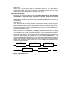
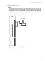
Figure 1: Typical Network Layout ........................................................................................ 1
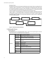
Figure 2: Single Network Break .......................................................................................... 3
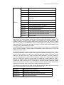
Figure 3: Panel Removed from Network ............................................................................. 4
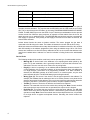
Figure 4: Four Wire Device Wiring (Typical) ....................................................................... 7
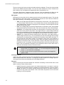
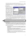
Figure 5: Modul-R System Window ..................................................................................... 9
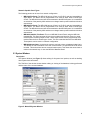
Figure 6: Switches Window ................................................................................................. 13
Figure 7: Groups Window ................................................................................................... 14
Figure 8: Panel Window ...................................................................................................... 16
Figure 11: Panel Outputs .................................................................................................... 19
Figure 12: Options Dialog ................................................................................................... 21
Figure 13: Default Key Assignments ................................................................................... 23
Figure 14: Dialer Settings .................................................................................................... 25
Figure 14: Dialer Configuration 1 ........................................................................................ 26
Figure 15: Dialer Configuration 2 ........................................................................................ 27
Figure 16: Call Directions .................................................................................................... 28
Figure 17: Zone Data .......................................................................................................... 29
Figure 18: Dialer Maintenance and Common Reporting Codes ......................................... 29
Figure 19: Circuits Window ................................................................................................. 30
Figure 20: Devices Window ................................................................................................ 30
Figure 22: Copy Window ..................................................................................................... 34
Figure 23: Internal Circuits Window .................................................................................... 35
Figure 24: Relate Window ................................................................................................... 36
Figure 25: Program Menu ................................................................................................... 39
Figure 26: Selector Screen ................................................................................................. 40
List of Tables
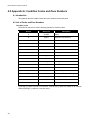
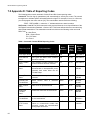
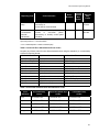
Table 1: Automatic Contact ID/SIA Reporting Codes ......................................................... 60
Table 2: Contact ID Zone Alarm/Restore Event Codes ...................................................... 61
Table 3: SIA Format Automatic Zone Alarm/Restore Codes .............................................. 61
iii