1
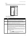
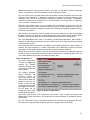
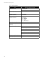
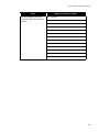
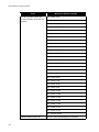
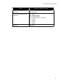
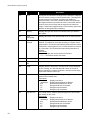
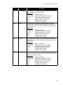
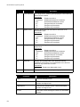
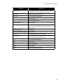
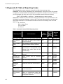
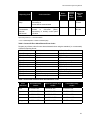
MR-2100/2200 Programming Manual
Zone
Hot Key Activation (Zone 90):
Function Number of the Hot key
pressed
Meaning of SubZone Number
019 - Switch 4 On
020 - Switch 5 On
021 - Switch 6 On
022 - Switch 7 On
023 - Switch 8 On
024 - Switch 9 On
025 - Switch 10 On
026 - Switch 11 On
027 - Switch 12 On
028 - Switch 13 On
029 - Switch 14 On
030 - Switch 15 On
031 - Switch 16 On
032 - Switch 1 Off
033 - Switch 2 Off
034 - Switch 3 Off
035 - Switch 4 Off
036 - Switch 5 Off
037 - Switch 6 Off
038 - Switch 7 Off
039 - Switch 8 Off
040 - Switch 9 Off
041 - Switch 10 Off
042 - Switch 11 Off
043 - Switch 12 Off
044 - Switch 13 Off
045 - Switch 14 Off
046 - Switch 15 Off
047 - Switch 16 Off
051 - Manual Restart
Network Reboot (Zone 92):
50
Unit ID of panel broadcasting the command