1
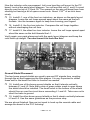
33. Solder the ground braid of the coax to the solder lug of the F-connector. Poor connections can lead to poor performance. Check your work and make sure the connection does not look like this: Poor F-Connector Installation (This connection style acts as a loop antenna and allows signals to radiate across the filter!) 34. Repeat steps 30 through 33 to attach the other F-connector. Your FMLP1 kit is now assembled and almost ready for use. Let’s install it in the case and call it a day! CUSTOM CASE ASSEMBLY The PVC enclosure will protect your electronics from many possible causes of damage giving you years worth of enjoyment and usage. The rugged design can be sealed with silicone RTV (after you verify its operation) to give you a weather tight seal ensuring top notch operation under almost any condition. 35. Remove the hex nuts from the F-connectors. 36. Insert one of the F-connectors into the hole drilled in the center of one of the PVC end caps. Insert it from the inside of the end cap. 37. Slide on an inner toothed washer and a hex nut then permanently tighten it in place. Slide the FMLP1 into the PVC body and twist PVC pieces together. 38. Attach the last F-connector to the other end cap as in step 36 and gently position the excess coax into the PVC body. Twist the entire assembly together and we’re ready to go! HOOK-UP AND APPLICATION GUIDELINES The FMLP1 is not polarized; the unit can be installed between the transmitter and antenna in either direction. It has been optimized for usage at 40 Watts or less in a 50 ohm environment. In low power applications such as 1 Watt, the 50 ohm match is not crucial. Applications on the higher end upward of 30 Watts will notice increased performance when L1, L2, and L3 are spread or compressed slightly for maximum power. FMLP1 • 17